Embed Size (px)
Citation preview

Copyright © ESB International Limited, all rights reserved.
Oweninny Wind Farm
June 2013
Oweninny Power Ltd.
Environmental Impact Statement
Chapter 19
Hydrology and Sediment

Oweninny Wind Farm
County Mayo
Environmental Impact Statement
June 2013
Table of Contents
19. HYDROLOGY AND SEDIMENT 19.1
19. 1 INTRODUCTION 19.1
19. 2 RECEIVING ENVIRONMENT 19.2 19.2.1 Site Characterization 19.2 19.2.2 Water Balance 19.3 19.2.3 Flooding 19.4 19.2.4 Cutaway Bog Rehabilitation 19.4 19.2.5 Sensitive Receptors 19.6
19. 3 POTENTIAL IMPACT OF THE DEVELOPMENT 19.6 19.3.1 Working in Cutaway Peatland 19.6 19.3.2 Windfarm Activities 19.7
19. 4 MITIGATION 19.7 19.4.1 Approach 19.7 19.4.2 Water Quantity 19.8 19.4.3 Sediment Control 19.9 19.4.4 Access Tracks 19.12 19.4.5 Turbines, Substations and Buildings Hardstanding 19.13 19.4.6 Borrow pit 19.14 19.4.7 Peat Repository 19.14 19.4.8 Batching plant 19.14 19.4.9 Tree Felling 19.15 19.4.10 Other Construction Settlement Control Measures 19.16
19. 5 MONITORING AND MAINTENANCE DURING CONSTRUCTION 19.16 19.5.1 Monitoring 19.16 19.5.2 Operational Phase 19.17 19.5.3 Decommissioning Phase 19.17
19. 6 CUMULATIVE IMPACTS 19.18
19. 7 CONCLUSIONS 19.18
List of Tables Table 19-1: Catchments and Turbines 19.3 Table 19-2. River Risk and Design Rainfall Return Periods 19.10
Hydrology and Sediment iii

Oweninny Wind Farm
County Mayo
Environmental Impact Statement
June 2013
Hydrology and Sediment iv
List of Plates Plate 19-1: Area Prior to Rewetting 19.5 Plate 19-2: The Same General Area as Plate 19-2, In 2010. 19.5 Plate 19-3: Typical Stone Check Dam in a Drainage Ditch 19.11
List of Figures Figure 19-1: Oweninny Site And Main River Catchments 19.21 Figure 19-2: Oweninny Site Hydrology 19.22 Figure 19-3: Water Level Recession Curve 19.23 Figure 19-4: River Sub-Catchments 19.24 Figure 19-5: Sample Of The Wind Farm Layout Showing Drainage Arrangement 19.25 Figure 19-6: Lough Dahybaun Catchment 19.26 Figure 19-7: Relationship Of Oweninny Wind Farm Site to Freshwater Pearl Mussel Records on the
Deel River 19.27 Figure 19-8: Borrow Pit And Drainage 19.28 Figure 19-9: Peat Deposition Area 19.29 Figure 19-10: Batching Plant And Substation 1 Drainage 19.30

Oweninny Wind Farm
County Mayo
Environmental Impact Statement
June 2013
19. HYDROLOGY AND SEDIMENT
19. 1 INTRODUCTION
Sediment loss and water management within the site are critical to protecting the water environment. Historically peat harvesting on the site gave rise to peat sediment loss from bare peat areas leading to downstream increases in suspended matter and sediment deposition. The rate of surface runoff at high flows was reduced by provision of additional storage within the drained areas of the peat bog. With the introduction of a sediment control system, comprising settlement lagoons and subsequent implementation of a bog rehabilitation plan by Bord na Mona, peat sediment loss has reduced significantly and water clarity is now good as reported by Inland Fisheries Ireland, see Chapter 10. It is important that activities associated with Oweninny wind farm do not result in any significant loss of sediment to the receiving rivers and that they complement the rehabilitation measures undertaken on the site, particularly during construction.
This section of the EIS considers the potential impacts relating to surface water hydrology and sediment loss from the construction areas.
The assessment is based primarily on:
Contoured Light Detection and Ranging (LiDAR) Mapping and OSi Aerial Photography1,
Bord na Mona Oweninny Bog Rehabilitation Plan2,
CIRIA, The SuDS Manual – C697, Planning for SuDS – C687, SUDS Best Practice Manual – C523, Site handbook for the construction of SUDS – C698, Control of water pollution from linear construction projects – C648 and Designing for exceedance in urban drainage – C6353,
EPA river maps and catchments (EPA ENVision environmental mapping system and EPA “Hydrotool”4,5
1 Osi Aerial Photography, Osi Mapviewer.
2 Bord na Móna, Oweninny Bog Rehabilitation Plan, 2003.
3 CIRIA: The SuDS Manual – C697, Planning for SuDS – C687, SUDS Best Practice Manual – C523, Site handbook for the construction of SUDS – C698, Control of water pollution from linear construction projects – C648, Designing for exceedance in urban drainage – C635, . CIRIA C532 – Control of Water Pollution from Construction Sites – C532 and Design of Flood Storage Reservoirs – B14.
4 EPA ENVision environmental mapping system, http://maps.epa.ie/InternetMapViewer/MapViewer.aspx.
5 EPA “Hydrotool”, http://watermaps.wfdireland.ie/HydroTool/Authentication/Login.aspx?ReturnUrl=%2fHydroTool%2fDef
Hydrology and Sediment 19.1
Oweninny Wind Farm
County Mayo
Environmental Impact Statement
June 2013
OPW and Mayo Co. Co. Flood hazard mapping and preliminary flood risk assessment6,7,8,.
19. 2 RECEIVING ENVIRONMENT
19.2.1 Site Characterization
The site is located on a catchment boundary between three catchments, the Oweninny/Owenmore (A), the northeastern Owenmore (B) and the Moy (C), see Figure 19-1. The Oweninny River drains the central part of the site. The Oweninny river is fed by the Srahmeen river and Knockmoyle Stream from the west and by numerous small tributary streams from the east (Fiddaungal, Fiddaunnaglogh, Fiddaunnameenabane, Fiddauncam and the Fiddaunnamuinggeery) before entering the Oweninny wind farm site. The Owenniny is joined by the Sheskin Steam which drains the forested south-eastern slopes of Slieve Fyagh and also forms the site’s internal boundary with the O’Boyles Bog area. The Oweninny and the Fiddaunnamuingeery form part of the site boundary. The Sruffaunnamuingabatia, which drains the Bellacorick Iron Flush SAC area within the site, flows westwards and joins the Oweninny river. The Oweninny is also joined by the Muing River which drains Lough Dahybaun within the site. The Owenmore drains a catchment of approximately 332 km2 before entering the sea at Tullaghan Bay. The Oweninny flows southwards, externally to the site and effectively dividing the site in two before joining the Owenmore turning westwards after Bellacorick Bridge and paralleling the N59. The Owenmore is joined at this location by the Altanabrocky river flowing northwards from the Nephin Mountains.
The north-eastern part of the site is drained by small tributaries (Fiddaunfura) which rise in Shanvodinnaun and flow eastwards to the main easterly flowing river, also named the Owenmore. This river rises in the townlands of Cluddaun and Shanetra to the north of the site before flowing eastwards becoming the Cloonaghmore River before entering the sea at Rathfran Bay which is within Killala Bay. It is also referred to as the Palmerstown River. The Cloonaghmore River drains a catchment of approximately 132 km2 before entering the sea at Rathfran Bay.
The south-eastern part of the site drains to tributaries of the Shanvolahan River (Fiddaunagosty, Shanvolahan and Fiddauntooghaun) before entering the Deel River which drains to Lough Conn and eventually joins the River Moy at Ballina before entering the sea at Killala Bay. The River Moy drains a catchment of approximately 1,966 km2 before entering the sea at Killala Bay. The area of the Shavolahan catchment before it enters the Deel River is approximately 23.7 km2.
ault.aspx
6 Mayo Co Co, Strategic Flood Risk Assessment for the Draft Mayo County Development Plan 2014 – 2020
7 OPW Flood Hazard Mapping, www.floodmaps.ie 8 OPW National Preliminary Flood Risk Assessment, www.cframs.ie
Hydrology and Sediment 19.2

Oweninny Wind Farm
County Mayo
Environmental Impact Statement
June 2013
Table 19-1 summarises the three main river catchments and the extent of proposed turbines and access tracks in each.
Table 19-1: Catchments and Turbines
Catchment Draining
to
Area
sq km No of Turbines
Owenmore (Oweninny) Tullaghan Bay 332 86
Cloonaghmore (Owenmore) Rathfran Bay 132 15
Deel (Shanvolahan) River Moy 1,966 11
The area is an Atlantic blanket peatland, comprising largely drained cutaway bog but with significant areas of rehabilitated cutaway and also remnant bog. The peat deposits generally vary in depth from 0.5m to 3.5m but 80% of the construction area has a depth less than one metre. Glacial till occurs in places and this generally underlies the peat. Small areas of glacial sand and gravel deposits are also present, particularly in the south and east of the site. Finally, alluvial deposits are shown to be present along the course of the Oweninny/Owenmore River.
There are natural rivers within the site as shown in Figure 19.2 and the area is drained by a network of manmade drainage ditches.
19.2.2 Water Balance
Long term rainfall and evaporation data was sourced from Met Éireann. The long-term (30-year) annual average rainfall (AAR) for the Oweninny/Owenmore Catchment of 187 sq km, to immediately downstream of the site, is 1,554mm.
The closest synoptic station where the average potential evapotranspiration (PE) is recorded is at Belmullet, Co. Mayo, located approximately 32km west of the site. The long term average annual PE for this station is 518mm/year. The effective annual average rainfall (ER) represents the water available for runoff or groundwater recharge and is the rainfall less the actual evapotranspiration. To determine Actual Evaporation (AE), a standard crop factor of 1.3 has been regularly applied to blanket bog settings in Ireland were the surface of the bog is dominated by sphagnum. However, at the Bellacorick site there is little or no sphagnum and a value of 1.3 would overestimate AE here. A conservative estimate of 1.1 is used for the Bellacorick site which equates to an AE of 570mm/year.The ER for the site is estimated at 984mm. During the months April to October, there is very little runoff or recharge. Most of the effective rainfall at field scale occurs in the Winter months.
There are no longterm recording surface water flow gauging stations in or near the site. In the 1950s and 1960s however, three water level gauging stations associated with the original Power Station recorded levels in the rivers for a short period and flows were measured at one of these, in the Owenmore River downstream of the site. These provide an indication of the surface water response at the time. Anecdotal observations at Oweninny during harvesting agree with field measurements of blanket peatland drainage made in a neighbouring bog at
Hydrology and Sediment 19.3

Oweninny Wind Farm
County Mayo
Environmental Impact Statement
June 2013
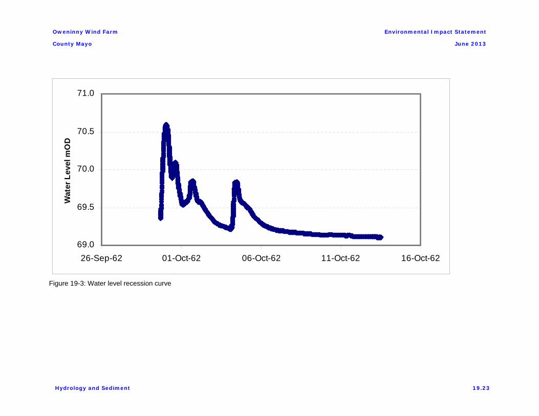
Glenamoy9, which concluded that flood runoff was reduced in frequency and amount, and summer flow of streams was increased. The bog rehabilitation programme would have reversed this process to some extent. A water level recession curve measured in 1962, prior to peat harvesting, is shown in Figure 19-3. for the channel downstream of the site. This plot indicates some storage in and around the peat and possibly in the underlying groundwater.
More recently, an investigation of groundwater at the Bellacorick Iron Flush SAC area within the site recorded water tables, phreatic pressures and flows where links between surface and groundwater were identified, see Chapter 18.
Flows estimated using the EPA Hydrometric System (Hydrotool), also suggest a relatively fast runoff, which is a characteristic of blanket peatlands. This estimation method does not account for the cutaway nature of the site, with rewetting and revegetation, explicitly. This rehabilitation has stabilised the sediment.
The objective is to minimise any potential impact on this water balance of the site.
19.2.3 Flooding
The Office of Public Works (OPW) compiles Flood Hazard Maps which record known historic flood locations for the entire country7. They are also in the process of preparing flood hazard maps based on a risk assessment. Flood Hazard Maps are tools used to assist with the management of development in floodplains and other areas at risk from tidal, fluvial or surface water flooding. OPW has prepared a national “Preliminary Flood Risk Assessment” Report8. Mayo County Council has prepared a flood risk assessment of its county development plan6 in line with requirements of the Regional Planning Guidelines 2010 to 2022.
Although there are no recorded incidences of flooding at or near the site, this would relate to local roads and houses. The area is a peatland where surface flooding is of course commonplace.
Flood Risk Assessment reports have been prepared of each substation, for the operation and maintenance building and for the visitor centre, see Appendix 15. They conclude that the developments comply with the principles of “The Planning System and Flood Risk Management - Guidelines for Planning Authorities, November 2009".
19.2.4 Cutaway Bog Rehabilitation
A Cutaway Bog Rehabilitation Plan has been implemented on the site. This involved detailed consultations with relevant agencies, authorities and affected parties to arrive at an implementation procedure to ensure minimum impact to the environment.
There are a significant number of features of the rehabilitation within the site that will benefit a Sustainable Drainage System (SuDS) approach to surface water management for the development.
These are:
9 Burke, W. 1967: Principles of drainage with special reference to peat. Irish Forestry 24,1–7.
Hydrology and Sediment 19.4
Oweninny Wind Farm
County Mayo
Environmental Impact Statement
June 2013
Vegetated Filter Strips
Existing Wetland
Existing Surface Ponds
Vegetated Drainage Channels
Existing Settlement Ponds.
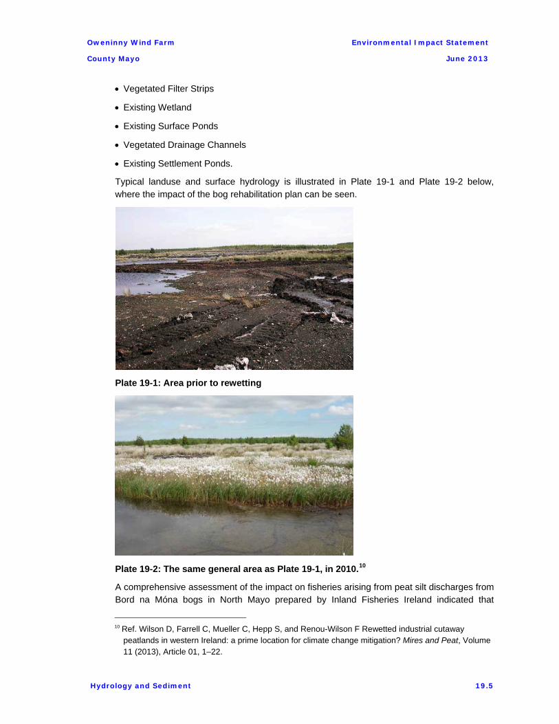
Typical landuse and surface hydrology is illustrated in Plate 19-1 and Plate 19-2 below, where the impact of the bog rehabilitation plan can be seen.
Plate 19-1: Area prior to rewetting
Plate 19-2: The same general area as Plate 19-1, in 2010.10
A comprehensive assessment of the impact on fisheries arising from peat silt discharges from Bord na Móna bogs in North Mayo prepared by Inland Fisheries Ireland indicated that
10 Ref. Wilson D, Farrell C, Mueller C, Hepp S, and Renou-Wilson F Rewetted industrial cutaway
peatlands in western Ireland: a prime location for climate change mitigation? Mires and Peat, Volume 11 (2013), Article 01, 1–22.
Hydrology and Sediment 19.5

Oweninny Wind Farm
County Mayo
Environmental Impact Statement
June 2013
significant peat loss to waters occurred from bare peat areas within the site in the past but these have reduced significantly due to the bog rehabilitation works undertaken by Bord na Móna since 2003. The current water status is considered acceptable.
19.2.5 Sensitive Receptors
Flow disruption or sediment loss to any of the receiving rivers would pose a significant risk. In addition to fisheries risk throughout the river system, five areas in particular are considered for special attention.
Shanvolahan-Deel River
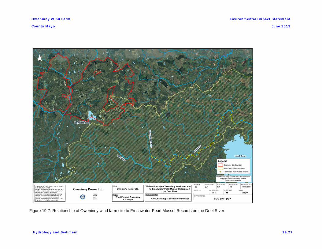
An area in the southeast of the site is particularly important as it drains to the Deel (Shanvolahan) River, which supports freshwater pearl mussel populations in downstream reaches.
Lough Dahybaun
The catchment area of Lough Dahybaun, located within the site, has been delineated from detailed LIDAR data, see Figure 19-6.
Geoheritage of Oweninny River
The only geoheritage feature within the environs of the site is the geomorphology of the banks of the Oweninny River itself, as it traverses through the central part of the site.
Iron Flush
The Surface Water – Groundwater interaction at the Iron Flush SAC within the site was investigated in 2012 and is reported in Chapter 18 of the EIS.
Bog Remnants
There are small areas of relatively undisturbed bog within the site.
19. 3 POTENTIAL IMPACT OF THE DEVELOPMENT
19.3.1 Working in Cutaway Peatland
Water and sediment management in and around the site has been the subject of international research over many years, from the 1960s9 to 201310. The experience gained in the area will be employed throughout the project, allowing a SUDS design which is site-specific and suited to the well-humified peat. Initially, water tables were lowered at the site by constructing shallow drainage ditches of 0.75m depth – there was no benefit at greater depths. The ditches needed to be at a very close interval of 4.5m as the well-humified peat is impermeable except in the pores near the surface. In the cutaway bog, peat banks remain vertical and the water table can be about 100mm below the surface.
Drainage work in a windfarm would normally pro-actively drain working areas and direct all flow and sediment within a designed drainage network. There is usually sufficient depth of outfall nearby all construction areas. However, in the undulating cutaway peat area of Oweninny, slopes are generally very low, some areas are flat and the likely outfall is a considerable distance from many construction areas. Although a drainage system was
Hydrology and Sediment 19.6

Oweninny Wind Farm
County Mayo
Environmental Impact Statement
June 2013
installed during peat extraction in most areas, this drainage system was largely revoked by the bog rehabilitation programme.
19.3.2 Windfarm Activities
Potential impacts that are typically associated with wind farm developments may include the following:
Unmanaged erosion and sediment deposition generated from ground disturbance could cause modification to stream channel morphology, potentially smothering habitats and impacting on aquatic flora and fauna, especially fish. Water abstracted for drinking can also be affected by sediment.
Any alteration of natural flows or subsurface hydrogeological patterns could disturb the water regime, particularly floods and droughts, unless properly managed.
The development of new access tracks across existing rivers has the potential to obstruct water flow.
Poorly designed drainage on unstable areas may increase the risk of landslide.
The potential impacts apply primarily during construction if the flow paths are interrupted or redirected. General disturbance of the vegetation cover during construction has the potential for short-term generation of high suspended sediment loads in rivers draining the area. This potential for an increased sediment loading will be short-term and will reduce as vegetation in disturbed areas re-establishes. Potential impacts may also arise in respect of increased sediment loading resulting from any dewatering of excavated areas.
The potential impacts can be mitigated by careful drainage design.
The historic planting of commercial coniferous forests in parts of the site at Oweninny has modified the hydrology of these planted areas of the site. Further potential alteration could arise from clearfelling in these areas. While the permanent removal of mature forests from large areas of the site could result in increased runoff directly into local rivers, the felling plan to facilitate the wind farm project proposal are not considered significant in relation to what is envisaged in the overall forest management plan.
As part of the wind farm development, a number of existing river crossings (e.g. across the Muing and Sruffaunnamuinggabatia rivers) and culverted crossings across smaller streams will require upgrading. Potential impacts could result from disturbance of the river bed and flow constriction.
Foul effluent from kitchens and washrooms will be treated and discharged to ground through appropriately designed proprietary treatment and percolation areas. Rainwater harvesting will be provided at offices and excess surface runoff from roofs will be lead to soakaways.
19. 4 MITIGATION
19.4.1 Approach
The approach to surface water management for Oweninny Wind Farm Project integrates with
Hydrology and Sediment 19.7
Oweninny Wind Farm
County Mayo
Environmental Impact Statement
June 2013
the methods already agreed with the environmental authorities for bog rehabilitation at Oweninny. These methods are tailored to the characteristics of the site and to the specific properties of the peat, and they form part of a suite of techniques used in the Oweninny Bog Rehabilitation Plan and in Sustainable Drainage Systems (SuDS).
The bog rehabilitation programme at Oweninny is based on three measures aimed at encouraging re-vegetation of the site and stabilising it to minimise suspended solids loading to receiving rivers: undisturbed buffer areas alongside rivers; rewetting of areas by blocking drains; and ploughing of a small number of areas with little or no peat to promote revegetation.
The objective of the wind farm hydrology and sediment control design is to replicate these natural drainage patterns within the project. The following design philosophy has therefore been adopted:
Limit the impermeable fraction of the development, with particular attention to sensitive locations.
Re-direct upslope clean surface water around structures and providing first stage treatment to construction/operation water locally at structures to remove and isolate contamination at source.
Thereafter, spread surface runoff across the surface to maximise the benefits of the existing site characteristics through use of buffer zones and rehabilitation areas.
Surface water generated on the development area will predominantly continue to drain as it would under pre-development conditions. Access tracks and structures are generally located on relatively high areas and on local watershed boundaries, away from rivers. The system is a diffuse system. First-stage local treatment is provided throughout the site in settlement ponds and lagoons, with the type of pond and lagoon designed on the basis of the bog rehabilitation and SuDS features available and on the risk to the nearest river. In very sensitive areas, the number of turbines is minimised and additional settlement SuDS measures are proposed.
19.4.2 Water Quantity
The development has been minimised to the extent possible:
The footprint of the development (areas of tracks, cranepads, borrow pits, substations, visitor interpretive centre and batching plant) will occupy approximately 0.45% of the upper Oweninny/Owenmore catchment after it passes through the site.
The footprint of the development will occupy approximately 0.67% of the upper Cloonaghmore/Owenmore catchment after it passes through the site.
The footprint of the development will occupy and approximately 0.35% of the upper Deel/Shanvolahan catchment after it passes through the site.
These figures reduce significantly as the catchment extends further downstream.
The localised footprint areas associated with the tributaries’ sub catchment areas, see Figure 19-4, vary from 0.0% to 3.9%, and the highest percentage occurs in the Muing river
Hydrology and Sediment 19.8

Oweninny Wind Farm
County Mayo
Environmental Impact Statement
June 2013
catchment with all others ranging from 0.0% to 1.9%. Excluding the stone access tracks, which are not impervious, the percentages range from 0.0% to 3.1%.
Although runoff from constructed areas will form a relatively high percentage runoff, this can be compared to the high percentage runoff of the existing peat bog, as compared say to mineral soils. Hence there is no significant increase in runoff and local first-stage treatment at each structure will deal with the same local runoff as occurs at present. At isolated areas of bare earth, where peat was completely removed, the link between surface runoff and groundwater is highly disturbed, leading to springs and local surface pathways. Again, the local water balance will be preserved by local first-stage treatment and second-stage treatment on the bog surface.
This approach does not require special measures to deal with extreme rainfall events. It facilitates access to and operation of the electrical substations, wind turbines metorological masts and other buildings within the development during very extreme events.
Hence the potential impact for the footprint area is related to sediment rather than flow.
19.4.3 Sediment Control
Sediment control structures and associated local drainage will be constructed prior to the main construction at each site. An Erosion and Sediment Control Plan has been prepared for the site and will be fully implemented, see Appendix 16.
Sediment loss from the site is particularly important to all rivers draining the site given their important salmonid nature. It is also particularly important in the area that drains to the Deel River, which supports freshwater pearl mussel populations in downstream reaches, some 8km distance. This receiving water has very high sensitivity to sediment loss from the site. Sediment loss to the receiving rivers would also pose a significant risk to salmonid spawning areas and juvenile fish. The control of flow and sediment within the existing regime will ensure that the present buffer to runoff and sediment loss within the site is preserved.
The only geoheritage feature within the environs of the site is the geomorphology of the banks of the Oweninny River. No works are proposed on the river banks, with the exception of the replacement or upgrading of the existing river crossing within the site. It is not anticipated that this upgrade will affect the river bank substantially beyond the extent of the existing crossing and is unlikely to present a significant risk.
The layout design for the development has minimised the area to be disturbed by construction through rationalising the access track network serving turbine locations and locating turbine hardstandings and access tracks in areas of shallow peat depths. Proposals to manage the potential for erosion of sediment and the control of activated sediment are set out herein and will be incorporated into the Construction Environmental Management Plan which will be a requirement for site construction.
Settlement Lagoons and Ponds
Settlement ponds and/or lagoons are the main features proposed for first-stage treatment at each structure, followed by second-stage SuDS measures between the structure and the nearest river. The second stage will also control sediment and they include spreading flow across the peat surface and/or into large artificial ponds and wetlands.
Hydrology and Sediment 19.9

Oweninny Wind Farm
County Mayo
Environmental Impact Statement
June 2013
First-stage treatment has been designed to provide initial detention for the settlement of solids activated during local earthworks, based on their contributing area and rainfall for the particular risk assessed for the specific structure location. A peat particle settlement velocity of 0.0025m/s11 and a standard pond width of 8m were chosen, allowing ease of maintenance. Rainfall return periods of 10, 30 and 100 years have been applied to different areas of the site in accordance with identified risk to rivers, that is, depending on:
the number and quality of subsequent measures of surface water treatment available following discharge from the pond, and on
the proximity of the pond to a local river.
The required pond length was calculated from this. The rainfall for these return periods were obtained from Met Eireann12, and runoff flow rates for these return periods were derived using the Rational Formula with a runoff coefficient (Cv) of 0.70 which is consistent with the upper limit of the range recommended for stripped ground. A ten-minute design duration is appropriate for all structures, apart from the large peat repository where thirty minute duration was applied to a pond that will serve half of the site. A conservative instantaneous time of entry is assumed.
Ponds comply with CIRIA Guidance C648. Six types of ponds have been designed and, depending on their location within the site, they have been sized for different return periods, in accordance with Table 19-2.
Table 19-2. River Risk and Design Rainfall Return Periods
Location relative to River and Number of Subsequent Treatment Measures
Rainfall Return Period years
Peak Rainfall intensity mm/10min
River in close proximity and 1 subsequent SuDS treatment measure
100 23.2
River nearby and 1 to 2 subsequent SuDS treatment measures
30 16.7
Large distance to nearest river and 2 or more subsequent SuDS treatment measures
10 12.3
About 50% of eroded peat particles are finer than 0.2mm in diameter with 10% finer than 0.035mmError! Bookmark not defined..
The pond hydraulic and sediment design criteria are:
Standard dimensions of base width 5m, top width 8m, depth 2m (water depth 1.5m) and side slopes 1:0.75 were chosen to suit a standard 12 tonne excavator with a 1.5m jib extension. Lengths are then varied to suit risk and load. This excavator can clean the pond from both sides with minimum disturbance.
11 Mulqueen, J, Rodgers, M, Marren N and Healy, M.G. Erodibility of Hill Peat. Irish Journal of
Agricultural and Food Research 45: 103–114, 2006 12 Met Eireann, 2007. Estimation of Extreme Rainfall Depths.
Hydrology and Sediment 19.10

Oweninny Wind Farm
County Mayo
Environmental Impact Statement
June 2013
Discharge will be via a 450mm diameter twin-wall pipe with a flap valve installed, to provide isolation during cleaning.
In the five very sensitive areas near the Shanvolahan River, Lough Dahybaun, Oweninny channel, Iron Flush and Bog Remnants, a piped inlet with a manually operated flap valve will be installed on the settlement pond. This valve can be closed preventing incoming flow in the event of an environmental incident, thus protecting the pond.
At structures that are a long way from rivers and with extensive subsequent surface treatment, the first-stage treatment settlement pond may be replaced altogether by an artificial SUDS lagoon. Such a lagoon would be larger than a designed settlement pond, it would be fitted to the local topography allowing for continuous wetting to suit the bog rehabilitation plan. It will allow inlet and outlet flows across a wider area.
Swales
A swale is an open gently sloping grassed drainage channel. A swale may be used to collect and convey drainage water to the lagoons and special ponds, trapping sediment and enhancing filtration.
Check Dams
Check dams are small temporary barriers that will be constructed across larger areas of concentrated flow at structures. Their purpose is to reduce the velocity and to slow the rate of runoff. In steeper parts of site, check dams will be placed in the drainage channels, effectively creating ponding which will assist in sediment removal, see Plate 19-3.
Plate 19-3: Typical stone check dam in a drainage ditch
Hydrology and Sediment 19.11

Oweninny Wind Farm
County Mayo
Environmental Impact Statement
June 2013
19.4.4 Access Tracks
The process of rewetting through drain blocking on the site has detained surface water on site thereby creating wetted areas and the conditions required for native peatland vegetation to establish. This is also very effective at trapping peat silt particles. Early stage rehabilitation areas are characterised by many small deep ponds, many larger shallow ponds and exposed peat surface areas. Access track drainage will be directed onto the peat surface and to these pond areas where feasible, providing for treatment and attenuation of surface water generated on access tracks. Some mature wetland areas offer substantial benefits to surface water drainage. Significant detention and attenuation of runoff can be achieved.
Drainage from the locations of turbines and associated development areas has been carefully selected to avoid the ecologically significant bog remnant areas. Consequently the surface water drainage proposals associated with these areas will have no hydrological impact on these ecologically important areas of the site.
Access tracks will be above the existing ground level where peat is shallow, that is, across 80% of the site. They will have a camber in both directions. Where peat excavated for the access track construction is sidecast there will be gaps left in this side cast peat to allow surface water flow paths through to the surrounding area. Where possible, the access tracks have been strategically positioned on watersheds so as to allow runoff in both directions. However, in the limited areas where the natural overland flow paths are interrupted by the line of the access track, regular culverts/ drainage paths will be provided so that the access tracks do not interfere with the natural hydrology of the site. These drainage paths will have check dams at regular intervals on any access trackside drains where the longitudinal access track gradient exceeds 10%. This will further promote treatment and detention of surface water runoff from the access track.
Surface cross drains will be installed on tracks that are particularly steep and have long gradients.
Access tracks will be below existing ground level, where peat depths in excess of one metre cannot be avoided, that is, across 20% of the site to the east. Temporary local drainage will be installed to allow construction of the track sub-base. The final track will camber to both sides and be provided with a v-notch drain at both sides. This drain will follow the longitudinal fall in the track until the access track level is again above the surrounding ground level. At this point, ‘finger drains’ perpendicular to the access track will discharge runoff from the access track over surrounding lower lying ground. Should a low point of the access track and consequently the drains coincide with the access track level below existing ground, the access trackside drain will diverge from the access track in the direction of nearest lower ground.
Check dams will be provided at regular intervals on any access trackside drains where the longitudinal access track gradient exceeds 10%. This will further promote treatment and detention of surface water runoff from the access track.
Hydrology and Sediment 19.12

Oweninny Wind Farm
County Mayo
Environmental Impact Statement
June 2013
19.4.5 Turbines, Substations and Buildings Hardstanding
An open drainage ditch will be located on the down slope side(s) of each of the turbine hardstanding development areas. Where possible this drainage ditch will be profiled as a swale with side slopes of 1:3. This drainage ditch/ swale will be easily maintainable from the edges of the hardstanding and will discharge to first-stage treatment in a dedicated settlement pond/lagoon, an example is shown in Figure 19-5. The type of settlement pond/lagoon at each location has been selected on the basis of the sensitivity of the area. Finally, discharge from the first-stage treatment system will be overland for further treatment on the surface.
Peat excavated for the construction of the hardstanding will be placed in an adjoining area of the hardstanding so that runoff from this area will also be routed through the specific water first-stage treatment measures at the hardstanding.
The particular sensitive areas are considered next.
Lough Dahybaun
The design of the wind farm layout has examined the catchment and there is a suitable location for a turbine and crane hardstand, with 1.2 km of access track. The access track will be constructed along the existing railway line which minimises sediment disturbance, see Figure 19-6.
Additionally this access track forms a physical barrier separating the wind turbine construction area from the lake. The construction area is located approximately 950m from the lake and no direct discharge from the construction site to drainage flowing to the lake will occur. The construction site drainage will be directed to a settlement pond/lagoon and subsequently to overland flow as indicated previously.
In addition a large artificial lagoon, previously installed by Bord na Móna as part of the Oweninny peat harvesting operations, is located between the access track and Lough Dahybaun and will provide additional settlement for solids. All existing land drains in this area will be audited and check dams installed as required.
Fiddaunatooghaun Stream (Shanvolahan/Deel Catchment)
Seven wind turbine construction sites and access trackways are located within the upper watershed area of the Fiddaunatooghaun stream catchment. An existing railway embankment, which was part of the Bord na Móna peat harvesting operations, forms a physical barrier between six of the turbines and the small first and second order streams in the upper catchment. One turbine site, T110, is within 100m of a small stream feeding into the Fiddaunatooghaun. This is located on bare earth by design where all peat has been removed. The drainage from this turbine passes through a settlement pond / lagoon and subsequently to an existing Bord na Móna silt pond within the stream before entering the Fiddaunatooghaun. The construction site is approximately 8km from the nearest freshwater pearl mussel recorded population which is located at the confluence of the Deel and Shanvolahan rivers see Figure 19-7.
Hydrology and Sediment 19.13

Oweninny Wind Farm
County Mayo
Environmental Impact Statement
June 2013
Geoheritage of Oweninny River
No works are proposed on the river banks, with the exception of the replacement or upgrading of the existing river crossing within the site. It is not anticipated that this upgrade will affect the river bank substantially beyond the extent of the existing crossing and is unlikely to present a significant risk.
Bellacorick Iron Flush
The layout surrounding the Iron Flush is discussed in Chapter 18 where construction is considered in detail. There will be no significant impact.
Bog Remnants
Particular attention was given to keeping turbines away from significant bog remnants, to the extent possible and away from replacement siltation areas and riparian zones. Nearly all bog remnants have been avoided except in a small number of cases where minor incursions occur due to the necessity of the wind resource design and where existing Bord na Móna roads and paths were already established.
19.4.6 Borrow pit
Investigation of the site has indicated that materials suitable to support construction are available on site. These materials will be won through the excavation of a shallow borrow pit which may be inundated by groundwater. It is intended that the working of the pit will take place through the water table in a water filled excavation, i.e. no pumping of groundwater will take place to facilitate excavation. Excavated material will be dredged and left to dry on the storage area adjacent to the site before being loaded onto trucks, see Figure 19-8. The gravel storage area will be drained to a settlement pond/lagoon and then to overland flow for approximately 450m to a small tributary of the Sruffaunnamuingabatia river.
19.4.7 Peat Repository
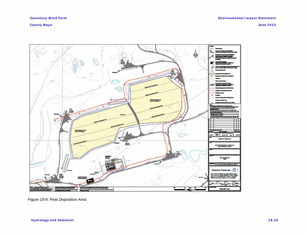
In Phase 3 of the project, peat will be excavated from areas, such as deep peat areas, that are not suitable for sidecasting of peat. This may arise due to the depth of peat in certain locations or due to proximity to sensitive receptors. The peat that is not sidecast will be placed in a peat repository that will be constructed on an area of cutaway bog with a designed local runoff and sediment control structure followed by diffuse dispersion on the surrounding peat surface.
The peat deposition area is enclosed on three sides by the existing Bellacorick wind farm access tracks. A new access track on the remaining westerly side, between T70 and T83, will be constructed as part of the Oweninny development which will form a boundary some 150m from the Muingamolt River. Internal access tracks within the repository area will be constructed to facilitate peat deposition. The peat respository area will be drained through the access tracks to a settlement pond system with subsequent overland flow to a large existing Bord na Móna artificial pond, see Figure 19-9.
19.4.8 Batching plant
The concrete batching plant location will be drained northwestwards through a settlement pond/lagoon and then through overland flow to a flat area comprising cutover bog with some
Hydrology and Sediment 19.14

Oweninny Wind Farm
County Mayo
Environmental Impact Statement
June 2013
exposed gravels and an extensive area of cutover bog with high cover of rushes, see Figure 19-10. The settlement pond/lagoon is located approximately 900m from a tributary of the Oweninny River flowing through the central section of the site. A water body formerly known as Lough Nagappal is located about 117m south of the batching plant site but the topography is such that natural gradients will not allow any discharge to the lake. The direction of overland flow from the batching plant is westerly and not southerly and no impact on this water body will occur.
19.4.9 Tree Felling
The impact of commercial timber harvesting on stream flow regimes has been studied in the past. Robinson et al presents a study of flow changes in four nested catchments in mid-Wales with increase of total annual flows13. Similar flow increases up to 30% were observed on 100% clearfell sites14. The results indicated that partial felling produced little increase in peak flows. In a similar study in the Burrishule catchment in County Mayo15, slight peak flow increase was observed in two sub-catchments after harvesting. However, statistical analysis indicated that the increase was not significant. The study further confirmed that the impact of harvesting on the peak flow was small. Similar studies across Europe16, found that the impact of forest harvesting on extreme flows was relatively small and difficult to detect in the North West European conifers.
In some areas of felling, it may be possible to block existing forestry drainage networks at intervals in order to slow the rate of runoff to the drains. The forest plantation areas at Oweninny will not be felled until post 2020, as stated in the Forest Management Plan for the area. The requirement for clearfelling to facilitate construction along access tracks and as keyhole felling at turbine and crane stand locations will not arise until Phase 3 of the project. This is likely to coincide with the main felling plan. If it does not, approximately 1.4% of the present forest plantation will be clearfelled to accommodate the development; otherwise the area will be felled as part of the felling plan.
The forest plantation in these areas was planted in the late 1980’s and early 1990’s and is drained directly to the rivers with no intervening buffer zone as occurs with more recent forest plantation areas. Modern forest practice undertaken in accordance with the Forest Service Guidelines will be implemented. In practice this will result in the restructuring of the drainage to prevent direct flow to the river systems through development of riparian buffer zones. Runoff should also decline naturally as re-vegetation of the felled areas and buffer zones
13 Robinson, M. and Dupeyrat, A. (2005). Effects of commercial forest felling on streamflow regimes at Plynlimon.
Hydrological Processes 19:1213-1226. 14
Johnson R. 1998. The forest cycle and low river flows: a review of UK and international studies. Forest Ecol.
Manag. 109: 1-7
15 Xiao, L, Robinson, M, Rodgers, M, O’Connor, M, O’Driscoll, C, Asam, Z. UNESCO IHP Irish National Hydrology
Conference 2011. Impact Of Blanket Peat Forest Harvesting On Stream Flow Regime – A Case Study In The Burrishoole Catchment, Co Mayo.
16 Robinson M., et al. 2003. Studies of the impact of forests on peak flows and baseflows: a European perspective.
Forest Ecol. Manag. 186: 85-97.
Hydrology and Sediment 19.15

Oweninny Wind Farm
County Mayo
Environmental Impact Statement
June 2013
occurs.
While the permanent removal of mature forests from large areas of the site could result in increased runoff directly into local rivers, the known and possible changes to the current felling plan to facilitate the wind farm project proposal are not considered significant in relation to what is envisaged in the overall forest management plan.
19.4.10 Other Construction Settlement Control Measures
Additional temporary lagoons and if necessary settlement ponds will be constructed around the site should the need for these be identified. Portable propriety settlement systems will be used in conjunction with at risk activities in particular locations as required.
Temporary wheel wash facilities will be provided and utilised for heavy goods vehicles leaving the site. Runoff from this area will enter a dedicated lagoon.
In areas of significant crossfall, clean water runoff drains up to 0.5m deep will direct flow to peat surface areas away from the works. This will provide a significant reduction of the volumes of potentially discoloured run-off that would otherwise require treatment.
19. 5 MONITORING AND MAINTENANCE DURING CONSTRUCTION
19.5.1 Monitoring
There will be no new point discharges to rivers from the developmentsite.
Monitoring points will be set up at the outlet of those sediment control points located closest to rivers. The predominant test will be for suspended solids. Turbidity will also be tested for and recorded. Other tests can be added should there be any indication of other types of pollutants arising from construction activities on the site.
Peat extractions in sensitive locations will be secured in advance of predicted rainfall. In the unlikely event of works being unavoidably close to rivers, vehicular and equipment access will be restricted to working surfaces / pads as appropriate and bogmats or other surface protection used as required.
Procedures for maintenance of windfarm hydrology will include the following measures:
A programme of regular cleaning, maintenance and inspection of the site runoff treatment system will be adopted to ensure it functions correctly. Sediment protection measures will be regularly inspected, and any collected sediment will be cleared out in dry weather to ensure maximum capacity can be maintained.
Lagoons will be checked for leakage, particularly following periods of heavy rainfall. Travel paths of surface water run-off to downstream receptors will be examined.
Growing vegetation will be left in place at ditches as this will aid in the filtering of some of the sediments.
The key lagoons and designed settlement ponds will be assessed and restored at the end of construction.
Hydrology and Sediment 19.16

Oweninny Wind Farm
County Mayo
Environmental Impact Statement
June 2013
A drainage management protocol will be incorporated into the management procedures for the operation of the wind farm.
The development will form part of a Windfarm Environmental Management System certified to ISO14001. This includes a draft Construction Environmental Management Plan (CEMP), incorporating the Erosion and Sediment Control Plan which describes water management measures to control water runoff and drain hardstandings and other structures during the construction phase. It integrates local water management with the existing bog restoration plan and it is designed to minimise the potential for effects on surface water, groundwater, soils and subsurface water quality. Also included is an Incident Plan to be followed should a pollution event occur. This draft plan will be updated following receipt of planning approval with the planning conditions, if any, that relate to environmental management of flows and sediment. Appropriate construction and operation personnel working on the site will be trained in its use.
19.5.2 Operational Phase
As the windfarm will be developed in phases, parts of the site will remain under construction as phase 1 and phase 2 become operational. For the operational phases of the wind farm:
The programme of regular cleaning, maintenance and inspection of the site runoff treatment system will continue to be adopted to ensure it functions correctly. This will include inspection of the sediment protection measures, and removal and disposal of any collected sediment as described for the construction phase
Lagoons will continue to be checked for leakage, particularly following periods of heavy rainfall and routes to surface waters reviewed.
The revegetation of bare earth areas associated with ditches and swales will be monitored to determine if additional action is required.
The key lagoons and designed settlement ponds will continue to be assessed.
A drainage management protocol will be incorporated into the management procedures for the operation of the wind farm.
19.5.3 Decommissioning Phase
The decommissioning will be undertaken in accordance with a detailed decommissioning plan for the site agreed with the planning authority. The existing Bellacorick windfarm will be decommissioned before construction of the final part of phase 3 of the proposed development.
Decommissioning of the Oweninny wind farm will give rise to some limited ground disturbance and no requirement for any additional drainage. The wind farm is expected to be operational for a minimum period of twenty five years during which time the impact of the bog rehabilitation programme will be almost fully realised with large areas of bare peat revegetated. It is expected that any drainage channel and settlement ponds created as part of the sediment control measures will also have become revegetated. Decommissioning will involve covering over with peat material all foundations, crane hardstands and access tracks unless any of this infrastructure is required on site. As this has the potential to generate
Hydrology and Sediment 19.17

Oweninny Wind Farm
County Mayo
Environmental Impact Statement
June 2013
sediment through surface flow, an assessment of the effectiveness of the existing drainage system to control sediment in runoff will be made at that time and if warranted, an updated drainage control system will be designed and agreed with the planning authority.
Decommissioning can also take place over an extended time period, minimising the extent of areas at any one time which could generate sediment-laden runoff.
Impacts during the decommissioning period are expected to be insignificant.
19. 6 CUMULATIVE IMPACTS
The nature of the diffuse drainage system, designed and integrated with the bog rehabilitation programme, will mitigate the potential for accumulation of surface runoff and sediment in the site.
19. 7 CONCLUSIONS
The hydrology and sediment control system on the windfarm development is designed to be sustainable using SuDS techniques and integrating with the bog rehabilitation plan. Drainage from the structures is compatible with rewetting of the bog.
The percentage runoff in the river catchments draining the site will not be significantly changed.
Clearfelling of mature forest can result in a local higher water table, which is aligned with the rewetting programme of bog rehabilitation.
The potential increase in sediment, particularly during construction, has been factored into the design of the SuDS system, based primarily on designed first-stage treatment at structures using local settlement lagoons and ponds, followed by spreading flow across the peat surface, wetlands and existing ponds.
It is worth noting that the drainage regime at the site is already a modified one, with its natural hydrology having been amended by peat extraction and by commercial forests.
Hydrology and Sediment 19.18

Oweninny Wind Farm
County Mayo
Environmental Impact Statement
June 2013
LIST OF REFERENCES
Ref. 1 Osi Aerial Photography, Osi Mapviewer.
Ref. 2 Bord na Mona, Oweninny Bog Rehabilitation Plan, 2003.
Ref. 3 CIRIA: The SuDS Manual – C697, Planning for SuDS – C687, SUDS Best Practice Manual – C523, Site handbook for the construction of SUDS – C698, Control of water pollution from linear construction projects – C648, Designing for exceedance in urban drainage – C635, . CIRIA C532 – Control of Water Pollution from Construction Sites – C532 and Design of Flood Storage Reservoirs – B14.
Ref. 4 EPA ENVision environmental mapping system, http://maps.epa.ie/InternetMapViewer/MapViewer.aspx.
Ref. 5 EPA “Hydrotool”, http://watermaps.wfdireland.ie/HydroTool/Authentication/Login.aspx?ReturnUrl=%2fHydroTool%2fDefault.aspx
Ref. 6 OPW Flood Hazard Mapping, www.floodmaps.ie
Ref. 7 OPW National Preliminary Flood Risk Assessment, www.cframs.ie
Ref. 8 Mayo Co Co, Strategic Flood Risk Assessment for the Draft Mayo County Development Plan 2014 – 2020
Ref.11 Met Eireann, 2007. Estimation of Extreme Rainfall Depths.
Ref. 9 Hydroenvironmental Services, Oweninny Windfarm, Report on Investigation of Iron Flush SAC, 2012.
Ref. 10 Burke, W. 1967: Principles of drainage with special reference to peat. Irish Forestry 24,1–7.
–––– 1975a: Aspects of the hydrology of blanket peat in Ireland. Hydrology of marsh-ridden areas. Proceedings of the Minsk symposium, June 1972. IAHS Studies and Reports in Hydrology, 19. Paris: Unesco Press, 171–82.
–––– 1975b: Effect of drainage on the hydrology of blanket-bog. Irish Journal of Agricultural Research 14, 145–62.
Ref. 11 Mulqueen, J, Rodgers, M, Marren N and Healy, M.G. Erodibility of Hill Peat. Irish Journal of Agricultural and Food Research 45: 103–114, 2006
Robinson, M. and Dupeyrat, A. (2005). Effects of commercial forest felling on streamflow regimes at Plynlimon. Hydrological Processes 19:1213-1226.
Ref. 12 Johnson R. 1998. The forest cycle and low river flows: a review of UK and international studies. Forest Ecol. Manag. 109: 1-7.
Ref. 13 Xiao, L, Robinson, M, Rodgers, M, O’Connor, M, O’Driscoll, C, Asam, Z. UNESCO IHP Irish National Hydrology Conference 2011. Impact Of Blanket Peat Forest Harvesting On Stream Flow Regime – A Case Study In The Burrishoole Catchment, Co Mayo.
Hydrology and Sediment 19.19

Oweninny Wind Farm
County Mayo
Environmental Impact Statement
June 2013
Hydrology and Sediment 19.20
Ref. 14 Robinson M., et al. 2003. Studies of the impact of forests on peak flows and baseflows: a European perspective. Forest Ecol. Manag. 186: 85-97.

Oweninny Wind Farm
County Mayo
Environmental Impact Statement
June 2013
Figure 19-1: Oweninny site and main river catchments
Hydrology and Sediment 19.21

Oweninny Wind Farm
County Mayo
Environmental Impact Statement
June 2013
Figure 19-2: Oweninny site hydrology
Hydrology and Sediment 19.22
Oweninny Wind Farm
County Mayo
Environmental Impact Statement
June 2013
69.0
69.5
70.0
70.5
71.0
26-Sep-62 01-Oct-62 06-Oct-62 11-Oct-62 16-Oct-62
Wat
er L
evel
mO
D
Figure 19-3: Water level recession curve
Hydrology and Sediment 19.23

Oweninny Wind Farm
County Mayo
Environmental Impact Statement
June 2013
Figure 19-4: River sub-catchments
Hydrology and Sediment 19.24

Oweninny Wind Farm
County Mayo
Environmental Impact Statement
June 2013
Figure 19-5: Sample of the wind farm layout showing drainage arrangement
Hydrology and Sediment 19.25

Oweninny Wind Farm
County Mayo
Environmental Impact Statement
June 2013
Figure 19-6: Lough Dahybaun Catchment
Hydrology and Sediment 19.26
Oweninny Wind Farm
County Mayo
Environmental Impact Statement
June 2013
Figure 19-7: Relationship of Oweninny wind farm site to Freshwater Pearl Mussel Records on the Deel River
Hydrology and Sediment 19.27

Oweninny Wind Farm
County Mayo
Environmental Impact Statement
June 2013
Figure 19-8: Borrow pit and drainage
Hydrology and Sediment 19.28
Oweninny Wind Farm
County Mayo
Environmental Impact Statement
June 2013
Figure 19-9: Peat Deposition Area
Hydrology and Sediment 19.29

Oweninny Wind Farm
County Mayo
Environmental Impact Statement
June 2013
Figure 19-10: Batching Plant and Substation 1 drainage
Hydrology and Sediment 19.30

Oweninny Wind Farm
County Mayo
Environmental Impact Statement
June 2013
Hydrology and Sediment 19.31

Oweninny Wind Farm
County Mayo
Environmental Impact Statement
May 2013
Hydrology and Sediment 32


![Fluxes of water and solute in a coastal wetland …...Journal of Hydrology ELSEVIER [1] Journal of Hydrology 164(1995) 89-107 Fluxes of water and solute in a coastal wetland sediment](https://img.dokumen.tips/doc/110x75/5fab0ddcbf9557730c3401da/fluxes-of-water-and-solute-in-a-coastal-wetland-journal-of-hydrology-elsevier.jpg)