Embed Size (px)
Citation preview
CHAPTER 16. LABORATORIES
MODERN laboratories require regulated temperature, humid- ity, relative static pressure, air motion, air cleanliness, sound, and exhaust. This chapter addresses biological, chemical, animal, and physical laboratories. Within these generic categories, some laboratories have unique requirements. This chapter provides an overview of the HVAC characteristics and design criteria for laboratories, including a brief overview of architectural and utility concerns. This chapter does not cover pilot plants, which are essentially small manufacturing units.
The function of a laboratory is important in determining the appropriate HVAC system selection and design. Air-handling, hydronic, control, life safety, and heating and cooling systems must function as a unit and not as independent systems. HVAC systems must conform to applicable safety and environmental regulations.
Providing a safe environment for all personnel is a primary objective in the design of HVAC systems for laboratories. A vast amount of information is available, and HVAC engineers must study the subject thoroughly to understand all the factors that relate to proper and optimum design. This chapter serves only as an introduction to the topic of laboratory HVAC design. HVAC systems must integrate with architectural planning and design, electrical systems, structural systems, other utility systems, and the functional requirements of the laboratory. The
HVAC engineer, then, is a member of a team that includes other facility designers, users, industrial hygienists, safety officers, operators, and maintenance staff. Decisions or recommendations by the HVAC engineer may significantly affect construction, operation, and maintenance costs.
Laboratories frequently use 100% outdoor air, which broadens the range of conditions to which the systems must respond. They seldom operate at maximum design conditions, so the HVAC engineer must pay particular attention to partial load operations that are continually changing due to variations in internal space loads, exhaust requirements, external conditions, and day-night variances. Most laboratories will be modified at some time. Consequently, the HVAC engineer must consider to what extent laboratory systems should be adaptable for other needs. Both economics and integration of the systems with the rest of the facility must be considered.
LABORATORY TYPES
Laboratories can be divided into the following general types:
Biological laboratories are those that contain biologically active materials or involve the chemical manipulation of these materials. This includes laboratories that support such disciplines as biochemistry, microbiology, cell biology, biotechnology, genomics, immunology, botany, pharmacology, and toxicology. Both chemical fume hoods and biological safety cabinets are commonly installed in biological laboratories.
Chemical laboratories support both organic and inorganic synthesis and analytical functions. They may also include laboratories in the material and electronic sciences. Chemical laboratories commonly contain a number of fume hoods.
Animal laboratories are areas for manipulation, surgical modification, and pharmacological observation of laboratory animals. They also include animal holding rooms, which are similar to laboratories in many of the performance requirements but have an additional subset of requirements.
Physical laboratories are spaces associated with physics; they commonly incorporate lasers, optics, nuclear material, high- and low-temperature material, electronics, and analytical instruments.
Laboratory Resource Materials
The following are general or specific resource materials applicable to various types of laboratories.
ACGIH. Industrial Ventilation: A Manual of Recommended Practice. American Conference of Governmental Industrial Hygienists, Cincinnati, OH.
AIA. Guidelines for Design and Construction of Hospital and Health Care Facilities. American Institute of Architects, Washington, D.C.
AIHA. Laboratory Ventilation. ANSI/AIHA Standard Z9.5. American Industrial Hygiene Association, Fairfax, VA.

CAP. Medical Laboratory Planning and Design. College of American Pathologists, Northfield, IL.
DHHS. Biosafety in Microbiological and Biomedical Laboratories. U.S. Department of Health and Human Services (CDC).
EEOC. Americans with Disabilities Act Handbook. Equal Employment Opportunity Commission.
NFPA. Fire Protection Guide for Hazardous Materials. National Fire Protection Association, Quincy, MA.
NFPA. Health Care Facilities. ANSI/NFPA Standard 99. National Fire Protection Association, Quincy, MA.
NFPA. Fire Protection for Laboratories Using Chemicals. ANSI/NFPA Standard 45. National Fire Protection Association, Quincy, MA.
NRC. Biosafety in the Laboratory: Prudent Practices for Handling and Disposal of Infectious Materials. National Research Council, National Academy Press, Washington, D.C.
NRC. Prudent Practices in the Laboratory: Handling and Disposal of Chemicals. National Research Council, National Academy Press, Washington, D.C.
NSF. Class II Biosafety Cabinetry. NSF/ANSI Standard 49.
OSHA. Occupational Exposure to Chemicals in Laboratories. Appendix VII, 29 CFR 1910.1450. Available from U.S. Government Printing Office, Washington, D.C.
SEFA. Laboratory Fume Hoods Recommended Practices. Scientific Equipment and Furniture Association, Hilton Head, SC.
Other regulations and guidelines may apply to laboratory design. All applicable institutional, local, state, and federal requirements should be identified before design begins.
HAZARD ASSESSMENT
Laboratory operations potentially involve some hazard; nearly all laboratories contain some type of hazardous materials. Before the laboratory is designed, the owner’s designated safety officers should perform a comprehensive hazard assessment. These safety officers include, but are not limited to, the chemical hygiene officer, radiation safety officer, biological safety officer, and fire and loss prevention official. The hazard assessment should be incorporated into the chemical hygiene plan, radiation safety plan, and biological safety protocols.
Hazard study methods such as hazard and operability analysis (HAZOP) can be used to evaluate design concepts and certify that the HVAC design conforms to the applicable safety plans. The nature and quantity of the contaminant, types of operations, and degree of hazard dictate the types of containment and local exhaust devices. For functional convenience, operations posing less hazard potential are conducted in devices that use directional airflow for personnel protection (e.g., laboratory fume hoods and biological safety cabinets). However, these devices do not provide absolute containment. Operations having a significant hazard potential are conducted in devices that provide greater protection but are more restrictive (e.g., sealed glove boxes).
The design team should visit similar laboratories to assess successful design approaches and safe operating practices. Each laboratory is somewhat different. Its design must be evaluated using appropriate, current standards and practices rather than duplicating existing and possibly outmoded facilities.
DESIGN PARAMETERS
The following design parameters must be established for a laboratory space:
Temperature and humidity, both indoor and outdoor
Air quality from both process and safety perspectives, including the need for air filtration and special treatment (e.g., charcoal, HEPA, or other filtration of supply or exhaust air)
Equipment and process heat gains, both sensible and latent
Minimum ventilation rates
Equipment and process exhaust quantities
Exhaust and air intake locations
Style of the exhaust device, capture velocities, and usage factors
Need for standby equipment and emergency power
Alarm requirements.
Potential changes in the size and number of fume hoods
Anticipated increases in internal loads
Room pressurization requirements
Biological containment provisions
Decontamination provisions
It is important to (1) review design parameters with the safety officers and scientific staff, (2) determine limits that should not be exceeded, and (3) establish the desirable operating conditions. For areas requiring variable temperature or humidity, these parameters must be carefully reviewed with the users to establish a clear understanding of expected operating conditions and system performance.
Because laboratory HVAC systems often incorporate 100% outdoor air systems, the selection of design parameters has a substantial effect on capacity, first cost, and operating costs. The selection of proper and prudent design conditions is very important.
Internal Thermal Considerations
In addition to the heat gain from people and lighting, laboratories frequently have significant sensible and latent loads from equipment and processes. Often, data for equipment used in laboratories are unavailable or the equipment has been custom built. Information for some common laboratory equipment is listed in the appendix of the ASHRAE Laboratory Design Guide (Dorgan et al. 2002). Data on heat release from animals that may be
housed in the space can be found in Table 2 of this chapter and in Alereza and Breen (1984).
Careful review of the equipment to be used, a detailed understanding of how the laboratory will be used, and prudent judgment are required to obtain good estimates of the heat gains in a laboratory. The convective portion of heat released from equipment located within exhaust devices can be discounted. Heat from equipment that is directly vented or heat from water-cooled equipment should not be considered part of the heat released to the room. Any unconditioned makeup air that is not directly captured by an exhaust device must be included in the load calculation for the room. In many cases, additional equipment will be obtained by the time a laboratory facility has been designed and constructed. The design should allow for this additional equipment.
Internal load as measured in watts per square foot is the average continuous internal thermal load discharged into the space. It is not a tabulation of the connected electrical load because it is rare for all equipment to operate simultaneously, and most devices operate with a duty cycle that keeps the average electrical draw below the nameplate information. When tabulating the internal sensible heat load in a laboratory, the duty cycle of the equipment should be obtained from the manufacturer. This information, combined with the nameplate data for the item, may provide a more accurate assessment of the average thermal load.
The HVAC system engineer should evaluate equipment nameplate ratings, applicable use and usage factors, and
overall diversity. Much laboratory equipment includes computers, automation, sample changing, or robotics; this can result in high levels of use even during unoccupied periods. The HVAC engineer must evaluate internal heat loads under all anticipated laboratory-operating modes. Because of highly variable equipment heat gain, individual laboratories should have dedicated temperature controls.
Two cases encountered frequently are (1) building programs based on generic laboratory modules and (2) laboratory spaces that are to be highly flexible and adaptive. Both situations require the design team to establish heat gain on an area basis. The values for area-based heat gain vary substantially for different types of laboratories. Heat gains of 5 to 25 W/ft2or more are common for laboratories with high concentrations of equipment.

Architectural Considerations
Integrating utility systems into the architectural planning, design, and detailing is essential to providing successful research facilities. The architect and the HVAC system engineer must seek an early understanding of each other’s requirements and develop integrated solutions. HVAC systems may fail to perform properly if the architectural requirements are not addressed correctly. Quality assurance of the installation is just as important as proper specifications. The following play key roles in the design of research facilities:
Modular Planning. Most laboratory programming and planning is based on developing a module that becomes the base building block for the floor plan. Laboratory planning modules are frequently 10 to 12 ft wide and 20 to 30 ft deep. The laboratory modules may be developed as single work areas or combined to form multiple-station work areas. Utility systems should be arranged to reflect the architectural planning module, with services provided for each module or pair of modules, as appropriate.
Development of Laboratory Units or Control Areas. National Fire Protection Association (NFPA) Standard 45 requires that laboratory units be designated. Similarly, the International Building Code® (ICC 2009) requires the development of control areas. Laboratory units or control areas should be developed, and the
appropriate hazard levels should be determined early in the design process. The HVAC designer should review the requirements for maintaining separations between laboratories and note requirements for exhaust ductwork to serve only a single laboratory unit or control area.
Additionally, NFPA Standard 45 requires that no fire dampers be installed in laboratory exhaust ductwork. Building codes offer no relief from maintaining required floor-to-floor fire separations. These criteria and the proposed solutions should be reviewed early in the design process with the appropriate building code officials. The combination of the two requirements commonly necessitates the construction of dedicated fire-rated shafts from each occupied floor to the penthouse or building roof.
Provisions for Adaptability and Flexibility. Research objectives frequently require changes in laboratory operations and programs. Thus, laboratories must be flexible and adaptable, able to accommodate these changes without significant modifications to the infrastructure. For example, the utility system design can be flexible enough to supply ample cooling to support the addition of heat-producing equipment without requiring modifications to the HVAC system. Adaptable designs should allow programmatic research changes that require modifications to the laboratory’s infrastructure within the limits of the individual laboratory area and/or interstitial and utility corridors. For example, an adaptable design would allow the addition of a fume hood without requiring work outside that laboratory space. Further, the HVAC designer should consider the impact of future programmatic changes on the sizing of main ductwork and central system components. The degree of flexibility and adaptability for which the laboratory HVAC system is designed should be determined from discussion with the researchers, laboratory programmer, and laboratory planner. The HVAC designer should have a clear understanding of these requirements and their financial impact.
Early Understanding of Utility Space Requirements. The amount and location of utility space are significantly more important in the design of research facilities than in that of most other buildings. The available ceiling space and the frequency of vertical distribution shafts are interdependent and can significantly affect the architectural planning. The HVAC designer must establish these parameters early, and the design must reflect these constraints. The designer should review alternative utility distribution schemes, weighing their advantages and disadvantages.
High-Quality Envelope Integrity. Laboratories that have stringent requirements for the control of temperature, humidity, relative static pressure, and background particle count generally require architectural features to allow the HVAC systems to perform properly. The building envelope may need to be designed to handle relatively high levels of humidification and slightly negative building pressure without moisture
condensation in the winter or excessive infiltration. Some of the architectural features that the HVAC designer should evaluate include
Vapor barriers—position, location, and kind
Insulation—location, thermal resistance, and kind
Window frames and glazing
Caulking
Internal partitions—their integrity in relation to air pressure, vapor barriers, and insulation value
Finishes—vapor permeability and potential to release particles into the space
Doors
Air locks
Air Intakes and Exhaust Locations. Mechanical equipment rooms and their air intakes and exhaust stacks must be located to avoid intake of fumes into the building. As with other buildings, air intake locations must be chosen to minimize fumes from loading docks, cooling tower discharge, vehicular traffic, adjacent structures and processes, etc.
LABORATORY EXHAUST AND CONTAINMENT DEVICES
FUME HOODS
The Scientific Equipment and Furniture Association (SEFA 1996) defines a laboratory fume hood as a ventilated enclosed work space intended to capture, contain, and exhaust fumes, vapors, and particulate matter generated inside the enclosure. It consists basically of side, back and top enclosure panels, a floor or counter top, an access opening called the face, a sash(es), and an exhaust plenum equipped with a baffle system for airflow distribution. Figure 1 shows the basic elements of a general-purpose benchtop fume hood.
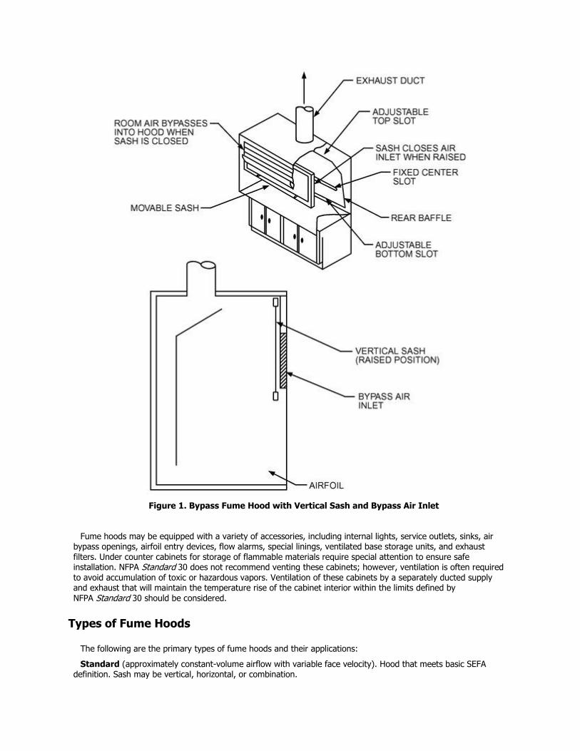
Figure 1. Bypass Fume Hood with Vertical Sash and Bypass Air Inlet
Fume hoods may be equipped with a variety of accessories, including internal lights, service outlets, sinks, air bypass openings, airfoil entry devices, flow alarms, special linings, ventilated base storage units, and exhaust filters. Under counter cabinets for storage of flammable materials require special attention to ensure safe installation. NFPA Standard 30 does not recommend venting these cabinets; however, ventilation is often required
to avoid accumulation of toxic or hazardous vapors. Ventilation of these cabinets by a separately ducted supply and exhaust that will maintain the temperature rise of the cabinet interior within the limits defined by NFPA Standard 30 should be considered.
Types of Fume Hoods
The following are the primary types of fume hoods and their applications:
Standard (approximately constant-volume airflow with variable face velocity). Hood that meets basic SEFA definition. Sash may be vertical, horizontal, or combination.
Application: Research laboratories—frequent or continuous use. Moderate to highly hazardous processes;
varying procedures.
Bypass (approximately constant-volume airflow). Standard vertical sash hood modified with openings above and below the sash. The openings are sized to minimize the change in the face velocity, which is generally to 3 or 4 times the full-open velocity, as the sash is lowered.
Application: Research laboratories—frequent or continuous use. Moderate to highly hazardous processes; varying procedures.
Variable Volume (constant face velocity). Hood has an opening or bypass designed to provide a prescribed minimum air intake when the sash is closed and an exhaust system designed to vary airflow in accordance with sash opening. Sash may be vertical, horizontal, or a combination of both.
Application: Research laboratories—frequent or continuous use. Moderate to highly hazardous processes; varying procedures.
Auxiliary Air (approximately constant-volume airflow). A plenum above the face receives air from a secondary air supply that provides partially conditioned or unconditioned outdoor air.
Application: Research laboratories—frequent or continuous use. Moderate to highly hazardous processes; varying procedures. Note: Many organizations restrict the use of this type of hood.
Low or Reduced Flow (approximately constant-volume airflow with variable face velocity). These hoods are designed to provide containment at lower average face velocities.
Application: Research laboratories—frequent or continuous use. Moderate to highly hazardous processes; varying procedures.
Process (approximately constant-volume airflow with approximately constant face velocity). Standard hood with a fixed opening and without a sash. By some definitions, this is not a fume hood. Considered a ventilated enclosure.
Application: Process laboratories—intermittent use. Low-hazard processes; known procedures.
Radioisotope. Standard hood with special integral work surface, linings impermeable to radioactive materials, and structure strong enough to support lead shielding bricks. The interior must be constructed to prevent radioactive material buildup and allow complete cleaning. Ductwork should have flanged neoprene gasketed joints with quick-disconnect fasteners that can be readily dismantled for decontamination. High-efficiency particulate air
(HEPA) and/or charcoal filters may be needed in exhaust duct.
Application: Process and research laboratories using radioactive isotopes.
Perchloric Acid. Standard hood with special integral work surfaces, coved corners, and non-organic lining materials. Perchloric acid is an extremely active oxidizing agent. Its vapors can form unstable deposits in the ductwork that present a potential explosion hazard. To alleviate this hazard, the exhaust system must be equipped with an internal water washdown and drainage system, and the ductwork must be constructed of smooth, impervious, cleanable materials that are resistant to acid attack. The internal washdown system must completely flush the ductwork, exhaust fan, discharge stack, and fume hood inner surfaces. Ductwork should be kept as short as possible with minimum elbows. Perchloric acid exhaust systems with longer duct runs may need a zoned washdown system to avoid water flow rates in excess of the capacity to drain water from the hood. Because perchloric acid is an extremely active oxidizing agent, organic materials should not be used in the exhaust system in places such as joints and gaskets. Ducts should be constructed of a stainless steel material, with a chromium and nickel content not less than that of 316 stainless steel, or of a suitable nonmetallic material. Joints should be welded and ground smooth. A perchloric acid exhaust system should only be used for work involving perchloric acid.
Application: Process and research laboratories using perchloric acid. Mandatory use because of explosion hazard.
California. Special hood with sash openings on multiple sides (usually horizontal).
Application: For enclosing large and complex research apparatus that require access from two or more sides.
Floor-Mounted Hood (Walk-In). Standard hood with sash openings to the floor. Sash can be either horizontal or vertical.
Application: For enclosing large or complex research apparatus. Not designed for personnel to enter while
operations are in progress.
Distillation. Standard fume hood with extra depth and 1/3- to 1/2-height benches.
Application: Research laboratory. For enclosing tall distillation apparatus.
Canopy. Open hood with an overhead capture structure.
Application: Not a true fume hood. Useful for heat or water vapor removal from some work areas. Not to be substituted for a fume hood. Not recommended when workers must bend over the source of heat or water vapor.
Fume Hood Sash Configurations
The work opening has operable glass sash(es) for observation and shielding. A sash may be vertically operable, horizontally operable, or a combination of both. A vertically operable sash can incorporate single or multiple vertical panels. A horizontally operable sash incorporates multiple panels that slide in multiple tracks, allowing the open area to be positioned across the face of the hood. The combination of a horizontally operable sash mounted
within a single vertically operable sash section allows the entire hood face to be opened for setup. Then the opening area can be limited by closing the vertical panel, with only the horizontally sliding sash sections used during experimentation. Either multiple vertical sash sections or the combination sash arrangement allow the use of larger fume hoods with limited opening areas, resulting in reduced exhaust airflow requirements. Fume hoods with vertically rising sash sections should include provisions around the sash to prevent the bypass of ceiling plenum air into the fume hood.
Fume Hood Performance
Containment of hazards in a fume hood is based on the principle that a flow of air entering at the face of the fume hood, passing through the enclosure, and exiting at the exhaust port prevents the escape of airborne contaminants from the hood into the room.
The following variables affect the performance of the fume hood:
Face velocity
Size of face opening
Sash position
Shape and configuration of entrance
Shape of any intermediate posts
Inside dimensions and location of work area relative to face area
Location of service fittings inside the fume hood
Size and number of exhaust ports
Back baffle and exhaust plenum arrangement
Bypass arrangement, if applicable.
Auxiliary air supply, if applicable
Arrangement and type of replacement supply air outlets
Air velocities near the hood
Distance from openings to spaces outside the laboratory
Movements of the researcher within the hood opening
Location, size, and type of research apparatus placed in the hood
Distance from the apparatus to the researcher’s breathing zone
Air Currents. Air currents external to the fume hood can jeopardize the hood’s effectiveness and expose the
researcher to materials used in the hood. Detrimental air currents can be produced by
Air supply distribution patterns in the laboratory
Movements of the researcher
People walking past the fume hood
Thermal convection
Opening of doors and windows
Caplan and Knutson (1977, 1978) conducted tests to determine the interactions between room air motion and fume hood capture velocities with respect to the spillage of contaminants into the room. Their tests indicated that the effect of room air currents is significant and of the same order of magnitude as the effect of the hood face velocity. Consequently, improper design and/or installation of the replacement air supply can lower the performance of the fume hood.
Disturbance velocities at the face of the hood should be no more than one-half and preferably one-third the face
velocity of the hood. This is an especially critical factor in designs that use low face velocities. For example, a fume hood with a face velocity of 100 fpm could tolerate a maximum disturbance velocity of 50 fpm. If the design face velocity were 60 fpm, the maximum disturbance velocity would be 30 fpm.
To the extent possible, the fume hood should be located so that traffic flow past the hood is minimal. Also, the fume hood should be placed to avoid any air currents generated from the opening of windows and doors. To ensure the optimum placement of the fume hoods, the HVAC system designer must take an active role early in the design process.
Use of Auxiliary Air Fume Hoods. AIHA Standard Z9.5 discourages the use of auxiliary air fume hoods. These hoods incorporate an air supply at the fume hood to reduce the amount of room air exhausted. The following difficulties and installation criteria are associated with auxiliary air fume hoods:
The auxiliary air supply must be introduced outside the fume hood to maintain appropriate velocities past the researcher.
The flow pattern of the auxiliary air must not degrade the containment performance of the fume hood.
The volume of auxiliary air must not be enough to degrade the fume hood’s containment performance.
Auxiliary air must be conditioned to avoid blowing cold air on the researcher; often the air must be cooled to maintain the required temperature and humidity within the hood. Auxiliary air can introduce additional heating and cooling loads in the laboratory.
Only vertical sash should be used in the hood.
Controls for the exhaust, auxiliary, and supply airstreams must be coordinated.
Additional coordination of utilities during installation is required to avoid spatial conflicts caused by the additional duct system.
Humidity control can be difficult: Unless auxiliary air is cooled to the dew point of the specified internal conditions, there is some degradation of humidity control; however, if such cooling is done, the rationale for using auxiliary air has been eliminated.
Fume Hood Performance Criteria. ASHRAE Standard 110 describes a quantitative method of determining the containment performance of a fume hood. The method requires the use of a tracer gas and instruments to measure the amount of tracer gas that enters the breathing zone of a mannequin; this simulates the containment capability of the fume hood as a researcher conducts operations in the hood. The following tests are commonly used to judge the performance of the fume hood: (1) face velocity test, (2) flow visualization test, (3) large-volume flow visualization, (4) tracer gas test, and (5) sash movement test. These tests should be performed under the following conditions:
Usual amount of research equipment in the hood; the room air balance set
Doors and windows in their normal positions
Fume hood sash set in varying positions to simulate both static and dynamic performance
All fume hoods should be tested annually and their performance certified. The following descriptions partially summarize the test procedures. ASHRAE Standard 110 provides specific requirements and procedures.
Face Velocity Test
The safety officer, engineer, and the researcher should determine the desired face velocity. The velocity is a balance between safe operation of the fume hood, airflow needed for the hood operation, and energy cost. Face velocity measurements are taken on a vertical/horizontal grid, with each measurement point representing not more than 1 ft2. The measurements should be taken with a device that is accurate in the intended operating range, and an instrument holder should be used to improve accuracy. Computerized multipoint grid measurement devices provide the greatest accuracy.
Flow Visualization
1. Swab a strip of titanium tetrachloride along both walls and the hood deck in a line parallel to the hood face and 6 in. back into the hood. Caution: Titanium tetrachloride forms smoke and is corrosive to the skin and extremely irritating to the eyes and respiratory system.
2. Swab an 8 in. circle on the back of the hood. Define air movement toward the face of the hood as reverse airflow and lack of movement as dead airspace.
3. Swab the work surface of the hood, being sure to swab lines around all equipment in the hood. All smoke should be carried to the back of the hood and out.
4. Test the operation of the deck airfoil bypass by running the cotton swab under the airfoil.
5. Before going to the next test, move the cotton swab around the face of the hood; if there is any outfall, the exhaust capacity test (large capacity flow visualization) should not be made.
Large-Volume Flow Visualization
Appropriate measures should be taken prior to undertaking a smoke test to avoid accidental activation of the building’s smoke detection system.
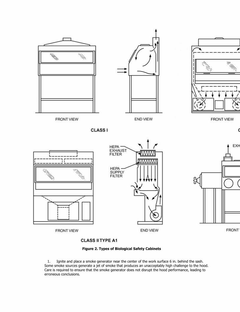
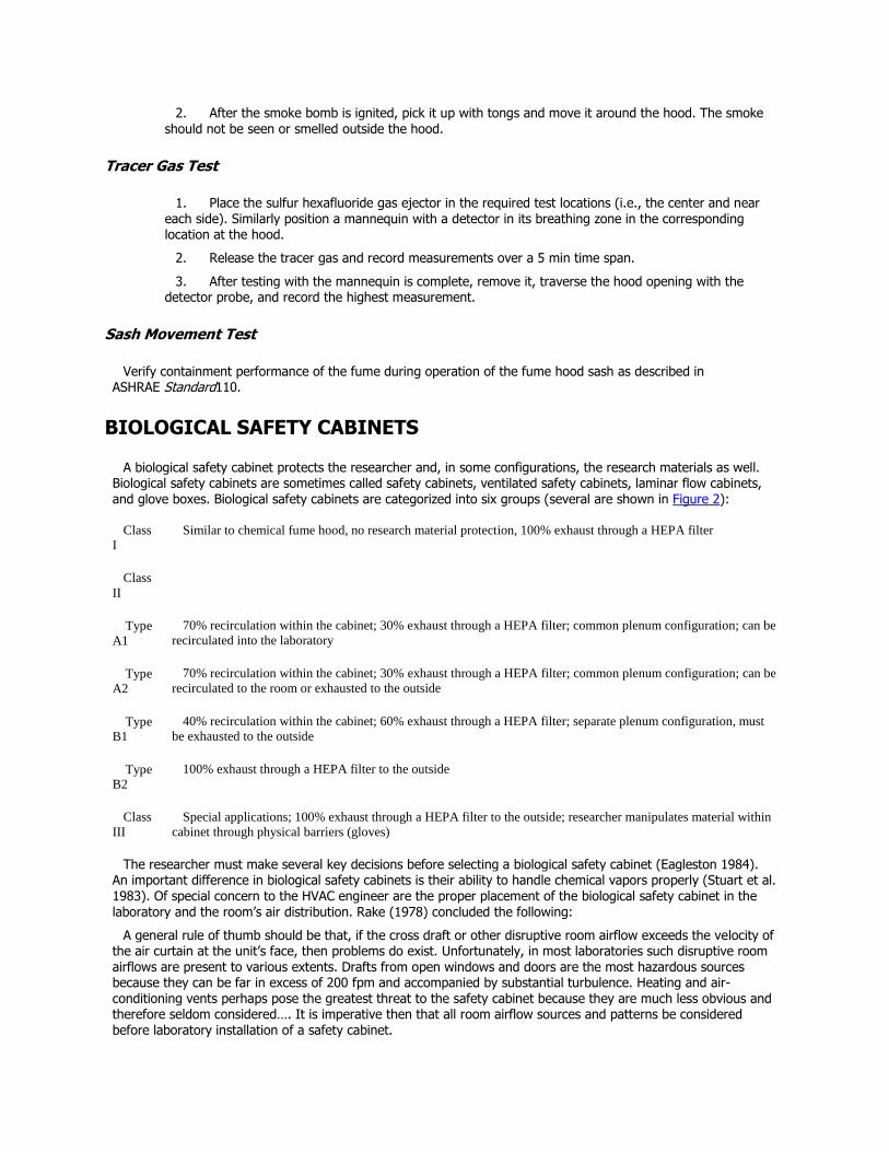
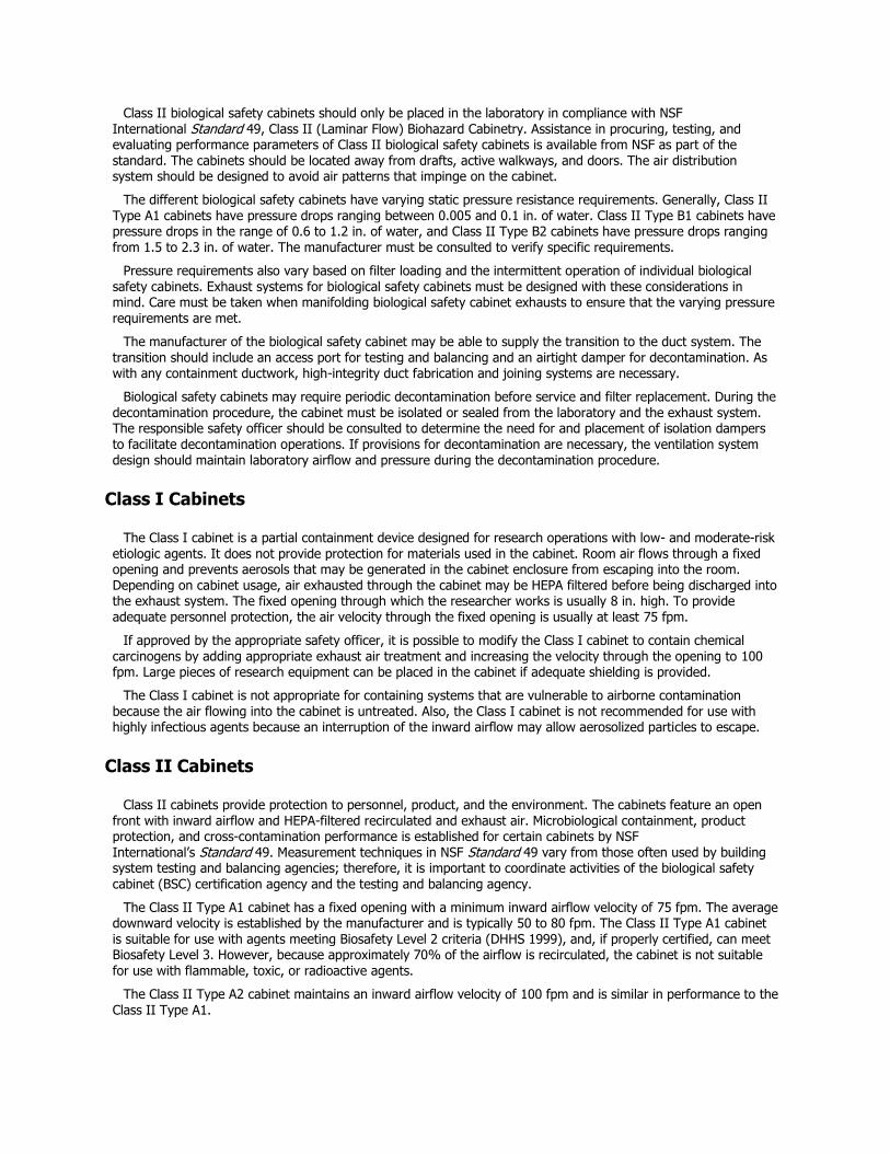
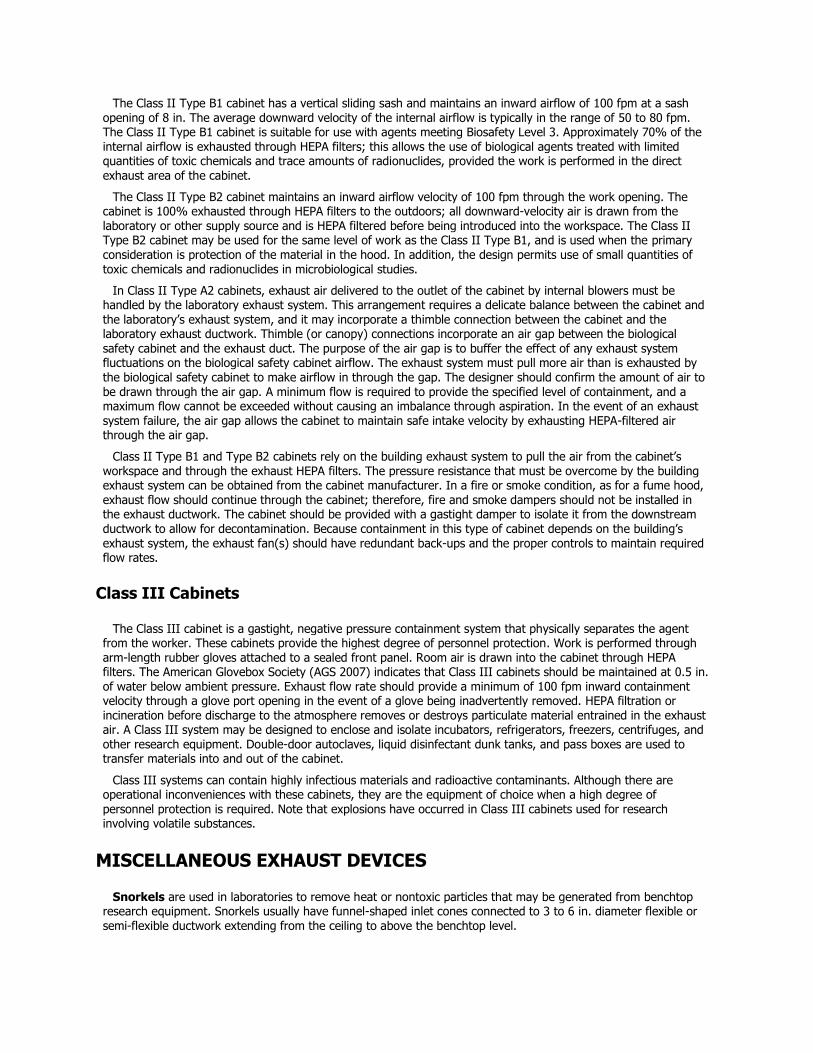
Figure 2. Types of Biological Safety Cabinets
1. Ignite and place a smoke generator near the center of the work surface 6 in. behind the sash. Some smoke sources generate a jet of smoke that produces an unacceptably high challenge to the hood. Care is required to ensure that the smoke generator does not disrupt the hood performance, leading to erroneous conclusions.
2. After the smoke bomb is ignited, pick it up with tongs and move it around the hood. The smoke
should not be seen or smelled outside the hood.
Tracer Gas Test
1. Place the sulfur hexafluoride gas ejector in the required test locations (i.e., the center and near each side). Similarly position a mannequin with a detector in its breathing zone in the corresponding location at the hood.
2. Release the tracer gas and record measurements over a 5 min time span.
3. After testing with the mannequin is complete, remove it, traverse the hood opening with the detector probe, and record the highest measurement.
Sash Movement Test
Verify containment performance of the fume during operation of the fume hood sash as described in ASHRAE Standard110.
BIOLOGICAL SAFETY CABINETS
A biological safety cabinet protects the researcher and, in some configurations, the research materials as well. Biological safety cabinets are sometimes called safety cabinets, ventilated safety cabinets, laminar flow cabinets, and glove boxes. Biological safety cabinets are categorized into six groups (several are shown in Figure 2):
Class
I
Similar to chemical fume hood, no research material protection, 100% exhaust through a HEPA filter
Class
II
Type
A1
70% recirculation within the cabinet; 30% exhaust through a HEPA filter; common plenum configuration; can be
recirculated into the laboratory
Type
A2
70% recirculation within the cabinet; 30% exhaust through a HEPA filter; common plenum configuration; can be
recirculated to the room or exhausted to the outside
Type B1
40% recirculation within the cabinet; 60% exhaust through a HEPA filter; separate plenum configuration, must
be exhausted to the outside
Type B2
100% exhaust through a HEPA filter to the outside
Class
III
Special applications; 100% exhaust through a HEPA filter to the outside; researcher manipulates material within
cabinet through physical barriers (gloves)
The researcher must make several key decisions before selecting a biological safety cabinet (Eagleston 1984). An important difference in biological safety cabinets is their ability to handle chemical vapors properly (Stuart et al. 1983). Of special concern to the HVAC engineer are the proper placement of the biological safety cabinet in the laboratory and the room’s air distribution. Rake (1978) concluded the following:
A general rule of thumb should be that, if the cross draft or other disruptive room airflow exceeds the velocity of the air curtain at the unit’s face, then problems do exist. Unfortunately, in most laboratories such disruptive room airflows are present to various extents. Drafts from open windows and doors are the most hazardous sources because they can be far in excess of 200 fpm and accompanied by substantial turbulence. Heating and air-conditioning vents perhaps pose the greatest threat to the safety cabinet because they are much less obvious and therefore seldom considered…. It is imperative then that all room airflow sources and patterns be considered before laboratory installation of a safety cabinet.
Class II biological safety cabinets should only be placed in the laboratory in compliance with NSF
International Standard 49, Class II (Laminar Flow) Biohazard Cabinetry. Assistance in procuring, testing, and evaluating performance parameters of Class II biological safety cabinets is available from NSF as part of the standard. The cabinets should be located away from drafts, active walkways, and doors. The air distribution system should be designed to avoid air patterns that impinge on the cabinet.
The different biological safety cabinets have varying static pressure resistance requirements. Generally, Class II Type A1 cabinets have pressure drops ranging between 0.005 and 0.1 in. of water. Class II Type B1 cabinets have pressure drops in the range of 0.6 to 1.2 in. of water, and Class II Type B2 cabinets have pressure drops ranging from 1.5 to 2.3 in. of water. The manufacturer must be consulted to verify specific requirements.
Pressure requirements also vary based on filter loading and the intermittent operation of individual biological safety cabinets. Exhaust systems for biological safety cabinets must be designed with these considerations in mind. Care must be taken when manifolding biological safety cabinet exhausts to ensure that the varying pressure requirements are met.
The manufacturer of the biological safety cabinet may be able to supply the transition to the duct system. The transition should include an access port for testing and balancing and an airtight damper for decontamination. As with any containment ductwork, high-integrity duct fabrication and joining systems are necessary.
Biological safety cabinets may require periodic decontamination before service and filter replacement. During the decontamination procedure, the cabinet must be isolated or sealed from the laboratory and the exhaust system. The responsible safety officer should be consulted to determine the need for and placement of isolation dampers to facilitate decontamination operations. If provisions for decontamination are necessary, the ventilation system design should maintain laboratory airflow and pressure during the decontamination procedure.
Class I Cabinets
The Class I cabinet is a partial containment device designed for research operations with low- and moderate-risk etiologic agents. It does not provide protection for materials used in the cabinet. Room air flows through a fixed opening and prevents aerosols that may be generated in the cabinet enclosure from escaping into the room. Depending on cabinet usage, air exhausted through the cabinet may be HEPA filtered before being discharged into the exhaust system. The fixed opening through which the researcher works is usually 8 in. high. To provide adequate personnel protection, the air velocity through the fixed opening is usually at least 75 fpm.
If approved by the appropriate safety officer, it is possible to modify the Class I cabinet to contain chemical carcinogens by adding appropriate exhaust air treatment and increasing the velocity through the opening to 100 fpm. Large pieces of research equipment can be placed in the cabinet if adequate shielding is provided.
The Class I cabinet is not appropriate for containing systems that are vulnerable to airborne contamination because the air flowing into the cabinet is untreated. Also, the Class I cabinet is not recommended for use with highly infectious agents because an interruption of the inward airflow may allow aerosolized particles to escape.
Class II Cabinets
Class II cabinets provide protection to personnel, product, and the environment. The cabinets feature an open front with inward airflow and HEPA-filtered recirculated and exhaust air. Microbiological containment, product protection, and cross-contamination performance is established for certain cabinets by NSF International’s Standard 49. Measurement techniques in NSF Standard 49 vary from those often used by building system testing and balancing agencies; therefore, it is important to coordinate activities of the biological safety
cabinet (BSC) certification agency and the testing and balancing agency.
The Class II Type A1 cabinet has a fixed opening with a minimum inward airflow velocity of 75 fpm. The average downward velocity is established by the manufacturer and is typically 50 to 80 fpm. The Class II Type A1 cabinet is suitable for use with agents meeting Biosafety Level 2 criteria (DHHS 1999), and, if properly certified, can meet Biosafety Level 3. However, because approximately 70% of the airflow is recirculated, the cabinet is not suitable for use with flammable, toxic, or radioactive agents.
The Class II Type A2 cabinet maintains an inward airflow velocity of 100 fpm and is similar in performance to the Class II Type A1.
The Class II Type B1 cabinet has a vertical sliding sash and maintains an inward airflow of 100 fpm at a sash
opening of 8 in. The average downward velocity of the internal airflow is typically in the range of 50 to 80 fpm. The Class II Type B1 cabinet is suitable for use with agents meeting Biosafety Level 3. Approximately 70% of the internal airflow is exhausted through HEPA filters; this allows the use of biological agents treated with limited quantities of toxic chemicals and trace amounts of radionuclides, provided the work is performed in the direct exhaust area of the cabinet.
The Class II Type B2 cabinet maintains an inward airflow velocity of 100 fpm through the work opening. The cabinet is 100% exhausted through HEPA filters to the outdoors; all downward-velocity air is drawn from the laboratory or other supply source and is HEPA filtered before being introduced into the workspace. The Class II Type B2 cabinet may be used for the same level of work as the Class II Type B1, and is used when the primary consideration is protection of the material in the hood. In addition, the design permits use of small quantities of toxic chemicals and radionuclides in microbiological studies.
In Class II Type A2 cabinets, exhaust air delivered to the outlet of the cabinet by internal blowers must be handled by the laboratory exhaust system. This arrangement requires a delicate balance between the cabinet and the laboratory’s exhaust system, and it may incorporate a thimble connection between the cabinet and the laboratory exhaust ductwork. Thimble (or canopy) connections incorporate an air gap between the biological
safety cabinet and the exhaust duct. The purpose of the air gap is to buffer the effect of any exhaust system fluctuations on the biological safety cabinet airflow. The exhaust system must pull more air than is exhausted by the biological safety cabinet to make airflow in through the gap. The designer should confirm the amount of air to be drawn through the air gap. A minimum flow is required to provide the specified level of containment, and a maximum flow cannot be exceeded without causing an imbalance through aspiration. In the event of an exhaust system failure, the air gap allows the cabinet to maintain safe intake velocity by exhausting HEPA-filtered air through the air gap.
Class II Type B1 and Type B2 cabinets rely on the building exhaust system to pull the air from the cabinet’s workspace and through the exhaust HEPA filters. The pressure resistance that must be overcome by the building exhaust system can be obtained from the cabinet manufacturer. In a fire or smoke condition, as for a fume hood, exhaust flow should continue through the cabinet; therefore, fire and smoke dampers should not be installed in the exhaust ductwork. The cabinet should be provided with a gastight damper to isolate it from the downstream ductwork to allow for decontamination. Because containment in this type of cabinet depends on the building’s exhaust system, the exhaust fan(s) should have redundant back-ups and the proper controls to maintain required flow rates.
Class III Cabinets
The Class III cabinet is a gastight, negative pressure containment system that physically separates the agent from the worker. These cabinets provide the highest degree of personnel protection. Work is performed through arm-length rubber gloves attached to a sealed front panel. Room air is drawn into the cabinet through HEPA filters. The American Glovebox Society (AGS 2007) indicates that Class III cabinets should be maintained at 0.5 in. of water below ambient pressure. Exhaust flow rate should provide a minimum of 100 fpm inward containment velocity through a glove port opening in the event of a glove being inadvertently removed. HEPA filtration or incineration before discharge to the atmosphere removes or destroys particulate material entrained in the exhaust air. A Class III system may be designed to enclose and isolate incubators, refrigerators, freezers, centrifuges, and other research equipment. Double-door autoclaves, liquid disinfectant dunk tanks, and pass boxes are used to transfer materials into and out of the cabinet.
Class III systems can contain highly infectious materials and radioactive contaminants. Although there are operational inconveniences with these cabinets, they are the equipment of choice when a high degree of
personnel protection is required. Note that explosions have occurred in Class III cabinets used for research involving volatile substances.
MISCELLANEOUS EXHAUST DEVICES
Snorkels are used in laboratories to remove heat or nontoxic particles that may be generated from benchtop research equipment. Snorkels usually have funnel-shaped inlet cones connected to 3 to 6 in. diameter flexible or semi-flexible ductwork extending from the ceiling to above the benchtop level.
Typically, canopy hoods are used to remove heat or moisture generated by a specific piece of research
apparatus (e.g., steam sterilizer) or process. Canopy hoods cannot contain hazardous fumes adequately to protect the researcher.Benchtop slots are used to remove nontoxic particles or fumes that may be generated by benchtop equipment.
Often, hoods are installed over weigh stations to contain and minimize disturbances from room air currents.
LAMINAR FLOW CLEAN BENCHES
Laminar flow clean benches are available in two configurations: horizontal (crossflow) and vertical (downflow). Both configurations filter the supply air and usually discharge the air out the front opening into the room. Clean benches protect the experiment or product but do not protect the researcher; therefore, they should not be used with any potentially hazardous or allergenic substances. Clean benches are not recommended for any work involving hazardous biological, chemical, or radionuclide materials.
COMPRESSED GAS STORAGE AND VENTILATION
Gas Cylinder Closets
Most laboratory buildings require storage closets for cylinders of compressed gases, which may be inert, flammable, toxic, corrosive, or poisonous. The requirements for storage and ventilation are covered in building codes and NFPA standards and codes. Water sprinklers are usually required, but other types of fire suppression may be needed based on the gases stored. Explosion containment requires a separate structural study, and closets generally require an outside wall for venting. One design used by a large chemical manufacturer to house gases with explosion potential specifies a completely welded 0.25 in.steel inner liner for the closet, heavy-duty door latches designed to hold under the force of an internal explosion, and venting out the top of the closet.
Closet temperature should not exceed 125°F per NFPA Standard 55. Ventilation for cylinder storage is established in NFPAStandard 55 at a minimum of 1 cfm/ft2. Ventilation rates can be calculated by determining both the amount of gas that could be released by complete failure of the cylinder outlet piping connection and the time the release would take, and then finding the dilution airflow required to reduce any hazard below the maximum allowable limit.
Ventilation air is usually exhausted from the closet; makeup air comes from the surrounding space through openings in and around the door or through a transfer duct. That makeup air must be added into the building air balance. Ventilation for a closet to contain materials with explosion potential must be carefully designed, with safety considerations taken into account. NFPA Standard 68 is a reference on explosion venting.
Cylinder closet exhausts should be connected through a separate duct system to a dedicated exhaust fan or to a manifold system in which constant volume can be maintained under any possible manifold condition. A standby source of emergency power should be considered for the exhaust system fan(s).
Gas Cylinder Cabinets
Compressed gases that present a physical or health hazard are often placed in premanufactured gas cylinder cabinets. Gas cylinder cabinets are available for single-, dual-, or triple-cylinder configurations and are commonly equipped with valve manifolds, fire sprinklers, exhaust connections, access openings, and operational and safety
controls. The engineer must fully understand safety, material, and purity requirements associated with specific compressed gases when designing and selecting cylinder cabinets and the components that make up the compressed gas handling system.
Exhaust from the gas cylinder cabinets is provided at a high rate. Air is drawn into the gas cylinder cabinet from the surrounding space through a filtered opening, usually on the lower front of the cylinder cabinet. Depending on the specific gas in the cabinet, the exhaust system may require emission control equipment and a source of emergency power.
LABORATORY VENTILATION
The total airflow rate for a laboratory is dictated by one of the following:
Total amount of exhaust from containment and exhaust devices
Cooling required to offset internal heat gains
Minimum ventilation rate requirements
Fume hood exhaust requirements (including evaluation of alternate sash configurations as described in the section on Fume Hoods) must be determined in consultation with the safety officers. The HVAC engineer must determine the expected heat gains from the research equipment after consulting with the research staff (see the section on Internal Thermal Considerations).
Minimum ventilation rates should be established that provide a safe and healthy environment under normal and expected operating conditions. The dilution ventilation provided by this airflow is no substitute for the containment performance of a laboratory fume hood or other primary containment device regardless of the room ventilation rate. The appropriate ventilation rate for clearing a room of fugitive emissions or spills varies significantly based on the amount of release, the chemical’s evaporation rate and hazard level, and ventilation system effectiveness.
Fixed minimum airflow rates in the range of 6 to 12 air changes per hour (ach) when the space is occupied have been used in the past. However, recent university research (Klein et al. 2009) showed a significant increase in dilution and clearing performance by increasing the air change rate from 6 to 8 ach with diminishing returns above 12 ach. Similarly, CFD research (Schuyler 2009) showed that increasing the lab’s dilution ventilation rate from 4 to 8 ach reduced the background contaminant level by greater than a factor of 10. This indicates that minimum ventilation rates at the lower end of the 6 to 12 ach range may not be appropriate for all laboratories. Minimum ventilation rates should be established on a room-by-room basis considering the hazard level of materials expected to be used in the room and the operation and procedures to be performed. As the operation, materials, and hazard level of a room change, an increase or decrease in the minimum ventilation rate should be evaluated.
Active sensing of air quality in individual laboratories (Sharp 2010) is an alternative approach for dealing with the variability of appropriate ventilation rates, particularly when energy efficiency is important or when less may be known about the hazard level. With this approach, the minimum airflow rate is varied based on sensing the laboratory’s actual air quality level or “air cleanliness.” Sensors used to determine air quality should be evaluated for their ability to detect chemicals being used in the space. When air contaminants are sensed in the laboratory above a given threshold, the minimum air change rate is increased proportionally to an appropriate level to purge the room. When the air is “clean” and contaminants are below the previously mentioned threshold, lower
minimum airflow rates may be appropriate. Extensive studies of lab room environmental conditions (Sharp 2010) have shown that the air in labs is typically “clean” over 98% of the time.
The maximum airflow rate for the laboratory should be reviewed to ensure that appropriate supply air delivery methods are chosen such that supply airflows do not impede the performance of the exhaust devices. Laboratory ventilation systems can be arranged for either constant-volume or variable-volume airflow. The specific type should be selected with the research staff, safety officers, and maintenance personnel. Special attention should be given to unique areas such as glass washing areas, hot and cold environmental rooms and labs, fermentation rooms, and cage washing rooms. Emergency power systems to operate the laboratory ventilation equipment should be considered based on hazard assessment or other specific requirements. Care should be taken to ensure that an adequate amount of makeup air is available whenever exhaust fans are operated on emergency power. Additional selection criteria are described in the sections on Hazard Assessment and Operation and Maintenance.
Usage Factor
In many laboratories, all hoods and safety cabinets are seldom needed at the same time. A system usage factor
represents the maximum number of exhaust devices with sashes open or in use simultaneously. The system usage factor depends on the
Type and size of facility
Total number of fume hoods
Number of fume hoods per researcher
Airflow diversity
Type of fume hood controls
Fume hood sash configuration and minimum airflow required
Type of laboratory ventilation systems
Number of devices that must operate continuously due to chemical storage requirements or contamination prevention
Number of current and projected research programs
Usage factors should be applied carefully when sizing equipment. For example, teaching laboratories may have a usage factor of 100% when occupied by students.
If too low a usage factor is selected, design airflow and containment performance cannot be maintained. It is usually expensive and disruptive to add capacity to an operating laboratory’s supply or exhaust system. Detailed discussions with research staff are required to ascertain maximum usage factors as well as likely future requirements.
Noise
Noise level in the laboratory should be considered at the beginning of the design so that noise criterion (NC) levels suitable for scientific work can be achieved. For example, at the NIH, sound levels of NC 40 to 45 (including fume hoods) are required in regularly occupied laboratories. The requirement is relaxed to NC 55 for instrument rooms. If noise criteria are not addressed as part of the design, NC levels can be 65 or greater, which is unacceptable to most occupants. Sound generated by the building HVAC equipment should be evaluated to ensure that excessive levels do not escape to the outdoors. Remedial correction of excessive sound levels can be difficult and expensive. See Chapter 48 for more information.
SUPPLY AIR SYSTEMS
Supply air systems for laboratories provide the following:
Thermal comfort for occupants
Minimum and maximum airflow rates
Replacement for air exhausted through fume hoods, biological safety cabinets, or other exhaust devices
Space pressurization control
Environmental control to meet process or experimental criteria
The design parameters must be well defined for selection, sizing, and layout of the supply air system. Installation and setup should be verified as part of the commissioning process. Design parameters are covered in the section on Design Parameters, and commissioning is covered in the section on Commissioning. Laboratories in which chemicals and compressed gases are used generally require nonrecirculating or 100% outdoor air supply systems. The selection of 100% outdoor air supply systems versus return air systems should be made as part of the hazard assessment process, which is discussed in the section on Hazard Assessment. A 100% outdoor air system must have a very wide range of heating and cooling capacity, which requires special design and control.
Supply air systems for laboratories include constant-volume, high-low volume, and variable-volume systems that incorporate either single-duct reheat or dual-duct configurations, with distribution through low-, medium-, or high-
pressure ductwork.
Filtration
Filtration for the air supply depends on the requirements of the laboratory. Conventional chemistry and physics laboratories commonly use 85% dust spot efficient filters (ASHRAE Standard 52.1). Biological and biomedical laboratories usually require 85 to 95% dust spot efficient filtration. HEPA filters should be provided for spaces where research materials or animals are particularly susceptible to contamination from external sources. HEPA filtration of the supply air is necessary for such applications as environmental studies, studies involving specific
pathogen-free research animals or nude mice, dust-sensitive work, and electronic assemblies. In many instances,
biological safety cabinets or laminar flow clean benches (which are HEPA filtered) may be used rather than HEPA filtration for the entire laboratory.
Air Distribution
Air supplied to a laboratory must be distributed to keep temperature gradients and air currents to minimum. Air outlets (preferably nonaspirating diffusers) must not discharge into the face of a fume hood, a biological safety cabinet, or an exhaust device. Acceptable room air velocities are covered in the sections on Fume Hoods and Biological Safety Cabinets. Special techniques and diffusers are often needed to introduce the large air quantities required for a laboratory without creating disturbances at exhaust devices.
EXHAUST SYSTEMS
Laboratory exhaust systems remove air from containment devices and from the laboratory itself. The exhaust
system must be controlled and coordinated with the supply air system to maintain correct pressurization. Additional information on the control of exhaust systems is included in the section on Control. Design parameters must be well defined for selection, sizing, and layout of the exhaust air system. Installation and setup should be verified as part of the commissioning process. See the sections on Design Parameters and Commissioning. Laboratory exhaust systems should be designed for high reliability and ease of maintenance. This can be achieved by providing multiple exhaust fans and by sectionalizing equipment so that maintenance work may be performed on an individual exhaust fan while the system is operating. Another option is to use predictive maintenance procedures to detect problems prior to failure and to allow for scheduled shutdowns for maintenance. To the extent possible, components of exhaust systems should allow maintenance without exposing maintenance personnel to the exhaust airstream. Access to filters and the need for bag-in, bag-out filter housings should be considered during the design process.
Depending on the effluent of the processes being conducted, the exhaust airstream may require filtration, scrubbing, or other emission control to remove environmentally hazardous materials. Any need for emission control devices must be determined early in the design so that adequate space can be provided and cost implications can be recognized.
Types of Exhaust Systems
Laboratory exhaust systems can be constant-volume, variable-volume, or high-low volume systems with low-, medium-, or high-pressure ductwork, depending on the static pressure of the system. Each fume hood may have its own exhaust fan, or fume hoods may be manifolded and connected to one or more common central exhaust fans. Maintenance, functional requirements, and safety must be considered when selecting an exhaust system. Part of the hazard assessment analysis is to determine the appropriateness of variable-volume systems and the need for individually ducted exhaust systems. Laboratories with a high hazard potential should be analyzed carefully before variable-volume airflow is selected, because minimum air flow requirements could affect the design criteria.Airflow monitoring and pressure-independent control may be required even with constant-volume systems. In addition, fume hoods or other devices in which extremely hazardous or radioactive materials are used should receive special review to determine whether they should be connected to a manifolded exhaust system.
All exhaust devices installed in a laboratory are seldom used simultaneously at full capacity. This allows the HVAC engineer to conserve energy and, potentially, to reduce equipment capacities by installing a variable-volume
system that includes an overall system usage factor. Selection of an appropriate usage factor is discussed in the section on Usage Factor.
Manifolded Exhaust Systems. These can be classified as pressure-dependent or pressure-independent. Pressure-dependent systems are constant-volume only and incorporate manually adjusted balancing dampers for each exhaust device. If an additional fume hood is added to a pressure-dependent exhaust system, the entire system must be rebalanced, and the speed of the exhaust fans may need to be adjusted. Because pressure-independent systems are more flexible, pressure-dependent systems are not common in current designs.
A pressure-independent system can be constant-volume, variable-volume, or a mix of the two. It
incorporates pressure-independent volume regulators with each device. The system offers two advantages: (1) flexibility to add exhaust devices without having to rebalance the entire system and (2) variable-volume control.
The volume regulators can incorporate either direct measurement of the exhaust airflow rate or positioning of a calibrated pressure-independent air valve. The input to the volume regulator can be (1) a manual or timed switch to index the fume hood airflow from minimum to operational airflow, (2) sash position sensors, (3) fume hood cabinet pressure sensors, or (4) velocity sensors. The section on Control covers this topic in greater detail. Running many exhaust devices into the manifold of a common exhaust system offers the following potential benefits:
Lower ductwork cost
Fewer pieces of equipment to operate and maintain
Fewer roof penetrations and exhaust stacks
Opportunity for energy recovery
Centralized locations for exhaust discharge
Ability to take advantage of exhaust system diversity
Ability to provide a redundant exhaust system by adding one spare fan per manifold
Individually Ducted Exhaust Systems. These comprise a separate duct, exhaust fan, and discharge stack for each exhaust device or laboratory. The exhaust fan can be single-speed, multiple-speed, or variable-speed and can be configured for constant volume, variable volume, or a combination of the two. An individually ducted exhaust system has the following potential benefits:
Provision for installation of special exhaust filtration or treatment systems
Customized ductwork and exhaust fan corrosion control for specific applications
Provision for selected emergency power backup
Simpler initial balancing
Failure of an individual fan may affect smaller areas of the facility
Maintaining correct flow at each exhaust fan requires (1) periodic maintenance and balancing and (2) consideration of the flow rates with the fume hood sash in different positions. One problem encountered with individually ducted exhaust systems occurs when an exhaust fan is shut down. In this case, air can be drawn in reverse flow through the exhaust ductwork into the laboratory because the laboratory is maintained at a negative pressure.
A challenge in designing independently ducted exhaust systems for multistory buildings is to provide extra vertical ductwork, extra space, and other provisions for the future installation of additional exhaust devices. In multistory buildings, dedicated fire-rated shafts may be required from each floor to the penthouse or roof level. This issue should be evaluated in conjunction with the requirements of the relevant fire code. As a result, individually ducted exhaust systems (or vertically manifolded systems) consume greater floor space than horizontally manifolded systems. However, less height between floors may be required.
Ductwork Leakage
Ductwork should have low leakage rates and should be tested to confirm that the specified leakage rates have been attained. Leaks from positive pressure exhaust ductwork can contaminate the building. The design goal should be zero leakage from any positive-pressure exhaust ductwork. Designs that minimize the amount of positive-pressure ductwork are desirable. It is recommended (and required by some codes) that positive-pressure ductwork transporting potentially hazardous materials be located outside of the building. All positive-pressure ductwork should be of the highest possible integrity. The fan discharge should connect directly to the vertical discharge stack. Careful selection and proper installation of airtight flexible connectors at the exhaust fans are essential. Some feel that flexible connectors should be used on the exhaust fan inlet only. If flexible connectors are used on the discharge side of the exhaust fan, they must be of high quality and included on a preventative maintenance schedule because a connector failure could result in the leakage of hazardous fumes into the
equipment room. Another viewpoint contends that the discharge side of the exhaust fan should be hard connected
to the ductwork without the use of flexible connectors. The engineer should evaluate these details carefully. The potential for vibration and noise transmission must also be considered. Machine rooms that house exhaust fans should be ventilated to minimize exposure to exhaust effluent (e.g., leakage from the shaft openings of exhaust fans).
Containment Device Leakage
Leakage of the containment devices themselves must also be considered. For example, in vertical sash fume hoods, the clearance to allow sash movement creates an opening from the top of the fume hood into the ceiling space or area above. The air introduced through this leakage path also contributes to the exhaust airstream. The amount that such leakage sources contribute to the exhaust airflow depends on the fume hood design. Edge seals can be placed around sash tracks to minimize leaks. Although the volumetric flow of air exhausted through a fume hood is based on the actual face opening, appropriate allowances for air introduced through paths other than the face opening must be included.
Materials and Construction
The selection of materials and the construction of exhaust ductwork and fans depend on the following:
Nature of the effluents
Ambient temperature
Ambient relative humidity
Effluent temperature
Length and arrangement of duct runs
Constant or intermittent flow
Flame spread and smoke developed ratings
Duct velocities and pressures
Effluents may be classified generically as organic or inorganic chemical gases, vapors, fumes, or smoke; and qualitatively as acids, alkalis (bases), solvents, or oils. Exhaust system ducts, fans, dampers, flow sensors, and coatings are subject to (1) corrosion, which destroys metal by chemical or electrochemical action; (2) dissolution, which destroys materials such as coatings and plastics; and (3) melting, which can occur in certain plastics and coatings at elevated temperatures.
Common reagents used in laboratories include acids and bases. Common organic chemicals include acetone, ether, petroleum ether, chloroform, and acetic acid. The HVAC engineer should consult with the safety officer and scientists because the specific research to be conducted determines the chemicals used and therefore the necessary duct material and construction.
The ambient temperature in the space housing the ductwork and fans affects the condensation of vapors in the exhaust system. Condensation contributes to the corrosion of metals, and the chemicals used in the laboratory may further accelerate corrosion.
Ducts are less subject to corrosion when runs are short and direct, the flow is maintained at reasonable
velocities, and condensation is avoided. Horizontal ductwork may be more susceptible to corrosion if condensate accumulates in the bottom of the duct. Applications with moist airstreams (cage washers, sterilizers, etc.) may require condensate drains that are connected to chemical sewers. The design should include provisions to minimize joint or seam corrosion problems.
If flow through the ductwork is intermittent, condensate may remain for longer periods because it will not be able to reevaporate into the airstream. Moisture can also condense on the outside of ductwork exhausting cold environmental rooms.
Flame spread and smoke developed ratings, which are specified by codes or insurance underwriters, must also be considered when selecting duct materials. In determining the appropriate duct material and construction, the HVAC engineer should
Determine the types of effluents (and possibly combinations) handled by the exhaust system
Classify effluents as either organic or inorganic, and determine whether they occur in the gaseous, vapor, or liquid state
Classify decontamination materials
Determine the concentration of the reagents used and the temperature of the effluents at the hood exhaust port (this may be impossible in research laboratories)
Estimate the highest possible dew point of the effluent
Determine the ambient temperature of the space housing the exhaust system
Estimate the degree to which condensation may occur
Determine whether flow will be constant or intermittent (intermittent flow conditions may be improved by adding time delays to run the exhaust system long enough to dry the duct interior prior to shutdown)
Determine whether insulation, watertight construction, or sloped and drained ductwork are required
Select materials and construction most suited for the application
Considerations in selecting materials include resistance to chemical attack and corrosion, reaction to condensation, flame and smoke ratings, ease of installation, ease of repair or replacement, and maintenance costs.
Appropriate materials can be selected from standard references and by consulting with manufacturers of specific materials. Materials for chemical fume exhaust systems and their characteristics include the following:
Galvanized steel. Subject to acid and alkali attack, particularly at cut edges and under wet conditions; cannot be field welded without destroying galvanization; easily formed; low in cost.
Stainless steel. Subject to acid and chloride compound attack depending on the nickel and chromium content of the alloy. Relatively high in cost. The most common stainless steel alloys used for laboratory exhaust systems are 304 and 316. Cost increases with increasing chromium and nickel content.
Asphaltum-coated steel. Resistant to acids; subject to solvent and oil attack; high flame and smoke rating; base metal vulnerable when exposed by coating imperfections and cut edges; cannot be field welded without destroying galvanization; moderate cost.
Epoxy-coated steel. Epoxy phenolic resin coatings on mild black steel can be selected for particular characteristics and applications; they have been successfully applied for both specific and general use, but no one compound is inert or resistive to all effluents. Requires sand blasting to prepare the surface for a shop-applied coating, which should be specified as pinhole-free, and field touch-up of coating imperfections or damage caused by shipment and installation; cannot be field welded without destroying coating; cost is moderate.
Polyvinyl-coated galvanized steel. Subject to corrosion at cut edges; cannot be field welded; easily formed; moderate in cost.
Fiberglass. When additional glaze coats are used, this is particularly good for acid applications, including hydrofluoric acid. May require special fire-suppression provisions. Special attention to hanger types and spacing is needed to prevent damage.
Plastic materials. Have particular resistance to specific corrosive effluents; limitations include physical
strength, flame spread and smoke developed rating, heat distortion, and high cost of fabrication. Special attention to hanger types and spacing is needed to prevent damage.
Borosilicate glass. For specialized systems with high exposure to certain chemicals such as chlorine.
FIRE SAFETY FOR VENTILATION SYSTEMS
Most local authorities have laws that incorporate NFPA Standard 45. Laboratories located in patient care buildings require fire standards based on NFPA Standard 99. NFPA Standard 45-2004 design criteria include the following:

Air balance. “The air pressure in the laboratory work areas shall be negative with respect to adjacent corridors
and non-laboratory areas.” (Para. 8.3.4)
Controls. “Controls and dampers…shall be of a type that, in the event of failure, will fail in an open position to assure a continuous draft.” (Para. 8.5.8)
Diffuser locations. “The location of air supply diffusion devices shall be chosen to avoid air currents that would adversely affect performance of laboratory hoods… .” (Para. 8.3.5)
Fire dampers. “Automatic fire dampers shall not be used in laboratory hood exhaust systems.” (Para. 8.10.3.1)
Fire detection. “Fire detection and alarm systems shall not be interlocked to automatically shut down laboratory hood exhaust fans. . . .” (Para. 8.10.4)
Hood alarms. “A flow monitor shall be installed on each chemical fume hood.” (Para. 8.8.7.1)
Hood placement. “Chemical fume hoods shall not be located adjacent to a single means of access or high traffic areas.” (Para. 8.9.2)
Recirculation. “Air exhausted from laboratory hoods or other special local exhaust systems shall not be recirculated.” (Para. 8.4.1) “Air exhausted from laboratory work areas shall not pass unducted through other
areas.” (Para. 8.4.3)
The designer should review the entire NFPA Standard 45 and local building codes to determine applicable requirements. Then the designer should inform the other members of the design team of their responsibilities (such as proper fume hood placement). Incorrect placement of exhaust devices is a frequent design error and a common cause of costly redesign work.
CONTROL
Laboratory controls must regulate temperature and humidity, control and monitor laboratory safety devices that protect personnel, and control and monitor secondary safety barriers used to protect the environment outside the laboratory from laboratory operations (West 1978). Reliability, redundancy, accuracy, and monitoring are important factors in controlling the lab environment. Many laboratories require precise control of temperature, humidity, and airflows. Components of the control system must provide the necessary accuracy and corrosion resistance if they are exposed to corrosive environments. Laboratory controls should provide fail-safe operation, which should be defined jointly with the safety officer. A fault tree can be developed to evaluate the impact of the failure of any control system component and to ensure that safe conditions are maintained.
Thermal Control
Temperature in laboratories with a constant-volume air supply is generally regulated with a thermostat that controls the position of a control valve on a reheat coil in the supply air. In laboratories with a variable-volume ventilation system, room exhaust device(s) are generally regulated as well. The room exhaust device(s) are modulated to handle greater airflow in the laboratory when additional cooling is needed. The exhaust device(s) may determine the total supply air quantity for the laboratory.
Most microprocessor-based laboratory control systems are able to use proportional-integral-derivative (PID) algorithms to eliminate the error between the measured temperature and the temperature set point. Anticipatory control strategies increase accuracy in temperature regulation by recognizing the increased reheat requirements associated with changes in the ventilation flow rates and adjusting the position of reheat control valves before the
thermostat measures space temperature changes (Marsh 1988).
Constant Air Volume (CAV) Versus Variable Air Volume (VAV) Room Airflow Control
In the past, the only option for airflow in a laboratory setting was fixed airflow. Many laboratories used chemical fume hoods controlled by on-off switches located at the hood that significantly affected the actual air balance and airflow rate in the laboratory. Now, true CAV or VAV control can be successfully achieved. The question is which system is most appropriate for a contemporary laboratory.

Many laboratories that were considered CAV systems in the past were not truly constant. Even when the fume
hoods operated continuously and were of the bypass type, considerable variations in airflow could occur. Variations in airflow resulted from
Static pressure changes due to filter loading
Wet or dry cooling coils
Wear of fan belts that change fan speed
Position of chemical fume hood sash or sashes
Outside wind speed and direction
Position of doors and windows
Current controls can achieve good conformance to the requirements of a CAV system, subject to normal deviations in control performance (i.e., the dead band characteristics of the controller and the hysteresis present in the control system). The same is true for VAV systems, although they are more complex. Systems may be either uncontrolled or controlled. An uncontrolled CAV system can be designed with no automatic controls associated
with airflow other than two-speed fan motors to reduce flow during unoccupied periods. These systems are balanced by means of manual dampers and adjustable drive pulleys. They provide reasonable airflow rates relating to design values but do not provide true CAV under varying conditions, maintain constant fume hood face velocity, or maintain relative static pressures in the spaces. For laboratories that are not considered hazardous and do not have stringent safety requirements, uncontrolled CAV may be satisfactory.
For laboratories housing potentially hazardous operations (i.e., involving toxic chemicals or biological hazards), a true CAV or VAV system ensures that proper airflow and room pressure relationships are maintained at all times. A true CAV system requires volume controls on the supply and exhaust systems.
The principal advantage of using a VAV system is its ability to (1) ensure that the face velocities of chemical fume hoods are maintained within a set range and (2) reduce energy use by reducing laboratory airflow. The appropriate safety officer and the users should concur with the choice of a VAV system or a CAV system with reduced airflow during unoccupied periods. Consideration should be given to providing laboratory users with the ability to reset VAV systems to full airflow volume in the event of a chemical spill. Education of the laboratory occupants in proper use of the system is essential. The engineer should recognize that the use of variable-volume exhaust systems may result in higher concentrations of contaminants in the exhaust airstream, which may
increase corrosion, which influences the selection of materials.
Room Pressure Control
In most experimental work, the laboratory apparatus or the biological vector is considered to be the primary method of containment. The facility is considered the secondary level of containment.
The laboratory envelope acts as the secondary containment barrier. It is important that the walls surrounding, and door openings into, the laboratory be of appropriate construction. Because maintaining an airtight seal is rarely practical, the air pressure in the laboratory must be maintained slightly negative with respect to adjoining areas. Exceptions are sterile facilities or clean spaces that may need to be maintained at a positive pressure with respect to adjoining spaces. Positively pressurized spaces in which hazardous materials are used should have an anteroom or vestibule to maintain overall negative pressurization. See Chapter 28 for examples of secondary containment for negative pressure control.
Proper isolation is accomplished through the air balance/pressure relationship to adjacent areas. The pressure relationship is
Negative, for hazardous isolation of hazardous or toxic operations (dirty operations), or
Positive, for protective isolation of precious or delicate operations (clean operations).
Common methods of room pressure control include manual balancing, direct pressure, volumetric flow tracking, and cascade control. All methods manipulate airflow into or out of the space; however, each method measures a different variable. Regardless of the method of space pressure control, the goal is to maintain an inward flow of air through small gaps in the secondary barrier. In critical applications, airlocks may be required to ensure that pressure relationships are maintained as personnel enter or leave the laboratory.
Direct Pressure Control. This method measures the pressure differential across the room envelope and
adjusts the amount of supply air into the laboratory to maintain the required differential pressure. Challenges encountered include (1) maintaining the pressure differential when the laboratory door is open, (2) finding suitable sensor locations, (3) maintaining a well-sealed laboratory envelope, and (4) obtaining and maintaining accurate pressure sensing devices. The direct pressure control arrangement requires tightly constructed and compartmentalized facilities and may require a vestibule on entry/exit doors. Engineering parameters pertinent to envelope integrity and associated flow rates are difficult to predict.
Because direct pressure control works to maintain the pressure differential, the control system automatically reacts to transient disturbances. Entry/exit doors may need a switch to disable the control system when they are open. Pressure controls recognize and compensate for unquantified disturbances such as stack effects, infiltration, and influences of other systems in the building. Expensive, complex controls are not required, but the controls must be sensitive and reliable. In non-corrosive environments, controls can support a combination of exhaust applications, and they are insensitive to minimum duct velocity conditions. Successful pressure control provides the desired directional airflow but cannot guarantee a specific volumetric flow differential.
Factors that favor direct pressure control include the following:
High pressurization level (>10 Pa) and very tight construction
Complex set of relative pressurization requirements
Slow disturbances only (e.g., stack effect, filter loading)
Poor conditions for airflow measurement
Volumetric Flow Tracking Control. This method measures both the exhaust and supply airflow and controls the amount of supply air to maintain the desired pressure differential. Volumetric control requires that the air at each supply and exhaust point be controlled. It does not recognize or compensate for unquantified disturbances such as stack effects, infiltration, and influences of other systems in the building. Flow tracking is essentially independent of room door operation. Engineering parameters are easy to predict, and extremely tight construction is not required. Balancing is critical and must be addressed across the full operating range. The flow offset required should be greater than the accuracy of the flow measurement and associated control error. The error in offset airflow should be evaluated to ensure that the space remains under proper offset control.
Controls may be located in corrosive and contaminated environments; however, the controls may be subject to fouling, corrosive attack, and/or loss of calibration. Flow measurement controls are sensitive to minimum duct velocity conditions. Volumetric control may not guarantee directional airflow.
Factors that favor volumetric flow tracking include the following:
Low pressurization level (usually 2 to 10 Pa), less tight construction
Fast disturbances (e.g., VAV fume hoods)
Simple set of relative pressurization levels (one or two levels)
Cascade Control. This method measures the pressure differential across the room envelope to reset the flow tracking differential set point. Cascade control includes the merits and problems of both direct pressure control and flow tracking control; however, first cost is greater and the control system is more complex to operate and maintain.
Factors that favor cascade control include fast disturbances and a complex set of relative pressurization levels.
Fume Hood Control
Criteria for fume hood control differ depending on the type of hood. The exhaust volumetric flow is kept constant for standard, auxiliary air, and air-bypass fume hoods. In variable-volume fume hoods, exhaust flow is varied to maintain a constant face velocity. The fume hood control method should be selected in consultation with the safety officer. Regardless of control decisions, fume hoods must be equipped with an airflow indicator for the hood user.
Constant-volume fume hoods can further be split into pressure-dependent or pressure-independent systems. Although simple in configuration, the pressure-dependent system is unable to adjust the damper position in response to any fluctuation in system pressure across the exhaust damper.
Variable-volume fume hood control strategies can be grouped into two categories. The first either measures the
air velocity entering a small sensor in the wall of the fume hood or determines face velocity by other techniques. The measured variable is used to infer the average face velocity based on an initial calibration. This calculated face velocity is then used to modulate the exhaust flow rate to maintain the desired face velocity.
The second category of variable-volume fume hood control measures the fume hood sash opening and computes the exhaust flow requirement by multiplying the sash opening by the face velocity set point. The controller then adjusts the exhaust device (e.g., by a variable-frequency drive on the exhaust fan or a damper) to maintain the desired exhaust flow rate. The control system may measure the exhaust flow for closed-loop control, or it may not measure exhaust flow in an open-loop control by using linear calibrated flow control dampers.
STACK HEIGHTS AND AIR INTAKES
Laboratory exhaust stacks should release effluent to the atmosphere without producing undesirable high concentrations at fresh air intakes, operable doors and windows, and locations on or near the building where access is uncontrolled. Three primary factors that influence the proper disposal of effluent gases are stack/intake separation, stack height, and stack height plus momentum. Chapter 24 of the 2009 ASHRAE Handbook—Fundamentals covers the criteria and formulas to calculate the effects of these physical relationships. For complex buildings or buildings with unique terrain or other obstacles to the airflow around the building, either scale model wind tunnel testing or computational fluid dynamics should be considered. However, standard k-ε computational fluid dynamics methods as applied to airflow around buildings need further development (Murakami et al. 1996; Zhou and Stathopoulos 1996). HVAC system designers that do not have the analytical skills required to undertake a dispersion analysis should consider retaining a specialized consultant.
Stack/Intake Separation
Separation of the stack discharge and air intake locations allows the atmosphere to dilute the effluent. Separation is simple to calculate with the use of short to medium-height stacks; however, to achieve adequate atmospheric dilution of the effluent, greater separation than is physically possible may be required, and the building roof near the stack will be exposed to higher concentrations of the effluent.
Stack Height
Chapter 24 of the 2009 ASHRAE Handbook—Fundamentals describes a geometric method to determine the stack discharge height high enough above the turbulent zone around the building that little or no effluent gas impinges on air intakes of the emitting building. The technique is conservative and generally requires tall stacks that may be visually unacceptable or fail to meet building code or zoning requirements. Also, the technique does not ensure acceptably low concentrations of effluents at air intakes (e.g., if there are large releases of hazardous materials or elevated intake locations on nearby buildings). A minimum stack height of 10 ft is required by AIHA Standard Z9.5 and is recommended by Appendix A of NFPA Standard 45.
Stack Height plus Momentum
To increase the effective height of the exhaust stacks, both the volumetric flow and the discharge velocity can be increased to increase the discharge momentum (Momentum Flow = Density × Volumetric Flow × Velocity). The momentum of the large vertical flow in the emergent jet lifts the plume a substantial distance above the stack top, thereby reducing the physical height of the stack and making it easier to screen from view. This technique is particularly suitable when (1) many small exhaust streams can be clustered together or manifolded prior to the exhaust fan to provide the large volumetric flow and (2) outdoor air can be added through automatically controlled dampers to provide constant exhaust velocity under variable load. The drawbacks to the second arrangement are the amount of energy consumed to achieve the constant high velocity and the added complexity of the controls to maintain constant flow rates. Dilution equations presented in Chapter 24 of the 2009 ASHRAE Handbook—Fundamentals or mathematical plume analysis (e.g., Halitsky 1989) can be used to predict the performance of this arrangement, or performance can be validated through wind tunnel testing. Current mathematical procedures tend to have a high degree of uncertainty, and the results should be judged accordingly.
Architectural Screens
Rooftop architectural screens around exhaust stacks are known to adversely affect exhaust dispersion. In general, air intakes should not be placed within the same screen enclosure as laboratory exhausts. Petersen et al. (1997) describe a method of adjusting dilution predictions of Chapter 24 of the 2009 ASHRAE Handbook—Fundamentals using a stack height adjustment factor, which is essentially a function of screen porosity.
Criteria for Suitable Dilution
An example criterion based on Halitsky (1988) is that the release of 15 cfm of pure gas through any stack in a moderate wind (3 to 18 mph) from any direction with a near-neutral atmospheric stability (Pasquill Gifford Class C or D) must not produce concentrations exceeding 3 ppm at any air intake. This criterion is meant to simulate an accidental release such as would occur in a spill of an evaporating liquid or after the fracture of the neck of a small lecture bottle of gas in a fume hood.
The intent of this criterion is to limit the concentration of exhausted gases at the air intake locations to levels below the odor thresholds of gases released in fume hoods, excluding highly odorous gases such as mercaptans. Laboratories that use extremely hazardous substances should conduct a chemical-specific analysis based on published health limits. A more lenient limit may be justified for laboratories with low levels of chemical usage. Project-specific requirements must be developed in consultation with the safety officer. The equations in Chapter 24 of the 2009 ASHRAE Handbook—Fundamentals are presented in terms of dilution, defined as the ratio of stack exit concentration to receptor concentration. The exit concentration, and therefore the dilution required to meet the criterion, varies with the total volumetric flow rate of the exhaust stack. For the above criterion with the emission of 15 cfm of a pure gas, a small stack with a total flow rate of 1000 cfm will have an exit concentration of 15/1000 or 15,000 ppm. A dilution of 1:5000 is needed to achieve an intake concentration of 3 ppm. A larger stack with a flow rate of 10,000 cfm will have a lower exit concentration of 15/10,000 or 1500 ppm and would need a dilution of only 1:500 to achieve the 3 ppm intake concentration.
The above criterion is preferred over a simple dilution standard because a defined release scenario (15 cfm) is related to a defined intake concentration (3 ppm) based on odor thresholds or health limits. A simple dilution requirement may not yield safe intake concentrations for a stack with a low flow rate.
Adjacent Building Effects
The influence of adjacent building effects was studied under ASHRAE research project 897 (Wilson et al. 1998). Several guidelines were developed from this project:
Designers should locate stacks near the edge of a roof.
With the emitting building upwind, an adjacent building will always have higher dilution on a lower step-down roof than would occur on a flat roof at the emitting building’s height. Ignoring the step-down in roof level will produce conservative designs.
If the lower adjacent building is upwind of the emitting building, it will block flow approaching the emitting building, producing lower velocities and recirculation cavities on the emitting building roof and increasing dilution by factors of 2 to 10 on the emitting building.
Designers should use increased exhaust velocity to produce jet dilution when the plume will be trapped in the recirculation cavity from a high upwind adjacent building.
When the adjacent building is higher than the emitting building, designers should try to avoid placing air intakes on the adjacent building at heights above the roof level of the emitting building.
Also see Chapter 45 for more information.
APPLICATIONS
LABORATORY ANIMAL FACILITIES
Laboratory animals must be housed in comfortable, clean, temperature- and humidity-controlled rooms. Animal
welfare must be considered in the design; the air-conditioning system must provide the macroenvironment for the animal room and the subsequent effect on the microenvironment in the animal’s primary enclosure or cage specified by the facility’s veterinarian (Besch 1975; ILAR 2010; Woods 1980). Early detailed discussions with the veterinarian concerning airflow patterns, cage layout, and risk assessment help ensure a successful animal room HVAC design. The elimination of research variables (fluctuating temperature and humidity, drafts, and spread of airborne diseases) is another reason for a high-quality air-conditioning system. See Chapter 24 for additional information on environments for laboratory animals.
Primary Uses of Animal Housing Facilities
Primary uses of animal facilities include the following:
Acute (short-term) studies: generally less than 90 days in length, although the animal species and particular experiments involved could affect duration. Most frequently found in pharmaceutical, medical, or other life science laboratories, and includes
o Assays and screens
o Immune-suppressed animals
o Pharmacology and metabolism
o Infectious disease
Chronic (long-term) studies: generally more than 90 days in length, although the species and experiment involved could affect the length. Includes
o Toxicology
o Teratology
o Neurological
o Quality control
Long-term holding of animals, including
o Production of materials used primarily in pharmaceuticals
o Breeding
o Laboratory animals
o Companion animals
o Food and fiber animals
Agricultural studies, including food and fiber animals
Regulatory Environment
There are a number of regulations and guidelines that pertain to the housing of laboratory animals. Additional regulations cover the housing of animals that may be used some way in the production of pharmaceuticals, testing for agricultural products or used for quality control. Pertinent regulations are outlined below and are applied in the
United States. Other countries have similar regulations that should be consulted when designing animal facilities located in that country. Regulations and guidelines include the following:
Code of Federal Regulations (CFR) 21
o Part 58; Good Laboratory Practices for Non-Clinical Laboratory Studies
o Part 210; current Good Manufacturing Practice in Manufacture, Processing, Packing or Holding of Human and Veterinary Drugs
Guide for the Care and Use of Laboratory Animals, National Research Council
Biosafety in Microbiological and Biomedical Laboratories, Center for Disease Control (CDC).
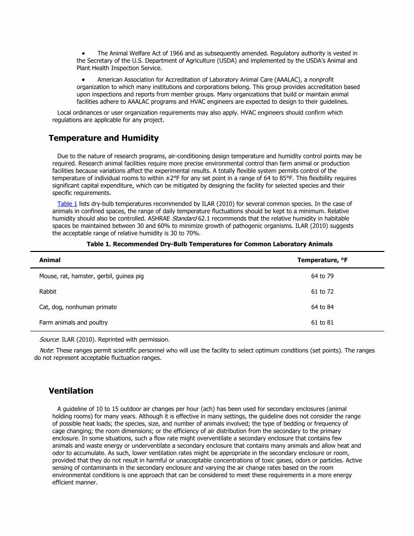
The Animal Welfare Act of 1966 and as subsequently amended. Regulatory authority is vested in the Secretary of the U.S. Department of Agriculture (USDA) and implemented by the USDA’s Animal and Plant Health Inspection Service.
American Association for Accreditation of Laboratory Animal Care (AAALAC), a nonprofit organization to which many institutions and corporations belong. This group provides accreditation based upon inspections and reports from member groups. Many organizations that build or maintain animal facilities adhere to AAALAC programs and HVAC engineers are expected to design to their guidelines.
Local ordinances or user organization requirements may also apply. HVAC engineers should confirm which regulations are applicable for any project.
Temperature and Humidity
Due to the nature of research programs, air-conditioning design temperature and humidity control points may be required. Research animal facilities require more precise environmental control than farm animal or production facilities because variations affect the experimental results. A totally flexible system permits control of the temperature of individual rooms to within ±2°F for any set point in a range of 64 to 85°F. This flexibility requires significant capital expenditure, which can be mitigated by designing the facility for selected species and their specific requirements.
Table 1 lists dry-bulb temperatures recommended by ILAR (2010) for several common species. In the case of animals in confined spaces, the range of daily temperature fluctuations should be kept to a minimum. Relative humidity should also be controlled. ASHRAE Standard 62.1 recommends that the relative humidity in habitable spaces be maintained between 30 and 60% to minimize growth of pathogenic organisms. ILAR (2010) suggests the acceptable range of relative humidity is 30 to 70%.
Table 1. Recommended Dry-Bulb Temperatures for Common Laboratory Animals
Animal Temperature, °F
Mouse, rat, hamster, gerbil, guinea pig 64 to 79
Rabbit 61 to 72
Cat, dog, nonhuman primate 64 to 84
Farm animals and poultry 61 to 81
Source: ILAR (2010). Reprinted with permission.
Note: These ranges permit scientific personnel who will use the facility to select optimum conditions (set points). The ranges do not represent acceptable fluctuation ranges.
Ventilation
A guideline of 10 to 15 outdoor air changes per hour (ach) has been used for secondary enclosures (animal holding rooms) for many years. Although it is effective in many settings, the guideline does not consider the range of possible heat loads; the species, size, and number of animals involved; the type of bedding or frequency of cage changing; the room dimensions; or the efficiency of air distribution from the secondary to the primary enclosure. In some situations, such a flow rate might overventilate a secondary enclosure that contains few animals and waste energy or underventilate a secondary enclosure that contains many animals and allow heat and odor to accumulate. As such, lower ventilation rates might be appropriate in the secondary enclosure or room, provided that they do not result in harmful or unacceptable concentrations of toxic gases, odors or particles. Active sensing of contaminants in the secondary enclosure and varying the air change rates based on the room environmental conditions is one approach that can be considered to meet these requirements in a more energy efficient manner.
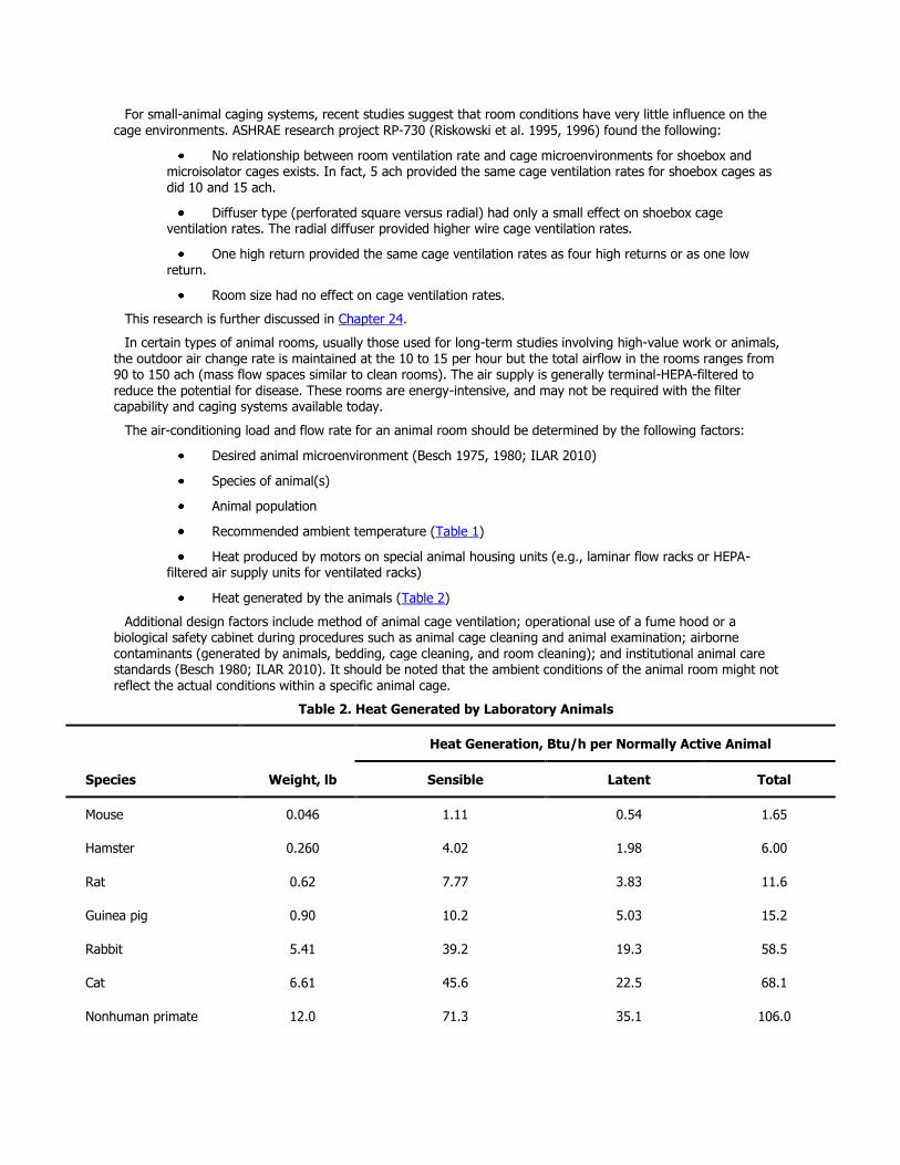
For small-animal caging systems, recent studies suggest that room conditions have very little influence on the
cage environments. ASHRAE research project RP-730 (Riskowski et al. 1995, 1996) found the following:
No relationship between room ventilation rate and cage microenvironments for shoebox and microisolator cages exists. In fact, 5 ach provided the same cage ventilation rates for shoebox cages as did 10 and 15 ach.
Diffuser type (perforated square versus radial) had only a small effect on shoebox cage ventilation rates. The radial diffuser provided higher wire cage ventilation rates.
One high return provided the same cage ventilation rates as four high returns or as one low return.
Room size had no effect on cage ventilation rates.
This research is further discussed in Chapter 24.
In certain types of animal rooms, usually those used for long-term studies involving high-value work or animals, the outdoor air change rate is maintained at the 10 to 15 per hour but the total airflow in the rooms ranges from 90 to 150 ach (mass flow spaces similar to clean rooms). The air supply is generally terminal-HEPA-filtered to
reduce the potential for disease. These rooms are energy-intensive, and may not be required with the filter capability and caging systems available today.
The air-conditioning load and flow rate for an animal room should be determined by the following factors:
Desired animal microenvironment (Besch 1975, 1980; ILAR 2010)
Species of animal(s)
Animal population
Recommended ambient temperature (Table 1)
Heat produced by motors on special animal housing units (e.g., laminar flow racks or HEPA-filtered air supply units for ventilated racks)
Heat generated by the animals (Table 2)
Additional design factors include method of animal cage ventilation; operational use of a fume hood or a biological safety cabinet during procedures such as animal cage cleaning and animal examination; airborne contaminants (generated by animals, bedding, cage cleaning, and room cleaning); and institutional animal care standards (Besch 1980; ILAR 2010). It should be noted that the ambient conditions of the animal room might not reflect the actual conditions within a specific animal cage.
Table 2. Heat Generated by Laboratory Animals
Species Weight, lb
Heat Generation, Btu/h per Normally Active Animal
Sensible Latent Total
Mouse 0.046 1.11 0.54 1.65
Hamster 0.260 4.02 1.98 6.00
Rat 0.62 7.77 3.83 11.6
Guinea pig 0.90 10.2 5.03 15.2
Rabbit 5.41 39.2 19.3 58.5
Cat 6.61 45.6 22.5 68.1
Nonhuman primate 12.0 71.3 35.1 106.0

Species Weight, lb
Heat Generation, Btu/h per Normally Active Animal
Sensible Latent Total
Dog 22.7 105.0 56.4 161.0
Dog 50.0 231.0 124.0 355.0
Animal Heat Production
Air-conditioning systems must remove the sensible and latent heat produced by laboratory animals. The literature concerning the metabolic heat production appears to be divergent, but new data are consistent. Current recommended values are given in Table 2. These values are based on experimental results and the following equation:
where
ATHG = average total heat gain, Btu/h per animal
M = metabolic rate of animal, Btu/h per animal = 6.6W 0.75
W = weight of animal, lb
Conditions in animal rooms must be maintained constant. This may require year-round availability of refrigeration and, in some cases, dual/standby chillers and emergency electrical power for motors and control instrumentation. Storage of critical spare parts is one alternative to installing a standby refrigeration system.
Design Considerations
If the entire animal facility or extensive portions of it are permanently planned for species with similar requirements, the range of individual adjustments may be reduced. Each animal room or group of rooms serving a common purpose should have separate temperature and humidity controls. The animal facility and human occupancy areas should be conditioned separately. The human areas may use a return air HVAC system and may be shut down on weekends for energy conservation. Separation prevents exposure of personnel to biological agents, allergens, and odors from animal rooms.
Control of air pressure in animal housing and service areas is important to ensure directional airflow. For example, quarantine, isolation, soiled equipment, and biohazard areas should be kept under negative pressure, whereas clean equipment and pathogen-free animal housing areas and research animal laboratories should be kept under positive pressure (ILAR 2010).
Supply air outlets should not cause drafts on research animals. Efficient air distribution for animal rooms is essential; this may be accomplished effectively by supplying air through ceiling outlets and exhausting air at floor level (Hessler and Moreland 1984). Supply and exhaust systems should be sized to minimize noise.
A study by Neil and Larsen (1982) showed that predesign evaluation of a full-size mock-up of the animal room and its HVAC system was a cost-effective way to select a system that distributes air to all areas of the animal-
holding room. Wier (1983) describes many typical design problems and their resolutions. Room air distribution should be evaluated using ASHRAE Standard 113 procedures to evaluate drafts and temperature gradients.
HVAC ductwork and utility penetrations must present a minimum number of cracks in animal rooms so that all wall and ceiling surfaces can be easily cleaned. Exposed ductwork is not generally recommended; however, if constructed of 316 stainless steel in a fashion to facilitate removal for cleaning, it can provide a cost-effective alternative. Joints around diffusers, grilles, and the like should be sealed. Exhaust air grilles with 1 in. washable or disposable filters are normally used to prevent animal hair and dander from entering the ductwork. Noise from the HVAC system and sound transmission from nearby spaces should be evaluated. Sound control methods such as separate air-handling systems or sound traps should be used as required.
Multiple-cubicle animal rooms enhance the operational flexibility of the animal room (i.e., housing multiple
species in the same room, quarantine, and isolation). Each cubicle should be treated as if it were a separate animal room, with air exchange/balance, temperature, and humidity control.
Caging Systems
Animal facilities use a number of different caging systems that can significantly affect the environment within the cage or the total heat load in the room. The purpose of the caging systems is to
Protect the health and wellbeing of the animals
Protect support staff from antigens released or shed by the animals
Minimize exposure of animals to pheromones released by other animals in the space
To provide the appropriate design, the HVAC engineer must be aware of the type of caging system to be used. Some common caging systems include the following:
Cage boxes made of sheet metal, plastic, or wire mesh, with the space inside the cage open to the room so the room’s macroenvironment is essentially identical to the cage’s microenvironment.
Cage boxes made primarily of plastic, with the top shielded from the room by a filter material to provide some level of isolation from the room. The filter is usually not sealed to the cage, so some open space between the room and the interior of the cage remains. Exchange of air, vapors, particulates, and gases between the room and the cage interior does occur, but the rate of exchange is reduced by the filter. The microenvironment of the interior of the cage is usually different from that of the room.
Plastic and wire cages that are part of a cage rack assembly, which provides varying degrees of isolation from the room. These usually provide filtered (generally HEPA-filtered) air directly to each individual or shelf of cage boxes. In some cases, both a fan-powered supply and an exhaust unit are used. In other cases, cage units are connected to the facility exhaust system to provide airflow. Facilities with this kind of caging system must be designed to accommodate the heat gain in the space if the exhaust is released in the room. Some heat gain may be excluded if the caging assembly is connected directly to the facility exhaust system. When the facility is used to provide the exhaust by direct connection to the caging assembly, the design must include provisions to control the airflow to ensure
that the overall proper airflow and relative static pressure of the room and each cage rack assembly is maintained, especially when caging and rack connections may be changed over time. The temperature and specific humidity within each cage will be higher than the ambient conditions of the room.
ANCILLARY SPACES FOR ANIMAL LABORATORIES
In addition to animal holding rooms, a facility intended to provide for an animal colony generally requires other areas, such as
Cage washer: Usually provided with some temperature control to minimize heat stress for occupants. In addition, specific exhaust hoods and separate exhaust ductwork should be considered for the space and equipment.
Feed storage: Usually provided with temperature and humidity control to protect quality and shelf life of feed.
Diagnostic laboratory: Usually provided with laboratory-quality air conditioning.
Treatment laboratory: Usually provided with laboratory-quality air conditioning.
Quarantine spaces: To separate incoming animals from the remainder of the colony until their health can be evaluated. These rooms are frequently located near the receiving location. Animal-room-quality air conditioning is provided.
Surgery suite: Sterile-quality air conditioning is provided. The suites frequently have provisions to exhaust anesthetic gases.
Necropsy laboratory: Usually provided with laboratory-quality air conditioning and frequently fitted with special exhaust tables or other means of protecting laboratory workers from exposure to chemical preservatives or biological contamination. For high-risk or high-hazard work, Type III biological safety cabinets may be provided.
Waste-holding room: Usually only provided with heating and ventilation, but maintained at negative pressure relative to adjacent areas. When used to store carcasses, a refrigerated storage unit of appropriate size should be provided.
CONTAINMENT LABORATORIES
With the initiation of biomedical research involving recombinant DNA technology, federal guidelines on laboratory safety were published that influence design teams, researchers, and others. Containment describes safe methods for managing hazardous chemicals and infectious agents in laboratories. The three elements of containment are laboratory operational practices and procedures, safety equipment, and facility design. Thus, the HVAC design engineer helps decide two of the three containment elements during the design phase.
In the United States, the U.S. Department of Health and Human Services (DHHS), Centers for Disease Control and Prevention (CDC), and National Institutes of Health (NIH) classify biological laboratories into four levels—Biosafety Levels 1 through 4—listed in DHHS (1999). The USDA Agricultural Research Service (ARS) Manual 242.1 (ARS 2002) similarly classifies biological laboratories, and also identifies a BSL 3Ag containment level.
Biosafety Level 1
Biosafety Level 1 is suitable for work involving well-characterized agents not known to consistently cause disease in healthy adult humans, and of minimal potential hazard to laboratory personnel and the environment. The laboratory is not necessarily separated from the general traffic patterns in the building. Work is generally conducted on open benchtops using standard microbiological practices. Special containment equipment is neither required nor generally used. The laboratory can be cleaned easily and contains a sink for washing hands. Federal guidelines for these laboratories contain no specific HVAC requirements.
Biosafety Level 2
Biosafety Level 2 is suitable for work involving agents of moderate potential hazard to personnel and the environment. Laboratory access is limited when certain work is in progress. The laboratory can be cleaned easily and contains a sink for washing hands. Biological safety cabinets (Class I or IIA2) are used whenever
Procedures with a high potential for creating infectious aerosols are conducted. These include centrifuging, grinding, blending, vigorous shaking or mixing, sonic disruption, opening containers of infectious materials, inoculating animals intranasally, and harvesting infected tissues or fluids from animals or eggs.
High concentrations or large volumes of infectious agents are used. Federal guidelines for these laboratories contain minimum facility standards.
At this level of biohazard, most research institutions have a full-time safety officer (or safety committee) who establishes facility standards. The federal guidelines for Biosafety Level 2 contain no specific HVAC requirements; however, typical HVAC design criteria can include the following:
100% outdoor air systems
6 to 15 air changes per hour
Directional airflow into the laboratory rooms
Site-specified hood face velocity at fume hoods (many institutions specify 80 to 100 fpm)
An assessment of research equipment heat load in a room.
Inclusion of biological safety cabinets
Most biomedical research laboratories are designed for Biosafety Level 2. However, the laboratory director must
evaluate the risks and determine the correct containment level before design begins.
Biosafety Level 3
Biosafety Level 3 applies to facilities in which work is done with indigenous or exotic agents that may cause serious or potentially lethal disease as a result of exposure by inhalation. The Biosafety Level 3 laboratory uses a physical barrier of two sets of self-closing doors to separate the laboratory work area from areas with unrestricted personnel access. This barrier enhances biological containment to within the laboratory work area.
The ventilation system must be single-pass, nonrecirculating and configured to maintain the laboratory at a negative pressure relative to surrounding areas. Audible alarms and visual monitoring devices are recommended to notify personnel if the laboratory pressure relationship changes from a negative to a positive condition. The user may wish to have alarms reported to a remote constantly monitored location. Gastight dampers are required in the supply and exhaust ductwork to allow decontamination of the laboratory. The ductwork between these dampers and the laboratory must also be gastight. All penetrations of the Biosafety Level 3 laboratory envelope must be sealable for containment and to facilitate gaseous decontamination of the work area.
All procedures involving the manipulation of infectious materials are conducted inside biological safety cabinets. The engineer must ensure that the connection of the cabinets to the exhaust system does not adversely affect the performance of the biological safety cabinets or the exhaust system. Refer to the section on Biological Safety Cabinets for further discussion.
The exhaust air from biological safety cabinets and/or the laboratory work area may require HEPA filtration. The need for filtration should be reviewed with the appropriate safety officers. If required, HEPA filters should be equipped with provisions for bag-in, bag-out filter handling systems and gastight isolation dampers for biological decontamination of the filters.
The engineer should review with the safety officer the need for special exhaust or filtration of exhaust from any scientific equipment located in the Biosafety Level 3 laboratory.
Biosafety Level 4
Biosafety Level 4 is required for work with dangerous and exotic agents that pose a high risk of aerosol-transmitted laboratory infections and life-threatening disease. HVAC systems for these areas will have stringent design requirements that must be determined by the biological safety officer.
Biosafety Level 3Ag
Biosafety Level 3Ag is requires for work with certain biological agents in large animal species. Using the containment features of the standard BSL 3 facility as a starting point, BSL 3Ag facilities are specifically designed to protect the environment by including almost all of the features ordinarily used for BSL 4 facilities as enhancements. All BSL 3Ag containment spaces must be designed, constructed, and certified as primary containment barriers.
SCALE-UP LABORATORIES
Scale-up laboratories are defined differently depending on the nature and volume of work being conducted. For laboratories performing recombinant DNA research, large-scale experiments involve 10 L or more. Generally, the holding vessels do not exceed 100 L. A chemical or biological laboratory is defined as scale-up when the principal holding vessels are glass or ceramic. When the vessels are constructed primarily of metals, the laboratory is considered a pilot plant, which this chapter does not address. The amount of experimental materials present in scale-up laboratories is generally significantly greater than the amount found in the small-scale laboratory. Experimental equipment is also larger and therefore requires more space; these may include larger chemical fume hoods or reaction cubicles that may be of the walk-in type. Significantly higher laboratory airflow rates are needed to maintain the face velocity of the chemical fume hoods or reaction cubicles, although their size frequently presents problems of airflow uniformity over the entire face area. Walk-in hoods are sometimes entered during an
experimental run, so provisions for breathing-quality air stations and other forms of personnel protection should be
considered. Environmental containment or the ability to decontaminate the laboratory, the laboratory exhaust airstream, or other effluent may be needed in the event of an upset. Scale-up laboratories may be in operation for sustained periods.
For large walk-in hoods or reaction cubicles, the large volume of exhaust air required and the simultaneous requirement for supply air can result in temperature gradient problems in the space. Local specific ventilation capability is frequently provided within the laboratory space but outside the fume hood or reaction cubicle.
Large hoods, similar to what sometimes were called “California hoods,” may also be provided in scale-up laboratories. These hoods are large in volume and height, provide access on multiple sides, and can be customized using standard components. Before beginning any custom hood design, the HVAC engineer, working with the user, should first determine how the hood will be used. Then the HVAC engineer can develop a custom hood design that considers
What access is required for setup of experimental apparatus
How the hood is expected to function during experimental runs
Which doors or sashes should be open during a run
Safety and ergonomic issues
What features should be incorporated
Airflow required to achieve satisfactory containment
Testing and balancing criteria should also be defined early in the design process. Mockups and factory testing of prototypes should be considered to avoid problems with installed hoods.
TEACHING LABORATORIES
Laboratories in academic settings can generally be classified as either those used for instruction or those used for research. Research laboratories vary significantly depending on the work being performed; they generally fit into one of the categories of laboratories described previously.
The design requirements for teaching laboratories also vary based on their function. The designer should become familiar with the specific teaching program, so that a suitable hazard assessment can be made. For example, the requirements for the number and size of fume hoods vary greatly between undergraduate inorganic and graduate organic chemistry teaching laboratories. Unique aspects of teaching laboratories include the need of the instructor to be in visual contact with the students at their work stations and to have ready access to the controls for the fume hood operations and any safety shutoff devices and alarms. Frequently, students have not received extensive safety instruction, so easily understood controls and labeling are necessary. Because the teaching environment depends on verbal communication, sound from the building ventilation system is an important concern.
CLINICAL LABORATORIES
Clinical laboratories are found in hospitals and as stand-alone operations. Work in these laboratories generally consists of handling human specimens (blood, urine, etc.) and using chemical reagents for analysis. Some samples may be infectious; because it is impossible to know which samples may be contaminated, good work practices
require that all be handled as biohazardous materials. The primary protection of the staff at clinical laboratories depends on the techniques and laboratory equipment (e.g., biological safety cabinets) used to control aerosols, spills, or other inadvertent releases of samples and reagents. People outside the laboratory must also be protected.
The building HVAC system can provide additional protection with suitable exhaust, ventilation, and filtration. The HVAC engineer is responsible for providing an HVAC system that meets the biological and chemical safety requirements. The engineer should consult with appropriate senior staff and safety professionals to ascertain what potentially hazardous chemical or biohazardous conditions will be in the facility and then provide suitable engineering controls to minimize risks to staff and the community. Appropriate laboratory staff and the design
engineer should consider using biological safety cabinets, chemical fume hoods, and other specific exhaust
systems.
RADIOCHEMISTRY LABORATORIES
In the United States, laboratories located in Department of Energy (DOE) facilities are governed by DOE regulations. All other laboratories using radioactive materials are governed by the Nuclear Regulatory Commission (NRC), state, and local regulations. Other agencies may be responsible for the regulation of other toxic and carcinogenic materials present in the facility. Laboratory containment equipment for nuclear processing facilities are treated as primary, secondary, or tertiary containment zones, depending on the level of radioactivity anticipated for the area and the materials to be handled.Chapter 28 has additional information on nuclear laboratories.
OPERATION AND MAINTENANCE
During long-term research studies, laboratories may need to maintain design performance conditions with no interruptions for long periods. Even when research needs are not so demanding, systems that maintain air balance, temperature, and humidity in laboratories must be highly reliable, with a minimal amount of downtime. The designer should work with operation and maintenance personnel as well as users early in the design of systems to gain their input and agreement.
System components must be of adequate quality to achieve reliable HVAC operation, and they should be reasonably accessible for maintenance. Laboratory work surfaces should be protected from possible leakage of coils, pipes, and humidifiers. Changeout of supply and exhaust filters should require minimum downtime.
Centralized monitoring of laboratory variables (e.g., pressure differentials, face velocity of fume hoods, supply flows, and exhaust flows) is useful for predictive maintenance of equipment and for ensuring safe conditions. For their safety, laboratory users should be instructed in the proper use of laboratory fume hoods, safety cabinets, ventilated enclosures, and local ventilation devices. They should be trained to understand the operation of the devices and the indicators and alarms that show whether they are safe to operate. Users should request periodic testing of the devices to ensure that they and the connected ventilation systems are operating properly.
Personnel who know the nature of the contaminants in a particular laboratory should be responsible for decontamination of equipment and ductwork before they are turned over to maintenance personnel for work.
Maintenance personnel should be trained to keep laboratory systems in good operating order and should understand the critical safety requirements of those systems. Preventive maintenance of equipment and periodic checks of air balance should be scheduled. High-maintenance items should be placed outside the actual laboratory (in service corridors or interstitial space) to reduce disruption of laboratory operations and exposure of the maintenance staff to laboratory hazards. Maintenance personnel must be aware of and trained in procedures for maintaining good indoor air quality (IAQ) in laboratories. Many IAQ problems have been traced to poor maintenance due to poor accessibility (Woods et al. 1987).
ENERGY
Because of the nature of the functions they support, laboratory HVAC systems consume large amounts of energy (high flow rates; high static pressure filtration; critical cooling, heating, and humidification). Efforts to reduce energy use must not compromise standards established by safety officers. Typically, HVAC systems supporting
laboratories and animal areas use 100% outdoor air and operate continuously. All HVAC systems serving laboratories can benefit from energy reduction techniques that are either an integral part of the original design or added later. Energy reduction techniques should be analyzed in terms of both appropriateness to the facility and economic payback.
Energy-efficient design is an iterative process that begins with establishing communication among all members of the design team. Each design discipline has an effect on the energy load. On a macro scale, building orientation, window shading devices, and high-performance envelopes offer opportunity for energy use reduction. On a micro scale, for example, the choice of a lighting system can affect sensible heat gain. Energy-efficient designs should recognize the variability of exhaust, envelope, and equipment loads and use systems that respond appropriately and perform efficiently during partial-load conditions.
The HVAC engineer must understand and respond to the scientific requirements of the facility. Research
requirements typically include continuous control of temperature, humidity, relative static pressure, and air quality. Energy reduction systems must maintain required environmental conditions during both occupied and unoccupied modes.
Energy Efficiency
Energy can be used more efficiently in laboratories by reducing exhaust air requirements. One way to achieve this is to use variable-volume control of exhaust air through the fume hoods to reduce exhaust airflow when the fume hood sash is not fully open. Recent changes in NFPA Standard 45 and ANSI/AIHA Standard Z9.5 allow the use of a much lower fume hood minimum flow rate with variable-volume hoods (as low as about 100 cfm for a traditional 6 ft) hood when the sash is closed), depending on the system design and aspects of laboratory operations. Any airflow control must be integrated with the laboratory control system, described in the section on Control, and its setting and operation must not jeopardize the safety and function of the laboratory.
Reducing ventilation requirements in laboratories and vivariums based on real-time sensing of contaminants in the room environment offers opportunities for energy conservation. This approach can potentially safely reduce
lab air change rates to as low as 2 ach when the lab air is “clean” and the fume hood exhaust or room cooling load requirements do not require higher airflow rates. Research by Sharp (2010) showed that lab rooms are on average “clean” of contaminants in excess of about 98% of the time.
Setback controls that reduce ventilation rates when the laboratory is unoccupied can also reduce energy consumption. Timing devices, sensors, manual override, or a combination of these can be used to set back the controls at night. There should be no entry into the laboratory during unoccupied setback times and occupied ventilation rates should be engaged possibly 1 h or more in advance of occupancy to properly dilute any contaminants. If this strategy is used, the safety and function of the laboratory must be considered, and appropriate safety officers should be consulted.
Fume hood selection also impacts exhaust airflow requirements and energy consumption. Modern fume hood designs use several techniques to reduce airflow requirements, including reduced face opening sashes and specially designed components that allow operation with reduced inflow velocities. When considering these features, it is important to obtain approval of laboratory occupants and safety personnel.
Laboratory exhaust systems typically use constant-speed fans to discharge exhaust air at a constant velocity to prevent cross contamination with supply air intakes. Alternative approaches to reduce the considerable energy consumption of exhaust fans include using taller stacks, and real-time reduction of exhaust exit velocity based on sensing either wind direction and velocity or reduced contaminant levels in the exhaust fan plenum.
Room-cooling approaches, such as hydronic cooling using local fan-coil units or noncondensing, chilled radiant ceiling panels, passive chilled beams, or active chilled beams offer opportunities for energy conservation. These approaches decouple the room cooling function from the ventilation air requirements, potentially reducing outdoor air needs, overall HVAC capacity, and reheat energy. Less energy is needed to pump chilled water than to provide the equivalent amount of airflow required for a given level of cooling. Note that some form of dew-point sensing and possibly condensation monitoring is recommended (Rumsey et al. 2007) for noncondensing hydronic cooling approaches.
Energy Recovery
Energy can often be recovered economically from the exhaust airstream in laboratory buildings with large quantities of exhaust air. Many energy recovery systems are available, including rotary air-to-air energy exchangers or heat wheels, coil energy recovery loops (runaround cycle), twin tower enthalpy recovery loops, heat pipe heat exchangers, fixed-plate heat exchangers, thermosiphon heat exchangers, and direct evaporative cooling. Some of these technologies can be combined with indirect evaporative cooling for further energy recovery. See Chapters 25 and 45 of the 2008 ASHRAE Handbook—HVAC Systems and Equipment for more information.
Concerns about the use of energy recovery devices in laboratory HVAC systems include (1) the potential for cross-contamination of chemical and biological materials from exhaust air to the intake airstream, and (2) the potential for corrosion and fouling of devices located in the exhaust airstream.
Energy recovery is also possible for hydronic systems associated with HVAC. Rejected heat from centrifugal
chillers can be used to produce low-temperature reheat water. Potential also exists in plumbing systems, where waste heat from washing operations can be recovered to heat makeup water.
Sustainable Design
Laboratories present unique challenges and opportunities for energy efficiency and sustainable design. Laboratory systems are complex, use significant energy, have health and life safety implications, need long-term flexibility and adaptablity, and handle potentially hazardous effluent with associated environmental impacts. Therefore, before implementing energy-efficiency and sustainable-design protocols, the engineer must be aware of the effects of these measures on the laboratory processes, which affect the safety of the staff, environment, and scientific procedures.
Several laboratory facilities have achieved high recognition for energy efficiency and sustainable design. Sustainable-design features specific to laboratory facilities include all aspects of design, construction, and operations. These features include (1) managing air and water effluent on the site; (2) reducing water used by laboratory processes; (3) rightsizing equipment and improving its energy efficiency; (4) hazardous material
handling; (5) ventilation system enhancements, including modeling airflow patterns, fume hood testing, and additional safety alarming; and (6) laboratory-specific opportunities for innovation.
COMMISSIONING
In addition to HVAC systems, electrical systems and chemical handling and storage areas should be commissioned. Training of technicians, scientists, and maintenance personnel is a critical aspect of the commissioning process. Users should understand the systems and their operation.
It should be determined early in the design process whether any laboratory systems must comply with Food and Drug Administration (FDA) regulations because these systems have additional design, commissioning, and potential validation requirements. Commissioning is defined in Chapter 43, and the process is outlined in ASHRAE Guidelines 0 and 1.1. Laboratory commissioning can be more demanding than that described in ASHRAE Guidelines and includes systems that are not associated with other occupancies. Requirements for commissioning should be clearly understood by all participants, including the contractors and the owner’s personnel. Roles and responsibilities should be defined, and responsibilities for documenting results should be established.
Laboratory commissioning starts with the intended use of the laboratory and should include development of a commissioning plan, as outlined in the ASHRAE guidelines. The start-up and prefunctional testing of individual components should come first; after individual components are successfully tested, the entire system should be functionally tested. This requires verification and documentation that the design meets applicable codes and standards and that it has been constructed in accordance with the design intent and owner’s project requirements. Many facilities require integrated systems testing to verify the HVAC system is properly coordinated with other systems, such as fire alarm or emergency power systems. Before general commissioning begins, obtain the following data:
Complete set of the laboratory utility drawings
Definition of the use of the laboratory and an understanding of the work being performed
Equipment requirements
All test results
Basis of design (BOD) that includes the intent of system operation
Owner’s project requirements (OPR)
For HVAC and associated integrated system commissioning, the following should be verified and documented:
Manufacturer’s requirements for airflow for biological safety cabinets and laminar flow clean benches have been met.
Exhaust system configuration, damper locations, and performance characteristics, including any required emission equipment, are correct.

Approved test and balance report.
Control system operates as specified. Controls include fume hood alarm; miscellaneous safety alarm systems; fume hood and other exhaust airflow regulation; laboratory pressurization control system; laboratory temperature control system; and main ventilation unit controls for supply, exhaust, and heat recovery systems. Control system performance verification should include speed of response, accuracy, repeatability, turndown, and stability.
Desired laboratory pressurization relationships are maintained throughout the laboratory, including entrances, adjoining areas, air locks, interior rooms, and hallways. Balancing terminal devices within 10% of design requirements will not provide adequate results. Additionally, internal pressure relationships can be affected by airflow around the building. See Chapter 24 of the 2009 ASHRAE Handbook—Fundamentals for more information.
Fume hood containment performance is within specification. ASHRAE Standard 110 provides criteria for this evaluation.
Dynamic response of the laboratory’s control system is satisfactory. One method of testing the control system is to open and shut laboratory doors during fume hood performance testing.
System fault tree and failure modes are as specified, including life safety fan system shutdown impact on proper provisions for egress from the building within allowable limits of door-opening force requirements
Standby electrical power systems function properly.
Design noise criterion (NC) levels of occupied spaces have been met.
Training of facilities staff and laboratory occupants should also be considered part of the commissioning and design process. Training should address both the operation of individual system components and the overall system.
ECONOMICS
In laboratories, HVAC systems make up a significant part (often 30 to 50%) of the overall construction budget.
The design criteria and system requirements must be reconciled with the budget allotment for HVAC early in the planning stages and continually throughout the design stages to ensure that the project remains within budget.
Every project must be evaluated on both its technical features and its economics. The following common economic terms are discussed in Chapter 37 and defined here as follows:
Initial cost: Costs to design, install, and test an HVAC system such that it is fully operational and suitable for use.
Operating cost: Cost to operate a system (including energy, maintenance, and component replacements) such that the total system can reach the end of its normal useful life.
Life-cycle cost: Cost related to the total cost over the life of the HVAC system, including initial capital cost, considering the time value of money.
Mechanical and electrical costs related to HVAC systems are commonly assigned a depreciation life based on current tax policies. This depreciation life may be different from the projected functional life of the equipment, which is influenced by the quality of the system components and of the maintenance they receive. Some portions of the system, such as ductwork, could last the full life of the building. Other components, such as air-handling
units, may have a useful life of 15 to 30 years, depending on their original quality and ongoing maintenance efforts. Estimated service life of equipment is listed in Chapter 37.
Engineering economics can be used to evaluate life-cycle costs of configuration (utility corridor versus interstitial space), systems, and major equipment. The user or owner makes a business decision concerning the quality and reliability of the system and its ongoing operating costs. The HVAC engineer may be asked to provide an objective analysis of energy, maintenance, and construction costs, so that an appropriate life-cycle cost analysis can be made. Other considerations that may be appropriate include economic influences related to the long-term use of energy and governmental laws and regulations.
Many technical considerations and the great variety of equipment available influence the design of HVAC
systems. Factors affecting design must be well understood to ensure appropriate comparisons between various systems and to determine the impact on either first or operating costs.
REFERENCES
AGS. 2007. Guidelines for gloveboxes, 3rd ed. American Glovebox Society, Santa Rosa, CA.
AIHA. 2003. Laboratory ventilation. ANSI/AIHA Standard Z9.5-03. American Industrial Hygiene Association, Fairfax, VA.
Alereza, T. and J. Breen, III. 1984. Estimates of recommended heat gains due to commercial appliances and equipment.ASHRAE Transactions 90(2A):25-58.
ARS. 2002. Facilities design standards manual. U.S. Department of Agriculture, Agricultural Research Service, Washington, D.C.
ASHRAE. 2010.Ventilation for acceptable indoor air quality. ANSI/ ASHRAE Standard 62.1-2010.
ASHRAE. 2009. Method of testing for room air diffusion. ANSI/ASHRAE Standard 113-2009.
ASHRAE. 2007. Method of testing general ventilation air cleaning devices for removal efficiency by particle size. ANSI/ASHRAE Standard 52.2-2007.
ASHRAE. 1995. Method of testing performance of laboratory fume hoods. ANSI/ASHRAE Standard 110-1995.
ASHRAE. 2008. HVAC&R technical requirements for the commissioning process. Guideline 1.1-2008.
Besch, E. 1975. Animal cage room dry bulb and dew point temperature differentials. ASHRAE Transactions 81(2):459-458.
Besch, E. 1980. Environmental quality within animal facilities. Laboratory Animal Science 30(2II):385-406.
Caplan, K. and G. Knutson. 1977. The effect of room air challenge on the efficiency of laboratory fume hoods. ASHRAE Transactions 83(1): 141-156.
Caplan, K. and G. Knutson. 1978. Laboratory fume hoods: Influence of room air supply. ASHRAE Transactions 84(1):511-537.
Code of Federal Regulations. (Latest edition). Good laboratory practices. CFR 21 Part 58. U.S. Government Printing Office, Washington, D.C.
DHHS. 1999. Biosafety in microbiological and biomedical laboratories, 4th ed. Publication No. (CDC) 93-8395. U.S. Department of Health and Human Services, NIH, Bethesda, MD.
Dorgan, C.B., C.E. Dorgan, and I.B.D. McIntosh. 2002. ASHRAE laboratory design guide. ASHRAE.
Eagleston, J., Jr. 1984. Aerosol contamination at work. In The international hospital federation yearbook. Sabrecrown Publishing, London.
Halitsky, J. 1988. Dispersion of laboratory exhaust gas by large jets. 81st Annual Meeting of the Air Pollution Control Association, June, Dallas.
Halitsky, J. 1989. A jet plume model for short stacks. APCA Journal 39(6).
Hessler, J. and A. Moreland. 1984. Design and management of animal facilities. In Laboratory animal medicine, J. Fox, B. Cohen, F. Loew, eds. Academic Press, San Diego, CA.
ICC. 2009. International building code®. International Code Council, Washington, D.C.
ILAR. 2010. Guide for the care and use of laboratory animals, 8th ed. Institute of Laboratory Animal Resources, National Academy of Sciences, the National Academies Press, Washington, D.C.
Klein, R., C. King, and A. Kosior. 2009. Laboratory air quality and room ventilation rates. Journal of Chemical Health and Safety (9/10).
Marsh, C.W. 1988. DDC systems for pressurization, fume hood face velocity and temperature control in variable air volume laboratories. ASHRAE Transactions 94(2):1947-1968.

Murakami, S., A. Mochida, R. Ooka, S. Kato, and S. Iizuka. 1996. Numerical prediction of flow around buildings
with various turbulence models: Comparison of k-ε, EVM, ASM, DSM, and LES with wind tunnel tests. ASHRAE Transactions 102(1):741-753.
Neil, D. and R. Larsen. 1982. How to develop cost-effective animal room ventilation: Build a mock-up. Laboratory Animal Science (Jan-Feb): 32-37.
NFPA. 1994. Guide for venting of deflagrations. ANSI/NFPA Standard 68-94.
NFPA. 1996. Flammable and combustible liquids code. ANSI/NFPA Standard 30-96.
NFPA. 1998. Storage, use, and handling of compressed and liquefied gases in portable cylinders. NFPA Standard 55-98.
NFPA. 1999. Health care facilities. ANSI/NFPA Standard 99-99.
NFPA. 2000. Fire protection for laboratories using chemicals. ANSI/NFPA Standard 45-2000
NIH. 1999a. Research laboratory design policy and guidelines. Office of Research Services, National Institutes of Health, Bethesda, MD.
NIH. 1999b. Vivarium design policy and guidelines. Office of Research Services, National Institutes of Health, Bethesda, MD.
NSF. 1992. Class II (laminar flow) biohazard cabinetry. Standard 49-92. NSF International, Ann Arbor, MI.
Petersen, R.L., J. Carter, and M. Ratcliff. 1997. The influence of architectural screens on exhaust dilution. ASHRAEResearch Project RP-805. Draft Report approved by Technical Committee June 1997.
Rake, B. 1978. Influence of crossdrafts on the performance of a biological safety cabinet. Applied and Environmental Microbiology (August): 278-283.
Riskowski, et al. 1995. Development of ventilation rates and design information for laboratory animal facilities—Part I. ASHRAE Research Project RP-730. ASHRAE Transactions 101(2).
Riskowski, et al. 1996. Development of ventilation rates and design information for laboratory animal facilities—Part II. ASHRAE Research Project RP-730. ASHRAE Transactions 102(2).
Rumsey, P. and J. Weale. 2007. Chilled beams in labs: Eliminating reheat and saving energy on a budget. ASHRAE Journal49(1):18-25.
Schuyler, G. 2009. The effect of air change rate on recovery from a spill. In Seminar 26, presented at 2009 ASHRAE Winter Conference, Chicago.
Sharp, G.P. 2010. Demand-based control of lab air change rates. ASHRAE Journal 52(2):30-41.
SEFA. Laboratory fume hoods recommended practices. SEFA 1. Scientific Equipment and Furniture Association, Hilton Head, SC.
Stuart, D., M. First, R. Rones, and J. Eagleston. 1983. Comparison of chemical vapor handling by three types of Class II biological safety cabinets. Particulate & Microbial Control (March/April).
West, D.L. 1978. Assessment of risk in the research laboratory: A basis for facility design. ASHRAE Transactions 84(1):547-557.
Wier, R.C. 1983. Toxicology and animal facilities for research and development. ASHRAE Transactions 89(2B):533-541.
Wilson, D.J., et al. 1998. Adjacent building effects on laboratory fume hood stack design. ASHRAE Research Project RP-897, Final Report.
Woods, J. 1980. The animal enclosure—A microenvironment. Laboratory Animal Science 30(2II):407-413.
Woods, J., J. Janssen, P. Morey, and D. Rask. 1987. Resolution of the “sick” building syndrome. Proceedings of ASHRAE Conference: Practical Control of Indoor Air Problems, pp. 338-348.
Zhou, Y. and T. Stathopoulos. 1996. Application of two-layer methods for the evaluation of wind effects on a cubic building. ASHRAE Transactions 102(1):754-764.
BIBLIOGRAPHY
Abramson, B. and T. Tucker. 1988. Recapturing lost energy. ASHRAE Journal 30(6):50-52.
Adams, J.B., Jr. 1989. Safety in the chemical laboratory: Synthesis—Laboratory fume hoods. Journal of Chemical Education66(12).
Ahmed, O. and S.A Bradley. 1990. An approach to determining the required response time for a VAV fume hood control system. ASHRAE Transactions 96(2):337-342.
Ahmed, O., J.W. Mitchell, and S.A. Klein. 1993. Dynamics of laboratory pressurization. ASHRAE Transactions 99(2):223-229.
Albern, W., F. Darling, and L. Farmer. 1988. Laboratory fume hood operation. ASHRAE Journal 30(3):26-30.
Anderson, S. 1987. Control techniques for zoned pressurization. ASHRAE Transactions 93(2B):1123-1139.
Anderson, C.P. and K.M. Cunningham. 1988. HVAC controls in laboratories—A systems approach. ASHRAE Transactions94(1):1514-1520.
Barker, K.A., O. Ahmed, and J.A. Parker. 1993. A methodology to determine laboratory energy consumption and conservation characteristics using an integrated building automation system. ASHRAE Transactions 99(2):1155-1167.
Baylie, C.L. and S.H. Schultz. 1994. Manage change: Planning for the validation of HVAC Systems for a clinical trials production facility. ASHRAE Transactions 100(1):1660-1668.
Bell, G.C., E. Mills, G. Sator, D. Avery, M. Siminovitch, and M.A. Piette. 1996. A design guide for energy-efficient research laboratories. LBNL-PUB-777. Lawrence Berkeley National Laboratory, Berkeley, CA.
Bertoni, M. 1987. Risk management considerations in design of laboratory exhaust stacks. ASHRAE Transactions93(2B):2149-2164.
Bossert, K.A. and S.M. McGinley. 1994. Design characteristics of clinical supply laboratories relating to HVAC systems.ASHRAE Transactions 94(100):1655-1659.
Brow, K. 1989. AIDS research laboratories—HVAC criteria. In Building Systems: Room Air and Air Contaminant Distribution, L.L. Christianson, ed. ASHRAE cosponsored Symposium, pp. 223-225.
Brown, W.K. 1993. An integrated approach to laboratory energy efficiency. ASHRAE Transactions 99(2):1143-1154.
Carnes, L. 1984. Air-to-air heat recovery systems for research laboratories. ASHRAE Transactions 90(2A):327.
Coogan, J.J. 1994. Experience with commissioning VAV laboratories. ASHRAE Transactions 100(1):1635-1640.
Crane, J. 1994. Biological laboratory ventilation and architectural and mechanical implications of biological safety cabinet selection, location, and venting. ASHRAE Transactions 100(1):1257-65.
CRC. 2000. CRC handbook of laboratory safety, 5th ed. CRC Press, Boca Raton, FL.
Dahan, F. 1986. HVAC systems for chemical and biochemical laboratories. Heating, Piping and Air Conditioning (May):125-130.
Davis, S. and R. Benjamin. 1987. VAV with fume hood exhaust systems. Heating, Piping and Air Conditioning (August):75-78.
Degenhardt, R. and J. Pfost. 1983. Fume hood system design and application for medical facilities. ASHRAE Transactions89(2B):558-570.
DHHS. 1981. NIH guidelines for the laboratory use of chemical carcinogens. Department of Health and Human Services, National Institutes of Health, Bethesda, MD.
DiBeradinis, L., J. Baum, M. First, G. Gatwood, E. Groden, and A. Seth. 1992. Guidelines for laboratory design: Health and safety considerations. John Wiley & Sons, Boston.
Doyle, D.L., R.D. Benzuly, and J.M. O’Brien. 1993. Variable volume retrofit of an industrial research laboratory. ASHRAE Transactions 99(2): 1168-1180.
Flanherty, R.J. and R. Gracilieri. 1994. Documentation required for the validation of HVAC systems. ASHRAE Transactions100(1):1629-1634.
Ghidoni, D.A. and R.L. Jones, Jr. 1994. Methods of exhausting a BSC to an exhaust system containing a VAV component.ASHRAE Transactions 100(1):1275-1281.
Hayter, R.B. and R.L. Gorton. 1988. Radiant cooling in laboratory animal caging. ASHRAE Transactions 94(1):1834-1847.
Hitchings, D.T. and R.S. Shull 1993. Measuring and calculating laboratory exhaust diversity—Three case studies. ASHRAE Transactions 99(2): 1059-1071.
ILAR. 1996. Laboratory animal management—Rodents. ILAR News 20(3).
Kirkpatrick, A., et al. A mathematical model for the prediction of laboratory fume hood airflow: ASHRAE Research ProjectRP-848, Final Report.
Knutson, G. 1984. Effect of slot position on laboratory fume hood performance. Heating, Piping and Air Conditioning(February):93-96.
Knutson, G. 1987. Testing containment laboratory hoods: A field study. ASHRAE Transactions 93(2B):1801-1812.
Koenigsberg, J. and H. Schaal. 1987. Upgrading existing fume hood installations. Heating, Piping and Air Conditioning(October):77-82.
Koenigsberg, J. and E. Seipp. 1988. Laboratory fume hood—An analysis of this special exhaust system in the post “Knutson-Caplan” era. ASHRAE Journal 30(2):43-46.
Laboratory & Health Facilities Programming & Planning. Planning Monograph 1.0. Planning Collaborative Ltd., Reston, VA.
Lacey, D.R. 1994. HVAC for a low temperature biohazard facility. ASHRAE Transactions 100(1):1282-1286.
Lentz, M.S. and A.K. Seth. 1989. A procedure for modeling diversity in laboratory VAV systems. ASHRAE Transactions95(1):114-120.
Maghirang, R.G., G.L. Riskowski, P.C. Harrison, H.W. Gonyou, L. Sebek, and J. McKee. 1994. An individually ventilated caging system for laboratory rats. ASHRAE Transactions 100(1):913-920.
Maust, J. and R. Rundquist. 1987. Laboratory fume hood systems—Their use and energy conservation. ASHRAE Transactions 93(2B):1813-1821.
McDiarmid, M.D. 1988. A quantitative evaluation of air distribution in full scale mock-ups of animal holding rooms. ASHRAE Transactions 94(1B): 685-693.
Mikell, W. and F. Fuller. 1988. Safety in the chemical laboratory: Good hood practices for safe hood operation. Journal of Chemical Education 65(2).
Moyer, R.C. 1983. Fume hood diversity for reduced energy consumption. ASHRAE Transactions 89(2B):552-557.
Moyer, R. and J. Dungan. 1987. Turning fume hood diversity into energy savings. ASHRAE Transactions 93(2B):1822-1834.
Murray, W., A. Streifel, T. O’Dea, and F. Rhame. 1988. Ventilation for protection of immune compromised patients.ASHRAE Transactions 94(1): 1185-1192.
NFPA. 1994. Gaseous hydrogen systems at consumer sites. ANSI/NFPA Standard 50A. National Fire Protection Association, Quincy, MA.
NFPA. 1996. Water spray fixed systems for fire protection. ANSI/NFPA Standard 15.
NFPA. 1996. Installation of air conditioning and ventilating systems. ANSI/NFPA Standard 90A.
NFPA. 1996. National electrical code. ANSI/NFPA Standard 70.
NFPA. 1998. Liquefied petroleum gas code. NFPA Standard 58.
NIH. 1996. Clinical center design policy and guidelines. Office of Research Services, National Institutes of Health, Bethesda, MD.
NIH. 1996. Reference material for the design policy and guidelines. Office of Research Services, National Institutes of Health, Bethesda, MD.
Neuman, V. 1989. Design considerations for laboratory HVAC system dynamics. ASHRAE Transactions 95(1):121-124.
Neuman, V. 1989. Disadvantages of auxiliary air fume hoods. ASHRAE Transactions 95(1):70-75.
Neuman, V. 1989. Health and safety in laboratory plumbing. Plumbing Engineering (March):21-24.
Neuman, V. and H. Guven. 1988. Laboratory building HVAC systems optimization. ASHRAE Transactions 94(2):432-451.
Neuman, V. and W. Rousseau. 1986. VAV for laboratory hoods—Design and costs. ASHRAE Transactions 92(1A):330-346.
Neuman, V., F. Sajed, and H. Guven. 1988. A comparison of cooling thermal storage and gas air conditioning for a lab building. ASHRAE Transactions 94(2):452-468.
Parker, J.A., O. Ahmed, and K.A. Barker. 1993. Application of building automation system (BAS) in evaluating diversity and other characteristics of a VAV laboratory. ASHRAE Transactions 99(2):1081-1089.
Peterson, R. 1987. Designing building exhausts to achieve acceptable concentrations of toxic effluents. ASHRAE Transactions 93(2):2165-2185.
Peterson, R.L., E.L. Schofer, and D.W. Martin. 1983. Laboratory air systems—Further testing. ASHRAE Transactions89(2B):571-596.
Pike, R. 1976. Laboratory-associated infections: Summary and analysis of 3921 cases. Health Laboratory Science13(2):105-114.
Rabiah, T.M. and J.W. Wellenbach. 1993. Determining fume hood diversity factors. ASHRAE Transactions 99(2):1090-1096.
Rhodes, W.W. 1988. Control of microbioaerosol contamination in critical areas in the hospital environment. ASHRAE Transactions 94(1):1171-1182.
Richardson, G. 1994. Commissioning of VAV laboratories and the problems encountered. ASHRAE Transactions100(1):1641-1645.
Rizzo, S. 1994. Commissioning of laboratories: A case study. ASHRAE Transactions 100(1):1646-1652.
Sandru, E. 1996. Evaluation of the laboratory equipment component of cooling loads. ASHRAE Transactions 102(1):732-737.
Schuyler, G. and W. Waechter. 1987. Performance of fume hoods in simulated laboratory conditions. Report No. 487-1605 by Rowan Williams Davies & Irwin, Inc., under contract for Health and Welfare Canada.
Schwartz, Leonard. 1994. Heating, ventilating and air conditioning considerations for pharmaceutical companies.Pharmaceutical Engineering 14(4).
Sessler, S. and R. Hoover. 1983. Laboratory fume hood noise. Heating, Piping, and Air Conditioning (September):124-137.
Simons, C.G. 1991. Specifying the correct biological safety cabinet. ASH-RAE Journal 33(8).
Simons, C.G. and R. Davoodpour. 1994. Design considerations for laboratory facilities using molecular biology techniques.ASHRAE Trans-actions 100(1):1266-1274.
Smith, W. 1994. Validating the direct digital control (DDC) system in a clinical supply laboratory. ASHRAE Transactions100(1):1669-1675.
Streets, R.A. and B.S.V. Setty. 1983. Energy conservation in institutional laboratory and fume hood systems. ASHRAE Transactions 89(2B): 542-551.
Stuart, D., R. Greenier, R. Rumery, and J. Eagleston. 1982. Survey, use, and performance of biological safety cabinets.American Industrial Hygiene Association Journal 43:265-270.
Varley, J.O. 1993. The measurement of fume hood use diversity in an industrial laboratory. ASHRAE Transactions99(2):1072-1080.
Vzdemir, I.B., J.H. Whitelaw, and A.F. Bicen. 1993. Flow structures and their relevance to passive scalar transport in fume cupboards. Proceedings of the Institution of Mechanical Engineers 207:103-115.
Wilson, D.J. 1983. A design procedure for estimating air intake contamination from nearby exhaust vents. ASHRAE Transactions 89(2A):136.
Yoshida, K., H. Hachisu, J.A. Yoshida, and S. Shumiya. 1994. Evaluation of the environmental conditions in a filter-capped cage using a one-way airflow system. ASHRAE Transactions 100(1):901-905.