Embed Size (px)
Citation preview

Chapter 13 Configuring BGP4
This chapter provides details on how to configure Border Gateway Protocol version 4 (BGP4) on HP products using the CLI and the Web management interface. BGP4 is supported on the ProCurve 9315M, 9308M, 9304M, and ProCurve 9408sl Routing Switches:
BGP4 is described in RFC 1771. The HP implementation fully complies with RFC 1771. The HP BGP4 implementation also supports the following RFCs:
• RFC 1745 (OSPF Interactions)
• RFC 1997 (BGP Communities Attributes)
• RFC 2385 (TCP MD5 Signature Option)
• RFC 2439 (Route Flap Dampening)
• RFC 2796 (Route Reflection)
• RFC 2842 (Capability Advertisement)
• RFC 3065 (BGP4 Confederations)
To display BGP4 configuration information and statistics, see “Displaying BGP4 Information” on page 13-96.
This chapter shows the commands you need in order to configure the ProCurve Routing Switch for BGP4. For a detailed list of all CLI commands, including syntax and possible values, see the Command Line Interface Reference for ProCurve 9300/9400 Series Routing Switches.
NOTE: The 9300 series Routing Switches using non-redundant management modules can contain 10,000 routes by default. If you need to increase the capacity of the IP route table for BGP4, see the “Displaying and Modifying System Parameter Default Settings“ section in the “Configuring Basic Features“ chapter of the Installation and Basic Configuration Guide for ProCurve 9300 Series Routing Switches. (Non-redundant (M1) management modules cannot be used in the ProCurve 9315M Routing Switch.)
Overview of BGP4 BGP4 is the standard Exterior Gateway Protocol (EGP) used on the Internet to route traffic between Autonomous Systems (AS) and to maintain loop-free routing. An autonomous system is a collection of networks that share the same routing and administration characteristics. For example, a corporate intranet consisting of several networks under common administrative control might be considered an AS. The networks in an AS can but do not need to run the same routing protocol to be in the same AS, nor do they need to be geographically close.
June 2005 13 - 1

Advanced Configuration and Management Guide for ProCurve 9300/9400 Series Routing Switches
Routers within an AS can use different Interior Gateway Protocols (IGPs) such as RIP and OSPF to communicate with one another. However, for routers in different ASs to communicate, they need to use an EGP. BGP4 is the standard EGP used by Internet routers and therefore is the EGP implemented on ProCurve Routing Switches.
Figure 13.1 on page 13-2 shows a simple example of two BGP4 ASs. Each AS contains three BGP4 routers. All of the BGP4 routers within an AS communicate using IBGP. BGP4 routers communicate with other ASs using EBGP. Notice that each of the routers also is running an Interior Gateway Protocol (IGP). The routers in AS1 are running OSPF and the routers in AS2 are running RIP. ProCurve Routing Switches can be configured to redistribute routes among BGP4, RIP, and OSPF. They also can redistribute static routes.
Figure 13.1 Example BGP4 ASs
EBGP
RIP
IBGP
IBGPIBGP
IBGP
AS 2AS 1
IBGPIBGP
OSPF
RIPOSPF OSPF RIP
Relationship Between the BGP4 Route Table and the IP Route Table The ProCurve Routing Switch’s BGP4 route table can have multiple routes to the same destination, which are learned from different BGP4 neighbors. A BGP4 neighbor is another router that also is running BGP4. BGP4 neighbors communicate using Transmission Control Protocol (TCP) port 179 for BGP communication. When you configure the ProCurve Routing Switch for BGP4, one of the configuration tasks you perform is to identify the Routing Switch’s BGP4 neighbors.
Although a router’s BGP4 route table can have multiple routes to the same destination, the BGP4 protocol evaluates the routes and chooses only one of the routes to send to the IP route table. The route that BGP4 chooses and sends to the IP route table is the preferred route and will be used by the ProCurve Routing Switch. If the preferred route goes down, BGP4 updates the route information in the IP route table with a new BGP4 preferred route.
NOTE: If IP load sharing is enabled and you enable multiple equal-cost paths for BGP4, BGP4 can select more than one equal-cost path to a destination.
A BGP4 route consists of the following information:
• Network number (prefix) – A value comprised of the network mask bits and an IP address (<IP address>/ <mask bits>); for example, 192.215.129.0/18 indicates a network mask of 18 bits applied to the IP address 192.215.129.0. When a BGP4 Routing Switch advertises a route to one of its neighbors, the route is expressed in this format.
• AS-path – A list of the other ASs through which a route passes. BGP4 routers can use the AS-path to detect and eliminate routing loops. For example, if a route received by a BGP4 router contains the AS that the router is in, the router does not add the route to its own BGP4 table. (The BGP4 RFCs refer to the AS-path as “AS_PATH”.)
• Additional path attributes – A list of additional parameters that describe the route. The route origin and next hop are examples of these additional path attributes.
13 - 2 June 2005

Configuring BGP4
NOTE: The Routing Switch re-advertises a learned best BGP4 route to the Routing Switch’s neighbors even when the software does not select that route for installation in the IP route table. The best BGP4 route is the route that the software selects based on comparison of the BGP4 route path’s attributes.
After a ProCurve Routing Switch successfully negotiates a BGP4 session with a neighbor (a BGP4 peer), the ProCurve Routing Switch exchanges complete BGP4 route tables with the neighbor. After this initial exchange, the ProCurve Routing Switch and all other RFC 1771-compliant BGP4 routers send UPDATE messages to inform neighbors of new, changed, or no longer feasible routes. BGP4 routers do not send regular updates. However, if configured to do so, a BGP4 router does regularly send KEEPALIVE messages to its peers to maintain BGP4 sessions with them if the router does not have any route information to send in an UPDATE message. See “BGP4 Message Types” on page 13-4 for information about BGP4 messages.
How BGP4 Selects a Path for a Route When multiple paths for the same route are known to a BGP4 router, the router uses the following algorithm to weigh the paths and determine the optimal path for the route. The optimal path depends on various parameters, which can be modified. (See “Optional Configuration Tasks” on page 13-26.)
1. Is the next hop accessible though an Interior Gateway Protocol (IGP) route? If not, ignore the route.
NOTE: The device does not use the default route to resolve BGP4 next hop. Also see “Enabling Next-Hop Recursion” on page 13-33.
2. Use the path with the largest weight.
3. If the weights are the same, prefer the route with the largest local preference.
4. If the routes have the same local preference, prefer the route that was originated locally (by this BGP4 Routing Switch).
5. If the local preferences are the same, prefer the route with the shortest AS-path. An AS-SET counts as 1. A confederation path length, if present, is not counted as part of the path length.
6. If the AS-path lengths are the same, prefer the route with the lowest origin type. From low to high, route origin types are valued as follows:
• IGP is lowest
• EGP is higher than IGP but lower than INCOMPLETE
• INCOMPLETE is highest
7. If the routes have the same origin type, prefer the route with the lowest MED. For a definition of MED, see “Configuring the Routing Switch To Always Compare Multi-Exit Discriminators (MEDs)” on page 13-38.
• Beginning in software release 07.5.04, BGP4 compares the MEDs of two otherwise equivalent paths if and only if the routes were learned from the same neighboring AS. This behavior is called deterministic MED. In software release 07.5.04 and later, deterministic MED is always enabled and cannot be disabled.
In addition, you can enable the Routing Switch to always compare the MEDs, regardless of the AS information in the paths. To enable this comparison, enter the always-compare-med command at the BGP4 configuration level of the CLI. This option is disabled by default.
• Before software release 07.5.04, the Routing Switch compares the MEDs based on one or more of the following conditions.
By default, the Routing Switch compares the MEDs of paths only if the first AS in the paths is the same. (The Routing Switch skips over the AS-CONFED-SEQUENCE if present.)
In addition, you can enable the Routing Switch to always compare the MEDs, regardless of the AS information in the paths. To enable this comparison, enter the always-compare-med command at the BGP4 configuration level of the CLI. This option is disabled by default.
June 2005 13 - 3

Advanced Configuration and Management Guide for ProCurve 9300/9400 Series Routing Switches
NOTE: By default, value 0 (most favorable) is used in MED comparison when the MED attribute is not present. The default MED comparison results in the Routing Switch favoring the route paths that are missing their MEDs. In software release 07.5.04 and later, you can use the med-missing-as-worst command to make the Routing Switch regard a BGP route with a missing MED attribute as the least favorable route, when comparing the MEDs of the routes.
NOTE: MED comparison is not performed for internal routes originated within the local AS or confederation.
8. Prefer routes in the following order:
• Routes received through EBGP from a BGP4 neighbor outside of the confederation
• Routes received through EBGP from a BGP4 router within the confederation
• Routes received through IBGP
9. If all the comparisons above are equal, prefer the route with the lowest IGP metric to the BGP4 next hop. This is the closest internal path inside the AS to reach the destination.
10. If the internal paths also are the same and BGP4 load sharing is enabled, load share among the paths. Otherwise, prefer the route that comes from the BGP4 router with the lowest router ID.
NOTE: ProCurve Routing Switches support BGP4 load sharing among multiple equal-cost paths. BGP4 load sharing enables the Routing Switch to balance the traffic across the multiple paths instead of choosing just one path based on router ID. For EBGP routes, load sharing applies only when the paths are from neighbors within the same remote AS. EBGP paths from neighbors in different ASs are not compared.
BGP4 Message Types BGP4 routers communicate with their neighbors (other BGP4 routers) using the following types of messages:
• OPEN
• UPDATE
• KEEPALIVE
• NOTIFICATION
OPEN Message
After a BGP4 router establishes a TCP connection with a neighboring BGP4 router, the routers exchange OPEN messages. An OPEN message indicates the following:
• BGP version – Indicates the version of the protocol that is in use on the router. BGP version 4 supports Classless Interdomain Routing (CIDR) and is the version most widely used in the Internet. Version 4 also is the only version supported on ProCurve Routing Switches.
• AS number – A two-byte number that identifies the AS to which the BGP4 router belongs.
• Hold Time – The number of seconds a BGP4 router will wait for an UPDATE or KEEPALIVE message (described below) from a BGP4 neighbor before assuming that the neighbor is dead. BGP4 routers exchange UPDATE and KEEPALIVE messages to update route information and maintain communication. If BGP4 neighbors are using different Hold Times, the lowest Hold Time is used by the neighbors. If the Hold Time expires, the BGP4 router closes its TCP connection to the neighbor and clears any information it has learned from the neighbor and cached.
You can configure the Hold Time to be 0, in which case a BGP4 router will consider its neighbors to always be up. For directly-attached neighbors, you can configure the ProCurve Routing Switch to immediately close the TCP connection to the neighbor and clear entries learned from an EBGP neighbor if the interface to that neighbor goes down. This capability is provided by the fast external fallover feature, which is disabled by default.
13 - 4 June 2005
Configuring BGP4
• BGP Identifier – The router ID. The BGP Identifier (router ID) identifies the BGP4 router to other BGP4 routers. ProCurve Routing Switches use the same router ID for OSPF and BGP4. If you do not set a router ID, the software uses the IP address on the lowest numbered loopback interface configured on the router. If the Routing Switch does not have a loopback interface, the default router ID is the lowest numbered IP address configured on the device. For more information or to change the router ID, see “Changing the Router ID” on page 9-26.
• Parameter list – An optional list of additional parameters used in peer negotiation with BGP4 neighbors.
UPDATE Message
After BGP4 neighbors establish a BGP4 connection over TCP and exchange their BGP4 routing tables, they do not send periodic routing updates. Instead, a BGP4 neighbor sends an update to its neighbor when it has a new route to advertise or routes have changed or become unfeasible. An UPDATE message can contain the following information:
• Network Layer Reachability Information (NLRI) – The mechanism by which BGP4 supports Classless Interdomain Routing (CIDR). An NLRI entry consists of an IP prefix that indicates a network being advertised by the UPDATE message. The prefix consists of an IP network number and the length of the network portion of the number. For example, an UPDATE message with the NLRI entry 192.215.129.0/18 indicates a route to IP network 192.215.129.0 with network mask 255.255.192.0. The binary equivalent of this mask is 18 consecutive one bits, thus “18” in the NLRI entry.
• Path attributes – Parameters that indicate route-specific information such as path information, route preference, next hop values, and aggregation information. BGP4 uses the path attributes to make filtering and routing decisions.
• Unreachable routes – A list of routes that have been in the sending router’s BGP4 table but are no longer feasible. The UPDATE message lists unreachable routes in the same format as new routes: <IP address>/<CIDR prefix>.
KEEPALIVE Message
BGP4 routers do not regularly exchange UPDATE messages to maintain the BGP4 sessions. For example, if a Routing Switch configured to perform BGP4 routing has already sent the latest route information to its peers in UPDATE messages, the router does not send more UPDATE messages. Instead, BGP4 routers send KEEPALIVE messages to maintain the BGP4 sessions. KEEPALIVE messages are 19 bytes long and consist only of a message header; they contain no routing data.
BGP4 routers send KEEPALIVE messages at a regular interval, the Keep Alive Time. The default Keep Alive Time on ProCurve Routing Switches is 60 seconds.
A parameter related to the Keep Alive Time is the Hold Time. A BGP4 router’s Hold Time determines how many seconds the router will wait for a KEEPALIVE or UPDATE message from a BGP4 neighbor before deciding that the neighbor is dead. The Hold Time is negotiated when BGP4 routers exchange OPEN messages; the lower Hold Time is then used by both neighbors. For example, if BGP4 Router A sends a Hold Time of 5 seconds and BGP4 Router B sends a Hold Time of 4 seconds, both routers use 4 seconds as the Hold Time for their BGP4 session. The default Hold Time is 180 seconds. Generally, the Hold Time is configured to three times the value of the Keep Alive Time.
If the Hold Time is 0, a BGP4 router assumes that its neighbor is alive regardless of how many seconds pass between receipt of UPDATE or KEEPALIVE messages.
NOTIFICATION Message
When you close the router’s BGP4 session with a neighbor, or the router detects an error in a message received from the neighbor, or an error occurs on the router, the router sends a NOTIFICATION message to the neighbor. No further communication takes place between the BGP4 router that sent the NOTIFICATION and the neighbor(s) that received the NOTIFICATION.
Basic Configuration and Activation for BGP4 BGP4 is disabled by default. To enable BGP4 and place your ProCurve Routing Switch into service as a BGP4 router, you must perform at least the following steps:
June 2005 13 - 5
Advanced Configuration and Management Guide for ProCurve 9300/9400 Series Routing Switches
1. Enable the BGP4 protocol.
2. Set the local AS number.
NOTE: You must specify the local AS number. BGP4 is not functional until you specify the local AS number.
3. Add each BGP4 neighbor (peer BGP4 router) and identify the AS the neighbor is in.
4. Save the BGP4 configuration information to the system configuration file.
NOTE: By default, the HP router ID is the IP address configured on the lowest numbered loopback interface. If the Routing Switch does not have a loopback interface, the default router ID is the lowest numbered IP interface address configured on the device. For more information or to change the router ID, see “Changing the Router ID” on page 9-26. If you change the router ID, all current BGP4 sessions are cleared.
USING THE CLI
ProCurveRS> enable ProCurveRS# configure terminal ProCurveRS(config)# router bgp BGP4: Please configure 'local-as' parameter in order to enable BGP4. ProCurveRS(config-bgp-router)# local-as 10 ProCurveRS(config-bgp-router)# neighbor 209.157.23.99 remote-as 100 ProCurveRS(config-bgp-router)# write memory
NOTE: When BGP4 is enabled on a ProCurve Routing Switch, you do not need to reset the system. The protocol is activated as soon as you enable it. Moreover, the router begins a BGP4 session with a BGP4 neighbor as soon as you add the neighbor.
USING THE WEB MANAGEMENT INTERFACE
1. Log on to the device using a valid user name and password for read-write access. The System configuration panel is displayed.
2. Select the Enable radio button next to BGP.
3. Enter the local AS number in the Local AS field.
4. Click the Apply button to apply the changes to the device’s running-config file.
5. Select the Save link at the bottom of the dialog. Select Yes when prompted to save the configuration change to the startup-config file on the device’s flash memory.
Note Regarding Disabling BGP4 If you disable BGP4, the Routing Switch removes all the running configuration information for the disabled protocol from the running-config. To restore the BGP4 configuration, you must reload the software to load the configuration from the startup-config. Moreover, when you save the configuration to the startup-config file after disabling the protocol, all the configuration information for the disabled protocol is removed from the startup-config file.
The CLI displays a warning message such as the following:
ProCurveRS(config-bgp-router)# no router bgp router bgp mode now disabled. All bgp config data will be lost when writing to flash!
The Web management interface does not display a warning message.
If you are testing a BGP4 configuration and are likely to disable and re-enable the protocol, you might want to make a backup copy of the startup-config file containing the protocol’s configuration information. This way, if you remove the configuration information by saving the configuration after disabling the protocol, you can restore the configuration by copying the backup copy of the startup-config file onto the flash memory.
13 - 6 June 2005
Configuring BGP4
NOTE: To disable BGP4 without losing the BGP4 configuration information, remove the local AS (for example, by entering the no local-as <num> command). In this case, BGP4 retains the other configuration information but is not operational until you set the local AS again.
BGP4 Parameters You can modify or set the following BGP4 parameters.
• Optional – Define the router ID. (The same router ID also is used by OSPF.)
• Required – Specify the local AS number.
• Optional – Add a loopback interface for use with neighbors.
• Required – Identify BGP4 neighbors.
• Optional – Change the Keep Alive Time and Hold Time.
• Optional – Change the update timer for route changes.
• Optional – Enable fast external fallover.
• Optional – Specify a list of individual networks in the local AS to be advertised to remote ASs using BGP4.
• Optional – Change the default local preference for routes.
• Optional – Enable the default route (default-information-originate).
• Optional – Enable use of a default route to resolve a BGP4 next-hop route.
• Optional – Change the default MED (metric).
• Optional – Enable next-hop recursion.
• Optional – Change the default administrative distances for EBGP, IBGP, and locally originated routes.
• Optional – Require the first AS in an Update from an EBGP neighbor to be the neighbor’s AS.
• Optional – Change MED comparison parameters.
• Optional – Disable comparison of the AS-Path length.
• Optional – Enable comparison of the router ID.
• Optional – Enable auto summary to summarize routes at an IP class boundary (A, B, or C).
• Optional – Aggregate routes in the BGP4 route table into CIDR blocks.
• Optional – Configure the router as a BGP4 router reflector.
• Optional – Configure the Routing Switch as a member of a BGP4 confederation.
• Optional – Change the default metric for routes that BGP4 redistributes into RIP or OSPF.
• Optional – Change the parameters for RIP, OSPF, or static routes redistributed into BGP4.
• Optional – Change the number of paths for BGP4 load sharing.
• Optional – Change other load-sharing parameters
• Optional – Define BGP4 address filters.
• Optional – Define BGP4 AS-path filters.
• Optional – Define BGP4 community filters.
• Optional – Define IP prefix lists.
• Optional – Define neighbor distribute lists.
• Optional – Define BGP4 route maps for filtering routes redistributed into RIP and OSPF.
June 2005 13 - 7

Advanced Configuration and Management Guide for ProCurve 9300/9400 Series Routing Switches
• Optional – Define route flap dampening parameters.
NOTE: When using CLI, you set global level parameters at the BGP CONFIG Level of the CLI. You can reach the BGP CONFIG level by entering router bgp… at the global CONFIG level.
NOTE: When using the Web management interface, you set BGP4 global parameters using the BGP configuration panel, shown in Figure 13.2 on page 13-8. You can access all other parameters using links on the BGP configuration panel or from the Configure->BGP options in the tree view. Select Configure->BGP-General to display the BGP configuration panel.
Figure 13.2 BGP configuration panel
When Parameter Changes Take Effect Some parameter changes take effect immediately while others do not take full effect until the router’s sessions with its neighbors are reset. Some parameters do not take effect until the router is rebooted.
13 - 8 June 2005
Configuring BGP4
Immediately
The following parameter changes take effect immediately:
• Enable or disable BGP.
• Set or change the local AS.
• Add neighbors.
• Change the update timer for route changes.
• Disable or enable fast external fallover.
• Specify individual networks that can be advertised.
• Change the default local preference, default information originate setting, or administrative distance.
• Enable or disable use of a default route to resolve a BGP4 next-hop route.
• Enable or disable MED (metric) comparison.
• Require the first AS in an Update from an EBGP neighbor to be the neighbor’s AS.
• Change MED comparison parameters.
• Disable comparison of the AS-Path length.
• Enable comparison of the router ID.
• Enable next-hop recursion.
• Enable or disable auto summary.
• Change the default metric.
• Disable or re-enable route reflection.
• Configure confederation parameters.
• Disable or re-enable load sharing.
• Change the maximum number of load-sharing paths.
• Change other load-sharing parameters.
• Define route flap dampening parameters.
• Add, change, or negate redistribution parameters (except changing the default MED; see below).
• Add, change, or negate route maps (when used by the network command or a redistribution command).
After Resetting Neighbor Sessions
The following parameter changes take effect only after the router’s BGP4 sessions are cleared, or reset using the “soft” clear option. (See “Closing or Resetting a Neighbor Session” on page 13-138.)
• Change the Hold Time or Keep Alive Time.
• Aggregate routes.
• Add, change, or negate filter tables.
After Disabling and Re-Enabling Redistribution
The following parameter change takes effect only after you disable and then re-enable redistribution:
• Change the default MED (metric).
Memory Considerations BGP4 handles a very large number of routes and therefore requires a lot of memory. For example, in a typical configuration with just a single BGP4 neighbor, a BGP4 router may need to be able to hold up to 80,000 routes.
June 2005 13 - 9
Advanced Configuration and Management Guide for ProCurve 9300/9400 Series Routing Switches
Many configurations, especially those involving more than one neighbor, can require the router to hold even more routes. ProCurve Routing Switches provide dynamic memory allocation for BGP4 data. These devices automatically allocate memory when needed to support BGP4 neighbors, routes, and route attribute entries. Dynamic memory allocation is performed automatically by the software and does not require a reload.
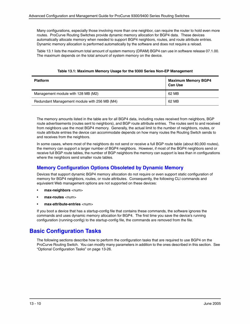
Table 13.1 lists the maximum total amount of system memory (DRAM) BGP4 can use in software release 07.1.00. The maximum depends on the total amount of system memory on the device.
Table 13.1: Maximum Memory Usage for the 9300 Series Non-EP Management
Platform Maximum Memory BGP4 Can Use
Management module with 128 MB (M2) 62 MB
Redundant Management module with 256 MB (M4) 62 MB
The memory amounts listed in the table are for all BGP4 data, including routes received from neighbors, BGP route advertisements (routes sent to neighbors), and BGP route attribute entries. The routes sent to and received from neighbors use the most BGP4 memory. Generally, the actual limit to the number of neighbors, routes, or route attribute entries the device can accommodate depends on how many routes the Routing Switch sends to and receives from the neighbors.
In some cases, where most of the neighbors do not send or receive a full BGP route table (about 80,000 routes), the memory can support a larger number of BGP4 neighbors. However, if most of the BGP4 neighbors send or receive full BGP route tables, the number of BGP neighbors the memory can support is less than in configurations where the neighbors send smaller route tables.
Memory Configuration Options Obsoleted by Dynamic Memory Devices that support dynamic BGP4 memory allocation do not require or even support static configuration of memory for BGP4 neighbors, routes, or route attributes. Consequently, the following CLI commands and equivalent Web management options are not supported on these devices:
• max-neighbors <num>
• max-routes <num>
• max-attribute-entries <num>
If you boot a device that has a startup-config file that contains these commands, the software ignores the commands and uses dynamic memory allocation for BGP4. The first time you save the device’s running configuration (running-config) to the startup-config file, the commands are removed from the file.
Basic Configuration Tasks The following sections describe how to perform the configuration tasks that are required to use BGP4 on the ProCurve Routing Switch. You can modify many parameters in addition to the ones described in this section. See “Optional Configuration Tasks” on page 13-26.
13 - 10 June 2005
Configuring BGP4
Enabling BGP4 on the Router When you enable BGP4 on the router, BGP4 is automatically activated. To enable BGP4 on the router, enter the following commands:
USING THE CLI
ProCurveRS> enable ProCurveRS# configure terminal ProCurveRS(config)# router bgp BGP4: Please configure 'local-as' parameter in order to enable BGP4. ProCurveRS(config-bgp-router)# local-as 10 ProCurveRS(config-bgp-router)# neighbor 209.157.23.99 remote-as 100 ProCurveRS(config-bgp-router)# write memory
USING THE WEB MANAGEMENT INTERFACE
1. Log on to the device using a valid user name and password for read-write access. The System configuration panel is displayed.
2. Select the Enable radio button next to BGP.
3. Enter the local AS number in the Local AS field.
4. Click the Apply button to apply the changes to the device’s running-config file.
5. Select the Save link at the bottom of the dialog. Select Yes when prompted to save the configuration change to the startup-config file on the device’s flash memory.
Changing the Router ID The OSPF and BGP4 protocols use router IDs to identify the routers that are running the protocols. A router ID is a valid, unique IP address and sometimes is an IP address configured on the router. The router ID cannot be an IP address in use by another device.
By default, the router ID on a ProCurve Routing Switch is one of the following:
• If the router has loopback interfaces, the default router ID is the IP address configured on the lowest numbered loopback interface configured on the Routing Switch. For example, if you configure loopback interfaces 1, 2, and 3 as follows, the default router ID is 9.9.9.9/24:
• Loopback interface 1, 9.9.9.9/24
• Loopback interface 2, 4.4.4.4/24
• Loopback interface 3, 1.1.1.1/24
• If the device does not have any loopback interfaces, the default router ID is the lowest numbered IP interface address configured on the device.
NOTE: ProCurve Routing Switches use the same router ID for both OSPF and BGP4. If the router is already configured for OSPF, you may want to use the router ID that is already in use on the router rather than set a new one. To display the router ID, enter the show ip CLI command at any CLI level or select the IP->General links from the Configure tree in the Web management interface.
USING THE CLI
To change the router ID, enter a command such as the following:
ProCurveRS(config)# ip router-id 209.157.22.26
Syntax: ip router-id <ip-addr>
The <ip-addr> can be any valid, unique IP address.
NOTE: You can specify an IP address used for an interface on the ProCurve Routing Switch, but do not specify an IP address in use by another device.
June 2005 13 - 11

Advanced Configuration and Management Guide for ProCurve 9300/9400 Series Routing Switches
USING THE WEB MANAGEMENT INTERFACE
1. Log on to the device using a valid user name and password for read-write access. The System configuration panel is displayed.
2. Click on the plus sign next to Configure in the tree view to expand the list of configuration options.
3. Click on the plus sign next to IP in the tree view to expand the list of IP option links.
4. Click on the General link to display the IP configuration panel.
5. Edit the value in the Router ID field. Specify a valid IP address that is not in use on another device in the network.
6. Click the Apply button to save the change to the device’s running-config file.
7. Select the Save link at the bottom of the dialog. Select Yes when prompted to save the configuration change to the startup-config file on the device’s flash memory.
Setting the Local AS Number The local AS number identifies the AS the HP BGP4 router is in. The AS number can be from 1 – 65535. There is no default. AS numbers 64512 – 65535 are the well-known private BGP4 AS numbers and are not advertised to the Internet community.
To set the local AS number, use either of the following methods.
USING THE CLI
To set the local AS number, enter commands such as the following:
ProCurveRS(config)# router bgp BGP4: Please configure 'local-as' parameter in order to enable BGP4. ProCurveRS(config-bgp-router)# local-as 10 ProCurveRS(config-bgp-router)# write memory
Syntax: [no] local-as <num>
The <num> parameter specifies the local AS number.
USING THE WEB MANAGEMENT INTERFACE
1. Log on to the device using a valid user name and password for read-write access. The System configuration panel is displayed.
2. Select the Enable radio button next to BGP.
3. Enter the local AS number in the Local AS field.
4. Click the Apply button to apply the changes to the device’s running-config file.
5. Select the Save link at the bottom of the dialog. Select Yes when prompted to save the configuration change to the startup-config file on the device’s flash memory.
Adding a Loopback Interface You can configure the router to use a loopback interface instead of a specific port or virtual routing interface to communicate with a BGP4 neighbor. A loopback interface adds stability to the network by working around route flap problems that can occur due to unstable links between the router and its neighbors.
Loopback interfaces are always up, regardless of the states of physical interfaces. Loopback interfaces are especially useful for IBGP neighbors (neighbors in the same AS) that are multiple hops away from the router. When you configure a BGP4 neighbor on the router, you can specify whether the router uses the loopback interface to communicate with the neighbor. As long as a path exists between the router and its neighbor, BGP4 information can be exchanged. The BGP4 session is not associated with a specific link but instead is associated with the virtual interfaces.
You can add up to 24 IP addresses to each loopback interface.
13 - 12 June 2005

Configuring BGP4
NOTE: If you configure the ProCurve Routing Switch to use a loopback interface to communicate with a BGP4 neighbor, the peer IP address on the remote router pointing to your loopback address must be configured.
To add a loopback interface, use one of the following methods.
USING THE CLI
To add a loopback interface, enter commands such as those shown in the following example:
ProCurveRS(config-bgp-router)# exit
ProCurveRS(config)# int loopback 1
ProCurveRS(config-lbif-1)# ip address 10.0.0.1/24
Syntax: interface loopback <num>
The <num> value can be from 1 – 8.
USING THE WEB MANAGEMENT INTERFACE
1. Log on to the device using a valid user name and password for read-write access. The System configuration panel is displayed.
2. Select the IP Address link to display a table listing the configured IP addresses.
3. Select the Loop Back link.
NOTE: If the device already has loopback interfaces, a table listing the interfaces is displayed. Click the Modify button to the right of the row describing an interface to change its configuration, or click the Add Loop Back link to display the Router Loop Back configuration panel.
4. Select the loopback interface number from the Loopback field’s pulldown menu. You can select from 1 – 8.
5. Select the status. The interface is enabled by default.
6. Click Add to add the new interface.
7. Click on Configure in the tree view to display the configuration options.
8. Click on IP to display the IP configuration options.
9. Select the Add IP Address link to display the Router IP Address panel.
10. Select the loopback interface from the Port field’s pulldown menu. For example, to select loopback interface 1, select “lb1”.
11. Enter the loopback interface’s IP address in the IP Address field.
12. Enter the network mask in the Subnet Mask field.
13. Click the Add button to save the change to the device’s running-config file.
14. Select the Save link at the bottom of the dialog. Select Yes when prompted to save the configuration change to the startup-config file on the device’s flash memory.
Adding BGP4 Neighbors The BGP4 protocol does not contain a peer discovery process. Therefore, for each of the router’s BGP4 neighbors (peers), you must indicate the neighbor’s IP address and the AS each neighbor is in. Neighbors that are in different ASs communicate using EBGP. Neighbors within the same AS communicate using IBGP.
NOTE: If the Routing Switch has multiple neighbors with similar attributes, you can simplify configuration by configuring a peer group, then adding individual neighbors to it. The configuration steps are similar, except you specify a peer group name instead of a neighbor IP address when configuring the neighbor parameters, then add individual neighbors to the peer group. See “Adding a BGP4 Peer Group” on page 13-21.
June 2005 13 - 13

Advanced Configuration and Management Guide for ProCurve 9300/9400 Series Routing Switches
NOTE: The Routing Switch attempts to establish a BGP4 session with a neighbor as soon as you enter a command specifying the neighbor’s IP address. If you want to completely configure the neighbor parameters before the Routing Switch establishes a session with the neighbor, you can administratively shut down the neighbor. See “Administratively Shutting Down a Session with a BGP4 Neighbor” on page 13-25.
USING THE CLI
To add a BGP4 neighbor with IP address 209.157.22.26, enter the following command:
ProCurveRS(config-bgp-router)# neighbor 209.157.22.26
The neighbor’s <ip-addr> must be a valid IP address.
The neighbor command has some additional parameters, as shown in the following syntax:
Syntax: [no] neighbor <ip-addr> | <peer-group-name>[advertisement-interval <num>] [capability orf prefixlist [send | receive]] [default-originate [route-map <map-name>]] [description <string>][distribute-list in | out <num,num,...> | <acl-num> in | out] [ebgp-multihop [<num>]][filter-list in | out <num,num,...> | <acl-num> in | out | weight] [maximum-prefix <num> [<threshold>] [teardown]] [next-hop-self] [nlri multicast | unicast | multicast unicast] [password [0 | 1] <string>] [prefix-list <string> in | out] [remote-as <as-number>][remove-private-as] [route-map in | out <map-name>][route-reflector-client][send-community] [soft-reconfiguration inbound][shutdown][timers keep-alive <num> hold-time <num>] [unsuppress-map <map-name>][update-source <ip-addr> | ethernet <portnum> | loopback <num> | ve <num>][weight <num>]
The <ip-addr> | <peer-group-name> parameter indicates whether you are configuring an individual neighbor or apeer group. If you specify a neighbor’s IP address, you are configuring that individual neighbor. If you specify a peer group name, you are configuring a peer group. See “Adding a BGP4 Peer Group” on page 13-21.
advertisement-interval <num> specifies the minimum delay (in seconds) between messages to the specified neighbor. The default is 30 for EBGP neighbors (neighbors in other ASs). The default is 5 for IBGP neighbors (neighbors in the same AS). The range is 0 – 600.
NOTE: The Routing Switch applies the advertisement interval only under certain conditions. The Routing Switch does not apply the advertisement interval when sending initial updates to a BGP4 neighbor. As a result, the Routing Switch sends the updates one immediately after another, without waiting for the advertisement interval.
capability orf prefixlist [send | receive] configures cooperative router filtering. The send | receive parameter specifies the support you are enabling:
• send – The Routing Switch sends the IP prefix lists as Outbound Route Filters (ORFs) to the neighbor.
• receive – The Routing Switch accepts filters as Outbound Route Filters (ORFs) from the neighbor.
If you do not specify the capability, both capabilities are enabled. The prefixlist parameter specifies the type offilter you want to send to the neighbor.
For more information, see “Configuring Cooperative BGP4 Route Filtering” on page 13-80.
13 - 14 June 2005

Configuring BGP4
NOTE: The current release supports cooperative filtering only for filters configured using IP prefix lists.
default-originate [route-map <map-name>] configures the Routing Switch to send the default route 0.0.0.0 to the neighbor. If you use the route-map <map-name> parameter, the route map injects the default route conditionally, based on the match conditions in the route map.
description <string> specifies a name for the neighbor. You can enter an alphanumeric text string up to 80 characters long.
distribute-list in | out <num,num,...> specifies a distribute list to be applied to updates to or from the specified neighbor. The in | out keyword specifies whether the list is applied on updates received from the neighbor or sent to the neighbor. The <num,num,...> parameter specifies the list of address-list filters. The router applies the filters in the order in which you list them and stops applying the filters in the distribute list when a match is found.
Alternatively, you can specify distribute-list <acl-num> in | out to use an IP ACL instead of a distribute list. In this case, <acl-num> is an IP ACL.
NOTE: By default, if a route does not match any of the filters, the Routing Switch denies the route. To change the default behavior, configure the last filter as “permit any any”.
NOTE: The address filter must already be configured. See “Filtering Specific IP Addresses” on page 13-52.
ebgp-multihop [<num>] specifies that the neighbor is more than one hop away and that the session type with the neighbor is thus EBGP-multihop. This option is disabled by default. The <num> parameter specifies the TTL you are adding for the neighbor. You can specify a number from 0 – 255. The default is 0. If you leave the EBGP TTL value set to 0, the software uses the IP TTL value.
filter-list in | out <num,num,...> specifies an AS-path filter list or a list of AS-path ACLs. The in | out keyword specifies whether the list is applied on updates received from the neighbor or sent to the neighbor. If you specify in or out, The <num,num,...> parameter specifies the list of AS-path filters. The router applies the filters in the order in which you list them and stops applying the filters in the AS-path filter list when a match is found. The weight <num> parameter specifies a weight that the Routing Switch applies to routes received from the neighbor that match the AS-path filter or ACL. You can specify a number from 0 – 65535.
Alternatively, you can specify filter-list <acl-num> in | out | weight to use an AS-path ACL instead of an AS-path filter list. In this case, <acl-num> is an AS-path ACL.
NOTE: By default, if an AS-path does not match any of the filters or ACLs, the Routing Switch denies the route. To change the default behavior, configure the last filter or ACL as “permit any any”.
NOTE: The AS-path filter or ACL must already be configured. See “Filtering AS-Paths” on page 13-54.
maximum-prefix <num> specifies the maximum number of IP network prefixes (routes) that can be learned from the specified neighbor or peer group. You can specify a value from 0 – 4294967295. The default is 0 (unlimited).
• The <num> parameter specifies the maximum number. You can specify a value from 0 – 4294967295. The default is 0 (unlimited).
• The <threshold> parameter specifies the percentage of the value you specified for the maximum-prefix <num>, at which you want the software to generate a Syslog message. You can specify a value from 1 (one percent) to 100 (100 percent). The default is 100.
• The teardown parameter tears down the neighbor session if the maximum-prefix limit is exceeded. The session remains shutdown until you clear the prefixes using the clear ip bgp neighbor all or clear ip bgp neighbor <ip-addr> command, or change the neighbor’s maximum-prefix configuration. The software also generates a Syslog message.
next-hop-self specifies that the router should list itself as the next hop in updates sent to the specified neighbor. This option is disabled by default.
June 2005 13 - 15

Advanced Configuration and Management Guide for ProCurve 9300/9400 Series Routing Switches
The nlri multicast | unicast | multicast unicast parameter specifies whether the neighbor is a multicast neighbor or a unicast neighbor. For MBGP, you must specify multicast. Optionally, you also can specify unicast if you want the Routing Switch to exchange unicast (BGP4) routes as well as multicast routes with the neighbor. The default is unicast only. For more information, see “Configuring MBGP (9300 Series Only)” on page 14-1.
password [0 | 1] <string> specifies an MD5 password for securing sessions between the Routing Switch and the neighbor. You can enter a string up to 80 characters long. The string can contain any alphanumeric characters, but the first character cannot be a number. If the password contains a number, do not enter a space following the number.
The 0 | 1 parameter is the encryption option, which you can omit (the default) or which can be one of the following.
• 0 – Disables encryption for the authentication string you specify with the command. The password or string is shown as clear text in the output of commands that display neighbor or peer group configuration information.
• 1 – Assumes that the authentication string you enter is the encrypted form, and decrypts the value before using it.
For more information, see “Encryption of BGP4 MD5 Authentication Keys” on page 13-20.
NOTE: If you want the software to assume that the value you enter is the clear-text form, and to encrypt display of that form, do not enter 0 or 1. Instead, omit the encryption option and allow the software to use the default behavior.
If you specify encryption option 1, the software assumes that you are entering the encrypted form of the password or authentication string. In this case, the software decrypts the password or string you enter before using the value for authentication. If you accidentally enter option 1 followed by the clear-text version of the password or string, authentication will fail because the value used by the software will not match the value you intended to use.
prefix-list <string> in | out specifies an IP prefix list. You can use IP prefix lists to control routes to and from the neighbor. IP prefix lists are an alternative method to AS-path filters. The in | out keyword specifies whether the list is applied on updates received from the neighbor or sent to the neighbor. You can configure up to 1000 prefix list filters. The filters can use the same prefix list or different prefix lists. To configure an IP prefix list, see “Defining IP Prefix Lists” on page 13-63.
remote-as <as-number> specifies the AS the remote neighbor is in. The <as-number> can be a number from 1 – 65535. There is no default.
remove-private-as configures the router to remove private AS numbers from UPDATE messages the router sends to this neighbor. The router will remove AS numbers 64512 – 65535 (the well-known BGP4 private AS numbers) from the AS-path attribute in UPDATE messages the Routing Switch sends to the neighbor. This option is disabled by default.
route-map in | out <map-name> specifies a route map the Routing Switch will apply to updates sent to or received from the specified neighbor. The in | out keyword specifies whether the list is applied on updates received from the neighbor or sent to the neighbor.
NOTE: The route map must already be configured. See “Defining Route Maps” on page 13-68.
route-reflector-client specifies that this neighbor is a route-reflector client of the router. Use the parameter only if this router is going to be a route reflector. For information, see “Configuring Route Reflection Parameters” on page 13-40. This option is disabled by default.
send-community enables sending the community attribute in updates to the specified neighbor. By default, the router does not send the community attribute.
shutdown administratively shuts down the session with this neighbor. Shutting down the session allows you to completely configure the neighbor and save the configuration without actually establishing a session with the neighbor. This option is disabled by default.
soft-reconfiguration inbound enables the soft reconfiguration feature, which stores all the route updates received from the neighbor. If you request a soft reset of inbound routes, the software performs the reset by
13 - 16 June 2005
Configuring BGP4
comparing the policies against the stored route updates, instead of requesting the neighbor’s BGP4 route table or resetting the session with the neighbor. See “Using Soft Reconfiguration” on page 13-133.
timers keep-alive <num> hold-time <num> overrides the global settings for the Keep Alive Time and Hold Time. For the Keep Alive Time, you can specify from 0 – 65535 seconds. For the Hold Time, you can specify 0 or 3 – 65535 (1 and 2 are not allowed). If you set the Hold Time to 0, the router waits indefinitely for messages from a neighbor without concluding that the neighbor is dead. The defaults for these parameters are the currently configured global Keep Alive Time and Hold Time. For more information about these parameters, see “Changing the Keep Alive Time and Hold Time” on page 13-26.
unsuppress-map <map-name> removes route dampening from a neighbor’s routes when those routes have been dampened due to aggregation. See “Removing Route Dampening from a Neighbor’s Routes Suppressed Due to Aggregation” on page 13-93.
update-source <ip-addr> | ethernet <portnum> | loopback <num> | ve <num> configures the router to communicate with the neighbor through the specified interface. There is no default.
weight <num> specifies a weight the Routing Switch will add to routes received from the specified neighbor. BGP4 prefers larger weights over smaller weights. The default weight is 0.
USING THE WEB MANAGEMENT INTERFACE
1. Log on to the device using a valid user name and password for read-write access. The System configuration panel is displayed.
2. Click on the plus sign next to Configure in the tree view to expand the list of configuration options.
3. Click on the plus sign next to BGP in the tree view to expand the list of BGP option links.
June 2005 13 - 17

Advanced Configuration and Management Guide for ProCurve 9300/9400 Series Routing Switches
4. Click on the Neighbor link to display the BGP Neighbor panel.
NOTE: If the device already has neighbors, a table listing the neighbors is displayed. Click the Modify button to the right of the row describing the neighbor to change its configuration, or click the Add Neighbor link to display the BGP Neighbor configuration panel.
5. Enter the neighbor’s IP address in the IP Address field.
6. Enter a description in the Description field.
7. Select Enable next to Default Originate if you want to enable this feature for the neighbor. By default, the Routing Switch does not advertise a default route using BGP4. A BGP4 default route is the IP address 0.0.0.0 and the route prefix 0 or network mask 0.0.0.0. For example, 0.0.0.0/0 is a default route.
8. Select the checkbox next to Default Originate Route Map and select a route map from the pulldown menu if you want to use a route map to control advertisement of default routes.
9. Select Enable next to EBGP Multihop if the neighbor is multiple EBGP hops away.
10. If you enabled EBGP Multihop, enter the TTL for EBGP multihop in the EBGP Multihop TTL field. You can specify a number from 0 – 255. The default is 0. If you leave the EBGP TTL value set to 0, the software uses the IP TTL value.
11. Select Enable next to Next Hop Self if the router should list itself as the next hop in updates sent to the neighbor. This option is disabled by default.
13 - 18 June 2005

Configuring BGP4
12. Select Enable next to Send Community if you want to send the community attribute in updates to the neighbor. By default, the router does not send the community attribute.
13. Select Enable next to Remove Private AS if you want the router to remove private AS numbers from UPDATE messages the router sends to this neighbor. The router will remove AS numbers 64512 – 65535 (the wellknown BGP4 private AS numbers) from the AS-path attribute in UPDATE messages the Routing Switch sends to the neighbor. This option is disabled by default.
14. Select Enable next to Client To Client Reflection if this neighbor is a route-reflector client of the router. Use the parameter only if this router is going to be a route reflector. For information, see “Configuring Route Reflection Parameters” on page 13-40. This option is disabled by default.
15. Select Enable next to Shutdown if you want to administratively shut down the session with this neighbor. Shutting down the session allows you to completely configure the neighbor and save the configuration without actually establishing a session with the neighbor. This option is disabled by default.
16. Enter the advertisement interval in the Advert Interval field. This parameter specifies the minimum delay (in seconds) between messages to the specified neighbor. The default is 30 for EBGP neighbors (neighbors in other ASs). The default is 5 for IBGP neighbors (neighbors in the same AS). The range is 0 – 600.
17. Edit the value in the Maximum Prefix field to change the maximum prefix. The maximum prefix is the maximum number of IP network prefixes (routes) that can be learned from the specified neighbor. The default is 0 (unlimited). The range is 0 – 4294967295.
18. Enter the remote AS number in the Remote AS field. The remote AS number is the number of the AS the neighbor is in.
19. Enter the weight you want the Routing Switch to add to routes received from the specified neighbor. BGP4 prefers larger weights over smaller weights. The default weight is 0.
20. Enter the number of an update source loopback interface in the Update Source field. This parameter configures the router to communicate with the neighbor through the loopback address on the specified interface. Using a loopback address for neighbor communication avoids problems that can be caused by unstable router interfaces. Generally, loopback interfaces are used for links to IBGP neighbors, which often are multiple hops away, rather than EBGP neighbors. The loopback interface number can be from 1 – 8. There is no default.
21. Enter a Keep Alive time in the Keep Alive Time field. This parameter overrides the global BGP4 Keep Alive Time configured on the Routing Switch. You can specify from 0 – 65535 seconds. The default is the current global setting.
22. Enter a Hold Time in the Hold Time field. This parameter overrides the global BGP4 Hold Time configured on the Routing Switch. You can specify 0 or 3 – 65535 (1 and 2 are not allowed). If you set the Hold Time to 0, the router waits indefinitely for messages from a neighbor without concluding that the neighbor is dead. The default is the current global setting.
NOTE: Set the Hold Time to three times the value of the Keep Alive Time. For information about these parameters, see “Changing the Keep Alive Time and Hold Time” on page 13-26.
23. If you specified a weight in the Weight field, enter a list of AS Path filters in the AS Path Filter List for Weight field. The router applies the filters in the order in which you list them and stops applying the filters in the ASpath filter list when a match is found.
NOTE: By default, if an AS-path does not match any of the filters, the Routing Switch denies the route. To change the default behavior, configure the last filter as “permit any any”.
NOTE: The AS-path filter must already be configured. See “Filtering AS-Paths” on page 13-54.
24. Enter a password in the MD5 Password field to secure the Routing Switch’s sessions with this neighbor.
June 2005 13 - 19
Advanced Configuration and Management Guide for ProCurve 9300/9400 Series Routing Switches
NOTE: You must configure the neighbor to use the same password.
25. Click the Add button (if you are adding a new neighbor) or the Modify button (if you are modifying a neighbor that is already configured) to apply the changes to the device’s running-config file.
26. Select the Save link at the bottom of the dialog, then select Yes when prompted to save the configuration change to the startup-config file on the device’s flash memory.
Encryption of BGP4 MD5 Authentication Keys
When you configure a BGP4 neighbor or neighbor peer group, you can specify an MD5 authentication string for authenticating packets exchanged with the neighbor or peer group of neighbors.
For added security, the software encrypts display of the authentication string by default. The software also provides an optional parameter to disable encryption of the authentication string, on an individual neighbor or peer group basis. By default, the MD5 authentication strings are displayed in encrypted format in the output of the following commands:
• show running-config (or write terminal)
• show configuration
• show ip bgp config
When encryption of the authentication string is enabled, the string is encrypted in the CLI regardless of the access level you are using.
Encryption Example The following commands configure a BGP4 neighbor and a peer group, and specify MD5 authentication strings (passwords) for authenticating packets exchanged with the neighbor or peer group.
ProCurveRS(config-bgp-router)# local-as 2 ProCurveRS(config-bgp-router)# neighbor xyz peer-group ProCurveRS(config-bgp-router)# neighbor xyz password abc ProCurveRS(config-bgp-router)# neighbor 10.10.200.102 peer-group xyz ProCurveRS(config-bgp-router)# neighbor 10.10.200.102 password test
Here is how the commands appear when you display the BGP4 configuration commands:
ProCurveRS(config-bgp-router)# show ip bgp config Current BGP configuration: router bgp local-as 2 neighbor xyz peer-group neighbor xyz password 1 $!2d neighbor 10.10.200.102 peer-group xyz neighbor 10.10.200.102 remote-as 1 neighbor 10.10.200.102 password 1 $on-o
Notice that the software has converted the commands that specify an authentication string into the new syntax (described below), and has encrypted display of the authentication strings.
Command Syntax Since the default behavior in software release 07.1.14 does not affect the BGP4 configuration itself but does encrypt display of the authentication string, the CLI does not list the encryption options.
Syntax: [no] neighbor <ip-addr> | <peer-group-name> password [0 | 1] <string>
13 - 20 June 2005
Configuring BGP4
The <ip-addr> | <peer-group-name> parameter indicates whether you are configuring an individual neighbor or a peer group. If you specify a neighbor’s IP address, you are configuring that individual neighbor. If you specify a peer group name, you are configuring a peer group.
The password <string> parameter specifies an MD5 authentication string for securing sessions between the Routing Switch and the neighbor. You can enter a string up to 80 characters long. The string can contain any alphanumeric characters, but the first character cannot be a number. If the password contains a number, do not enter a space following the number.
The 0 | 1 parameter is the encryption option, which you can omit (the default) or which can be one of the following.
• 0 – Disables encryption for the authentication string you specify with the command. The password or string is shown as clear text in the output of commands that display neighbor or peer group configuration information.
• 1 – Assumes that the authentication string you enter is the encrypted form, and decrypts the value before using it.
NOTE: If you want the software to assume that the value you enter is the clear-text form, and to encrypt display of that form, do not enter 0 or 1. Instead, omit the encryption option and allow the software to use the default behavior.
If you specify encryption option 1, the software assumes that you are entering the encrypted form of the password or authentication string. In this case, the software decrypts the password or string you enter before using the value for authentication. If you accidentally enter option 1 followed by the clear-text version of the password or string, authentication will fail because the value used by the software will not match the value you intended to use.
Displaying the Authentication String If you want to display the authentication string, enter the following commands:
ProCurveRS(config)# enable password-display ProCurveRS(config)# show ip bgp neighbors
The enable password-display command enables display of the authentication string, but only in the output of the show ip bgp neighbors command. Display of the string is still encrypted in the startup-config file and runningconfig. Enter the command at the global CONFIG level of the CLI.
NOTE: The command also displays SNMP community strings in clear text, in the output of the show snmp server command.
Adding a BGP4 Peer Group A peer group is a set of BGP4 neighbors that share common parameters. Peer groups provide the following benefits:
• Simplified neighbor configuration – You can configure a set of neighbor parameters and then apply them to multiple neighbors. You do not need to individually configure the common parameters individually on each neighbor.
• Flash memory conservation – Using peer groups instead of individually configuring all the parameters for each neighbor requires fewer configuration commands in the startup-config file.
You can perform the following tasks on a peer-group basis.
• Reset neighbor sessions
• Perform soft-outbound resets (the Routing Switch updates outgoing route information to neighbors but does not entirely reset the sessions with those neighbors)
• Clear BGP message statistics
• Clear error buffers
June 2005 13 - 21
Advanced Configuration and Management Guide for ProCurve 9300/9400 Series Routing Switches
Peer Group Parameters
You can set all neighbor parameters in a peer group. When you add a neighbor to the peer group, the neighbor receives all the parameter settings you set in the group, except parameter values you have explicitly configured for the neighbor. If you do not set a neighbor parameter in the peer group and the parameter also is not set for the individual neighbor, the neighbor uses the default value.
Configuration Rules
The following rules apply to peer group configuration:
• You must configure a peer group before you can add neighbors to the peer group.
• If you remove a parameter from a peer group, the value for that parameter is reset to the default for all the neighbors within the peer group, unless you have explicitly set that parameter on individual neighbors. In this case, the value you set on the individual neighbors applies to those neighbors, while the default value applies to neighbors for which you have not explicitly set the value.
NOTE: If you enter a command to remove the remote AS parameter from a peer group, the software checks to ensure that the peer group does not contain any neighbors. If the peer group does contain neighbors, the software does not allow you to remove the remote AS. The software prevents removing the remote AS in this case so that the neighbors in the peer group that are using the remote AS do not lose connectivity to the Routing Switch.
• Once you add a neighbor to a peer group, you cannot configure the following outbound parameters (the parameters governing outbound traffic) for the neighbor.
• Default-information-originate
• Next-hop-self
• Outbound route map
• Outbound filter list
• Outbound distribute list
• Outbound prefix list
• Remote AS, if configured for the peer group
• Remove private AS
• Route reflector client
• Send community
• Timers
• Update source
If you want to change an outbound parameter for an individual neighbor, you must first remove the neighbor from the peer group. In this case, you cannot re-add the neighbor to the same peer group, but you can add the neighbor to a different peer group. All the neighbors within a peer group must have the same values for the outbound parameters. To change an outbound parameter to the same value for all neighbors within a peer group, you can change the parameter on a peer-group basis. In this case, you do not need to remove the neighbors and change the parameter individually for each neighbor.
• If you add an outbound parameter to a peer group, that parameter is automatically applied to all neighbors within the peer group.
• When you add a neighbor to a peer group, the software removes any outbound parameters for that neighbor from the running configuration (running-config). As a result, when you save the configuration to the startupconfig file, the file does not contain any outbound parameters for the individual neighbors you have placed in a peer group. The only outbound parameters the startup-config file contains for neighbors within a peer group are the parameters associated with the peer group itself. However, the running-config and the startupconfig file can contain individual parameters listed in the previous section as well as the settings for those parameters within a peer group.
13 - 22 June 2005

Configuring BGP4
You can override neighbor parameters that do not affect outbound policy on an individual neighbor basis.
• If you do not specify a parameter for an individual neighbor, the neighbor uses the value in the peer group.
• If you set the parameter for the individual neighbor, that value overrides the value you set in the peer group.
• If you add a parameter to a peer group that already contains neighbors, the parameter value is applied to neighbors that do not already have the parameter explicitly set. If a neighbor has the parameter explicitly set, the explicitly set value overrides the value you set for the peer group.
• If you remove the setting for a parameter from a peer group, the value for that parameter changes to the default value for all the neighbors in the peer group that do not have that parameter individually set.
Configuring a Peer Group
To configure a BGP4 peer group, use either of the following methods.
USING THE CLI
To configure a peer group, enter commands such as the following at the BGP configuration level:
ProCurveRS(config-bgp-router)# neighbor PeerGroup1 peer-group ProCurveRS(config-bgp-router)# neighbor PeerGroup1 description “EastCoast Neighbors”ProCurveRS(config-bgp-router)# neighbor PeerGroup1 remote-as 100 ProCurveRS(config-bgp-router)# neighbor PeerGroup1 distribute-list out 1
The commands in this example configure a peer group called “PeerGroup1” and set the following parameters for the peer group:
• A description, “EastCoast Neighbors”
• A remote AS number, 100
• A distribute list for outbound traffic
The software applies these parameters to each neighbor you add to the peer group. You can override the description parameter for individual neighbors. If you set the description parameter for an individual neighbor, the description overrides the description configured for the peer group. However, you cannot override the remote AS and distribute list parameters for individual neighbors. Since these parameters control outbound traffic, the parameters must have the same values for all neighbors within the peer group.
Syntax: neighbor <peer-group-name> peer-group
The <peer-group-name> parameter specifies the name of the group and can be up to 80 characters long. The name can contain special characters and internal blanks. If you use internal blanks, you must use quotation marks around the name. For example, the command neighbor “My Three Peers” peer-group is valid, but the command neighbor My Three Peers peer-group is not valid.
June 2005 13 - 23

Advanced Configuration and Management Guide for ProCurve 9300/9400 Series Routing Switches
Syntax: [no] neighbor <ip-addr> | <peer-group-name>[advertisement-interval <num>] [default-originate [route-map <map-name>]] [description <string>][distribute-list in | out <num,num,...> | <acl-num> in | out] [ebgp-multihop [<num>]][filter-list in | out <num,num,...> | <acl-num> in | out | weight] [maximum-prefix <num> [<threshold>] [teardown]] [next-hop-self] [password [0 | 1] <string>] [prefix-list <string> in | out] [remote-as <as-number>][remove-private-as] [route-map in | out <map-name>][route-reflector-client][send-community] [soft-reconfiguration inbound][shutdown][timers keep-alive <num> hold-time <num>] [update-source loopback <num>][weight <num>]
Syntax: The <ip-addr> | <peer-group-name> parameter indicates whether you are configuring a peer group or anindividual neighbor. You can specify a peer group name or IP address with the neighbor command. If youspecify a peer group name, you are configuring a peer group. If you specify a neighbor’s IP address, you areconfiguring that individual neighbor. Use the <ip-addr> parameter if you are configuring an individual neighbor instead of a peer group. See “Adding BGP4 Neighbors” on page 13-13.
The remaining parameters are the same ones supported for individual neighbors. See “Adding BGP4 Neighbors” on page 13-13.
USING THE WEB MANAGEMENT INTERFACE
You cannot configure peer group parameters using the Web management interface.
Applying a Peer Group to a Neighbor
After you configure a peer group, you can add neighbors to the group. When you add a neighbor to a peer group, you are applying all the neighbor attributes specified in the peer group to the neighbor.
To add a neighbor to a peer group, use either of the following methods.
USING THE CLI
To add neighbors to a peer group, enter commands such as the following:
ProCurveRS(config-bgp-router)# neighbor 192.168.1.12 peer-group PeerGroup1 ProCurveRS(config-bgp-router)# neighbor 192.168.2.45 peer-group PeerGroup1 ProCurveRS(config-bgp-router)# neighbor 192.168.3.69 peer-group PeerGroup1
The commands in this example add three neighbors to the peer group “PeerGroup1”. As members of the peer group, the neighbors automatically receive the neighbor parameter values configured for the peer group. You also can override the parameters (except parameters that govern outbound traffic) on an individual neighbor basis. For neighbor parameters not specified for the peer group, the neighbors use the default values.
Syntax: neighbor <ip-addr> peer-group <peer-group-name>
The <ip-addr> parameter specifies the IP address of the neighbor.
The <peer-group-name> parameter specifies the peer group name.
NOTE: You must add the peer group before you can add neighbors to it.
13 - 24 June 2005
Configuring BGP4
USING THE WEB MANAGEMENT INTERFACE
You cannot configure peer group parameters using the Web management interface.
Administratively Shutting Down a Session with a BGP4 Neighbor
You can prevent the Routing Switch from starting a BGP4 session with a neighbor by administratively shutting down the neighbor. This option is very useful for situations in which you want to configure parameters for a neighbor but are not ready to use the neighbor. You can shut the neighbor down as soon as you have added it the Routing Switch, configure the neighbor parameters, then allow the Routing Switch to reestablish a session with the neighbor by removing the shutdown option from the neighbor.
When you apply the new option to shut down a neighbor, the option takes place immediately and remains in effect until you remove the option. If you save the configuration to the startup-config file, the shutdown option remains in effect even after a software reload.
NOTE: The software also contains an option to end the session with a BGP4 neighbor and thus clear the routes learned from the neighbor. Unlike this clear option, the option for shutting down the neighbor can be saved in the startup-config file and thus can prevent the Routing Switch from establishing a BGP4 session with the neighbor even after reloading the software.
NOTE: If you notice that a particular BGP4 neighbor never establishes a session with the ProCurve Routing Switch, check the Routing Switch’s running-config and startup-config files to see whether the configuration contains a command that is shutting down the neighbor. The neighbor may have been shut down previously by an administrator.
To shut down a BGP4 neighbor, use either of the following methods.
USING THE CLI
To shut down a BGP4 neighbor, enter commands such as the following:
ProCurveRS(config)# router bgp ProCurveRS(config-bgp-router)# neighbor 209.157.22.26 shutdown ProCurveRS(config-bgp-router)# write memory
Syntax: [no] neighbor <ip-addr> shutdown
The <ip-addr> parameter specifies the IP address of the neighbor.
USING THE WEB MANAGEMENT INTERFACE
1. Log on to the device using a valid user name and password for read-write access. The System configuration panel is displayed.
2. Click on the plus sign next to Configure in the tree view to expand the list of configuration options.
3. Click on the plus sign next to BGP in the tree view to expand the list of BGP option links.
4. Click on the Neighbor link to display the BGP Neighbor panel.
NOTE: If the device already has neighbors, a table listing the neighbors is displayed. Click the Modify button to the right of the row describing the neighbor to change its configuration, or click the Add Neighbor link to display the BGP Neighbor configuration panel.
5. Enter or modify parameters as needed. For detailed information, see “Adding BGP4 Neighbors” on page 1313.
6. Select the Enable radio button next to Shutdown.
7. Click the Add button (if you are adding a new neighbor) or the Modify button (if you are modifying a neighbor that is already configured) to apply the changes to the device’s running-config file.
8. Select the Save link at the bottom of the dialog, then select Yes when prompted to save the configuration change to the startup-config file on the device’s flash memory.
June 2005 13 - 25
Advanced Configuration and Management Guide for ProCurve 9300/9400 Series Routing Switches
Optional Configuration Tasks The following sections describe how to perform optional BGP4 configuration tasks.
Changing the Keep Alive Time and Hold Time The Keep Alive Time specifies how frequently the router will send KEEPALIVE messages to its BGP4 neighbors. The Hold Time specifies how long the router will wait for a KEEPALIVE or UPDATE message from a neighbor before concluding that the neighbor is dead. When the router concludes that a BGP4 neighbor is dead, the router ends the BGP4 session and closes the TCP connection to the neighbor.
The default Keep Alive time is 60 seconds. The default Hold Time is 180 seconds. To change the timers, use either of the following methods.
NOTE: Generally, you should set the Hold Time to three times the value of the Keep Alive Time.
NOTE: You can override the global Keep Alive Time and Hold Time on individual neighbors. See “Adding BGP4 Neighbors” on page 13-13.
USING THE CLI
To change the Keep Alive Time to 30 and Hold Time to 90, enter the following command:
ProCurveRS(config-bgp-router)# timers keep-alive 30 hold-time 90
Syntax: timers keep-alive <num> hold-time <num>
For each keyword, <num> indicates the number of seconds. The Keep Alive Time can be 0 – 65535. The Hold Time can be 0 or 3 – 65535 (1 and 2 are not allowed). If you set the Hold Time to 0, the router waits indefinitely for messages from a neighbor without concluding that the neighbor is dead.
USING THE WEB MANAGEMENT INTERFACE
1. Log on to the device using a valid user name and password for read-write access. The System configuration panel is displayed.
2. Click on the plus sign next to Configure in the tree view to expand the list of configuration options.
3. Click on the plus sign next to BGP in the tree view to expand the list of BGP option links.
4. Click on the General link to display the BGP configuration panel, shown in Figure 13.2 on page 13-8.
5. Edit the number in the Keep Alive Time field. The Keep Alive Time can be 0 – 65535.
6. Edit the number in the Hold Time field. The Hold Time can be 0 or 3 – 65535 (1 and 2 are not allowed). If you set the Hold Time to 0, the router waits indefinitely for messages from a neighbor without concluding that the neighbor is dead.
NOTE: Generally, you should set the Hold Time to three times the value of the Keep Alive Time.
7. Click the Apply button to apply the changes to the device’s running-config file.
8. Select the Save link at the bottom of the dialog. Select Yes when prompted to save the configuration change to the startup-config file on the device’s flash memory.
Changing the BGP4 Next-Hop Update Timer By default, the Routing Switch updates its BGP4 next-hop tables and affected BGP4 routes five seconds after IGP route changes. You can change the update timer to a value from 1 – 30 seconds.
To change the BGP4 update timer value, enter a command such as the following at the BGP configuration level of the CLI:
ProCurveRS(config-bgp-router)# update-time 15
13 - 26 June 2005

Configuring BGP4
This command changes the update timer to 15 seconds.
Syntax: [no] update-time <secs>
The <secs> parameter specifies the number of seconds and can be from 1 – 30. The default is 5.
Enabling Fast External Fallover BGP4 routers rely on KEEPALIVE and UPDATE messages from neighbors to signify that the neighbors are alive. For BGP4 neighbors that are two or more hops away, such messages are the only indication that the BGP4 protocol has concerning the alive state of the neighbors. As a result, if a neighbor dies, the router will wait until the Hold Time expires before concluding that the neighbor is dead and closing its BGP4 session and TCP connection with the neighbor.
The router waits for the Hold Time to expire before ending the connection to a directly-attached BGP4 neighbor that dies.
For directly attached neighbors, the router immediately senses loss of a connection to the neighbor from a change of state of the port or interface that connects the router to its neighbor. For directly attached EBGP neighbors, the router can use this information to immediately close the BGP4 session and TCP connection to locally attached neighbors that die.
NOTE: The fast external fallover feature applies only to directly attached EBGP neighbors. The feature does not apply to IBGP neighbors.
If you want to enable the router to immediately close the BGP4 session and TCP connection to locally attached neighbors that die, use either of the following methods.
USING THE CLI
To enable fast external fallover, enter the following command:
ProCurveRS(config-bgp-router)# fast-external-fallover
To disable fast external fallover again, enter the following command:
ProCurveRS(config-bgp-router)# no fast-external-fallover
Syntax: [no] fast-external-fallover
USING THE WEB MANAGEMENT INTERFACE
1. Log on to the device using a valid user name and password for read-write access. The System configuration panel is displayed.
2. Click on the plus sign next to Configure in the tree view to expand the list of configuration options.
3. Click on the plus sign next to BGP in the tree view to expand the list of BGP option links.
4. Click on the General link to display the BGP configuration panel, shown in Figure 13.2 on page 13-8.
5. Select Disable or Enable next to Fast External Fall Over.
6. Click the Apply button to apply the changes to the device’s running-config file.
7. Select the Save link at the bottom of the dialog. Select Yes when prompted to save the configuration change to the startup-config file on the device’s flash memory.
Changing the Maximum Number of Paths for BGP4 Load Sharing Load sharing enables the Routing Switch to balance traffic to a route across multiple equal-cost paths of the same type (EBGP or IBGP) for the route.
To configure the Routing Switch to perform BGP4 load sharing:
• Enable IP load sharing if it is disabled.
• Set the maximum number of paths. The default maximum number of BGP4 load sharing paths is 1, which means no BGP4 load sharing takes place by default.
June 2005 13 - 27

Advanced Configuration and Management Guide for ProCurve 9300/9400 Series Routing Switches
NOTE: The maximum number of BGP4 load sharing paths cannot be greater than the maximum number of IP load sharing paths.
How Load Sharing Affects Route Selection
During evaluation of multiple paths to select the best path to a given destination for installment in the IP route table, the last comparison the Routing Switch performs is a comparison of the internal paths.
• When IP load sharing is disabled, the Routing Switch prefers the path to the router with the lower router ID.
• When IP load sharing and BGP4 load sharing are enabled, the Routing Switch balances the traffic across the multiple paths instead of choosing just one path based on router ID.
See “How BGP4 Selects a Path for a Route” on page 13-3 for a description of the BGP4 algorithm.
When you enable IP load sharing, the Routing Switch can load balance BGP4 or OSPF routes across up to four equal paths by default. You can change the number of IP load sharing paths to a value from 2 – 8.
How Load Sharing Works
Load sharing is performed in round-robin fashion and is based on the destination IP address only. The first time the router receives a packet destined for a specific IP address, the router uses a round-robin algorithm to select the path that was not used for the last newly learned destination IP address. Once the router associates a path with a particular destination IP address, the router will always use that path as long as the router contains the destination IP address in its cache.
NOTE: The Routing Switch does not perform source routing. The router is concerned only with the paths to the next-hop routers, not the entire paths to the destination hosts.
A BGP4 destination can be learned from multiple BGP4 neighbors, leading to multiple BGP4 paths to reach the same destination. Each of the paths may be reachable through multiple IGP paths (multiple OSPF or RIP paths). In this case, the software installs all the multiple equal-cost paths in the BGP4 route table, up to the maximum number of BGP4 equal-cost paths allowed. The IP load sharing feature then distributes traffic across the equalcost paths to the destination.
If an IGP path used by a BGP4 next-hop route path installed in the IP route table changes, then the BGP4 paths and IP paths are adjusted accordingly. For example, if one of the OSPF paths to reach the BGP4 next hop goes down, the software removes this path from the BGP4 route table and the IP route table. Similarly, if an additional OSPF path becomes available to reach the BGP4 next-hop router for a particular destination, the software adds the additional path to the BGP4 route table and the IP route table.
Changing the Maximum Number of Shared BGP4 Paths
When IP load sharing is enabled, BGP4 can balance traffic to a specific destination across up to eight equal paths. You can set the maximum number of paths to a value from 1 – 8. The default is 1.
NOTE: The maximum number of BGP4 load sharing paths cannot be greater than the maximum number of IP load sharing paths. To increase the maximum number of IP load sharing paths, use the ip load sharing <num> command at the global CONFIG level of the CLI or use the # of Paths field next to Load Sharing on the IP configuration panel of the Web management interface.
USING THE CLI
To change the maximum number of shared paths, enter commands such as the following:
ProCurveRS(config)# router bgp ProCurveRS(config-bgp-router)# maximum-paths 4 ProCurveRS(config-bgp-router)# write memory
Syntax: [no] maximum-paths <num>
13 - 28 June 2005

Configuring BGP4
The <num> parameter specifies the maximum number of paths across which the Routing Switch can balance traffic to a given BGP4 destination. You can change the maximum number of paths to a value from 2 – 8. The default is 1.
USING THE WEB MANAGEMENT INTERFACE
1. Log on to the device using a valid user name and password for read-write access. The System configuration panel is displayed.
2. Click on the plus sign next to Configure in the tree view to expand the list of configuration options.
3. Click on the plus sign next to BGP in the tree view to expand the list of BGP option links.
4. Click on the General link to display the BGP configuration panel, shown in Figure 13.2 on page 13-8.
5. Edit the number in the # of Paths field if needed. You can specify from 1 – 8 paths. The default is 1. You cannot set the maximum number of BGP4 paths to a number higher than the IP load sharing maximum number of paths.
6. Click the Apply button to apply the changes to the device’s running-config file.
7. Select the Save link at the bottom of the dialog, then select Yes when prompted to save the configuration change to the startup-config file on the device’s flash memory.
Customizing BGP4 Load Sharing By default, when BGP4 load sharing is enabled, both IBGP and EBGP paths are eligible for load sharing, while paths from different neighboring ASs are not eligible. You can change load sharing to apply only to IBGP or EBGP paths, or to support load sharing among paths from different neighboring ASs.
To enable load sharing of IBGP paths only, enter the following command at the BGP configuration level of the CLI:
ProCurveRS(config-bgp-router)# multipath ibgp
To enable load sharing of EBGP paths only, enter the following command at the BGP configuration level of the CLI:
ProCurveRS(config-bgp-router)# multipath ebgp
To enable load sharing of paths from different neighboring ASs, enter the following command at the BGP configuration level of the CLI:
ProCurveRS(config-bgp-router)# multipath multi-as
Syntax: [no] multipath ebgp | ibgp | multi-as
The ebgp | ibgp | multi-as parameter specifies the change you are making to load sharing:
• ebgp – Load sharing applies only to EBGP paths. Load sharing is disabled for IBGP paths.
• ibgp – Load sharing applies only to IBGP paths. Load sharing is disabled for EBGP paths.
• multi-as – Load sharing is enabled for paths from different ASs.
By default, load sharing applies to EBGP and IBGP paths, and does not apply to paths from different neighboring ASs.
Specifying a List of Networks to Advertise By default, the router sends BGP4 routes only for the networks you identify using the network command or that are redistributed into BGP4 from RIP or OSPF. You can specify up to 600 networks.
To specify a network to be advertised, use either of the following methods.
NOTE: The exact route must exist in the IP route table before the Routing Switch can create a local BGP route.
June 2005 13 - 29

Advanced Configuration and Management Guide for ProCurve 9300/9400 Series Routing Switches
USING THE CLI
To configure the Routing Switch to advertise network 209.157.22.0/24, enter the following command:
ProCurveRS(config-bgp-router)# network 209.157.22.0 255.255.255.0
Syntax: network <ip-addr> <ip-mask> [nlri multicast | unicast | multicast unicast] [route-map <map-name>] | [weight <num>] | [backdoor]
The <ip-addr> is the network number and the <ip-mask> specifies the network mask.
The nlri multicast | unicast | multicast unicast parameter specifies whether the neighbor is a multicast neighbor or a unicast neighbor. For MBGP, you must specify multicast. Optionally, you also can specify unicast if you want the Routing Switch to exchange unicast (BGP4) routes as well as multicast routes with the neighbor. The default is unicast only. For more information, see “Configuring MBGP (9300 Series Only)” on page 14-1.
The route-map <map-name> parameter specifies the name of the route map you want to use to set or change BGP4 attributes for the network you are advertising. The route map must already be configured.
The weight <num> parameter specifies a weight to be added to routes to this network.
The backdoor parameter changes the administrative distance of the route to this network from the EBGP administrative distance (20 by default) to the Local BGP weight (200 by default), thus tagging the route as a backdoor route. Use this parameter when you want the router to prefer IGP routes such as RIP or OSPF routes over the EBGP route for the network.
USING THE WEB MANAGEMENT INTERFACE
1. Log on to the device using a valid user name and password for read-write access. The System configuration panel is displayed.
2. Click on the plus sign next to Configure in the tree view to expand the list of configuration options.
3. Click on the plus sign next to BGP in the tree view to expand the list of BGP option links.
4. Click on the Network link.
• If the device does not have any BGP networks configured, the BGP Network configuration panel is displayed, as shown in the following example.
• If a BGP network is already configured and you are adding a new one, click on the Add Network link to display the BGP Network configuration panel, as shown in the following example.
• If you are modifying an existing BGP network, click on the Modify button to the right of the row describing the network to display the BGP Network configuration panel, as shown in the following example.
5. Enter the network address in the IP Address field.
6. Enter the network mask in the Mask field.
7. Optionally enter a weight to be added to routes to this network.
8. If you want to tag the route as a backdoor route, select Enable next to Back Door.
13 - 30 June 2005

Configuring BGP4
9. Click the Apply button to apply the changes to the device’s running-config file.
10. Select the Save link at the bottom of the dialog, then select Yes when prompted to save the configuration change to the startup-config file on the device’s flash memory.
Specifying a Route Map Name when Configuring BGP4 Network Information
You can specify a route map as one of the parameters when you configure a BGP4 network to be advertised. The Routing Switch can use the route map to set or change BGP4 attributes when creating a local BGP4 route.
To configure network information and use a route map to set or change BGP4 attributes, use the following CLI method.
NOTE: You must configure the route map before you can specify the route map name in a BGP4 network configuration.
USING THE CLI
To configure a route map, and use it to set or change route attributes for a network you define for BGP4 to advertise, enter commands such as the following:
ProCurveRS(config)# route-map set_net permit 1 ProCurveRS(config-routemap set_net)# set community no-export ProCurveRS(config-routemap set_net)# exit ProCurveRS(config)# router bgp ProCurveRS(config-bgp-router)# network 100.100.1.0/24 route-map set_net
The first two commands in this example create a route map named “set_net” that sets the community attribute for routes that use the route map to “NO_EXPORT”. The next two commands change the CLI to the BGP4 configuration level. The last command configures a network for advertising from BGP4, and associates the “set_net” route map with the network. When BGP4 originates the 100.100.1.0/24 network, BGP4 also sets the community attribute for the network to “NO_EXPORT”.
Syntax: network <ip-addr> <ip-mask> [route-map <map-name>] | [weight <num>] | [backdoor]
The route-map <map-name> parameter specifies the name of the route map you want to use to set or change BGP4 attributes for the network you are advertising. The route map must already be configured.
For information about the other parameters, see “Defining Route Maps” on page 13-68.
USING THE WEB MANAGEMENT INTERFACE
You cannot add a route map to a BGP4 network definition using the Web management interface.
Changing the Default Local Preference When the router uses the BGP4 algorithm to select a route to send to the IP route table, one of the parameters the algorithm uses is the local preference. Local preference is an attribute that indicates a degree of preference for a route relative to other routes. BGP4 neighbors can send the local preference value as an attribute of a route in an UPDATE message.
Local preference applies only to routes within the local AS. BGP4 routers can exchange local preference information with neighbors who also are in the local AS, but BGP4 routers do not exchange local preference information with neighbors in remote ASs.
The default local preference is 100. For routes learned from EBGP neighbors, the default local preference is assigned to learned routes. For routes learned from IBGP neighbors, the local preference value is not changed for the route.
When the BGP4 algorithm compares routes on the basis of local preferences, the route with the higher local preference is chosen.
NOTE: To set the local preference for individual routes, use route maps. See “Defining Route Maps” on page 1368. See “How BGP4 Selects a Path for a Route” on page 13-3 for information about the BGP4 algorithm.
June 2005 13 - 31
Advanced Configuration and Management Guide for ProCurve 9300/9400 Series Routing Switches
To change the default local preference used by the router, use either of the following methods.
USING THE CLI
To change the default local preference to 200, enter the following command:
ProCurveRS(config-bgp-router)# default-local-preference 200
Syntax: default-local-preference <num>
The <num> parameter indicates the preference and can be a value from 0 – 4294967295.
USING THE WEB MANAGEMENT INTERFACE
1. Log on to the device using a valid user name and password for read-write access. The System configuration panel is displayed.
2. Click on the plus sign next to Configure in the tree view to expand the list of configuration options.
3. Click on the plus sign next to BGP in the tree view to expand the list of BGP option links.
4. Click on the General link to display the BGP configuration panel, shown in Figure 13.2 on page 13-8.
5. Change the number in the Default Local Preference field. You can enter a number from 0 – 4294967295.
6. Click the Apply button to apply the changes to the device’s running-config file.
7. Select the Save link at the bottom of the dialog. Select Yes when prompted to save the configuration change to the startup-config file on the device’s flash memory.
Using the IP Default Route as a Valid Next Hop for a BGP4 Route By default, the Routing Switch does not use a default route to resolve a BGP4 next-hop route. If the IP route lookup for the BGP4 next hop does not result in a valid IGP route (including static or direct routes), the BGP4 next hop is considered to be unreachable and the BGP4 route is not used.
In some cases, such as when the Routing Switch is acting as an edge router, you might want to allow the device to use the default route as a valid next hop. To do so, enter the following command at the BGP4 configuration level of the CLI:
ProCurveRS(config-bgp-router)# next-hop-enable-default
Syntax: [no] next-hop-enable-default
Advertising the Default Route By default, the Routing Switch does not originate and advertise a default route using BGP4. A BGP4 default route is the IP address 0.0.0.0 and the route prefix 0 or network mask 0.0.0.0. For example, 0.0.0.0/0 is a default route. You can enable the router to advertise a default BGP4 route using either of the following methods.
NOTE: The ProCurve Routing Switch checks for the existence of an IGP route for 0.0.0.0/0 in the IP route table before creating a local BGP route for 0.0.0.0/0.
USING THE CLI
To enable the router to originate and advertise a default BGP4 route, enter the following command:
ProCurveRS(config-bgp-router)# default-information-originate
Syntax: [no] default-information-originate
USING THE WEB MANAGEMENT INTERFACE
1. Log on to the device using a valid user name and password for read-write access. The System configuration panel is displayed.
2. Click on the plus sign next to Configure in the tree view to expand the list of configuration options.
3. Click on the plus sign next to BGP in the tree view to expand the list of BGP option links.
13 - 32 June 2005

Configuring BGP4
4. Click on the General link to display the BGP configuration panel, shown in Figure 13.2 on page 13-8.
5. Select Disable or Enable next to Default Information Originate.
6. Click the Apply button to apply the changes to the device’s running-config file.
7. Select the Save link at the bottom of the dialog. Select Yes when prompted to save the configuration change to the startup-config file on the device’s flash memory.
Changing the Default MED (Metric) Used for Route Redistribution The ProCurve Routing Switch can redistribute directly connected routes, static IP routes, RIP routes, and OSPF routes into BGP4. The MED (metric) is a global parameter that specifies the cost that will be applied to all routes by default when they are redistributed into BGP4. When routes are selected, lower metric values are preferred over higher metric values. The default BGP4 MED value is 0 and can be assigned a value from 0 – 4294967295.
NOTE: RIP and OSPF also have default metric parameters. The parameters are set independently for each protocol and have different ranges.
USING THE CLI
To change the default metric to 40, enter the following command:
ProCurveRS(config-bgp-router)# default-metric 40
Syntax: default-metric <num>
The <num> indicates the metric and can be a value from 0 – 4294967295.
USING THE WEB MANAGEMENT INTERFACE
1. Log on to the device using a valid user name and password for read-write access. The System configuration panel is displayed.
2. Click on the plus sign next to Configure in the tree view to expand the list of configuration options.
3. Click on the plus sign next to BGP in the tree view to expand the list of BGP option links.
4. Click on the General link to display the BGP configuration panel, shown in Figure 13.2 on page 13-8.
5. Change the number in the Default Metric field. You can enter a number from 0 – 4294967295.
6. Click the Apply button to apply the changes to the device’s running-config file.
7. Select the Save link at the bottom of the dialog. Select Yes when prompted to save the configuration change to the startup-config file on the device’s flash memory.
Enabling Next-Hop Recursion For each BGP4 route a Routing Switch learns, the Routing Switch performs a route lookup to obtain the IP address of the route’s next hop. A BGP4 route becomes eligible for installation into the IP route table only if the following conditions are true:
• The lookup succeeds in obtaining a valid next-hop IP address for the route.
• The path to the next-hop IP address is an Interior Gateway Protocol (IGP) path or a static route path.
By default, the software performs only one lookup for a BGP route’s next-hop IP address. If the next-hop lookup does not result in a valid next-hop IP address or the path to the next-hop IP address is a BGP path, the software considers the BGP route’s destination to be unreachable. The route is not eligible to be installed in the IP route table.
It is possible for the BGP route table to contain a route whose next-hop IP address is not reachable through an IGP route, even though a hop farther away can be reached by the Routing Switch through an IGP route. This can occur when the IGPs do not learn a complete set of IGP routes, resulting in the Routing Switch learning about an internal route through IBGP instead of through an IGP. In this case, the IP route table does not contain a route that can be used to reach the BGP route’s destination.
June 2005 13 - 33
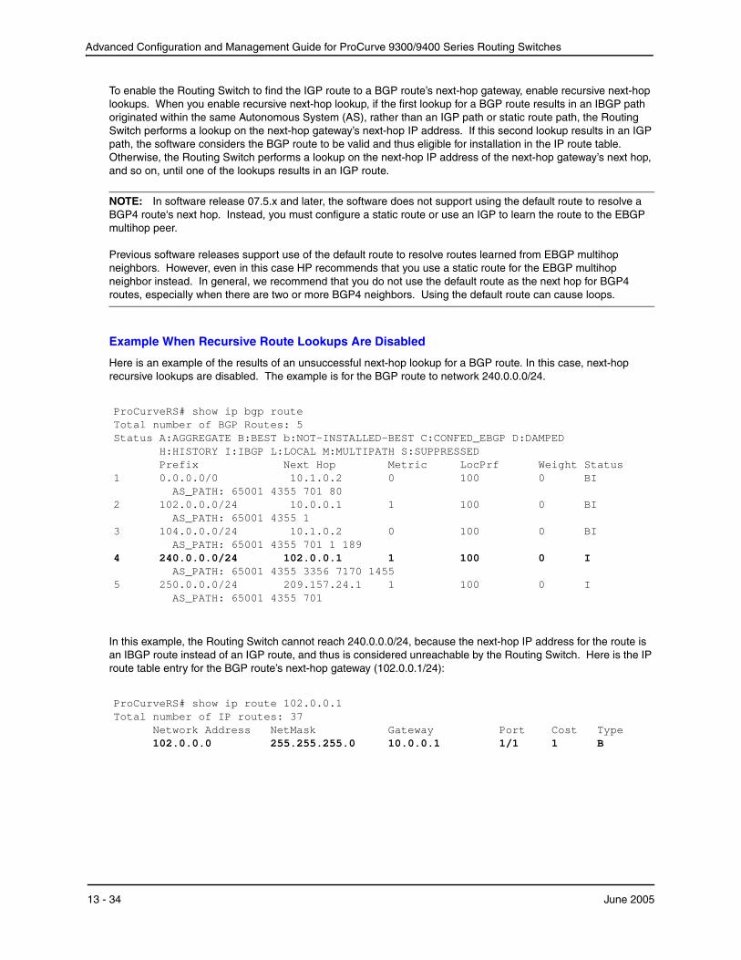
Advanced Configuration and Management Guide for ProCurve 9300/9400 Series Routing Switches
To enable the Routing Switch to find the IGP route to a BGP route’s next-hop gateway, enable recursive next-hop lookups. When you enable recursive next-hop lookup, if the first lookup for a BGP route results in an IBGP path originated within the same Autonomous System (AS), rather than an IGP path or static route path, the Routing Switch performs a lookup on the next-hop gateway’s next-hop IP address. If this second lookup results in an IGP path, the software considers the BGP route to be valid and thus eligible for installation in the IP route table. Otherwise, the Routing Switch performs a lookup on the next-hop IP address of the next-hop gateway’s next hop, and so on, until one of the lookups results in an IGP route.
NOTE: In software release 07.5.x and later, the software does not support using the default route to resolve a BGP4 route's next hop. Instead, you must configure a static route or use an IGP to learn the route to the EBGP multihop peer.
Previous software releases support use of the default route to resolve routes learned from EBGP multihop neighbors. However, even in this case HP recommends that you use a static route for the EBGP multihop neighbor instead. In general, we recommend that you do not use the default route as the next hop for BGP4 routes, especially when there are two or more BGP4 neighbors. Using the default route can cause loops.
Example When Recursive Route Lookups Are Disabled
Here is an example of the results of an unsuccessful next-hop lookup for a BGP route. In this case, next-hop recursive lookups are disabled. The example is for the BGP route to network 240.0.0.0/24.
ProCurveRS# show ip bgp routeTotal number of BGP Routes: 5Status A:AGGREGATE B:BEST b:NOT-INSTALLED-BEST C:CONFED_EBGP D:DAMPED
H:HISTORY I:IBGP L:LOCAL M:MULTIPATH S:SUPPRESSED
1 Prefix Next Hop 0.0.0.0/0 10.1.0.2
AS_PATH: 65001 4355 701 80
Metric 0
LocPrf 100
Weight Status 0 BI
2 102.0.0.0/24 10.0.0.1 AS_PATH: 65001 4355 1
1 100 0 BI
3
4
104.0.0.0/24 10.1.0.2 0 AS_PATH: 65001 4355 701 1 189 240.0.0.0/24 102.0.0.1 1
AS_PATH: 65001 4355 3356 7170 1455
100
100
0
0
BI
I
5 250.0.0.0/24 209.157.24.1 AS_PATH: 65001 4355 701
1 100 0 I
In this example, the Routing Switch cannot reach 240.0.0.0/24, because the next-hop IP address for the route is an IBGP route instead of an IGP route, and thus is considered unreachable by the Routing Switch. Here is the IP route table entry for the BGP route’s next-hop gateway (102.0.0.1/24):
ProCurveRS# show ip route 102.0.0.1Total number of IP routes: 37
Network Address NetMask Gateway Port Cost Type102.0.0.0 255.255.255.0 10.0.0.1 1/1 1 B
13 - 34 June 2005

Configuring BGP4
The route to the next-hop gateway is a BGP route, not an IGP route, and thus cannot be used to reach 240.0.0.0/ 24. In this case, the Routing Switch tries to use the default route, if present, to reach the sub-net that contains the BGP route’s next-hop gateway.
ProCurveRS# show ip route 240.0.0.0/24Total number of IP routes: 37
Network Address NetMask Gateway Port Cost Type0.0.0.0 0.0.0.0 10.0.0.202 1/1 1 S
Example When Recursive Route Lookups Are Enabled
When recursive next-hop lookups are enabled, the Routing Switch recursively looks up the next-hop gateways along the route until the Routing Switch finds an IGP route to the BGP route’s destination. Here is an example.
ProCurveRS# show ip bgp routeTotal number of BGP Routes: 5Status A:AGGREGATE B:BEST b:NOT-INSTALLED-BEST C:CONFED_EBGP D:DAMPED
H:HISTORY I:IBGP L:LOCAL M:MULTIPATH S:SUPPRESSED
1 Prefix Next Hop
0.0.0.0/0 10.1.0.2 AS_PATH: 65001 4355 701 80
Metric 0
LocPrf 100
Weight Status 0 BI
2 102.0.0.0/24 10.0.0.1 AS_PATH: 65001 4355 1
1 100 0 BI
3
4
104.0.0.0/24 10.1.0.2 0 AS_PATH: 65001 4355 701 1 189 240.0.0.0/24 102.0.0.1 1 AS_PATH: 65001 4355 3356 7170 1455
100
100
0
0
BI
BI
5 250.0.0.0/24 209.157.24.1 AS_PATH: 65001 4355 701
1 100 0 I
The first lookup results in an IBGP route, to network 102.0.0.0/24:
ProCurveRS# show ip route 102.0.0.1Total number of IP routes: 38
Network Address NetMask Gateway Port Cost Type102.0.0.0 255.255.255.0 10.0.0.1 1/1 1 B AS_PATH: 65001 4355 1
Since the route to 102.0.0.1/24 is not an IGP route, the Routing Switch cannot reach the next hop through IP, and thus cannot use the BGP route. In this case, since recursive next-hop lookups are enabled, the Routing Switch next performs a lookup for 102.0.0.1’s next-hop gateway, 10.0.0.1:
ProCurveRS# show ip bgp route 102.0.0.0Number of BGP Routes matching display condition : 1Status A:AGGREGATE B:BEST b:NOT-INSTALLED-BEST C:CONFED_EBGP D:DAMPED
H:HISTORY I:IBGP L:LOCAL M:MULTIPATH S:SUPPRESSED Prefix Next Hop Metric LocPrf Weight Status 102.0.0.0/24 10.0.0.1 1 100 0 BI AS_PATH: 65001 4355 1
1
June 2005 13 - 35
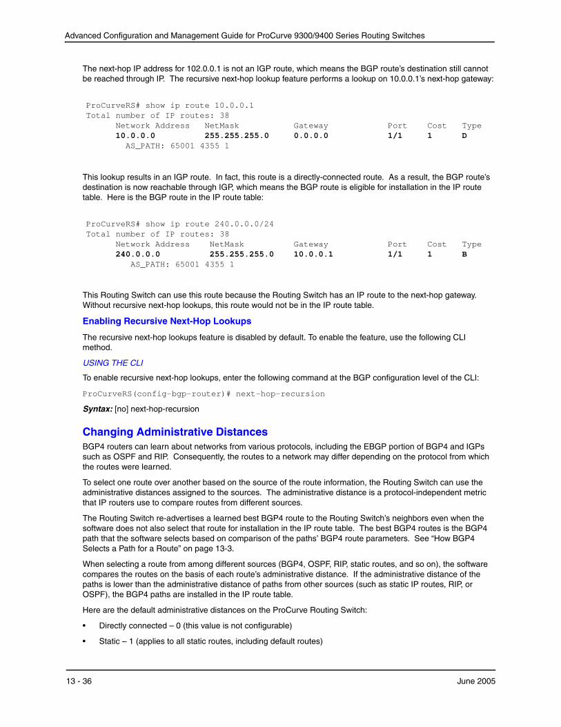
Advanced Configuration and Management Guide for ProCurve 9300/9400 Series Routing Switches
The next-hop IP address for 102.0.0.1 is not an IGP route, which means the BGP route’s destination still cannot be reached through IP. The recursive next-hop lookup feature performs a lookup on 10.0.0.1’s next-hop gateway:
ProCurveRS# show ip route 10.0.0.1Total number of IP routes: 38
Network Address NetMask Gateway Port Cost Type10.0.0.0 255.255.255.0 0.0.0.0 1/1 1 D AS_PATH: 65001 4355 1
This lookup results in an IGP route. In fact, this route is a directly-connected route. As a result, the BGP route’s destination is now reachable through IGP, which means the BGP route is eligible for installation in the IP route table. Here is the BGP route in the IP route table:
ProCurveRS# show ip route 240.0.0.0/24Total number of IP routes: 38
Network Address NetMask Gateway Port Cost Type240.0.0.0 255.255.255.0 10.0.0.1 1/1 1 B AS_PATH: 65001 4355 1
This Routing Switch can use this route because the Routing Switch has an IP route to the next-hop gateway. Without recursive next-hop lookups, this route would not be in the IP route table.
Enabling Recursive Next-Hop Lookups
The recursive next-hop lookups feature is disabled by default. To enable the feature, use the following CLI method.
USING THE CLI
To enable recursive next-hop lookups, enter the following command at the BGP configuration level of the CLI:
ProCurveRS(config-bgp-router)# next-hop-recursion
Syntax: [no] next-hop-recursion
Changing Administrative Distances BGP4 routers can learn about networks from various protocols, including the EBGP portion of BGP4 and IGPs such as OSPF and RIP. Consequently, the routes to a network may differ depending on the protocol from which the routes were learned.
To select one route over another based on the source of the route information, the Routing Switch can use the administrative distances assigned to the sources. The administrative distance is a protocol-independent metric that IP routers use to compare routes from different sources.
The Routing Switch re-advertises a learned best BGP4 route to the Routing Switch’s neighbors even when the software does not also select that route for installation in the IP route table. The best BGP4 routes is the BGP4 path that the software selects based on comparison of the paths’ BGP4 route parameters. See “How BGP4 Selects a Path for a Route” on page 13-3.
When selecting a route from among different sources (BGP4, OSPF, RIP, static routes, and so on), the software compares the routes on the basis of each route’s administrative distance. If the administrative distance of the paths is lower than the administrative distance of paths from other sources (such as static IP routes, RIP, or OSPF), the BGP4 paths are installed in the IP route table.
Here are the default administrative distances on the ProCurve Routing Switch:
• Directly connected – 0 (this value is not configurable)
• Static – 1 (applies to all static routes, including default routes)
13 - 36 June 2005

Configuring BGP4
• EBGP – 20
• OSPF – 110
• RIP – 120
• IBGP – 200
• Local BGP – 200
• Unknown – 255 (the router will not use this route)
Lower administrative distances are preferred over higher distances. For example, if the router receives routes for the same network from OSPF and from RIP, the router will prefer the OSPF route by default. The administrative distances are configured in different places in the software. The Routing Switch re-advertises a learned best BGP4 route to neighbors by default, regardless of whether the route’s administrative distance is lower than other routes from different route sources to the same destination.
• To change the EBGP, IBGP, and Local BGP default administrative distances, see the instructions in this section.
• To change the default administrative distance for OSPF, see “Modify Administrative Distance” on page 12-41.
• To change the default administrative distance for RIP, see “Changing the Administrative Distance” on page 10-6.
• To change the default administrative distance for static routes, see “Configuring Static Routes” on page 9-39.
You can change the default EBGP, IBGP, and Local BGP administrative distances using either of the following methods.
USING THE CLI
To change the default administrative distances for EBGP, IBGP, and Local BGP, enter a command such as the following:
ProCurveRS(config-bgp-router)# distance 180 160 40
Syntax: distance <external-distance> <internal-distance> <local-distance>
The <external-distance> sets the EBGP distance and can be a value from 1 – 255.
The <internal-distance> sets the IBGP distance and can be a value from 1 – 255.
The <local-distance> sets the Local BGP distance and can be a value from 1 – 255.
USING THE WEB MANAGEMENT INTERFACE
1. Log on to the device using a valid user name and password for read-write access. The System configuration panel is displayed.
2. Click on the plus sign next to Configure in the tree view to expand the list of configuration options.
3. Click on the plus sign next to BGP in the tree view to expand the list of BGP option links.
4. Click on the General link to display the BGP configuration panel, shown in Figure 13.2 on page 13-8.
5. Change the number in the External Distance field to change the EBGP distance. You can enter a number from 1 – 255.
6. Change the number in the Internal Distance field to change the IBGP distance. You can enter a number from 1 – 255.
7. Change the number in the Local Distance field to change the local distance. You can enter a number from 1 – 255.
8. Click the Apply button to apply the changes to the device’s running-config file.
9. Select the Save link at the bottom of the dialog. Select Yes when prompted to save the configuration change to the startup-config file on the device’s flash memory.
June 2005 13 - 37

Advanced Configuration and Management Guide for ProCurve 9300/9400 Series Routing Switches
Requiring the First AS to be the Neighbor’s AS By default, the HP device does not require the first AS listed in the AS_SEQUENCE field of an AS path Update from an EBGP neighbor to be the AS that the neighbor who sent the Update is in. You can enable the HP device for this requirement.
When you enable the HP device to require the AS that an EBGP neighbor is in to be the same as the first AS in the AS_SEQUENCE field of an Update from the neighbor, the HP device accepts the Update only if the ASs match. If the ASs do not match, the HP device sends a Notification message to the neighbor and closes the session. The requirement applies to all Updates received from EBGP neighbors.
To enable this feature, enter the following command at the BGP configuration level of the CLI:
ProCurveRS(config-bgp-router)# enforce-first-as
Syntax: [no] enforce-first-as
Disabling or Re-Enabling Comparison of the AS-Path Length AS-Path comparison is Step 5 in the algorithm BGP4 uses to select the next path for a route. Comparison of the AS-Path length is enabled by default. To disable it, enter the following command at the BGP configuration level of the CLI:
ProCurveRS(config-bgp-router)# as-path-ignore
This command disables comparison of the AS-Path lengths of otherwise equal paths. When you disable AS-Path length comparison, the BGP4 algorithm shown in “How BGP4 Selects a Path for a Route” on page 13-3 skips from Step 4 to Step 6.
Syntax: [no] as-path-ignore
Enabling or Disabling Comparison of the Router IDs Router ID comparison is Step 10 in the algorithm BGP4 uses to select the next path for a route.
NOTE: Comparison of router IDs is applicable only when BGP4 load sharing is disabled.
When router ID comparison is enabled, the path comparison algorithm compares the router IDs of the neighbors that sent the otherwise equal paths.
• If BGP4 load sharing is disabled (maximum-paths 1), the Routing Switch selects the path that came from the neighbor with the lower router ID.
• If BGP4 load sharing is enabled, the Routing Switch load shares among the remaining paths. In this case, the router ID is not used to select a path.
NOTE: Router ID comparison is disabled by default in software release 07.5.04. In previous releases, router ID comparison is enabled by default and cannot be disabled.
To enable router ID comparison, enter the following command at the BGP configuration level of the CLI:
ProCurveRS(config-bgp-router)# compare-routerid
Syntax: [no] compare-routerid
For more information, see “How BGP4 Selects a Path for a Route” on page 13-3.
Configuring the Routing Switch To Always Compare Multi-Exit Discriminators (MEDs) A Multi-Exit Discriminator (MED) is a value that the BGP4 algorithm uses when comparing multiple paths received from different BGP4 neighbors in the same AS for the same route. In BGP4, a route’s MED is equivalent to its “metric”.
13 - 38 June 2005

Configuring BGP4
• Beginning in software release 07.5.04, BGP4 compares the MEDs of two otherwise equivalent paths if and only if the routes were learned from the same neighboring AS. This behavior is called deterministic MED. In software release 07.5.04 and later, deterministic MED is always enabled and cannot be disabled.
In addition, you can enable the Routing Switch to always compare the MEDs, regardless of the AS information in the paths. To enable this comparison, enter the always-compare-med command at the BGP4 configuration level of the CLI. This option is disabled by default.
• Before software release 07.5.04, the Routing Switch compares the MEDs based on one or more of the following conditions. By default, the Routing Switch compares the MEDs of paths only if the first AS in the paths is the same. (The Routing Switch skips over the AS-CONFED-SEQUENCE if present.)
You can enable the Routing Switch to always compare the MEDs, regardless of the AS information in the paths. For example, if the router receives UPDATES for the same route from neighbors in three ASs, the router would compare the MEDs of all the paths together, rather than comparing the MEDs for the paths in each AS individually.
NOTE: By default, value 0 (most favorable) is used in MED comparison when the MED attribute is not present. The default MED comparison results in the Routing Switch favoring the route paths that are missing their MEDs. In software release 07.5.04 and later, you can use the med-missing-as-worst command to make the Routing Switch regard a BGP route with a missing MED attribute as the least favorable route, when comparing the MEDs of the routes.
NOTE: MED comparison is not performed for internal routes originated within the local AS or confederation.
To configure the router to always compare MEDs for all paths for a route, use either of the following methods:
USING THE CLI
To configure the router to always compare MEDs, enter the following command:
ProCurveRS(config-bgp-router)# always-compare-med
Syntax: [no] always-compare-med
USING THE WEB MANAGEMENT INTERFACE
1. Log on to the device using a valid user name and password for read-write access. The System configuration panel is displayed.
2. Click on the plus sign next to Configure in the tree view to expand the list of configuration options.
3. Click on the plus sign next to BGP in the tree view to expand the list of BGP option links.
4. Click on the General link to display the BGP configuration panel, shown in Figure 13.2 on page 13-8.
5. Select Disable or Enable next to Always Compare MED.
6. Click the Apply button to apply the changes to the device’s running-config file.
7. Select the Save link at the bottom of the dialog. Select Yes when prompted to save the configuration change to the startup-config file on the device’s flash memory.
Treating Missing MEDs as the Worst MEDs By default, the Routing Switch favors a lower MED over a higher MED during MED comparison. Since the Routing Switch assigns the value 0 to a route path’s MED if the MED value is missing, the default MED comparison results in the Routing Switch favoring the route paths that are missing their MEDs.
USING THE CLI
To change this behavior so that the Routing Switch favors a route that has a MED over a route that is missing its MED, enter the following command at the BGP4 configuration level of the CLI:
ProCurveRS(config-bgp-router)# med-missing-as-worst
June 2005 13 - 39
Advanced Configuration and Management Guide for ProCurve 9300/9400 Series Routing Switches
Syntax: [no] med-missing-as-worst
NOTE: This command affects route selection only when route paths are selected based on MED comparison. It is still possible for a route path that is missing its MED to be selected based on other criteria. For example, a route path with no MED can be selected if its weight is larger than the weights of the other route paths.
USING THE WEB MANAGEMENT INTERFACE
You cannot perform this task using the Web management interface.
Automatically Summarizing Subnet Routes Into Class A, B, or C Networks The auto summary feature summarizes the routes it redistributes from IGP to BGP4. The router summarizes subnets into their natural class A, B, or C networks. For example, if an AS contains sub-nets 1.1.0.0, 1.2.0.0, and 1.3.0.0 with the network mask 255.255.0.0, the auto summary feature summarizes the sub-nets in its advertisements to BGP4 neighbors as 1.0.0.0/8.
The auto summary feature is disabled by default. If you want to enable the feature, use either of the following methods.
NOTE: The auto summary feature summarizes only the routes that are redistributed from IGP into BGP4.
NOTE: The auto summary feature does not summarize networks that use CIDR numbers instead of class A, B, or C numbers. To summarize CIDR networks, use the aggregation feature. See “Aggregating Routes Advertised to BGP4 Neighbors” on page 13-46.
USING THE CLI
To enable auto summary, enter the following command:
ProCurveRS(config-bgp-router)# auto-summary
To disable auto summary again, enter the following command:
ProCurveRS(config-bgp-router)# no auto-summary
Syntax: [no] auto-summary
USING THE WEB MANAGEMENT INTERFACE
1. Log on to the device using a valid user name and password for read-write access. The System configuration panel is displayed.
2. Click on the plus sign next to Configure in the tree view to expand the list of configuration options.
3. Click on the plus sign next to BGP in the tree view to expand the list of BGP option links.
4. Click on the General link to display the BGP configuration panel, shown in Figure 13.2 on page 13-8.
5. Select Disable or Enable next to Auto Summary.
6. Click the Apply button to apply the changes to the device’s running-config file.
7. Select the Save link at the bottom of the dialog. Select Yes when prompted to save the configuration change to the startup-config file on the device’s flash memory.
Configuring Route Reflection Parameters Normally, all the BGP routers within an AS are fully meshed. Each of the routers has an IBGP session with each of the other BGP routers in the AS. Each IBGP router thus has a route for each of its IBGP neighbors. For large ASs containing many IBGP routers, the IBGP route information in each of the fully-meshed IBGP routers can introduce too much administrative overhead.
To avoid this problem, you can hierarchically organize your IGP routers into clusters.
• A cluster is a group of IGP routers organized into route reflectors and route reflector clients. You configure
13 - 40 June 2005
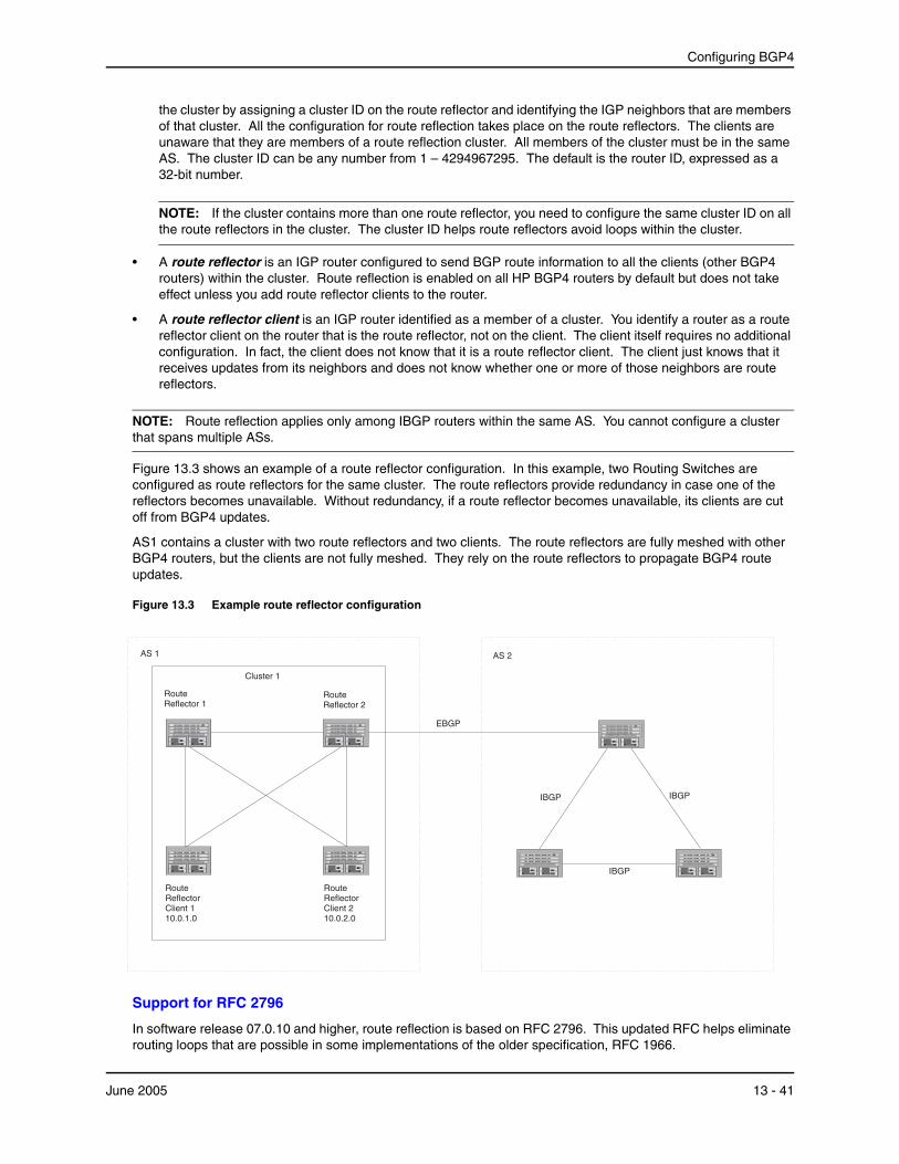
Configuring BGP4
the cluster by assigning a cluster ID on the route reflector and identifying the IGP neighbors that are members of that cluster. All the configuration for route reflection takes place on the route reflectors. The clients are unaware that they are members of a route reflection cluster. All members of the cluster must be in the same AS. The cluster ID can be any number from 1 – 4294967295. The default is the router ID, expressed as a 32-bit number.
NOTE: If the cluster contains more than one route reflector, you need to configure the same cluster ID on all the route reflectors in the cluster. The cluster ID helps route reflectors avoid loops within the cluster.
• A route reflector is an IGP router configured to send BGP route information to all the clients (other BGP4 routers) within the cluster. Route reflection is enabled on all HP BGP4 routers by default but does not take effect unless you add route reflector clients to the router.
• A route reflector client is an IGP router identified as a member of a cluster. You identify a router as a route reflector client on the router that is the route reflector, not on the client. The client itself requires no additional configuration. In fact, the client does not know that it is a route reflector client. The client just knows that it receives updates from its neighbors and does not know whether one or more of those neighbors are route reflectors.
NOTE: Route reflection applies only among IBGP routers within the same AS. You cannot configure a cluster that spans multiple ASs.
Figure 13.3 shows an example of a route reflector configuration. In this example, two Routing Switches are configured as route reflectors for the same cluster. The route reflectors provide redundancy in case one of the reflectors becomes unavailable. Without redundancy, if a route reflector becomes unavailable, its clients are cut off from BGP4 updates.
AS1 contains a cluster with two route reflectors and two clients. The route reflectors are fully meshed with other BGP4 routers, but the clients are not fully meshed. They rely on the route reflectors to propagate BGP4 route updates.
Figure 13.3 Example route reflector configuration
EBGP
IBGP
IBGP
AS 2
Route Reflector 2
IBGP
Cluster 1
Route Reflector Client 2 10.0.2.0
Route Reflector 1
Route Reflector Client 1 10.0.1.0
AS 1
Support for RFC 2796
In software release 07.0.10 and higher, route reflection is based on RFC 2796. This updated RFC helps eliminate routing loops that are possible in some implementations of the older specification, RFC 1966.
June 2005 13 - 41

Advanced Configuration and Management Guide for ProCurve 9300/9400 Series Routing Switches
NOTE: The configuration procedure for route reflection is the same regardless of whether your software release is using RFC 1966 or RFC 2796. However, the operation of the feature is different as explained below.
RFC 2796 provides more details than RFC 1966 regarding the use of the route reflection attributes, ORIGINATOR_ID and CLUSTER_LIST, to help prevent loops.
• ORIGINATOR_ID – Specifies the router ID of the BGP4 router that originated the route. The route reflector inserts this attribute when reflecting a route to an IBGP neighbor. If a BGP4 router receives an advertisement that contains its own router ID as the ORIGINATOR_ID, the router discards the advertisement and does not forward it.
• CLUSTER_LIST – A list of the route reflection clusters through which the advertisement has passed. A cluster contains a route reflector and its clients. When a route reflector reflects a route, the route reflector adds its cluster ID to the front of the CLUSTER_LIST. If a route reflector receives a route that has its own cluster ID, the router discards the advertisement and does not forward it.
Software release 07.0.10 and higher handles the attributes as follows:
• The Routing Switch adds the attributes only if it is a route reflector, and only when advertising IBGP route information to other IBGP neighbors. The attributes are not used when communicating with EBGP neighbors.
• A Routing Switch configured as a route reflector sets the ORIGINATOR_ID attribute to the router ID of the router that originated the route. Moreover, the route reflector sets the attribute only if this is the first time the route is being reflected (sent by a route reflector). In previous software releases, the route reflector set the attribute to the router ID of the route reflector itself. When a Routing Switch receives a route that already has the ORIGINATOR_ID attribute set, the Routing Switch does not change the value of the attribute.
• If a Routing Switch receives a route whose ORIGINATOR_ID attribute has the value of the Routing Switch’s own router ID, the Routing Switch discards the route and does not advertise it. By discarding the route, the Routing Switch prevents a routing loop. The Routing Switch did not discard the route in previous software releases.
• The first time a route is reflected by a Routing Switch configured as a route reflector, the route reflector adds the CLUSTER_LIST attribute to the route. Other route reflectors who receive the route from an IBGP neighbor add their cluster IDs to the front of the route’s CLUSTER_LIST. If the route reflector does not have a cluster ID configured, the Routing Switch adds its router ID to the front of the CLUSTER_LIST.
• If Routing Switch configured as a route reflector receives a route whose CLUSTER_LIST contains the route reflector’s own cluster ID, the route reflector discards the route and does not forward it.
Configuration Procedures
To configure a ProCurve Routing Switch to be a BGP4 route reflector, use either of the following methods.
NOTE: All configuration for route reflection takes place on the route reflectors, not on the clients.
USING THE CLI
Enter the following commands to configure a ProCurve Routing Switch as route reflector 1 in Figure 13.3 on page 13-41. To configure route reflector 2, enter the same commands on the ProCurve Routing Switch that will be route reflector 2. The clients require no configuration for route reflection.
ProCurveRS(config-bgp-router)# cluster-id 1 ProCurveRS(config-bgp-router)# neighbor 10.0.1.0 route-reflector-client ProCurveRS(config-bgp-router)# neighbor 10.0.2.0 route-reflector-client
Syntax: [no] cluster-id <num> | <ip-addr>
The <num> | <ip-addr> parameter specifies the cluster ID and can be a number from 1 – 4294967295 or an IP address. The default is the router ID. You can configure one cluster ID on the router. All route-reflector clients for the router are members of the cluster.
13 - 42 June 2005

Configuring BGP4
NOTE: If the cluster contains more than one route reflector, you need to configure the same cluster ID on all the route reflectors in the cluster. The cluster ID helps route reflectors avoid loops within the cluster.
To add an IBGP neighbor to the cluster, enter the following command:
Syntax: neighbor <ip-addr> route-reflector-client
For more information about the neighbor command, see “Adding BGP4 Neighbors” on page 13-13.
By default, the clients of a route reflector are not required to be fully meshed; the routes from a client are reflected to other clients. However, if the clients are fully meshed, route reflection is not required between clients.
If you need to disable route reflection between clients, enter the following command. When the feature is disabled, route reflection does not occur between clients but reflection does still occur between clients and nonclients.
ProCurveRS(config-bgp-router)# no client-to-client-reflection
Enter the following command to re-enable the feature:
ProCurveRS(config-bgp-router)# client-to-client-reflection
Syntax: [no] client-to-client-reflection
USING THE WEB MANAGEMENT INTERFACE
1. Log on to the device using a valid user name and password for read-write access. The System configuration panel is displayed.
2. Click on the plus sign next to Configure in the tree view to expand the list of configuration options.
3. Click on the plus sign next to BGP in the tree view to expand the list of BGP option links.
4. Click on the General link to display the BGP configuration panel, shown in Figure 13.2 on page 13-8.
5. If route reflection is not already enabled, select Enable next to Client To Client Reflection.
6. If the autonomous system (AS) the Routing Switch is in will contain more than one route reflector (a route reflector in addition to the Routing Switch), enter a cluster ID in the Cluster ID field. The cluster ID is required to avoid loops in an AS that contains more than one route reflector.
7. Click the Apply button to apply the changes to the device’s running-config file.
8. Click on the Neighbor link at the bottom of the BGP configuration panel or under BGP in the Configure section of the tree view.
9. If you have already configured neighbors, a table listing the neighbors is displayed. Click Modify next to the neighbor you want to identify as a route reflector client or select the Add Neighbor link. The BGP configuration panel is displayed.
10. Configure or change other parameters if needed, then identify this neighbor as a route reflector client by selecting Enable next to Client To Client Reflection. See “Adding BGP4 Neighbors” on page 13-13 for information about the other neighbor parameters.
11. Click the Add button to apply the changes to the device’s running-config file.
12. Select the Save link at the bottom of the dialog. Select Yes when prompted to save the configuration change to the startup-config file on the device’s flash memory.
Configuring Confederations A confederation is a BGP4 Autonomous System (AS) that has been subdivided into multiple, smaller ASs. Subdividing an AS into smaller ASs simplifies administration and reduces BGP-related traffic, thus reducing the complexity of the Interior Border Gateway Protocol (IBGP) mesh among the BGP routers in the AS.
The HP implementation of this feature is based on RFC 3065.
June 2005 13 - 43

Advanced Configuration and Management Guide for ProCurve 9300/9400 Series Routing Switches
Normally, all BGP routers within an AS must be fully meshed, so that each BGP router has interfaces to all the other BGP routers within the AS. This is feasible in smaller ASs but becomes unmanageable in ASs containing many BGP routers.
When you configure BGP routers into a confederation, all the routers within a sub-AS (a subdivision of the AS) use IBGP and must be fully meshed. However, routers use EBGP to communicate between different sub-ASs.
NOTE: Another method for reducing the complexity of an IBGP mesh is to use route reflection. However, if you want to run different Interior Gateway Protocols (IGPs) within an AS, configure a confederation. You can run a separate IGP within each sub-AS.
To configure a confederation, configure groups of BGP routers into sub-ASs. A sub-AS is simply an AS. The term “sub-AS” distinguishes ASs within a confederation from ASs that are not in a confederation. For the viewpoint of remote ASs, the confederation ID is the AS ID. Remote ASs do not know that the AS represents multiple sub-ASs with unique AS IDs.
NOTE: You can use any valid AS numbers for the sub-ASs. If your AS is connected to the Internet, HP recommends that you use numbers from within the private AS range (64512 – 65535). These are private ASs numbers and BGP4 routers do not propagate these AS numbers to the Internet.
Figure 13.4 shows an example of a BGP4 confederation.
Figure 13.4 Example BGP4 confederation
IBGP
Sub-AS 64513
Router D
AS 20
Router C
This BGP4 router sees all
are subdivided into sub-ASs within a
Sub-AS 64512
Router BRouter A
IBGP
EBGP
EBGP
traffic from Confederation 10 as traffic from AS 10.
Routers outside the confederation do not know or care that the routers
confederation.
Confederation 10
In this example, four routers are configured into two sub-ASs, each containing two of the routers. The sub-ASs are members of confederation 10. Routers within a sub-AS must be fully meshed and communicate using IBGP. In this example, routers A and B use IBGP to communicate. Routers C and D also use IBGP. However, the sub-ASs communicate with one another using EBGP. For example, router A communicates with router C using EBGP. The routers in the confederation communicate with other ASs using EBGP.
13 - 44 June 2005
Configuring BGP4
Routers in other ASs are unaware that routers A – D are configured in a confederation. In fact, when routers in confederation 10 send traffic to routers in other ASs, the confederation ID is the same as the AS number for the routers in the confederation. Thus, routers in other ASs see traffic from AS 10 and are unaware that the routers in AS 10 are subdivided into sub-ASs within a confederation.
Configuring a BGP Confederation
Perform the following configuration tasks on each BGP router within the confederation:
• Configure the local AS number. The local AS number indicates membership in a sub-AS. All BGP routers with the same local AS number are members of the same sub-AS. BGP routers use the local AS number when communicating with other BGP routers within the confederation.
• Configure the confederation ID. The confederation ID is the AS number by which BGP routers outside the confederation know the confederation. Thus, a BGP router outside the confederation is not aware and does not care that your BGP routers are in multiple sub-ASs. BGP routers use the confederation ID when communicating with routers outside the confederation. The confederation ID must be different from the sub-AS numbers.
• Configure the list of the sub-AS numbers that are members of the confederation. All the routers within the same sub-AS use IBGP to exchange router information. Routers in different sub-ASs within the confederation use EBGP to exchange router information.
To configure a Routing Switch to be a member of a BGP confederation, use one of the following methods. The procedures show how to implement the example confederation shown in Figure 13.4.
USING THE CLI
To configure four Routing Switches to be a member of confederation 10, consisting of two sub-ASs (64512 and 64513), enter commands such as the following.
Commands for Router A ProCurveRSA(config)# router bgp ProCurveRSA(config-bgp-router)# local-as 64512 ProCurveRSA(config-bgp-router)# confederation identifier 10 ProCurveRSA(config-bgp-router)# confederation peers 64512 64513 ProCurveRSA(config-bgp-router)# write memory
Syntax: local-as <num>
The <num> parameter with the local-as command indicates the AS number for the BGP routers within the sub-AS. You can specify a number from 1 – 65535. HP recommends that you use a number within the range of wellknown private ASs, 64512 – 65535.
Syntax: confederation identifier <num>
The <num> parameter with the confederation identifier command indicates the confederation number. The confederation ID is the AS number by which BGP routers outside the confederation know the confederation. Thus, a BGP router outside the confederation is not aware and does not care that your BGP routers are in multiple sub-ASs. BGP routers use the confederation ID when communicating with routers outside the confederation. The confederation ID must be different from the sub-AS numbers. You can specify a number from 1 – 65535.
Syntax: confederation peers <num> [<num> …]
The <num> parameter with the confederation peers command indicates the sub-AS numbers for the sub-ASs in the confederation. You must specify all the sub-ASs contained in the confederation. All the routers within the same sub-AS use IBGP to exchange router information. Routers in different sub-ASs within the confederation use EBGP to exchange router information. You can specify a number from 1 – 65535.
Commands for Router B ProCurveRSB(config)# router bgp ProCurveRSB(config-bgp-router)# local-as 64512 ProCurveRSB(config-bgp-router)# confederation identifier 10 ProCurveRSB(config-bgp-router)# confederation peers 64512 64513 ProCurveRSB(config-bgp-router)# write memory
June 2005 13 - 45

Advanced Configuration and Management Guide for ProCurve 9300/9400 Series Routing Switches
Commands for Router C ProCurveRSC(config)# router bgp ProCurveRSC(config-bgp-router)# local-as 64513 ProCurveRSC(config-bgp-router)# confederation identifier 10 ProCurveRSC(config-bgp-router)# confederation peers 64512 64513 ProCurveRSC(config-bgp-router)# write memory
Commands for Router D ProCurveRSD(config)# router bgp ProCurveRSD(config-bgp-router)# local-as 64513 ProCurveRSD(config-bgp-router)# confederation identifier 10 ProCurveRSD(config-bgp-router)# confederation peers 64512 64513 ProCurveRSD(config-bgp-router)# write memory
USING THE WEB MANAGEMENT INTERFACE
1. Log on to the device using a valid user name and password for read-write access. The System configuration panel is displayed.
2. Click on the plus sign next to Configure in the tree view to expand the list of configuration options.
3. Click on the plus sign next to BGP in the tree view to expand the list of BGP option links.
4. Click on the General link to display the BGP configuration panel, shown in Figure 13.2 on page 13-8.
5. Enter the confederation ID in the Confederation ID field. The confederation ID must be different from the sub-AS numbers. You can specify a number from 1 – 65535.
6. Enter the AS numbers of the peers (sub-ASs) within the confederation in the Confederation Peers field. Separate the AS numbers with spaces. You must specify all the sub-ASs contained in the confederation. All the routers within the same sub-AS use IBGP to exchange router information. Routers in different sub-ASs within the confederation use EBGP to exchange router information. You can specify a number from 1 – 65535.
7. Click the Apply button to apply the changes to the device’s running-config file.
8. Select the Save link at the bottom of the dialog, then select Yes when prompted to save the configuration change to the startup-config file on the device’s flash memory.
Aggregating Routes Advertised to BGP4 Neighbors By default, the Routing Switch advertises individual routes for all the networks. The aggregation feature allows you to configure the Routing Switch to aggregate routes in a range of networks into a single CIDR number. For example, without aggregation, the Routing Switch will individually advertise routes for networks 207.95.1.0, 207.95.2.0, and 207.95.3.0. You can configure the Routing Switch to instead send a single, aggregate route for the networks. The aggregate route would be advertised as 207.95.0.0.
NOTE: To summarize CIDR networks, you must use the aggregation feature. The auto summary feature does not summarize networks that use CIDR numbers instead of class A, B, or C numbers.
To aggregate routes, use either of the following methods.
USING THE CLI
To aggregate routes for 209.157.22.0, 209.157.23.0, and 209.157.24.0, enter the following command:
ProCurveRS(config-bgp-router)# aggregate-address 209.157.0.0 255.255.0.0
Syntax: aggregate-address <ip-addr> <ip-mask> [as-set] [nlri multicast | unicast | multicast unicast] [summary-only] [suppress-map <map-name>] [advertise-map <map-name>] [attribute-map <map-name>]
The <ip-addr> and <ip-mask> parameters specify the aggregate value for the networks. Specify 0 for the host portion and for the network portion that differs among the networks in the aggregate. For example, to aggregate 10.0.1.0, 10.0.2.0, and 10.0.3.0, enter the IP address 10.0.0.0 and the network mask 255.255.0.0.
13 - 46 June 2005

Configuring BGP4
The as-set parameter causes the router to aggregate AS-path information for all the routes in the aggregate address into a single AS-path.
The nlri multicast | unicast | multicast unicast parameter specifies whether the neighbor is a multicast neighbor or a unicast neighbor. For MBGP, you must specify multicast. Optionally, you also can specify unicast if you want the Routing Switch to exchange unicast (BGP4) routes as well as multicast routes with the neighbor. The default is unicast only. For more information, see “Configuring MBGP (9300 Series Only)” on page 14-1.
The summary-only parameter prevents the router from advertising more specific routes contained within the aggregate route.
The suppress-map <map-name> parameter prevents the more specific routes contained in the specified route map from being advertised.
The advertise-map <map-name> parameter configures the router to advertise the more specific routes in the specified route map.
The attribute-map <map-name> parameter configures the router to set attributes for the aggregate routes based on the specified route map.
NOTE: For the suppress-map, advertise-map, and attribute-map parameters, the route map must already be defined. See “Defining Route Maps” on page 13-68 for information on defining a route map.
USING THE WEB MANAGEMENT INTERFACE
1. Log on to the device using a valid user name and password for read-write access. The System configuration panel is displayed.
2. Click on the plus sign next to Configure in the tree view to expand the list of configuration options.
3. Click on the plus sign next to BGP in the tree view to expand the list of BGP option links.
4. Click on the Aggregate Address link to display the BGP Aggregate Address configuration panel.
• If the device does not have any BGP aggregate addresses configured, the BGP Aggregate Address configuration panel is displayed, as shown in the following example.
• If a BGP aggregate address is already configured and you are adding a new one, click on the Add Aggregate Address link to display the BGP Aggregate Address configuration panel, as shown in the following example.
• If you are modifying an existing BGP aggregate address, click on the Modify button to the right of the row describing the aggregate address to display the BGP Aggregate Address configuration panel, as shown in the following example.
5. Enter the aggregate address in the IP Address field. Specify 0 for the host portion and for the network portion that differs among the networks in the aggregate. For example, to aggregate 10.0.1.0, 10.0.2.0, and 10.0.3.0, enter the IP address 10.0.0.0. Then enter 255.255.0.0 in the Mask field.
June 2005 13 - 47

Advanced Configuration and Management Guide for ProCurve 9300/9400 Series Routing Switches
6. Enter the mask in the Mask field.
7. Select one of the following options from the Option field’s pulldown list:
• Address – Use this option when you are adding the address. This is the default option.
• AS Set – This option causes the router to aggregate AS-path information for all the routes in the aggregate address into a single AS-path.
• Summary Only – This option prevents the router from advertising more specific routes contained within the aggregate route.
• Suppress Map – This option prevents the more specific routes contained in the specified route map from being advertised.
• Advertise Map – This option configures the router to advertise the more specific routes in the specified route map.
• Attribute Map – This option configures the router to set attributes for the aggregate routes based on the specified route map.
8. Optionally select a route map from the Map field’s pulldown list.
NOTE: For the Suppress Map, Advertise Map, and Attribute Map options, you must select a route map and the route map must already be defined. See “Defining Route Maps” on page 13-68 for information on defining a route map.
9. Click the Add button to apply the changes to the device’s running-config file.
10. Select the Save link at the bottom of the dialog. Select Yes when prompted to save the configuration change to the startup-config file on the device’s flash memory.
Modifying Redistribution Parameters By default, the router does not redistribute route information between BGP4 and the IP IGPs (RIP and OSPF). You can configure the router to redistribute OSPF routes, RIP routes, directly connected routes, or static routes into BGP4 by using the following methods.
USING THE CLI
To enable redistribution of all OSPF routes and directly attached routes into BGP4, enter the following commands.
ProCurveRS(config)# router bgpProCurveRS(config-bgp-router)# redistribute ospfProCurveRS(config-bgp-router)# redistribute connectedProCurveRS(config-bgp-router)# write memory
Syntax: [no] redistribute connected | ospf | rip | static
The connected parameter indicates that you are redistributing routes to directly attached devices into BGP.
The ospf parameter indicates that you are redistributing OSPF routes into BGP4.
NOTE: Entering redistribute ospf simply redistributes internal OSPF routes. If you want to redistribute external OSPF routes also, you must use the redistribute ospf match external... command. See “Redistributing OSPF External Routes” on page 13-50.
The rip parameter indicates that you are redistributing RIP routes into BGP4.
The static parameter indicates that you are redistributing static routes into BGP.
See the following sections for details on redistributing specific routes using the CLI:
• “Redistributing Connected Routes” on page 13-50
• “Redistributing RIP Routes” on page 13-50
13 - 48 June 2005

Configuring BGP4
• “Redistributing OSPF External Routes” on page 13-50
• “Redistributing Static Routes” on page 13-51
USING THE WEB MANAGEMENT INTERFACE
The following procedure applies to redistributing RIP, OSPF, static, and connected (directly attached) routes.
1. Log on to the device using a valid user name and password for read-write access. The System configuration panel is displayed.
2. Click on the plus sign next to Configure in the tree view to expand the list of configuration options.
3. Click on the plus sign next to BGP in the tree view to expand the list of BGP option links.
4. Click on the Redistribute link to display the BGP Redistribute configuration panel.
• If the device does not have any BGP redistribution parameters configured, the BGP Redistribute configuration panel is displayed, as shown in the following example.
• If BGP redistribution parameters are already configured and you are adding new ones, click on the Add Redistribute link to display the BGP Redistribute configuration panel, as shown in the following example.
• If you are modifying existing BGP redistribution parameters, click on the Modify button to the right of the row describing the redistribution parameters to display the BGP Redistribute configuration panel, as shown in the following example.
5. Select the source of the routes you want to redistribute into BGP4. You can select RIP, OSPF, Static, or Connected (directly attached) routes.
6. Optionally enter a metric for the redistributed routes in the Metric field. You can specify a value from 0 – 4294967295. The default is 0.
7. Optionally select a route map from the Map field’s pulldown list.
NOTE: The route map must already be defined. See “Defining Route Maps” on page 13-68 for information on defining a route map.
8. Optionally enter a weight for the redistributed routes in the Weight field. You can specify a value from 0 – 65535. The default is 0.
9. For OSPF routes, select one of the following to specify the types of OSPF routes to be redistributed into BGP4:
• Internal
• External 1
• External 2
June 2005 13 - 49

Advanced Configuration and Management Guide for ProCurve 9300/9400 Series Routing Switches
NOTE: If you do not indicate the route type, then OSPF routes will be redistributed internally.
10. Click the Add button to apply the changes to the device’s running-config file.
11. Select the Save link at the bottom of the dialog. Select Yes when prompted to save the configuration change to the startup-config file on the device’s flash memory.
Redistributing Connected Routes To configure BGP4 to redistribute directly connected routes, enter the following command:
ProCurveRS(config-bgp-router)# redistribute connected
Syntax: redistribute connected [metric <num>] [route-map <map-name>]
The connected parameter indicates that you are redistributing routes to directly attached devices into BGP4.
The metric <num> parameter changes the metric. You can specify a value from 0 – 4294967295. The default is 0.
The route-map <map-name> parameter specifies a route map to be consulted before adding the RIP route to the BGP4 route table.
NOTE: The route map you specify must already be configured on the router. See “Defining Route Maps” on page 13-68 for information about defining route maps.
Redistributing RIP Routes USING THE CLI
To configure BGP4 to redistribute RIP routes and add a metric of 10 to the redistributed routes, enter the following command:
ProCurveRS(config-bgp-router)# redistribute rip metric 10
Syntax: redistribute rip [metric <num>] [route-map <map-name>]
The rip parameter indicates that you are redistributing RIP routes into BGP4.
The metric <num> parameter changes the metric. You can specify a value from 0 – 4294967295. The default is 0.
The route-map <map-name> parameter specifies a route map to be consulted before adding the RIP route to the BGP4 route table.
NOTE: The route map you specify must already be configured on the router. See “Defining Route Maps” on page 13-68 for information about defining route maps.
Redistributing OSPF External Routes To configure the Routing Switch to redistribute OSPF external type 1 routes, enter the following command:
ProCurveRS(config-bgp-router)# redistribute ospf match external1
Syntax: redistribute ospf [match internal | external1 | external2] [metric <num>] [route-map <map-name>]
The ospf parameter indicates that you are redistributing OSPF routes into BGP4.
The match internal | external1 | external2 parameter applies only to OSPF. This parameter specifies the types of OSPF routes to be redistributed into BGP4. The default is internal.
NOTE: If you do not enter a value for the match parameter, (for example, you enter redistribute ospf only) then only internal OSPF routes will be redistributed.
13 - 50 June 2005

Configuring BGP4
The metric <num> parameter changes the metric. You can specify a value from 0 – 4294967295. The default is 0.
The route-map <map-name> parameter specifies a route map to be consulted before adding the OSPF route to the BGP4 route table.
NOTE: The route map you specify must already be configured on the router. See “Defining Route Maps” on page 13-68 for information about defining route maps.
NOTE: If you use both the redistribute ospf route-map <map-name> command and the redistribute ospf match internal | external1 | external2 command, the software uses only the route map for filtering.
Redistributing Static Routes To configure the Routing Switch to redistribute static routes, enter the following command:
ProCurveRS(config-bgp-router)# redistribute static
Syntax: redistribute static [metric <num>] [route-map <map-name>]
The static parameter indicates that you are redistributing static routes into BGP4.
The metric <num> parameter changes the metric. You can specify a value from 0 – 4294967295. The default is 0.
The route-map <map-name> parameter specifies a route map to be consulted before adding the static route to the BGP4 route table.
NOTE: The route map you specify must already be configured on the router. See “Defining Route Maps” on page 13-68 for information about defining route maps.
Disabling or Re-Enabling Re-Advertisement of All Learned BGP4 Routes to All BGP4 Neighbors By default, the Routing Switch re-advertises all learned best BGP4 routes to BGP4 neighbors, unless the routes are discarded or blocked by route maps or other filters.
If you want to prevent the Routing Switch from re-advertising a learned best BGP4 route unless that route also is installed in the IP route table, use the following CLI method.
USING THE CLI
To disable re-advertisement of BGP4 routes to BGP4 neighbors except for routes that the software also installs in the route table, enter the following command:
ProCurveRS(config-bgp-router)# no readvertise
Syntax: [no] readvertise
To re-enable re-advertisement, enter the following command:
ProCurveRS(config-bgp-router)# readvertise
USING THE WEB MANAGEMENT INTERFACE
You cannot configure this parameter using the Web management interface.
Redistributing IBGP Routes into RIP and OSPF By default, the Routing Switch does not redistribute IBGP routes from BGP4 into RIP or OSPF. This behavior helps eliminate routing loops. However, if your network can benefit from redistributing the IBGP routes from BGP4 into OSPF or RIP, you can enable the Routing Switch to redistribute the routes. To do so, use the following CLI method.
June 2005 13 - 51
Advanced Configuration and Management Guide for ProCurve 9300/9400 Series Routing Switches
USING THE CLI
To enable the Routing Switch to redistribute BGP4 routes into OSPF and RIP, enter the following command:
ProCurveRS(config-bgp-router)# bgp-redistribute-internal
Syntax: [no] bgp-redistribute-internal
To disable redistribution of IBGP routes into RIP and OSPF, enter the following command:
ProCurveRS(config-bgp-router)# no bgp-redistribute-internal
USING THE WEB MANAGEMENT INTERFACE
You cannot configure this parameter using the Web management interface.
Filtering This section describes the following:
• “Filtering Specific IP Addresses” on page 13-52
• “Filtering AS-Paths” on page 13-54
• “Filtering Communities” on page 13-60
• “Defining IP Prefix Lists” on page 13-63
• “Defining Neighbor Distribute Lists” on page 13-66
• “Defining Route Maps” on page 13-68
• “Using a Table Map To Set the Tag Value” on page 13-80
• “Configuring Cooperative BGP4 Route Filtering” on page 13-80
Filtering Specific IP Addresses You can configure the router to explicitly permit or deny specific IP addresses received in updates from BGP4 neighbors by defining IP address filters. The router permits all IP addresses by default. You can define up to 100 IP address filters for BGP4.
• If you want permit to remain the default behavior, define individual filters to deny specific IP addresses.
• If you want to change the default behavior to deny, define individual filters to permit specific IP addresses.
NOTE: Once you define a filter, the default action for addresses that do not match a filter is “deny”. To change the default action to “permit”, configure the last filter as “permit any any”.
Address filters can be referred to by a BGP neighbor's distribute list number as well as by match statements in a route map.
NOTE: If the filter is referred to by a route map’s match statement, the filter is applied in the order in which the filter is listed in the match statement.
NOTE: You also can filter on IP addresses by using IP ACLs. See “Software-Based IP Access Control Lists (ACLs)”.
To define an IP address filter, use either of the following methods.
USING THE CLI
To define an IP address filter to deny routes to 209.157.0.0, enter the following command:
ProCurveRS(config-bgp-router)# address-filter 1 deny 209.157.0.0 255.255.0.0
Syntax: address-filter <num> permit | deny <ip-addr> <wildcard> <mask> <wildcard>
13 - 52 June 2005
Configuring BGP4
The <num> parameter is the filter number.
The permit | deny parameter indicates the action the Routing Switch takes if the filter match is true.
• If you specify permit, the Routing Switch permits the route into the BGP4 table if the filter match is true.
• If you specify deny, the Routing Switch denies the route from entering the BGP4 table if the filter match is true.
NOTE: Once you define a filter, the default action for addresses that do not match a filter is “deny”. To change the default action to “permit”, configure the last filter as “permit any any”.
The <ip-addr> parameter specifies the IP address. If you want the filter to match on all addresses, enter any.
The <wildcard> parameter specifies the portion of the IP address to match against. The <wildcard> is a four-part value in dotted-decimal notation (IP address format) consisting of ones and zeros. Zeros in the mask mean the packet’s source address must match the <source-ip>. Ones mean any value matches. For example, the <ip-addr> and <wildcard> values 209.157.22.26 0.0.0.255 mean that all hosts in the Class C sub-net 209.157.22.x match the policy.
If you prefer to specify the wildcard (mask value) in Classless Interdomain Routing (CIDR) format, you can enter a forward slash after the IP address, then enter the number of significant bits in the mask. For example, you can enter the CIDR equivalent of “209.157.22.26 0.0.0.255” as “209.157.22.26/24”. The CLI automatically converts the CIDR number into the appropriate mask (where zeros instead of ones are the significant bits) and changes the non-significant portion of the IP address into zeros. For example, if you specify 209.157.22.26/24 or 209.157.22.26 0.0.0.255, then save the changes to the startup-config file, the value appears as 209.157.22.0/24 (if you have enabled display of sub-net lengths) or 209.157.22.0 0.0.0.255 in the startup-config file.
If you enable the software to display IP sub-net masks in CIDR format, the mask is saved in the file in “/<maskbits>” format. To enable the software to display the CIDR masks, enter the ip show-subnet-length command at the global CONFIG level of the CLI. You can use the CIDR format to configure the filter regardless of whether the software is configured to display the masks in CIDR format.
The <mask> parameter specifies the network mask. If you want the filter to match on all destination addresses, enter any. The wildcard works the same as described above.
USING THE WEB MANAGEMENT INTERFACE
1. Log on to the device using a valid user name and password for read-write access. The System configuration panel is displayed.
2. Click on the plus sign next to Configure in the tree view to expand the list of configuration options.
3. Click on the plus sign next to BGP in the tree view to expand the list of BGP option links.
4. Click on the Address Filter link to display the BGP Address Filter panel.
• If the device does not have any BGP address filters configured, the BGP Address Filter configuration panel is displayed, as shown in the following example.
• If BGP address filters are already configured and you are adding a new one, click on the Add Address Filter link to display the BGP Address Filter configuration panel, as shown in the following example.
June 2005 13 - 53

Advanced Configuration and Management Guide for ProCurve 9300/9400 Series Routing Switches
• If you are modifying an existing BGP address filter, click on the Modify button to the right of the row describing the filter to display the BGP Address Filter configuration panel, as shown in the following example.
5. Enter the filter ID in the ID field. You can specify a number from 1 – 100.
6. Select the action you want the Routing Switch to perform if the filter is true:
• If you select Deny, the router denies the route from entering the BGP4 table if the filter match is true.
• If you select Permit, the router permits the route into the BGP4 table if the filter match is true.
7. Enter the network prefix in the Prefix field. If you specify “any”, all networks match the filter.
8. Enter the prefix masking bits in the Prefix Masking Bits field. The prefix masking bits indicate the bits in the prefix that the filter compares. The filter disregards the bits for which the mask contains zeros.
9. Enter the mask in the Prefix Mask field. If you specify “any”, all masks match the filter.
10. Enter the masking bits for the network mask in the Prefix Mask Masking Bits field.
11. Click the Add button to apply the changes to the device’s running-config file.
12. Select the Save link at the bottom of the dialog. Select Yes when prompted to save the configuration change to the startup-config file on the device’s flash memory.
Filtering AS-Paths You can filter updates received from BGP4 neighbors based on the contents of the AS-path list accompanying the updates. For example, if you want to deny routes that have the AS 4.3.2.1 in the AS-path from entering the BGP4 route table, you can define a filter to deny such routes.
The Routing Switch provides the following methods for filtering on AS-path information:
• AS-path filters
• AS-path ACLs
NOTE: The Routing Switch cannot actively support AS-path filters and AS-path ACLs at the same time. Use one method or the other but do not mix methods.
NOTE: Once you define a filter or ACL, the default action for updates that do not match a filter is “deny”. To change the default action to “permit”, configure the last filter or ACL as “permit any any”.
AS-path filters or AS-path ACLs can be referred to by a BGP neighbor's filter list number as well as by match statements in a route map.
13 - 54 June 2005
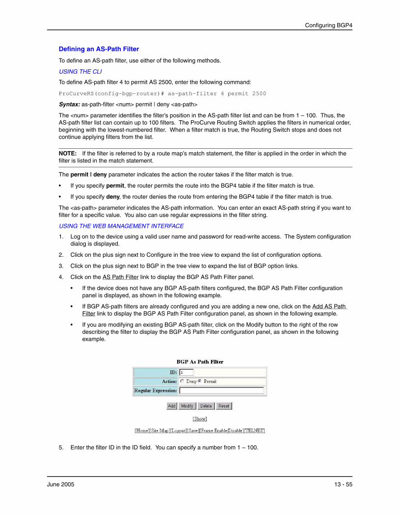
Configuring BGP4
Defining an AS-Path Filter
To define an AS-path filter, use either of the following methods.
USING THE CLI
To define AS-path filter 4 to permit AS 2500, enter the following command:
ProCurveRS(config-bgp-router)# as-path-filter 4 permit 2500
Syntax: as-path-filter <num> permit | deny <as-path>
The <num> parameter identifies the filter’s position in the AS-path filter list and can be from 1 – 100. Thus, the AS-path filter list can contain up to 100 filters. The ProCurve Routing Switch applies the filters in numerical order, beginning with the lowest-numbered filter. When a filter match is true, the Routing Switch stops and does not continue applying filters from the list.
NOTE: If the filter is referred to by a route map’s match statement, the filter is applied in the order in which the filter is listed in the match statement.
The permit | deny parameter indicates the action the router takes if the filter match is true.
• If you specify permit, the router permits the route into the BGP4 table if the filter match is true.
• If you specify deny, the router denies the route from entering the BGP4 table if the filter match is true.
The <as-path> parameter indicates the AS-path information. You can enter an exact AS-path string if you want to filter for a specific value. You also can use regular expressions in the filter string.
USING THE WEB MANAGEMENT INTERFACE
1. Log on to the device using a valid user name and password for read-write access. The System configuration dialog is displayed.
2. Click on the plus sign next to Configure in the tree view to expand the list of configuration options.
3. Click on the plus sign next to BGP in the tree view to expand the list of BGP option links.
4. Click on the AS Path Filter link to display the BGP AS Path Filter panel.
• If the device does not have any BGP AS-path filters configured, the BGP AS Path Filter configuration panel is displayed, as shown in the following example.
• If BGP AS-path filters are already configured and you are adding a new one, click on the Add AS Path Filter link to display the BGP AS Path Filter configuration panel, as shown in the following example.
• If you are modifying an existing BGP AS-path filter, click on the Modify button to the right of the row describing the filter to display the BGP AS Path Filter configuration panel, as shown in the following example.
5. Enter the filter ID in the ID field. You can specify a number from 1 – 100.
June 2005 13 - 55

Advanced Configuration and Management Guide for ProCurve 9300/9400 Series Routing Switches
6. Select the action you want the Routing Switch to perform if the filter is true:
• If you select Deny, the router denies the route from entering the BGP4 table if the filter match is true.
• If you select Permit, the router permits the route into the BGP4 table if the filter match is true.
7. Enter the AS path you want to filter in the Regular Expression field. As indicated by the field’s title, you can use regular expressions for the AS path. See “Using Regular Expressions” on page 13-57.
8. Click the Add button to apply the changes to the device’s running-config file.
9. Select the Save link at the bottom of the dialog. Select Yes when prompted to save the configuration change to the startup-config file on the device’s flash memory.
Defining an AS-Path ACL
To configure an AS-path ACL, use either of the following methods.
USING THE CLI
To configure an AS-path list that uses ACL 1, enter a command such as the following:
ProCurveRS(config)# ip as-path access-list 1 permit 100 ProCurveRS(config)# router bgp ProCurveRS(config-bgp-router)# neighbor 10.10.10.1 filter-list 1 in
The ip as-path command configures an AS-path ACL that permits routes containing AS number 100 in their AS paths. The neighbor command then applies the AS-path ACL to advertisements and updates received from neighbor 10.10.10.1. In this example, the only routes the Routing Switch permits from neighbor 10.10.10.1 are those whose AS-paths contain AS-path number 100.
Syntax: ip as-path access-list <string> [seq <seq-value>] deny | permit <regular-expression>
The <string> parameter specifies the ACL name. (If you enter a number, the CLI interprets the number as a text string.)
The seq <seq-value> parameter is optional and specifies the AS-path list’s sequence number. You can configure up to 199 entries in an AS-path list. If you do not specify a sequence number, the software numbers them in increments of 5, beginning with number 5. The software interprets the entries in an AS-path list in numerical order, beginning with the lowest sequence number.
The deny | permit parameter specifies the action the software takes if a route’s AS-path list matches a match statement in this ACL. To configure the AS-path match statements in a route map, use the match as-path command. See “Matching Based on AS-Path ACL” on page 13-72.
The <regular-expression> parameter specifies the AS path information you want to permit or deny to routes that match any of the match statements within the ACL. You can enter a specific AS number or use a regular expression. For the regular expression syntax, see “Using Regular Expressions” on page 13-57.
The neighbor command uses the filter-list parameter to apply the AS-path ACL to the neighbor. See “Adding BGP4 Neighbors” on page 13-13.
USING THE WEB MANAGEMENT INTERFACE
1. Log on to the device using a valid user name and password for read-write access. The System configuration panel is displayed.
2. Click on the plus sign next to Configure in the tree view to display the list of configuration options.
3. Click on the plus sign next to IP to display the list of IP configuration options.
4. Select the AS Path Access List link.
• If the device does not have any AS Path ACLs, the IP AS Path Access List panel is displayed, as shown in the following example.
• If an AS Path ACL is already configured and you are adding a new one, click on the Add AS Path
13 - 56 June 2005

Configuring BGP4
Access List link to display the IP AS Path Access List panel, as shown in the following example.
NOTE: You cannot modify an AS Path ACL. Instead, you can delete and then re-add the ACL. To delete an ACL, click on the Delete button to the right of the row describing the ACL, then click on the Add AS Path Access List link.
5. Edit the ACL ID in the ID field, if needed. You can enter a number from 1 – 199.
6. Edit the number in the sequence number in the Sequence field, if you want to override the automatically generated sequence number. You can configure up to 199 entries in an AS-path list. If you do not specify a sequence number, the software numbers them in increments of 5, beginning with number 5. The software interprets the entries in an AS-path list in numerical order, beginning with the lowest sequence number.
7. Select the action you want the software to perform if a route’s AS path list matches this ACL entry. You can select Deny or Permit.
8. Enter a regular expression to specify the AS path information you want to permit or deny to routes that match this ACL entry. You can enter a specific AS number or use a regular expression. For the regular expression syntax, see “Using Regular Expressions” on page 13-57.
9. Click the Add button to save the change to the device’s running-config file.
10. Repeat steps 6 – 9 for each entry in the ACL. To create another AS Path ACL, go to step 5.
11. Select the Save link at the bottom of the dialog. Select Yes when prompted to save the configuration change to the startup-config file on the device’s flash memory.
NOTE: You cannot apply the AS path ACLs to a neighbor using the Web management interface. You must use the CLI. The AS Path Filter List for Weight field in the BGP Neighbor panel of the Web management interface is not used for AS path filtering, but is instead used for changing a route’s weight based on the AS path list.
Using Regular Expressions
You use a regular expression for the <as-path> parameter to specify a single character or multiple characters as a filter pattern. If the AS-path matches the pattern specified in the regular expression, the filter evaluation is true; otherwise, the evaluation is false.
In addition, you can include special characters that influence the way the software matches the AS-path against the filter value.
To filter on a specific single-character value, enter the character for the <as-path> parameter. For example, to filter on AS-paths that contain the letter “z”, enter the following command:
ProCurveRS(config-bgp-router)# as-path-filter 1 permit z
To filter on a string of multiple characters, enter the characters in brackets. For example, to filter on AS-paths that contain “x”, “y”, or “z”, enter the following command:
June 2005 13 - 57
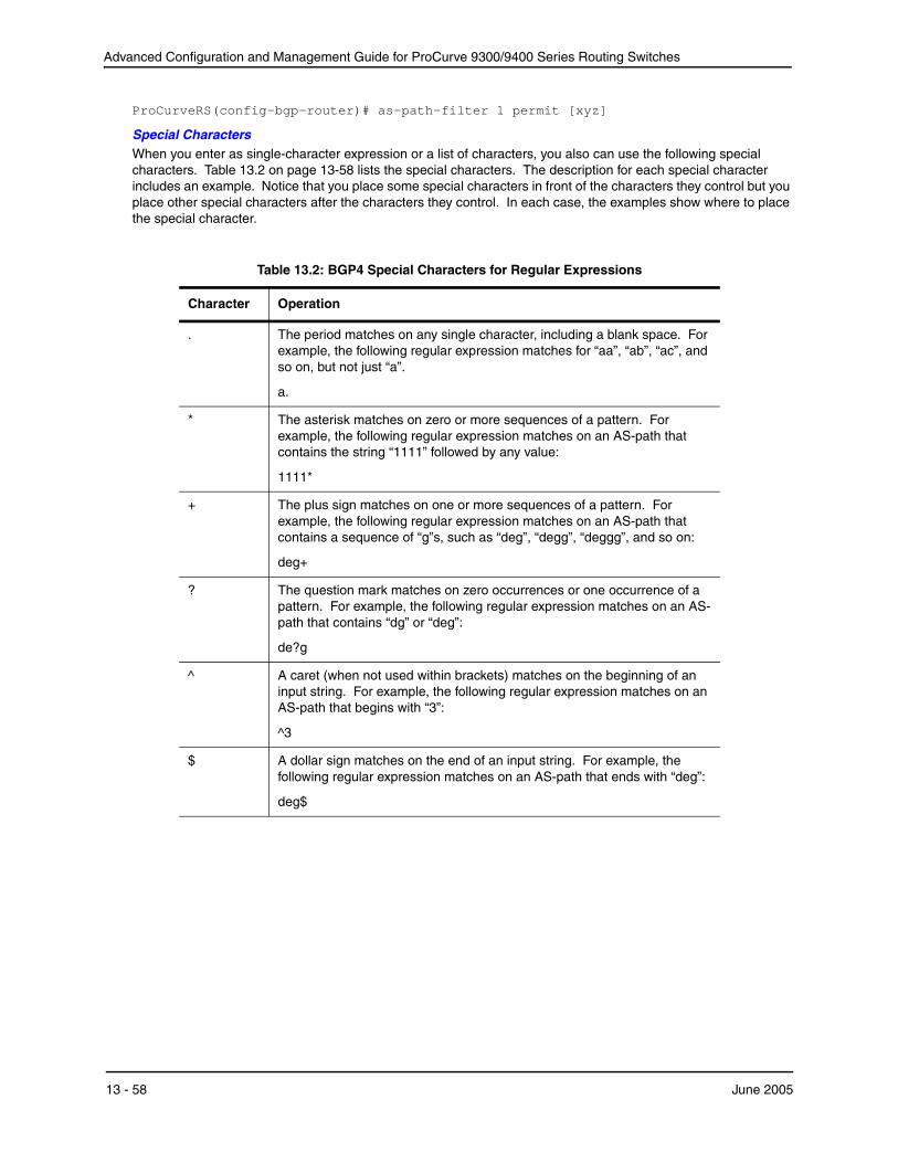
Advanced Configuration and Management Guide for ProCurve 9300/9400 Series Routing Switches
ProCurveRS(config-bgp-router)# as-path-filter 1 permit [xyz]
Special Characters When you enter as single-character expression or a list of characters, you also can use the following special characters. Table 13.2 on page 13-58 lists the special characters. The description for each special character includes an example. Notice that you place some special characters in front of the characters they control but you place other special characters after the characters they control. In each case, the examples show where to place the special character.
Table 13.2: BGP4 Special Characters for Regular Expressions
Character
.
*
+
?
^
$
Operation
The period matches on any single character, including a blank space. For example, the following regular expression matches for “aa”, “ab”, “ac”, and so on, but not just “a”.
a.
The asterisk matches on zero or more sequences of a pattern. For example, the following regular expression matches on an AS-path that contains the string “1111” followed by any value:
1111*
The plus sign matches on one or more sequences of a pattern. For example, the following regular expression matches on an AS-path that contains a sequence of “g”s, such as “deg”, “degg”, “deggg”, and so on:
deg+
The question mark matches on zero occurrences or one occurrence of a pattern. For example, the following regular expression matches on an ASpath that contains “dg” or “deg”:
de?g
A caret (when not used within brackets) matches on the beginning of an input string. For example, the following regular expression matches on an AS-path that begins with “3”:
^3
A dollar sign matches on the end of an input string. For example, the following regular expression matches on an AS-path that ends with “deg”:
deg$
13 - 58 June 2005
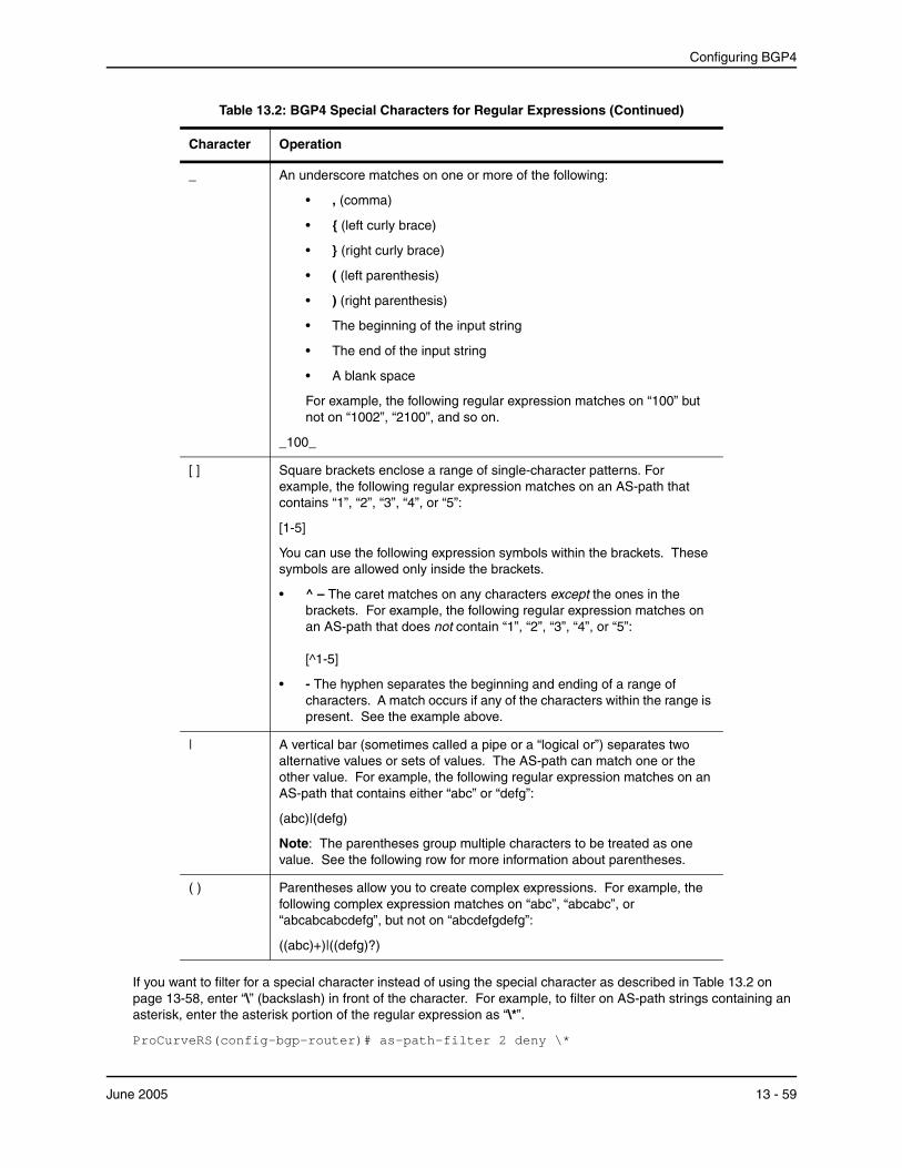
Configuring BGP4
Table 13.2: BGP4 Special Characters for Regular Expressions (Continued)
Character
_
[ ]
|
( )
Operation
An underscore matches on one or more of the following:
• , (comma)
• { (left curly brace)
• } (right curly brace)
• ( (left parenthesis)
• ) (right parenthesis)
• The beginning of the input string
• The end of the input string
• A blank space
For example, the following regular expression matches on “100” but not on “1002”, “2100”, and so on.
_100_
Square brackets enclose a range of single-character patterns. For example, the following regular expression matches on an AS-path that contains “1”, “2”, “3”, “4”, or “5”:
[1-5]
You can use the following expression symbols within the brackets. These symbols are allowed only inside the brackets.
• ^ – The caret matches on any characters except the ones in the brackets. For example, the following regular expression matches on an AS-path that does not contain “1”, “2”, “3”, “4”, or “5”:
[^1-5]
• - The hyphen separates the beginning and ending of a range of characters. A match occurs if any of the characters within the range is present. See the example above.
A vertical bar (sometimes called a pipe or a “logical or”) separates two alternative values or sets of values. The AS-path can match one or the other value. For example, the following regular expression matches on an AS-path that contains either “abc” or “defg”:
(abc)|(defg)
Note: The parentheses group multiple characters to be treated as one value. See the following row for more information about parentheses.
Parentheses allow you to create complex expressions. For example, the following complex expression matches on “abc”, “abcabc”, or “abcabcabcdefg”, but not on “abcdefgdefg”:
((abc)+)|((defg)?)
If you want to filter for a special character instead of using the special character as described in Table 13.2 on page 13-58, enter “\” (backslash) in front of the character. For example, to filter on AS-path strings containing an asterisk, enter the asterisk portion of the regular expression as “\*”.
ProCurveRS(config-bgp-router)# as-path-filter 2 deny \*
June 2005 13 - 59

Advanced Configuration and Management Guide for ProCurve 9300/9400 Series Routing Switches
To use the backslash as a string character, enter two slashes. For example, to filter on AS-path strings containing a backslash, enter the backslash portion of the regular expression as “\\”.
ProCurveRS(config-bgp-router)# as-path-filter 2 deny \\
Filtering Communities You can filter routes received from BGP4 neighbors based on community names. Use either of the following methods to do so.
A community is an optional attribute that identifies the route as a member of a user-defined class of routes. Community names are arbitrary values made of two five-digit integers joined by a colon. You determine what the name means when you create the community name as one of a route’s attributes. Each string in the community name can be a number from 0 – 65535.
This format allows you to easily classify community names. For example, a common convention used in community naming is to configure the first string as the local AS and the second string as the unique community within that AS. Using this convention, communities 1:10, 1:20, and 1:30 can be easily identified as member communities of AS 1.
The Routing Switch provides the following methods for filtering on community information:
• Community filters
• Community list ACLs
NOTE: The Routing Switch cannot actively support community filters and community list ACLs at the same time. Use one method or the other but do not mix methods.
NOTE: Once you define a filter or ACL, the default action for communities that do not match a filter or ACL is “deny”. To change the default action to “permit”, configure the last filter or ACL entry as “permit any any”.
Community filters or ACLs can be referred to by match statements in a route map.
Defining a Community Filter
USING THE CLI
To define filter 3 to permit routes that have the NO_ADVERTISE community, enter the following command:
ProCurveRS(config-bgp-router)# community-filter 3 permit no-advertise
Syntax: community-filter <num> permit | deny <num>:<num> | internet | local-as | no-advertise | no-export
The <num> parameter identifies the filter’s position in the community filter list and can be from 1 – 100. Thus, the community filter list can contain up to 100 filters. The router applies the filters in numerical order, beginning with the lowest-numbered filter. When a filter match is true, the router stops and does not continue applying filters from the list.
NOTE: If the filter is referred to by a route map’s match statement, the filter is applied in the order in which the filter is listed in the match statement.
The permit | deny parameter indicates the action the router takes if the filter match is true.
• If you specify permit, the router permits the route into the BGP4 table if the filter match is true.
• If you specify deny, the router denies the route from entering the BGP4 table if the filter match is true.
The <num>:<num> parameter indicates a specific community number to filter. Use this parameter to filter for a private (administrator-defined) community. You can enter up to 20 community numbers with the same command.
If you want to filter for the well-known communities “LOCAL_AS”, “NO_EXPORT” or “NO_ADVERTISE”, use the corresponding keyword (described below).
13 - 60 June 2005
Configuring BGP4
The internet keyword checks for routes that do not have the community attribute. Routes without a specific community are considered by default to be members of the largest community, the Internet.
The local-as keyword checks for routes with the well-known community “LOCAL_AS”. This community applies only to confederations. The Routing Switch advertises the route only within the sub-AS. For information about confederations, see “Configuring Confederations” on page 13-43.
The no-advertise keyword filters for routes with the well-known community “NO_ADVERTISE”. A route in this community should not be advertised to any BGP4 neighbors.
The no-export keyword filters for routes with the well-known community “NO_EXPORT”. A route in this community should not be advertised to any BGP4 neighbors outside the local AS. If the router is a member of a confederation, the Routing Switch advertises the route only within the confederation. For information about confederations, see “Configuring Confederations” on page 13-43.
USING THE WEB MANAGEMENT INTERFACE
1. Log on to the device using a valid user name and password for read-write access. The System configuration panel is displayed.
2. Click on the plus sign next to Configure in the tree view to expand the list of configuration options.
3. Click on the plus sign next to BGP in the tree view to expand the list of BGP option links.
4. Click on the Community Filter link to display the BGP Community Filter panel.
NOTE: If the device already has community filters, a table listing the filters is displayed. Click the Modify button to the right of the row describing a filter to change its configuration, or select the Add Community Filter link to display the BGP Community Filter panel.
5. Enter the filter’s position in the ID filter. The ID is the filter’s position in the community filter list and can be from 1 – 100. Thus, the community filter list can contain up to 100 filters. The router applies the filters in numerical order, beginning with the lowest-numbered filter. When a filter match is true, the router stops and does not continue applying filters from the list.
If the filter is referred to by a route map’s match statement, the filter is applied in the order in which the filter is listed in the match statement.
6. Select the action for the filter. You can select Deny or Permit:
• If you select Deny, the router denies the route from entering the BGP4 table if the filter match is true.
• If you select Permit, the router permits the route into the BGP4 table if the filter match is true.
7. Specify a well-known community you want the Routing Switch to apply to a route when the route matches the filter by selecting from the following:
• Internet – Filters for routes that do not have the community attribute. Routes without a specificcommunity are considered by default to be members of the largest community, the Internet.
• Local AS – Filters for routes with the well-known community “LOCAL_AS”. A route in this community should not be advertised outside the sub-AS. This community type applies to confederations.
• No Advertise – Filters for routes with the well-known community “NO_ADVERTISE”. A route in this community should not be advertised to any BGP4 neighbors.
• No Export – Filters for routes with the well-known community “NO_EXPORT”. A route in this community should not be advertised to any BGP4 neighbors outside the local AS. If the router is a member of a confederation, the Routing Switch advertises the route only within the confederation.
NOTE: If you want to filter on a private (administrator-defined) community, do not select one of these. Instead, enter the community number in the Community List field.
8. Specify private communities by entering the community names in the Community List field. Enter the names in the following format <num>:<num>. You can use commas or spaces to separate the names.
June 2005 13 - 61

Advanced Configuration and Management Guide for ProCurve 9300/9400 Series Routing Switches
9. Click the Add button (if you are adding a new filter) or the Modify button (if you are changing a filter) to apply the changes to the device’s running-config file.
10. Select the Save link at the bottom of the dialog, then select Yes when prompted to save the configuration change to the startup-config file on the device’s flash memory.
Defining a Community ACL
To configure a community ACL, use either of the following methods.
USING THE CLI
To configure community ACL 1, enter a command such as the following:
ProCurveRS(config)# ip community-list 1 permit 123:2
This command configures a community ACL that permits routes that contain community 123:2.
NOTE: See “Matching Based on Community ACL” on page 13-74 for information about how to use a community list as a match condition in a route map.
Syntax: ip community-list standard <string> [seq <seq-value>] deny | permit <community-num>
Syntax: ip community-list extended <string> [seq <seq-value>] deny | permit <community-num> | <regular-expression>
The <string> parameter specifies the ACL name. (If you enter a number, the CLI interprets the number as a text string.)
The standard or extended parameter specifies whether you are configuring a standard community ACL or an extended one. A standard community ACL does not support regular expressions whereas an extended one does. This is the only difference between standard and extended IP community lists.
The seq <seq-value> parameter is optional and specifies the community list’s sequence number. You can configure up to 199 entries in a community list. If you do not specify a sequence number, the software numbers them in increments of 5, beginning with number 5. The software interprets the entries in a community list in numerical order, beginning with the lowest sequence number.
The deny | permit parameter specifies the action the software takes if a route’s community list matches a match statement in this ACL. To configure the community-list match statements in a route map, use the match community command. See “Matching Based on Community ACL” on page 13-74.
The <community-num> parameter specifies the community type or community number. This parameter can have the following values:
• <num>:<num> – A specific community number
• internet – The Internet community
• no-export – The community of sub-ASs within a confederation. Routes with this community can be exported to other sub-ASs within the same confederation but cannot be exported outside the confederation to other ASs or otherwise sent to EBGP neighbors.
• local-as – The local sub-AS within the confederation. Routes with this community can be advertised only within the local subAS.
• no-advertise – Routes with this community cannot be advertised to any other BGP4 routers at all.
The <regular-expression> parameter specifies a regular expression for matching on community names. For information about regular expression syntax, see “Using Regular Expressions” on page 13-57. You can specify a regular expression only in an extended community ACL.
USING THE WEB MANAGEMENT INTERFACE
1. Log on to the device using a valid user name and password for read-write access. The System configuration panel is displayed.
2. Click on the plus sign next to Configure in the tree view to display the list of configuration options.
13 - 62 June 2005
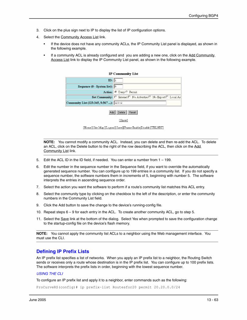
Configuring BGP4
3. Click on the plus sign next to IP to display the list of IP configuration options.
4. Select the Community Access List link.
• If the device does not have any community ACLs, the IP Community List panel is displayed, as shown in the following example.
• If a community ACL is already configured and you are adding a new one, click on the Add Community Access List link to display the IP Community List panel, as shown in the following example.
NOTE: You cannot modify a community ACL. Instead, you can delete and then re-add the ACL. To delete an ACL, click on the Delete button to the right of the row describing the ACL, then click on the Add Community List link.
5. Edit the ACL ID in the ID field, if needed. You can enter a number from 1 – 199.
6. Edit the number in the sequence number in the Sequence field, if you want to override the automatically generated sequence number. You can configure up to 199 entries in a community list. If you do not specify a sequence number, the software numbers them in increments of 5, beginning with number 5. The software interprets the entries in ascending sequence order.
7. Select the action you want the software to perform if a route’s community list matches this ACL entry.
8. Select the community type by clicking on the checkbox to the left of the description, or enter the community numbers in the Community List field.
9. Click the Add button to save the change to the device’s running-config file.
10. Repeat steps 6 – 9 for each entry in the ACL. To create another community ACL, go to step 5.
11. Select the Save link at the bottom of the dialog. Select Yes when prompted to save the configuration change to the startup-config file on the device’s flash memory.
NOTE: You cannot apply the community list ACLs to a neighbor using the Web management interface. You must use the CLI.
Defining IP Prefix Lists An IP prefix list specifies a list of networks. When you apply an IP prefix list to a neighbor, the Routing Switch sends or receives only a route whose destination is in the IP prefix list. You can configure up to 100 prefix lists. The software interprets the prefix lists in order, beginning with the lowest sequence number.
USING THE CLI
To configure an IP prefix list and apply it to a neighbor, enter commands such as the following:
ProCurveRS(config)# ip prefix-list Routesfor20 permit 20.20.0.0/24
June 2005 13 - 63

Advanced Configuration and Management Guide for ProCurve 9300/9400 Series Routing Switches
ProCurveRS(config)# router bgp ProCurveRS(config-bgp-router)# neighbor 10.10.10.1 prefix-list Routesfor20 out
These commands configure an IP prefix list named Routesfor20, which permits routes to network 20.20.0.0/24. The neighbor command configures the Routing Switch to use IP prefix list Routesfor20 to determine which routes to send to neighbor 10.10.10.1. The Routing Switch sends routes that go to 20.20.x.x to neighbor 10.10.10.1 because the IP prefix list explicitly permits these routes to be sent to the neighbor.
Syntax: ip prefix-list <name> [seq <seq-value>] [description <string>] deny | permit <network-addr>/<mask-bits> [ge <ge-value>] [le <le-value>]
The <name> parameter specifies the prefix list name. You use this name when applying the prefix list to a neighbor.
The description <string> parameter is a text string describing the prefix list.
The seq <seq-value> parameter is optional and specifies the IP prefix list’s sequence number. You can configure up to 100 prefix list entries. If you do not specify a sequence number, the software numbers them in increments of 5, beginning with prefix list entry 5. The software interprets the prefix list entries in numerical order, beginning with the lowest sequence number.
The deny | permit parameter specifies the action the software takes if a neighbor’s route is in this prefix list.
The prefix-list matches only on this network unless you use the ge <ge-value> or le <le-value> parameters. (See below.)
The <network-addr>/<mask-bits> parameter specifies the network number and the number of bits in the network mask.
You can specify a range of prefix length for prefixes that are more specific than <network-addr>/<mask-bits>.
• If you specify only ge <ge-value>, then the mask-length range is from <ge-value> to 32.
• If you specify only le <le-value>, then the mask-length range is from length to <le-value>.
The <ge-value> or <le-value> you specify must meet the following condition:
length < ge-value <= le-value <= 32
If you do not specify ge <ge-value> or le <le-value>, the prefix list matches only on the exact network prefix you specify with the <network-addr>/<mask-bits> parameter.
For the syntax of the neighbor command shown in the example above, see “Adding BGP4 Neighbors” onpage 13-13.
USING THE WEB MANAGEMENT INTERFACE
To configure an IP Prefix List, use the following procedure:
1. Log on to the device using a valid user name and password for read-write access. The System configuration panel is displayed.
2. Click on the plus sign next to Configure in the tree view to display the list of configuration options.
3. Click on the plus sign next to IP to display the list of IP configuration options.
4. Select the Prefix List link.
• If the device does not have any prefix list ACLs, the IP Prefix List panel is displayed, as shown in the following example.
• If a prefix list ACL is already configured and you are adding a new one, click on the Add IP Prefix List link
13 - 64 June 2005

Configuring BGP4
to display the IP Prefix List panel, as shown in the following example.
NOTE: You cannot modify an IP prefix list ACL. Instead, you can delete and then re-add the ACL. To delete an ACL, click on the Delete button to the right of the row describing the ACL, then click on the Add IP Prefix List link.
5. Edit a name in the Name field.
6. Enter a description in the Description field.
7. Edit the number in the sequence number in the Sequence field, if you want to override the automatically generated sequence number. You can configure up to 100 prefix list entries. If you do not specify a sequence number, the software numbers them in increments of 5, beginning with prefix list entry 5. The software interprets the prefix list entries in numerical order, beginning with the lowest sequence number.
8. Select the action you want the software to perform if a neighbor’s route is in this prefix list.
9. Enter the IP prefix by entering a network address and sub-net mask in the Address and Mask fields.
NOTE: If you do not specify a Greater Value or Less Value, this prefix list entry matches only on the exact network prefix you specified with the values in the Address and Mask fields.
10. Enter a number from 1 – 32 in the Greater Value field if you want the prefix list to match on prefixes that are more specific than the one you entered in the Address and Mask fields, in addition to matching on the prefix in those fields. The value you enter here specifies the minimum number of mask bits in the network mask. For example, if you enter 24 in the example panel shown above, the prefix list matches on all network numbers that are equal to or more specific than 20.20.0.0. Thus 20.20.1.0 and higher also match the prefix list.
11. Enter a number from 1 – 32 in the Less Value field if you want the prefix list to match on prefixes that are less specific than the one you entered in the Address and Mask fields, in addition to matching on the prefix in those fields.
12. Click the Add button to save the change to the device’s running-config file.
13. Repeat steps 5 – 12 for each IP prefix list entry.
14. Select the Save link at the bottom of the dialog. Select Yes when prompted to save the configuration change to the startup-config file on the device’s flash memory.
To apply the IP Prefix List to a neighbor, use the following procedure:
June 2005 13 - 65
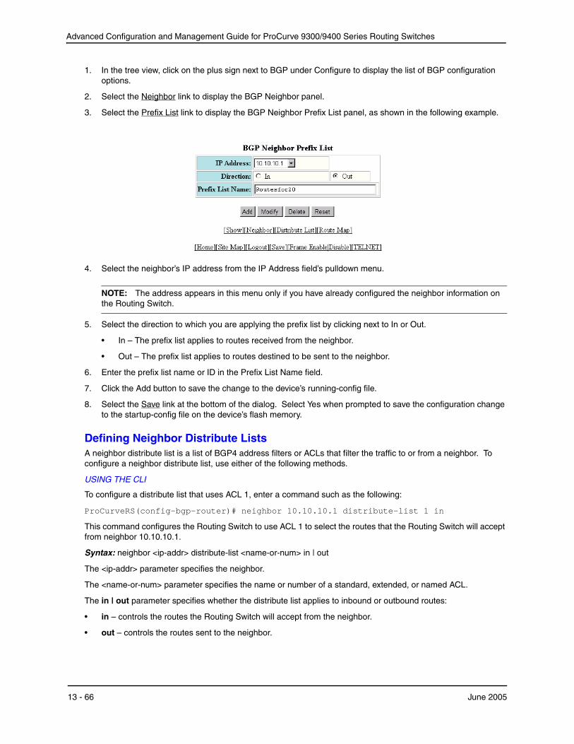
Advanced Configuration and Management Guide for ProCurve 9300/9400 Series Routing Switches
1. In the tree view, click on the plus sign next to BGP under Configure to display the list of BGP configuration options.
2. Select the Neighbor link to display the BGP Neighbor panel.
3. Select the Prefix List link to display the BGP Neighbor Prefix List panel, as shown in the following example.
4. Select the neighbor’s IP address from the IP Address field’s pulldown menu.
NOTE: The address appears in this menu only if you have already configured the neighbor information on the Routing Switch.
5. Select the direction to which you are applying the prefix list by clicking next to In or Out.
• In – The prefix list applies to routes received from the neighbor.
• Out – The prefix list applies to routes destined to be sent to the neighbor.
6. Enter the prefix list name or ID in the Prefix List Name field.
7. Click the Add button to save the change to the device’s running-config file.
8. Select the Save link at the bottom of the dialog. Select Yes when prompted to save the configuration change to the startup-config file on the device’s flash memory.
Defining Neighbor Distribute Lists A neighbor distribute list is a list of BGP4 address filters or ACLs that filter the traffic to or from a neighbor. To configure a neighbor distribute list, use either of the following methods.
USING THE CLI
To configure a distribute list that uses ACL 1, enter a command such as the following:
ProCurveRS(config-bgp-router)# neighbor 10.10.10.1 distribute-list 1 in
This command configures the Routing Switch to use ACL 1 to select the routes that the Routing Switch will accept from neighbor 10.10.10.1.
Syntax: neighbor <ip-addr> distribute-list <name-or-num> in | out
The <ip-addr> parameter specifies the neighbor.
The <name-or-num> parameter specifies the name or number of a standard, extended, or named ACL.
The in | out parameter specifies whether the distribute list applies to inbound or outbound routes:
• in – controls the routes the Routing Switch will accept from the neighbor.
• out – controls the routes sent to the neighbor.
13 - 66 June 2005

Configuring BGP4
NOTE: The command syntax shown above is new in software release 06.5.00. However, the neighbor <ipaddr> distribute-list in | out <num> command (where the direction is specified before the filter number) is the same as in earlier software releases. Use the new syntax when you are using an IP ACL with the distribute list. Use the old syntax when you are using a BGP4 address filter with the distribute list.
USING THE WEB MANAGEMENT INTERFACE
1. Log on to the device using a valid user name and password for read-write access. The System configuration panel is displayed.
2. Click on the plus sign next to Configure in the tree view to expand the list of configuration options.
3. Click on the plus sign next to BGP in the tree view to expand the list of BGP option links.
4. Click on the Neighbor link to display the BGP Neighbor panel.
NOTE: If the device already has neighbors, a table listing the neighbors is displayed. Click the Modify button to the right of the row describing the neighbor to change its configuration, or click the Add Neighbor link to display the BGP Neighbor configuration panel.
5. If you are adding a new neighbor or you need to change additional parameters, see the complete procedure in “Adding BGP4 Neighbors” on page 13-13.
6. Select the Distribute List link at the bottom of the panel to display the BGP Neighbor Distribute panel, as shown in the following example.
7. Select the neighbor’s IP address from the IP Address field’s pulldown menu.
NOTE: The address appears in this menu only if you have already configured the neighbor information on the Routing Switch.
8. Select the direction to which you are applying the distribute list by clicking next to In or Out.
• In – The distribute list applies to routes received from the neighbor.
• Out – The distribute list applies to routes destined to be sent to the neighbor.
9. Select the type of distribute list you are applying. You can select one of the following:
• Address Filter – a BGP4 address filter.
• IP Access List – an ACL.
10. Enter the address filter or ACL name or ID in the Access List field.
11. Click the Add button to save the change to the device’s running-config file.
June 2005 13 - 67

Advanced Configuration and Management Guide for ProCurve 9300/9400 Series Routing Switches
12. Select the Save link at the bottom of the dialog. Select Yes when prompted to save the configuration change to the startup-config file on the device’s flash memory.
Defining Route Maps A route map is a named set of match conditions and parameter settings that the router can use to modify route attributes and to control redistribution of the routes into other protocols. A route map consists of a sequence of up to 50 instances. If you think of a route map as a table, an instance is a row in that table. The router evaluates a route according to a route map’s instances in ascending numerical order. The route is first compared against instance 1, then against instance 2, and so on. As soon as a match is found, the router stops evaluating the route against the route map instances.
Route maps can contain match statements and set statements. Each route map contains a “permit” or “deny” action for routes that match the match statements.
• If the route map contains a permit action, a route that matches a match statement is permitted; otherwise, the route is denied.
• If the route map contains a deny action, a route that matches a match statement is denied.
• If a route does not match any match statements in the route map, the route is denied. This is the default action. To change the default action, configure the last match statement in the last instance of the route map to “permit any any”.
• If there is no match statement, the software considers the route to be a match.
• For route maps that contain address filters, AS-path filters, or community filters, if the action specified by a filter conflicts with the action specified by the route map, the route map’s action takes precedence over the individual filter’s action.
If the route map contains set statements, routes that are permitted by the route map’s match statements are modified according to the set statements.
Match statements compare the route against one or more of the following:
• The route’s BGP4 MED (metric)
• A sequence of AS-path filters
• A sequence of community filters
• A sequence of address filters
• The IP address of the next hop router
• The route’s tag
• For OSPF routes only, the route’s type (internal, external type-1, or external type-2)
• An AS-path ACL
• A community ACL
• An IP prefix list
• An IP ACL
For routes that match all of the match statements, the route map’s set statements can perform one or more of the following modifications to the route’s attributes:
• Prepend AS numbers to the front of the route’s AS-path. By adding AS numbers to the AS-path, you can cause the route to be less preferred when compared to other routes on the basis of the length of the AS-path.
• Add a user-defined tag to the route or add an automatically calculated tag to the route.
• Set the community value.
• Set the local preference.
• Set the MED (metric).
13 - 68 June 2005
Configuring BGP4
• Set the IP address of the next hop router.
• Set the origin to IGP or INCOMPLETE.
• Set the weight.
For example, when you configure parameters for redistributing routes into RIP, one of the optional parameters is a route map. If you specify a route map as one of the redistribution parameters, the router will match the route against the match statements in the route map. If a match is found and if the route map contains set statements, the router will set attributes in the route according to the set statements.
To create a route map, you define instances of the map. Each instance is identified by a sequence number. A route map can contain up to 50 instances.
To define a route map, use the procedures in the following sections.
Entering the Route Map Into the Software
USING THE CLI
To add instance 1 of a route map named “GET_ONE” with a permit action, enter the following command.
ProCurveRS(config)# route-map GET_ONE permit 1 ProCurveRS(config-routemap GET_ONE)#
Syntax: [no] route-map <map-name> permit | deny <num>
As shown in this example, the command prompt changes to the Route Map level. You can enter the match andset statements at this level. See “Specifying the Match Conditions” on page 13-70 and “Setting Parameters in the Routes” on page 13-76.
The <map-name> is a string of characters that names the map. Map names can be up to 32 characters in length.
The permit | deny parameter specifies the action the router will take if a route matches a match statement.
• If you specify deny, the Routing Switch does not advertise or learn the route.
• If you specify permit, the Routing Switch applies the match and set statements associated with this route map instance.
The <num> parameter specifies the instance of the route map you are defining. Each route map can have up to 50 instances.
To delete a route map, enter a command such as the following. When you delete a route map, all the permit and deny entries in the route map are deleted.
ProCurveRS(config)# no route-map Map1
This command deletes a route map named “Map1”. All entries in the route map are deleted.
To delete a specific instance of a route map without deleting the rest of the route map, enter a command such as the following:
ProCurveRS(config)# no route-map Map1 permit 10
This command deletes the specified instance from the route map but leaves the other instances of the route map intact.
USING THE WEB MANAGEMENT INTERFACE
1. Log on to the device using a valid user name and password for read-write access. The System configuration panel is displayed.
2. Click on the plus sign next to Configure in the tree view to expand the list of configuration options.
3. Click on the plus sign next to BGP in the tree view to expand the list of BGP option links.
4. Click on the Route Map Filter link to display the BGP Route Map Filter panel.
• If the device does not have any BGP route map filters configured, the BGP Route Map Filter configuration panel is displayed, as shown in the following example.
June 2005 13 - 69

Advanced Configuration and Management Guide for ProCurve 9300/9400 Series Routing Switches
• If BGP route map filters are already configured and you are adding a new one, click on the Route Map Filter link to display the BGP Route Map Filter configuration panel, as shown in the following example.
• If you are modifying an existing BGP route map filter, click on the Modify button to the right of the row describing the filter to display the BGP Route Map Filter configuration panel, as shown in the following example.
5. Enter the name of the route map in the Route Map Name field.
6. Enter the sequence (instance) number in the Sequence field. The Routing Switch applies the instances in ascending numerical order. Once an instance comparison results in a “true” evaluation, the Routing Switch stops applying instances and applies the match and set statements you configure for the instance. See “Specifying the Match Conditions” on page 13-70 and “Setting Parameters in the Routes” on page 13-76.
7. Select the action you want the Routing Switch to perform if the comparison results in a “true” value:
• If you select Deny, the Routing Switch does not advertise or learn the route.
• If you select Permit, the Routing Switch applies the match and set statements associated with this route map instance.
8. Click the Add button to apply the changes to the device’s running-config file.
9. Select the Save link at the bottom of the dialog. Select Yes when prompted to save the configuration change to the startup-config file on the device’s flash memory.
Specifying the Match Conditions
Use the following command to define the match conditions for instance 1 of the route map GET_ONE. This instance compares the route updates against BGP4 address filter 11.
ProCurveRS(config-routemap GET_ONE)# match address-filters 11
Syntax: match [as-path <num>] |[address-filters | as-path-filters | community-filters <num,num,...>] | [community <num>] | [community <acl> exact-match] |[ip address <acl> | prefix-list <string>] | [ip route-source <acl> | prefix <name>][metric <num>] | [next-hop <address-filter-list>] | [nlri multicast | unicast | multicast unicast] |[route-type internal | external-type1 | external-type2] | [tag <tag-value>]
The as-path <num> parameter specifies an AS-path ACL. You can specify up to five AS-path ACLs. Toconfigure an AS-path ACL, use the ip as-path access-list command. See “Defining an AS-Path ACL” onpage 13-56.
13 - 70 June 2005

Configuring BGP4
The address-filters | as-path-filters | community-filters <num,num,...> parameter specifies a filter or list of filters to be matched for each route. The router treats the first match as the best match. If a route does not match any filter in the list, then the router considers the match condition to have failed. To configure these types of filters, use commands at the BGP configuration level.
• To configure an address filter, see “Filtering Specific IP Addresses” on page 13-52.
• To configure an AS-path filter or AS-path ACL, see “Filtering AS-Paths” on page 13-54.
• To configure a community filter or community ACL, see “Filtering Communities” on page 13-60.
You can enter up to six community names on the same command line.
NOTE: The filters must already be configured.
The community <num> parameter specifies a community ACL.
NOTE: The ACL must already be configured.
The community <acl> exact-match parameter matches a route if (and only if) the route's community attributes field contains the same community numbers specified in the match statement.
The ip address | next-hop <acl-num> | prefix-list <string> parameter specifies an ACL or IP prefix list. Use this parameter to match based on the destination network or next-hop gateway. To configure an IP ACL for use with this command, use the ip access-list command. See “Software-Based IP Access Control Lists (ACLs)” on page 4-1. To configure an IP prefix list, use the ip prefix-list command. See “Defining IP Prefix Lists” on page 13-63.
The ip route-source <acl> | prefix <name> parameter matches based on the source of a route (the IP address of the neighbor from which the HP device learned the route).
The metric <num> parameter compares the route’s MED (metric) to the specified value.
The next-hop <address-filter-list> parameter compares the IP address of the route’s next hop to the specified IP address filters. The filters must already be configured.
The nlri multicast | unicast | multicast unicast parameter specifies whether you want the route map to match on multicast routes, unicast routes, or both route types.
NOTE: By default, route maps apply to both unicast and multicast traffic.
The route-type internal | external-type1 | external-type2 parameter applies only to OSPF routes. This parameter compares the route’s type to the specified value.
The tag <tag-value> parameter compares the route’s tag to the specified value.
USING THE WEB MANAGEMENT INTERFACE
NOTE: To simplify testing and configuration, you can specify an option and then choose whether to activate it. To activate an option, select the checkbox in front of the option’s field. Leave the checkbox unselected to leave the option inactive.
1. If you have just added the route map and the map is displayed in the BGP Route Map Filter panel, go to step 7. Otherwise, go to step 2.
2. Log on to the device using a valid user name and password for read-write access. The System configuration panel is displayed.
3. Click on the plus sign next to Configure in the tree view to expand the list of configuration options.
4. Click on the plus sign next to BGP in the tree view to expand the list of BGP option links.
5. Click on the Route Map Filter link to display a table listing the configured BGP route maps.
6. Click Modify next to the route map you want to configure to display the map in the BGP Route Map Filter panel.
June 2005 13 - 71
Advanced Configuration and Management Guide for ProCurve 9300/9400 Series Routing Switches
7. Select the Route Map Match link at the bottom of the panel to display the BGP Route Map Match panel.
8. Select the sequence (instance) from the Route Map Name Sequence field’s pulldown list. The Routing Switch applies the instances in ascending numerical order and stops after the first match.
9. For OSPF routes, select the one of the following route types—Internal, External1, or External2.
10. Select the type of ACL or filter you are adding as a match condition. You can select more than one ACL or filter type. In this example, select AS Path Access List.
NOTE: The AS-path, community, and address filters must already be configured.
NOTE: The Routing Switch does not actively support both filters and ACLs at the same time. Use one method or the other.
NOTE: IP prefix lists and neighbor distribute lists provide separate means for the same type of filtering. To simplify configuration, Hewlett-Packard recommends you use one method or the other but do not mix them.
11. Enter the filter or ACL numbers or names in the entry fields next to the filter or ACL types you selected.
12. Optionally enter an IP address against which you want to compare the route updates’ next-hop attribute. Enter the address in the Next Hop List field. Also select the checkbox in front of the field.
13. Optionally enter a tag value against which you want to compare the updates in the Tag List field. Also select the checkbox in front of the field.
14. Optionally enter a MED (metric) value against which you want to compare the route updates in the Metric field. Also select the checkbox in front of the field.
15. Click the Apply button to apply the changes to the device’s running-config file.
16. Select the Save link at the bottom of the dialog. Select Yes when prompted to save the configuration change to the startup-config file on the device’s flash memory.
Match Examples Using ACLs
The following sections show some detailed examples of how to configure route maps that include match statements that match on ACLs.
Matching Based on AS-Path ACL To construct match statements for a route map that match based on AS-path information, use either of the following methods.
USING THE CLI
To construct a route map that matches based on AS-path ACL 1, enter the following commands:
ProCurveRS(config)# route-map PathMap permit 1 ProCurveRS(config-routemap PathMap)# match as-path 1
Syntax: match as-path <num>
The <num> parameter specifies an AS-path ACL and can be a number from 1 – 199. You can specify up to five AS-path ACLs. To configure an AS-path ACL, use the ip as-path access-list command. See “Defining an AS-Path ACL” on page 13-56.
USING THE WEB MANAGEMENT INTERFACE
1. Log on to the device using a valid user name and password for read-write access. The System configuration panel is displayed.
2. Click on the plus sign next to Configure in the tree view to expand the list of configuration options.
3. Click on the plus sign next to BGP in the tree view to expand the list of BGP option links.
4. Click on the Route Map Filter link to display the BGP Route Map Filter panel.
13 - 72 June 2005

Configuring BGP4
• If the device does not have any BGP route map filters configured, the BGP Route Map Filter configuration panel is displayed, as shown in the following example.
• If BGP route map filters are already configured and you are adding a new one, click on the Route Map Filter link to display the BGP Route Map Filter configuration panel, as shown in the following example.
• If you are modifying an existing BGP route map filter, click on the Modify button to the right of the row describing the filter to display the BGP Route Map Filter configuration panel, as shown in the following example.
5. Enter the name of the route map in the Route Map Name field.
6. Enter the sequence (instance) number in the Sequence field. The Routing Switch applies the instances in ascending numerical order. Once an instance comparison results in a “true” evaluation, the Routing Switch stops applying instances and applies the match and set statements you configure for the instance.
7. Select the action you want the Routing Switch to perform if the comparison results in a “true” value:
• If you select Deny, the Routing Switch does not advertise or learn the route.
• If you select Permit, the Routing Switch applies the match and set statements associated with this route map instance.
8. Click the Add button to apply the changes to the device’s running-config file.
9. Select the Route Map Match link at the bottom of the panel to display the BGP Route Map Match panel, as shown in the following example.
June 2005 13 - 73
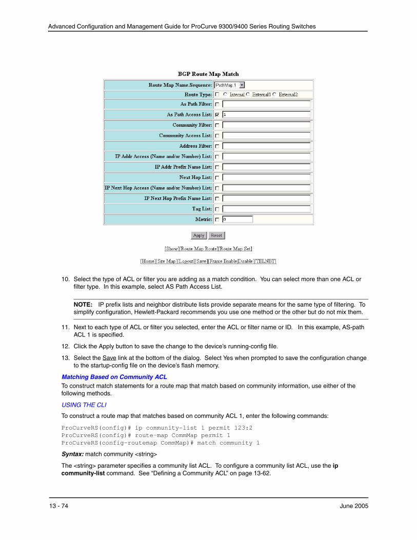
Advanced Configuration and Management Guide for ProCurve 9300/9400 Series Routing Switches
10. Select the type of ACL or filter you are adding as a match condition. You can select more than one ACL or filter type. In this example, select AS Path Access List.
NOTE: IP prefix lists and neighbor distribute lists provide separate means for the same type of filtering. To simplify configuration, Hewlett-Packard recommends you use one method or the other but do not mix them.
11. Next to each type of ACL or filter you selected, enter the ACL or filter name or ID. In this example, AS-path ACL 1 is specified.
12. Click the Apply button to save the change to the device’s running-config file.
13. Select the Save link at the bottom of the dialog. Select Yes when prompted to save the configuration change to the startup-config file on the device’s flash memory.
Matching Based on Community ACL To construct match statements for a route map that match based on community information, use either of the following methods.
USING THE CLI
To construct a route map that matches based on community ACL 1, enter the following commands:
ProCurveRS(config)# ip community-list 1 permit 123:2 ProCurveRS(config)# route-map CommMap permit 1 ProCurveRS(config-routemap CommMap)# match community 1
Syntax: match community <string>
The <string> parameter specifies a community list ACL. To configure a community list ACL, use the ip community-list command. See “Defining a Community ACL” on page 13-62.
13 - 74 June 2005

Configuring BGP4
USING THE WEB MANAGEMENT INTERFACE
Use the procedure in “Matching Based on AS-Path ACL” on page 13-72, but select Community Access List instead of AS Path Access List.
Matching Based on Destination Network To construct match statements for a route map that match based on destination network, use either of the following methods. You can use the results of an IP ACL or an IP prefix list as the match condition.
USING THE CLI
To construct a route map that matches based on destination network, enter commands such as the following:
ProCurveRS(config)# route-map NetMap permit 1 ProCurveRS(config-routemap NetMap)# match ip address 1
Syntax: match ip address <name-or-num>
Syntax: match ip address prefix-list <name>
The <name-or-num> parameter with the first command specifies an IP ACL and can be a number from 1 – 199 or the ACL name if it is a named ACL. To configure an IP ACL, use the ip access-list or access-list command. See “Software-Based IP Access Control Lists (ACLs)” on page 4-1.
The <name> parameter with the second command specifies an IP prefix list name. To configure an IP prefix list, see “Defining IP Prefix Lists” on page 13-63.
USING THE WEB MANAGEMENT INTERFACE
Use the procedure in “Matching Based on AS-Path ACL” on page 13-72, but select IP Addr Access (Name and/or Number) List instead of AS Path Access List.
Matching Based on Next-Hop Router To construct match statements for a route map that match based on the IP address of the next-hop router, use either of the following methods. You can use the results of an IP ACL or an IP prefix list as the match condition.
USING THE CLI
To construct a route map that matches based on the next-hop router, enter commands such as the following:
ProCurveRS(config)# route-map HopMap permit 1 ProCurveRS(config-routemap HopMap)# match ip next-hop 2
Syntax: match ip next-hop <num>
Syntax: match ip next-hop prefix-list <name>
The <num> parameter with the first command specifies an IP ACL and can be a number from 1 – 199 or the ACL name if it is a named ACL. To configure an IP ACL, use the ip access-list or access-list command. See “Software-Based IP Access Control Lists (ACLs)” on page 4-1.
The <name> parameter with the second command specifies an IP prefix list name. To configure an IP prefix list, see “Defining IP Prefix Lists” on page 13-63.
USING THE WEB MANAGEMENT INTERFACE
Use the procedure in “Matching Based on AS-Path ACL” on page 13-72, but select IP Next Hop Access (Name and/or Number) List instead of AS Path Access List.
Matching Based on the Route Source To match a BGP4 route based on its source, use the match ip route-source statement. Here is an example:
ProCurveRS(config)# access-list 10 permit 192.168.6.0 0.0.0.255 ProCurveRS(config)# route-map bgp1 permit 1 ProCurveRS(config-routemap bgp1)# match ip route-source 10
The first command configures an IP ACL that matches on routes received from 192.168.6.0/24. The remaining commands configure a route map that matches on all BGP4 routes advertised by the BGP4 neighbors whose addresses match addresses in the IP prefix list. You can add a set statement to change a route attribute in the
June 2005 13 - 75
Advanced Configuration and Management Guide for ProCurve 9300/9400 Series Routing Switches
routes that match. You also can use the route map as input for other commands, such as the neighbor and network commands and some show commands.
Syntax: match ip route-source <acl> | prefix <name>
The <acl> | prefix <name> parameter specifies the name or ID of an IP ACL, or an IP prefix list.
Matching On Routes Containing a Specific Set of Communities Previous software releases enable you to match routes based on the presence of a community name or number in a route. Software release 07.5.04 extends this support by enabling you to match when a route contains exactly the set of communities you specify. To match based on a set of communities, configure a community ACL that lists the communities, then compare routes against the ACL.
Here is an example.
ProCurveRS(config)# ip community-list standard std_1 permit 12:34 no-export ProCurveRS(config)# route-map bgp2 permit 1 ProCurveRS(config-routemap bgp2)# match community std_1 exact-match
The first command configures a community ACL that contains community number 12:34 and community name noexport. The remaining commands configure a route map that matches the community attributes field in BGP4 routes against the set of communities in the ACL. A route matches the route map only if the route contains all the communities in the ACL and no other communities.
Syntax: match community <acl> exact-match
The <acl> parameter specifies the name of a community list ACL. You can specify up to five ACLs. Separate the ACL names or IDs with spaces.
Here is another example.
ProCurveRS(config)# ip community-list standard std_2 permit 23:45 56:78ProCurveRS(config)# route-map bgp3 permit 1ProCurveRS(config-routemap bgp3)# match community std_1 std_2 exact-match
These commands configure an additional community ACL, std_2, that contains community numbers 23:45 and 57:68. Route map bgp3 compares each BGP4 route against the sets of communities in ACLs std_1 and std_2. A BGP4 route that contains either but not both sets of communities matches the route map. For example, a route containing communities 23:45 and 57:68 matches. However, a route containing communities 23:45, 57:68 and 12:34, or communities 23:45, 57:68, 12:34, and no-export does not match. To match, the route’s communities must be the same as those in exactly one of the community ACLs used by the match community statement.
Setting Parameters in the Routes
Use the following command to define a set statement that prepends an AS number to the AS path on each route that matches the corresponding match statement.
ProCurveRS(config-routemap GET_ONE)# set as-path prepend 65535
Syntax: set [as-path [prepend <as-num,as-num,...>]] | [automatic-tag] | [comm-list <acl> delete] |[community <num>:<num> | <num> | internet | local-as | no-advertise | no-export] | [dampening [<half-life> <reuse> <suppress> <max-suppress-time>]][[default] interface null0 ] | [ip [default] next hop <ip-addr>][ip next-hop peer-address] |[local-preference <num>] | [metric [+ | - ]<num> | none] | [metric-type type-1 | type-2] | [metric-type internal] |
13 - 76 June 2005

Configuring BGP4
[next-hop <ip-addr>] | [nlri multicast | unicast | multicast unicast] |[origin igp | incomplete] | [tag <tag-value>] | [weight <num>]
The as-path prepend <num,num,...> parameter adds the specified AS numbers to the front of the AS-path list for the route.
The automatic-tag parameter calculates and sets an automatic tag value for the route.
NOTE: This parameter applies only to routes redistributed into OSPF.
The comm-list parameter deletes a community from a BGP4 route’s community attributes field.
The community parameter sets the community attribute for the route to the number or well-known type you specify.
The dampening [<half-life> <reuse> <suppress> <max-suppress-time>] parameter sets route dampening parameters for the route. The <half-life> parameter specifies the number of minutes after which the route’s penalty becomes half its value. The <reuse> parameter specifies how low a route’s penalty must become before the route becomes eligible for use again after being suppressed. The <suppress> parameter specifies how high a route’s penalty can become before the Routing Switch suppresses the route. The <max-suppress-time> parameter specifies the maximum number of minutes that a route can be suppressed regardless of how unstable it is. For information and examples, see “Configuring Route Flap Dampening” on page 13-83.
The [default] interface null0 parameter redirects the traffic to the specified interface. You can send the traffic to the null0 interface, which is the same as dropping the traffic. You can specify more than one interface, in which case the Routing Switch uses the first available port. If the first port is unavailable, the Routing Switch sends the traffic to the next port in the list. If you specify default, the route map redirects the traffic to the specified interface only if the Routing Switch does not already have explicit routing information for the traffic. This option is used in Policy-Based Routing (PBR). See “Policy-Based Routing (PBR)” on page 4-52.
The ip [default] next hop <ip-addr> parameter sets the next-hop IP address for traffic that matches a match statement in the route map. If you specify default, the route map sets the next-hop gateway only if the Routing Switch does not already have explicit routing information for the traffic. This option is used in Policy-Based Routing (PBR). See “Policy-Based Routing (PBR)” on page 4-52.
The ip next-hop peer-address parameter sets the BGP4 next hop for a route to the specified neighbor address.
The local-preference <num> parameter sets the local preference for the route. You can set the preference to a value from 0 – 4294967295.
The metric [+ | - ]<num> | none parameter sets the MED (metric) value for the route. The default MED value is 0. You can set the preference to a value from 0 – 4294967295.
• set metric <num> – Sets the route’s metric to the number you specify.
• set metric +<num> – Increases route’s metric by the number you specify.
• set metric -<num> – Decreases route’s metric by the number you specify.
• set metric none – Removes the metric from the route (removes the MED attribute from the BGP4 route).
The metric-type type-1 | type-2 parameter changes the metric type of a route redistributed into OSPF.
The metric-type internal parameter sets the route's MED to the same value as the IGP metric of the BGP4 nexthop route. The parameter does this when advertising a BGP4 route to an EBGP neighbor.
The next-hop <ip-addr> parameter sets the IP address of the route’s next hop router.
The nlri multicast | unicast | multicast unicast parameter redistributes routes into the multicast Routing Information Base (RIB) instead of the unicast RIB.
June 2005 13 - 77

Advanced Configuration and Management Guide for ProCurve 9300/9400 Series Routing Switches
NOTE: Setting the NLRI type to multicast applies only when you are using the route map to redistribute directlyconnected routes. Otherwise, the set option is ignored.
The origin igp | incomplete parameter sets the route’s origin to IGP or INCOMPLETE.
The tag <tag-value> parameter sets the route’s tag. You can specify a tag value from 0 – 4294967295.
NOTE: This parameter applies only to routes redistributed into OSPF.
NOTE: You also can set the tag value using a table map. The table map changes the value only when the Routing Switch places the route in the IP route table instead of changing the value in the BGP route table. See “Using a Table Map To Set the Tag Value” on page 13-80.
The weight <num> parameter sets the weight for the route. You can specify a weight value from 0 – 4294967295.
USING THE WEB MANAGEMENT INTERFACE
NOTE: To simplify testing and configuration, you can specify an option and then choose whether to activate it. To activate an option, select the checkbox in front of the option’s field. Leave the checkbox unselected to leave the option inactive.
1. If you have just added the route map and the map is displayed in the BGP Route Map Filter panel, go to step 7. Otherwise, go to step 2.
2. Log on to the device using a valid user name and password for read-write access. The System configuration panel is displayed.
3. Click on the plus sign next to Configure in the tree view to expand the list of configuration options.
4. Click on the plus sign next to BGP in the tree view to expand the list of BGP option links.
5. Click on the Route Map Filter link to display a table listing the configured BGP route maps.
6. Click Modify next to the route map you want to configure to display the map in the BGP Route Map Filter panel.
7. Select the Route Map Set link at the bottom of the panel to display the BGP Route Map Set panel.
8. Select the sequence (instance) from the Route Map Name Sequence field’s pulldown list.
9. Optionally select the origin. You can select IGP or Incomplete. Also select the checkbox in front of the field.
10. Optionally enter AS numbers to append to the AS path. Also select the checkbox in front of the field.
11. Optionally select Auto Tag. The Routing Switch calculates and sets an automatic tag value for the route.
12. If you did not select Auto Tag and you instead want to set the tag value manually, enter a tag value from 0 – 4294967295 in the Tag field. Also select the checkbox in front of the field.
13. Optionally select the community type and also select the checkbox.
14. For a private community, enter the community number in the Number field. You can enter more than one community. Use commas or spaces to separate the community names.
15. Select Additive of you want the Set statement to add the specified community.
16. Optionally enter a local preference in the Local Preference and also select the checkbox in front of the field. The default local preference is 100. You can set the preference to a value from 0 – 4294967295.
17. Optionally enter a metric (MED) in the Metric field and also select the checkbox in front of the field. The default MED value is 0. You can set the preference to a value from 0 – 4294967295.
18. Optionally enter the Next Hop IP address in the NextHop field and also select the checkbox in front of the field.
13 - 78 June 2005

Configuring BGP4
19. Optionally enter a weight in the Weight field and also select the checkbox in front of the field. You can specify a weight value from 0 – 4294967295.
20. Click the Apply button to apply the changes to the device’s running-config file.
21. Select the Save link at the bottom of the dialog. Select Yes when prompted to save the configuration change to the startup-config file on the device’s flash memory.
Setting a BP4 Route’s MED to the same Value as the IGP Metric of the Next-Hop Route To set a route's MED to the same value as the IGP metric of the BGP4 next-hop route, when advertising the route to a neighbor, enter commands such as the following:
ProCurveRS(config)# access-list 1 permit 192.168.9.0 0.0.0.255 ProCurveRS(config)# route-map bgp4 permit 1 ProCurveRS(config-routemap bgp4)# match ip address 1 ProCurveRS(config-routemap bgp4)# set metric-type internal
The first command configures an ACL that matches on routes with destination network 192.168.9.0. The remaining commands configure a route map that matches on the destination network in ACL 1, then sets the metric type for those routes to the same value as the IGP metric of the BGP4 next-hop route.
Syntax: set metric-type internal
Setting the Next Hop of a BGP4 Route To set the next hop address of a BGP4 route to a neighbor address, enter commands such as the following:
ProCurveRS(config)# route-map bgp5 permit 1 ProCurveRS(config-routemap bgp5)# match ip address 1 ProCurveRS(config-routemap bgp5)# set ip next-hop peer-address
These commands configure a route map that matches on routes whose destination network is specified in ACL 1, and sets the next hop in the routes to the neighbor address (inbound filtering) or the local IP address of the BGP4 session (outbound filtering).
Syntax: set ip next-hop peer-address
The value that the software substitutes for peer-address depends on whether the route map is used for inbound filtering or outbound filtering:
• When you use the set ip next-hop peer-address command in an inbound route map filter, peer-address substitutes for the neighbor’s IP address.
• When you use the set ip next-hop peer-address command in an outbound route map filter, peer-address substitutes for the local IP address of the BGP4 session.
NOTE: You can use this command for a peer group configuration.
Deleting a Community from a BGP4 Route To delete a community from a BGP4 route’s community attributes field, enter commands such as the following:
ProCurveRS(config)# ip community-list standard std_3 permit 12:99 12:86 ProCurveRS(config)# route-map bgp6 permit 1 ProCurveRS(config-routemap bgp6)# match ip address 1 ProCurveRS(config-routemap bgp6)# set comm-list std_3 delete
The first command configures a community ACL containing community numbers 12:99 and 12:86. The remaining commands configure a route map that matches on routes whose destination network is specified in ACL 1, and deletes communities 12:99 and 12:86 from those routes. The route does not need to contain all the specified communities in order for them to be deleted. For example, if a route contains communities 12:86, 33:44, and 66:77, community 12:86 is deleted.
Syntax: set comm-list <acl> delete
The <acl> parameter specifies the name of a community list ACL.
June 2005 13 - 79

Advanced Configuration and Management Guide for ProCurve 9300/9400 Series Routing Switches
Using a Table Map To Set the Tag Value Route maps that contain set statements change values in routes when the routes are accepted by the route map. For inbound route maps (route maps that filter routes received from neighbors), this means that the routes are changed before they enter the BGP4 route table.
For tag values, if you do not want the value to change until a route enters the IP route table, you can use a table map to change the value. A table map is a route map that you have associated with the IP routing table. The Routing Switch applies the set statements for tag values in the table map to routes before adding them to the route table.
To configure a table map, you configure the route map, then identify it as a table map. The table map does not require separate configuration. You create it simply by calling an existing route map a table map. You can have one table map.
NOTE: Use table maps only for setting the tag value. Do not use table maps to set other attributes. To set other route attributes, use route maps or filters.
USING THE CLI
To create a route map and identify it as a table map, enter commands such as following. These commands create a route map that uses an address filter. For routes that match the address filter, the route map changes the tag value to 100. This route map is then identified as a table map. As a result, the route map is applied only to routes that the Routing Switch places in the IP route table. The route map is not applied to all routes. This example assumes that address filter 11 has already been configured.
ProCurveRS(config)# route-map TAG_IP permit 1 ProCurveRS(config-routemap TAG_IP)# match address-filters 11 ProCurveRS(config-routemap TAG_IP)# set tag 100 ProCurveRS(config-routemap TAG_IP)# router bgp ProCurveRS(config-bgp-router)# table-map TAG_IP
USING THE WEB MANAGEMENT INTERFACE
1. Log on to the device using a valid user name and password for read-write access. The System configuration panel is displayed.
2. Use the Web management procedures in “Defining Route Maps” on page 13-68 to create the route map.
3. Click on the plus sign next to Configure in the tree view to expand the list of configuration options.
4. Click on the plus sign next to BGP in the tree view to expand the list of BGP option links.
5. Click on the General link to display the BGP configuration panel.
6. Select the route map name from the Table Map field’s pulldown menu.
7. Click the Apply button to apply the changes to the device’s running-config file.
8. Select the Save link at the bottom of the dialog. Select Yes when prompted to save the configuration change to the startup-config file on the device’s flash memory.
Configuring Cooperative BGP4 Route Filtering By default, the Routing Switch performs all filtering of incoming routes locally, on the Routing Switch itself. You can use cooperative BGP4 route filtering to cause the filtering to be performed by a neighbor before it sends the routes to the Routing Switch. Cooperative filtering conserves resources by eliminating unnecessary route updates and filter processing. For example, the Routing Switch can send a deny filter to its neighbor, which the neighbor uses to filter out updates before sending them to the Routing Switch. The neighbor saves the resources it would otherwise use to generate the route updates, and the Routing Switch saves the resources it would use to filter out the routes.
When you enable cooperative filtering, the Routing Switch advertises this capability in its Open message to the neighbor when initiating the neighbor session. The Open message also indicates whether the Routing Switch is configured to send filters, receive filters or both, and the types of filters it can send or receive. The Routing Switch sends the filters as Outbound Route Filters (ORFs) in Route Refresh messages.
13 - 80 June 2005

Configuring BGP4
To configure cooperative filtering, perform the following tasks on the Routing Switch and on its BGP4 neighbor:
• Configure the filter.
NOTE: The current release supports cooperative filtering only for filters configured using IP prefix lists.
• Apply the filter as in inbound filter to the neighbor.
• Enable the cooperative route filtering feature on the Routing Switch. You can enable the Routing Switch to send ORFs to the neighbor, to receive ORFs from the neighbor, or both. The neighbor uses the ORFs you send as outbound filters when it sends routes to the Routing Switch. Likewise, the Routing Switch uses the ORFs it receives from the neighbor as outbound filters when sending routes to the neighbor.
• Reset the BGP4 neighbor session to send and receive ORFs.
• Perform these steps on the other device.
NOTE: If the Routing Switch has inbound filters, the filters are still processed even if equivalent filters have been sent as ORFs to the neighbor.
Enabling Cooperative Filtering
To configure cooperative filtering, enter commands such as the following:
ProCurveRS(config)# ip prefix-list Routesfrom1234 deny 20.20.0.0/24 ProCurveRS(config)# ip prefix-list Routesfrom1234 permit 0.0.0.0/0 le 32 ProCurveRS(config)# router bgp ProCurveRS(config-bgp-router)# neighbor 1.2.3.4 prefix-list Routesfrom1234 in ProCurveRS(config-bgp-router)# neighbor 1.2.3.4 capability orf prefixlist send
The first two commands configure statements for the IP prefix list Routesfrom1234. The first command configures a statement that denies routes to 20.20.20./24. The second command configures a statement that permits all other routes. (Once you configure an IP prefix list statement, all routes not explicitly permitted by statements in the prefix list are denied.)
The next two commands change the CLI to the BGP4 configuration level, then apply the IP prefix list to neighbor 1.2.3.4. The last command enables the Routing Switch to send the IP prefix list as an ORF to neighbor 1.2.3.4. When the Routing Switch sends the IP prefix list to the neighbor, the neighbor filters out the 20.20.0.x routes from its updates to the Routing Switch. (This assumes that the neighbor also is configured for cooperative filtering.)
Syntax: [no] neighbor <ip-addr> | <peer-group-name> capability orf prefixlist [send | receive]
The <ip-addr> | <peer-group-name> parameter specifies the IP address of a neighbor or the name of a peer group of neighbors.
The send | receive parameter specifies the support you are enabling:
• send – The Routing Switch sends the IP prefix lists to the neighbor.
• receive – The Routing Switch accepts filters from the neighbor.
If you do not specify the capability, both capabilities are enabled.
The prefixlist parameter specifies the type of filter you want to send to the neighbor.
NOTE: The current release supports cooperative filtering only for filters configured using IP prefix lists.
Sending and Receiving ORFs
Cooperative filtering affects neighbor sessions that start after the filtering is enabled, but do not affect sessions that are already established.
To activate cooperative filtering, reset the session with the neighbor. This is required because the cooperative filtering information is exchanged in Open messages during the start of a session.
June 2005 13 - 81

Advanced Configuration and Management Guide for ProCurve 9300/9400 Series Routing Switches
1
To place a prefix-list change into effect after activating cooperative filtering, perform a soft reset of the neighbor session. A soft reset does not end the current session, but sends the prefix list to the neighbor in the next route refresh message.
NOTE: Make sure cooperative filtering is enabled on the Routing Switch and on the neighbor before you send the filters.
To reset a neighbor session and send ORFs to the neighbor, enter a command such as the following:
ProCurveRS# clear ip bgp neighbor 1.2.3.4
This command resets the BGP4 session with neighbor 1.2.3.4 and sends the ORFs to the neighbor. If the neighbor sends ORFs to the Routing Switch, the Routing Switch accepts them if the send capability is enabled.
To perform a soft reset of a neighbor session and send ORFs to the neighbor, enter a command such as the following:
ProCurveRS# clear ip bgp neighbor 1.2.3.4 soft in prefix-list
Syntax: clear ip bgp neighbor <ip-addr> [soft in prefix-filter]
If you use the soft in prefix-filter parameter, the Routing Switch sends the updated IP prefix list to the neighbor as part of its route refresh message to the neighbor.
NOTE: If the Routing Switch or the neighbor is not configured for cooperative filtering, the command sends a normal route refresh message.
Displaying Cooperative Filtering Information
You can display the following cooperative filtering information:
• The cooperative filtering configuration on the Routing Switch.
• The ORFs received from neighbors.
To display the cooperative filtering configuration on the Routing Switch, enter a command such as the following. The line shown in bold type shows the cooperative filtering status.
ProCurveRS# show ip bgp neighbor 10.10.10.1IP Address: 10.10.10.1, AS: 65200 (IBGP), RouterID: 10.10.10.1
State: ESTABLISHED, Time: 0h0m7s, KeepAliveTime: 60, HoldTime: 180 RefreshCapability: Received CooperativeFilteringCapability: Received
Messages: Open Update KeepAlive Notification Refresh-ReqSent : 1 0 1 0 1
Received: 1 0 1 0 1 Last Update Time: NLRI Withdraw NLRI Withdraw
Tx: --- --- Rx: --- -- Last Connection Reset Reason:Unknown Notification Sent: Unspecified Notification Received: Unspecified TCP Connection state: ESTABLISHED
Byte Sent: 110, Received: 110 Local host: 10.10.10.2, Local Port: 8138 Remote host: 10.10.10.1, Remote Port: 179 ISentSeq: 460 SendNext: 571 TotUnAck: 0 TotSent: 111 ReTrans: 0 UnAckSeq: 571 IRcvSeq: 7349 RcvNext: 7460 SendWnd: 16384 TotalRcv: 111 DupliRcv: 0 RcvWnd: 16384 SendQue: 0 RcvQue: 0 CngstWnd: 5325
13 - 82 June 2005
Configuring BGP4
Syntax: show ip bgp neighbor <ip-addr>
To display the ORFs received from a neighbor, enter a command such as the following:
ProCurveRS# show ip bgp neighbor 10.10.10.1 received prefix-filter ip prefix-list 10.10.10.1: 4 entries seq 5 permit 10.10.0.0/16 ge 18 le 28 seq 10 permit 20.20.10.0/24 seq 15 permit 30.0.0.0/8 le 32 seq 20 permit 40.10.0.0/16 ge 18
Syntax: show ip bgp neighbor <ip-addr> received prefix-filter
Configuring Route Flap Dampening A “route flap” is the change in a route’s state, from up to down or down to up. When a route’s state changes, the state change causes changes in the route tables of the routers that support the route. Frequent changes in a route’s state can cause Internet instability and add processing overhead to the routers that support the route.
Route flap dampening is a mechanism that reduces the impact of route flap by changing a BGP4 router’s response to route state changes. When route flap dampening is configured, the Routing Switch suppresses unstable routes until the route’s state changes reduce enough to meet an acceptable degree of stability. The HP implementation of route flap dampening is based on RFC 2439.
Route flap dampening is disabled by default. You can enable the feature globally or on an individual route basis using route maps.
NOTE: The Routing Switch applies route flap dampening only to routes learned from EBGP neighbors.
The route flap dampening mechanism is based on penalties. When a route exceeds a configured penalty value, the Routing Switch stops using that route and also stops advertising it to other routers. The mechanism also allows a route’s penalties to reduce over time if the route’s stability improves. The route flap dampening mechanism uses the following parameters:
• Suppression threshold – Specifies the penalty value at which the Routing Switch stops using the route. Each time a route becomes unreachable or is withdrawn by a BGP4 UPDATE from a neighbor, the route receives a penalty of 1000. By default, when a route has a penalty value greater than 2000, the Routing Switch stops using the route. Thus, by default, if a route goes down more than twice, the Routing Switch stops using the route. You can set the suppression threshold to a value from 1 – 20000. The default is 2000.
• Half-life – Once a route has been assigned a penalty, the penalty decreases exponentially and decreases by half after the half-life period. The default half-life period is 15 minutes. The software reduces route penalties every five seconds. For example, if a route has a penalty of 2000 and does not receive any more penalties (it does not go down again) during the half-life, the penalty is reduced to 1000 after the half-life expires. You can configure the half-life to be from 1 – 45 minutes. The default is 15 minutes.
• Reuse threshold – Specifies the minimum penalty a route can have and still be suppressed by the Routing Switch. If the route's penalty falls below this value, the Routing Switch un-suppresses the route and can use it again. The software evaluates the dampened routes every ten seconds and un-suppresses the routes that have penalties below the reuse threshold. You can set the reuse threshold to a value from 1 – 20000. The default is 750.
• Maximum suppression time – Specifies the maximum number of minutes a route can be suppressed regardless of how unstable the route has been before this time. You can set the parameter to a value from 1 – 20000 minutes. The default is four times the half-life. When the half-life value is set to its default (15 minutes), the maximum suppression time defaults to 60 minutes.
You can configure route flap dampening globally or for individual routes using route maps. If you configure route flap dampening parameters globally and also use route maps, the settings in the route maps override the global values.
June 2005 13 - 83
Advanced Configuration and Management Guide for ProCurve 9300/9400 Series Routing Switches
Globally Configuring Route Flap Dampening To configure route flap dampening globally, use either of the following methods.
USING THE CLI
To enable route flap dampening using the default values, enter the following command:
ProCurveRS(config-bgp-router)# dampening
Syntax: dampening [<half-life> <reuse> <suppress> <max-suppress-time>]
The <half-life> parameter specifies the number of minutes after which the route’s penalty becomes half its value. The route penalty allows routes that have remained stable for a while despite earlier instability to eventually become eligible for use again. The decay rate of the penalty is proportional to the value of the penalty. After the half-life expires, the penalty decays to half its value. Thus, a dampened route that is no longer unstable can eventually become eligible for use again. You can configure the half-life to be from 1 - 45 minutes. The default is 15 minutes.
The <reuse> parameter specifies how low a route’s penalty must become before the route becomes eligible for use again after being suppressed. You can set the reuse threshold to a value from 1 – 20000. The default is 750 (0.75, or three-fourths, of the penalty assessed for a one “flap”).
The <suppress> parameter specifies how high a route’s penalty can become before the Routing Switch suppresses the route. You can set the suppression threshold to a value from 1 – 20000. The default is 2000 (two “flaps”).
The <max-suppress-time> parameter specifies the maximum number of minutes that a route can be suppressed regardless of how unstable it is. You can set the maximum suppression time to a value from 1 – 20000 minutes. The default is four times the half-life setting. Thus, if you use the default half-life of 15 minutes, the maximum suppression time is 60 minutes.
The following example shows how to change the dampening parameters.
ProCurveRS(config-bgp-router)# dampening 20 200 2500 40
This command changes the half-life to 20 minutes, the reuse threshold to 200, the suppression threshold to 2500, and the maximum number of minutes a route can be dampened to 40.
NOTE: To change any of the parameters, you must specify all the parameters with the command. If you want to leave some parameters unchanged, enter their default values.
USING THE WEB MANAGEMENT INTERFACE
1. Log on to the device using a valid user name and password for read-write access. The System configuration panel is displayed.
2. Click on the plus sign next to Configure in the tree view to expand the list of configuration options.
3. Click on the plus sign next to BGP in the tree view to expand the list of BGP option links.
4. Click on the General link to display the BGP configuration panel.
5. Select (Next 4) Parameters next to Dampening, to indicate that you want to enable dampening. This selection also ensures that when you click Apply, the interface applies changes you make to the dampening parameters in the following four fields.
6. Edit the value in the Dampening Half Life field if you want to change the half life. The half like specifies the number of minutes after which the route’s penalty becomes half its value. The route penalty allows routes that have remained stable for a while despite earlier instability to eventually become eligible for use again. The decay rate of the penalty is proportional to the value of the penalty. After the half-life. expires, the penalty decays to half its value. Thus, a dampened route that is no longer unstable can eventually become eligible for use again. You can configure the half-life to be from 1 - 45 minutes. The default is 15 minutes.
7. Edit the value in the Dampening Reuse field if you want to change the dampening reuse parameter. The dampening reuse parameter specifies how low a route’s penalty must become before the route becomes
13 - 84 June 2005

Configuring BGP4
eligible for use again after being suppressed. You can set the reuse threshold to a value from 1 – 20000. The default is 750 (0.75, or three-fourths, of the penalty assessed for a one “flap”).
8. Edit the value in the Dampening Suppress field if you want to change the dampening suppress parameter. The dampening suppress parameter specifies how high a route’s penalty can become before the Routing Switch suppresses the route. You can set the suppression threshold to a value from 1 – 20000. The default is 2000 (two “flaps”).
9. Edit the value in the Dampening Max Suppress Time field if you want to change the maximum suppression parameter. The maximum suppression parameter specifies the maximum number of minutes that a route can be suppressed regardless of how unstable it is. You can set the maximum suppression time to a value from 1 – 20000 minutes. The default is four times the half-life setting. Thus, if you use the default half-life of 15 minutes, the maximum suppression time is 60 minutes.
10. Click the Apply button to apply the changes to the device’s running-config file.
11. Select the Save link at the bottom of the dialog. Select Yes when prompted to save the configuration change to the startup-config file on the device’s flash memory.
Using a Route Map To Configure Route Flap Dampening for Specific Routes Route maps enable you to fine tune route flap dampening parameters for individual routes. To configure route flap dampening parameters using route maps, configure BGP4 address filters for each route you want to set the dampening parameters for, then configure route map entries that set the dampening parameters for those routes. The following sections show examples.
To configure route flap dampening for specific routes, use one of the following methods.
USING THE CLI
To configure address filters and a route map for dampening specific routes, enter commands such as the following:
ProCurveRS(config)# router bgp ProCurveRS(config-bgp-router)# address-filter 9 permit 209.157.22.0 255.255.255.0 255.255.255.0 255.255.255.0 ProCurveRS(config-bgp-router)# address-filter 10 permit 209.157.23.0 255.255.255.0 255.255.255.0 255.255.255.0 ProCurveRS(config-bgp-router)# exit ProCurveRS(config)# route-map DAMPENING_MAP permit 9 ProCurveRS(config-routemap DAMPENING_MAP)# match address-filters 9 ProCurveRS(config-routemap DAMPENING_MAP)# set dampening 10 200 2500 40 ProCurveRS(config-routemap DAMPENING_MAP)# exit ProCurveRS(config)# route-map DAMPENING_MAP permit 10 ProCurveRS(config-routemap DAMPENING_MAP)# match address-filters 10 ProCurveRS(config-routemap DAMPENING_MAP)# set dampening 20 200 2500 60 ProCurveRS(config-routemap DAMPENING_MAP)# router bgp ProCurveRS(config-bgp-router)# dampening route-map DAMPENING_MAP
The address-filter commands in this example configure two BGP4 address filters, for networks 209.157.22.0 and 209.157.23.0. The first route-map command creates an entry in a route map called “DAMPENING_MAP”. Within this entry of the route map, the match command matches based on address filter 9, and the set command sets the dampening parameters for the route that matches. Thus, for BGP4 routes to 209.157.22.0, the Routing Switch uses the route map to set the dampening parameters. These parameters override the globally configured dampening parameters.
The commands for the second entry in the route map (instance 10 in this example) perform the same functions for route 209.157.23.0. Notice that the dampening parameters are different for each route.
USING THE WEB MANAGEMENT INTERFACE
1. Log on to the device using a valid user name and password for read-write access. The System configuration panel is displayed.
June 2005 13 - 85
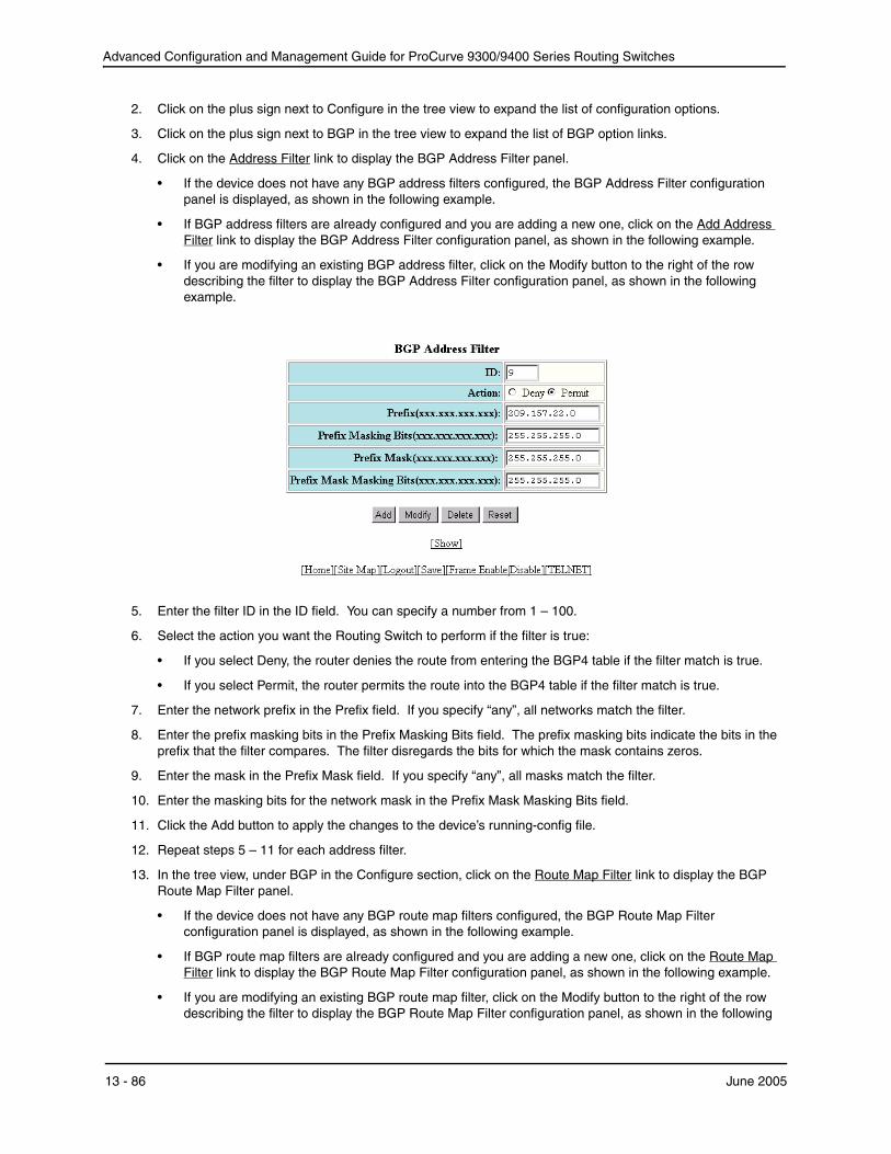
Advanced Configuration and Management Guide for ProCurve 9300/9400 Series Routing Switches
2. Click on the plus sign next to Configure in the tree view to expand the list of configuration options.
3. Click on the plus sign next to BGP in the tree view to expand the list of BGP option links.
4. Click on the Address Filter link to display the BGP Address Filter panel.
• If the device does not have any BGP address filters configured, the BGP Address Filter configuration panel is displayed, as shown in the following example.
• If BGP address filters are already configured and you are adding a new one, click on the Add Address Filter link to display the BGP Address Filter configuration panel, as shown in the following example.
• If you are modifying an existing BGP address filter, click on the Modify button to the right of the row describing the filter to display the BGP Address Filter configuration panel, as shown in the following example.
5. Enter the filter ID in the ID field. You can specify a number from 1 – 100.
6. Select the action you want the Routing Switch to perform if the filter is true:
• If you select Deny, the router denies the route from entering the BGP4 table if the filter match is true.
• If you select Permit, the router permits the route into the BGP4 table if the filter match is true.
7. Enter the network prefix in the Prefix field. If you specify “any”, all networks match the filter.
8. Enter the prefix masking bits in the Prefix Masking Bits field. The prefix masking bits indicate the bits in the prefix that the filter compares. The filter disregards the bits for which the mask contains zeros.
9. Enter the mask in the Prefix Mask field. If you specify “any”, all masks match the filter.
10. Enter the masking bits for the network mask in the Prefix Mask Masking Bits field.
11. Click the Add button to apply the changes to the device’s running-config file.
12. Repeat steps 5 – 11 for each address filter.
13. In the tree view, under BGP in the Configure section, click on the Route Map Filter link to display the BGP Route Map Filter panel.
• If the device does not have any BGP route map filters configured, the BGP Route Map Filter configuration panel is displayed, as shown in the following example.
• If BGP route map filters are already configured and you are adding a new one, click on the Route Map Filter link to display the BGP Route Map Filter configuration panel, as shown in the following example.
• If you are modifying an existing BGP route map filter, click on the Modify button to the right of the row describing the filter to display the BGP Route Map Filter configuration panel, as shown in the following
13 - 86 June 2005
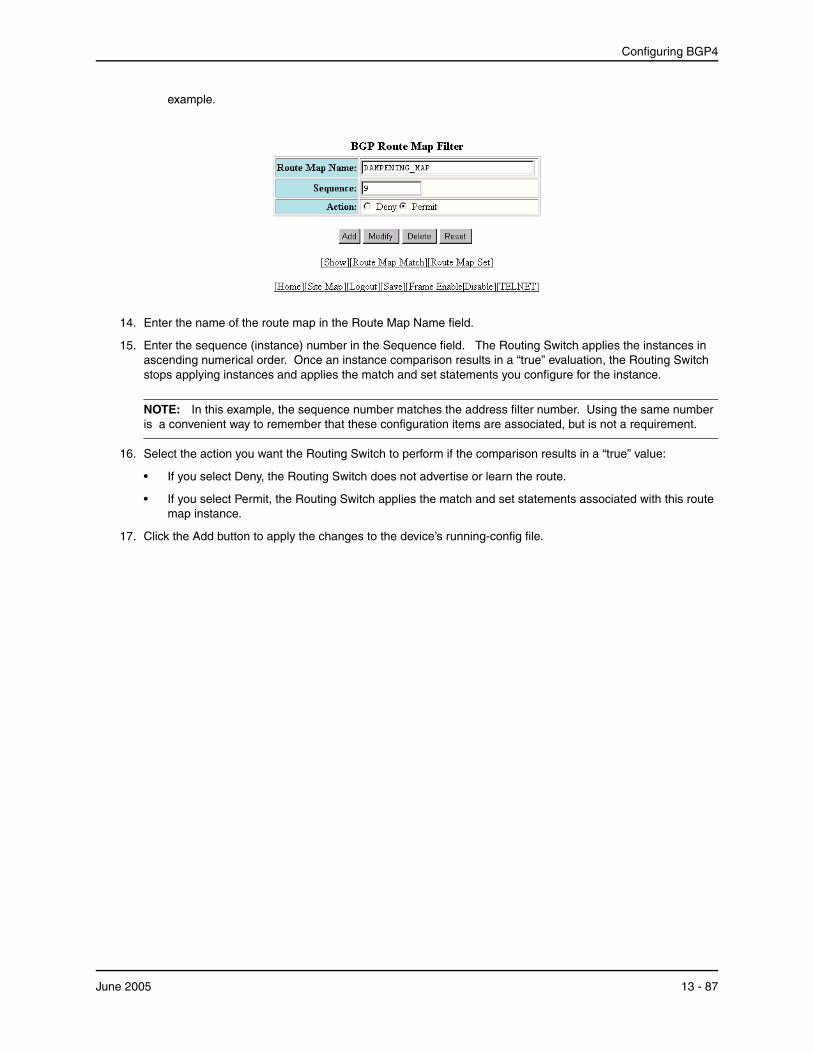
Configuring BGP4
example.
14. Enter the name of the route map in the Route Map Name field.
15. Enter the sequence (instance) number in the Sequence field. The Routing Switch applies the instances in ascending numerical order. Once an instance comparison results in a “true” evaluation, the Routing Switch stops applying instances and applies the match and set statements you configure for the instance.
NOTE: In this example, the sequence number matches the address filter number. Using the same number is a convenient way to remember that these configuration items are associated, but is not a requirement.
16. Select the action you want the Routing Switch to perform if the comparison results in a “true” value:
• If you select Deny, the Routing Switch does not advertise or learn the route.
• If you select Permit, the Routing Switch applies the match and set statements associated with this route map instance.
17. Click the Add button to apply the changes to the device’s running-config file.
June 2005 13 - 87

Advanced Configuration and Management Guide for ProCurve 9300/9400 Series Routing Switches
18. Select the Route Map Match link at the bottom of the panel to display the BGP Route Map Match panel, as shown in the following example.
19. Click on the checkbox next to Address Filter to indicate that you are using an address filter as a match condition.
20. Enter the address filter number in the Address Filter field.
21. Click Apply to apply the changes to the device’s running-config file.
13 - 88 June 2005
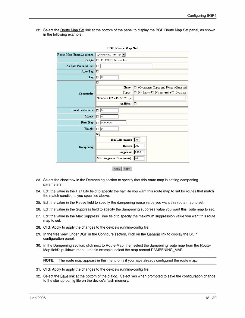
Configuring BGP4
22. Select the Route Map Set link at the bottom of the panel to display the BGP Route Map Set panel, as shown in the following example.
23. Select the checkbox in the Dampening section to specify that this route map is setting dampening parameters.
24. Edit the value in the Half Life field to specify the half life you want this route map to set for routes that match the match conditions you specified above.
25. Edit the value in the Reuse field to specify the dampening reuse value you want this route map to set.
26. Edit the value in the Suppress field to specify the dampening suppress value you want this route map to set.
27. Edit the value in the Max Suppress Time field to specify the maximum suppression value you want this route map to set.
28. Click Apply to apply the changes to the device’s running-config file.
29. In the tree view, under BGP in the Configure section, click on the General link to display the BGP configuration panel.
30. In the Dampening section, click next to Route-Map, then select the dampening route map from the Route-Map field’s pulldown menu. In this example, select the map named DAMPENING_MAP.
NOTE: The route map appears in this menu only if you have already configured the route map.
31. Click Apply to apply the changes to the device’s running-config file.
32. Select the Save link at the bottom of the dialog. Select Yes when prompted to save the configuration change to the startup-config file on the device’s flash memory.
June 2005 13 - 89

Advanced Configuration and Management Guide for ProCurve 9300/9400 Series Routing Switches
Using a Route Map To Configure Route Flap Dampening for a Specific Neighbor You can use a route map to configure route flap dampening for a specific neighbor by performing the following tasks:
• Configure an empty route map with no match or set statements. This route map does not specify particular routes for dampening but does allow you to enable dampening globally when you refer to this route map from within the BGP configuration level.
• Configure another route map that explicitly enables dampening. Use a set statement within the route map to enable dampening. When you associate this route map with a specific neighbor, the route map enables dampening for all routes associated with the neighbor. You also can use match statements within the route map to selectively perform dampening on some routes from the neighbor.
NOTE: You still need to configure the first route map to enable dampening globally. The second route map does not enable dampening by itself; it just applies dampening to a neighbor.
• Apply the route map to the neighbor.
USING THE CLI
To enable route flap dampening for a specific BGP4 neighbor, enter commands such as the following:
ProCurveRS(config)# route-map DAMPENING_MAP_ENABLE permit 1 ProCurveRS(config-routemap DAMPENING_MAP_ENABLE)# exit ProCurveRS(config)# route-map DAMPENING_MAP_NEIGHBOR_A permit 1 ProCurveRS(config-routemap DAMPENING_MAP_NEIGHBOR_A)# set dampening ProCurveRS(config-routemap DAMPENING_MAP_NEIGHBOR_A)# exit ProCurveRS(config)# router bgp ProCurveRS(config-bgp-router)# dampening route-map DAMPENING_MAP_ENABLE ProCurveRS(config-bgp-router)# neighbor 10.10.10.1 route-map in DAMPENING_MAP_NEIGHBOR_A
In this example, the first command globally enables route flap dampening. This route map does not contain any match or set statements. At the BGP configuration level, the dampening route-map command refers to the DAMPENING_MAP_ENABLE route map created by the first command, thus enabling dampening globally.
The third and fourth commands configure a second route map that explicitly enables dampening. Notice that the route map does not contain a match statement. The route map implicitly applies to all routes. Since the route map will be applied to a neighbor at the BGP configuration level, the route map will apply to all routes associated with the neighbor.
Although the second route map enables dampening, the first route map is still required. The second route map enables dampening for the neighbors to which the route map is applied. However, unless dampening is already enabled globally by the first route map, the second route map has no effect.
The last two commands apply the route maps. The dampening route-map command applies the first route map, which enables dampening globally. The neighbor command applies the second route map to neighbor 10.10.10.1. Since the second route map does not contain match statements for specific routes, the route map enables dampening for all routes received from the neighbor.
USING THE WEB MANAGEMENT INTERFACE
1. Log on to the device using a valid user name and password for read-write access. The System configuration panel is displayed.
2. Click on the plus sign next to Configure in the tree view to expand the list of configuration options.
3. Click on the plus sign next to BGP in the tree view to expand the list of BGP option links.
13 - 90 June 2005

Configuring BGP4
4. In the tree view, under BGP in the Configure section, click on the Route Map Filter link to display the BGP Route Map Filter panel.
NOTE: If the device already has route maps, a table listing the route maps is displayed. Click the Modify button to the right of the row describing the route map to change its configuration, or click the Add Route Map Filter link to display the BGP Route Map Filter panel.
5. Enter the name of the route map in the Route Map Name field. In this example, enter the name DAMPENING_MAP_ENABLE for the “empty” route map that you will use to globally enable dampening.
6. Enter the sequence (instance) number in the Sequence field or use the default value.
7. Select the action you want the Routing Switch to perform if the comparison results in a “true” value:
• If you select Deny, the Routing Switch does not advertise or learn the route.
• If you select Permit, the Routing Switch applies the match and set statements associated with this route map instance. In this example, select Permit.
8. Click the Add button to apply the changes to the device’s running-config file.
NOTE: In this case, you are configuring an “empty” route map with no match or set statements, so you do not need to select the Route Map Match or Route Map Set link.
9. Enter the name of the route map you will use to set dampening parameters for a neighbor in the Route Map Name field. In this example, enter the name DAMPENING_MAP_NEIGHBOR_A.
10. Select the action you want the Routing Switch to perform if the comparison results in a “true” value:
• If you select Deny, the Routing Switch does not advertise or learn the route.
• If you select Permit, the Routing Switch applies the match and set statements associated with this route map instance. In this example, select Permit.
11. Click the Add button to apply the changes to the device’s running-config file.
12. Select the Route Map Set link to display the BGP Route Map Set panel.
NOTE: If the interface displays a table listing the configured route maps, select the Route Map Set link under the table or click Modify next to the row describing the route map you are configuring.
13. Select the route map name and sequence from the Route Map Name.Sequence field’s pulldown menu.
14. Select the checkbox in the Dampening section to enable dampening for routes that match the route map.
15. Click the Apply button to apply the changes to the device’s running-config file.
16. In the tree view, under BGP in the Configure section, click on the General link to display the BGP configuration panel.
17. In the Dampening section, click next to Route-Map, then select the dampening route map from the Route-Map field’s pulldown menu. In this example, select the map named DAMPENING_MAP_ENABLE.
NOTE: The route map appears in this menu only if you have already configured the route map.
18. Click Apply to apply the changes to the device’s running-config file.
19. In the tree view, under BGP in the Configure section, click on the Neighbor link to display the list of BGP neighbors.
20. Select the Modify button to the right of the row describing the neighbor to which you want to apply the dampening route map you configured in steps 9 – 15.
June 2005 13 - 91
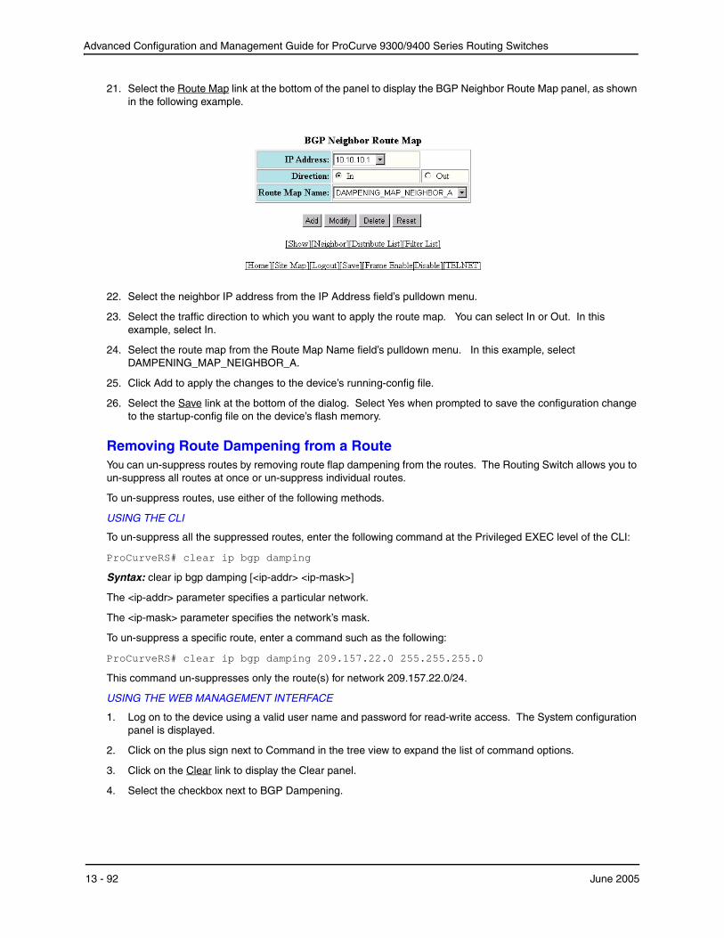
Advanced Configuration and Management Guide for ProCurve 9300/9400 Series Routing Switches
21. Select the Route Map link at the bottom of the panel to display the BGP Neighbor Route Map panel, as shown in the following example.
22. Select the neighbor IP address from the IP Address field’s pulldown menu.
23. Select the traffic direction to which you want to apply the route map. You can select In or Out. In this example, select In.
24. Select the route map from the Route Map Name field’s pulldown menu. In this example, select DAMPENING_MAP_NEIGHBOR_A.
25. Click Add to apply the changes to the device’s running-config file.
26. Select the Save link at the bottom of the dialog. Select Yes when prompted to save the configuration change to the startup-config file on the device’s flash memory.
Removing Route Dampening from a Route You can un-suppress routes by removing route flap dampening from the routes. The Routing Switch allows you to un-suppress all routes at once or un-suppress individual routes.
To un-suppress routes, use either of the following methods.
USING THE CLI
To un-suppress all the suppressed routes, enter the following command at the Privileged EXEC level of the CLI:
ProCurveRS# clear ip bgp damping
Syntax: clear ip bgp damping [<ip-addr> <ip-mask>]
The <ip-addr> parameter specifies a particular network.
The <ip-mask> parameter specifies the network’s mask.
To un-suppress a specific route, enter a command such as the following:
ProCurveRS# clear ip bgp damping 209.157.22.0 255.255.255.0
This command un-suppresses only the route(s) for network 209.157.22.0/24.
USING THE WEB MANAGEMENT INTERFACE
1. Log on to the device using a valid user name and password for read-write access. The System configuration panel is displayed.
2. Click on the plus sign next to Command in the tree view to expand the list of command options.
3. Click on the Clear link to display the Clear panel.
4. Select the checkbox next to BGP Dampening.
13 - 92 June 2005

Configuring BGP4
5. Specify the routes from which you want to remove dampening:
• To clear dampening for all routes, select the All option.
• To clear dampening for a specific route, select IP, then enter the network address and sub-net mask in the IP and Mask fields.
6. Click the Apply button to implement the change.
Removing Route Dampening from a Neighbor’s Routes Suppressed Due to Aggregation You can selectively unsuppress more-specific routes that have been suppressed due to aggregation, and allow the routes to be advertised to a specific neighbor or peer group.
Here is an example.
ProCurveRS(config-bgp-router)# aggregate-address 209.1.0.0 255.255.0.0 summaryonlyProCurveRS(config-bgp-router)# show ip bgp route 209.1.0.0/16 longerNumber of BGP Routes matching display condition : 2 Status A:AGGREGATE B:BEST b:NOT-INSTALLED-BEST C:CONFED_EBGP D:DAMPED
E:EBGP H:HISTORY I:IBGP L:LOCAL M:MULTIPATH S:SUPPRESSED F:FILTERED Prefix Next Hop Metric LocPrf Weight Status
1 209.1.0.0/16 0.0.0.0 101 32768 BAL AS_PATH:
2 209.1.44.0/24 10.2.0.1 1 101 32768 BLS
The aggregate-address command configures an aggregate address. The summary-only parameter prevents the Routing Switch from advertising more specific routes contained within the aggregate route. The show ip bgp route command shows that the more specific routes aggregated into 209.1.0.0/16 have been suppressed. In this case, the route to 209.1.44.0/24 has been suppressed. The following command indicates that the route is not being advertised to the Routing Switch’s BGP4 neighbors.
ProCurveRS(config-bgp-router)# show ip bgp route 209.1.44.0/24Number of BGP Routes matching display condition : 1 Status A:AGGREGATE B:BEST b:NOT-INSTALLED-BEST C:CONFED_EBGP D:DAMPED
E:EBGP H:HISTORY I:IBGP L:LOCAL M:MULTIPATH S:SUPPRESSED F:FILTERED Prefix Next Hop Metric LocPrf Weight Status
1 209.1.44.0/24 10.2.0.1 1 101 32768 BLS AS_PATH: Route is not advertised to any peers
If you want to override the summary-only parameter and allow a specific route to be advertised to a neighbor, enter commands such as the following:
ProCurveRS(config)# ip prefix-list Unsuppress1 permit 209.1.44.0/24ProCurveRS(config)# route-map RouteMap1 permit 1ProCurveRS(config-routemap RouteMap1)# match prefix-list Unsuppress1ProCurveRS(config-routemap RouteMap1)# exitProCurveRS(config)# router bgpProCurveRS(config-bgp-router)# neighbor 10.1.0.2 unsuppress-map RouteMap1ProCurveRS(config-bgp-router)# clear ip bgp neighbor 10.1.0.2 soft-out
The ip prefix-list command configures an IP prefix list for network 209.1.44.0/24, which is the route you want to unsuppress. The next two commands configure a route map that uses the prefix list as input. The neighbor command enables the Routing Switch to advertise the routes specified in the route map to neighbor 10.1.0.2. The
June 2005 13 - 93
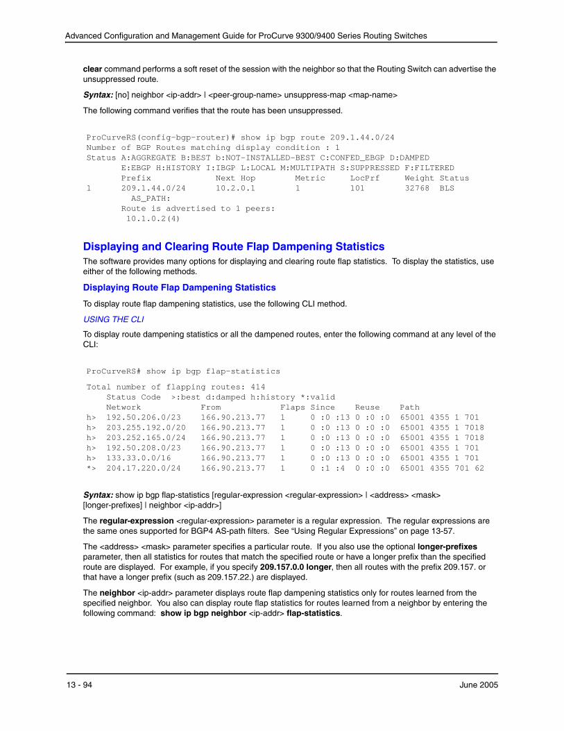
Advanced Configuration and Management Guide for ProCurve 9300/9400 Series Routing Switches
clear command performs a soft reset of the session with the neighbor so that the Routing Switch can advertise the unsuppressed route.
Syntax: [no] neighbor <ip-addr> | <peer-group-name> unsuppress-map <map-name>
The following command verifies that the route has been unsuppressed.
ProCurveRS(config-bgp-router)# show ip bgp route 209.1.44.0/24 Number of BGP Routes matching display condition : 1 Status A:AGGREGATE B:BEST b:NOT-INSTALLED-BEST C:CONFED_EBGP D:DAMPED
E:EBGP H:HISTORY I:IBGP L:LOCAL M:MULTIPATH S:SUPPRESSED F:FILTERED Prefix Next Hop Metric LocPrf Weight Status
1 209.1.44.0/24 10.2.0.1 1 101 32768 BLS AS_PATH: Route is advertised to 1 peers: 10.1.0.2(4)
Displaying and Clearing Route Flap Dampening Statistics The software provides many options for displaying and clearing route flap statistics. To display the statistics, use either of the following methods.
Displaying Route Flap Dampening Statistics
To display route flap dampening statistics, use the following CLI method.
USING THE CLI
To display route dampening statistics or all the dampened routes, enter the following command at any level of the CLI:
ProCurveRS# show ip bgp flap-statistics
Total number of flapping routes: 414 Status Code >:best d:damped h:history *:valid Network From Flaps Since Reuse Path
h> 192.50.206.0/23 166.90.213.77 1 0 :0 :13 0 :0 :0 65001 4355 1 701h> 203.255.192.0/20 166.90.213.77 1 0 :0 :13 0 :0 :0 65001 4355 1 7018 h> 203.252.165.0/24 166.90.213.77 1 0 :0 :13 0 :0 :0 65001 4355 1 7018 h> 192.50.208.0/23 166.90.213.77 1 0 :0 :13 0 :0 :0 65001 4355 1 701 h> 133.33.0.0/16 166.90.213.77 1 0 :0 :13 0 :0 :0 65001 4355 1 701 *> 204.17.220.0/24 166.90.213.77 1 0 :1 :4 0 :0 :0 65001 4355 701 62
Syntax: show ip bgp flap-statistics [regular-expression <regular-expression> | <address> <mask> [longer-prefixes] | neighbor <ip-addr>]
The regular-expression <regular-expression> parameter is a regular expression. The regular expressions are the same ones supported for BGP4 AS-path filters. See “Using Regular Expressions” on page 13-57.
The <address> <mask> parameter specifies a particular route. If you also use the optional longer-prefixes parameter, then all statistics for routes that match the specified route or have a longer prefix than the specified route are displayed. For example, if you specify 209.157.0.0 longer, then all routes with the prefix 209.157. or that have a longer prefix (such as 209.157.22.) are displayed.
The neighbor <ip-addr> parameter displays route flap dampening statistics only for routes learned from the specified neighbor. You also can display route flap statistics for routes learned from a neighbor by entering the following command: show ip bgp neighbor <ip-addr> flap-statistics.
13 - 94 June 2005

Configuring BGP4
This display shows the following information.
Table 13.3: Route Flap Dampening Statistics
This Field...
Total number of flapping routes
Status code
Network
From
Flaps
Since
Reuse
Path
Displays...
The total number of routes in the Routing Switch’s BGP4 route table that have changed state and thus have been marked as flapping routes.
Indicates the dampening status of the route, which can be one of the following:
• > – This is the best route among those in the BGP4 route table to the route’s destination.
• d – This route is currently dampened, and thus unusable.
• h – The route has a history of flapping and is unreachable now.
• * – The route has a history of flapping but is currently usable.
The destination network of the route.
The neighbor that sent the route to the Routing Switch.
The number of flaps (state changes) the route has experienced.
The amount of time since the first flap of this route.
The amount of time remaining until this route will be un-suppressed and thus be usable again.
Shows the AS-path information for the route.
You also can display all the dampened routes by entering the following command: show ip bgp dampened-paths.
USING THE WEB MANAGEMENT INTERFACE
You cannot display dampening statistics using the Web management interface.
Clearing Route Flap Dampening Statistics
To clear route flap dampening statistics, use the following CLI method.
NOTE: Clearing the dampening statistics for a route does not change the dampening status of the route.
USING THE CLI
To clear all the route dampening statistics, enter the following command at any level of the CLI:
ProCurveRS# clear ip bgp flap-statistics
Syntax: clear ip bgp flap-statistics [regular-expression <regular-expression> | <address> <mask> | neighbor <ipaddr>]
The parameters are the same as those for the show ip bgp flap-statistics command (except the longerprefixes option is not supported). See “Displaying Route Flap Dampening Statistics” on page 13-94.
NOTE: The clear ip bgp damping command not only clears statistics but also un-suppresses the routes. See “Displaying Route Flap Dampening Statistics” on page 13-94.
June 2005 13 - 95
Advanced Configuration and Management Guide for ProCurve 9300/9400 Series Routing Switches
USING THE WEB MANAGEMENT INTERFACE
You cannot clear dampening statistics using the Web management interface.
Generating Traps for BGP Software release 07.7.00 provides the ability to enable and disable SNMP traps for BGP. BGP traps are enabled by default.
To enable BGP traps after they have been disabled, enter the following command:
ProCurveRS(config)# snmp-server enable traps bgp
Syntax: [no] snmp-server enable traps bgp
Use the no form of the command to disable BGP traps.
Displaying BGP4 Information You can display the following configuration information and statistics for the BGP4 protocol on the router:
• Summary BGP4 configuration information for the router
• Active BGP4 configuration information (the BGP4 information in the running-config)
• CPU utilization statistics
• Neighbor information
• Peer-group information
• Information about the paths from which BGP4 selects routes
• Summary BGP4 route information
• The router’s BGP4 route table
• Route flap dampening statistics
• Active route maps (the route map configuration information in the running-config)
Displaying Summary BGP4 Information You can display the local AS number, the maximum number of routes and neighbors supported, and some BGP4 statistics using either of the following methods.
13 - 96 June 2005

Configuring BGP4
USING THE CLI
To view summary BGP4 information for the router, enter the following command at any CLI prompt:
ProCurveRS# show ip bgp summary BGP4 Summary Router ID: 101.0.0.1 Local AS Number : 4 Confederation Identifier : not configured Confederation Peers: 4 5 Maximum Number of Paths Supported for Load Sharing : 1 Number of Neighbors Configured : 11 Number of Routes Installed : 2 Number of Routes Advertising to All Neighbors : 8 Number of Attribute Entries Installed : 6 Neighbor Address 1.2.3.4
AS# 200
State ADMDN
Time Rt:Accepted Filtered Sent 0h44m56s 0 0 0
ToSend 2
10.0.0.2 5 ADMDN 0h44m56s 0 0 0 0 10.1.0.2 5 ESTAB 0h44m56s 1 11 0 0 10.2.0.2 5 ESTAB 0h44m55s 1 0 0 0 10.3.0.2 5 ADMDN 0h25m28s 0 0 0 0 10.4.0.2 5 ADMDN 0h25m31s 0 0 0 0 10.5.0.2 5 CONN 0h 0m 8s 0 0 0 0 10.7.0.2 5 ADMDN 0h44m56s 0 0 0 0 100.0.0.1 4 ADMDN 0h44m56s 0 0 0 2 102.0.0.1 4 ADMDN 0h44m56s 0 0 0 2 150.150.150.150 0 ADMDN 0h44m56s 0 0 0 2
This display shows the following information.
Table 13.4: BGP4 Summary Information
This Field...
Router ID
Local AS Number
Confederation Identifier
Confederation Peers
Maximum Number of Paths Supported for Load Sharing
Number of Neighbors Configured The number of BGP4 neighbors configured on this Routing Switch.
Number of Routes Installed The number of BGP4 routes in the router’s BGP4 route table.
To display the BGP4 route table, see “Displaying the BGP4 Route Table” on page 13-120.
Number of Routes Advertising to All Neighbors
Displays...
The Routing Switch’s router ID.
The BGP4 AS number the router is in.
The AS number of the confederation the Routing Switch is in.
The numbers of the local ASs contained in the confederation. This list matches the confederation peer list you configure on the Routing Switch.
The maximum number of route paths across which the device can balance traffic to the same destination. The feature is enabled by default but the default number of paths is 1. You can increase the number from 2 – 8 paths. See “Changing the Maximum Number of Paths for BGP4 Load Sharing” on page 13-27.
The total of the RtSent and RtToSend columns for all neighbors.
June 2005 13 - 97

Advanced Configuration and Management Guide for ProCurve 9300/9400 Series Routing Switches
Table 13.4: BGP4 Summary Information (Continued)
This Field...
Number of Attribute Entries Installed
Neighbor Address
AS#
State
Time
Displays...
The number of BGP4 route-attribute entries in the router’s routeattributes table. To display the route-attribute table, see “Displaying BGP4 Route-Attribute Entries” on page 13-128.
The IP addresses of this router’s BGP4 neighbors.
The AS number.
The state of this router’s neighbor session with each neighbor. The states are from this router’s perspective of the session, not the neighbor’s perspective. The state values are based on the BGP4 state machine values described in RFC 1771 and can be one of the following for each router:
• IDLE – The BGP4 process is waiting to be started. Usually, enabling BGP4 or establishing a neighbor session starts the BGP4 process.
• A minus sign (-) indicates that the session has gone down and the software is clearing or removing routes.
• ADMND – The neighbor has been administratively shut down. See “Administratively Shutting Down a Session with a BGP4 Neighbor” on page 13-25.
• A minus sign (-) indicates that the session has gone down and the software is clearing or removing routes.
• CONNECT – BGP4 is waiting for the connection process for the TCP neighbor session to be completed.
• ACTIVE – BGP4 is waiting for a TCP connection from the neighbor.
Note: If the state frequently changes between CONNECT and ACTIVE, there may be a problem with the TCP connection.
• OPEN SENT – BGP4 is waiting for an Open message from the neighbor.
• OPEN CONFIRM – BGP4 has received an OPEN message from the neighbor and is now waiting for either a KEEPALIVE or NOTIFICATION message. If the router receives a KEEPALIVE message from the neighbor, the state changes to Established. If the message is a NOTIFICATION, the state changes to Idle.
• ESTABLISHED – BGP4 is ready to exchange UPDATE packets with the neighbor.
• If there is more BGP data in the TCP receiver queue, a plus sign (+) is also displayed.
Note: If you display information for the neighbor using the show ip bgp neighbor <ip-addr> command, the TCP receiver queue value will be greater than 0.
The time that has passed since the state last changed.
13 - 98 June 2005

Configuring BGP4
Table 13.4: BGP4 Summary Information (Continued)
This Field...
Accepted
Filtered
Sent
ToSend
Displays...
The number of routes received from the neighbor that this router installed in the BGP4 route table. Usually, this number is lower than the RoutesRcvd number. The difference indicates that this router filtered out some of the routes received in the UPDATE messages.
The routes or prefixes that have been filtered out.
• If soft reconfiguration is enabled, this field shows how many routes were filtered out (not placed in the BGP4 route table) but retained in memory.
• If soft reconfiguration is not enabled, this field shows the number of BGP4 routes that have been filtered out.
The number of BGP4 routes that the Routing Switch has sent to the neighbor.
The number of routes the Routing Switch has queued to send to this neighbor.
USING THE WEB MANAGEMENT INTERFACE
1. Log on to the device using a valid user name and password for read-only or read-write access. The System configuration panel is displayed.
2. Click on the plus sign next to Monitor in the tree view to expand the list of monitoring options.
3. Click on the plus sign next to BGP in the tree view to expand the list of BGP option links.
4. Click on the Summary link to display the BGP Neighbor Summary panel.
Displaying the Active BGP4 Configuration To view the active BGP4 configuration information contained in the running-config without displaying the entire running-config, use the following CLI method.
June 2005 13 - 99
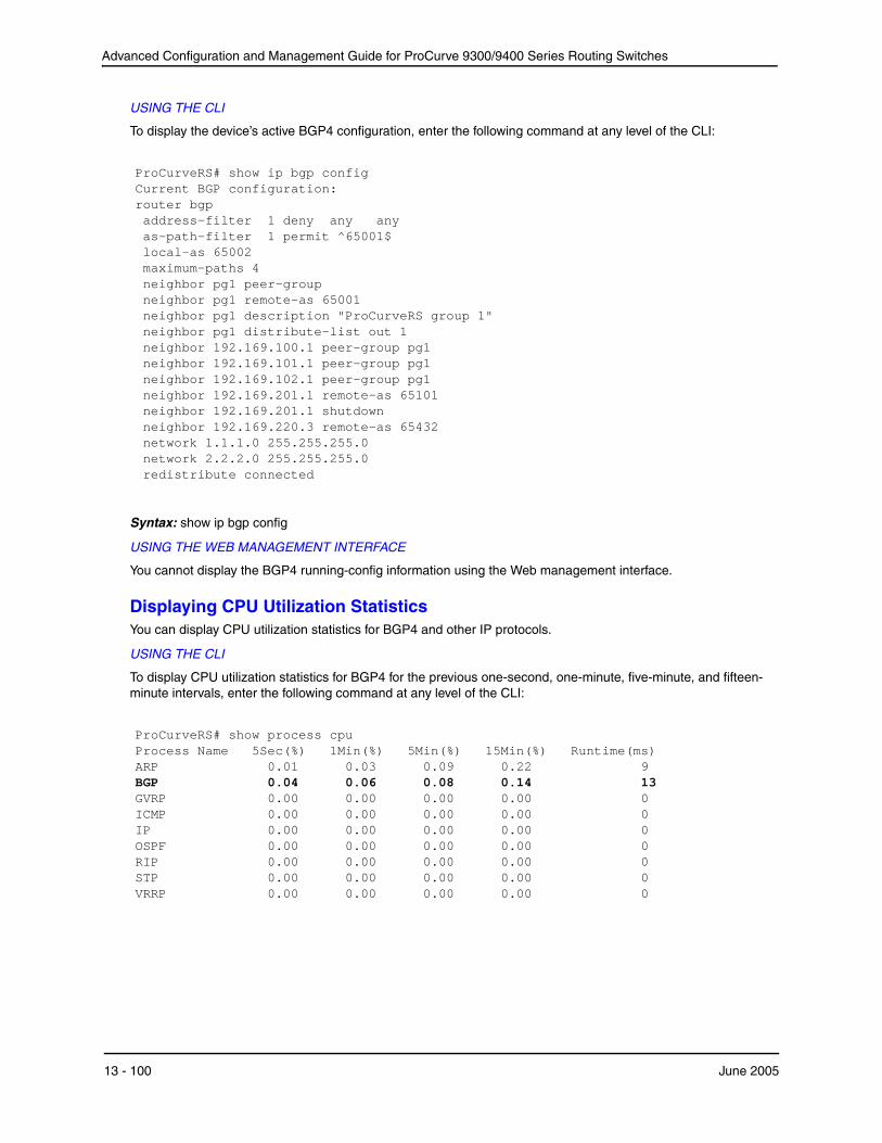
Advanced Configuration and Management Guide for ProCurve 9300/9400 Series Routing Switches
USING THE CLI
To display the device’s active BGP4 configuration, enter the following command at any level of the CLI:
ProCurveRS# show ip bgp configCurrent BGP configuration: router bgp address-filter 1 deny any anyas-path-filter 1 permit ^65001$ local-as 65002 maximum-paths 4 neighbor pg1 peer-group neighbor pg1 remote-as 65001 neighbor pg1 description "ProCurveRS group 1" neighbor pg1 distribute-list out 1 neighbor 192.169.100.1 peer-group pg1 neighbor 192.169.101.1 peer-group pg1 neighbor 192.169.102.1 peer-group pg1 neighbor 192.169.201.1 remote-as 65101neighbor 192.169.201.1 shutdown neighbor 192.169.220.3 remote-as 65432network 1.1.1.0 255.255.255.0network 2.2.2.0 255.255.255.0redistribute connected
Syntax: show ip bgp config
USING THE WEB MANAGEMENT INTERFACE
You cannot display the BGP4 running-config information using the Web management interface.
Displaying CPU Utilization Statistics You can display CPU utilization statistics for BGP4 and other IP protocols.
USING THE CLI
To display CPU utilization statistics for BGP4 for the previous one-second, one-minute, five-minute, and fifteenminute intervals, enter the following command at any level of the CLI:
ProCurveRS# show process cpu Process NameARP
5Sec(%)0.01
1Min(%) 0.03
5Min(%) 0.09
15Min(%)0.22
Runtime(ms) 9
BGP 0.04 0.06 0.08 0.14 13 GVRP 0.00 0.00 0.00 0.00 0 ICMP 0.00 0.00 0.00 0.00 0 IP 0.00 0.00 0.00 0.00 0 OSPF 0.00 0.00 0.00 0.00 0 RIP 0.00 0.00 0.00 0.00 0 STP 0.00 0.00 0.00 0.00 0 VRRP 0.00 0.00 0.00 0.00 0
13 - 100 June 2005

Configuring BGP4
If the software has been running less than 15 minutes (the maximum interval for utilization statistics), the command indicates how long the software has been running. Here is an example:
ProCurveRS# show process cpu The system has only been up for 6 seconds. Process NameARP
5Sec(%)0.01
1Min(%) 0.00
5Min(%) 0.00
15Min(%)0.00
Runtime(ms) 0
BGP 0.00 0.00 0.00 0.00 0 GVRP 0.00 0.00 0.00 0.00 0 ICMP 0.01 0.00 0.00 0.00 1 IP 0.00 0.00 0.00 0.00 0 OSPF 0.00 0.00 0.00 0.00 0 RIP 0.00 0.00 0.00 0.00 0 STP 0.00 0.00 0.00 0.00 0 VRRP 0.00 0.00 0.00 0.00 0
To display utilization statistics for a specific number of seconds, enter a command such as the following:
ProCurveRS# show process cpu 2 Statistics for last 1 sec and 80 ms Process Name Sec(%) Time(ms) ARP 0.00 0 BGP 0.00 0 GVRP 0.00 0 ICMP 0.01 1 IP 0.00 0 OSPF 0.00 0 RIP 0.00 0 STP 0.01 0 VRRP 0.00 0
When you specify how many seconds’ worth of statistics you want to display, the software selects the sample that most closely matches the number of seconds you specified. In this example, statistics are requested for the previous two seconds. The closest sample available is actually for the previous 1 second plus 80 milliseconds.
Syntax: show process cpu [<num>]
The <num> parameter specifies the number of seconds and can be from 1 – 900. If you use this parameter, the command lists the usage statistics only for the specified number of seconds. If you do not use this parameter, the command lists the usage statistics for the previous one-second, one-minute, five-minute, and fifteen-minute intervals.
USING THE WEB MANAGEMENT INTERFACE
You cannot display this information using the Web management interface.
Displaying Summary Neighbor Information To display information for a neighbor, use the following CLI method.
June 2005 13 - 101

Advanced Configuration and Management Guide for ProCurve 9300/9400 Series Routing Switches
1
USING THE CLI
To display summary neighbor information, enter a command such as the following at any level of the CLI:
ProCurveRS(config-bgp-router)# show ip bgp neighbor 192.168.4.211 routes-summary IP Address: 192.168.4.211
Routes Accepted/Installed:1, Filtered/Kept:11, Filtered:11 Routes Selected as BEST Routes:1
BEST Routes not Installed in IP Forwarding Table:0 Unreachable Routes (no IGP Route for NEXTHOP):0 History Routes:0
NLRIs Received in Update Message:24, Withdraws:0 (0), Replacements:1 NLRIs Discarded due to
Maximum Prefix Limit:0, AS Loop:0Invalid Nexthop:0, Invalid Nexthop Address:0.0.0.0 Duplicated Originator_ID:0, Cluster_ID:0
Routes Advertised:0, To be Sent:0, To be Withdrawn:0 NLRIs Sent in Update Message:0, Withdraws:0, Replacements:0
Peer Out of Memory Count for: Receiving Update Messages:0, Accepting Routes(NLRI):0 Attributes:0, Outbound Routes(RIB-out):0
Syntax: show ip bgp neighbors [<ip-addr>] | [route-summary]
This display shows the following information.
Table 13.5: BGP4 Route Summary Information for a Neighbor
This Field...
IP Address
Routes Received
Routes Selected as BEST Routes
BEST Routes not Installed in IP Forwarding Table
Unreachable Routes
Displays...
The IP address of the neighbor
How many routes the Routing Switch has received from the neighbor during the current BGP4 session.
• Accepted/Installed – Indicates how many of the received routes the Routing Switch accepted and installed in the BGP4 route table.
• Filtered/Kept – Indicates how many routes were filtered out, but were nonetheless retained in memory for use by the soft reconfiguration feature.
• Filtered – Indicates how many of the received routes were filtered out.
The number of routes that the Routing Switch selected as the best routes to their destinations.
The number of routes received from the neighbor that are the best BGP4 routes to their destinations, but were nonetheless not installed in the IP route table because the Routing Switch received better routes from other sources (such as OSPF, RIP, or static IP routes).
The number of routes received from the neighbor that are unreachable because the Routing Switch does not have a valid RIP, OSPF, or static route to the next hop.
13 - 102 June 2005
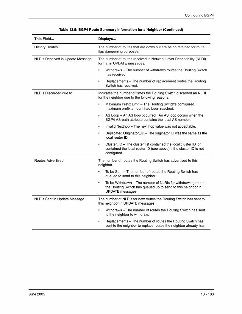
Configuring BGP4
Table 13.5: BGP4 Route Summary Information for a Neighbor (Continued)
This Field...
History Routes
NLRIs Received in Update Message
NLRIs Discarded due to
Routes Advertised
NLRIs Sent in Update Message
Displays...
The number of routes that are down but are being retained for route flap dampening purposes.
The number of routes received in Network Layer Reachability (NLRI) format in UPDATE messages.
• Withdraws – The number of withdrawn routes the Routing Switch has received.
• Replacements – The number of replacement routes the Routing Switch has received.
Indicates the number of times the Routing Switch discarded an NLRI for the neighbor due to the following reasons:
• Maximum Prefix Limit – The Routing Switch’s configured maximum prefix amount had been reached.
• AS Loop – An AS loop occurred. An AS loop occurs when the BGP4 AS-path attribute contains the local AS number.
• Invalid Nexthop – The next hop value was not acceptable.
• Duplicated Originator_ID – The originator ID was the same as the local router ID.
• Cluster_ID – The cluster list contained the local cluster ID, or contained the local router ID (see above) if the cluster ID is not configured.
The number of routes the Routing Switch has advertised to this neighbor.
• To be Sent – The number of routes the Routing Switch has queued to send to this neighbor.
• To be Withdrawn – The number of NLRIs for withdrawing routes the Routing Switch has queued up to send to this neighbor in UPDATE messages.
The number of NLRIs for new routes the Routing Switch has sent to this neighbor in UPDATE messages.
• Withdraws – The number of routes the Routing Switch has sent to the neighbor to withdraw.
• Replacements – The number of routes the Routing Switch has sent to the neighbor to replace routes the neighbor already has.
June 2005 13 - 103
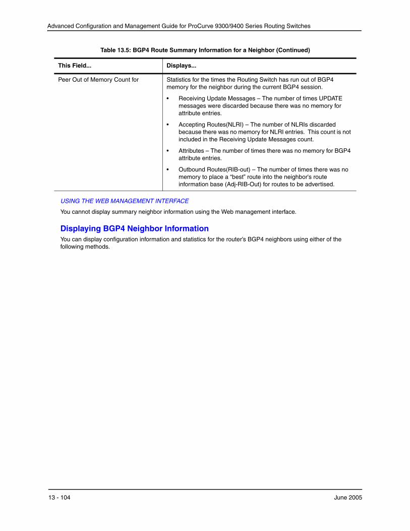
Advanced Configuration and Management Guide for ProCurve 9300/9400 Series Routing Switches
Table 13.5: BGP4 Route Summary Information for a Neighbor (Continued)
This Field... Displays...
Peer Out of Memory Count for Statistics for the times the Routing Switch has run out of BGP4 memory for the neighbor during the current BGP4 session.
• Receiving Update Messages – The number of times UPDATE messages were discarded because there was no memory for attribute entries.
• Accepting Routes(NLRI) – The number of NLRIs discarded because there was no memory for NLRI entries. This count is not included in the Receiving Update Messages count.
• Attributes – The number of times there was no memory for BGP4 attribute entries.
• Outbound Routes(RIB-out) – The number of times there was no memory to place a “best” route into the neighbor's route information base (Adj-RIB-Out) for routes to be advertised.
USING THE WEB MANAGEMENT INTERFACE
You cannot display summary neighbor information using the Web management interface.
Displaying BGP4 Neighbor Information You can display configuration information and statistics for the router’s BGP4 neighbors using either of the following methods.
13 - 104 June 2005
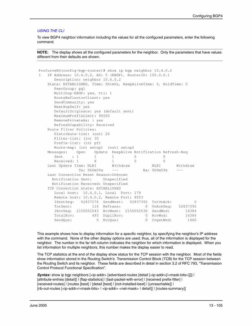
Configuring BGP4
---
1
USING THE CLI
To view BGP4 neighbor information including the values for all the configured parameters, enter the following command.
NOTE: The display shows all the configured parameters for the neighbor. Only the parameters that have values different from their defaults are shown.
ProCurveRS(config-bgp-router)# show ip bgp neighbor 10.4.0.2 IP Address: 10.4.0.2, AS: 5 (EBGP), RouterID: 100.0.0.1 Description: neighbor 10.4.0.2
State: ESTABLISHED, Time: 0h1m0s, KeepAliveTime: 0, HoldTime: 0 PeerGroup: pg1 Multihop-EBGP: yes, ttl: 1 RouteReflectorClient: yes SendCommunity: yes NextHopSelf: yes DefaultOriginate: yes (default sent) MaximumPrefixLimit: 90000 RemovePrivateAs: : yes RefreshCapability: Received
Route Filter Policies: Distribute-list: (out) 20 Filter-list: (in) 30 Prefix-list: (in) pf1 Route-map: (in) setnp1 (out) setnp2
Messages: Open Update KeepAlive Notification Refresh-Req Sent : 1 1 1 0 0
Received: 1 8 1 0 0 Last Update Time: NLRI
Tx: 0h0m59s Withdraw
---NLRI
Rx: 0h0m59s Withdraw
Last Connection Reset Reason:Unknown Notification Sent: Unspecified Notification Received: Unspecified
TCP Connection state: ESTABLISHED Local host: 10.4.0.1, Local Port: 179 Remote host: 10.4.0.2, Remote Port: 8053 ISentSeq: 52837276 SendNext: 52837392 TotSent: 116 ReTrans: 0 IRcvSeq: 2155052043 RcvNext: 2155052536 TotalRcv: 493 DupliRcv: 0 SendQue: 0 RcvQue: 0
TotUnAck: UnAckSeq: SendWnd: RcvWnd: CngstWnd:
052837392
16384 16384 1460
This example shows how to display information for a specific neighbor, by specifying the neighbor’s IP address with the command. None of the other display options are used; thus, all of the information is displayed for the neighbor. The number in the far left column indicates the neighbor for which information is displayed. When you list information for multiple neighbors, this number makes the display easier to read.
The TCP statistics at the end of the display show status for the TCP session with the neighbor. Most of the fields show information stored in the Routing Switch’s Transmission Control Block (TCB) for the TCP session between the Routing Switch and its neighbor. These fields are described in detail in section 3.2 of RFC 793, “Transmission Control Protocol Functional Specification”.
Syntax: show ip bgp neighbors [<ip-addr> [advertised-routes [detail [<ip-addr>[/<mask-bits>]]]] | [attribute-entries [detail]] | [flap-statistics] | [last-packet-with-error] | [received prefix-filter] | [received-routes] | [routes [best] | [detail [best] | [not-installed-best] | [unreachable]] | [rib-out-routes [<ip-addr>/<mask-bits> | <ip-addr> <net-mask> | detail]] | [routes-summary]]
June 2005 13 - 105

Advanced Configuration and Management Guide for ProCurve 9300/9400 Series Routing Switches
The <ip-addr> option lets you narrow the scope of the command to a specific neighbor.
The advertised-routes option displays only the routes that the Routing Switch has advertised to the neighbor during the current BGP4 neighbor session.
The attribute-entries option shows the attribute-entries associated with routes received from the neighbor.
The flap-statistics option shows the route flap statistics for routes received from or sent to the neighbor.
The last-packet-with-error option displays the last packet from the neighbor that contained an error. The packet's contents are displayed in decoded (human-readable) format.
The received prefix-filter option shows the Outbound Route Filters (ORFs) received from the neighbor. This option applies to cooperative route filtering.
The received-routes option lists all the route information received in route updates from the neighbor since the soft reconfiguration feature was enabled. See “Using Soft Reconfiguration” on page 13-133.
The routes option lists the routes received in UPDATE messages from the neighbor. You can specify the following additional options:
• best – Displays the routes received from the neighbor that the Routing Switch selected as the best routes to their destinations.
• not-installed-best – Displays the routes received from the neighbor that are the best BGP4 routes to their destinations, but were nonetheless not installed in the IP route table because the Routing Switch received better routes from other sources (such as OSPF, RIP, or static IP routes).
• unreachable – Displays the routes that are unreachable because the Routing Switch does not have a valid RIP, OSPF, or static route to the next hop.
• detail – Displays detailed information for the specified routes. You can refine your information request by also specifying one of the options above (best, not-installed-best, or unreachable).
The rib-out-routes option lists the route information base (RIB) for outbound routes. You can display all the routes or specify a network address.
The routes-summary option displays a summary of the following information:
• Number of routes received from the neighbor
• Number of routes accepted by this Routing Switch from the neighbor
• Number of routes this Routing Switch filtered out of the UPDATES received from the neighbor and did not accept
• Number of routes advertised to the neighbor
• Number of attribute entries associated with routes received from or advertised to the neighbor.
This display shows the following information.
Table 13.6: BGP4 Neighbor Information
This Field... Displays...
IP Address The IP address of the neighbor.
AS The AS the neighbor is in.
13 - 106 June 2005
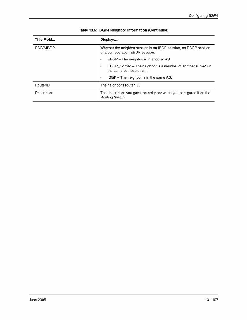
Configuring BGP4
Table 13.6: BGP4 Neighbor Information (Continued)
This Field...
EBGP/IBGP
RouterID
Description
Displays...
Whether the neighbor session is an IBGP session, an EBGP session, or a confederation EBGP session.
• EBGP – The neighbor is in another AS.
• EBGP_Confed – The neighbor is a member of another sub-AS in the same confederation.
• IBGP – The neighbor is in the same AS.
The neighbor’s router ID.
The description you gave the neighbor when you configured it on the Routing Switch.
June 2005 13 - 107

Advanced Configuration and Management Guide for ProCurve 9300/9400 Series Routing Switches
Table 13.6: BGP4 Neighbor Information (Continued)
This Field...
State
Time
KeepAliveTime
HoldTime
PeerGroup
Displays...
The state of the router’s session with the neighbor. The states are from this router’s perspective of the session, not the neighbor’s perspective. The state values are based on the BGP4 state machine values described in RFC 1771 and can be one of the following for each router:
• IDLE – The BGP4 process is waiting to be started. Usually, enabling BGP4 or establishing a neighbor session starts the BGP4 process.
• A minus sign (-) indicates that the session has gone down and the software is clearing or removing routes.
• ADMND – The neighbor has been administratively shut down. See “Administratively Shutting Down a Session with a BGP4 Neighbor” on page 13-25.
• A minus sign (-) indicates that the session has gone down and the software is clearing or removing routes.
• CONNECT – BGP4 is waiting for the connection process for the TCP neighbor session to be completed.
• ACTIVE – BGP4 is waiting for a TCP connection from the neighbor.
Note: If the state frequently changes between CONNECT and ACTIVE, there may be a problem with the TCP connection.
• OPEN SENT – BGP4 is waiting for an Open message from the neighbor.
• OPEN CONFIRM – BGP4 has received an OPEN message from the neighbor and is now waiting for either a KEEPALIVE or NOTIFICATION message. If the router receives a KEEPALIVE message from the neighbor, the state changes to Established. If the message is a NOTIFICATION, the state changes to Idle.
• ESTABLISHED – BGP4 is ready to exchange UPDATE messages with the neighbor.
• If there is more BGP data in the TCP receiver queue, a plus sign (+) is also displayed.
Note: If you display information for the neighbor using the show ip bgp neighbor <ip-addr> command, the TCP receiver queue value will be greater than 0.
The amount of time this session has been in its current state.
The keep alive time, which specifies how often this router sends keep alive messages to the neighbor. See “Changing the Keep Alive Time and Hold Time” on page 13-26.
The hold time, which specifies how many seconds the router will wait for a KEEPALIVE or UPDATE message from a BGP4 neighbor before deciding that the neighbor is dead. See “Changing the Keep Alive Time and Hold Time” on page 13-26.
The name of the peer group the neighbor is in, if applicable.
13 - 108 June 2005
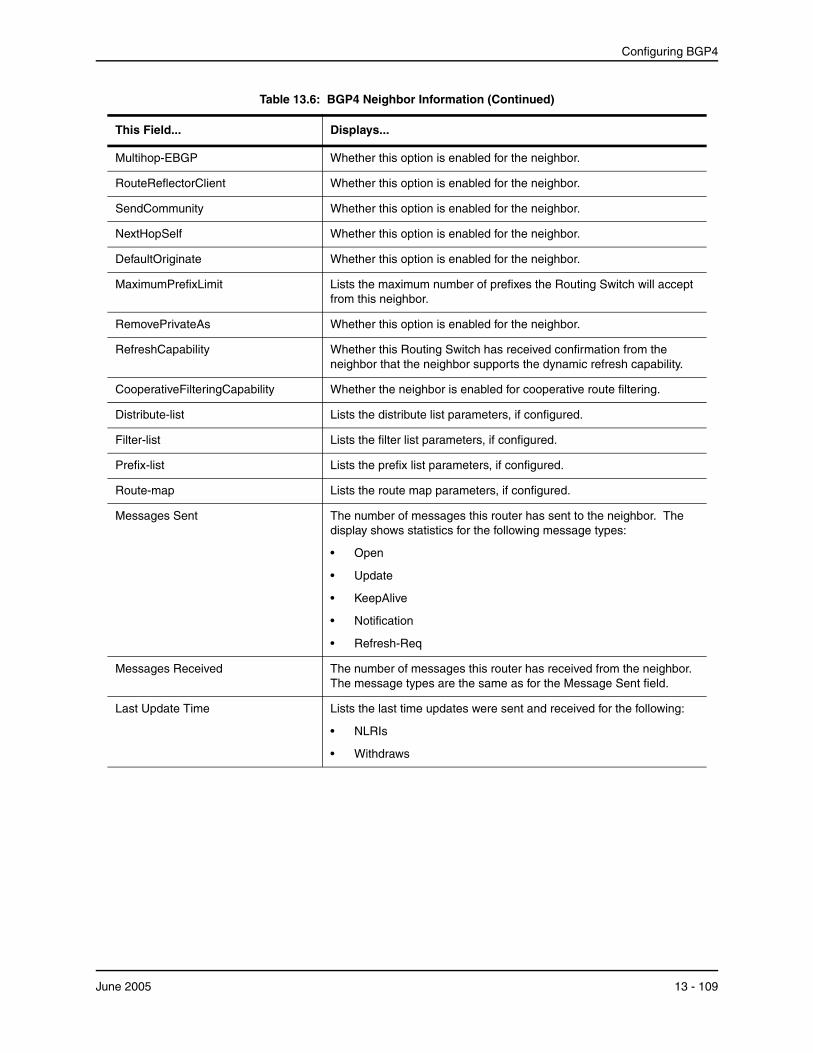
Configuring BGP4
Table 13.6: BGP4 Neighbor Information (Continued)
This Field...
Multihop-EBGP
RouteReflectorClient
SendCommunity
NextHopSelf
DefaultOriginate
MaximumPrefixLimit
RemovePrivateAs
RefreshCapability
CooperativeFilteringCapability
Distribute-list
Filter-list
Prefix-list
Route-map
Messages Sent
Messages Received
Last Update Time
Displays...
Whether this option is enabled for the neighbor.
Whether this option is enabled for the neighbor.
Whether this option is enabled for the neighbor.
Whether this option is enabled for the neighbor.
Whether this option is enabled for the neighbor.
Lists the maximum number of prefixes the Routing Switch will accept from this neighbor.
Whether this option is enabled for the neighbor.
Whether this Routing Switch has received confirmation from the neighbor that the neighbor supports the dynamic refresh capability.
Whether the neighbor is enabled for cooperative route filtering.
Lists the distribute list parameters, if configured.
Lists the filter list parameters, if configured.
Lists the prefix list parameters, if configured.
Lists the route map parameters, if configured.
The number of messages this router has sent to the neighbor. The display shows statistics for the following message types:
• Open
• Update
• KeepAlive
• Notification
• Refresh-Req
The number of messages this router has received from the neighbor. The message types are the same as for the Message Sent field.
Lists the last time updates were sent and received for the following:
• NLRIs
• Withdraws
June 2005 13 - 109

Advanced Configuration and Management Guide for ProCurve 9300/9400 Series Routing Switches
Table 13.6: BGP4 Neighbor Information (Continued)
This Field...
Last Connection Reset Reason
Displays...
The reason the previous session with this neighbor ended. The reason can be one of the following:
• Reasons described in the BGP specifications:
• Message Header Error
• Connection Not Synchronized
• Bad Message Length
• Bad Message Type
• OPEN Message Error
• Unsupported Version Number
• Bad Peer AS Number
• Bad BGP Identifier
• Unsupported Optional Parameter
• Authentication Failure
• Unacceptable Hold Time
• Unsupported Capability
• UPDATE Message Error
• Malformed Attribute List
• Unrecognized Well-known Attribute
• Missing Well-known Attribute
• Attribute Flags Error
• Attribute Length Error
• Invalid ORIGIN Attribute
• Invalid NEXT_HOP Attribute
• Optional Attribute Error
• Invalid Network Field
• Malformed AS_PATH
• Hold Timer Expired
• Finite State Machine Error
• Rcv Notification
13 - 110 June 2005
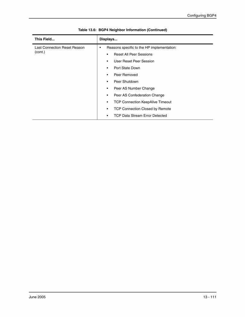
Configuring BGP4
Table 13.6: BGP4 Neighbor Information (Continued)
This Field...
Last Connection Reset Reason (cont.)
Displays...
• Reasons specific to the HP implementation:
• Reset All Peer Sessions
• User Reset Peer Session
• Port State Down
• Peer Removed
• Peer Shutdown
• Peer AS Number Change
• Peer AS Confederation Change
• TCP Connection KeepAlive Timeout
• TCP Connection Closed by Remote
• TCP Data Stream Error Detected
June 2005 13 - 111

Advanced Configuration and Management Guide for ProCurve 9300/9400 Series Routing Switches
Table 13.6: BGP4 Neighbor Information (Continued)
This Field...
Notification Sent
Notification Received
Displays...
If the router receives a NOTIFICATION message from the neighbor, the message contains an error code corresponding to one of the following errors. Some errors have subcodes that clarify the reason for the error. Where applicable, the subcode messages are listed underneath the error code messages.
• Message Header Error
• Connection Not Synchronized
• Bad Message Length
• Bad Message Type
• Unspecified
• Open Message Error
• Unsupported Version
• Bad Peer As
• Bad BGP Identifier
• Unsupported Optional Parameter
• Authentication Failure
• Unacceptable Hold Time
• Unspecified
• Update Message Error
• Malformed Attribute List
• Unrecognized Attribute
• Missing Attribute
• Attribute Flag Error
• Attribute Length Error
• Invalid Origin Attribute
• Invalid NextHop Attribute
• Optional Attribute Error
• Invalid Network Field
• Malformed AS Path
• Unspecified
• Hold Timer Expired
• Finite State Machine Error
• Cease
• Unspecified
See above.
13 - 112 June 2005

Configuring BGP4
Table 13.6: BGP4 Neighbor Information (Continued)
This Field...
TCP Connection state
Byte Sent
Byte Received
Local host
Local port
Remote host
Remote port
ISentSeq
SendNext
TotUnAck
TotSent
Displays...
The state of the connection with the neighbor. The connection can have one of the following states:
• LISTEN – Waiting for a connection request.
• SYN-SENT – Waiting for a matching connection request after having sent a connection request.
• SYN-RECEIVED – Waiting for a confirming connection request acknowledgment after having both received and sent a connection request.
• ESTABLISHED – Data can be sent and received over the connection. This is the normal operational state of the connection.
• FIN-WAIT-1 – Waiting for a connection termination request from the remote TCP, or an acknowledgment of the connection termination request previously sent.
• FIN-WAIT-2 – Waiting for a connection termination request from the remote TCP.
• CLOSE-WAIT – Waiting for a connection termination request from the local user.
• CLOSING – Waiting for a connection termination request acknowledgment from the remote TCP.
• LAST-ACK – Waiting for an acknowledgment of the connection termination request previously sent to the remote TCP (which includes an acknowledgment of its connection termination request).
• TIME-WAIT – Waiting for enough time to pass to be sure the remote TCP received the acknowledgment of its connection termination request.
• CLOSED – There is no connection state.
The number of bytes sent.
The number of bytes received.
The IP address of the Routing Switch.
The TCP port the Routing Switch is using for the BGP4 TCP session with the neighbor.
The IP address of the neighbor.
The TCP port the neighbor is using for the BGP4 TCP session with the Routing Switch.
The initial send sequence number for the session.
The next sequence number to be sent.
The number of sequence numbers sent by the Routing Switch that have not been acknowledged by the neighbor.
The number of sequence numbers sent to the neighbor.
June 2005 13 - 113

Advanced Configuration and Management Guide for ProCurve 9300/9400 Series Routing Switches
Table 13.6: BGP4 Neighbor Information (Continued)
This Field... Displays...
ReTrans The number of sequence numbers that the Routing Switch retransmitted because they were not acknowledged.
UnAckSeq The current acknowledged sequence number.
IRcvSeq The initial receive sequence number for the session.
RcvNext The next sequence number expected from the neighbor.
SendWnd The size of the send window.
TotalRcv The number of sequence numbers received from the neighbor.
DupliRcv The number of duplicate sequence numbers received from the neighbor.
RcvWnd The size of the receive window.
SendQue The number of sequence numbers in the send queue.
RcvQue The number of sequence numbers in the receive queue.
CngstWnd The number of times the window has changed.
Displaying Route Information for a Neighbor
You can display routes based on the following criteria:
• A summary of the routes for a specific neighbor.
• The routes received from the neighbor that the Routing Switch selected as the best routes to their destinations.
• The routes received from the neighbor that are the best BGP4 routes to their destinations, but were nonetheless not installed in the IP route table because the Routing Switch received better routes from other sources (such as OSPF, RIP, or static IP routes).
• The routes that are unreachable because the Routing Switch does not have a valid RIP, OSPF, or static route to the next hop.
• Routes for a specific network advertised by the Routing Switch to the neighbor.
• The Routing Information Base (RIB) for a specific network advertised to the neighbor. You can display the RIB regardless of whether the Routing Switch has already sent it to the neighbor.
To display route information for a neighbor, use the following CLI methods.
13 - 114 June 2005

Configuring BGP4
1
USING THE CLI
Displaying Summary Route Information To display summary route information, enter a command such as the following at any level of the CLI:
ProCurveRS(config-bgp-router)# show ip bgp neighbor 10.1.0.2 routes-summary IP Address: 10.1.0.2
Routes Accepted/Installed:1, Filtered/Kept:11, Filtered:11 Routes Selected as BEST Routes:1
BEST Routes not Installed in IP Forwarding Table:0 Unreachable Routes (no IGP Route for NEXTHOP):0 History Routes:0
NLRIs Received in Update Message:24, Withdraws:0 (0), Replacements:1 NLRIs Discarded due to
Maximum Prefix Limit:0, AS Loop:0Invalid Nexthop:0, Invalid Nexthop Address:0.0.0.0 Duplicated Originator_ID:0, Cluster_ID:0
Routes Advertised:0, To be Sent:0, To be Withdrawn:0 NLRIs Sent in Update Message:0, Withdraws:0, Replacements:0
Peer Out of Memory Count for: Receiving Update Messages:0, Accepting Routes(NLRI):0 Attributes:0, Outbound Routes(RIB-out):0
This display shows the following information.
Table 13.7: BGP4 Route Summary Information for a Neighbor
This Field...
Routes Received
Routes Selected as BEST Routes
BEST Routes not Installed in IP Forwarding Table
Unreachable Routes
History Routes
Displays...
How many routes the Routing Switch has received from the neighbor during the current BGP4 session.
• Accepted/Installed – Indicates how many of the received routes the Routing Switch accepted and installed in the BGP4 route table.
• Filtered – Indicates how many of the received routes the Routing Switch did not accept or install because they were denied by filters on the Routing Switch.
The number of routes that the Routing Switch selected as the best routes to their destinations.
The number of routes received from the neighbor that are the best BGP4 routes to their destinations, but were nonetheless not installed in the IP route table because the Routing Switch received better routes from other sources (such as OSPF, RIP, or static IP routes).
The number of routes received from the neighbor that are unreachable because the Routing Switch does not have a valid RIP, OSPF, or static route to the next hop.
The number of routes that are down but are being retained for route flap dampening purposes.
June 2005 13 - 115
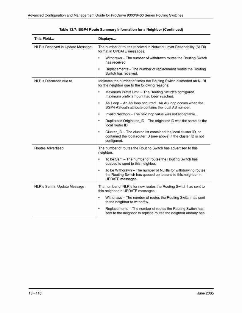
Advanced Configuration and Management Guide for ProCurve 9300/9400 Series Routing Switches
Table 13.7: BGP4 Route Summary Information for a Neighbor (Continued)
This Field...
NLRIs Received in Update Message
NLRIs Discarded due to
Routes Advertised
NLRIs Sent in Update Message
Displays...
The number of routes received in Network Layer Reachability (NLRI) format in UPDATE messages.
• Withdraws – The number of withdrawn routes the Routing Switch has received.
• Replacements – The number of replacement routes the Routing Switch has received.
Indicates the number of times the Routing Switch discarded an NLRI for the neighbor due to the following reasons:
• Maximum Prefix Limit – The Routing Switch’s configured maximum prefix amount had been reached.
• AS Loop – An AS loop occurred. An AS loop occurs when the BGP4 AS-path attribute contains the local AS number.
• Invalid Nexthop – The next hop value was not acceptable.
• Duplicated Originator_ID – The originator ID was the same as the local router ID.
• Cluster_ID – The cluster list contained the local cluster ID, or contained the local router ID (see above) if the cluster ID is not configured.
The number of routes the Routing Switch has advertised to this neighbor.
• To be Sent – The number of routes the Routing Switch has queued to send to this neighbor.
• To be Withdrawn – The number of NLRIs for withdrawing routes the Routing Switch has queued up to send to this neighbor in UPDATE messages.
The number of NLRIs for new routes the Routing Switch has sent to this neighbor in UPDATE messages.
• Withdraws – The number of routes the Routing Switch has sent to the neighbor to withdraw.
• Replacements – The number of routes the Routing Switch has sent to the neighbor to replace routes the neighbor already has.
13 - 116 June 2005
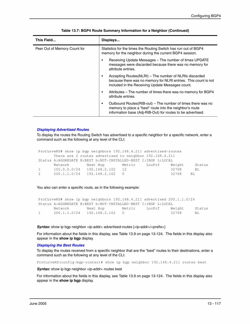
Configuring BGP4
Table 13.7: BGP4 Route Summary Information for a Neighbor (Continued)
This Field... Displays...
Peer Out of Memory Count for Statistics for the times the Routing Switch has run out of BGP4 memory for the neighbor during the current BGP4 session.
• Receiving Update Messages – The number of times UPDATE messages were discarded because there was no memory for attribute entries.
• Accepting Routes(NLRI) – The number of NLRIs discarded because there was no memory for NLRI entries. This count is not included in the Receiving Update Messages count.
• Attributes – The number of times there was no memory for BGP4 attribute entries.
• Outbound Routes(RIB-out) – The number of times there was no memory to place a “best” route into the neighbor's route information base (Adj-RIB-Out) for routes to be advertised.
Displaying Advertised Routes To display the routes the Routing Switch has advertised to a specific neighbor for a specific network, enter a command such as the following at any level of the CLI:
ProCurveRS# show ip bgp neighbors 192.168.4.211 advertised-routes There are 2 routes advertised to neighbor 192.168.4.211
Status A:AGGREGATE B:BEST b:NOT-INSTALLED-BEST I:IBGP L:LOCAL Network Next Hop Metric LocPrf Weight Status
1 102.0.0.0/24 192.168.2.102 12 32768 BL2 200.1.1.0/24 192.168.2.102 0 32768 BL
You also can enter a specific route, as in the following example:
ProCurveRS# show ip bgp neighbors 192.168.4.211 advertised 200.1.1.0/24Status A:AGGREGATE B:BEST b:NOT-INSTALLED-BEST I:IBGP L:LOCAL
Network Next Hop Metric LocPrf Weight Status1 200.1.1.0/24 192.168.2.102 0 32768 BL
Syntax: show ip bgp neighbor <ip-addr> advertised-routes [<ip-addr>/<prefix>]
For information about the fields in this display, see Table 13.9 on page 13-124. The fields in this display also appear in the show ip bgp display.
Displaying the Best Routes To display the routes received from a specific neighbor that are the “best” routes to their destinations, enter a command such as the following at any level of the CLI:
ProCurveRS(config-bgp-router)# show ip bgp neighbor 192.168.4.211 routes best
Syntax: show ip bgp neighbor <ip-addr> routes best
For information about the fields in this display, see Table 13.9 on page 13-124. The fields in this display also appear in the show ip bgp display.
June 2005 13 - 117

Advanced Configuration and Management Guide for ProCurve 9300/9400 Series Routing Switches
1
Displaying the Best Routes that Were Nonetheless Not Installed in the IP Route Table To display the BGP4 routes received from a specific neighbor that are the “best” routes to their destinations but are not installed in the Routing Switch’s IP route table, enter a command such as the following at any level of the CLI:
ProCurveRS(config-bgp-router)# show ip bgp neighbor 192.168.4.211 routes not-installed-best
Each of the displayed routes is a valid path to its destination, but the Routing Switch received another path from a different source (such as OSPF, RIP, or a static route) that has a lower administrative distance. The Routing Switch always selects the path with the lowest administrative distance to install in the IP route table.
Syntax: show ip bgp neighbor <ip-addr> routes not-installed-best
For information about the fields in this display, see Table 13.9 on page 13-124. The fields in this display also appear in the show ip bgp display.
Displaying the Routes Whose Destinations Are Unreachable To display BGP4 routes whose destinations are unreachable using any of the BGP4 paths in the BGP4 route table, enter a command such as the following at any level of the CLI:
ProCurveRS(config-bgp-router)# show ip bgp neighbor 192.168.4.211 routes unreachable
Syntax: show ip bgp neighbor <ip-addr> routes unreachable
For information about the fields in this display, see Table 13.9 on page 13-124. The fields in this display also appear in the show ip bgp display.
Displaying the Adj-RIB-Out for a Neighbor To display the Routing Switch’s current BGP4 Routing Information Base (Adj-RIB-Out) for a specific neighbor and a specific destination network, enter a command such as the following at any level of the CLI:
ProCurveRS(config-bgp-router)# show ip bgp neighbor 192.168.4.211 rib-out-routes 192.168.1.0/24Status A:AGGREGATE B:BEST b:NOT-INSTALLED-BEST I:IBGP L:LOCAL
Prefix Next Hop Metric LocPrf Weight Status 200.1.1.0/24 0.0.0.0 0 101 32768 BL
The Adj-RIB-Out contains the routes that the Routing Switch either has most recently sent to the neighbor or is about to send to the neighbor.
Syntax: show ip bgp neighbor <ip-addr> rib-out-routes [<ip-addr>/<prefix>]
For information about the fields in this display, see Table 13.9 on page 13-124. The fields in this display also appear in the show ip bgp display.
USING THE WEB MANAGEMENT INTERFACE
1. Log on to the device using a valid user name and password for read-only or read-write access. The System configuration panel is displayed.
2. Click on the plus sign next to Monitor in the tree view to expand the list of monitoring options.
3. Click on the plus sign next to BGP in the tree view to expand the list of BGP option links.
4. Click on the Neighbor link to display the BGP Neighbor Statistics panel.
Displaying Peer Group Information You can display configuration information for peer groups.
13 - 118 June 2005

Configuring BGP4
1
USING THE CLI
To display peer-group information, enter a command such as the following at the Privileged EXEC level of the CLI:
ProCurveRS# show ip bgp peer-group pg1BGP peer-group is pg
Description: peer group abc SendCommunity: yes NextHopSelf: yes DefaultOriginate: yes
Members: IP Address: 192.168.10.10, AS: 65111
Syntax: show ip bgp peer-group [<peer-group-name>]
Only the parameters that have values different from their defaults are listed.
Displaying Summary Route Information To display summary route information, use the following CLI method.
USING THE CLI
To display summary statistics for all the routes in the Routing Switch’s BGP4 route table, enter a command such as the following at any level of the CLI:
ProCurveRS(config-bgp-router)# show ip bgp routes summary Total number of BGP routes (NLRIs) Installed : 20 Distinct BGP destination networks : 20
Filtered BGP routes for soft reconfig : 100178 Routes originated by this router : 2 Routes selected as BEST routes : 19 BEST routes not installed in IP forwarding table : 1 Unreachable routes (no IGP route for NEXTHOP) : 1 IBGP routes selected as best routes : 0 EBGP routes selected as best routes : 17
Syntax: show ip bgp routes summary
This display shows the following information.
Table 13.8: BGP4 Summary Route Information
This Field...
Total number of BGP routes (NLRIs) Installed
Distinct BGP destination networks
Filtered BGP routes for soft reconfig
Routes originated by this router
Displays...
The number of BGP4 routes the Routing Switch has installed in the BGP4 route table.
The number of destination networks the installed routes represent. The BGP4 route table can have multiple routes to the same network.
The number of route updates received from soft-reconfigured neighbors or peer groups that have been filtered out but retained. For information about soft reconfiguration, see “Using Soft Reconfiguration” on page 13-133.
The number of routes in the BGP4 route table that this Routing Switch originated.
June 2005 13 - 119

Advanced Configuration and Management Guide for ProCurve 9300/9400 Series Routing Switches
Table 13.8: BGP4 Summary Route Information (Continued)
This Field...
Routes selected as BEST routes
BEST routes not installed in IP forwarding table
Unreachable routes (no IGP route for The number of routes in the BGP4 route table whose destinations are NEXTHOP) unreachable because the next hop is unreachable.
IBGP routes selected as best routes The number of “best” routes in the BGP4 route table that are IBGP routes.
EBGP routes selected as best routes
Displays...
The number of routes in the BGP4 route table that this Routing Switch has selected as the best routes to the destinations.
The number of BGP4 routes that are the best BGP4 routes to their destinations but were not installed in the IP route table because the Routing Switch received better routes from other sources (such as OSPF, RIP, or static IP routes).
The number of “best” routes in the BGP4 route table that are EBGP routes.
USING THE WEB MANAGEMENT INTERFACE
You cannot display summary route information using the Web management interface.
Displaying the BGP4 Route Table BGP4 uses filters you define as well as the algorithm described in “How BGP4 Selects a Path for a Route” on page 13-3 to determine the preferred route to a destination. BGP4 sends only the preferred route to the router’s IP table. However, if you want to view all the routes BGP4 knows about, you can display the BGP4 table using either of the following methods.
USING THE CLI
To view the BGP4 route table, enter the following command:
ProCurveRS(config-bgp-router)# show ip bgp routesTotal number of BGP Routes: 97371Status A:AGGREGATE B:BEST b:NOT-INSTALLED-BEST C:CONFED_EBGP D:DAMPED
E:EBGP H:HISTORY I:IBGP L:LOCAL M:MULTIPATH S:SUPPRESSED
1 Prefix Next Hop
3.0.0.0/8 192.168.4.106 AS_PATH: 65001 4355 701 80
Metric LocPrf 100
Weight Status 0 BE
2 4.0.0.0/8 192.168.4.106 AS_PATH: 65001 4355 1
100 0 BE
3 4.60.212.0/22 192.168.4.106 AS_PATH: 65001 4355 701 1 189
100 0 BE
4 6.0.0.0/8 192.168.4.106 AS_PATH: 65001 4355 3356 7170 1455
100 0 BE
5 8.8.1.0/24 AS_PATH: 65001
192.168.4.106 0 100 0 BE
Syntax: show ip bgp routes [[network] <ip-addr>] | <num> | [age <secs>] | [as-path-access-list <num>] | [best] | [cidr-only] | [community <num> | no-export | no-advertise | internet | local-as] | [community-access-list <num>] | [community-list <num> | [detail <option>] | [filter-list <num, num,...>] | [next-hop <ip-addr>] | [no-best] | [not-installed-best] | [prefix-list <string>] | [regular-expression <regular-expression>] | [route-map <map-name>] | [summary] | [unreachable]
The <ip-addr> option displays routes for a specific network. The network keyword is optional. You can enter thenetwork address without entering “network” in front of it.
13 - 120 June 2005

Configuring BGP4
The <num> option specifies the table entry with which you want the display to start. For example, if you want tolist entries beginning with table entry 100, specify 100.
The age <secs> parameter displays only the routes that have been received or updated more recently than the number of seconds you specify.
The as-path-access-list <num> parameter filters the display using the specified AS-path ACL.
The best parameter displays the routes received from the neighbor that the Routing Switch selected as the best routes to their destinations.
The cidr-only option lists only the routes whose network masks do not match their class network length.
The community option lets you display routes for a specific community. You can specify local-as, no-export, no-advertise, internet, or a private community number. You can specify the community number as either two five-digit integer values of up to 1– 65535, separated by a colon (for example, 12345:6789) or a single long integer value.
The community-access-list <num> parameter filters the display using the specified community ACL.
The community-list option lets you display routes that match a specific community filter.
The detail option lets you display more details about the routes. You can refine your request by also specifyingone of the other display options after the detail keyword.
The filter-list option displays routes that match a specific address filter list.
The next-hop <ip-addr> option displays the routes for a given next-hop IP address.
The no-best option displays the routes for which none of the routes to a given prefix were selected as the best route. The IP route table does not contain a BGP4 route for any of the routes listed by the command.
The not-installed-best option displays the routes received from the neighbor that are the best BGP4 routes to their destinations, but were nonetheless not installed in the IP route table because the Routing Switch received better routes from other sources (such as OSPF, RIP, or static IP routes).
The prefix-list <string> parameter filters the display using the specified IP prefix list.
The regular-expression <regular-expression> option filters the display based on a regular expression. See “Using Regular Expressions” on page 13-57.
The route-map <map-name> parameter filters the display using the specified route map. The software displays only the routes that match the match statements in the route map. The software disregards the route map’s set statements.
The summary option displays summary information for the routes.
The unreachable option displays the routes that are unreachable because the Routing Switch does not have avalid RIP, OSPF, or static route to the next hop.
June 2005 13 - 121

Advanced Configuration and Management Guide for ProCurve 9300/9400 Series Routing Switches
Displaying the Best BGP4 Routes
To display all the BGP4 routes in the Routing Switch’s BGP4 route table that are the best routes to their destinations, enter a command such as the following at any level of the CLI:
ProCurveRS(config-bgp-router)# show ip bgp routes bestSearching for matching routes, use ^C to quit...Status A:AGGREGATE B:BEST b:NOT-INSTALLED-BEST C:CONFED_EBGP D:DAMPED
E:EBGP H:HISTORY I:IBGP L:LOCAL M:MULTIPATH S:SUPPRESSED F:FILTERED Prefix Next Hop Metric LocPrf Weight Status
1 3.0.0.0/8 192.168.4.106 100 0 BE AS_PATH: 65001 4355 701 80
2 4.0.0.0/8 192.168.4.106 100 0 BE AS_PATH: 65001 4355 1
3 4.60.212.0/22 192.168.4.106 100 0 BE AS_PATH: 65001 4355 701 1 189
4 6.0.0.0/8 192.168.4.106 100 0 BE AS_PATH: 65001 4355 3356 7170 1455
5 9.2.0.0/16 192.168.4.106 100 0 BE AS_PATH: 65001 4355 701
Syntax: show ip bgp routes best
For information about the fields in this display, see Table 13.9 on page 13-124. The fields in this display also appear in the show ip bgp display.
Displaying Those Best BGP4 Routes that Are Nonetheless Not in the IP Route Table
When the Routing Switch has multiple routes to a destination from different sources (such as BGP4, OSPF, RIP, or static routes), the Routing Switch selects the route with the lowest administrative distance as the best route, and installs that route in the IP route table.
To display the BGP4 routes are the “best” routes to their destinations but are not installed in the Routing Switch’s IP route table, enter a command such as the following at any level of the CLI:
ProCurveRS(config-bgp-router)# show ip bgp routes not-installed-bestSearching for matching routes, use ^C to quit...Status A:AGGREGATE B:BEST b:NOT-INSTALLED-BEST C:CONFED_EBGP D:DAMPED
E:EBGP H:HISTORY I:IBGP L:LOCAL M:MULTIPATH S:SUPPRESSED F:FILTERED Prefix Next Hop Metric LocPrf Weight Status
1 192.168.4.0/24 192.168.4.106 0 100 0 bE AS_PATH: 65001
Each of the displayed routes is a valid path to its destination, but the Routing Switch received another path from a different source (such as OSPF, RIP, or a static route) that has a lower administrative distance. The Routing Switch always selects the path with the lowest administrative distance to install in the IP route table.
Notice that the route status in this example is the new status, “b”. See Table 13.9 on page 13-124 for a description.
Syntax: show ip bgp routes not-installed-best
For information about the fields in this display, see Table 13.9 on page 13-124. The fields in this display also appear in the show ip bgp display.
NOTE: To display the routes that the Routing Switch has selected as the best routes and installed in the IP route table, display the IP route table using the show ip route command.
13 - 122 June 2005
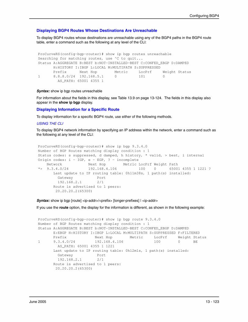
Configuring BGP4
Displaying BGP4 Routes Whose Destinations Are Unreachable
To display BGP4 routes whose destinations are unreachable using any of the BGP4 paths in the BGP4 route table, enter a command such as the following at any level of the CLI:
ProCurveRS(config-bgp-router)# show ip bgp routes unreachableSearching for matching routes, use ^C to quit...Status A:AGGREGATE B:BEST b:NOT-INSTALLED-BEST C:CONFED_EBGP D:DAMPED
H:HISTORY I:IBGP L:LOCAL M:MULTIPATH S:SUPPRESSED Prefix Next Hop Metric LocPrf Weight Status
1 8.8.8.0/24 192.168.5.1 0 101 0 AS_PATH: 65001 4355 1
Syntax: show ip bgp routes unreachable
For information about the fields in this display, see Table 13.9 on page 13-124. The fields in this display also appear in the show ip bgp display.
Displaying Information for a Specific Route
To display information for a specific BGP4 route, use either of the following methods.
USING THE CLI
To display BGP4 network information by specifying an IP address within the network, enter a command such as the following at any level of the CLI:
ProCurveRS(config-bgp-router)# show ip bgp 9.3.4.0Number of BGP Routes matching display condition : 1Status codes: s suppressed, d damped, h history, * valid, > best, i internalOrigin codes: i - IGP, e - EGP, ? - incomplete Network Next Hop Metric LocPrf Weight Path*> 9.3.4.0/24 192.168.4.106 100 0 65001 4355 1 1221 ?
Last update to IP routing table: 0h11m38s, 1 path(s) installed: Gateway Port 192.168.2.1 2/1 Route is advertised to 1 peers: 20.20.20.2(65300)
Syntax: show ip bgp [route] <ip-addr>/<prefix> [longer-prefixes] | <ip-addr>
If you use the route option, the display for the information is different, as shown in the following example:
ProCurveRS(config-bgp-router)# show ip bgp route 9.3.4.0Number of BGP Routes matching display condition : 1Status A:AGGREGATE B:BEST b:NOT-INSTALLED-BEST C:CONFED_EBGP D:DAMPED
E:EBGP H:HISTORY I:IBGP L:LOCAL M:MULTIPATH S:SUPPRESSED F:FILTERED Prefix Next Hop Metric LocPrf Weight Status
1 9.3.4.0/24 192.168.4.106 100 0 BE AS_PATH: 65001 4355 1 1221 Last update to IP routing table: 0h12m1s, 1 path(s) installed: Gateway Port 192.168.2.1 2/1 Route is advertised to 1 peers: 20.20.20.2(65300)
June 2005 13 - 123

Advanced Configuration and Management Guide for ProCurve 9300/9400 Series Routing Switches
These displays show the following information.
Table 13.9: BGP4 Network Information
This Field...
Number of BGP Routes matching display condition
The number of routes that matched the display parameters you entered. This is the number of routes displayed by the command.
Status codes A list of the characters the display uses to indicate the route’s status. The status code appears in the left column of the display, to the left of each route. The status codes are described in the command’s output.
Note: This field appears only if you do not enter the route option.
Prefix
Next Hop
Metric
LocPrf
Weight
Path
Origin code
Displays...
The network address and prefix.
The next-hop router for reaching the network from the Routing Switch.
The value of the route’s MED attribute. If the route does not have a metric, this field is blank.
The degree of preference for this route relative to other routes in the local AS. When the BGP4 algorithm compares routes on the basis of local preferences, the route with the higher local preference is chosen. The preference can have a value from 0 – 4294967295.
The value that this router associates with routes from a specific neighbor. For example, if the router receives routes to the same destination from two BGP4 neighbors, the router prefers the route from the neighbor with the larger weight.
The route’s AS path.
Note: This field appears only if you do not enter the route option.
A character the display uses to indicate the route’s origin. The origin code appears to the right of the AS path (Path field). The origin codes are described in the command’s output.
Note: This field appears only if you do not enter the route option.
13 - 124 June 2005

Configuring BGP4
Table 13.9: BGP4 Network Information (Continued)
This Field... Displays...
Status The route’s status, which can be one or more of the following:
• A – AGGREGATE. The route is an aggregate route for multiple networks.
• B – BEST. BGP4 has determined that this is the optimal route to the destination.
Note: If the “b” is shown in lowercase, the software was not able to install the route in the IP route table.
• b – NOT-INSTALLED-BEST. The routes received from the neighbor are the best BGP4 routes to their destinations, but were nonetheless not installed in the IP route table because the Routing Switch received better routes from other sources (such as OSPF, RIP, or static IP routes).
• C – CONFED_EBGP. The route was learned from a neighbor in the same confederation and AS, but in a different sub-AS within the confederation.
• D – DAMPED. This route has been dampened (by the route dampening feature), and is currently unusable.
• H – HISTORY. Route dampening is configured for this route, and the route has a history of flapping and is unreachable now.
• I – INTERNAL. The route was learned through BGP4.
• L – LOCAL. The route originated on this Routing Switch.
• M – MULTIPATH. BGP4 load sharing is enabled and this route was selected as one of the best ones to the destination. The best route among the multiple paths also is marked with “B”.
Note: If the “m” is shown in lowercase, the software was not able to install the route in the IP route table.
• S – SUPPRESSED. This route was suppressed during aggregation and thus is not advertised to neighbors.
Note: This field appears only if you enter the route option.
Displaying Route Details
Here is an example of the information displayed when you use the detail option. In this example, the information for one route is shown.
ProCurveRS# show ip bgp routes detailTotal number of BGP Routes: 2 Status A:AGGREGATE B:BEST b:NOT-INSTALLED-BEST C:CONFED_EBGP D:DAMPED
E:EBGP H:HISTORY I:IBGP L:LOCAL M:MULTIPATH S:SUPPRESSED Prefix: 10.5.0.0/24, Status: BME, Age: 0h28m28s NEXT_HOP: 201.1.1.2, Learned from Peer: 10.1.0.2 (5) LOCAL_PREF: 101, MED: 0, ORIGIN: igp, Weight: 10 AS_PATH: 5 Adj_RIB_out count: 4, Admin distance 20
1
June 2005 13 - 125
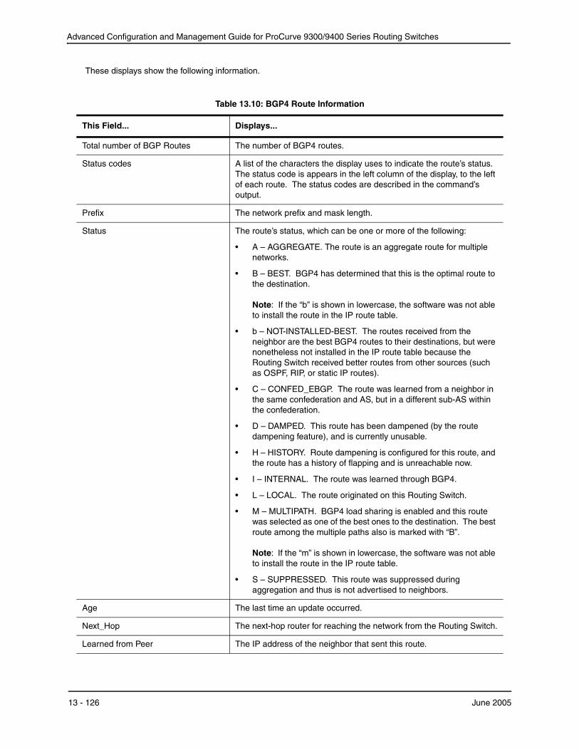
Advanced Configuration and Management Guide for ProCurve 9300/9400 Series Routing Switches
These displays show the following information.
Table 13.10: BGP4 Route Information
This Field...
Total number of BGP Routes
Status codes
Prefix
Status
Age
Next_Hop
Learned from Peer
Displays...
The number of BGP4 routes.
A list of the characters the display uses to indicate the route’s status. The status code is appears in the left column of the display, to the left of each route. The status codes are described in the command’s output.
The network prefix and mask length.
The route’s status, which can be one or more of the following:
• A – AGGREGATE. The route is an aggregate route for multiple networks.
• B – BEST. BGP4 has determined that this is the optimal route to the destination.
Note: If the “b” is shown in lowercase, the software was not able to install the route in the IP route table.
• b – NOT-INSTALLED-BEST. The routes received from the neighbor are the best BGP4 routes to their destinations, but were nonetheless not installed in the IP route table because the Routing Switch received better routes from other sources (such as OSPF, RIP, or static IP routes).
• C – CONFED_EBGP. The route was learned from a neighbor in the same confederation and AS, but in a different sub-AS within the confederation.
• D – DAMPED. This route has been dampened (by the route dampening feature), and is currently unusable.
• H – HISTORY. Route dampening is configured for this route, and the route has a history of flapping and is unreachable now.
• I – INTERNAL. The route was learned through BGP4.
• L – LOCAL. The route originated on this Routing Switch.
• M – MULTIPATH. BGP4 load sharing is enabled and this route was selected as one of the best ones to the destination. The best route among the multiple paths also is marked with “B”.
Note: If the “m” is shown in lowercase, the software was not able to install the route in the IP route table.
• S – SUPPRESSED. This route was suppressed during aggregation and thus is not advertised to neighbors.
The last time an update occurred.
The next-hop router for reaching the network from the Routing Switch.
The IP address of the neighbor that sent this route.
13 - 126 June 2005
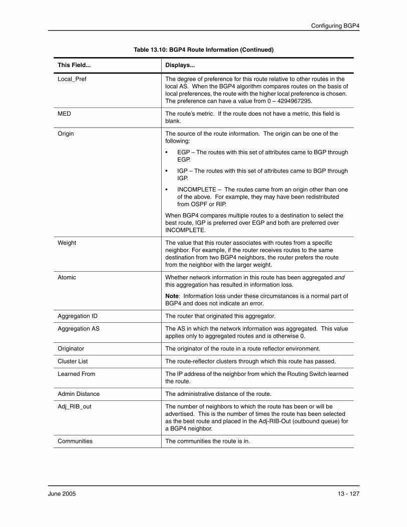
Configuring BGP4
Table 13.10: BGP4 Route Information (Continued)
This Field... Displays...
Local_Pref The degree of preference for this route relative to other routes in the local AS. When the BGP4 algorithm compares routes on the basis of local preferences, the route with the higher local preference is chosen. The preference can have a value from 0 – 4294967295.
MED The route’s metric. If the route does not have a metric, this field is blank.
Origin The source of the route information. The origin can be one of the following:
• EGP – The routes with this set of attributes came to BGP through EGP.
• IGP – The routes with this set of attributes came to BGP through IGP.
• INCOMPLETE – The routes came from an origin other than one of the above. For example, they may have been redistributed from OSPF or RIP.
When BGP4 compares multiple routes to a destination to select the best route, IGP is preferred over EGP and both are preferred over INCOMPLETE.
Weight The value that this router associates with routes from a specific neighbor. For example, if the router receives routes to the same destination from two BGP4 neighbors, the router prefers the route from the neighbor with the larger weight.
Atomic Whether network information in this route has been aggregated and this aggregation has resulted in information loss.
Note: Information loss under these circumstances is a normal part of BGP4 and does not indicate an error.
Aggregation ID The router that originated this aggregator.
Aggregation AS The AS in which the network information was aggregated. This value applies only to aggregated routes and is otherwise 0.
Originator The originator of the route in a route reflector environment.
Cluster List The route-reflector clusters through which this route has passed.
Learned From The IP address of the neighbor from which the Routing Switch learned the route.
Admin Distance The administrative distance of the route.
Adj_RIB_out The number of neighbors to which the route has been or will be advertised. This is the number of times the route has been selected as the best route and placed in the Adj-RIB-Out (outbound queue) for a BGP4 neighbor.
Communities The communities the route is in.
June 2005 13 - 127

Advanced Configuration and Management Guide for ProCurve 9300/9400 Series Routing Switches
USING THE WEB MANAGEMENT INTERFACE
1. Log on to the device using a valid user name and password for read-only or read-write access. The System configuration panel is displayed.
2. Click on the plus sign next to Monitor in the tree view to expand the list of monitoring options.
3. Click on the plus sign next to BGP in the tree view to expand the list of BGP option links.
4. Click on the Routes link to display the BGP Routes panel.
Displaying BGP4 Route-Attribute Entries The route-attribute entries table lists the sets of BGP4 attributes stored in the router’s memory. Each set of attributes is unique and can be associated with one or more routes. In fact, the router typically has fewer route attribute entries than routes. To display the route-attribute entries table, use one of the following methods.
USING THE CLI
To display the IP route table, enter the following command:
ProCurveRS# show ip bgp attribute-entries
Syntax: show ip bgp attribute-entries
Here is an example of the information displayed by this command. A zero value indicates that the attribute is not set.
ProCurveRS# show ip bgp attribute-entries Total number of BGP Attribute Entries: 7753
1 Next Hop :192.168.11.1 Metric :0 Origin:IGP Originator:0.0.0.0 Cluster List:None Aggregator:AS Number :0 Router-ID:0.0.0.0 Atomic:FALSE Local Pref:100 Communities:Internet AS Path :(65002) 65001 4355 2548 3561 5400 6669 5548
2 Next Hop :192.168.11.1 Metric :0 Origin:IGP Originator:0.0.0.0 Cluster List:None Aggregator:AS Number :0 Router-ID:0.0.0.0 Atomic:FALSE Local Pref:100 Communities:Internet AS Path :(65002) 65001 4355 2548
This display shows the following information.
Table 13.11: BGP4 Route-Attribute Entries Information
This Field...
Total number of BGP Attribute Entries
Next Hop
Metric
Displays...
The number of routes contained in this router’s BGP4 route table.
The IP address of the next hop router for routes that have this set of attributes.
The cost of the routes that have this set of attributes.
13 - 128 June 2005

Configuring BGP4
Table 13.11: BGP4 Route-Attribute Entries Information (Continued)
This Field...
Origin
Originator The originator of the route in a route reflector environment.
Cluster List The route-reflector clusters through which this set of attributes has passed.
Aggregator
Atomic
Local Pref
Communities
AS Path
Displays...
The source of the route information. The origin can be one of the following:
• EGP – The routes with this set of attributes came to BGP through EGP.
• IGP – The routes with this set of attributes came to BGP through IGP.
• INCOMPLETE – The routes came from an origin other than one of the above. For example, they may have been redistributed from OSPF or RIP.
When BGP4 compares multiple routes to a destination to select the best route, IGP is preferred over EGP and both are preferred over INCOMPLETE.
Aggregator information:
• AS Number shows the AS in which the network information in the attribute set was aggregated. This value applies only to aggregated routes and is otherwise 0.
• Router-ID shows the router that originated this aggregator.
Whether the network information in this set of attributes has been aggregated and this aggregation has resulted in information loss.
• TRUE – Indicates information loss has occurred
• FALSE – Indicates no information loss has occurred
Note: Information loss under these circumstances is a normal part of BGP4 and does not indicate an error.
The degree of preference for routes that use this set of attributes relative to other routes in the local AS.
The communities that routes with this set of attributes are in.
The ASs through which routes with this set of attributes have passed. The local AS is shown in parentheses.
USING THE WEB MANAGEMENT INTERFACE
1. Log on to the device using a valid user name and password for read-only or read-write access. The System configuration panel is displayed.
2. Click on the plus sign next to Monitor in the tree view to expand the list of monitoring options.
3. Click on the plus sign next to BGP in the tree view to expand the list of BGP option links.
4. Click on the Attributes link to display the BGP Attributes Entries panel.
Displaying the Routes BGP4 Has Placed in the IP Route Table The IP route table indicates the routes it has received from BGP4 by listing “BGP” as the route type. You can view the IP route table using either of the following methods.
June 2005 13 - 129

Advanced Configuration and Management Guide for ProCurve 9300/9400 Series Routing Switches
USING THE CLI
To display the IP route table, enter the following command:
ProCurveRS# show ip route
Syntax: show ip route [<ip-addr> | <num> | bgp | ospf | rip]
Here is an example of the information displayed by this command. Notice that most of the routes in this example have type “B”, indicating that their source is BGP4.
ProCurveRS# show ip route
Total number of IP routes: 50834
B:BGP D:Directly-Connected O:OSPF R:RIP S:Static
Network Address NetMask Gateway Port Cost Type3.0.0.0 255.0.0.0 192.168.13.2 1/1 0 B 4.0.0.0 255.0.0.0 192.168.13.2 1/1 0 B 9.20.0.0 255.255.128.0 192.168.13.2 1/1 0 B 10.1.0.0 255.255.0.0 0.0.0.0 1/1 1 D 10.10.11.0 255.255.255.0 0.0.0.0 2/24 1 D 12.2.97.0 255.255.255.0 192.168.13.2 1/1 0 B 12.3.63.0 255.255.255.0 192.168.13.2 1/1 0 B 12.3.123.0 255.255.255.0 192.168.13.2 1/1 0 B 12.5.252.0 255.255.254.0 192.168.13.2 1/1 0 B 12.6.42.0 255.255.254.0 192.168.13.2 1/1 0 B
remaining 50824 entries not shown...
USING THE WEB MANAGEMENT INTERFACE
1. Log on to the device using a valid user name and password for read-only or read-write access. The System configuration panel is displayed.
2. Click on the plus sign next to Monitor in the tree view to expand the list of monitoring options.
3. Click on the plus sign next to IP in the tree view to expand the list of IP option links.
4. Click on the Routing Table link to display the IP route table.
Displaying Route Flap Dampening Statistics To display route flap dampening statistics, use the following CLI method.
USING THE CLI
To display route dampening statistics or all the dampened routes, enter the following command at any level of the CLI:
ProCurveRS# show ip bgp flap-statistics
Total number of flapping routes: 414 Status Code >:best d:damped h:history *:valid Network From Flaps Since Reuse Path
h> 192.50.206.0/23 166.90.213.77 1 0 :0 :13 0 :0 :0 65001 4355 1 701h> 203.255.192.0/20 166.90.213.77 1 0 :0 :13 0 :0 :0 65001 4355 1 7018 h> 203.252.165.0/24 166.90.213.77 1 0 :0 :13 0 :0 :0 65001 4355 1 7018 h> 192.50.208.0/23 166.90.213.77 1 0 :0 :13 0 :0 :0 65001 4355 1 701 h> 133.33.0.0/16 166.90.213.77 1 0 :0 :13 0 :0 :0 65001 4355 1 701 *> 204.17.220.0/24 166.90.213.77 1 0 :1 :4 0 :0 :0 65001 4355 701 62
13 - 130 June 2005

Configuring BGP4
Syntax: show ip bgp flap-statistics [regular-expression <regular-expression> | <address> <mask> [longer-prefixes] | neighbor <ip-addr> | filter-list <num>...]
The regular-expression <regular-expression> parameter is a regular expression. The regular expressions are the same ones supported for BGP4 AS-path filters. See “Using Regular Expressions” on page 13-57.
The <address> <mask> parameter specifies a particular route. If you also use the optional longer-prefixes parameter, then all statistics for routes that match the specified route or have a longer prefix than the specified route are displayed. For example, if you specify 209.157.0.0 longer, then all routes with the prefix 209.157 or that have a longer prefix (such as 209.157.22) are displayed.
The neighbor <ip-addr> parameter displays route flap dampening statistics only for routes learned from the specified neighbor. You also can display route flap statistics for routes learned from a neighbor by entering the following command: show ip bgp neighbor <ip-addr> flap-statistics.
The filter-list <num> parameter specifies one or more filters. Only the routes that have been dampened and that match the specified filter(s) are displayed.
This display shows the following information.
Table 13.12: Route Flap Dampening Statistics
This Field...
Total number of flapping routes
Status code
Network
From
Flaps
Since
Reuse
Path
Displays...
The total number of routes in the Routing Switch’s BGP4 route table that have changed state and thus have been marked as flapping routes.
Indicates the dampening status of the route, which can be one of the following:
• > – This is the best route among those in the BGP4 route table to the route’s destination.
• d – This route is currently dampened, and thus unusable.
• h – The route has a history of flapping and is unreachable now.
• * – The route has a history of flapping but is currently usable.
The destination network of the route.
The neighbor that sent the route to the Routing Switch.
The number of flaps (state changes) the route has experienced.
The amount of time since the first flap of this route.
The amount of time remaining until this route will be un-suppressed and thus be usable again.
Shows the AS-path information for the route.
You also can display all the dampened routes by entering the following command: show ip bgp dampened-paths.
USING THE WEB MANAGEMENT INTERFACE
You cannot display dampening statistics using the Web management interface.
June 2005 13 - 131
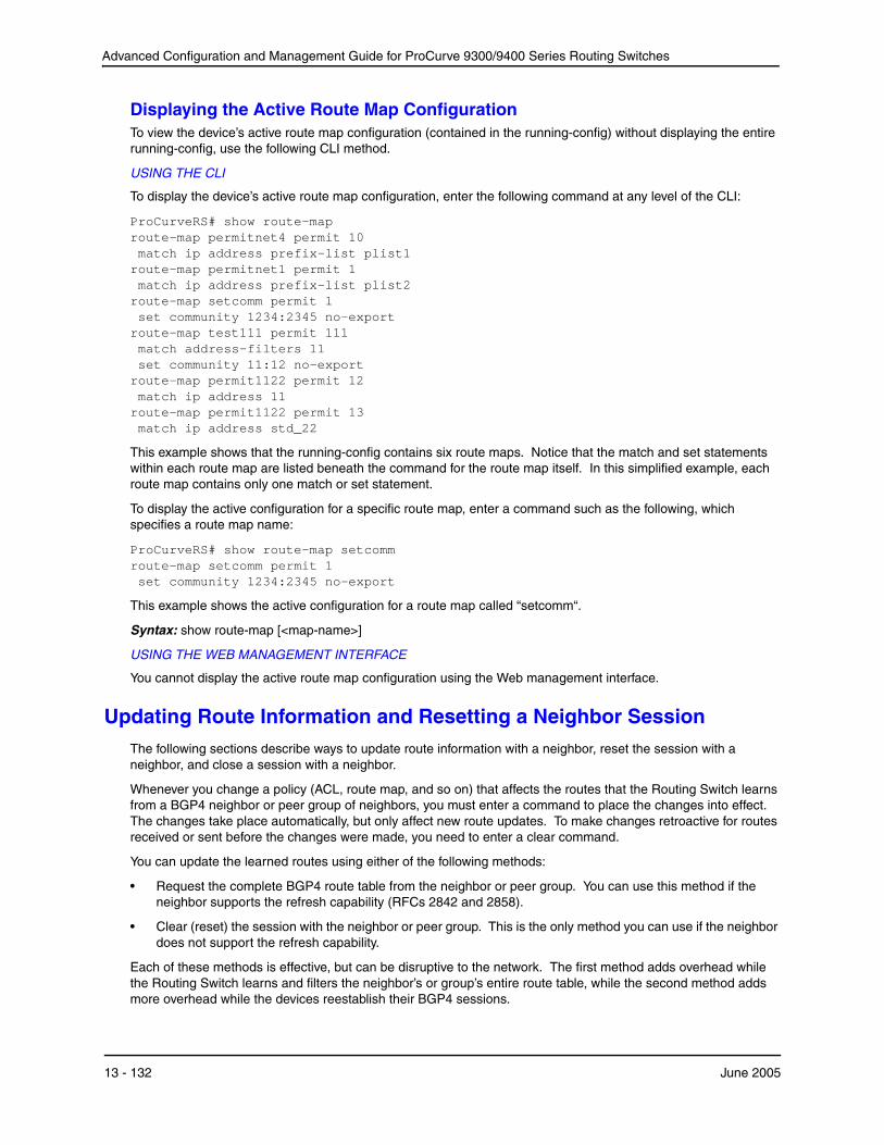
Advanced Configuration and Management Guide for ProCurve 9300/9400 Series Routing Switches
Displaying the Active Route Map Configuration To view the device’s active route map configuration (contained in the running-config) without displaying the entire running-config, use the following CLI method.
USING THE CLI
To display the device’s active route map configuration, enter the following command at any level of the CLI:
ProCurveRS# show route-map route-map permitnet4 permit 10match ip address prefix-list plist1
route-map permitnet1 permit 1 match ip address prefix-list plist2
route-map setcomm permit 1 set community 1234:2345 no-export
route-map test111 permit 111 match address-filters 11 set community 11:12 no-export
route-map permit1122 permit 12 match ip address 11
route-map permit1122 permit 13 match ip address std_22
This example shows that the running-config contains six route maps. Notice that the match and set statements within each route map are listed beneath the command for the route map itself. In this simplified example, each route map contains only one match or set statement.
To display the active configuration for a specific route map, enter a command such as the following, which specifies a route map name:
ProCurveRS# show route-map setcomm route-map setcomm permit 1 set community 1234:2345 no-export
This example shows the active configuration for a route map called “setcomm“.
Syntax: show route-map [<map-name>]
USING THE WEB MANAGEMENT INTERFACE
You cannot display the active route map configuration using the Web management interface.
Updating Route Information and Resetting a Neighbor Session The following sections describe ways to update route information with a neighbor, reset the session with a neighbor, and close a session with a neighbor.
Whenever you change a policy (ACL, route map, and so on) that affects the routes that the Routing Switch learns from a BGP4 neighbor or peer group of neighbors, you must enter a command to place the changes into effect. The changes take place automatically, but only affect new route updates. To make changes retroactive for routes received or sent before the changes were made, you need to enter a clear command.
You can update the learned routes using either of the following methods:
• Request the complete BGP4 route table from the neighbor or peer group. You can use this method if the neighbor supports the refresh capability (RFCs 2842 and 2858).
• Clear (reset) the session with the neighbor or peer group. This is the only method you can use if the neighbor does not support the refresh capability.
Each of these methods is effective, but can be disruptive to the network. The first method adds overhead while the Routing Switch learns and filters the neighbor’s or group’s entire route table, while the second method adds more overhead while the devices reestablish their BGP4 sessions.
13 - 132 June 2005
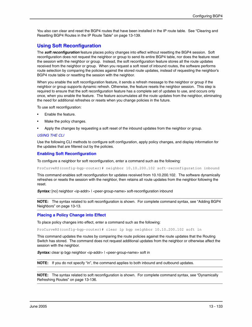
Configuring BGP4
You also can clear and reset the BGP4 routes that have been installed in the IP route table. See “Clearing and Resetting BGP4 Routes in the IP Route Table” on page 13-139.
Using Soft Reconfiguration The soft reconfiguration feature places policy changes into effect without resetting the BGP4 session. Soft reconfiguration does not request the neighbor or group to send its entire BGP4 table, nor does the feature reset the session with the neighbor or group. Instead, the soft reconfiguration feature stores all the route updates received from the neighbor or group. When you request a soft reset of inbound routes, the software performs route selection by comparing the policies against the stored route updates, instead of requesting the neighbor’s BGP4 route table or resetting the session with the neighbor.
When you enable the soft reconfiguration feature, it sends a refresh message to the neighbor or group if the neighbor or group supports dynamic refresh. Otherwise, the feature resets the neighbor session. This step is required to ensure that the soft reconfiguration feature has a complete set of updates to use, and occurs only once, when you enable the feature. The feature accumulates all the route updates from the neighbor, eliminating the need for additional refreshes or resets when you change policies in the future.
To use soft reconfiguration:
• Enable the feature.
• Make the policy changes.
• Apply the changes by requesting a soft reset of the inbound updates from the neighbor or group.
USING THE CLI
Use the following CLI methods to configure soft configuration, apply policy changes, and display information for the updates that are filtered out by the policies.
Enabling Soft Reconfiguration
To configure a neighbor for soft reconfiguration, enter a command such as the following:
ProCurveRS(config-bgp-router)# neighbor 10.10.200.102 soft-reconfiguration inbound
This command enables soft reconfiguration for updates received from 10.10.200.102. The software dynamically refreshes or resets the session with the neighbor, then retains all route updates from the neighbor following the reset.
Syntax: [no] neighbor <ip-addr> | <peer-group-name> soft-reconfiguration inbound
NOTE: The syntax related to soft reconfiguration is shown. For complete command syntax, see “Adding BGP4 Neighbors” on page 13-13.
Placing a Policy Change into Effect
To place policy changes into effect, enter a command such as the following:
ProCurveRS(config-bgp-router)# clear ip bgp neighbor 10.10.200.102 soft in
This command updates the routes by comparing the route policies against the route updates that the Routing Switch has stored. The command does not request additional updates from the neighbor or otherwise affect the session with the neighbor.
Syntax: clear ip bgp neighbor <ip-addr> | <peer-group-name> soft in
NOTE: If you do not specify “in”, the command applies to both inbound and outbound updates.
NOTE: The syntax related to soft reconfiguration is shown. For complete command syntax, see “Dynamically Refreshing Routes” on page 13-136.
June 2005 13 - 133
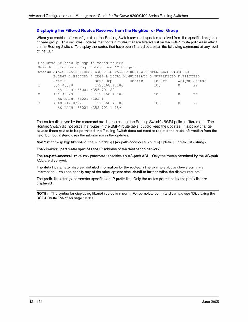
Advanced Configuration and Management Guide for ProCurve 9300/9400 Series Routing Switches
Displaying the Filtered Routes Received from the Neighbor or Peer Group
When you enable soft reconfiguration, the Routing Switch saves all updates received from the specified neighbor or peer group. This includes updates that contain routes that are filtered out by the BGP4 route policies in effect on the Routing Switch. To display the routes that have been filtered out, enter the following command at any level of the CLI:
ProCurveRS# show ip bgp filtered-routesSearching for matching routes, use ^C to quit...Status A:AGGREGATE B:BEST b:NOT-INSTALLED-BEST C:CONFED_EBGP D:DAMPED
E:EBGP H:HISTORY I:IBGP L:LOCAL M:MULTIPATH S:SUPPRESSED F:FILTERED
1 Prefix Next Hop
3.0.0.0/8 192.168.4.106 AS_PATH: 65001 4355 701 80
Metric LocPrf 100
Weight Status 0 EF
2 4.0.0.0/8 192.168.4.106 AS_PATH: 65001 4355 1
100 0 EF
3 4.60.212.0/22 192.168.4.106 AS_PATH: 65001 4355 701 1 189
100 0 EF
The routes displayed by the command are the routes that the Routing Switch’s BGP4 policies filtered out. The Routing Switch did not place the routes in the BGP4 route table, but did keep the updates. If a policy change causes these routes to be permitted, the Routing Switch does not need to request the route information from the neighbor, but instead uses the information in the updates.
Syntax: show ip bgp filtered-routes [<ip-addr>] | [as-path-access-list <num>] | [detail] | [prefix-list <string>]
The <ip-addr> parameter specifies the IP address of the destination network.
The as-path-access-list <num> parameter specifies an AS-path ACL. Only the routes permitted by the AS-path ACL are displayed.
The detail parameter displays detailed information for the routes. (The example above shows summary information.) You can specify any of the other options after detail to further refine the display request.
The prefix-list <string> parameter specifies an IP prefix list. Only the routes permitted by the prefix list are displayed.
NOTE: The syntax for displaying filtered routes is shown. For complete command syntax, see “Displaying the BGP4 Route Table” on page 13-120.
13 - 134 June 2005
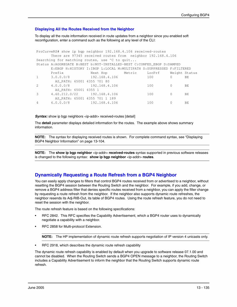
Configuring BGP4
Displaying All the Routes Received from the Neighbor
To display all the route information received in route updates from a neighbor since you enabled soft reconfiguration, enter a command such as the following at any level of the CLI:
ProCurveRS# show ip bgp neighbor 192.168.4.106 received-routes There are 97345 received routes from neighbor 192.168.4.106
Searching for matching routes, use ^C to quit...Status A:AGGREGATE B:BEST b:NOT-INSTALLED-BEST C:CONFED_EBGP D:DAMPED
E:EBGP H:HISTORY I:IBGP L:LOCAL M:MULTIPATH S:SUPPRESSED F:FILTERED
1 Prefix Next Hop
3.0.0.0/8 192.168.4.106 AS_PATH: 65001 4355 701 80
Metric LocPrf 100
Weight Status 0 BE
2 4.0.0.0/8 192.168.4.106 AS_PATH: 65001 4355 1
100 0 BE
3 4.60.212.0/22 192.168.4.106 AS_PATH: 65001 4355 701 1 189
100 0 BE
4 6.0.0.0/8 192.168.4.106 100 0 BE
Syntax: show ip bgp neighbors <ip-addr> received-routes [detail]
The detail parameter displays detailed information for the routes. The example above shows summary information.
NOTE: The syntax for displaying received routes is shown. For complete command syntax, see “Displaying BGP4 Neighbor Information” on page 13-104.
NOTE: The show ip bgp neighbor <ip-addr> received-routes syntax supported in previous software releases is changed to the following syntax: show ip bgp neighbor <ip-addr> routes.
Dynamically Requesting a Route Refresh from a BGP4 Neighbor You can easily apply changes to filters that control BGP4 routes received from or advertised to a neighbor, without resetting the BGP4 session between the Routing Switch and the neighbor. For example, if you add, change, or remove a BGP4 address filter that denies specific routes received from a neighbor, you can apply the filter change by requesting a route refresh from the neighbor. If the neighbor also supports dynamic route refreshes, the neighbor resends its Adj-RIB-Out, its table of BGP4 routes. Using the route refresh feature, you do not need to reset the session with the neighbor.
The route refresh feature is based on the following specifications:
• RFC 2842. This RFC specifies the Capability Advertisement, which a BGP4 router uses to dynamically negotiate a capability with a neighbor.
• RFC 2858 for Multi-protocol Extension.
NOTE: The HP implementation of dynamic route refresh supports negotiation of IP version 4 unicasts only.
• RFC 2918, which describes the dynamic route refresh capability
The dynamic route refresh capability is enabled by default when you upgrade to software release 07.1.00 and cannot be disabled. When the Routing Switch sends a BGP4 OPEN message to a neighbor, the Routing Switch includes a Capability Advertisement to inform the neighbor that the Routing Switch supports dynamic route refresh.
June 2005 13 - 135

Advanced Configuration and Management Guide for ProCurve 9300/9400 Series Routing Switches
NOTE: The option for dynamically refreshing routes received from a neighbor requires the neighbor to support dynamic route refresh. If the neighbor does not support this feature, the option does not take effect and the software displays an error message. The option for dynamically re-advertising routes to a neighbor does not require the neighbor to support dynamic route refresh.
To use the dynamic refresh feature, use either of the following methods.
Dynamically Refreshing Routes
The following sections describe how to dynamically refresh BGP4 routes to place new or changed filters into effect.
USING THE CLI
To request a dynamic refresh of all routes from a neighbor, enter a command such as the following:
ProCurveRS(config-bgp-router)# clear ip bgp neighbor 192.168.1.170 soft in
This command asks the neighbor to send its BGP4 table (Adj-RIB-Out) again. The Routing Switch applies its filters to the incoming routes and adds, modifies, or removes BGP4 routes as necessary.
Syntax: clear ip bgp neighbor all | <ip-addr> | <peer-group-name> | <as-num> [soft-outbound | soft [in | out]]
The all | <ip-addr> | <peer-group-name> | <as-num> specifies the neighbor. The <ip-addr> parameter specifies a neighbor by its IP interface with the Routing Switch. The <peer-group-name> specifies all neighbors in a specific peer group. The <as-num> parameter specifies all neighbors within the specified AS. The all parameter specifies all neighbors.
The soft-outbound parameter updates all outbound routes by applying the new or changed filters, but sends only the existing routes affected by the new or changed filters to the neighbor.
The soft [in | out] parameter specifies whether you want to refresh the routes received from the neighbor or sent to the neighbor:
• soft in does one of the following:
• If you enabled soft reconfiguration for the neighbor or peer group, soft in updates the routes by comparing the route policies against the route updates that the Routing Switch has stored. Soft reconfiguration does not request additional updates from the neighbor or otherwise affect the session with the neighbor. See “Using Soft Reconfiguration” on page 13-133.
• If you did not enable soft reconfiguration, soft in requests the neighbor’s entire BGP4 route table (Adj-RIB-Out), then applies the filters to add, change, or exclude routes.
• If a neighbor does not support dynamic refresh, soft in resets the neighbor session.
• soft out updates all outbound routes, then sends the Routing Switch’s entire BGP4 route table (Adj-RIB-Out) to the neighbor, after changing or excluding the routes affected by the filters.
If you do not specify in or out, the Routing Switch performs both options.
NOTE: The soft-outbound parameter updates all outbound routes by applying the new or changed filters, but sends only the existing routes affected by the new or changed filters to the neighbor. The soft out parameter updates all outbound routes, then sends the Routing Switch’s entire BGP4 route table (Adj-RIB-Out) to the neighbor, after changing or excluding the routes affected by the filters. Use soft-outbound if only the outbound policy is changed.
To dynamically resend all the Routing Switch’s BGP4 routes to a neighbor, enter a command such as the following:
ProCurveRS(config-bgp-router)# clear ip bgp neighbor 192.168.1.170 soft out
This command applies its filters for outgoing routes to the Routing Switch’s BGP4 route table (Adj-RIB-Out), changes or excludes routes accordingly, then sends the resulting Adj-RIB-Out to the neighbor.
13 - 136 June 2005

Configuring BGP4
NOTE: The ProCurve Routing Switch does not automatically update outbound routes using a new or changed outbound policy or filter when a session with the neighbor goes up or down. Instead, the Routing Switch applies a new or changed policy or filter when a route is placed in the outbound queue (Adj-RIB-Out).
To place a new or changed outbound policy or filter into effect, you must enter a clear ip bgp neighbor command regardless of whether the neighbor session is up or down. You can enter the command without optional parameters or with the soft out or soft-outbound option. Either way, you must specify a parameter for the neighbor (<ip-addr>, <as-num>, <peer-group-name>, or all).
USING THE WEB MANAGEMENT INTERFACE
You cannot perform these reset procedures using the Web management interface.
Displaying Dynamic Refresh Information
You can use the show ip bgp neighbors command to display information for dynamic refresh requests. For each neighbor, the display lists the number of dynamic refresh requests the Routing Switch has sent to or received from the neighbor and indicates whether the Routing Switch received confirmation from the neighbor that the neighbor supports dynamic route refresh.
The RefreshCapability field indicates whether this Routing Switch has received confirmation from the neighbor that the neighbor supports the dynamic refresh capability. The statistics in the Message Sent and Message
June 2005 13 - 137

Advanced Configuration and Management Guide for ProCurve 9300/9400 Series Routing Switches
1
Received rows under Refresh-Req indicate how many dynamic refreshes have been sent to and received from the neighbor. The statistic is cumulative across sessions.
ProCurveRS(config-bgp-router)# show ip bgp neighbor 10.4.0.2 IP Address: 10.4.0.2, AS: 5 (EBGP), RouterID: 100.0.0.1 Description: neighbor 10.4.0.2
State: ESTABLISHED, Time: 0h1m0s, KeepAliveTime: 0, HoldTime: 0 PeerGroup: pg1 Mutihop-EBGP: yes, ttl: 1 RouteReflectorClient: yes SendCommunity: yes NextHopSelf: yes DefaultOriginate: yes (default sent) MaximumPrefixLimit: 90000 RemovePrivateAs: : yes RefreshCapability: Received
Route Filter Policies: Distribute-list: (out) 20 Filter-list: (in) 30 Prefix-list: (in) pf1 Route-map: (in) setnp1 (out) setnp2
Messages: Open Update KeepAlive Notification Refresh-Req Sent : 1 1 1 0 0
Received: 1 8 1 0 0 Last Update Time: NLRI Withdraw NLRI Withdraw
Tx: 0h0m59s --- Rx: 0h0m59s --- Last Connection Reset Reason:Unknown
Notification Sent: Unspecified Notification Received: Unspecified
TCP Connection state: ESTABLISHED Byte Sent: 115, Received: 492 Local host: 10.4.0.1, Local Port: 179 Remote host: 10.4.0.2, Remote Port: 8053 ISentSeq: 52837276 SendNext: 52837392 TotUnAck: 0 TotSent: 116 ReTrans: 0 UnAckSeq: 52837392 IRcvSeq: 2155052043 RcvNext: 2155052536 SendWnd: 16384 TotalRcv: 493 DupliRcv: 0 RcvWnd: 16384 SendQue: 0 RcvQue: 0 CngstWnd: 1460
Closing or Resetting a Neighbor Session You can close a neighbor session or resend route updates to a neighbor.
If you make changes to filters or route maps and the neighbor does not support dynamic route refresh, use these methods to ensure that neighbors contain only the routes you want them to contain.
• If you close a neighbor session, the Routing Switch and the neighbor clear all the routes they learned from each other. When the Routing Switch and neighbor establish a new BGP4 session, they exchange route tables again. Use this method if you want the Routing Switch to relearn routes from the neighbor and resend its own route table to the neighbor.
• If you use the soft-outbound option, the Routing Switch compiles a list of all the routes it would normally send to the neighbor at the beginning of a session. However, before sending the updates, the ProCurve Routing Switch also applies the filters and route maps you have configured to the list of routes. If the filters or route maps result in changes to the list of routes, the Routing Switch sends updates to advertise, change, or even withdraw routes on the neighbor as needed. This ensures that the neighbor receives only the routes you want it to contain. Even if the neighbor already contains a route learned from the Routing Switch that you later decided to filter out, using the soft-outbound option removes that route from the neighbor.
13 - 138 June 2005

Configuring BGP4
You can specify a single neighbor or a peer group.
USING THE CLI
To close a neighbor session and thus flush all the routes exchanged by the Routing Switch and the neighbor, enter the following command:
ProCurveRS# clear ip bgp neighbor all
Syntax: clear ip bgp neighbor all | <ip-addr> | <peer-group-name> | <as-num> [soft-outbound | soft [in | out]]
The all | <ip-addr> | <peer-group-name> | <as-num> specifies the neighbor. The <ip-addr> parameter specifies a neighbor by its IP interface with the Routing Switch. The <peer-group-name> specifies all neighbors in a specific peer group. The <as-num> parameter specifies all neighbors within the specified AS. The all parameter specifies all neighbors.
To resend routes to a neighbor without closing the neighbor session, enter a command such as the following:
ProCurveRS# clear ip bgp neighbor 10.0.0.1 soft out
USING THE WEB MANAGEMENT INTERFACE
To resend route information to a neighbor, use the following procedure:
1. Log on to the device using a valid user name and password for read-write access. The System configuration panel is displayed.
2. Click on the plus sign next to Command in the tree view to expand the list of command options.
3. Click on the Clear link to display the Clear panel.
4. Select BGP Neighbor Soft-Outbound.
5. Use the default value All to resend the BGP4 route table to all neighbors or select a neighbor from the field’s pulldown menu.
6. Click the Apply button to implement the change.
Clearing and Resetting BGP4 Routes in the IP Route Table To clear BGP4 routes from the IP route table and reset the routes, enter a command such as the following:
ProCurveRS# clear ip bgp routes
Syntax: clear ip bgp routes [<ip-addr>/<prefix-length>]
NOTE: The clear ip bgp routes command has the same effect as the clear ip route command, but applies only to routes that come from BGP4.
Clearing Traffic Counters You can clear the counters (reset them to 0) for BGP4 messages. To do so, use one of the following methods.
USING THE CLI
To clear the BGP4 message counter for all neighbors, enter the following command:
ProCurveRS# clear ip bgp traffic
Syntax: clear ip bgp traffic
To clear the BGP4 message counter for a specific neighbor, enter a command such as the following:
ProCurveRS# clear ip bgp neighbor 10.0.0.1 traffic
To clear the BGP4 message counter for all neighbors within a peer group, enter a command such as the following:
ProCurveRS# clear ip bgp neighbor PeerGroup1 traffic
June 2005 13 - 139

Advanced Configuration and Management Guide for ProCurve 9300/9400 Series Routing Switches
Syntax: clear ip bgp neighbor all | <ip-addr> | <peer-group-name> | <as-num> traffic
The all | <ip-addr> | <peer-group-name> | <as-num> specifies the neighbor. The <ip-addr> parameter specifies a neighbor by its IP interface with the Routing Switch. The <peer-group-name> specifies all neighbors in a specific peer group. The <as-num> parameter specifies all neighbors within the specified AS. The all parameter specifies all neighbors.
USING THE WEB MANAGEMENT INTERFACE
1. Log on to the device using a valid user name and password for read-write access. The System configuration panel is displayed.
2. Click on the plus sign next to Command in the tree view to expand the list of command options.
3. Click on the Clear link to display the Clear panel.
4. Select one of the following options:
• BGP Neighbor Traffic – clears the BGP4 message counters for all neighbors (the default) or a neighbor you select from the pulldown menu.
• BGP Neighbor – clears the BGP4 message counters for all neighbors (the default) or a neighbor you select from the pulldown menu.
5. Click the Apply button to implement the change.
Clearing Route Flap Dampening Statistics To clear route flap dampening statistics, use the following CLI method.
NOTE: Clearing the dampening statistics for a route does not change the dampening status of the route.
USING THE CLI
To clear all the route dampening statistics, enter the following command at any level of the CLI:
ProCurveRS# clear ip bgp flap-statistics
Syntax: clear ip bgp flap-statistics [regular-expression <regular-expression> | <address> <mask> | neighbor <ipaddr>]
The parameters are the same as those for the show ip bgp flap-statistics command (except the longerprefixes option is not supported). See “Displaying Route Flap Dampening Statistics” on page 13-94.
NOTE: The clear ip bgp damping command not only clears statistics but also un-suppresses the routes. See “Displaying Route Flap Dampening Statistics” on page 13-94.
USING THE WEB MANAGEMENT INTERFACE
You cannot clear dampening statistics using the Web management interface.
Removing Route Flap Dampening You can un-suppress routes by removing route flap dampening from the routes. The Routing Switch allows you to un-suppress all routes at once or un-suppress individual routes.
To un-suppress routes, use either of the following methods.
USING THE CLI
To un-suppress all the suppressed routes, enter the following command at the Privileged EXEC level of the CLI:
ProCurveRS# clear ip bgp damping
Syntax: clear ip bgp damping [<ip-addr> <ip-mask>]
The <ip-addr> parameter specifies a particular network.
13 - 140 June 2005

Configuring BGP4
The <ip-mask> parameter specifies the network’s mask.
To un-suppress a specific route, enter a command such as the following:
ProCurveRS# clear ip bgp damping 209.157.22.0 255.255.255.0
This command un-suppresses only the route(s) for network 209.157.22.0/24.
USING THE WEB MANAGEMENT INTERFACE
1. Log on to the device using a valid user name and password for read-write access. The System configuration panel is displayed.
2. Click on the plus sign next to Command in the tree view to expand the list of command options.
3. Click on the Clear link to display the Clear panel.
4. Select the checkbox next to BGP Dampening.
5. Specify the routes from which you want to remove dampening:
• To clear dampening for all routes, select the All option.
• To clear dampening for a specific route, select IP, then enter the network address and sub-net mask in the IP and Mask fields.
6. Click the Apply button to implement the change.
Clearing Diagnostic Buffers The Routing Switch stores the following BGP4 diagnostic information in buffers:
• The first 400 bytes of the last packet that contained an error
• The last NOTIFICATION message either sent or received by the Routing Switch
To display these buffers, use options with the show ip bgp neighbors command. See “Displaying BGP4 Neighbor Information” on page 13-104.
This information can be useful if you are working with HP Technical Support to resolve a problem. The buffers do not identify the system time when the data was written to the buffer. If you want to ensure that diagnostic data in a buffer is recent, you can clear the buffers. You can clear the buffers for a specific neighbor or for all neighbors.
If you clear the buffer containing the first 400 bytes of the last packet that contained errors, all the bytes are changed to zeros. The Last Connection Reset Reason field of the BGP neighbor table also is cleared.
If you clear the buffer containing the last NOTIFICATION message sent or received, the buffer contains no data.
You can clear the buffers for all neighbors, for an individual neighbor, or for all the neighbors within a specific peer group.
USING THE CLI
To clear these buffers for neighbor 10.0.0.1, enter the following commands:
ProCurveRS# clear ip bgp neighbor 10.0.0.1 last-packet-with-errorProCurveRS# clear ip bgp neighbor 10.0.0.1 notification-errors
Syntax: clear ip bgp neighbor all | <ip-addr> | <peer-group-name> | <as-num>last-packet-with-error | notification-errors
The all | <ip-addr> | <peer-group-name> | <as-num> specifies the neighbor. The <ip-addr> parameter specifies a neighbor by its IP interface with the Routing Switch. The <peer-group-name> specifies all neighbors in a specific peer group. The <as-num> parameter specifies all neighbors within the specified AS. The all parameter specifies all neighbors.
USING THE WEB MANAGEMENT INTERFACE
1. Log on to the device using a valid user name and password for read-write access. The System configuration panel is displayed.
June 2005 13 - 141
Advanced Configuration and Management Guide for ProCurve 9300/9400 Series Routing Switches
2. Click on the plus sign next to Command in the tree view to expand the list of command options.
3. Click on the Clear link to display the Clear panel.
4. Select one of the following:
• BGP Neighbor Last Packet with Error – Clears the buffer containing the first 400 bytes of the last BGP4 packet that contained an error.
• BGP Neighbor Notification Error – Clears the buffer containing the last NOTIFICATION message sent or received.
5. Click the Apply button to implement the change.
13 - 142 June 2005