Embed Size (px)
Citation preview

OFFICE OF STRUCTURES STRUCTURAL DETAIL MANUAL
Chapter 11 - Structural Repairs
SECTION 03
JACKING SYSTEMS (SR-JS)

OFFICE OF STRUCTURES STRUCTURAL DETAIL MANUAL
Chapter 11 - Structural Repairs
Section 03 – Jacking Systems
SUB-SECTION 01
JACKING BEAM (SR-JS(JB))

* FOR OFFICE USE ONLY *
* GUIDE SHEET FOR PLAN DEVELOPMENT ONLY - DO NOT INCLUDE THIS SHEET IN CONTRACT PLANS *
DESIGN GUIDELINES FOR JACKING BEAMS
*
*
1 1
A five percent increase to the dead load beam reaction is required for
possible. The connection shall be designed in bearing with the reduced
Minimum fillet weld size shall be 5/16 ’’.
1)
2)
3)
4)
6)
7)
The temporary jacking system is to be designed at operating stress levels.
deck stiffness.
Minimum stiffener and connection plate thickness shall be 1/2 ’’.
5) Designers should attempt to minimize the number of different jacking systems
for the bridge by designing a system that will work in multiple locations.
8)
9)
10)
DATE:
STATE HIGHWAY ADMINISTRATION
DEPARTMENT OF TRANSPORTATION
STATE OF MARYLAND
SHEET OF
APPROVAL
ST
RU
CT
UR
AL
RE
PA
IRS
Bolts shall be ASTM A 325 with the threads included in the shear plane if
root area. ASTM A 490 bolts are acceptable.
OFFICE OF STRUCTURES
DIRECTOR
OFFICE OF STRUCTURES
LOAD
(X)
X < 35K
35K < X < 45K
45K < X < 60K
60K < X < 80K
BEAM
W 12 x 26
W 14 x 26
W 18 x 35
W 18 x 35
CONNECTION
PLATE
1/2 ’’ x 9’’
1/2 ’’ x 11’’
1/2 ’’ x 14 1/2 ’’
1/2 ’’ x 18’’
Load (X) is dead load and live load plus impact at
the bolts
JACKING BEAMDESIGN GUIDELINES
BOLTS
3 - 7/8 ’’ A 325
3 - 1’’ A 325
4 - 1’’ A 325
4 - 1’’ A 490
Avoid bent connection plates where possible. If the skew angle does not allow
placing straight connection plates from the existing stiffener to the web,
attach the connection plate full height to the existing web and design it as
a stiffener. Place it far enough from the existing stiffener to allow welding
the connection plate to the web and still have full bearing under the jacking
system.
The jack stand can only accomodate a jack with a diameter of 6’’ or less.
Most jacks greater than 75 tons will require a different stand.
The possibility of shifting traffic off of the stringer to be jacked should be
discussed with the ADE-Traffic. This would allow designing for only dead load.
When designing a jacking beam the designer may want to start with
the following trial sections:
SR-JS(JB)-101
1.0
VERSION
DETAIL NO.
06/28/2017

Existing diaphragm
2
22 Jack Offset Existing interior
stringer
Jack, stiffener, jack
support assembly, etc.
EXTERIOR - JACKING BEAM
Scale : None
1.
2.
3.
4.
5.
6.
1 6
EXTERIOR BEAM JACKING DETAILS
Minimum Section Modulus
Minimum Web Thickness
Maximum Jack Force
JACKING BEAM TABLE
Jack Offset
Jacking Beam
Steel Grade
Stiffener Plate Size
Minimum Cross Sectional Web Area
7.
DATE:
STATE HIGHWAY ADMINISTRATION
DEPARTMENT OF TRANSPORTATION
STATE OF MARYLAND
SHEET OF
APPROVAL
Location:Size:
ST
RU
CT
UR
AL
RE
PA
IRS
OFFICE OF STRUCTURES
DIRECTOR
OFFICE OF STRUCTURES
5/16
5/16 See typical
connection detail
See jack support
assembly details
Stiffener plate
(both sides)
clip corners
3/4 ’’ x 3/4 ’’ (typ.)
Existingexterior stringer(stringer tobe raised)
Existingstiffener(typ.)
Jacking beam(set level)
Notes:
Jacking beams do not have to be new, but shall be in good condition.
The jack shall not be used to support load during bearing repairs.
Jacking beams shall be placed level unless otherwise noted.
The Contractor has the option of submitting another method of jacking to
the Engineer for approval. The design shall be done by a PE registered in Md.
Jacking beams shall be kept low to minimize height of stacked plates or the
HP column jack support.
Anchor bolt nuts may need to be loosened at the exterior and adjacent
interior stringers to allow the stringer to rise.
Stringers shall not be raised more than 1/8 ’’ above its existing elevation.
SR-JS(JB)-102
1.0
VERSION
DETAIL NO.
06/28/2017

2
Ex
isti
ng
sti
ffen
er
(ty
p.)
Exis
ting d
iaphra
gm
See j
ack
su
pp
ort
assem
bly
deta
il
2Jack
, sti
ffen
er,
jack
su
pp
ort
assem
bly
, etc
.
Jack
Offset
2E
xis
tin
g i
nte
rio
r
str
inger (
str
inger
to b
e r
ais
ed
)
2 str
inger
See t
yp
ical
co
nn
ecti
on
deta
il
Sti
ffen
er p
late
(both
sid
es)
cli
p c
orners
3/4
’’
x 3/4
’’
(typ.)
INT
ER
IOR
- J
AC
KIN
G B
EA
M
Scale
: N
one
2 6
INTERIOR BEAM JACKING DETAILS
(Ty
p.)
E
xis
ting
str
inger
Ex
isti
ng
Jack
ing
beam
(set
level)
1.
2.
3.
4.
5.
6.
Min
imu
m S
ecti
on
Mo
du
lus
Min
imu
m W
eb
Th
ick
ness
Maxim
um
Jack F
orc
e
JAC
KIN
G B
EA
M T
AB
LE
Jack
Offset
Jackin
g B
eam
Locati
on:
Ste
el
Gra
de
Sti
ffen
er P
late
Siz
e
Min
imu
m C
ross S
ecti
on
al
Web
Are
a
7.
DATE:
STATE HIGHWAY ADMINISTRATION
DEPARTMENT OF TRANSPORTATION
STATE OF MARYLAND
SHEET OF
APPROVAL
No
tes:
Jack
ing
beam
s d
o n
ot
hav
e t
o b
e n
ew
, b
ut
sh
all
b
e i
n g
oo
d c
on
dit
ion
.
The j
ack s
hall
not
be u
sed t
o s
upport
load d
urin
g b
earin
g r
epair
s.
Jack
ing
beam
s s
hall
b
e p
laced
lev
el
un
less o
therw
ise n
ote
d.
The C
ontr
acto
r h
as t
he o
pti
on o
f s
ubm
itti
ng a
noth
er m
eth
od o
f j
ackin
g t
o
the E
ng
ineer f
or a
pp
ro
val.
Th
e d
esig
n s
hall
b
e d
on
e b
y a
PE
reg
iste
red
in
Md
.
Jackin
g b
eam
s s
hall
be k
ept
low
to m
inim
ize h
eig
ht
of s
tacked p
late
s o
r t
he
HP
colu
mn j
ack s
upport
.
An
ch
or b
olt
nu
ts m
ay
need
to
be l
oo
sen
ed
at
the e
xte
rio
r a
nd
ad
jacen
t
inte
rio
r s
trin
gers t
o a
llo
w t
he s
trin
ger t
o r
ise.
Str
ingers s
hall
not
be r
ais
ed m
ore t
han 1/8
’’ a
bove i
ts e
xis
ting e
levati
on.
Siz
e:
ST
RU
CT
UR
AL
RE
PA
IRS
OFFICE OF STRUCTURES
DIRECTOR
OFFICE OF STRUCTURES
5/16
5/16
SR-JS(JB)-102
1.0
VERSION
DETAIL NO.
06/28/2017

Existing stiffener
PLAN
45^
Jacking beam
Bolts2
Bolts2
New connection plate
Jacking beam
Existing stiffener
Equal space
Existing stringer
Bo
lt
Sp
acin
g
1’’ 2’’ 2’’ 1/2 ’’
2’’ 2’’ 1/2 ’’
Mitre plate to match web
New connection plate
2 Existing stringer
Scale : None
TYPICAL SKEWED CONNECTION DETAIL
ELEVATION
SKEWED CONNECTION DETAILS
3 6
1 3/4 ’’ for 1’’ bolts
1 1/2 ’’ for 7/8 ’’ bolts
DATE:
STATE HIGHWAY ADMINISTRATION
DEPARTMENT OF TRANSPORTATION
STATE OF MARYLAND
SHEET OF
APPROVAL
CONNECTION DETAILS
Location:
ST
RU
CT
UR
AL
RE
PA
IRS
Materials:
Connection Plate Size
Connection Plate Weld
Number of Bolts
Bolt (Type and Size)
Bolt Spacing c/c
Existing Stiffener Plate Size
Steel Grade
OFFICE OF STRUCTURES
DIRECTOR
OFFICE OF STRUCTURES
Cut flange
as shown
(if required)
Notes:
Any steel that has been welded to the
existing bridge shall remain in place.
The repaired area and any other areas
damaged shall be repaired in
conformance with 430.
SR-JS(JB)-102
1.0
VERSION
DETAIL NO.
06/28/2017

4 6
90^ CONNECTION DETAILS
PLAN
Bolts2
New connection plate
Jacking beam
Existing stiffener
Equal space
Bo
lt
Sp
acin
g
2’’ 2’’ 1/2 ’’
2 Existing stringer
Scale : None
ELEVATION
Existing stringer1’’ 2’’ 2’’
45^
Jacking beam
Existing stiffener
Bolts2
New connection plate
TYPICAL 90^ CONNECTION DETAIL
DATE:
STATE HIGHWAY ADMINISTRATION
DEPARTMENT OF TRANSPORTATION
STATE OF MARYLAND
SHEET OF
APPROVAL
ST
RU
CT
UR
AL
RE
PA
IRS
CONNECTION DETAILS
Location:Materials:
Connection Plate Size
Connection Plate Weld
Number of Bolts
Bolt (Type and Size)
Bolt Spacing c/c
Existing Stiffener Plate Size
Steel Grade
1 3/4 ’’ for 1’’ bolts
1 1/2 ’’ for 7/8 ’’ bolts
OFFICE OF STRUCTURES
DIRECTOR
OFFICE OF STRUCTURES
Cut flange
as shown
(if required)
Bevel connection plate
to match existing weld.
1/2 ’’
min.
Notes:
Any steel that has been welded to the
existing bridge shall remain in place.
The repaired area and any other areas
damaged shall be repaired in
conformance with 430.
SR-JS(JB)-102
1.0
VERSION
DETAIL NO.
06/28/2017

2
Top of jacking surface
AA
2
Top of jacking surface
Scale : None
Scale : None
1.
2.
3.
4.
5.
5 6
typ.
ELEVATION
JACK SUPPORT USING STACKED PLATES
Jacking beam
1’’ x 12’’ x 1’-0’’
See jack support assembly detail
JACK SUPPORT ASSEMBLY
ELEVATION
ALTERNATE COLUMN SPACER DETAIL
ST
RU
CT
UR
AL
RE
PA
IRS
DATE:
STATE HIGHWAY ADMINISTRATION
DEPARTMENT OF TRANSPORTATION
STATE OF MARYLAND
SHEET OF
APPROVAL
OFFICE OF STRUCTURES
DIRECTOR
OFFICE OF STRUCTURES
5/16
bearing plate
1’’ x 12’’ x 1’-0’’ base plate
HP8 x 36 column spacer
Jack, plates, and
jack support assembly
jack, plates, stiffener
and jack support assembly
Nonshrink grout
leveling pad
(as required)
Nonshrink grout
leveling pad
(as required)
Stacked plates height
as required (12’’ max.)
Stiffener plate (both sides)
clip corners 3/4 ’’ x 3/4 ’’ (typ.)
1/2 ’’ x 12’’ x 1’-0’’ plates
(or thicker).
Note:
The contractor may use the column
spacer instead of stacked plates.
The column spacer shall be used for
heights greater than 12’’ to a maximum
of 5’-0’’ high.
1’’ x 12’’ x 1’-0’’ base plate
of jack support assembly
1’’ x 12’’ x 1’-0’’
masonry plate
Grease mating surfaces
as neededTack weld shim plate as
needed in field, see detail
Notes:
Minimum thickness of the grout leveling pad
shall be as recommended by manufacturer.
Jack shall be centered under jacking
beam web and stiffeners.
Stacked plates shall not exceed 12’’
high.
HP8 x 36 column spacer shall not
exceed 5’-0’’ high.
All material to be ASTM A 709
Grade 36 or Grade 50 as approved by
the engineer.
Tack
typ.
SR-JS(JB)-102
1.0
VERSION
DETAIL NO.
06/28/2017

2
2
Jack
Shim plate
3’’3’’
6’’
6’’
Scale : None
SHIM PLATE DETAIL
1/2 ’’ x 1’-0’’ Plate
C9 x 15 (Typ.)
Scale : None
SECTION A-A
6 6
typ.
typ.
Jack piston radius plus 1/4 ’’
12’’
1/4 ’’ (min.) x 12’’ x 1’-0’’ Plate
Jack piston diameter plus 1/2 ’’
Equal spacer12’’
DETAILS - JACK SUPPORT ASSEMBLY
ST
RU
CT
UR
AL
RE
PA
IRS
DATE:
STATE HIGHWAY ADMINISTRATION
DEPARTMENT OF TRANSPORTATION
STATE OF MARYLAND
SHEET OF
APPROVAL
OFFICE OF STRUCTURES
DIRECTOR
OFFICE OF STRUCTURES
5/16
5/16
5/16
Jack, plates
and channels
1’’ x 12’’ x 1’-0’’
Base plate
Note:
This plate is not welded to
the jack support assembly.
Note:
The length of the channels and
the 1/2 ’’ plate are to be custom
fit to the jack being used.
SR-JS(JB)-102
1.0
VERSION
DETAIL NO.
06/28/2017

DATE:
DIRECTOR
OFFICE OF STRUCTURES
EXPECTED
MINIMUM
FORCE (LBS)
EXPECTED
MAXIMUM
FORCE (LBS)
RECORDED LIFT
PRESSURE
READING (PSI)MEMBER
SUPPORT
& SPAN
JACK PISTON
DIAMETER (IN)
RECORDED MAXIMUM
PRESSURE READING
(PSI)
ENG. ENG. ENG. ENG. INSPECTOR INSPECTOR INSPECTOR
CALCULATED
MAXIMUM
FORCE (LBS)
INSPECTOR
JACKING CHART
1 1
JACKING BEAM - JACKING CHART
SR-JS(JB)-103
DATE:
STATE HIGHWAY ADMINISTRATION
DEPARTMENT OF TRANSPORTATION
STATE OF MARYLAND
SHEET OF
APPROVAL
OFFICE OF STRUCTURES
1.0
VERSION
DETAIL NO.
CALCULATED MAXIMUM FORCE = [ RECORDED MAXIMUM PRESSURE READING ] * [ 0.785 * JACK PISTON DIAMETER ]2
06/28/2017

OFFICE OF STRUCTURES STRUCTURAL DETAIL MANUAL
Chapter 11 - Structural Repairs
Section 03 – Jacking Systems
SUB-SECTION 02
PRESTRESSING BAR
(SR-JS(PSB))

* FOR OFFICE USE ONLY *
* GUIDE SHEET FOR PLAN DEVELOPMENT ONLY - DO NOT INCLUDE THIS SHEET IN CONTRACT PLANS *
1 1
DATE:
STATE HIGHWAY ADMINISTRATION
DEPARTMENT OF TRANSPORTATION
STATE OF MARYLAND
SHEET OF
APPROVAL
ST
RU
CT
UR
AL
RE
PA
IRS
OFFICE OF STRUCTURES
DIRECTOR
OFFICE OF STRUCTURES
SR-JS(PSB)-101
DESIGN GUIDELINES FOR JACKING BEAMS USING PRESTRESSING BARS
1.0
VERSION
DETAIL NO.
PRESTRESSING BARDESIGN GUIDELINES
1.
2.
3.
4.
5.
6.
7.
8.
9.
10.
11.
12.
13.
A five percent increase to the dead load beam reaction is required for deck stiffness.
Prestressing Bars (i.e. Dywidags or All-Thread Bars) shall have an ultimate tensile strength of 150KSI (fpu) and have a diameter of 1 3/8 ’’ .
The prestressing load (i.e. the resulting tensile force required to counter the DL + LL + Impact loads) of the prestressing steel shall be 60% of the specified minimum tensile strength (fpu).
The ultimate strength in shear shall be evaluated at 60% of the ultimate tensile strength (fpu).
The lock-off load should not exceed 70% of the specified minimum tensile strength of the prestressing steel. This accounts for a 10% relaxation of the prestressing steel.
Each Bracket shall be connected to the Pier Cap with a minimum of 4-prestressing bars.
Once the number of prestressing bars have been selected, the designer shall place the bars on the Pier Cap is such a way to avoid all primary reinforcing steel as based on existing plans. The designer shall add a note to the plans requiring the contractor to verify the location of the primary reinforcing steel prior to drilling for any prestressing bars.
The minimum edge distance for the placement of the brackets shall be 12’’ from the edge of the nearest drilled hole.
The Jack Support Assembly, Brackets, and Cap Plates have been designed for a maximum design load (i.e. DL + LL + Impact loads) of 220-KIPS.
For design loads greater than 220-KIPS, the designer shall consider the possibility of shifting traffic off of the member to be jacked to remove the LL+Impact loads. This option shall be discussed with the Division Chief before discussing with the ADE of Traffic.
The Jack Support Assembly has been fabricated to accommodate standard jack and pancake jack diameters up to 9.5’’ .
The exterior flange of the Brackets have been designed for a maximum lock-off load of 136-kips.
The designer shall evaluate the compressive capacity of the Pier Cap with respect to the group prestressing lock-off load. The compressive capacity of the Pier Cap shall be taken as 0.3fc’.
06/28/2017

2
Top of jacking surface
AA
2 Jack, plates, and
jack support assembly
Top of jacking surface
jack, plates, stiffener
and jack support assembly
Nonshrink grout
leveling pad
(as required)
Nonshrink grout
leveling pad
(as required)
Scale : None
Scale : None
1.
2.
3.
4.
5.
1 2
typ.
ELEVATION
JACK SUPPORT USING STACKED PLATES
Jacking beam
See jack support assembly detail
Stacked plates height
as required (12’’ max.)
Stiffener plate (both sides)
clip corners 3/4 ’’ x 3/4 ’’ (typ.)
Note:
The contractor may use the column
spacer instead of stacked plates.
The column spacer shall be used for
heights greater than 12’’ to a maximum
of 5’-0’’ high.
ELEVATION
ALTERNATE COLUMN SPACER DETAIL
ST
RU
CT
UR
AL
RE
PA
IRS
DATE:
STATE HIGHWAY ADMINISTRATION
DEPARTMENT OF TRANSPORTATION
STATE OF MARYLAND
SHEET OF
APPROVAL
OFFICE OF STRUCTURES
DIRECTOR
OFFICE OF STRUCTURES
5/16
bearing plate
Grease mating surfaces
as needed
Tack weld shim plate as
needed in field, see detail
1’’ x 1’-1 5/8 ’’ x 1’-2 9/16 ’’
1’’ x 1’-1 5/8 ’’ x 1’-2 9/16 ’’
base plate
1/2 ’’ x 1’-1 5/8 ’’ x 1’-2 9/16 ’’ plates
(or thicker).
1’’ x 1’-1 5/8 ’’ x 1’-2 9/16 ’’ base plate
of jack support assembly
1’’ x 1’-1 5/8 ’’ x 1’-2 9/16 ’’
masonry plate
Notes:
Minimum thickness of the grout leveling pad
shall be as recommended by manufacturer.
Jack shall be centered under jacking
beam web and stiffeners.
Stacked plates shall not exceed 12’’
high.
HP14x73 column spacer shall not
exceed 5’-0’’ high.
All material to be ASTM A 709
Grade 50.
HP14 x 73 column spacer
Tack
typ.
SR-JS(PSB)-102
1.0
VERSION
DETAIL NO.
JACK SUPPORT ASSEMBLYFOR PRESTRESSING BAR BRACKETS
06/28/2017

1/4 " Greater than
piston radius
Shims
Existing
Girder
2 2
DATE:
STATE HIGHWAY ADMINISTRATION
DEPARTMENT OF TRANSPORTATION
STATE OF MARYLAND
SHEET OF
APPROVAL
ST
RU
CT
UR
AL
RE
PA
IRS
OFFICE OF STRUCTURES
DIRECTOR
OFFICE OF STRUCTURES
5/8 " Thick
plates (typ.)
1" Thick
base plate
9 1/2 "
1’-2 9/16 "10
"
1’-1
5/8
"
SHIM PLATE DETAIL
JACKING ASSEMBLY ELEVATION
Scale: None
Scale: None
5/16
1 1/2
"
7"
(max
)
5/16
5/16 Scale: None
SECTION A-A
A A
1.
2.
6 13
/16
"
1’-2 9/16 "
7 5/16 "
1’-1
5/8
"
ENERPAC CLP-1602
and smaller jack
1 1/2
"
2"
Bracket
NOTES:
ASTM A709, Grade 50.
and/or substructure
units. Refer to the
typ.
1"T Base plate
typ.
Proposed Jacking
All steel shall be
For skewed members
Cap Supplement
Detail.
SR-JS(PSB)-102
1.0
VERSION
DETAIL NO.
JACK SUPPORT ASSEMBLY FOR PRESTRESSING BAR BRACKETS
06/28/2017

1 3
DATE:
STATE HIGHWAY ADMINISTRATION
DEPARTMENT OF TRANSPORTATION
STATE OF MARYLAND
SHEET OF
APPROVAL
ST
RU
CT
UR
AL
RE
PA
IRS
OFFICE OF STRUCTURES
DIRECTOR
OFFICE OF STRUCTURES
1"T X 14 1/4 " X 15 1/4 "
cap plate (typ.)
HP14X73 Welded
to A 1 3/4 "T X 15 1/4 "W
X 36"H base plate
5/8 "T X 7"W X
full heigth
spaced 1" from
holes (typ.)
PIER FACE BRACKET DETAIL
Scale: 1" = 1’-0"
AA
1 3/4 "T X 15 1/4 "W
X 36"H basr plate
HP14X73
Scale: 1" = 1’-0"
SECTION A-A
3 7/8 " (typ.)
plate (typ.)
5/8 "T X 7"W X
full height
stiffeners (typ.)
Note:
shown for clarity.
BB
4’-
6"
9’-
0"
9’-
0"
36’-
0"
4’-
6"
9’-
0"
typ.
typ.
2" Dia. hole in both
flange and base
stiffeners
plate (typ.)
2" Dia. hole in both
flanges and base
See Note 1
typ.
SR-JS(PSB)-103
1.0
VERSION
DETAIL NO.
SINGLE PRESTRESSING BAR BRACKET DETAILS90 ALIGNMENTS
06/28/2017
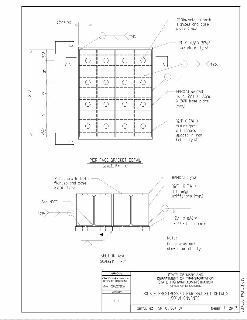
Cap plates not

2 3
DATE:
STATE HIGHWAY ADMINISTRATION
DEPARTMENT OF TRANSPORTATION
STATE OF MARYLAND
SHEET OF
APPROVAL
ST
RU
CT
UR
AL
RE
PA
IRS
OFFICE OF STRUCTURES
DIRECTOR
OFFICE OF STRUCTURES
1"T X 14 1/4 " X 15 1/4 "
cap plate (typ.)
Scale: 1" = 1’-0"
1.
2.
4 1/
2 "
4 1/
2 "
9"9"
3’-
0"
9"
2 3/
16 "
(ty
p.)
4 5
/8 "
(ty
p.)
(typ.)
1 3/4 "T X 15 1/4 "W
X 36"H base plate
HP14X73
plate (typ.)
5/8 "T X 7"W X full
spaced 1" from
holes (typ.)
SECTION B-B
3.
All steel shall be ASTM A709, GRADE 50.
For skewed members and/or substructure units,
height stiffners
2" Dia. hole in both
flanges and base
Notes:
Chamfer new plate as shown to clear fillet
so that edges of plate fit flush against
flange and web of HP Section.
refer to The Cap Supplement Detail.
SR-JS(PSB)-103
1.0
VERSION
DETAIL NO.
SINGLE PRESTRESSING BAR BRACKET DETAILS90 ALIGNMENTS
06/28/2017

3 3
DATE:
STATE HIGHWAY ADMINISTRATION
DEPARTMENT OF TRANSPORTATION
STATE OF MARYLAND
SHEET OF
APPROVAL
ST
RU
CT
UR
AL
RE
PA
IRS
OFFICE OF STRUCTURES
DIRECTOR
OFFICE OF STRUCTURES
SCALE: 1" = 1’-0"
AA
SECTION A-A
3 7/8 " (typ.)
BB
SECTION B-B
9"4
1/2
"9"
9"
3’-
0"
4 1/
2 "
ANCHOR PLATE DETAIL
2" Dia.
(typ.)
1 3/4 "T X 15 1/4 "W
X 36"H anchor
plate
2" Dia. hole
(typ.)
15 1/4 "
hole
1 3/4 "T X 15 1/4 "W
X 36"H anchor
plate
SR-JS(PSB)-103
1.0
VERSION
DETAIL NO.
SINGLE PRESTRESSING BAR BRACKET DETAILS90 ALIGNMENTS
06/28/2017
1 3
DATE:
STATE HIGHWAY ADMINISTRATION
DEPARTMENT OF TRANSPORTATION
STATE OF MARYLAND
SHEET OF
APPROVAL
ST
RU
CT
UR
AL
RE
PA
IRS
OFFICE OF STRUCTURES
DIRECTOR
OFFICE OF STRUCTURES
1"T X 14 1/4 " X 30 1/2 "
cap plate (typ.)
full height
spaced 1" from
holes (typ.)
PIER FACE BRACKET DETAIL
SCALE: 1" = 1’-0"
AA
1 3/4 "T X 15 1/4 "W
X 36"H base plate
See NOTE 1
SCALE: 1" = 1’-0"
SECTION A-A
3 7/8 " (Typ.)2" Dia. hole in both
plate (typ.)
plate (typ.) 5/8 "T X 7"W X
full height
stiffeners (typ.)
Note:
shown for clarity.
BB
3’-
0"
4 1/
2 "
9"9"
9"4
1/2
"
HP14X73 (typ.)
to A 1 3/4 "T X 15 1/4 "W
X 36"H base plate
(typ.)
typ.
flanges and base
typ.
HP14X73 welded
5/8 "T X 7"W X
stiffeners
2" Dia. hole in both
flanges and base
typ.
SR-JS(PSB)-104
1.0
VERSION
DETAIL NO.
DOUBLE PRESTRESSING BAR BRACKET DETAILS90 ALIGNMENTS
06/28/2017
Cap plates not

2 3
DATE:
STATE HIGHWAY ADMINISTRATION
DEPARTMENT OF TRANSPORTATION
STATE OF MARYLAND
SHEET OF
APPROVAL
ST
RU
CT
UR
AL
RE
PA
IRS
OFFICE OF STRUCTURES
DIRECTOR
OFFICE OF STRUCTURES
1"T X 14 1/4 " X 15 1/4 "
cap plate (typ.)
1.
2.
3.
For skewed members and/or substructure units,
SCALE: 1" = 1’-0"
4 1/
2 "
4 1/
2 "
9"9"
3’-
0"
9"
2 3/
16 "
(ty
p.)
4 5
/8 "
(ty
p.)
1 3/4 "T X 15 1/4 "W
X 36"H base plate
HP14X73
plate (typ.)
5/8 "T X 7"W X full
height stiffeners
spaced 1" from
holes (typ.)
SECTION B-B
typ.
2" Dia. hole in both
flanges and base
Notes:
Chamfer new plate as shown to clear fillet
so that edges of plate fit flush against
flange and web of HP Section.
All steel shall be ASTM A709, GRADE 50.
refer to the cap supplement detail.
SR-JS(PSB)-104
1.0
VERSION
DETAIL NO.
DOUBLE PRESTRESSING BAR BRACKET DETAILS90 ALIGNMENTS
06/28/2017

3 3
DATE:
STATE HIGHWAY ADMINISTRATION
DEPARTMENT OF TRANSPORTATION
STATE OF MARYLAND
SHEET OF
APPROVAL
ST
RU
CT
UR
AL
RE
PA
IRS
OFFICE OF STRUCTURES
DIRECTOR
OFFICE OF STRUCTURES
SCALE: 1" = 1’-0"
AA
SECTION A-A
BB
SECTION B-B
9"4
1/2
"9"
9"
3’-
0"
4 1/
2 "
ANCHOR PLATE DETAIL
2" Dia.
(typ.)
1 3/4 "T X 30 1/2 "W
X 36"H anchor
plate
2" Dia. hole
(typ.)
1 3/4 "T X
30 1/2 "W
X 36"H
plate
7 11/16 "7 9/16 "
(typ.)(typ.)
3 7/8 "
30 1/2 "
hole
anchor
SR-JS(PSB)-104
1.0
VERSION
DETAIL NO.
SINGLE PRESTRESSING BAR BRACKET DETAILS90 ALIGNMENTS
06/28/2017

1 2
DATE:
STATE HIGHWAY ADMINISTRATION
DEPARTMENT OF TRANSPORTATION
STATE OF MARYLAND
SHEET OF
APPROVAL
ST
RU
CT
UR
AL
RE
PA
IRS
OFFICE OF STRUCTURES
DIRECTOR
OFFICE OF STRUCTURES
plate (typ.)
HP14X73 Welded
to A 1 3/4 "T X 15 1/4 "W
X 36"H base plate
AA
HP14X73
SCALE: 1" = 1’-0"
SECTION A-A
BB
5/16
5/16
3"
1’-10 1/2 "
5"
SCALE: 1" = 1’-0"
CAP SUPPLEMENT DETAIL
ELEVATION
5/16
5/16 3" (typ.)
1/2 " Brace
plate (typ.)
5 1/
2 "
1’-8
7/8
"
1’-10 1/2 "
1"T cap plate for
skewed members
1/2 " Brace
typ.
typ.
1"T cap plate for
skewed members
SR-JS(PSB)-105
1.0
VERSION
DETAIL NO.
CAP PLATE FORSINGLE PRESTRESSING BAR BRACKETS
DETAILS SKEWED ALIGNMENTS
06/28/2017

2 2
DATE:
STATE HIGHWAY ADMINISTRATION
DEPARTMENT OF TRANSPORTATION
STATE OF MARYLAND
SHEET OF
APPROVAL
ST
RU
CT
UR
AL
RE
PA
IRS
OFFICE OF STRUCTURES
DIRECTOR
OFFICE OF STRUCTURES
SCALE: 1" = 1’-0"
SECTION B-B
5"
5 1/2 "HP14X73
1"T cap plate for
Place brace plate
to avoid cap plate
5/16
5/16
5/16
5/16
5/16
Tack
Existing
pier cap face
Note:
Jack support shall be placed
existing member being jacked.
10
" M
ax.
1’-8 7/8 "
skewed members
Girder
centerline
Jack support
along the same skew of the
SR-JS(PSB)-105
1.0
VERSION
DETAIL NO.
CAP PLATE FOR SINGLEPRESTRESSING BAR BRACKETSDETAILS SKEWED ALIGNMENTS
06/28/2017

1 2
DATE:
STATE HIGHWAY ADMINISTRATION
DEPARTMENT OF TRANSPORTATION
STATE OF MARYLAND
SHEET OF
APPROVAL
ST
RU
CT
UR
AL
RE
PA
IRS
OFFICE OF STRUCTURES
DIRECTOR
OFFICE OF STRUCTURES
1/2 " brace
plate (typ.)
1" brace plate
SCALE: 1" = 1’-0"
AA
SCALE: 1" = 1’-0"
SECTION A-A
BB
HP14X73 (typ.)
to A 1 3/4 "T X 15 1/4 "W
(typ.)
5"
CAP SUPPLEMENT DETAIL
ELEVATION
1"T cap plate for
5/16
5/16
5/16
5/16
5/16
5/16
5 1/
2 "
Brace plate
(typ.)
2 9/16 "
1’-8 7/8 "
1’-8 7/8 "
1’-8
7/8
"
1"T cap plate for
skewed members
typ.
Typ.
typ.
HP14X73 welded
X 36"H base plate
skewed members
typ.
SR-JS(PSB)-106
1.0
VERSION
DETAIL NO.
CAP PLATE FORDOUBLE PRESTRESSING BAR BRACKETS
DETAILS SKEWED ALIGNMENTS
06/28/2017

2 2
DATE:
STATE HIGHWAY ADMINISTRATION
DEPARTMENT OF TRANSPORTATION
STATE OF MARYLAND
SHEET OF
APPROVAL
ST
RU
CT
UR
AL
RE
PA
IRS
OFFICE OF STRUCTURES
DIRECTOR
OFFICE OF STRUCTURES
Jack support
SCALE: 1" = 1’-0"
SECTION B-B
5"
5 1/2 "
HP14X73
1"T cap plate for
Place brace plate
to avoid cap plate
(typ.) 5/16
5/16
5/16
Tack
Existing
pier cap face10
" M
ax.
SCALE: 1" = 1’-0"
MAX JACK SUPPORT OFFSET
Note:
existing member being jacked.
5/16
5/16
1’-8 7/8 "
skewed members
Girder
centerline
Jack support shall be placed
along the same skew of the
SR-JS(PSB)-106
1.0
VERSION
DETAIL NO.
CAP PLATE FORDOUBLE PRESTRESSING BAR BRACKETS
DETAILS SKEWED ALIGNMENTS
06/28/2017
DATE:
DIRECTOR
OFFICE OF STRUCTURES
SU
PP
OR
T
& S
PA
N
RE
CO
RD
ED
MA
XIM
UM
PR
ES
SU
RE
RE
AD
ING
(PS
I)
EN
G.
EN
G.
EN
G.
EN
G.
INS
PE
CT
OR
CA
LC
UL
AT
ED
MA
XIM
UM
FO
RC
E (
LB
S)
INS
PE
CT
OR
JA
CK
PIS
TO
N
DIA
ME
TE
R (
IN)
RE
CO
RD
ED
LIF
T
PR
ES
SU
RE
RE
AD
ING
(P
SI)
INS
PE
CT
OR
INS
PE
CT
OR
EX
PE
CT
ED
MIN
IMU
M
FO
RC
E (
LB
S)
EX
PE
CT
ED
MA
XIM
UM
FO
RC
E (
LB
S)
EN
G.
EN
G.
JAC
KS
ME
MB
ER
EN
G.
1 1
CA
LC
UL
AT
ED
MA
XIM
UM
FO
RC
E =
[
RE
CO
RD
ED
MA
XIM
UM
PR
ES
SU
RE
RE
AD
ING
] * [
0.7
85 *
JA
CK
PIS
TO
N D
IAM
ET
ER
]
SR-JS(PSB)-107
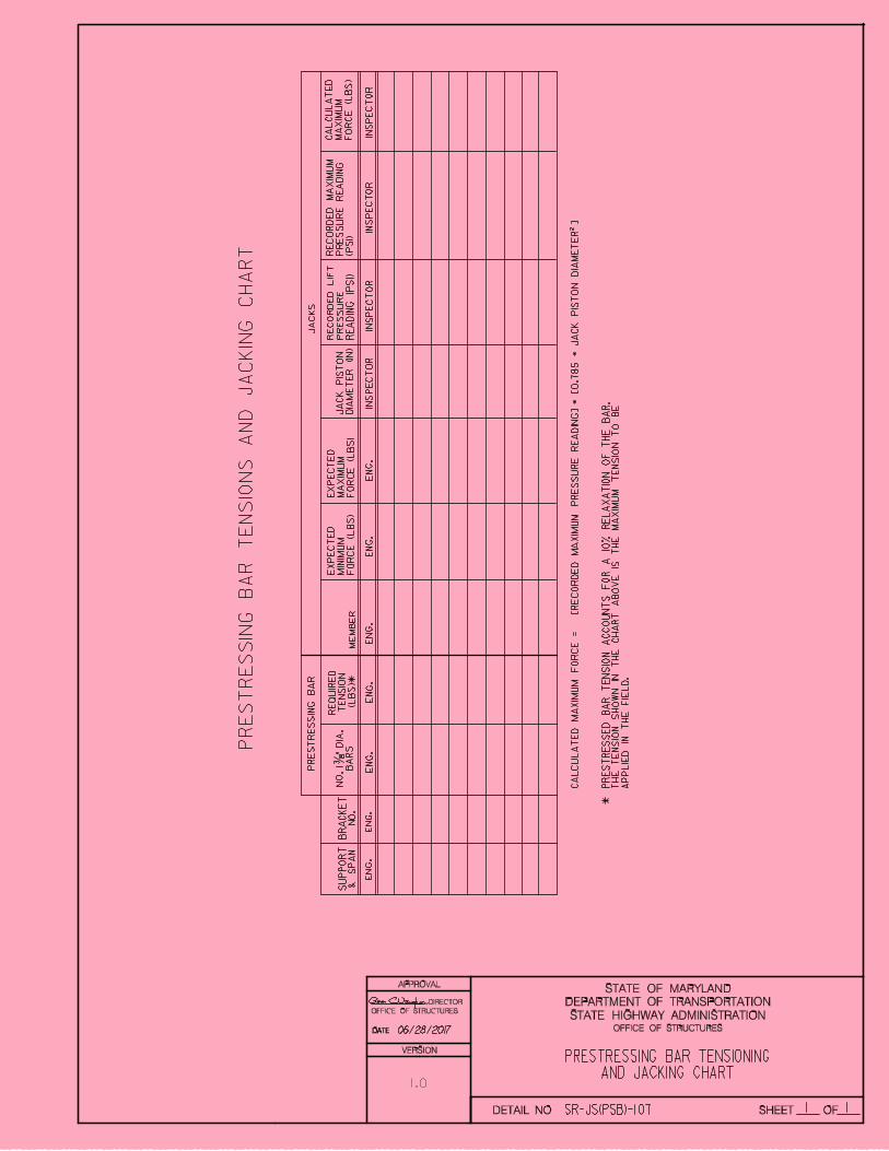
DATE:
STATE HIGHWAY ADMINISTRATION
DEPARTMENT OF TRANSPORTATION
STATE OF MARYLAND
SHEET OF
APPROVAL
OFFICE OF STRUCTURES
1.0
VERSION
DETAIL NO.
PRESTRESSING BAR TENSIONINGAND JACKING CHART
BR
AC
KE
T
NO
.
NO
. 1
3/8
" D
IA.
BA
RS
PR
ES
TR
ES
SIN
G B
AR
PR
ES
TR
ES
SIN
G B
AR
TE
NS
ION
S A
ND
JA
CK
ING
CH
AR
T
2
PR
ES
TR
ES
SE
D B
AR
TE
NS
ION
AC
CO
UN
TS
FO
R A
10
% R
EL
AX
AT
ION
OF
TH
E B
AR
.
TH
E T
EN
SIO
N S
HO
WN
IN
TH
E C
HA
RT
AB
OV
E I
S T
HE
MA
XIM
UM
TE
NS
ION
TO
BE
AP
PL
IED
IN
TH
E F
IEL
D.
*
*
RE
QU
IRE
D
TE
NS
ION
(LB
S)
06/28/2017

OFFICE OF STRUCTURES STRUCTURAL DETAIL MANUAL
Chapter 11 - Structural Repairs
Section 03 – Jacking Systems
SUB-SECTION 03
CHANNEL BRACKET
(SR-JS(CB))

1 1
FOR OFFICE USE ONLY
STATE HIGHWAY ADMINISTRATION
DEPARTMENT OF TRANSPORTATION
STATE OF MARYLAND
SHEET OF
ST
RU
CT
UR
AL
RE
PA
IRS
OFFICE OF STRUCTURES
DE
SIG
N G
UID
EL
INE
S F
OR
DO
UB
LE
CH
AN
NE
L J
AC
KIN
G B
RA
CK
ET
S
DOUBLE CHANNEL BRACKET DESIGN GUIDELINES
1)
2)
3)
4)
Th
e t
em
po
rary
jack
ing
sy
ste
m h
as b
een
desig
ned
at
op
erati
ng
str
ess l
ev
els
.
5)
Desig
ners s
ho
uld
att
em
pt
to m
inim
ize t
he n
um
ber o
f d
ifferen
t ja
ck
ing
sy
ste
ms
fo
r t
he b
rid
ge b
y d
esig
nin
g a
sy
ste
m t
hat
wil
l w
ork
in
mu
ltip
le l
ocati
on
s.
Bolt
s s
hall
be A
ST
M A
490 w
ith t
he t
hreads i
nclu
ded i
n t
he s
hear p
lane i
f
Only
the m
em
bers s
how
n b
elo
w a
re t
o b
e s
ele
cte
d f
or t
he j
ackin
g m
em
ber(s).
possib
le. T
he c
onnecti
on h
as b
een d
esig
ned a
s a
sli
p-crit
ical
connecti
on.
Mem
bers s
izes,
all
ow
ab
le l
oad
s,
max
imu
m l
ifti
ng
cap
acit
y,
an
d o
ff s
ets
sh
all
be
sh
ow
n i
n t
he s
tan
dard
s.
6)
Desig
ners s
hall
evalu
ate
the a
dja
cent
mem
ber f
or u
pli
ft.
If u
pli
ft
occurs, eit
her
eli
min
ate
up
lift
or a
cco
un
t fo
r u
pli
ft
by
jack
ing
th
e a
dja
cen
t m
em
ber o
r b
y o
ther
mean
s a
pp
rov
ed
by
th
e S
RE
D T
eam
Lead
er
an
d/o
r th
e S
RE
D D
ivis
ion
Ch
ief.
7)
Bra
ck
et
Mem
ber
2 -
C8x18.7
52
- C
10
x3
02
- C
12
x3
02
- C
15
x5
0
Off S
et
(ft)
Max
Jack
Lo
ad
(k
ips)
1.5
ft
2.5
ft
2ft
3ft
22
.00
16.0
0
NG
, D
efl
ecti
on
NG
, D
efl
ecti
on
34
.00
28
.00
NG
, D
efl
ecti
on
NG
, D
efl
ecti
on
49
.00
36
.00
NG
, D
efl
ecti
on
NG
, D
efl
ecti
on
NG
, D
efl
ecti
on
2 -
C8x18.7
52
- C
10
x3
02
- C
12
x3
02
- C
15
x5
0
44
.00
16.0
0
NG
, D
efl
ecti
on
NG
, D
efl
ecti
on
68
.00
28
.00
NG
, D
efl
ecti
on
NG
, D
efl
ecti
on
98
.00
36
.00
NG
, D
efl
ecti
on
NG
, D
efl
ecti
on
NG
, D
efl
ecti
on
10
0.0
0
12
0.0
0
Fil
let
Weld
Sti
ffen
er
Wid
th
Tota
l N
o.
Bo
lts-
Ex
isti
ng
Web
Tota
l N
o.
Bo
lts-
Ex
isti
ng
Sti
ffen
er
7/16
’’ 5/
8 ’’
7/16
’’ 5/
8 ’’
7/16
’’ 5/
8 ’’
7/16
’’ 5/
8 ’’
2’’
2 3/
8 ’’
2 5/
8 ’’
3’’
2’’
2 3/
8 ’’
2 5/
8 ’’
3’’
4/C
onn. P
late
=8
4/C
onn. P
late
=8
6/C
on
n.
Pla
te=1
28/C
onn. P
late
=16
4/C
onn. P
late
=8
4/C
onn. P
late
=8
6/C
on
n.
Pla
te=1
28/C
onn. P
late
=16
2/S
tiffener
=4
2/S
tiffener
=4
3/S
tiffener
=6
4/S
tiffener
=8
2/S
tiffener
=4
2/S
tiffener
=4
3/S
tiffener
=6
4/S
tiffener
=8
On
ce j
ack
ing
rep
air
s a
re c
om
ple
te,
insta
ll b
eam
en
d r
etr
ofit
pla
tes a
s p
er t
he B
earin
g
Sti
ffener
Pla
ting D
eta
il (
SR
-ST
-30X
) or
the G
irder
End P
lati
ng D
eta
il (
SR
-ST
-40X
or
SR
-ST
-50X
).
50.0
0
42
.00
85
.00
SR-JS(CB)-101
60.0
0
DETAIL NO.
DATE:
APPROVAL
DIRECTOR
OFFICE OF STRUCTURES
VERSION
1.0
Max C
om
bin
ed L
ifti
ng C
apacit
y (
kip
s)
06/28/2017
* GUIDE SHEET FOR PLAN DEVELOPMENT ONLY - DO NOT INCLUDE THIS SHEET IN CONTRACT PLANS *

Existing diaphragm
See jack support
assembly detail
Jack, stiffener, jack
support assembly, etc.
Jack Offset
2
Scale : None
(Typ.)
Maximum Jack Force
Jack Offset
Location:Size:
2
Existingstiffener(typ.)
JACKING MEMBER TABLE
5/16 "
5/16 "
1 5
STATE HIGHWAY ADMINISTRATION
DEPARTMENT OF TRANSPORTATION
STATE OF MARYLAND
SHEET OF
ST
RU
CT
UR
AL
RE
PA
IRS
OFFICE OF STRUCTURES
CHANNEL BRACKET JACKING DETAILS
Double C-Channel Jacking member(set level)
Double C-Channel Jacking Member
Proposed 5/8 ’’stiffener(typ.)
Proposed full height xL x 1 1/2 ’’ thick fillplate (typ.)
(Typ.)
(Typ.)
Proposed fillplate (typ.)
Existing interior/exterior beam
(beam to be raised)
L
See typical
connection
detail on Sheet 2
CHANNEL BRACKET JACKING MEMBER
Required Jack Capacity
L , Length of fill plate at ext. stiffener
L , Length of fill plate along bracket
Proposed Bracket Stiffener Plate Size
L2
1
2
1
Notes:
1. Only A709 Grade 50 steel shall be used.
2. Jacking members do not have to be new, but shall be in good condition.
3. The jack shall not be used to support load during bearing repairs.
4. Jacking members shall be placed level unless otherwise noted.
5. The Contractor has the option of submitting another method of jacking to
the Engineer for approval. The design shall be done by a PE registered in Md.
6. Jacking member shall be kept low to minimize height of stacked plates or the
HP column jack support.
7. Anchor bolt nuts may need to be loosened at the exterior and adjacent
interior beams to allow the beam to rise.
8. Beams shall not be raised more than 1/8 ’’ above its existing elevation.
9. Proposed stiffener plates shall be fabricated to bear directly on and
match the slope of the flanges of the proposed channel sections.
10. Chipping of the existing concrete is not required for the jack stand leveling
pad unless approved by the engineer.
11. The entire procedure (jacking, debris removal, shim installation, lowering,
and bracket removal) shall completed in a timely manner as approved by the Engineer.
12. Once jacking repairs are complete, install beam end retrofit plates as the Bearing
Stiffener Plating Standard or the Girder End Plating Standards as attached. Retrofit bolt
spacing shall incorporate all bolt holes used for jacking.
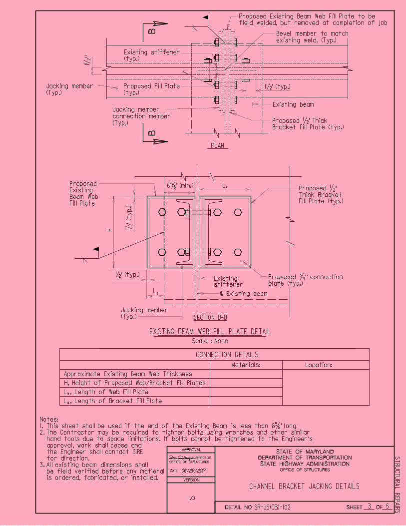
SR-JS(CB)-102DETAIL NO.
DATE:
APPROVAL
DIRECTOR
OFFICE OF STRUCTURES
VERSION
1.0
06/28/2017

PLAN
2
Scale : None
TYPICAL 90^ CONNECTION DETAIL
Jacking member
(Typ.)
Jacking member
(Typ.)
CONNECTION DETAILS
Location:Materials:
Connection Bolts
2 5
STATE HIGHWAY ADMINISTRATION
DEPARTMENT OF TRANSPORTATION
STATE OF MARYLAND
SHEET OF
ST
RU
CT
UR
AL
RE
PA
IRS
OFFICE OF STRUCTURES
CHANNEL BRACKET JACKING DETAILS
1 1/2
’’
Existing beam
Existing beam
1 1/2 ’’
Equal
Space(s
)
1 1/2 ’’ (typ.)
Jacking member
connection member
(Typ.)
AA
3’’ (typ.)
6’’
max
(typ.)
Existing stiffener
SECTION A-A
b
Proposed 3/4 ’’ connection
plate (typ.)
Double C-Channel Jacking Member
3’’
min
6 5/8 ’’ (typ.)
Fu
ll H
eig
ht
+ 1
1/4
’’
W
5/8 ’’ (typ.)
W - Connection plate weld size
1 1/2 " (typ.)
1" (typ.)
7" Max.
Existing stiffener
(typ.)
Proposed Fill Plate
(typ.)
No. Bracket Connection Bolt Rows
b - No. Connection Bolts in existing stiffener
b - No. Bracket Connection Plate Bolts
A490, 7/8 " dia.
_ per side = _ total
_ per side = _ total
* *
b2
1
2
1
Length will vary and requires
field verification. If the
bracket connection plate
overhangs the end of the
existing beam, fill plates
shall be installed to establish
bearing. Refer to Sheet 3
for details.
Bevel member to match
existing weld. (Typ.)
Notes:
1. Minimum height of connection plate: 9 1/4 ’’ for C8x18.75; 11 1/4 ’’ for C10x30; 13 1/4 ’’ for C12x30; & 16 1/4 ’’ for C15x50.
2. b - Number of 7/8 ’’ dia. A490 Bolts required on each bracket connection plate and existing stiffener.
3. W - Connection plate weld size, E70 electrodes.
4. The gap between the channel webs
shall be located at the span side of
the stiffener.
5. Jacking members shall be placed as
close as possible to the
end diaphragm.
6. New bolts to be reinstalled in bolt
holes after jacking unless otherwise
stated in the plans.
SR-JS(CB)-102DETAIL NO.
DATE:
APPROVAL
DIRECTOR
OFFICE OF STRUCTURES
VERSION
1.0
06/28/2017
3 5
STATE HIGHWAY ADMINISTRATION
DEPARTMENT OF TRANSPORTATION
STATE OF MARYLAND
SHEET OF
ST
RU
CT
UR
AL
RE
PA
IRS
OFFICE OF STRUCTURES
CHANNEL BRACKET JACKING DETAILS
2
Scale : None
Jacking member
(Typ.)
Existing beam
Proposed 3/4 ’’ connection
plate (typ.)
CONNECTION DETAILS
Location:Materials:
3
1/2 " (typ.)
6 5/8 " (min.)
H
L , Length of Web Fill Plate
Approximate Existing Beam Web Thickness
EXISTING BEAM WEB FILL PLATE DETAIL
Existing stiffener
L3
L4
4L , Length of Bracket Fill Plate
1/2
" (
typ
.)
Proposed
Existing
Beam Web
Fill Plate
SECTION B-B
PLAN
Jacking member
(Typ.)
1 1/2
’’
Existing beamJacking member
connection member
(Typ.)
BB
1 1/2 " (typ.)
Existing stiffener
(typ.)
Proposed Fill Plate
(typ.)
Proposed 1/2 " Thick
Bracket Fill Plate (typ.)
Proposed 1/2 "
Thick Bracket
Fill Plate (typ.)
Bevel member to match
existing weld. (Typ.)
H, Height of Proposed Web/Bracket Fill Plates
Notes:
1. This sheet shall be used if the end of the Existing Beam is less than 6 5/8 " long.
2. The Contractor may be required to tighten bolts using wrenches and other similar
hand tools due to space limitations. If bolts cannot be tightened to the Engineer’s
approval, work shall cease and
the Engineer shall contact SIRE
for direction.
3. All existing beam dimensions shall
be field verified before any matieral
is ordered, fabricated, or installed.
SR-JS(CB)-102DETAIL NO.
Proposed Existing Beam Web Fill Plate to be
field welded, but removed at completion of job
DATE:
APPROVAL
DIRECTOR
OFFICE OF STRUCTURES
VERSION
1.0
06/28/2017

2
Top of jacking surface
BB
2
Top of jacking surface
Nonshrink grout
leveling pad
(as required)
Nonshrink grout
leveling pad
(as required)
Scale : None
Scale : None
Typ.
ELEVATION
JACK SUPPORT USING STACKED PLATES
Tack
Typ.
1’’ x 12’’ x 1’-0’’
See jack support assembly detail
Stacked plates height
as required (12’’ max.)
1/2 ’’ x 12’’ x 1’-0’’ plates
(or thicker).
ELEVATION
ALTERNATE COLUMN SPACER DETAIL
5/16
bearing plate
1’’ x 12’’ x 1’-0’’ base plate
HP8 x 36 column spacer
1’’ x 12’’ x 1’-0’’
masonry plate
Tack weld shim plate as
needed in field, see detail
Jacking member
Jack, plates, and
jack support assembly
1’’ x 12’’ x 1’-0’’ base plate
of jack support assembly
Jack, plates and jack
support assembly
4 5
STATE HIGHWAY ADMINISTRATION
DEPARTMENT OF TRANSPORTATION
STATE OF MARYLAND
SHEET OF
ST
RU
CT
UR
AL
RE
PA
IRS
OFFICE OF STRUCTURES
CHANNEL BRACKET JACKING DETAILS
5/16
Proposed 5/8 ’’stiffener(typ.)
5/16
Proposed full height x L x 1 1/2 ’’ thick fill plate (typ.)
Existing beambearing stiffener
1"
Notes:
1. Minimum thickness of the grout leveling pad
shall be as recommended by manufacturer.
2. Jack shall be centered under jacking
beam web and stiffeners.
3. Stacked plates shall not exceed 12’’
high.
4. HP8 x 36 column spacer shall not
exceed 5’-0’’ high.
5. All material for the Jack Support
and Column Spacer to be ASTM
A 709 Grade 50. Grade 36 is also
acceptable with the approval of
the Engineer.
SR-JS(CB)-102DETAIL NO.
DATE:
APPROVAL
DIRECTOR
OFFICE OF STRUCTURES
VERSION
1.0
06/28/2017

2
Jack
Jack, plates
and channels
3’’3’’
6’’
6’’
Scale : None
SHIM PLATE DETAIL
1/2 ’’ x 1’-0’’ Plate
Scale : None
SECTION B-B
Typ.
Jack piston radius plus 1/4 ’’
12’’
12’’
Note:
This plate is not welded to
the jack support assembly.
Note:
The length of the channels and
the 1/2 ’’ plate are to be custom
fit to the jack being used.
5/16
5/16
C9 x 15 (Typ.)
1’’ x 12’’ x 1’-0’’
Base plate
Typ. 5/16
2 Shim plate
1/4 ’’ (min.) x 12’’ x 1’-0’’ Plate
Jack piston diameter plus 1/2 ’’
Equal spacer
5 5
STATE HIGHWAY ADMINISTRATION
DEPARTMENT OF TRANSPORTATION
STATE OF MARYLAND
SHEET OF
ST
RU
CT
UR
AL
RE
PA
IRS
OFFICE OF STRUCTURES
CHANNEL BRACKET JACKING DETAILS
SR-JS(CB)-102DETAIL NO.
DATE:
APPROVAL
DIRECTOR
OFFICE OF STRUCTURES
VERSION
1.0
06/28/2017

EXPECTED
MINIMUM
FORCE (LBS)
EXPECTED
MAXIMUM
FORCE (LBS)
RECORDED LIFT
PRESSURE
READING (PSI)MEMBER
SUPPORT
& SPAN
JACK PISTON
DIAMETER (IN)
RECORDED MAXIMUM
PRESSURE READING
(PSI)
ENG. ENG. ENG. ENG. INSPECTOR INSPECTOR INSPECTOR
CALCULATED
MAXIMUM
FORCE (LBS)
INSPECTOR
JACKING CHART
1 1
DOUBLE CHANNEL BRACKETJACKING CHART
SR-JS(CB)-103
STATE HIGHWAY ADMINISTRATION
DEPARTMENT OF TRANSPORTATION
STATE OF MARYLAND
SHEET OF
OFFICE OF STRUCTURES
DETAIL NO.
DATE:
APPROVAL
DIRECTOR
OFFICE OF STRUCTURES
VERSION
1.0
2
CALCULATED MAXIMUM FORCE = [ RECORDED MAXIMUM PRESSURE READING ] * [ 0.785 * JACK PISTON DIAMETER ]
06/28/2017