Embed Size (px)
Citation preview
9/8/98 AC 43.13-1B
Par 11-1 Page 11-1
CHAPTER 11. AIRCRAFT ELECTRICAL SYSTEMS
SECTION 1. INSPECTION AND CARE OF ELECTRICAL SYSTEMS
11-1. GENERAL. The term “electricalsystem” as used in this AC means those partsof the aircraft that generate, distribute, and useelectrical energy, including their support andattachments. The satisfactory performance ofan aircraft is dependent upon the continued re-liability of the electrical system. Damagedwiring or equipment in an aircraft, regardlessof how minor it may appear to be, cannot betolerated. Reliability of the system is propor-tional to the amount of maintenance receivedand the knowledge of those who perform suchmaintenance. It is, therefore, important thatmaintenance be accomplished using the besttechniques and practices to minimize the pos-sibility of failure. This chapter is not intendedto supersede or replace any government speci-fication or specific manufacturer’s instructionregarding electrical system inspection and re-pair.
11-2. INSPECTION AND OPERATIONCHECKS. Inspect equipment, electrical as-semblies, and wiring installations for damage,general condition, and proper functioning toensure the continued satisfactory operation ofthe electrical system. Adjust, repair, overhaul,and test electrical equipment and systems inaccordance with the recommendations andprocedures in the aircraft and/or componentmanufacturer’s maintenance instructions. Re-place components of the electrical system thatare damaged or defective with identical parts,with aircraft manufacturer’s approved equip-ment, or its equivalent to the original in oper-ating characteristics, mechanical strength, andenvironmental specifications. A list of sug-gested problems to look for and checks (Referto the glossary for a description of the checktypes) to be performed are:
a. Damaged, discolored, or overheatedequipment, connections, wiring, and installa-tions.
b. Excessive heat or discoloration at highcurrent carrying connections.
c. Misalignment of electrically drivenequipment.
d. Poor electrical bonding (broken, dis-connected or corroded bonding strap) andgrounding, including evidence of corrosion.
e. Dirty equipment and connections.
f. Improper, broken, inadequately sup-ported wiring and conduit, loose connectionsof terminals, and loose ferrules.
g. Poor mechanical or cold solder joints.
h. Condition of circuit breaker andfuses.
i. Insufficient clearance between exposedcurrent carrying parts and ground or poor in-sulation of exposed terminals.
j. Broken or missing safety wire, brokenbundle lacing, cotter pins, etc.
k. Operational check of electrically oper-ated equipment such as motors, inverters, gen-erators, batteries, lights, protective devices,etc.
l. Ensure that ventilation and cooling airpassages are clear and unobstructed.

AC 43.13-1B 9/8/98
Page 11-2 Par 11-2
m. Voltage check of electrical systemwith portable precision voltmeter.
n. Condition of electric lamps.
o. Missing safety shields on exposedhigh-voltage terminals (i.e., 115/200V ac).
11-3. FUNCTIONAL CHECK OFSTAND-BY OR EMERGENCY EQUIP-MENT. An aircraft should have functionaltests performed at regular intervals as pre-scribed by the manufacturer. The inspectionsor functional check periods should be clearlystated in the aircraft maintenance manual,along with the overhaul intervals.
11-4. CLEANING AND PRESERVA-TION. Annual cleaning of electrical equip-ment to remove dust, dirt, and grime is rec-ommended. Suitable solvents or fine abrasivesthat will not score the surface or remove theplating may be used to clean the terminals andmating surfaces if they are corroded or dirty.Only cleaning agents that do not leave any typeof residue must be used. Components must becleaned and preserved in accordance with theaircraft handbooks or manufacturer’s instruc-tions. Avoid using emery cloth to polishcommutators or slip rings because particlesmay cause shorting and burning. Be sure thatprotective finishes are not scored or damagedwhen cleaning. Ensure that metal-to-metalelectrically bonded surfaces are treated at theinterface with a suitable anti-corrosive con-ductive coating, and that the joint is sealedaround the edges by restoring the originalprimer and paint finish. Connections that mustwithstand a highly corrosive environment maybe encapsulated with an approved sealant inorder to prevent corrosion.
CAUTION: Turn power off beforecleaning.
11-5. BATTERY ELECTROLYTE COR-ROSION. Corrosion found on or near lead-acid batteries can be removed mechanicallywith a stiff bristle brush and then chemicallyneutralized with a 10 percent sodium bicar-bonate and water solution. For Nickel Cad-mium (NiCad) batteries, a 3 percent solutionof acetic acid can be used to neutralize theelectrolyte. After neutralizing, the batteryshould be washed with clean water and thor-oughly dried.
11-6. ADJUSTMENT AND REPAIR. Ac-complish adjustments to items of equipmentsuch as regulators, alternators, generators,contactors, control devices, inverters, and re-lays at a location outside the aircraft, and on atest stand or test bench where all necessary in-struments and test equipment are at hand.Follow the adjustment and repair proceduresoutlined by the equipment or aircraft manu-facturer. Replacement or repair must be ac-complished as a part of routine maintenance.Adjustment of a replacement voltage regulatoris likely since there will always be a differencein impedance between the manufacturer’s testequipment and the aircraft’s electrical system.
11-7. INSULATION OF ELECTRICALEQUIPMENT. In some cases, electricalequipment is connected into a heavy currentcircuit, perhaps as a control device or relay.Such equipment is normally insulated from themounting structure since grounding the frameof the equipment may result in a seriousground fault in the event of equipment internalfailure. Stranded 18 or 20 AWG wire shouldbe used as a grounding strap to avoid shockhazard to equipment and personnel. If the endconnection is used for shock hazard, theground wire must be large enough to carry thehighest possible current (0.1 to 0.2 ohmsmax.).
9/8/98 AC 43.13-1B
Par 11-8 Page 11-3 (and 11-4)
11-8. BUS BARS. Annually check bus barsfor general condition, cleanliness, and securityof all attachments and terminals. Grease, cor-rosion, or dirt on any electrical junction maycause the connections to overheat and eventu-ally fail. Bus bars that exhibit corrosion, evenin limited amounts, should be disassembled,cleaned and brightened, and reinstalled.
11-9. 11-14. [RESERVED.]

9/8/98 AC 43.13-1B
Par 11-15 Page 11-5
SECTION 2. STORAGE BATTERIES
11-15. GENERAL. Aircraft batteries maybe used for many functions, e.g., groundpower, emergency power, improving DC busstability, and fault-clearing. Most small pri-vate aircraft use lead-acid batteries. Mostcommercial and military aircraft use NiCadbatteries. However, other types are becomingavailable such as gel cell and sealed lead-acidbatteries. The battery best suited for a par-ticular application will depend on the relativeimportance of several characteristics, such asweight, cost, volume, service or shelf life, dis-charge rate, maintenance, and charging rate.Any change of battery type may be considereda major alteration.
a. Storage batteries are usually identifiedby the material used for the plates. All batterytypes possess different characteristics and,therefore, must be maintained in accordancewith the manufacturer’s recommendations..
WARNING: It is extremely danger-ous to store or service lead-acid andNiCad batteries in the same area. In-troduction of acid electrolytes into al-kaline electrolyte will destroy the Ni-Cad and vice-versa.
11-16. BATTERY CHARGING. Operationof storage batteries beyond their ambient tem-perature or charging voltage limits can result inexcessive cell temperatures leading to electro-lyte boiling, rapid deterioration of the cells,and battery failure. The relationship betweenmaximum charging voltage and the number ofcells in the battery is also significant. This willdetermine (for a given ambient temperatureand state of charge) the rate at which energy isabsorbed as heat within the battery. For lead-acid batteries, the voltage per cell must not ex-ceed 2.35 volts. In the case of NiCad batteries,the charging voltage limit varies with designand construction. Values of
1.4 and 1.5 volts per cell are generally used. Inall cases, follow the recommendations of thebattery manufacturer.
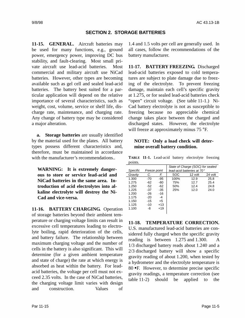
11-17. BATTERY FREEZING. Dischargedlead-acid batteries exposed to cold tempera-tures are subject to plate damage due to freez-ing of the electrolyte. To prevent freezingdamage, maintain each cell’s specific gravityat 1.275, or for sealed lead-acid batteries check“open” circuit voltage. (See table 11-1.) Ni-Cad battery electrolyte is not as susceptible tofreezing because no appreciable chemicalchange takes place between the charged anddischarged states. However, the electrolytewill freeze at approximately minus 75 °F.
NOTE: Only a load check will deter-mine overall battery condition.
TABLE 11-1. Lead-acid battery electrolyte freezingpoints.
Specific Freeze pointState of Charge (SOC) for sealedlead-acid batteries at 70°
Gravity C. F. SOC 12 volt 24 volt1.300 -70 -95 100% 12.9 25.81.275 -62 -80 75% 12.7 25.41.250 -52 -62 50% 12.4 24.81.225 -37 -35 25% 12.0 24.01.200 -26 -161.175 -20 -41.150 -15 +51.125 -10 +131.100 -8 +19
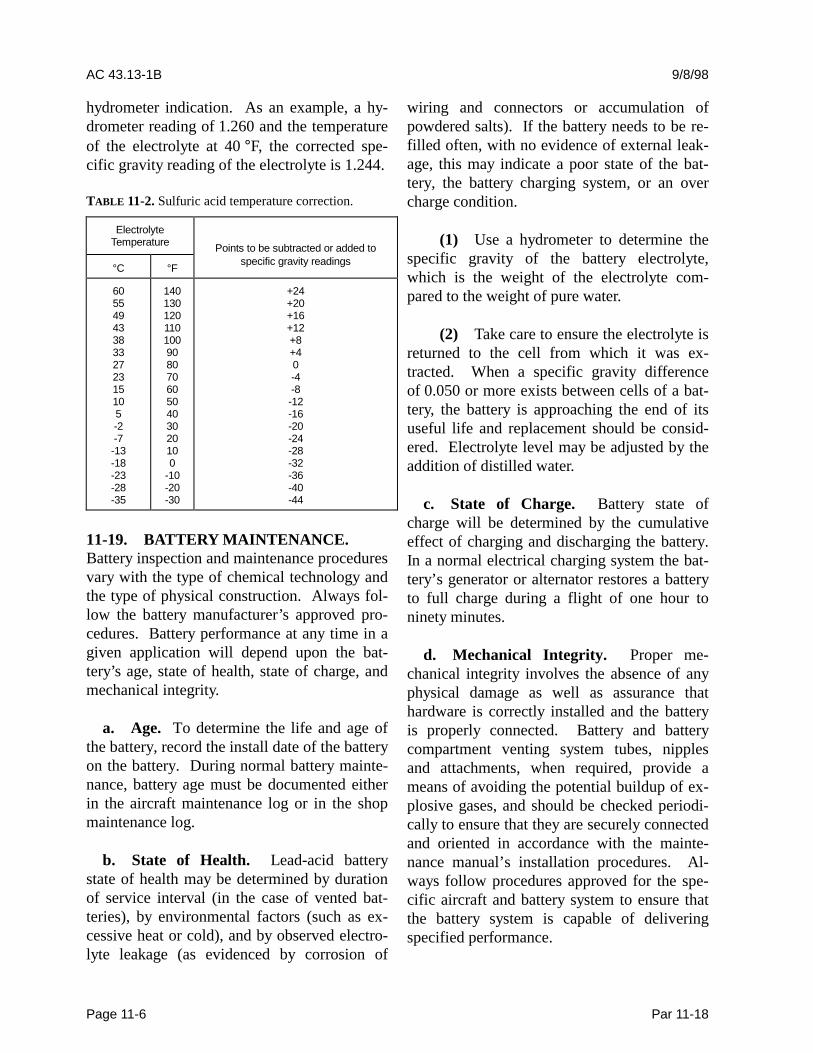
11-18. TEMPERATURE CORRECTION.U.S. manufactured lead-acid batteries are con-sidered fully charged when the specific gravityreading is between 1.275 and 1.300. A1/3 discharged battery reads about 1.240 and a2/3 discharged battery will show a specificgravity reading of about 1.200, when tested bya hydrometer and the electrolyte temperature is80 �F. However, to determine precise specificgravity readings, a temperature correction (seetable 11-2) should be applied to the
AC 43.13-1B 9/8/98
Page 11-6 Par 11-18
hydrometer indication. As an example, a hy-drometer reading of 1.260 and the temperatureof the electrolyte at 40 °F, the corrected spe-cific gravity reading of the electrolyte is 1.244.
TABLE 11-2. Sulfuric acid temperature correction.
ElectrolyteTemperature Points to be subtracted or added to
°C °F specific gravity readings
605549433833272315105-2-7-13-18-23-28-35
1401301201101009080706050403020100
-10-20-30
+24+20+16+12+8+40-4-8-12-16-20-24-28-32-36-40-44
11-19. BATTERY MAINTENANCE.Battery inspection and maintenance proceduresvary with the type of chemical technology andthe type of physical construction. Always fol-low the battery manufacturer’s approved pro-cedures. Battery performance at any time in agiven application will depend upon the bat-tery’s age, state of health, state of charge, andmechanical integrity.
a. Age. To determine the life and age ofthe battery, record the install date of the batteryon the battery. During normal battery mainte-nance, battery age must be documented eitherin the aircraft maintenance log or in the shopmaintenance log.
b. State of Health. Lead-acid batterystate of health may be determined by durationof service interval (in the case of vented bat-teries), by environmental factors (such as ex-cessive heat or cold), and by observed electro-lyte leakage (as evidenced by corrosion of
wiring and connectors or accumulation ofpowdered salts). If the battery needs to be re-filled often, with no evidence of external leak-age, this may indicate a poor state of the bat-tery, the battery charging system, or an overcharge condition.
(1) Use a hydrometer to determine thespecific gravity of the battery electrolyte,which is the weight of the electrolyte com-pared to the weight of pure water.
(2) Take care to ensure the electrolyte isreturned to the cell from which it was ex-tracted. When a specific gravity differenceof 0.050 or more exists between cells of a bat-tery, the battery is approaching the end of itsuseful life and replacement should be consid-ered. Electrolyte level may be adjusted by theaddition of distilled water.
c. State of Charge. Battery state ofcharge will be determined by the cumulativeeffect of charging and discharging the battery.In a normal electrical charging system the bat-tery’s generator or alternator restores a batteryto full charge during a flight of one hour toninety minutes.
d. Mechanical Integrity. Proper me-chanical integrity involves the absence of anyphysical damage as well as assurance thathardware is correctly installed and the batteryis properly connected. Battery and batterycompartment venting system tubes, nipplesand attachments, when required, provide ameans of avoiding the potential buildup of ex-plosive gases, and should be checked periodi-cally to ensure that they are securely connectedand oriented in accordance with the mainte-nance manual’s installation procedures. Al-ways follow procedures approved for the spe-cific aircraft and battery system to ensure thatthe battery system is capable of deliveringspecified performance.
9/8/98 AC 43.13-1B
Par 11-19 Page 11-7
e. Battery and Charger Characteristics.The following information is provided to ac-quaint the user with characteristics of the morecommon aircraft battery and battery chargertypes. Products may vary from these descrip-tions due to different applications of availabletechnology. Consult the manufacturer for spe-cific performance data.
NOTE: Under no circumstances con-nect a lead-acid battery to a charger,unless properly serviced.
(1) Lead-acid vented batteries have atwo volt nominal cell voltage. Batteries areconstructed so that individual cells cannot beremoved. Occasional addition of water is re-quired to replace water loss due to overcharg-ing in normal service. Batteries that becomefully discharged may not accept recharge.
(2) Lead-acid sealed batteries are simi-lar in most respects to lead-acid vented batter-ies, but do not require the addition of water.
(3) The lead-acid battery is economicaland has extensive application, but is heavierthan an equivalent performance battery of an-other type. The battery is capable of a highrate of discharge and low temperature per-formance. However, maintaining a high rateof discharge for a period of time usually warpsthe cell plates, shorting out the battery. Itselectrolyte has a moderate specific gravity, andstate of charge can be checked with a hy-drometer.
(4) Do not use high amperage automo-tive battery chargers to charge aircraftbatteries.
(5) NiCad vented batteries have a1.2 volt nominal cell voltage. Occasional ad-dition of distilled water is required to replacewater loss due to overcharging in normalservice. Cause of failure is usually shorting or
weakening of a cell. After replacing the badcell with a good cell, the battery’s life can beextended for five or more years. Full dis-charge is not harmful to this type of battery.
(6) NiCad sealed batteries are similar inmost respects to NiCad vented batteries, but donot normally require the addition of water.Fully discharging the battery (to zero volts)may cause irreversible damage to one or morecells, leading to eventual battery failure due tolow capacity.
(7) The state of charge of a NiCad bat-tery cannot be determined by measuring thespecific gravity of the potassium hydroxideelectrolyte. The electrolyte specific gravitydoes not change with the state of charge. Theonly accurate way to determine the state ofcharge of a NiCad battery is by a measureddischarge with a NiCad battery charger andfollowing the manufacturer’s instructions.After the battery has been fully charged andallowed to stand for at least two hours, thefluid level may be adjusted, if necessary, usingdistilled or demineralized water. Because thefluid level varies with the state of charge, wa-ter should never be added while the battery isinstalled in the aircraft. Overfilling the batterywill result in electrolyte spewage duringcharging. This will cause corrosive effects onthe cell links, self-discharge of the battery, di-lution of the electrolyte density, possibleblockage of the cell vents, and eventual cellrupture.
(8) Lead-acid batteries are usuallycharged by regulated DC voltage sources. Thisallows maximum accumulation of charge inthe early part of recharging.
(9) Constant-current battery chargersare usually provided for NiCad batteries be-cause the NiCad cell voltage has a negativetemperature coefficient. With a constant-voltage charging source, a NiCad battery
AC 43.13-1B 9/8/98
Page 11-8 Par 11-19
having a shorted cell might overheat due to ex-cessive overcharge and undergo a thermal run-away, destroying the battery and creating apossible safety hazard to the aircraft.
DEFINITION: Thermal runaway canresult in a chemical fire and/or explo-sion of the NiCad battery under re-charge by a constant-voltage source,and is due to cyclical, ever-increasingtemperature and charging current.One or more shorted cells or an exist-ing high temperature and low chargecan produce the cyclical sequence ofevents: (1) excessive current,(2) increased temperature,(3) decreased cell(s) resistance,(4) further increased current, and(5) further increased temperature.This will not become a self-sustainingthermal-chemical action if the con-stant-voltage charging source is re-moved before the battery temperatureis in excess of 160 °°°°F.
(10) Pulsed-current battery chargers aresometimes provided for NiCad batteries.
CAUTION: It is important to use theproper charging procedures for bat-teries under test and maintenance.These charging regimes for recondi-tioning and charging cycles are de-fined by the aircraft manufacturerand should be closely followed.
f. Shop-Level Maintenance Procedures.Shop procedures must follow the manufac-turer’s recommendations. Careful examinationof sealed batteries and proper reconditioning ofvented batteries will ensure the longest possi-ble service life.
g. Aircraft Battery Inspection.
(1) Inspect battery sump jar and linesfor condition and security.
(2) Inspect battery terminals and quick-disconnect plugs and pins for evidence of cor-rosion, pitting, arcing, and burns. Clean as re-quired.
(3) Inspect battery drain and vent linesfor restriction, deterioration, and security.
(4) Routine pre-flight and post-flightinspection procedures should include observa-tion for evidence of physical damage, looseconnections, and electrolyte loss.
11-20. ELECTROLYTE SPILLAGE.Spillage or leakage of electrolyte may result inserious corrosion of the nearby structure orcontrol elements as both sulfuric acid and po-tassium hydroxide are actively corrosive.Electrolyte may be spilled during groundservicing, leaked when cell case rupture oc-curs, or sprayed from cell vents due to exces-sive charging rates. If the battery is not caseenclosed, properly treat structural parts nearthe battery that may be affected by acid fumes.Treat all case and drain surfaces, that havebeen affected by electrolyte, with a solution ofsodium bicarbonate (for acid electrolyte) orboric acid, vinegar, or a 3 percent solution ofacetic acid (for potassium hydroxideelectrolyte).
CAUTION: Serious burns will resultif the electrolyte comes in contact withany part of the body. Use rubbergloves, rubber apron, and protectivegoggles when handling electrolyte. Ifsulfuric acid is splashed on the body,
9/8/98 AC 43.13-1B
Par 11-20 Page 11-9
neutralize with a solution of bakingsoda and water, and shower or flushthe affected area with water. For theeyes, use an eye fountain and flushwith an abundance of water. If potas-sium hydroxide contacts the skin, neu-tralize with 9 percent acetic acid,vinegar, or lemon juice and wash withwater. For the eyes, wash with a weaksolution of boric acid or a weak solu-tion of vinegar and flush with water.
11-21. NOXIOUS FUMES. When chargingrates are excessive, the electrolyte may boil tothe extent that fumes containing droplets of theelectrolyte are emitted through the cell vents.These fumes from lead-acid batteries may be-come noxious to the crew members and pas-sengers; therefore, thoroughly check the vent-ing system. NiCad batteries will emit gas nearthe end of the charging process and duringovercharge. The battery vent system in the air-craft should have sufficient air flow to preventthis explosive mixture from accumulating. Itis often advantageous to install a jar in thebattery vent discharge system serviced with anagent to neutralize the corrosive effect of bat-tery vapors.
11-22. INSTALLATION PRACTICES.
a. External Surface. Clean the externalsurface of the battery prior to installation in theaircraft.
b. Replacing Lead-Acid Batteries.When replacing lead-acid batteries with NiCadbatteries, a battery temperature or currentmonitoring system must be installed. Neu-tralize the battery box or compartment andthoroughly flush with water and dry. A flightmanual supplement must also be provided forthe NiCad battery installation. Acid residuecan be detrimental to the proper functioning ofa NiCad battery, as alkaline will be to a lead-acid battery.
c. Battery Venting. Battery fumes andgases may cause an explosive mixture or con-taminated compartments and should be dis-persed by adequate ventilation. Venting sys-tems often use ram pressure to flush fresh airthrough the battery case or enclosure to a safeoverboard discharge point. The venting sys-tem pressure differential should always bepositive, and remain between recommendedminimum and maximum values. Line runsshould not permit battery overflow fluids orcondensation to be trapped and prevent freeairflow.
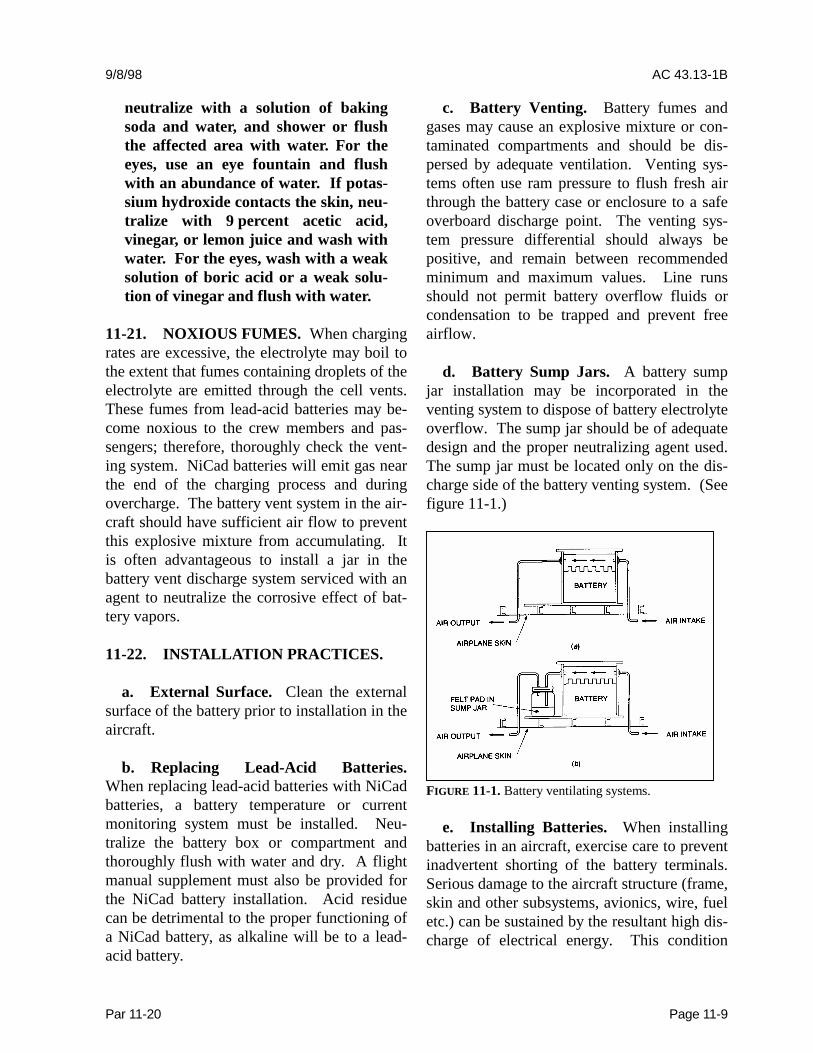
d. Battery Sump Jars. A battery sumpjar installation may be incorporated in theventing system to dispose of battery electrolyteoverflow. The sump jar should be of adequatedesign and the proper neutralizing agent used.The sump jar must be located only on the dis-charge side of the battery venting system. (Seefigure 11-1.)
FIGURE 11-1. Battery ventilating systems.
e. Installing Batteries. When installingbatteries in an aircraft, exercise care to preventinadvertent shorting of the battery terminals.Serious damage to the aircraft structure (frame,skin and other subsystems, avionics, wire, fueletc.) can be sustained by the resultant high dis-charge of electrical energy. This condition
AC 43.13-1B 9/8/98
Page 11-10 Par 11-22
may normally be avoided by insulating theterminal posts during the installation process.
Remove the grounding lead first for batteryremoval, then the positive lead. Connect thegrounding lead of the battery last to minimizethe risk of shorting the “hot terminal” of thebattery during installation.
f. Battery Hold Down Devices. Ensurethat the battery hold down devices are secure,but not so tight as to exert excessive pressurethat may cause the battery to buckle causinginternal shorting of the battery.
g. Quick-Disconnect Type Battery. If aquick-disconnect type of battery connector,that prohibits crossing the battery lead is notemployed, ensure that the aircraft wiring isconnected to the proper battery terminal. Re-verse polarity in an electrical system can seri-ously damage a battery and other electricalcomponents. Ensure that the battery cableconnections are tight to prevent arcing or ahigh resistance connection.
11-23. 11-29. [RESERVED.]
9/27/01 AC 43.13-1B CHG 1
Par 11-30 Page 11-11
SECTION 3. INSPECTION OF EQUIPMENT INSTALLATION
11-30. GENERAL. When installing equip-ment which consumes electrical power in anaircraft, it should be determined that the totalelectrical load can be safely controlled or man-aged within the rated limits of the affectedcomponents of the aircraft’s electrical powersupply system. Addition of most electricalutilization equipment is a major alteration andrequires appropriate FAA approval. The elec-trical load analysis must be prepared in generalaccordance with good engineering practices.Additionally, an addendum to the flight man-ual is generally required.
11-31. INSTALLATION CLEARANCEPROVISIONS. All electrical equipmentshould be installed so that inspection andmaintenance may be performed and that the in-stallation does not interfere with other systems,such as engine or flight controls.
11-32. WIRES, WIRE BUNDLES, ANDCIRCUIT PROTECTIVE DEVICES. Be-fore any aircraft electrical load is increased, thenew total electrical load (previous maximumload plus added load) must be checked to de-termine if the design levels are being ex-ceeded. Where necessary, wires, wire bundles,and circuit protective devices having the cor-rect ratings should be added or replaced.
11-33. ALTERNATOR DIODES. Alter-nators employ diodes for the purpose of con-verting the alternating current to direct current.These diodes are solid-state electronic devicesand are easily damaged by rough handling,abuse, over heating, or reversing the batteryconnections. A voltage surge in the line, if itexceeds the design value, may destroy the di-
ode. The best protection against diode destructionby voltage surges is to make certain that the bat-tery is never disconnected from the aircraft'selectrical system when the alternator is in op-eration. The battery acts as a large capacitorand tends to damp out voltage surges. Thebattery must never be connected with reversedpolarity as this may subject the diodes to aforward bias condition, allowing very high cur-rent conduction that will generally destroythem instantly.
11-34. STATIC ELECTRICAL POWERCONVERTERS. Static power converters em-ploy solid-state devices to convert the aircraft’sprimary electrical source voltage to a differentvoltage or frequency for the operation of radioand electronic equipment. They contain nomoving parts (with the exception of a coolingfan on some models) and are relatively main-tenance free. Various types are available for acto dc or dc to ac conversion.
a. Location of static converters shouldbe carefully chosen to ensure adequate venti-lation for cooling purposes. Heat-radiating finsshould be kept clean of dirt and other foreignmatter that may impair their cooling proper-ties.
b. Static power converters often emit un-acceptable levels of EMI that may disruptcommunication equipment and navigation in-struments. Properly shielded connectors, ter-minal blocks, and wires may be required, withall shields well grounded to the airframe.
CAUTION: Do not load convert-ers beyond their rated capacity.

AC 43.13-1B CHG 1 9/27/01
Page 11-12 Par 11-35
11-35. ACCEPTABLE MEANS OFCONTROLLING OR MONITORING THEELECTRICAL LOAD.
a. Output Rating. The generator or al-ternator output ratings and limits prescribed bythe manufacturer must be checked against theelectrical loads that can be imposed on the af-fected generator or alternator by installedequipment. When electrical load calculationsshow that the total continuous electrical loadcan exceed 80 percent output load limits of thegenerator or alternator, and where special plac-ards or monitoring devices are not installed,the electrical load must be reduced or the gen-erating capacity of the charging system mustbe increased. (This is strictly a “rule of thumb”method and should not be confused with anelectrical load analysis, which is a completeand accurate analysis, which is a complete andaccurate of the composite aircraft powersources and all electrical loads) When a stor-age battery is part of the electrical power sys-tem, the battery will be continuously chargedin flight.
b. The use of placards is recommendedto inform the pilot and/or crew members of thecombination(s) of loads that may be connectedto each power source. Warning lights can beinstalled that will be triggered if the batterybus voltage drops below 13 volts on a 14-voltsystem or 26 volts on a 28-volt system.
c. For installations where the ammeter isin the battery lead, and the regulator systemlimits the maximum current that the generatoror alternator can deliver, a voltmeter can be in-stalled on the system bus. As long as the am-meter never reads “discharge” (except for shortintermittent loads such as operating the gearand flaps) and the voltmeter remains at “sys-tem voltage,” the generator or alternator willnot be overloaded.
d. In installations where the ammeter isin the generator or alternator lead and theregulator system does not limit the maximumcurrent that the generator or alternator can de-liver, the ammeter can be redlined at100 percent of the generator or alternator rat-ing. If the ammeter reading is never allowedto exceed the red line, except for short inter-mittent loads, the generator or alternator willnot be overloaded.
e. Where the use of placards or moni-toring devices is not practical or desired, andwhere assurance is needed that the battery willbe charged in flight, the total continuous con-nected electrical load should be held to ap-proximately 80 percent of the total generatoroutput capacity. When more than one genera-tor is used in parallel, the total rated output isthe combined output of the installed genera-tors.
f. When two or more generators and al-ternators are operated in parallel and the totalconnected system load can exceed the ratedoutput of a single generator, a method shouldbe provided for quickly coping with a suddenoverload that can be caused by generator orengine failure. A quick load reduction systemor procedure should be identified whereby thetotal load can be reduced by the pilot to aquantity within the rated capacity of the re-maining operable generator or generators.
11-36. ELECTRICAL LOAD DETER-MINATION. The connected load of an air-craft’s electrical system may be determined byany one or a combination of several acceptablemethods, techniques, or practices. However,those with a need to know the status of a par-ticular aircraft’s electrical system should haveaccurate and up-to-date data concerning thecapacity of the installed electrical powersource(s) and the load(s) imposed by installedelectrical power-consuming devices. Such
9/27/01 AC 43.13-1B CHG 1
Par 11-38 Page 11-13 (and 11-14)
data should provide a true picture of the statusof the electrical system. New or additionalelectrical devices should not be installed in anaircraft, nor the capacity changed of any powersource, until the status of the electrical systemin the aircraft has been determined accuratelyand found not to adversely affect the integrityof the electrical system.
11-37. JUNCTION BOX CONSTRUC-TION. Replacement junction boxes should befabricated using the same material as the origi-nal or from a fire-resistant, nonabsorbent mate-rial, such as aluminum, or an acceptable plasticmaterial. Where fire-proofing is necessary, astainless steel junction box is recommended.Rigid construction will prevent “oil-canning”of the box sides that could result in internalshort circuits. In all cases, drain holes shouldbe provided in the lowest portion of the box.Cases of electrical power equipment must beinsulated from metallic structure to avoidground fault related fires. (See para-graph 11-7.)
a. Internal Arrangement. The junctionbox arrangement should permit easy access toany installed items of equipment, terminals,and wires. Where marginal clearances are un-avoidable, an insulating material should be in-serted between current carrying parts and anygrounded surface. It is not good practice tomount equipment on the covers or doors ofjunction boxes, since inspection for internalclearance is impossible when the door or coveris in the closed position.
b. Installation. Junction boxes should besecurely mounted to the aircraft structure insuch a manner that the contents are readily ac-cessible for inspection. When possible, theopen side should face downward or at an angleso that loose metallic objects, such as washersor nuts, will tend to fall out of the junction boxrather than wedge between terminals.
c. Wiring. Junction box layouts shouldtake into consideration the necessity for ade-quate wiring space and possible future addi-tions. Electrical wire bundles should be lacedor clamped inside the box so that cables do nottouch other components, prevent ready access,or obscure markings or labels. Cables at en-trance openings should be protected againstchafing by using grommets or other suitablemeans.
11-38. 11-46. [RESERVED.]


9/8/98 AC 43.13-1B
Par 11-47 Page 11-15
SECTION 4. INSPECTION OF CIRCUIT-PROTECTION DEVICES
11-47. GENERAL. All electrical wiresmust be provided with some means of circuitprotection. Electrical wire should be protectedwith circuit breakers or fuses located as closeas possible to the electrical power source bus.Normally, the manufacturer of electricalequipment will specify the fuse or breaker tobe used when installing the respective equip-ment, or SAE publication, ARP 1199, may bereferred to for recommended practices.
11-48. DETERMINATION OF CIRCUITBREAKER RATINGS. Circuit protectiondevices must be sized to supply open circuitcapability. A circuit breaker must be rated sothat it will open before the current rating of thewire attached to it is exceeded, or before thecumulative rating of all loads connected to itare exceeded, whichever is lowest. A circuitbreaker must always open before any compo-nent downstream can overheat and generatesmoke or fire. Wires must be sized to carrycontinuous current in excess of the circuitprotective device rating, including its time-current characteristics, and to avoid excessivevoltage drop. Refer to section 5 for wire ratingmethods.
11-49. DC CIRCUIT PROTECTORCHART. Table 11-3 may be used as a guidefor the selection of circuit breaker and fuserating to protect copper conductor wire. Thischart was prepared for the conditions speci-fied. If actual conditions deviate materiallyfrom those stated, ratings above or below thevalues recommended may be justified. For ex-ample, a wire run individually in the open airmay possibly be protected by the circuitbreaker of the next higher rating to that shownon the chart. In general, the chart is conserva-tive for all ordinary aircraft electri-cal installations.
TABLE 11-3. DC wire and circuit protector chart.
Wire AN gaugecopper Circuit breaker amp. Fuse amp.22201816141210864210
57.510152030405080
100125
55
1010152030507070
100150150
Basis of chart:(1) Wire bundles in 135 °F. ambient and altitudes up to
30,000 feet.(2) Wire bundles of 15 or more wires, with wires carrying
no more than 20 percent of the total current carryingcapacity of the bundle as given in SpecificationMIL-W-5088 (ASG).
(3) Protectors in 75 to 85 °F. ambient.(4) Copper wire Specification MIL-W-5088.(5) Circuit breakers to Specification MIL-C-5809 or
equivalent.(6) Fuses to Specification MIL-F-15160 or equivalent.
11-50. RESETTABLE CIRCUIT PRO-TECTION DEVICES.
a. All resettable type circuit breakersmust open the circuit irrespective of the posi-tion of the operating control when an overloador circuit fault exists. Such circuit breakers arereferred to as “trip free.”
b. Automatic reset circuit breakers, thatautomatically reset themselves periodically, arenot recommended as circuit protection devicesfor aircraft.
11-51. CIRCUIT BREAKER USAGE.Circuit breakers are designed as circuit protec-tion for the wire (see paragraph 11-48and 11-49), not for protection of black boxes

AC 43.13-1B CHG 1 9/27/01
Page 11-16 Par 11-51
or components. Use of a circuit breaker as aswitch is not recommended. Use of a circuitbreaker as a switch will decrease the life of thecircuit breaker.
11-52. CIRCUIT BREAKER MAINTE-NANCE. Circuit breakers should be periodi-cally cycled with no load to enhance contactperformance by cleaning contaminants fromthe contact surfaces.
11-53. SWITCHES. In all circuits where aswitch malfunction can be hazardous, a switchspecifically designed for aircraft service shouldbe used. These switches are of rugged con-struction and have sufficient contact capacityto break, make, and continuously carry theconnected load current. The position of theswitch should be checked with an electricalmeter.
a. Electrical Switch Inspection. Specialattention should be given to electrical circuitswitches, especially the spring-loaded type,during the course of normal airworthiness in-spection. An internal failure of the spring-loaded type may allow the switch to remainclosed even though the toggle or button returnsto the “off” position. During inspection, at-tention should also be given to the possibilitythat improper switch substitution may havebeen made.
(1) With the power off suspect aircraftelectrical switches should be checked in theON position for opens (high resistance) and inThe OFF position for shorts (low resistance),with an ohmmeter.
(2) Any abnormal side to side move-ment of the switch should be an alert to immi-nent failure even if the switch tested wasshown to be acceptable with an ohmmeter.
b. Electromechanical Switches.Switches have electrical contacts and varioustypes of switch actuators (i.e., toggle, plunger,push-button, knob, rocker).
(1) Contacts designed for high-levelloads must not be subsequently used for low-level applications, unless testing has been per-formed to establish this capability.
(2) Switches are specifically selectedbased on the design for the aircraft service cur-rent ratings for lamp loads, inductive loads,and motor loads and must be replaced withidentical make and model switches.
c. Proximity Switches. These switchesare usually solid-state devices that detect thepresence of a predetermined target withoutphysical contact and are usually rated 0.5 ampsor less.
d. Switch Rating. The nominal currentrating of the conventional aircraft switch isusually stamped on the switch housing andrepresents the continuous current rating withthe contacts closed. Switches should be der-ated from their nominal current rating for thefollowing types of circuits:
(1) Circuits containing incandescentlamps can draw an initial current that is15 times greater than the continuous current.Contact burning or welding may occur whenthe switch is closed.
(2) Inductive circuits have magnetic en-ergy stored in solenoid or relay coils that isreleased when the control switch is opened andmay appear as an arc.
(3) Direct-current motors will drawseveral times their rated current during start-ing, and magnetic energy stored in their
9/8/98 AC 43.13-1B
Par 11-53 Page 11-17
armature and field coils is released when thecontrol switch is opened.
e. Switch Selection. Switches for aircraftuse should be selected with extreme caution.The contact ratings should be adequate for allload conditions and applicable voltages, atboth sea level and the operational altitude.Consideration should be given to the variationin the electrical power characteristics, usingMIL-STD-704 as a guide.
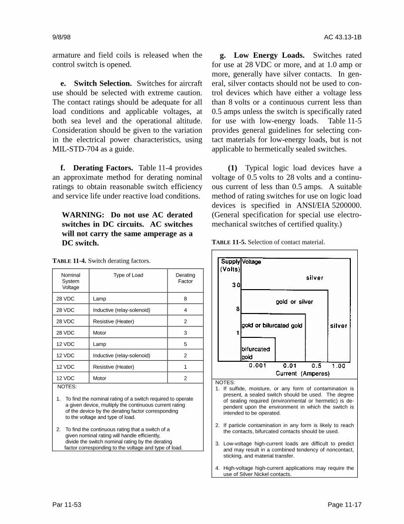
f. Derating Factors. Table 11-4 providesan approximate method for derating nominalratings to obtain reasonable switch efficiencyand service life under reactive load conditions.
WARNING: Do not use AC deratedswitches in DC circuits. AC switcheswill not carry the same amperage as aDC switch.
TABLE 11-4. Switch derating factors.
NominalSystemVoltage
Type of Load DeratingFactor
28 VDC Lamp 8
28 VDC Inductive (relay-solenoid) 4
28 VDC Resistive (Heater) 2
28 VDC Motor 3
12 VDC Lamp 5
12 VDC Inductive (relay-solenoid) 2
12 VDC Resistive (Heater) 1
12 VDC Motor 2NOTES:
1. To find the nominal rating of a switch required to operatea given device, multiply the continuous current ratingof the device by the derating factor correspondingto the voltage and type of load.
2. To find the continuous rating that a switch of agiven nominal rating will handle efficiently,divide the switch nominal rating by the deratingfactor corresponding to the voltage and type of load.
g. Low Energy Loads. Switches ratedfor use at 28 VDC or more, and at 1.0 amp ormore, generally have silver contacts. In gen-eral, silver contacts should not be used to con-trol devices which have either a voltage lessthan 8 volts or a continuous current less than0.5 amps unless the switch is specifically ratedfor use with low-energy loads. Table 11-5provides general guidelines for selecting con-tact materials for low-energy loads, but is notapplicable to hermetically sealed switches.
(1) Typical logic load devices have avoltage of 0.5 volts to 28 volts and a continu-ous current of less than 0.5 amps. A suitablemethod of rating switches for use on logic loaddevices is specified in ANSI/EIA 5200000.(General specification for special use electro-mechanical switches of certified quality.)
TABLE 11-5. Selection of contact material.
NOTES:1. If sulfide, moisture, or any form of contamination is
present, a sealed switch should be used. The degreeof sealing required (environmental or hermetic) is de-pendent upon the environment in which the switch isintended to be operated.
2. If particle contamination in any form is likely to reachthe contacts, bifurcated contacts should be used.
3. Low-voltage high-current loads are difficult to predictand may result in a combined tendency of noncontact,sticking, and material transfer.
4. High-voltage high-current applications may require theuse of Silver Nickel contacts.
AC 43.13-1B CHG 1 9/27/01
Page 11-18 Par 11-53
(2) Typical low-level load devices havea voltage of less than 0.5 volts and a continu-ous current of less than 0.5 amps. A suitablemethod of rating switches for use on logic loaddevices is specified in ANSI/EIA 5200000.
h. Shock and Vibration.
(1) Electromechanical switches (toggleswitches) are most susceptible to shock andvibration in the plane that is parallel to contactmotion. Under these conditions the switchcontacts may momentarily separate.ANSI/EIA 5200000 specifies that contactseparations greater than 10 microseconds andthat closing of open contacts in excess of1 microsecond are failures. Repeated contactseparations during high levels of vibration orshock may cause excessive electrical degrada-tion of the contacts. These separations canalso cause false signals to be registered byelectronic data processors without proper buff-ering.
(2) Although proximity switches do nothave moving parts, the reliability of the inter-nal electronic parts of the switch may be re-duced. Reliability and mean time between-failure (MTBF) calculations should reflect theapplicable environment. Note that the mount-ing of both the proximity sensor and its targetmust be rigid enough to withstand shock or vi-bration to avoid creating false responses.
i. Electromagnetic/Radio Frequency In-terference (EMI/RFI).
(1) DC operated electromechanicalswitches are usually not susceptible toEMI/RFI. Proximity switches are susceptibleto an EMI/RFI environment and must beevaluated in the application. Twisting leadwires, metal overbraids, lead wire routing, andthe design of the proximity switch can mini-mize susceptibility.
(2) The arcing of electromechanicalswitch contacts generates short durationEMI/RFI when controlling highly inductiveelectrical loads. Twisting lead wires, metaloverbraids, and lead wire routing can reduce oreliminate generation problems when dealingwith arcing loads. Proximity sensors generallyuse a relatively low-energy electromagneticfield to sense the target. Adequate spacing isrequired to prevent interference between adja-cent proximity sensors or other devices sus-ceptible to EMI/RFI. Refer to manufacturer’sinstructions.
b. Temperature.
(1) Electromechanical switches canwithstand wide temperature ranges and rapidgradient shifts without damage. Most aircraftswitches operate between -55 °C and 85 °Cwith designs available from -185 °C to 260 °Cor more. Higher temperatures require moreexotic materials, which can increase costs andlimit life. It should be noted that o-ring sealsand elastomer boot seals tend to stiffen in ex-treme cold. This can increase operating forcesand reduce release forces or stop the switchfrom releasing.
(2) Proximity sensors are normally de-signed for environments from -55 °C to125 °C. During temperature excursions, theoperating and release points may shift from5 percent to 10 percent. Reliability of theproximity sensor will typically be highest atroom temperature. The reliability and MTBFestimates should be reduced for use under hightemperatures or high thermal gradients.
c. Sealing.
NOTE: The materials used for sealing(o-rings, potting materials, etc.)should be compatible with any air-craft fluids to which the switch may beexposed.

9/8/98 AC 43.13-1B
Par 11-53 Page 11-19
(1) Electromechanical switches range insealing from partially sealed to hermeticallysealed. Use a sealed switch when the switchwill be exposed to a dirty environment duringstorage, assembly, or operation. Use a higherlevel of sealing when the switch will not havean arcing load to self-clean the contacts. Low-energy loads tend to be more susceptible tocontamination.
(2) Proximity switches for aircraft ap-plications typically have a metal face and pot-ting material surrounding any electronics andlead wire exits. The potting material should becompatible with the fluids the switch will beexposed to in the environment. The plasticsensing face of some proximity switches maybe subject to absorption of water that maycause the operating point to shift should beprotected.
d. Switch Installation. Hazardous errorsin switch operation may be avoided by logicaland consistent installation. “On-off”two-position switches should be mounted sothat the “on” position is reached by an upwardor forward movement of the toggle. When theswitch controls movable aircraft elements,such as landing gear or flaps, the toggle shouldmove in the same direction as the desired mo-tion. Inadvertent operation of switches can beprevented by mounting suitable guards overthe switches.
11-48. RELAYS. A relay is an electricallycontrolled device that opens and closes electri-cal contacts to effect the operation of other de-vices in the same or in another electrical cir-cuit. The relay converts electrical energy intomechanical energy through various means, andthrough mechanical linkages, actuates electri-cal conductors (contacts) that control electricalcircuits. Solid-state relays may also be used inelectrical switching applications.
a. Use of Relays. Most relays are used asa switching device where a weight reductioncan be achieved, or to simplify electrical con-trols. It should be remembered that the relay isan electrically operated switch, and thereforesubject to dropout under low system voltageconditions.
b. Types of Connections. Relays aremanufactured with various connective meansfrom mechanical to plug-in devices. Installa-tion procedures vary by the type of connectionand should be followed to ensure proper op-eration of the relay.
c. Repair. Relays are complicated elec-tromechanical assemblies and most are not re-pairable.
d. Relay Selection.
(1) Contact ratings, as described on therelay case, describe the make, carry, and breakcapability for resistive currents only. Consultthe appropriate specification to determine thederating factor to use for other types of currentloads. (Ref. MIL-PRF-39016, MIL-PRF-5757,MIL-PRF-6016, MIL-PRF-835836.)
(2) Operating a relay at less than nomi-nal coil voltage may compromise its perform-ance and should never be done without writtenmanufacturer approval.
e. Relay Installation and Maintenance.For installation and maintenance, care shouldbe taken to ensure proper placement of hard-ware, especially at electrical connections. Theuse of properly calibrated torque wrenches andfollowing the manufacturer’s installation pro-cedures is strongly recommended. This is es-pecially important with hermetically sealedrelays, since the glass-to-metal seal (used for
AC 43.13-1B CHG 1 9/27/01
Page 11-20 Par 11-54
insulation of the electrically “live” compo-nents) is especially vulnerable to catastrophicfailure as a result of overtorquing.
(1) When replacing relays in alternatingcurrent (ac) applications, it is essential tomaintain proper phase sequencing. For anyapplication involving plug-in relays, properengagement of their retaining mechanism isvital.
(2) The proximity of certain magneti-cally permanent, magnet assisted, coil operatedrelays may cause them to have an impact oneach other. Any manufacturer’s recommenda-tions or precautions must be closely followed.
11-49. LOAD CONSIDERATIONS.When switches or relays are to be used in ap-plications where current or voltage is substan-tially lower than rated conditions, additionalintermediate testing should be performed toensure reliable operation. Contact the manu-facturer on applications different from therated conditions.
11-50. OPERATING CONDITIONS FORSWITCHES AND RELAYS. Switches andrelays should be compared to their specifica-tion rating to ensure that all contacts are madeproperly under all conditions of operation, in-cluding vibration equivalent to that in the areaof the aircraft in which the switch or relay is tobe installed.
11-57. 11-65. [RESERVED.]
9/27/01 AC 43.13-1B CHG 1
Par 11-66 Page 11-21
SECTION 5. ELECTRICAL WIRE RATING
11-66. GENERAL. Wires must be sized sothat they: have sufficient mechanical strengthto allow for service conditions; do not exceedallowable voltage drop levels; are protected bysystem circuit protection devices; and meetcircuit current carrying requirements.
a. Mechanical Strength of Wires. If it isdesirable to use wire sizes smaller than #20,particular attention should be given to the me-chanical strength and installation handling ofthese wires, e.g., vibration, flexing, and termi-nation. Wire containing less than 19 strandsmust not be used. Consideration should begiven to the use of high-strength alloy con-ductors in small gauge wires to increase me-chanical strength. As a general practice, wiressmaller than size #20 should be provided withadditional clamps and be grouped with at leastthree other wires. They should also have ad-ditional support at terminations, such as con-nector grommets, strain relief clamps, shrink-able sleeving, or telescoping bushings. Theyshould not be used in applications where theywill be subjected to excessive vibration, re-peated bending, or frequent disconnectionfrom screw termination.
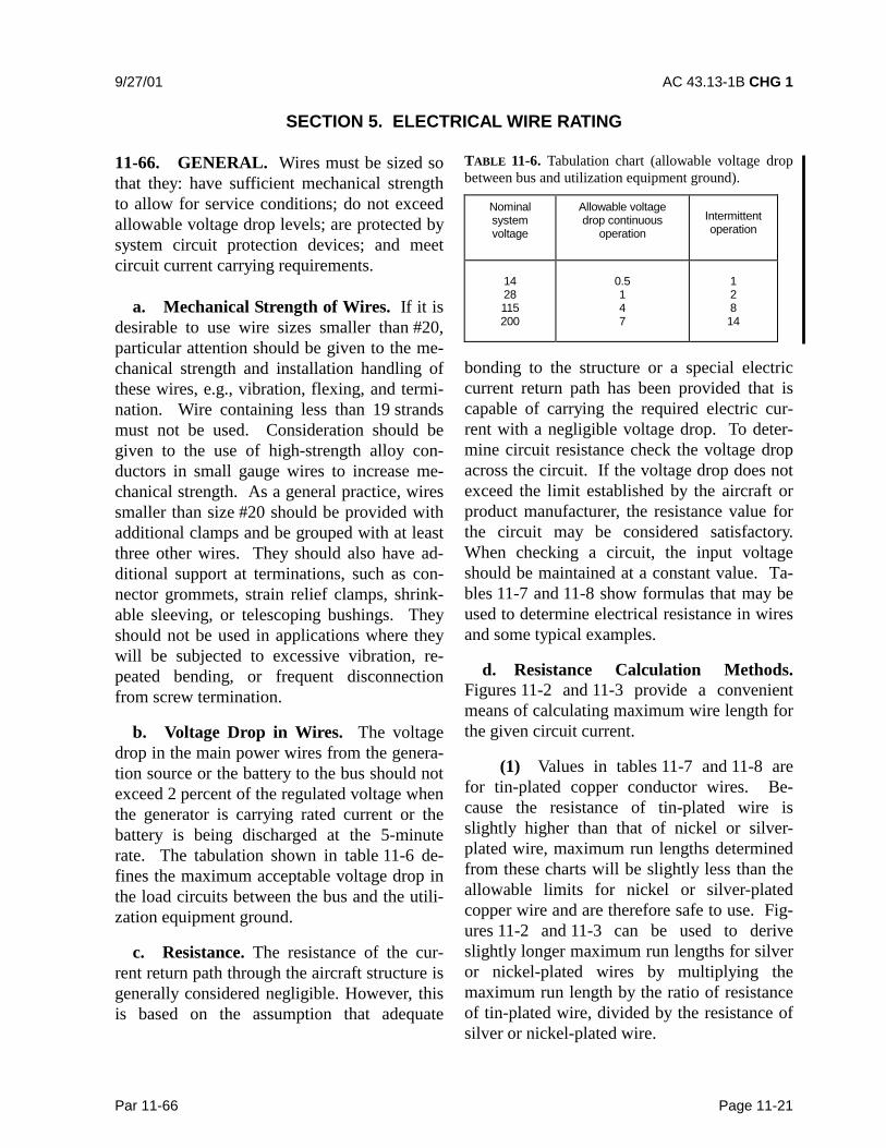
b. Voltage Drop in Wires. The voltagedrop in the main power wires from the genera-tion source or the battery to the bus should notexceed 2 percent of the regulated voltage whenthe generator is carrying rated current or thebattery is being discharged at the 5-minuterate. The tabulation shown in table 11-6 de-fines the maximum acceptable voltage drop inthe load circuits between the bus and the utili-zation equipment ground.
c. Resistance. The resistance of the cur-rent return path through the aircraft structure isgenerally considered negligible. However, thisis based on the assumption that adequate
TABLE 11-6. Tabulation chart (allowable voltage dropbetween bus and utilization equipment ground).
Nominalsystemvoltage
Allowable voltagedrop continuous
operationIntermittentoperation
1428115200
0.5147
12814
bonding to the structure or a special electriccurrent return path has been provided that iscapable of carrying the required electric cur-rent with a negligible voltage drop. To deter-mine circuit resistance check the voltage dropacross the circuit. If the voltage drop does notexceed the limit established by the aircraft orproduct manufacturer, the resistance value forthe circuit may be considered satisfactory.When checking a circuit, the input voltageshould be maintained at a constant value. Ta-bles 11-7 and 11-8 show formulas that may beused to determine electrical resistance in wiresand some typical examples.
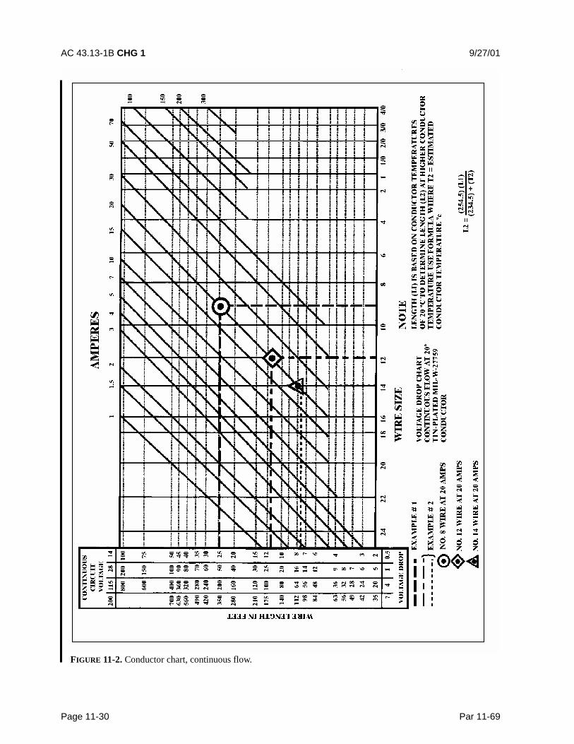
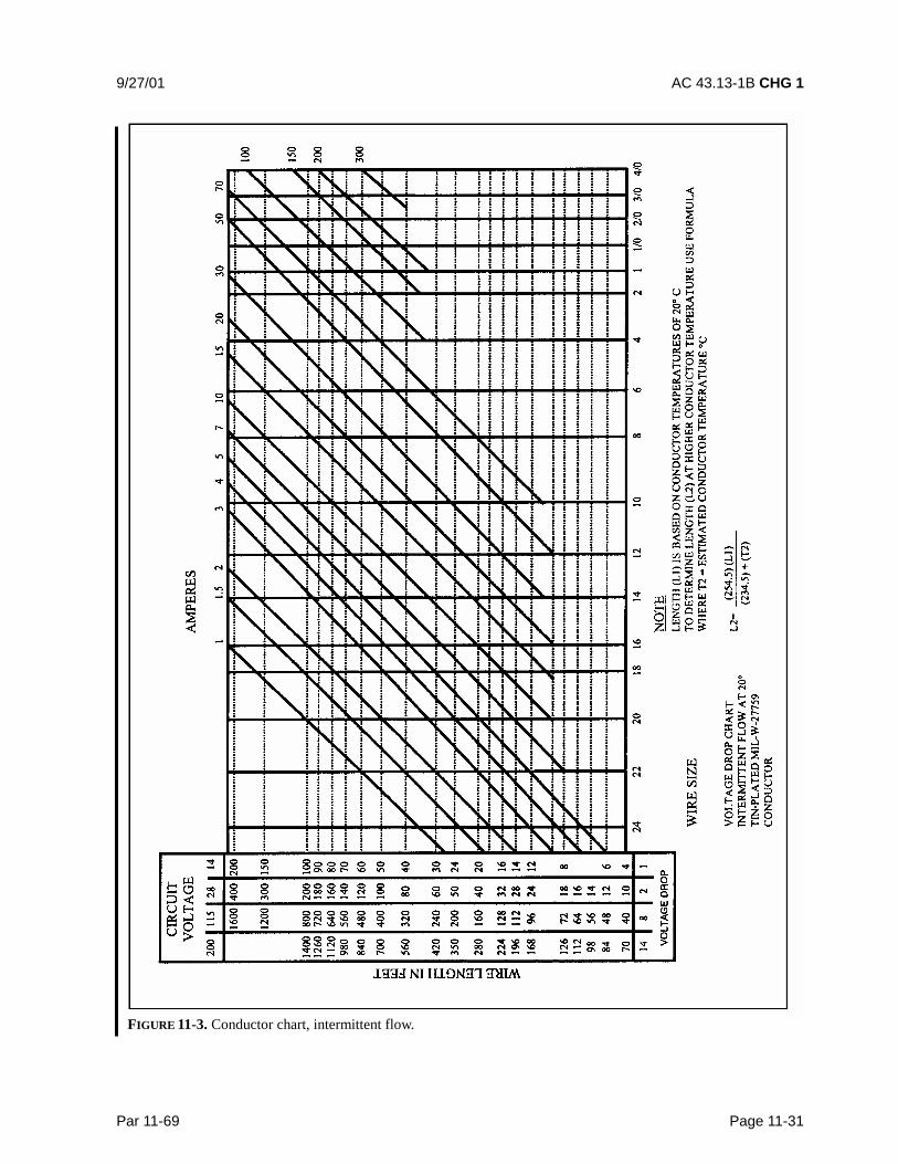
d. Resistance Calculation Methods.Figures 11-2 and 11-3 provide a convenientmeans of calculating maximum wire length forthe given circuit current.
(1) Values in tables 11-7 and 11-8 arefor tin-plated copper conductor wires. Be-cause the resistance of tin-plated wire isslightly higher than that of nickel or silver-plated wire, maximum run lengths determinedfrom these charts will be slightly less than theallowable limits for nickel or silver-platedcopper wire and are therefore safe to use. Fig-ures 11-2 and 11-3 can be used to deriveslightly longer maximum run lengths for silveror nickel-plated wires by multiplying themaximum run length by the ratio of resistanceof tin-plated wire, divided by the resistance ofsilver or nickel-plated wire.

AC 43.13-1B CHG 1 9/27/01
Page 11-22 Par 11-66
TABLE 11-7. Examples of determining required tin-plated copper wire size and checking voltage drop usingfigure 11-2
Voltagedrop
RunLengths(Feet)
CircuitCurrent(Amps)
Wire SizeFromChart
Check-calculated volt-age drop (VD)=(Resistance/Ft)(Length) (Cur-
rent)1 107 20 No. 6 VD= (.00044
ohms/ft)(107)(20)=
0.9420.5 90 20 No. 4 VD= (.00028
ohms/ft)(90)(20)=
0.5044 88 20 No. 12 VD= (.00202
ohms/ft)(88)(20)=
3.607 100 20 No. 14 VD= (.00306
ohms/ft)(100)(20)=
6.12
TABLE 11-8. Examples of determining maximum tin-plated copper wire length and checking voltage dropusing figure 11-2.
MaximumVoltage
dropWireSize
CircuitCurrent(Amps)
MaximumWire RunLength(Feet)
Check-calculatedvoltage drop(VD)= (Resis-
tance/Ft) (Length)(Current)
1 No. 10 20 39 VD= (.00126ohms/ft)
(39)(20)= .980.5 ---- 19.5 VD= (.00126
ohms/ft)(19.5)(20)=
.3664 ---- 156 VD= (.00126
ohms/ft)(156)(20)=
3.937 ---- 273 VD= (.00126
ohms/ft)(273)(20)=
6.88
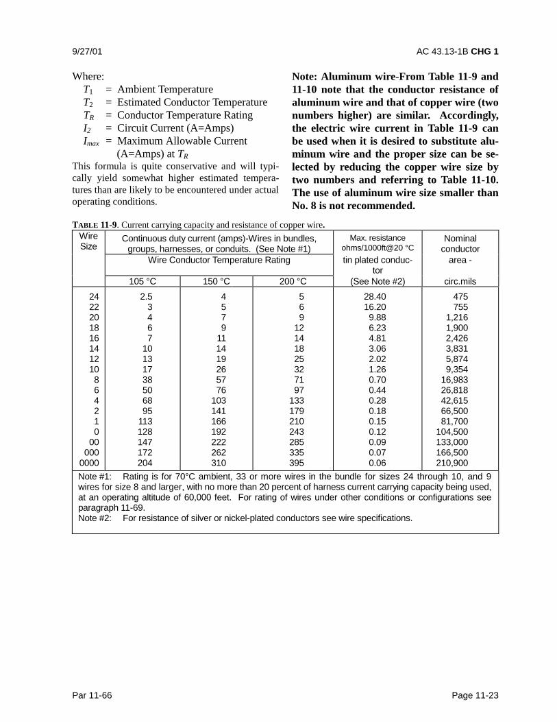
(2) As an alternative method or a meansof checking results from figure 11-2, continu-ous flow resistance for a given wire size can beread from table 11-9 and multiplied by the wirerun length and the circuit current. For inter-mittent flow, use figure 11-3.
(3) Voltage drop calculations for alumi-num wires can be accomplished by multiplyingthe resistance for a given wire size, defined intable 11-10, by the wire run length and circuitcurrent.
(4) When the estimated or measuredconductor temperature (T2) exceeds 20 °C,such as in areas having elevated ambient tem-peratures or in fully loaded power-feed wires,the maximum allowable run length (L2), mustbe shortened from L1 (the 20 °C value) usingthe following formula for copper conductorwire:
))()5.234())(5.254(2
12
TCLCL
+°°
=
For aluminum conductor wire, the formula is:
)()1.238())(1.258(2
12
TCLCL
+°°=
These formulas use the reciprocal of each ma-terial’s resistively temperature coefficient totake into account increased conductor resis-tance resulting from operation at elevated tem-peratures.
(5) To determine T2 for wires carrying ahigh percentage of their current carrying capa-bility at elevated temperatures, laboratorytesting using a load bank and a high-temperature chamber is recommended. Suchtests should be run at anticipated worse caseambient temperature and maximum current-loading combinations.
(6) Approximate T2 can be estimatedusing the following formula:
T T T T I IR2 1 1= + −( )( / max2 )
9/27/01 AC 43.13-1B CHG 1
Par 11-66 Page 11-23
Where: T1 = Ambient Temperature T2 = Estimated Conductor Temperature
TR = Conductor Temperature RatingI2 = Circuit Current (A=Amps)Imax = Maximum Allowable Current
(A=Amps) at TRThis formula is quite conservative and will typi-cally yield somewhat higher estimated tempera-tures than are likely to be encountered under actualoperating conditions.
Note: Aluminum wire-From Table 11-9 and11-10 note that the conductor resistance ofaluminum wire and that of copper wire (twonumbers higher) are similar. Accordingly,the electric wire current in Table 11-9 canbe used when it is desired to substitute alu-minum wire and the proper size can be se-lected by reducing the copper wire size bytwo numbers and referring to Table 11-10.The use of aluminum wire size smaller thanNo. 8 is not recommended.
TABLE 11-9. Current carrying capacity and resistance of copper wire.WireSize
Continuous duty current (amps)-Wires in bundles,groups, harnesses, or conduits. (See Note #1)
Max. resistanceohms/1000ft@20 °C
Nominalconductor
Wire Conductor Temperature Rating tin plated conduc-tor
area -
105 °C 150 °C 200 °C (See Note #2) circ.mils2422201816141210864210
00000
0000
2.53467
10131738506895
113128147172204
4579
111419265776
103141166192222262310
569
12141825327197
133179210243285335395
28.4016.209.886.234.813.062.021.260.700.440.280.180.150.120.090.070.06
475755
1,2161,9002,4263,8315,8749,354
16,98326,81842,61566,50081,700
104,500133,000166,500210,900
Note #1: Rating is for 70°C ambient, 33 or more wires in the bundle for sizes 24 through 10, and 9wires for size 8 and larger, with no more than 20 percent of harness current carrying capacity being used,at an operating altitude of 60,000 feet. For rating of wires under other conditions or configurations seeparagraph 11-69.Note #2: For resistance of silver or nickel-plated conductors see wire specifications.

AC 43.13-1B CHG 1 9/27/01
Page 11-24 Par 11-66
TABLE 11-10. Current carrying capacity and resistance of aluminum wire.
Wire SizeContinuous duty current (amps)Wires in bundles, groups or harnessesor conduits (See table 11-9 Note #1)
Max. resistanceohms/1000ft
Wire conductor temperature rating @ 20 °C105 °C 150 °C
864210
00000
0000
3040547690
102117138163
456182
113133153178209248
1.0930.6410.4270.2680.2140.1690.1330.1090.085
Note: Observe design practices described in paragraph 11-67 for aluminum conductor
9/27/01 AC 43.13-1B CHG 1
Par 11-67 Page 11-25
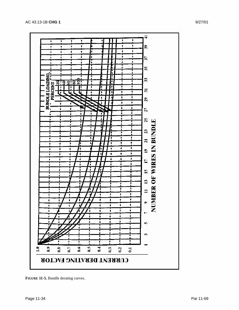
11-67. METHODS FOR DETERMININGCURRENT CARRYING CAPACITY OFWIRES. This paragraph contains methods fordetermining the current carrying capacity ofelectrical wire, both as a single wire in free airand when bundled into a harness. It presentsderating factors for altitude correction and ex-amples showing how to use the graphical andtabular data provided for this purpose. Insome instances, the wire may be capable ofcarrying more current than is recommended forthe contacts of the related connector. In thisinstance, it is the contact rating that dictatesthe maximum current to be carried by a wire.Wires of larger gauge may need to be used tofit within the crimp range of connector con-tacts that are adequately rated for the currentbeing carried. Figure 11-5 gives a family ofcurves whereby the bundle derating factor maybe obtained.
a. Effects of Heat Aging on Wire Insula-tion. Since electrical wire may be installed inareas where inspection is infrequent over ex-tended periods of time, it is necessary to givespecial consideration to heat-aging character-istics in the selection of wire. Resistance toheat is of primary importance in the selectionof wire for aircraft use, as it is the basic factorin wire rating. Where wire may be required tooperate at higher temperatures due either tohigh ambient temperatures, high-current load-ing, or a combination of the two, selectionshould be made on the basis of satisfactoryperformance under the most severe operatingconditions.
b. Maximum Operating Temperature.The current that causes a temperature steadystate condition equal to the rated temperatureof the wire should not be exceeded. Ratedtemperature of the wire may be based upon theability of either the conductor or the insulationto withstand continuous operation without deg-radation.
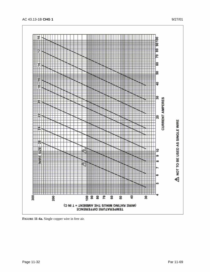
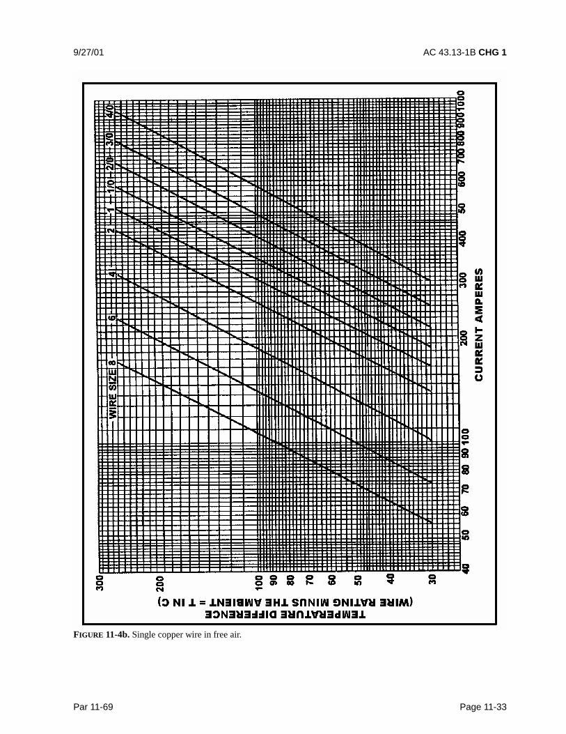
c. Single Wire in Free Air. Determininga wiring system’s current carrying capacity be-gins with determining the maximum currentthat a given-sized wire can carry without ex-ceeding the allowable temperature difference(wire rating minus ambient °C). The curvesare based upon a single copper wire in free air.(See figures 11-4a and 11-4b.)
d. Wires in a Harness. When wires arebundled into harnesses, the current derived fora single wire must be reduced as shown in fig-ure 11-5. The amount of current derating is afunction of the number of wires in the bundleand the percentage of the total wire bundle ca-pacity that is being used.
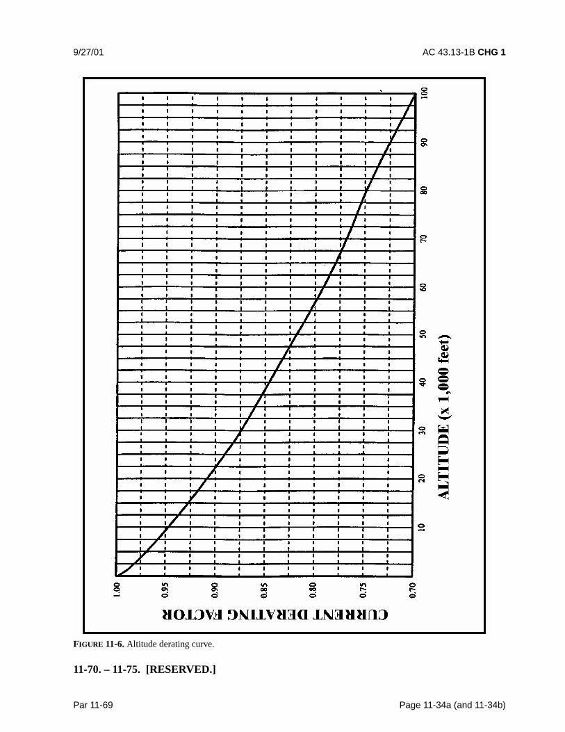
e. Harness at Altitude. Since heat lossfrom the bundle is reduced with increased al-titude, the amount of current should be de-rated. Figure 11-6 gives a curve whereby thealtitude-derating factor may be obtained.
f. Aluminum Conductor Wire. Whenaluminum conductor wire is used, sizes shouldbe selected on the basis of current ratingsshown in table 11-10. The use of sizes smallerthan #8 is discouraged (Ref. AS50881A).Aluminum wire should not be attached to en-gine mounted accessories or used in areashaving corrosive fumes, severe vibration, me-chanical stresses, or where there is a need forfrequent disconnection. Use of aluminum wireis also discouraged for runs of less than 3 feet(AS50991A). Termination hardware should beof the type specifically designed for use withaluminum conductor wiring.
11-68. INSTRUCTIONS FOR USE OFELECTRICAL WIRE CHART.
a. Correct Size. To select the correct sizeof electrical wire, two major requirementsmust be met:

AC 43.13-1B CHG 1 9/27/01
Page 11-26 Par 11-68
(1) The wire size should be sufficient toprevent an excessive voltage drop while car-rying the required current over the requireddistance. (See table 11-6, Tabulation Chart, forallowable voltage drops.)
(2) The size should be sufficient to pre-vent overheating of the wire carrying the re-quired current. (See paragraph 11-69 for al-lowable current carrying calculation methods.)
b. Two Requirements. To meet the tworequirements (see paragraph 11-66b) in se-lecting the correct wire size using figure 11-2or figure 11-3, the following must be known:
(1) The wire length in feet.
(2) The number of amperes of current tobe carried.
(3) The allowable voltage droppermitted.
(4) The required continuous or inter-mittent current.
(5) The estimated or measured con-ductor temperature.
(6) Is the wire to be installed in conduitand/or bundle?
(7) Is the wire to be installed as a singlewire in free air?
c. Example No. 1. Find the wire size infigure 11-2 using the following known infor-mation:
(1) The wire run is 50 feet long, in-cluding the ground wire.
(2) Current load is 20 amps.(3) The voltage source is 28 volts from
bus to equipment.
(4) The circuit has continuous opera-tion.
(5) Estimated conductor temperature is20 °C or less.
The scale on the left of the chart representsmaximum wire length in feet to prevent an ex-cessive voltage drop for a specified voltagesource system (e.g., 14V, 28V, 115V, 200V).This voltage is identified at the top of scaleand the corresponding voltage drop limit forcontinuous operation at the bottom. The scale(slant lines) on top of the chart represents am-peres. The scale at the bottom of the chart rep-resents wire gauge.
STEP 1: From the left scale find the wirelength, 50 feet under the 28V source column.
STEP 2: Follow the corresponding horizontalline to the right until it intersects the slantedline for the 20-amp load.
STEP 3: At this point, drop vertically to thebottom of the chart. The value falls betweenNo. 8 and No. 10. Select the next larger sizewire to the right, in this case No. 8. This is thesmallest size wire that can be used without ex-ceeding the voltage drop limit expressed at thebottom of the left scale. This example is plot-ted on the wire chart, figure 11-2. Use figure11-2 for continuous flow and figure 11-3 forintermittent flow.
d. Procedures in Example No. 1 para-graph 11-68c, can be used to find the wire sizefor any continuous or intermittent operation(maximum two minutes). Voltage (e.g.14 volts, 28 volts, 115 volts, 200 volts) as in-dicated on the left scale of the wire chart infigure 11-2 and 11-3.
e. Example No. 2. Using figure 11-2, findthe wire size required to meet the allowablevoltage drop in table 11-6 for a wire carrying

9/27/01 AC 43.13-1B CHG 1
Par 11-67 Page 11-27
current at an elevated conductor temperatureusing the following information:
(1) The wire run is 15.5 feet long, in-cluding the ground wire.
(2) Circuit current (I2) is 20 amps,continuous.
(3) The voltage source is 28 volts.
(4) The wire type used has a 200 °Cconductor rating and it is intended to use thisthermal rating to minimize the wire gauge.Assume that the method described in para-graph 11-66d(6) was used and the minimumwire size to carry the required current is #14.
(5) Ambient temperature is 50 °C underhottest operating conditions.
f. Procedures in example No. 2.
STEP 1: Assuming that the recommendedload bank testing described in para-graph 11-66d(5) is unable to be conducted,then the estimated calculation methods out-lined in paragraph 11-66d(6) may be used todetermine the estimated maximum current(Imax). The #14 gauge wire mentioned abovecan carry the required current at 50 °C ambient(allowing for altitude and bundle derating).
(1) Use figure 11-4a to calculate theImax a #14 gauge wire can carry.
Where:
T2 = estimated conductor temperature
T1 = 50 °C ambient temperature
TR = 200 °C maximum conductor rated temperature
(2) Find the temperature differences(TR-T1) = (200 °C-50 °C) = 150 °C.
(3) Follow the 150 °C correspondinghorizontal line to intersect with #14 wire size,drop vertically and read 47 Amps at bottom ofchart (current amperes).
(4) Use figure 11-5, left side of chartreads 0.91 for 20,000 feet, multiple0.91 x 47 Amps = 42.77 Amps.
(5) Use figure 11-6, find the deratefactor for 8 wires in a bundle at 60 percent.First find the number of wires in the bundle (8)at bottom of graph and intersect with the60 percent curve meet. Read derating factor,(left side of graph) which is 0.6. Multiply0.6 x 42.77 Amps = 26 Amps.
Imax = 26 amps (this is the maximumcurrent the #14 gauge wire could carry at 50°Cambient
L1=15.5 feet maximum run length for size#14 wire carrying 20 amps from figure 11-2
STEP 2: From paragraph 11-66d (5) and (6),determine the T2 and the resultant maximumwire length when the increased resistance ofthe higher temperature conductor is taken intoaccount.
( )( )T T T T I IR2 1 1 2= + − / max
AACCC 26/20)(50200(50T2 −+= °
= 50 °C+(150 °C)(.877)T2 = 182 °C
=°°
)(T+C)(234.5)C)(L(254.5=L2
12
L2 = C)(182+C)(234.5
C)(15.5Ft)(254.5°°
°
L2 = 9.5 ft
AC 43.13-1B CHG 1 9/27/01
Page 11-28 Par 11-68
The size #14 wire selected using the methodsoutlined in paragraph 11-66d is too small tomeet the voltage drop limits from figure 11-2for a 15.5 feet long wire run.
STEP 3: Select the next larger wire (size #12)and repeat the calculations as follows:
L1=24 feet maximum run length for12 gauge wire carrying 20 amps from fig-ure 11-2.
Imax = 37 amps (this is the maximum currentthe size #12 wire can carry at 50 °C ambient.Use calculation methods outlined in para-graph 11-69 and figure 11-4a.
ft 7.16366
C)(24ft)5.254(L
3666108
C)(131+C)(234.5C)(24ft)5.254(L
)(T+C5.234)C(L5.254L
C 131=C)(-540)(150+C5037/20( C)50-C(200+C50T
o
2
oo
o
2
2o
1o
2
ooo
ooo2
==
==
=
== AA
The resultant maximum wire length, after ad-justing downward for the added resistance as-sociated with running the wire at a higher tem-perature, is 15.4 feet, which will meet theoriginal 15.5 foot wire run length requirementwithout exceeding the voltage drop limit ex-pressed in figure 11-2.
11-69. COMPUTING CURRENT CARRY-ING CAPACITY.
a. Example 1. Assume a harness (open orbraided), consisting of 10 wires, size #20,200 °C rated copper and 25 wires, size #22,200 °C rated copper, will be installed in anarea where the ambient temperature is 60 °Cand the vehicle is capable of operating at a60,000-foot altitude. Circuit analysis revealsthat 7 of the 35 wires in the bundle
(7/35 = 20 percent) will be carrying power cur-rents nearly at or up to capacity.
STEP 1: Refer to the “single wire in free air”curves in figure 11-4a. Determine the changeof temperature of the wire to determine free airratings. Since the wire will be in an ambientof 60 ºC and rated at 200° C, the change of totemperature is 200 °C - 60 °C = 140 °C. Fol-low the 140 °C temperature difference hori-zontally until it intersects with wire size lineon figure 11-4a. The free air rating forsize #20 is 21.5 amps, and the free air ratingfor size #22 is 16.2 amps.
STEP 2: Refer to the “bundle derating curves”in figure 11-5, the 20 percent curve is selectedsince circuit analysis indicate that 20 percentor less of the wire in the harness would be car-rying power currents and less than 20 percentof the bundle capacity would be used. Find35 (on the abscissa) since there are 35 wires inthe bundle and determine a derating factor of0.52 (on the ordinate) from the 20 percentcurve.
STEP 3: Derate the size #22 free air rating bymultiplying 16.2 by 0.52 to get 8.4 amps in-harness rating. Derate the size #20 free air-rating by multiplying 21.5 by 0.52 to get11.2 amps in-harness rating.
STEP 4: Refer to the “altitude derating curve”of figure 11-6, look for 60,000 feet (on the ab-scissa) since that is the altitude at which thevehicle will be operating. Note that the wiremust be derated by a factor of 0.79 (found onthe ordinate). Derate the size#22 harness rating by multiplying8.4 amps by 0.79 to get 6.6 amps. Derate thesize #20 harness rating by multiplying11.2 amps by 0.79 to get 8.8 amps.
STEP 5: To find the total harness capacity,multiply the total number of size #22 wires bythe derated capacity (25 x 6.6 = 165.0 amps)and add to that the number of size #20 wires
9/27/01 AC 43.13-1B CHG 1
Par 11-67 Page 11-29
multiplied by the derated capacity(10 x 8.8 = 88 amps) and multiply the sum bythe 20 percent harness capacity factor. Thus,the total harness capacity is(165.0 + 88.0) x 0.20 = 50.6 amps. It has beendetermined that the total harness currentshould not exceed 50.6 A, size #22 wire shouldnot carry more than 6.6 amps and size#20 wire should not carry more than 8.8 amps.
STEP 6: Determine the actual circuit currentfor each wire in the bundle and for the wholebundle. If the values calculated in step #5 areexceeded, select the next larger size wire andrepeat the calculations.
b. Example 2. Assume a harness (open orbraided), consisting of 12, size #12, 200 °Crated copper wires, will be operated in an am-bient of 25 °C at sea level and 60 °C at a20,000-foot altitude. All 12 wires will be op-erated at or near their maximum capacity.
STEP 1: Refer to the “single wire in free air”curve in figure 11-4a, determine the tempera-ture difference of the wire to determine free airratings. Since the wire will be in ambient of25 °C and 60 °C and is rated at 200 °C, thetemperature differences are 200 °C-25 °C =175 °C and 200 °C-60 °C = 140 °C respec-tively. Follow the 175 °C and the 140 °C tem-perature difference lines on figure 11-4a untileach intersects wire size line, the free air rat-ings of size #12 are 68 amps and 61 amps, re-spectively.
STEP 2: Refer to the “bundling deratingcurves” in figure 11-5, the 100 percent curve is
selected because we know all 12 wires will becarrying full load. Find 12 (on the abscissa)since there are 12 wires in the bundle and de-termine a derating factor of 0.43 (on the ordi-nate) from the 100 percent curve.
STEP 3: Derate the size #12 free air ratings bymultiplying 68 amps and 61 amps by 0.43 toget 29.2 amps and 26.2 amps, respectively.
STEP 4: Refer to the “altitude derating curve”of figure 11-6, look for sea level and20,000 feet (on the abscissa) since these arethe conditions at which the load will be car-ried. The wire must be derated by a factor of1.0 and 0.91, respectively.
STEP 5: Derate the size #12 in a bundle rat-ings by multiplying 29.2 amps at sea level and26.6 amps at 20,000 feet by 1.0 and 0.91, re-spectively, to obtained 29.2 amps and23.8 amps. The total bundle capacity at sealevel and 25 °C ambient is29.2x12=350.4 amps. At 20,000 feet and60 °C ambient the bundle capacity is23.8x12=285.6 amps. Each size #12 wire cancarry 29.2 amps at sea level, 25 °C ambient or23.8 amps at 20,000 feet, and 60 °C ambient.
STEP 6: Determine the actual circuit currentfor each wire in the bundle and for the bundle.If the values calculated in Step #5 are ex-ceeded, select the next larger size wire and re-peat the calculations.
AC 43.13-1B CHG 1 9/27/01
Page 11-30 Par 11-69
FIGURE 11-2. Conductor chart, continuous flow.
9/27/01 AC 43.13-1B CHG 1
Par 11-69 Page 11-31
FIGURE 11-3. Conductor chart, intermittent flow.
AC 43.13-1B CHG 1 9/27/01
Page 11-32 Par 11-69
FIGURE 11-4a. Single copper wire in free air.
9/27/01 AC 43.13-1B CHG 1
Par 11-69 Page 11-33
FIGURE 11-4b. Single copper wire in free air.
AC 43.13-1B CHG 1 9/27/01
Page 11-34 Par 11-69
FIGURE 11-5. Bundle derating curves.
9/27/01 AC 43.13-1B CHG 1
Par 11-69 Page 11-34a (and 11-34b)
FIGURE 11-6. Altitude derating curve.
11-70. – 11-75. [RESERVED.]

9/8/98 AC 43.13-1B
Par 11-78 Page 11-35
SECTION 6. AIRCRAFT ELECTRICAL WIRE SELECTION
11-76. GENERAL. Aircraft service im-poses severe environmental condition on elec-trical wire. To ensure satisfactory service, in-spect wire annually for abrasions, defective in-sulation, condition of terminations, and poten-tial corrosion. Grounding connections forpower, distribution equipment, and electro-magnetic shielding must be given particularattention to ensure that electrical bonding re-sistance has not been significantly increased bythe loosening of connections or corrosion.
a. Wire Size. Wires must have sufficientmechanical strength to allow for service con-ditions. Do not exceed allowable voltage droplevels. Ensure that the wires are protected bysystem circuit protection devices, and that theymeet circuit current carrying requirements. Ifit is desirable to use wire sizes smallerthan #20, particular attention should be givento the mechanical strength and installationhandling of these wires, e.g. vibration, flexing,and termination. When used in interconnect-ing airframe application, #24 gauge wire mustbe made of high strength alloy.
b. Installation Precautions for SmallWires. As a general practice, wires smallerthan size #20 must be provided with additionalclamps, grouped with at least three other wires,and have additional support at terminations,such as connector grommets, strain-reliefclamps, shrinkable sleeving, or telescopingbushings. They should not be used in applica-tions where they will be subjected to excessivevibration, repeated bending, or frequent dis-connection from screw terminations.
c. Identification. All wire used on air-craft must have its type identification im-printed along its length. It is common practiceto follow this part number with the fivedigit/letter Commercial and Government En-tity (C.A.G.E). code identifying the wire
manufacturer. Existing installed wire thatneeds replacement can thereby be identified asto its performance capabilities, and the inad-vertent use of a lower performance and unsuit-able replacement wire avoided.
(1) In addition to the type identificationimprinted by the original wire manufacturer,aircraft wire also contains its unique circuitidentification coding that is put on at the timeof harness assembly. The traditional “HotStamp” method has not been totally satisfac-tory in recent years when used on modern, ul-tra-thin-walled installations. Fracture of theinsulation wall and penetration to the conduc-tor of these materials by the stamping dieshave occurred. Later in service, when theseopenings have been wetted by various fluids,serious arcing and surface tracking have dam-aged wire bundles.
(2) Extreme care must be taken duringcircuit identification by a hot stamp machineon wire with a 10 mil wall or thinner. Alter-native identification methods, such as “LaserPrinting” and “Ink Jet,” are coming into in-creasing use by the industry. When such mod-ern equipment is not available, the use ofstamped identification sleeving should be con-sidered on thin-walled wire, especially wheninsulation wall thickness falls below 10 mils.
11-77. AIRCRAFT WIRE MATERIALS.Only wire, specifically designed for airborneuse, must be installed in aircraft.
a. Authentic Aircraft Wire. Most air-craft wire designs are to specifications that re-quire manufacturers to pass rigorous testing ofwires before being added to a Qualified Prod-ucts List (QPL) and being permitted to producethe wire. Aircraft manufacturers who maintaintheir own wire specifications invariably exer-cise close control on their approved
AC 43.13-1B CHG 1 9/27/01
Page 11-36 Par 11-77
sources. Such military or original equipmentmanufacturer (OEM) wire used on aircraftshould only have originated from these definedwire mills. Aircraft wire from other unau-thorized firms, and fraudulently marked withthe specified identification, must be regardedas “unapproved wire,” and usually will be ofinferior quality with little or no process controltesting. Efforts must be taken to ensure ob-taining authentic, fully tested aircraft wire.
b. Plating. Bare copper develops a sur-face oxide coating at a rate dependent on tem-perature. This oxide film is a poor conductorof electricity and inhibits determination ofwire. Therefore, all aircraft wiring has a coat-ing of tin, silver, or nickel, that have far sloweroxidation rates.
(1) Tin coated copper is a very commonplating material. Its ability to be successfullysoldered without highly active fluxes dimin-ishes rapidly with time after manufacture. Itcan be used up to the limiting temperature of150 °C.
(2) Silver-coated wire is used wheretemperatures do not exceed 200 °C (392 °F).
(3) Nickel coated wire retains its prop-erties beyond 260 °C, but most aircraft wireusing such coated strands have insulation sys-tems that cannot exceed that temperature onlong-term exposure. Soldered terminations ofnickel-plated conductor require the use of dif-ferent solder sleeves or flux than those usedwith tin or silver-plated conductor.
c. Conductor Stranding. Because offlight vibration and flexing, conductor roundwire should be stranded to minimize fatiguebreakage.
d. Wire Construction Versus Applica-tion. The most important consideration in theselection of aircraft wire is properly matchingthe wire’s construction to the application envi-
ronment. Wire construction that is suitable forthe most severe environmental condition to beencountered should be selected. Wires aretypically categorized as being suitable for ei-ther “open wiring” or “protected wiring” ap-plications. MIL-W-5088L, replaced byAS50881A, wiring aerospace vehicle, Appen-dix A table A-I lists wires considered to havesufficient abrasion and cut-through resistanceto be suitable for open-harness construction.MIL-W-5088L, replaced by AS50881A, wiringaerospace vehicle, Appendix A table A-II listswires for protected applications. These wiresare not recommended for aircraft interconnec-tion wiring unless the subject harness is cov-ered throughout its length by a protectivejacket. The wire temperature rating is typicallya measure of the insulation’s ability to with-stand the combination of ambient temperatureand current related conductor temperature rise.
e. Insulation. There are many insulationmaterials and combinations used on aircraftelectrical wire. Characteristics should be cho-sen based on environment; such as abrasion re-sistance, arc resistance, corrosion resistance,cut-through strength, dielectric strength, flameresistant, mechanical strength, smoke emis-sion, fluid resistance, and heat distortion. Anexplanation of many of the abbreviations isidentified in the glossary.
11-78. SUBSTITUTIONS. In the repairand modification of existing aircraft, when areplacement wire is required, the maintenancemanual for that aircraft must first be reviewedto determine if the original aircraft manufac-turer (OAM) has approved any substitution. Ifnot, then the OAM must be contacted for anacceptable replacement.
a. MIL-W-5088L, replaced by AS50881A,wiring aerospace vehicle, Appendix A lists wiretypes that have been approved for military
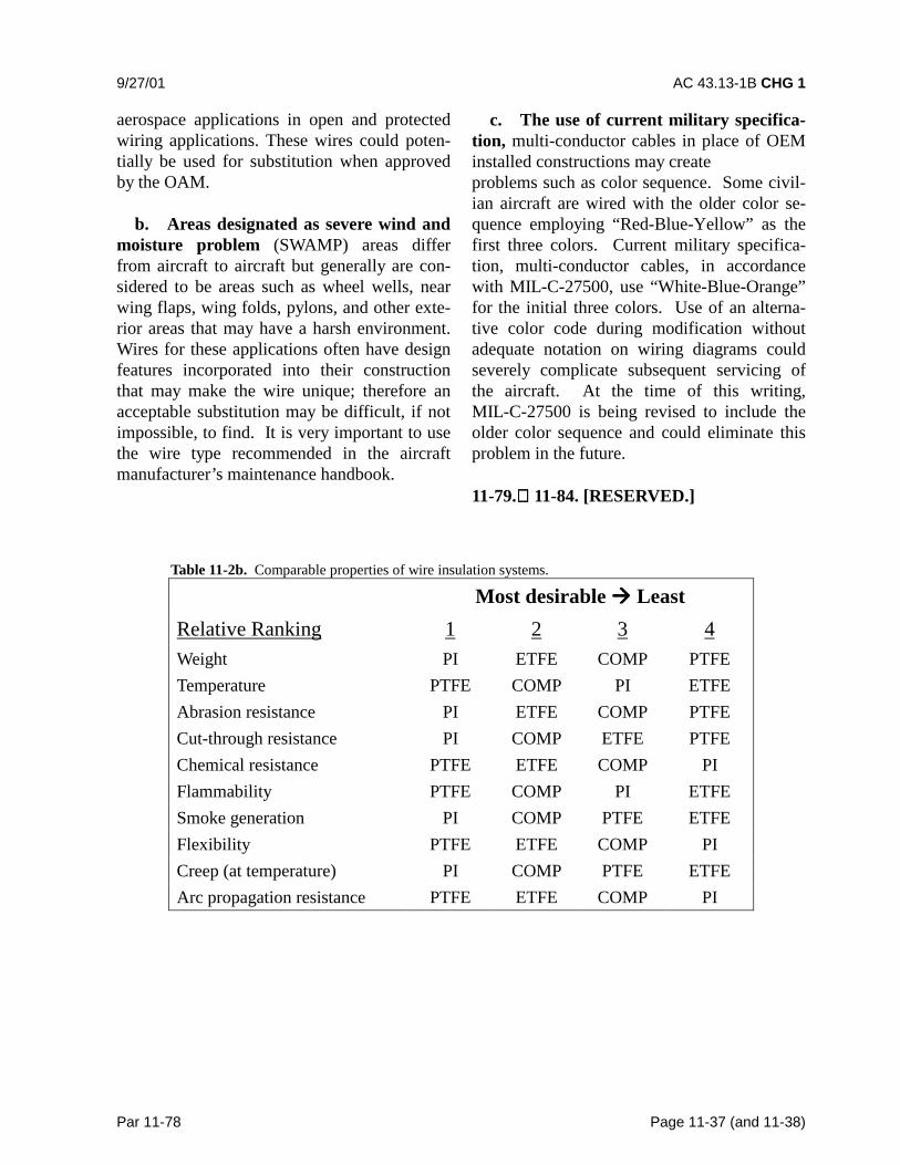
9/27/01 AC 43.13-1B CHG 1
Par 11-78 Page 11-37 (and 11-38)
aerospace applications in open and protectedwiring applications. These wires could poten-tially be used for substitution when approvedby the OAM.
b. Areas designated as severe wind andmoisture problem (SWAMP) areas differfrom aircraft to aircraft but generally are con-sidered to be areas such as wheel wells, nearwing flaps, wing folds, pylons, and other exte-rior areas that may have a harsh environment.Wires for these applications often have designfeatures incorporated into their constructionthat may make the wire unique; therefore anacceptable substitution may be difficult, if notimpossible, to find. It is very important to usethe wire type recommended in the aircraftmanufacturer’s maintenance handbook.
c. The use of current military specifica-tion, multi-conductor cables in place of OEMinstalled constructions may createproblems such as color sequence. Some civil-ian aircraft are wired with the older color se-quence employing “Red-Blue-Yellow” as thefirst three colors. Current military specifica-tion, multi-conductor cables, in accordancewith MIL-C-27500, use “White-Blue-Orange”for the initial three colors. Use of an alterna-tive color code during modification withoutadequate notation on wiring diagrams couldseverely complicate subsequent servicing ofthe aircraft. At the time of this writing,MIL-C-27500 is being revised to include theolder color sequence and could eliminate thisproblem in the future.
11-79. 11-84. [RESERVED.]
Table 11-2b. Comparable properties of wire insulation systems.
Most desirable ���� LeastRelative Ranking 1 2 3 4Weight PI ETFE COMP PTFETemperature PTFE COMP PI ETFEAbrasion resistance PI ETFE COMP PTFECut-through resistance PI COMP ETFE PTFEChemical resistance PTFE ETFE COMP PIFlammability PTFE COMP PI ETFESmoke generation PI COMP PTFE ETFEFlexibility PTFE ETFE COMP PICreep (at temperature) PI COMP PTFE ETFEArc propagation resistance PTFE ETFE COMP PI

9/27/01 AC 43.13-1B CHG 1
Par 11-85 Pages 11-39
SECTION 7. TABLE OF ACCEPTABLE WIRES
11-85. AIRCRAFT WIRE TABLE. Ta-bles 11-11 and 11-12 list wires used for thetransmission of signal and power currents inaircraft. It does not include special purposewires such as thermocouple, engine vibrationmonitor wire, fiber optics, data bus, and othersuch wire designs. Fire resistant wire is in-cluded because it is experiencing a wider ap-plication in aircraft circuits beyond that of thefire detection systems.
a. All wires in tables 11-11 and 11-12have been determined to meet the flammabilityrequirements of Title 14 of the Code of FederalRegulation (14 CFR) part 25, section25.869(a)(4) and the applicable portion ofpart 1 of Appendix F of part 25.
b. The absence of any wire from ta-bles 11-11 and 11-12 are not to be construed asbeing unacceptable for use in aircraft. How-ever, the listed wires have all been reviewedfor such use and have been found suitable, orhave a successful history of such usage.
c. Explanations of the various insulationmaterials mentioned in table 11-11, by abbre-viations, can be found in the glossary.
11-86. OPEN AIRFRAME INTERCON-NECTING WIRE. Interconnecting wire isused in point to point open harnesses, normallyin the interior or pressurized fuselage, witheach wire providing enough insulation to resistdamage from handling and service exposure.(See table 11-11.) Electrical wiring is often in-stalled in aircraft without special enclosingmeans. This practice is known as open wiringand offers the advantages of ease of mainte-nance and reduced weight.
11-87. PROTECTED WIRE. Airbornewire that is used within equipment boxes, orhas additional protection, such as an exterior
jacket, conduit, tray, or other covering isknown as protected wire. (See table 11-12.)
11-88. SEVERE WIND AND MOISTUREPROBLEMS (SWAMP). Areas such aswheel wells, wing fold and pylons, flap areas,and those areas exposed to extended weathershall dictate selection and will require specialconsideration. Insulation or jacketing will varyaccording to the environment. Suitable wiretypes selected from MIL-W-22759 shall beused in these applications. (See table 11-11.)
Suitable wire types selected fromMIL-W-22759 are preferred for areas that re-quire repeated bending and flexing of the wire.Consideration should be made to areas that re-quire frequent component removal or repair.(See table 11-11.)
11-89. SHIELDED WIRE. With the in-crease in number of highly sensitive electronicdevices found on modern aircraft, it has be-come very important to ensure proper shield-ing for many electric circuits. Shielding is theprocess of applying a metallic covering towiring and equipment to eliminate interferencecaused by stray electromagnetic energy.Shielded wire or cable is typically connected tothe aircraft’s ground at both ends of the wire,or at connectors in the cable. ElectromagneticInterference (EMI) is caused when electro-magnetic fields (radio waves) induce high-frequency (HF) voltages in a wire or compo-nent. The induced voltage can cause systeminaccuracies or even failure, therefore puttingthe aircraft and passengers at risk. Shieldinghelps to eliminate EMI by protecting the pri-mary conductor with an outer conductor. Re-fer to MIL-DTL-27500, Cable, Power, Electri-cal and Cable Special Purpose, ElectricalShielded and Unshielded General Specifica-tions.
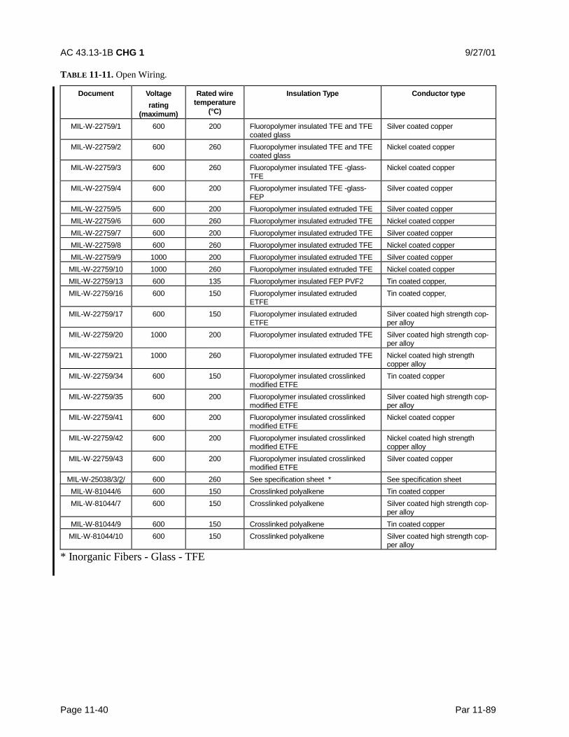
AC 43.13-1B CHG 1 9/27/01
Page 11-40 Par 11-89
TABLE 11-11. Open Wiring.
Document Voltagerating
(maximum)
Rated wiretemperature
(°C)
Insulation Type Conductor type
MIL-W-22759/1 600 200 Fluoropolymer insulated TFE and TFEcoated glass
Silver coated copper
MIL-W-22759/2 600 260 Fluoropolymer insulated TFE and TFEcoated glass
Nickel coated copper
MIL-W-22759/3 600 260 Fluoropolymer insulated TFE -glass-TFE
Nickel coated copper
MIL-W-22759/4 600 200 Fluoropolymer insulated TFE -glass-FEP
Silver coated copper
MIL-W-22759/5 600 200 Fluoropolymer insulated extruded TFE Silver coated copperMIL-W-22759/6 600 260 Fluoropolymer insulated extruded TFE Nickel coated copperMIL-W-22759/7 600 200 Fluoropolymer insulated extruded TFE Silver coated copperMIL-W-22759/8 600 260 Fluoropolymer insulated extruded TFE Nickel coated copperMIL-W-22759/9 1000 200 Fluoropolymer insulated extruded TFE Silver coated copperMIL-W-22759/10 1000 260 Fluoropolymer insulated extruded TFE Nickel coated copperMIL-W-22759/13 600 135 Fluoropolymer insulated FEP PVF2 Tin coated copper,MIL-W-22759/16 600 150 Fluoropolymer insulated extruded
ETFETin coated copper,
MIL-W-22759/17 600 150 Fluoropolymer insulated extrudedETFE
Silver coated high strength cop-per alloy
MIL-W-22759/20 1000 200 Fluoropolymer insulated extruded TFE Silver coated high strength cop-per alloy
MIL-W-22759/21 1000 260 Fluoropolymer insulated extruded TFE Nickel coated high strengthcopper alloy
MIL-W-22759/34 600 150 Fluoropolymer insulated crosslinkedmodified ETFE
Tin coated copper
MIL-W-22759/35 600 200 Fluoropolymer insulated crosslinkedmodified ETFE
Silver coated high strength cop-per alloy
MIL-W-22759/41 600 200 Fluoropolymer insulated crosslinkedmodified ETFE
Nickel coated copper
MIL-W-22759/42 600 200 Fluoropolymer insulated crosslinkedmodified ETFE
Nickel coated high strengthcopper alloy
MIL-W-22759/43 600 200 Fluoropolymer insulated crosslinkedmodified ETFE
Silver coated copper
MIL-W-25038/3/2/ 600 260 See specification sheet * See specification sheetMIL-W-81044/6 600 150 Crosslinked polyalkene Tin coated copperMIL-W-81044/7 600 150 Crosslinked polyalkene Silver coated high strength cop-
per alloyMIL-W-81044/9 600 150 Crosslinked polyalkene Tin coated copperMIL-W-81044/10 600 150 Crosslinked polyalkene Silver coated high strength cop-
per alloy
* Inorganic Fibers - Glass - TFE
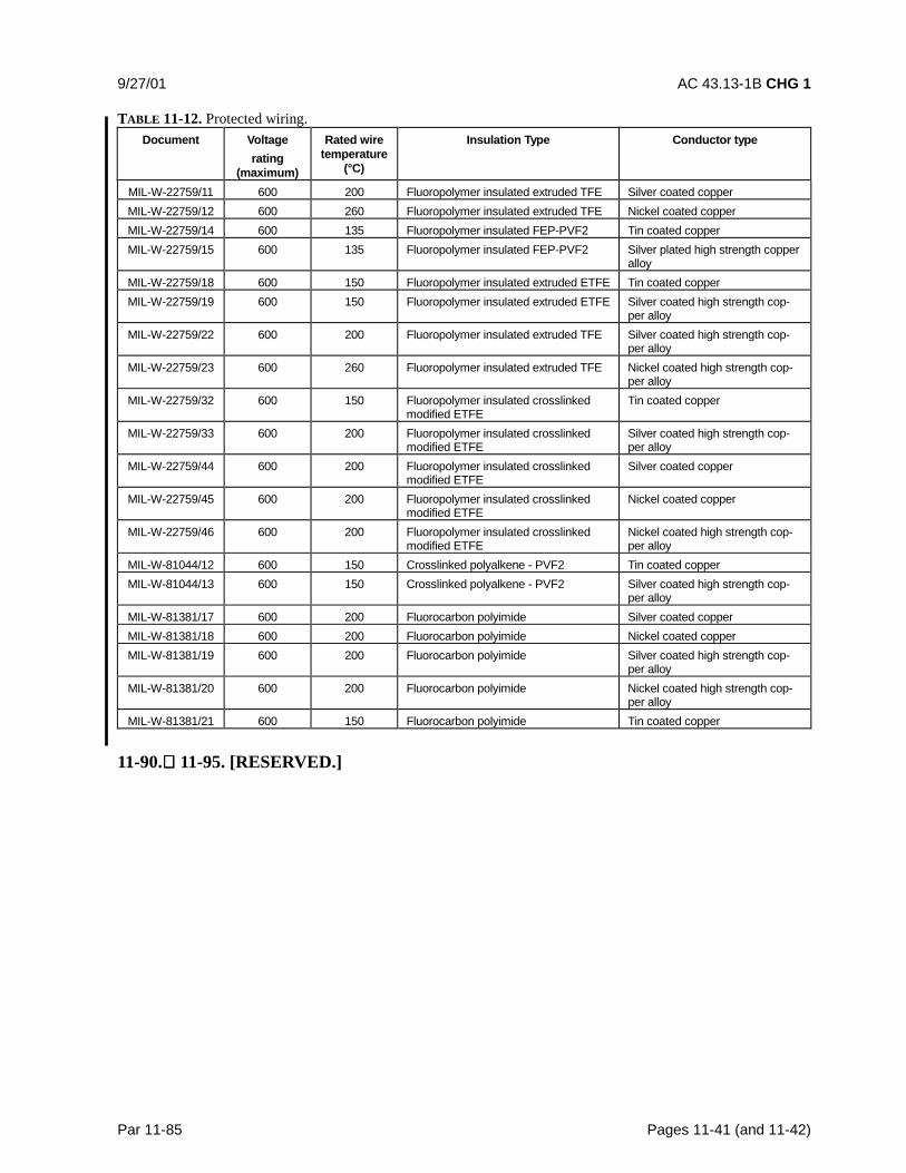
9/27/01 AC 43.13-1B CHG 1
Par 11-85 Pages 11-41 (and 11-42)
TABLE 11-12. Protected wiring.Document Voltage
rating(maximum)
Rated wiretemperature
(°C)
Insulation Type Conductor type
MIL-W-22759/11 600 200 Fluoropolymer insulated extruded TFE Silver coated copperMIL-W-22759/12 600 260 Fluoropolymer insulated extruded TFE Nickel coated copperMIL-W-22759/14 600 135 Fluoropolymer insulated FEP-PVF2 Tin coated copperMIL-W-22759/15 600 135 Fluoropolymer insulated FEP-PVF2 Silver plated high strength copper
alloyMIL-W-22759/18 600 150 Fluoropolymer insulated extruded ETFE Tin coated copperMIL-W-22759/19 600 150 Fluoropolymer insulated extruded ETFE Silver coated high strength cop-
per alloyMIL-W-22759/22 600 200 Fluoropolymer insulated extruded TFE Silver coated high strength cop-
per alloyMIL-W-22759/23 600 260 Fluoropolymer insulated extruded TFE Nickel coated high strength cop-
per alloyMIL-W-22759/32 600 150 Fluoropolymer insulated crosslinked
modified ETFETin coated copper
MIL-W-22759/33 600 200 Fluoropolymer insulated crosslinkedmodified ETFE
Silver coated high strength cop-per alloy
MIL-W-22759/44 600 200 Fluoropolymer insulated crosslinkedmodified ETFE
Silver coated copper
MIL-W-22759/45 600 200 Fluoropolymer insulated crosslinkedmodified ETFE
Nickel coated copper
MIL-W-22759/46 600 200 Fluoropolymer insulated crosslinkedmodified ETFE
Nickel coated high strength cop-per alloy
MIL-W-81044/12 600 150 Crosslinked polyalkene - PVF2 Tin coated copperMIL-W-81044/13 600 150 Crosslinked polyalkene - PVF2 Silver coated high strength cop-
per alloyMIL-W-81381/17 600 200 Fluorocarbon polyimide Silver coated copperMIL-W-81381/18 600 200 Fluorocarbon polyimide Nickel coated copperMIL-W-81381/19 600 200 Fluorocarbon polyimide Silver coated high strength cop-
per alloyMIL-W-81381/20 600 200 Fluorocarbon polyimide Nickel coated high strength cop-
per alloyMIL-W-81381/21 600 150 Fluorocarbon polyimide Tin coated copper
11-90. 11-95. [RESERVED.]

9/8/98 AC 43.13-1B
Par 11-96 Page 11-43
SECTION 8. WIRING INSTALLATION INSPECTION REQUIREMENTS
11-96. GENERAL. Wires and cablesshould be inspected for adequacy of support,protection, and general condition throughout.The desirable and undesirable features in air-craft wiring installations are listed below andindicate conditions that may or may not exist.Accordingly, aircraft wiring must be visuallyinspected for the following requirements:
CAUTION: For personal safety, andto avoid the possibility of fire, turn offall electrical power prior to startingan inspection of the aircraft electricalsystem or performing maintenance.
a. Wires and cables are supported bysuitable clamps, grommets, or other devices atintervals of not more than 24 inches, exceptwhen contained in troughs, ducts, or conduits.The supporting devices should be of a suitablesize and type, with the wires and cables heldsecurely in place without damage to the insu-lation.
b. Metal stand-offs must be used tomaintain clearance between wires and struc-ture. Employing tape or tubing is not accept-able as an alternative to stand-offs for main-taining clearance.
c. Phenolic blocks, plastic liners, orrubber grommets are installed in holes, bulk-heads, floors, or structural members where it isimpossible to install off-angle clamps tomaintain wiring separation. In such cases, ad-ditional protection in the form of plastic or in-sulating tape may be used.
d. Wires and cables in junction boxes,panels, and bundles are properly supported andlaced to provide proper grouping and routing.
e. Clamp retaining screws are properlysecured so that the movement of wires and ca-bles is restricted to the span between the pointsof support and not on soldered or mechanicalconnections at terminal posts or connectors.
f. Wire and cables are properly supportedand bound so that there is no interference withother wires, cables, and equipment.
g. Wires and cables are adequately sup-ported to prevent excessive movement in areasof high vibration.
h. Insulating tubing is secured by tying,tie straps or with clamps.
i. Continuous lacing (spaced 6 inchesapart) is not used, except in panels and junc-tion boxes where this practice is optional.When lacing is installed in this manner, out-side junction boxes should be removed and re-placed with individual loops.
j. Do not use tapes (such as friction orplastic tape) which will dry out in service, pro-duce chemical reactions with wire or cable in-sulation, or absorb moisture.
k. Insulating tubing must be kept at aminimum and must be used to protect wire andcable from abrasion, chafing, exposure tofluid, and other conditions which could affectthe cable insulation. However; the use of in-sulating tubing for support of wires and cablein lieu of stand-offs is prohibited.
l. Do not use moisture-absorbent materialas “fill” for clamps or adapters.
m. Ensure that wires and cables are nottied or fastened together in conduit or insulat-ing tubing.
AC 43.13-1B CHG 1 9/27/01
Page 11-44 Par 11-96
n. Ensure cable supports do not restrictthe wires or cables in such a manner as to in-terfere with operation of equipment shockmounts.
o. Do not use tape, tie straps, or cord forprimary support.
p. Make sure that drain holes are pres-ent in drip loops or in the lowest portion oftubing placed over the wiring.
q. Ensure that wires and cables arerouted in such a manner that chafing will notoccur against the airframe or other compo-nents.
r. Ensure that wires and cables are po-sitioned in such a manner that they are notlikely to be used as handholds or as support forpersonal belongings and equipment.
s. Ensure that wires and cables arerouted, insofar as practicable, so that they arenot exposed to damage by personnel movingwithin the aircraft.
t. Ensure that wires and cables are lo-cated so as not to be susceptible to damage bythe storage or shifting of cargo.
u. Ensure that wires and cables arerouted so that there is not a possibility of dam-age from battery electrolytes or other corrosivefluids.
v. Ensure that wires and cables are ade-quately protected in wheel wells and other ar-eas where they may be exposed to damagefrom impact of rocks, ice, mud, etc. (If re-routing of wires or cables is not practical, pro-tective jacketing may be installed). This typeof installation must be held to a minimum.
w. Where practical, route electrical wiresand cables above fluid lines and provide a 6inch separation from any flammable liquid,
fuel, or oxygen line, fuel tank wall, or otherlow voltage wiring that enters a fuel tank andrequires electrical isolation to prevent an igni-tion hazard. Where 6 inch spacing cannotpractically be provided, a minimum of 2 inchesmust be maintained between wiring and suchlines, related equipment, fuel tank walls andlow voltage wiring that enters a fuel tank.Such wiring should be closely clamped andrigidly supported and tied at intervals such thatcontact betwe4en such lines, related equip-ment, fuel tank walls or other wires, would notoccur, assuming a broken wire and a missingwire tie or clamp.
x. Ensure that a trap or drip loop isprovided to prevent fluids or condensed mois-ture from running into wires and cablesdressed downward to a connector, terminalblock, panel, or junction box.
y. Wires and cables installed in bilgesand other locations where fluids may betrapped are routed as far from the lowest pointas possible or otherwise provided with amoisture-proof covering.
z. Separate wires from high-temperatureequipment, such as resistors, exhaust stacks,heating ducts, etc., to prevent insulation break-down. Insulate wires that must run throughhot areas with a high-temperature insulationmaterial such as fiberglass or PTFE. Avoidhigh-temperature areas when using cableshaving soft plastic insulation such as polyeth-ylene, because these materials are subject todeterioration and deformation at elevated tem-peratures. Many coaxial cables have this typeof insulation.
aa. The minimum radius of bends inwire groups or bundles must not be less than10 times the outside diameter of the largestwire or cable, except that at the terminal stripswhere wires break out at terminations or re-
9/27/01 AC 43.13-1B CHG 1
Par 11-96 Page 11-45
verse direction in a bundle. Where the wire issuitably supported, the radius may be 3 timesthe diameter of the wire or cable. Where it isnot practical to install wiring or cables withinthe radius requirements, the bend should beenclosed in insulating tubing. The radius forthermocouple wire should be done in accor-dance with the manufacturer’s recommenda-tion and shall be sufficient to avoid excesslosses or damage to the cable.
bb. Ensure that RF cables, e.g., coaxialand triaxial are bent at a radius of no less than6 times the outside diameter of the cable.
cc. Ensure that wires and cables, thatare attached to assemblies where relativemovement occurs (such as at hinges and ro-tating pieces; particularly doors, control sticks,control wheels, columns, and flight controlsurfaces), are installed or protected in such amanner as to prevent deterioration of the wiresand cables caused by the relative movement ofthe assembled parts.
dd. Ensure that wires and electrical ca-bles are separated from mechanical control ca-bles. In no instance should wire be able tocome closer than 1/2 inch to such controlswhen light hand pressure is applied to wires orcontrols. In cases where clearance is less thanthis, adequate support must be provided toprevent chafing.
ee. Ensure that wires and cables areprovided with enough slack to meet the fol-lowing requirements:
(1) Permit ease of maintenance.
(2) Prevent mechanical strain on thewires, cables, junctions, and supports.
(3) Permit free movement of shock andvibration mounted equipment.
(4) Allow shifting of equipment, asnecessary, to perform alignment, servicing,tuning, removal of dust covers, and changingof internal components while installed in air-craft.
ff. Ensure that unused wires are indi-vidually dead-ended, tied into a bundle, andsecured to a permanent structure. Each wireshould have strands cut even with the insula-tion and a pre-insulated closed end connectoror a 1-inch piece of insulating tubing placedover the wire with its end folded back and tied.
gg. Ensure that all wires and cables areidentified properly at intervals of not morethan 15 inches. Coaxial cables are identified atboth equipment ends.
11-97. WIRING REPLACEMENT. Wir-ing must be replaced with equivalent wire (seeparagraph 11-78) when found to have any ofthe following defects:
a. Wiring that has been subjected tochafing or fraying, that has been severely dam-aged, or that primary insulation is suspected ofbeing penetrated.
b. Wiring on which the outer insulation isbrittle to the point that slight flexing causes itto crack.
c. Wiring having weather-cracked outerinsulation.
d. Wiring that is known to have been ex-posed to electrolyte or on which the insulationappears to be, or is suspected of being, in aninitial stage of deterioration due to the effectsof electrolyte.

AC 43.13-1B CHG 1 9/27/01
Page 11-46 Par 11-97
e. Check wiring that shows evidence ofoverheating (even if only to a minor degree)for the cause of the overheating.
f. Wiring on which the insulation has be-come saturated with engine oil, hydraulic fluid,or another lubricant.
g. Wiring that bears evidence of havingbeen crushed or severely kinked.
h. Shielded wiring on which the metallicshield is frayed and/or corroded. Cleaningagents or preservatives should not be used tominimize the effects of corrosion or deteriora-tion of wire shields.
i. Wiring showing evidence of breaks,cracks, dirt, or moisture in the plastic sleevesplaced over wire splices or terminal lugs.
j. Sections of wire in which splices occurat less than 10-foot intervals, unless specifi-cally authorized, due to parallel connections,locations, or inaccessibility.
k. When replacing wiring or coaxial ca-bles, identify them properly at both equipmentand power source ends.
l. Wire substitution-In the repair andmodification of existing aircraft, when a re-placement wire is required, the maintenancemanual for that aircraft should first be re-viewed to determine if the original aircraftmanufacturer (OAM) has approved any sub-stitution. If not, then the OAM should becontacted for an acceptable replacement.
m. Testing of the electrical and chemi-cal integrity of the insulation of sample wirestaken from areas of the aircraft that have expe-rienced wiring problems in the past, can beused to supplement visual examination of thewire. The test for chemical integrity should be
specific for the degradation mode of the insu-lation. If the samples fail either the electricalor chemical integrity tests, then the wiring inthe area surrounding the sampling area is acandidate for replacement.
11-98. TERMINALS AND TERMINALBLOCKS. Inspect to ensure that the follow-ing installation requirements are met:
a. Insulating tubing is placed over termi-nals (except pre-insulated types) to provideelectrical protection and mechanical supportand is secured to prevent slippage of the tubingfrom the terminal.
b. Terminal module blocks are securelymounted and provided with adequate electricalclearances or insulation strips betweenmounting hardware and conductive parts, ex-cept when the terminal block is used forgrounding purposes.
c. Terminal connections to terminalmodule block studs and nuts on unused studsare tight.
d. Evidence of overheating and corro-sion is not present on connections to terminalmodule block studs.
e. Physical damage to studs, stud threads,and terminal module blocks is not evident.Replace cracked terminal strips and thosestuds with stripped threads.
f. The number of terminal connectionsto a terminal block stud does not exceed four,unless specifically authorized.
g. Shielding should be dead-ended withsuitable insulated terminals.
h. All wires, terminal blocks, and indi-vidual studs are clearly identified to corre-spond to aircraft wiring manuals.
9/27/01 AC 43.13-1B CHG 1
Par 11-98 Page 11-47
i. Terminations should be made usingterminals of the proper size and the appropriateterminal crimping tools.
11-99. FUSES AND FUSE HOLDERS.Inspect as follows:
a. Check security of connections to fuseholders.
b. Inspect for the presence of corrosionand evidence of overheating on fuses and fuseholders. Replace corroded fuses and cleanfuse holders. If evidence of overheating isfound, check for correct rating of fuse.
c. Check mounting security of fuseholder.
d. Inspect for replenishment of sparefuses used in flight. Replace with fuses of ap-propriate current rating only.
e. Inspect for exposed fuses susceptibleto shorting. Install cover of nonconductingmaterial if required.
11-100. CONNECTORS. Ensure reliabilityof connectors by verifying that the followingconditions are met or that repairs are effectedas required.
a. Inspect connectors for security andevidence of overheating (cause of over-heatingmust be corrected), and exteriors for corrosionand cracks. Also, wires leading to connectorsmust be inspected for deterioration due tooverheating. Replace corroded connectionsand overheated connectors.
b. Ensure installation of cable clamp(reference MIL-C-85049) adapters on applica-ble MS connectors, except those that aremoisture-proof.
c. See that silicone tape is wrappedaround wires in MS3057 cable clamp adapters
so that tightening of the cable clamp adaptercap provides sufficient grip on the wires tokeep tension from being applied to the con-nector pins.
d. Make sure unused plugs and recep-tacles are covered to prevent inclusion of dustand moisture. Receptacles should have metalor composite dust caps attached by their nor-mal mating method. Plugs may have a dustcap similar to above or have a piece ofpolyolefin shrink sleeving shrunk over theconnector, starting from the backshell threads,with a tail sufficiently long enough to double-back over the connector and be tied with poly-ester lacing tape behind the coupling nut. Thecable identification label should be visible be-hind the connector or a tag should be attachedidentifying the associated circuit or attachingequipment. The connector should be attachedto structure by its normal mounting means orby the use of appropriate clamps.
e. Ensure that connectors are fully matedby checking position and tightness of couplingring or its alignment with fully mated indicatorline on receptacle, if applicable.
f. Ensure that the coupling nut of MSconnectors is safetied, by wire or other me-chanical locking means, as required by appli-cable aircraft instructional manuals.
g. Ensure that moisture-absorbent ma-terial is not used as “fill” for MS3057 clampsor adapters.
h. Ensure that there is no evidence ofdeterioration such as cracking, missing, ordisintegration of the potting material.
i. Identical connectors in adjacent loca-tions can lead to incorrect connections. Whensuch installations are unavoidable, the attached
AC 43.13-1B CHG 1 9/27/01
Page 11-48 Par 11-100
wiring must be clearly identified and must berouted and clamped so that it cannot be mis-matched.
j. Connectors in unpressurized areasshould be positioned so that moisture willdrain out of them when unmated. Wires exit-ing connectors must be routed so that moisturedrains away from them.
11-101. JUNCTION BOXES, PANELS,SHIELDS, AND MICROSWITCH HOUS-INGS. Examine housing assemblies to ascer-tain the following:
a. Verify that one or more suitableholes, about 3/8-inch diameter, but not lessthan 1/8-inch diameter, are provided at thelowest point of the box, except vapor-tightboxes, to allow for drainage with the aircrafton the ground or in level flight.
b. Verify that vapor tight or explosionproof boxes are externally labeled VAPOR-TIGHT or EXPLOSION PROOF.
c. Verify that boxes are securelymounted.
d. Verify that boxes are clean internallyand free of foreign objects.
e. Verify that safety wiring is installedon all lid fasteners on J-boxes, panels, shields,or microswitch housings which are installed inareas not accessible for inspection in flight,unless the fasteners incorporate self-lockingdevices.
f. Verify that box wiring is properlyaligned.
g. Verify that there are no unplugged, un-used holes (except drainage holes) in boxes.
11-102. CONDUIT - RIGID METALLIC,
FLEXIBLE METALLIC AND RIGIDNONMETALLIC. Inspection of conduit as-semblies should ascertain that:
a. Conduit is relieved of strain and flex-ing of ferrules.
b. Conduit is not collapsed or flattenedfrom excessive bending.
c. Conduits will not trap fluids or con-densed moisture. Suitable drain holes shouldbe provided at the low points.
d. Bonding clamps do not cause damageto the conduit.
e. Weatherproof shields on flexible con-duits of the nose and main landing gear and inwheel wells are not broken; that metallic braidof weatherproof conduit is not exposed; andthat conduit nuts, ferrules, and conduit fittingsare installed securely.
f. Ends of open conduits are flared orrouted to avoid sharp edges that could chafewires exiting from the conduit.
11-103. JUNCTIONS. Ensure that only air-craft manufacturer approved devices, such assolderless type terminals, terminal blocks,connectors, disconnect splices, permanentsplices, and feed-through bushings are used forcable junctions. Inspect for the provisionsoutlined below:
a. Electrical junctions should be pro-tected from short circuits resulting frommovement of personnel, cargo, cases, andother loose or stored materials. Protectionshould be provided by covering the junction,installing them in junction boxes, or by locat-ing them in such a manner that additional pro-tection is not required, etc.

9/27/01 AC 43.13-1B CHG 1
Par 11-103 Page 11-49
b. Exposed junctions and buses shouldbe protected with insulating materials. Junc-tions and buses located within enclosed areascontaining only electrical and electronicequipment are not considered as exposed.
c. Electrical junctions should be me-chanically and electrically secure. They shouldnot be subject to mechanical strain or used as asupport for insulating materials, except for in-sulation on terminals.
11-104. CIRCUIT BREAKERS. Notethose circuit breakers which have a tendency toopen circuits frequently, require resetting morethan normal, or are subject to nuisance trip-ping. Before considering their replacement,investigate the reason.
11-105. SYSTEM SEPARATION. Wiresof redundant aircraft systems should be routedin separate bundles and through separate con-nectors to prevent a single fault from disablingmultiple systems. Wires not protected by acircuit-protective device, such as a circuitbreaker or fuse, should be routed separatelyfrom all other wiring. Power feeders fromseparate sources should be routed in separatebundles from each other and from other air-craft wiring, in order to prevent a single faultfrom disabling more than one power source.The ground wires from aircraft power sourcesshould be attached to the airframe at separatepoints so that a single failure will not disablemultiple sources. Wiring that is part of elec-tro-explosive subsystems, such as cartridge-actuated fire extinguishers, rescue hoist shear,and emergency jettison devices, should berouted in shielded and jacketed twisted-paircables, shielded without discontinuities, andkept separate from other wiring at connectors.To facilitate identification of specific separatedsystem bundles, use of colored plastic cableties or lacing tape is allowed. During aircraftmaintenance, colored plastic cable straps orlacing tape should be replaced with the sametype and color of tying materials.
11-106. ELECTROMAGNETIC INTER-FERENCE (EMI). Wiring of sensitive cir-cuits that may be affected by EMI must berouted away from other wiring interference, orprovided with sufficient shielding to avoidsystem malfunctions under operating condi-tions. EMI between susceptible wiring andwiring which is a source of EMI increases inproportion to the length of parallel runs anddecreases with greater separation. EMI shouldbe limited to negligible levels in wiring relatedto critical systems, that is, the function of thecritical system should not be affected by theEMI generated by the adjacent wire. Use ofshielding with 85 percent coverage or greateris recommended. Coaxial, triaxial, twinaxial,or quadraxial cables should be used, whereverappropriate, with their shields connected toground at a single point or multiple points, de-pending upon the purpose of the shielding.The airframe grounded structure may also beused as an EMI shield.
11-107. INTERFERENCE TESTS. Per-form an interference test for installed equip-ment and electrical connections as follow:
a. The equipment must be installed in ac-cordance with manufacturer’s installation in-structions. Visually inspect all the installedequipment to determine that industry standardworkmanship and engineering practices wereused. Verify that all mechanical and electricalconnections have been properly made and thatthe equipment has been located and installed inaccordance with the manufacturer’s recom-mendations. The wire insulation temperaturerating should also be considered.
b. Power input tests must be conductedwith the equipment powered by the airplane’selectrical power generating system, unless oth-erwise specified.

AC 43.13-1B CHG 1 9/27/01
Page 11-50 Par 11-107
c. All associated electrically operatedequipment and systems on the airplane mustbe on and operating before conducting inter-ference tests, unless otherwise specified.
d. The effects on interference must beevaluated as follows:
(1) The equipment shall not be thesource of harmful conducted or radiated inter-ference or adversely affect other equipment orsystems installed in the airplane.
(2) With the equipment energized onthe ground, individually operate other electri-cally operated equipment and systems on theairplane to determine that no significant con-ducted or radiated interference exists. Evalu-ate all reasonable combinations of control set-tings and operating modes. Operate communi-cation and navigation equipment on at leastone low, high and mid-band frequency. Makenote of systems or modes of operation thatshould also be evaluated during flight.
(3) For airplane equipment and systemsthat can be checked only in flight, determinethat no operationally significant conducted orradiated interference exists. Evaluate all rea-sonable combinations of control settings andoperating modes. Operate communicationsand navigation equipment on at least one low,high and mid-band frequency.
NOTE: Electromagnetic compatibil-ity problems which develop after in-stallation of this equipment may resultfrom such factors as design charac-teristics of previously installed systemsor equipment, and the physical in-stallation itself. It is not intended that
the equipment manufacturer shoulddesign for all installation environ-ments. The installing facility will beresponsible for resolving any incom-patibility between this equipment andpreviously installed equipment in theairplane. The various factors con-tributing to the incompatibility shouldbe considered.
NOTE: Ground EMI test have consis-tently been found adequate for fol-low-on approvals of like or identicalequipment types, irrespective of theairplane model used for the initial ap-proval. Radio frequency transmissiondevices, such as wireless telephones,must also be tested with respect totheir transmission frequencies andharmonics.
11-108. IDENTIFICATION STENCILSAND PLACARDS ON ELECTRICALEQUIPMENT. Replace worn stencils andmissing placards.
11-109. 11-114. [RESERVED.]
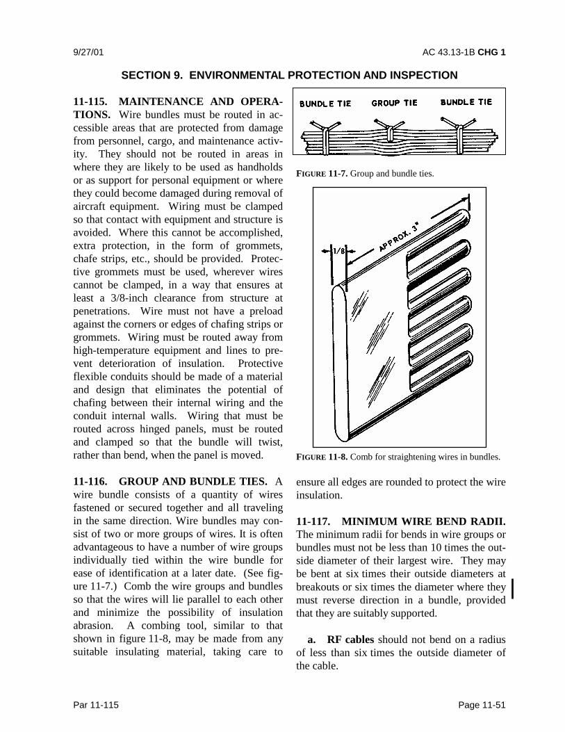
9/27/01 AC 43.13-1B CHG 1
Par 11-115 Page 11-51
SECTION 9. ENVIRONMENTAL PROTECTION AND INSPECTION
11-115. MAINTENANCE AND OPERA-TIONS. Wire bundles must be routed in ac-cessible areas that are protected from damagefrom personnel, cargo, and maintenance activ-ity. They should not be routed in areas inwhere they are likely to be used as handholdsor as support for personal equipment or wherethey could become damaged during removal ofaircraft equipment. Wiring must be clampedso that contact with equipment and structure isavoided. Where this cannot be accomplished,extra protection, in the form of grommets,chafe strips, etc., should be provided. Protec-tive grommets must be used, wherever wirescannot be clamped, in a way that ensures atleast a 3/8-inch clearance from structure atpenetrations. Wire must not have a preloadagainst the corners or edges of chafing strips orgrommets. Wiring must be routed away fromhigh-temperature equipment and lines to pre-vent deterioration of insulation. Protectiveflexible conduits should be made of a materialand design that eliminates the potential ofchafing between their internal wiring and theconduit internal walls. Wiring that must berouted across hinged panels, must be routedand clamped so that the bundle will twist,rather than bend, when the panel is moved.
11-116. GROUP AND BUNDLE TIES. Awire bundle consists of a quantity of wiresfastened or secured together and all travelingin the same direction. Wire bundles may con-sist of two or more groups of wires. It is oftenadvantageous to have a number of wire groupsindividually tied within the wire bundle forease of identification at a later date. (See fig-ure 11-7.) Comb the wire groups and bundlesso that the wires will lie parallel to each otherand minimize the possibility of insulationabrasion. A combing tool, similar to thatshown in figure 11-8, may be made from anysuitable insulating material, taking care to
FIGURE 11-7. Group and bundle ties.
FIGURE 11-8. Comb for straightening wires in bundles.
ensure all edges are rounded to protect the wireinsulation.
11-117. MINIMUM WIRE BEND RADII.The minimum radii for bends in wire groups orbundles must not be less than 10 times the out-side diameter of their largest wire. They maybe bent at six times their outside diameters atbreakouts or six times the diameter where theymust reverse direction in a bundle, providedthat they are suitably supported.
a. RF cables should not bend on a radiusof less than six times the outside diameter ofthe cable.

AC 43.13-1B CHG 1 9/27/01
Page 11-52 Par 11-117
b. Care should be taken to avoid sharpbends in wires that have been marked with thehot stamping process.
11-118. SLACK. Wiring should be installedwith sufficient slack so that bundles and indi-vidual wires are not under tension. Wires con-nected to movable or shock-mounted equip-ment should have sufficient length to allowfull travel without tension on the bundle.Wiring at terminal lugs or connectors shouldhave sufficient slack to allow two retermina-tions without replacement of wires. This slackshould be in addition to the drip loop and theallowance for movable equipment. Normally,wire groups or bundles should not exceed1/2-inch deflection between support points, asshown in figure 11-9a. This measurement maybe exceeded provided there is no possibility ofthe wire group or bundle touching a surfacethat may cause abrasion. Sufficient slackshould be provided at each end to:
a. Permit replacement of terminals.
b. Prevent mechanical strain on wires.
c. Permit shifting of equipment for main-tenance purposes.
11-118A. DRIP LOOP IN WIRE BUNDLE.A drip loop is an area where wire is dresseddownward to a connector, terminal block,panel, or junction bo. In additional to theservice termination and strain relief, a trap ordrip loop shall be provided in the wiring toprevent fluid or condensate from running intothe above devices. (see Figure 11-9b) Wiresor groups of wires should enter a junction boxor piece of equipment in an upward directionwhere practicable. Where wires must berouted downwards to a junction box or unit ofelectric equipment, the entry should be sealedor adequate slack should be provided to form atrap or drip loop to prevent liquid fromrunning down the wires in the box or electricunit.
11-119. POWER FEEDERS. The powerfeeder wires should be routed so that they canbe easily inspected or replaced. They must begiven special protection to prevent potentialchafing against other wiring, aircraft structure,or components.
11-120. RF CABLE. All wiring needs to beprotected from damage. However, coaxial andtriaxial cables are particularly vulnerable tocertain types of damage. Personnel should ex-ercise care while handling or working aroundcoaxial. Coaxial damage can occur whenclamped too tightly, or when they are bentsharply (normally at or near connectors).Damage can also be incurred during unrelatedmaintenance actions around the coaxial cable.Coaxial can be severely damaged on the insidewithout any evidence of damage on the out-side. Coaxial cables with solid center con-ductors should not be used. Stranded centercoaxial cables can be used as a direct replace-ment for solid center coaxial.
11-121. PRECAUTIONS.
a. Never kink coaxial cable.
b. Never drop anything on coaxial cable.
c. Never step on coaxial cable.
d. Never bend coaxial cable sharply.
e. Never loop coaxial cable tighter thanthe allowable bend radius.
f. Never pull on coaxial cable except in astraight line.
g. Never use coaxial cable for a handle,lean on it, or hang things on it (or any otherwire).
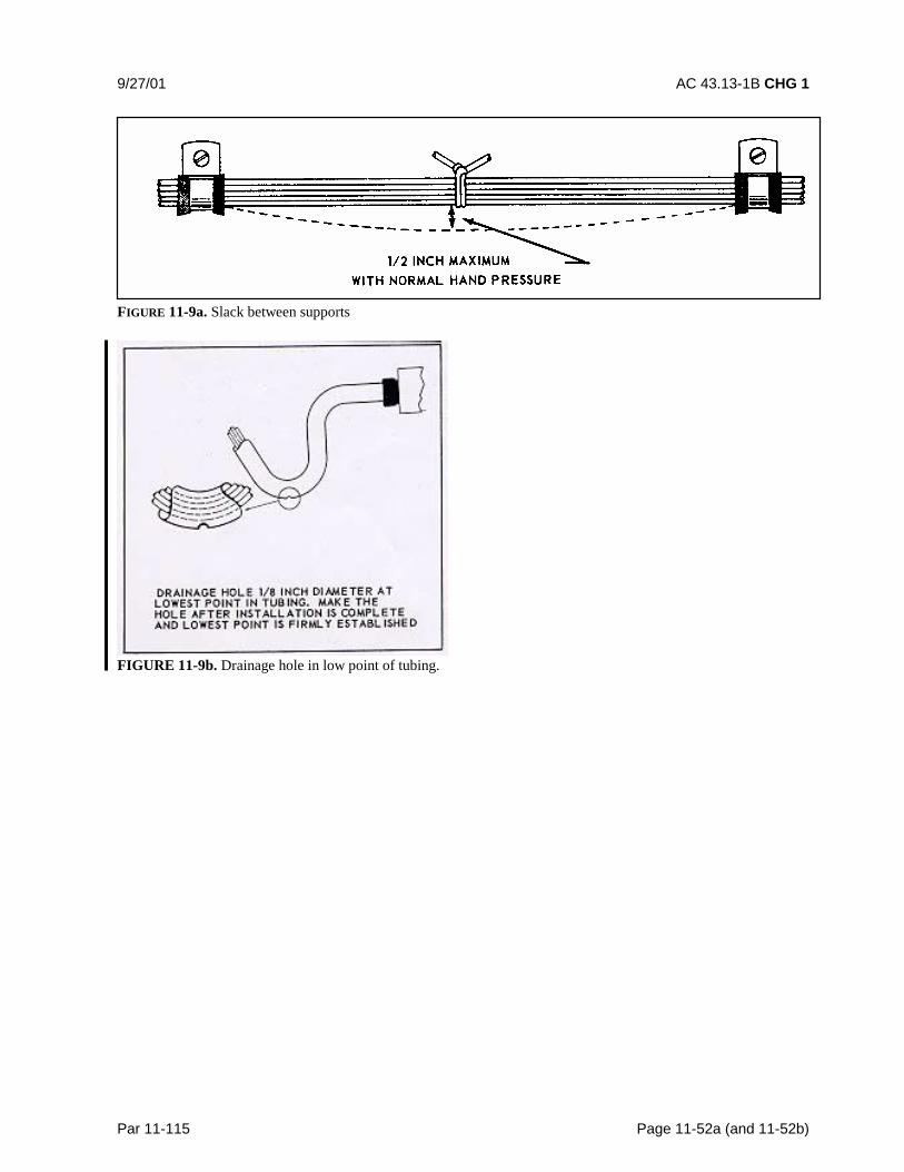
9/27/01 AC 43.13-1B CHG 1
Par 11-115 Page 11-52a (and 11-52b)
FIGURE 11-9a. Slack between supports
FIGURE 11-9b. Drainage hole in low point of tubing.

9/8/98 AC 43.13-1B
Par 11-115 Page 11-53
11-122. MOISTURE PROTECTION,WHEEL WELLS, AND LANDING GEARAREAS.
a. Wires located on landing gear and inthe wheel well area can be exposed to manyhazardous conditions if not suitably protected.Where wire bundles pass flex points, theremust not be any strain on attachments or ex-cessive slack when parts are fully extended orretracted. The wiring and protective tubingmust be inspected frequently and replaced atthe first sign of wear.
b. Wires should be routed so that fluidsdrain away from the connectors. When this isnot practicable, connectors must be potted.Wiring which must be routed in wheel wells orother external areas must be given extra pro-tection in the form of harness jacketing andconnector strain relief. Conduits or flexiblesleeving used to protect wiring must beequipped with drain holes to prevent entrap-ment of moisture.
11-123. PROTECTION AGAINST PER-SONNEL AND CARGO. Wiring must be in-stalled so the structure affords protectionagainst its use as a handhold and damage fromcargo. Where the structure does not affordadequate protection, conduit must be used, or asuitable mechanical guard must be provided.
11-124. HEAT PRECAUTIONS. Wiringmust be routed away from high-temperatureequipment and lines to prevent deterioration ofinsulation. Wires must be rated (referenceparagraph 11-66 and 11-67) so that the con-ductor temperature remains within the wirespecification maximum when the ambienttemperature, and heat rise, related to currentcarrying capacity are taken into account. Theresidual heating effects caused by exposure to
sunlight when aircraft are parked for extendedperiods should also be taken into account.Wires such as in fire detection, fire extin-guishing, fuel shutoff, and fly-by-wire flightcontrol systems that must operate during andafter a fire, must be selected from types thatare qualified to provide circuit integrity afterexposure to fire for a specified period. Wireinsulation deteriorates rapidly when subjectedto high temperatures. Do not use wire withsoft polyethylene insulation in areas subject tohigh temperatures. Use only wires or cableswith heat resistance shielding or insulation.
11-125. MOVABLE CONTROLS WIR-ING PRECAUTIONS. Clamping of wiresrouted near movable flight controls must beattached with steel hardware and must bespaced so that failure of a single attachmentpoint can not result in interference with con-trols. The minimum separation between wir-ing and movable controls must be at least1/2 inch when the bundle is displaced by lighthand pressure in the direction of the controls.
11-126. FLAMMABLE FLUIDS ANDGASES. An arcing fault between an electricalwire and a metallic flammable fluid line maypuncture the line and result in a fire. Every ef-fort must be made to avoid this hazard byphysical separation of the wire from lines andequipment containing oxygen, oil, fuel, hy-draulic fluid, or alcohol. Wiring must berouted above these lines and equipment with aminimum separation of 6 inches or morewhenever possible. When such an arrange-ment is not practicable, wiring must be routedso that it does not run parallel to the fluidlines. A minimum of 2 inches must be main-tained between wiring and such lines andequipment, except when the wiring is posi-tively clamped to maintain at least 1/2-inchseparation, or when it must be connected

AC 43.13-1B 9/8/98
Page 11-54 Par 11-126
directly to the fluid-carrying equipment. In-stall clamps as shown in figure 11-10. Theseclamps should not be used as a means of sup-porting the wire bundle. Additional clampsshould be installed to support the wire bundleand the clamps fastened to the same structureused to support the fluid line(s) to preventrelative motion.
FIGURE 11-10. Separation of wires from plumbing lines.
11-127. 11-134. [RESERVED.]

9/8/98 AC 43.13-1B
Par 11-135 Page 11-55
SECTION 10. SERVICE LOOP HARNESSES (Plastic Tie Strips)
11-135. GENERAL. The primary functionof a service loop harness is to provide ease ofmaintenance. The components, mounted inthe instrument panel and on the lower consoleand other equipment that must be moved toaccess electrical connectors, are connected toaircraft wiring through service loops. Chafingin service loop harnesses is controlled usingthe following techniques.
11-136. SUPPORT. Only string ties orplastic cable straps in accordance with para-graph 11-158 should be used on service loopharnesses. A 90° or “Y” type spot tie shouldbe installed at the harness breakout point onthe harness bundle. Ties should be installedon service loop harnesses at 4 to 6-inch inter-vals.
11-137. ANTI-CHAFING MATERIAL.When service loops are likely to be in contactwith each other, expandable sleeving orequivalent chafe protection jacket materialmust be installed over service loop harnessesto prevent harness-to-harness chafing. Thesleeve should be held in place with string tiesat 6 to 8-inch intervals. Harness identificationlabels should be installed, with string tie,within 3 inches of the service loop harness in-stallation.
11-138. STRAIN RELIEF. The strain re-lief components may be installed to controlrouting where close clearance exists betweentermination and other components or bulk-heads. Strain relief components provide sup-port of the service loop harness at the termina-tion point. Connector strain relief adapters,
heat-shrinkable boot, or a length of heat-shrinkable tubing should be installed. Theheat-shrinkable boots will provide preselectedangles of wire harness termination when heatis applied. Heat-shrinkable tubing should beheld at the desired angle until cool.
11-139. “SERVICE LOOP.” Primary sup-port for service loop harness(es) should be acushion clamp and a connector at the harnesstermination. Service loop harnesses should beinspected for the following:
a. Adequate Length. Componentsshould extend out from their mounting posi-tion a distance that permits rotating and un-locking (or locking) the electrical connector.Usually a distance of 3 to 6 inches, with allother components installed, should be suffi-cient.
b. Bundle BreakOut Point.
(1) Bundle breakout point should beadequately supported with string tie.
(2) Service loop must maintain a mini-mum bend radius of 3 times the harness di-ameter.
(3) The breakout point should be lo-cated directly behind, beside, below, or abovethe component so that the service loop harnessdoes not bind other components.
(4) Plastic ties should not be used be-tween the service loop breakout and the elec-trical connector when they are likely to chafeagainst adjacent wire.
AC 43.13-1B 9/8/98
Page 11-56 Par 11-139
c. Service Loop Routing. The serviceloop harness should be routed directly from thebreakout point to the component. The harnessshould not contact moving mechanical compo-nents or linkage, and should not be wrapped ortangled with other service loop harnesses.
d. Service Loop Harness Termination.Strain relief should be provided at the serviceloop harness termination, and is normally pro-vided by the connector manufacturer’s back-shell, heat-shrinkable boot, or tubing.
11-140. 11-145. [RESERVED.]
9/27/01 AC 43.13-1B CHG 1
Par 11-146 Page 11-57
SECTION 11. CLAMPING
11-146. GENERAL. Wires and wire bun-dles must be supported by using clamps meet-ing Specification MS-21919, or plastic cablestraps in accessible areas if correctly appliedwithin the restrictions of paragraph 11-158.Clamps and other primary support devicesmust be constructed of materials that are com-patible with their installation and environment,in terms of temperature, fluid resistance, expo-sure to ultraviolet (UV) light, and wire bundlemechanical loads. They should be spaced atintervals not exceeding 24 inches. Clamps onwire bundles should be selected so that theyhave a snug fit without pinching wires, asshown in figure 11-11 through figure 11-13.
CAUTION: The use of metal clampson coaxial RF cables may cause prob-lems if clamp fit is such that RF ca-ble’s original cross-section is distorted.
a. Clamps on wire bundles should notallow the bundle to move through the clampwhen a slight axial pull is applied. Clamps onRF cables must fit without crushing and mustbe snug enough to prevent the cable frommoving freely through the clamp, but may al-low the cable to slide through the clamp whena light axial pull is applied. The cable or wirebundle may be wrapped with one or more turnsof electrical tape when required to achieve thisfit. Plastic clamps or cable ties must not beused where their failure could result in inter-ference with movable controls, wire bundlecontact with movable equipment, or chafingdamage to essential or unprotected wiring.They must not be used on vertical runs whereinadvertent slack migration could result inchafing or other damage. Clamps must be in-stalled with their attachment hardware posi-tioned above them, wherever practicable, sothat they are unlikely to rotate as the result ofwire bundle weight or wire bundle chafing.(See figure 11-11.).
b. Clamps lined with nonmetallic mate-rial should be used to support the wire bundlealong the run. Tying may be used betweenclamps, but should not be considered as a sub-stitute for adequate clamping. Adhesive tapesare subject to age deterioration and, therefore,are not acceptable as a clamping means.
c. The back of the clamp, wheneverpractical, should be rested against a structuralmember. Stand-offs should be used to main-tain clearance between the wires and thestructure. Clamps must be installed in such amanner that the electrical wires do not come incontact with other parts of the aircraft whensubjected to vibration. Sufficient slack shouldbe left between the last clamp and the electri-cal equipment to prevent strain at the terminaland to minimize adverse effects on shock-mounted equipment. Where wires or wirebundles pass through bulkheads or otherstructural members, a grommet or suitableclamp should be provided to prevent abrasion.
d. When wire bundle is clamped intoposition, if there is less than 3/8-inch clearancebetween the bulkhead cutout and the wire bun-dle, a suitable grommet should be installed asindicated in figure 11-14. The grommet maybe cut at a 45 degree angle to facilitate instal-lation, provided it is cemented in place and theslot is located at the top of the cutout.
11-147. WIRE AND CABLE CLAMPSINSPECTION. Inspect wire and cableclamps for proper tightness. Where cablespass through structure or bulkheads, inspectfor proper clamping and grommets. Inspectfor sufficient slack between the last clamp andthe electronic equipment to prevent strain atthe cable terminals and to minimize adverseeffects on shock-mounted equipment.

AC 43.13-1B CHG 1 9/27/01
Page 11-58 Par 11-49
FIGURE 11-11. Safe angle for cable clamps.
FIGURE 11-12. Typical mounting hardware for MS-21919 cable clamps.
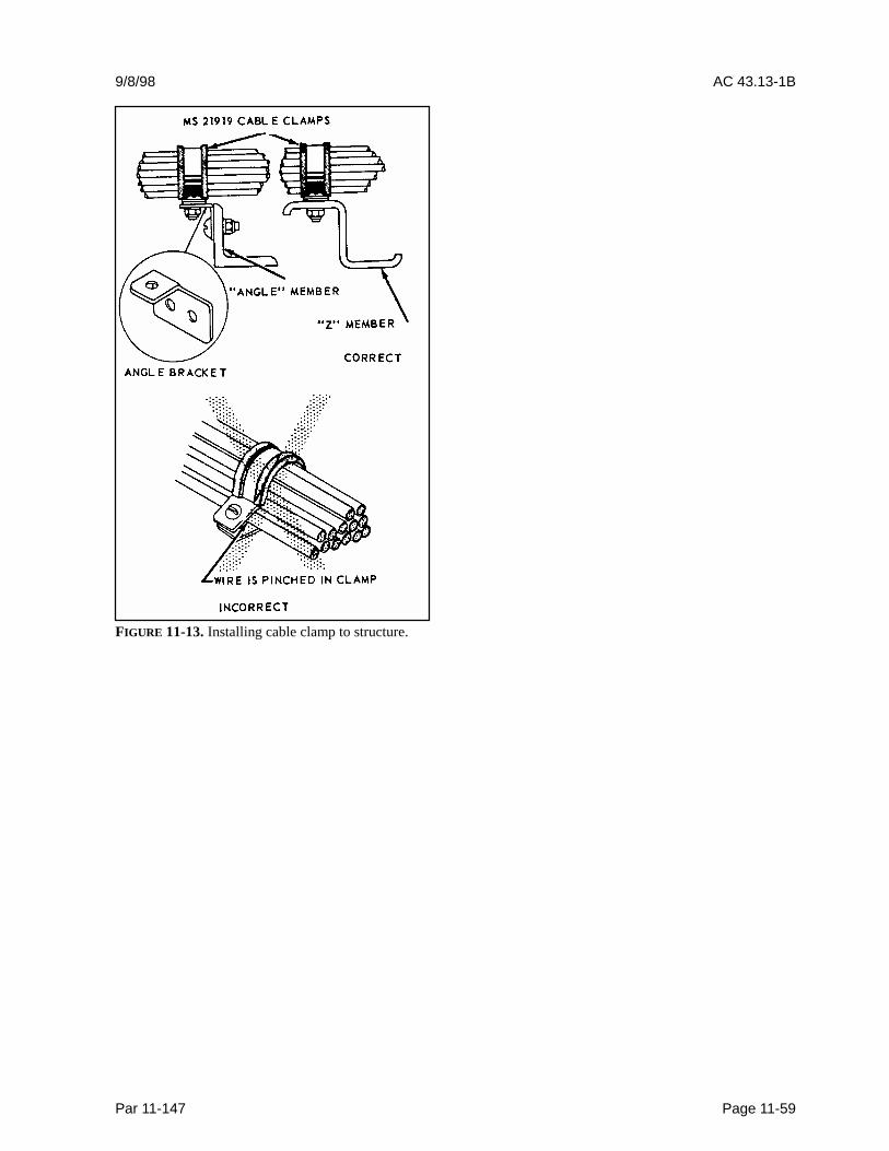
9/8/98 AC 43.13-1B
Par 11-147 Page 11-59
FIGURE 11-13. Installing cable clamp to structure.

AC 43.13-1B 9/8/98
Page 11-60 Par 11-147
FIGURE 11-14. Clamping at a bulkhead hole.
11-148. 11-154. [RESERVED.]
9/8/98 AC 43.13-1B
Par 11-155 Page 11-61
SECTION 12. WIRE INSULATION AND LACING STRING TIE
11-155. GENERAL. Insulation of wiresshould be appropriately chosen in accordancewith the environmental characteristics of wirerouting areas. Routing of wires with dissimilarinsulation, within the same bundle, is not rec-ommended, particularly when relative motionand abrasion between wires having dissimilarinsulation can occur. Soft insulating tubing(spaghetti) cannot be considered as mechanicalprotection against external abrasion of wire;since at best, it provides only a delaying ac-tion. Conduit or ducting should be used whenmechanical protection is needed.
11-156. INSULATION MATERIALS. In-sulating materials should be selected for thebest combination of characteristics in the fol-lowing categories:
a. Abrasion resistance.
b. Arc resistance (noncarbon tracking).
c. Corrosion resistance.
d. Cut-through strength.
e. Dielectric strength.
f. Flame resistance.
g. Heat distortion temperature.
h. Impact strength.
i. Mechanical strength.
j. Resistance to fluids.
k. Resistance to notch propagation.
l. Smoke emission.
m. Special properties unique to theaircraft.
n. For a more complete selection of in-sulated wires refer to SAE AS 4372 AerospaceWire Performance Requirement and SAEAS 4373 Test Methods for Aerospace Wire.
11-157. STRIPPING INSULATION.Attachment of wire, to connectors or termi-nals, requires the removal of insulation to ex-pose the conductors. This practice is com-monly known as stripping. Stripping may beaccomplished in many ways; however, thefollowing basic principles should be practiced.
a. Make sure all cutting tools used forstripping are sharp.
b. When using special wire strippingtools, adjust the tool to avoid nicking, cutting,or otherwise damaging the strands.
c. Damage to wires should not exceed thelimits specified in table 11-13.
d. When performing the stripping op-eration, remove no more insulation than isnecessary.
11-158. LACING AND TIES. Ties, lacing,and straps are used to secure wire groups orbundles to provide ease of maintenance, in-spection, and installation. Braided lacing tapeper MIL-T-43435 is suitable for lacing andtying wires. In lieu of applying ties, strapsmeeting Specification MS17821 or MS17822may be used in areas where the temperaturedoes not exceed 120 �C. Straps may not beused in areas of SWAMP such as wheel wells,near wing flaps or wing folds. They may notbe used in high vibration areas, where failure
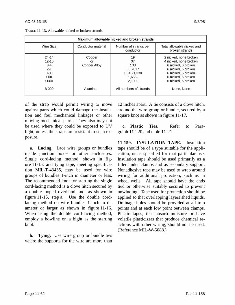
AC 43.13-1B 9/8/98
Page 11-62 Par 11-158
TABLE 11-13. Allowable nicked or broken strands.
Maximum allowable nicked and broken strands
Wire Size Conductor material Number of strands perconductor
Total allowable nicked andbroken strands
24-1412-108-42-1
0-000000000
8-000
Copperor
Copper Alloy
Aluminum
1937133
665-8171,045-1,330
1,665-2,109-
All numbers of strands
2 nicked, none broken4 nicked, none broken
6 nicked, 6 broken6 nicked, 6 broken6 nicked, 6 broken6 nicked, 6 broken6 nicked, 6 broken
None, None
of the strap would permit wiring to moveagainst parts which could damage the insula-tion and foul mechanical linkages or othermoving mechanical parts. They also may notbe used where they could be exposed to UVlight, unless the straps are resistant to such ex-posure.
a. Lacing. Lace wire groups or bundlesinside junction boxes or other enclosures.Single cord-lacing method, shown in fig-ure 11-15, and tying tape, meeting specifica-tion MIL-T-43435, may be used for wiregroups of bundles 1-inch in diameter or less.The recommended knot for starting the singlecord-lacing method is a clove hitch secured bya double-looped overhand knot as shown infigure 11-15, step a. Use the double cord-lacing method on wire bundles 1-inch in di-ameter or larger as shown in figure 11-16.When using the double cord-lacing method,employ a bowline on a bight as the startingknot.
b. Tying. Use wire group or bundle tieswhere the supports for the wire are more than
12 inches apart. A tie consists of a clove hitch,around the wire group or bundle, secured by asquare knot as shown in figure 11-17.
c. Plastic Ties. Refer to Para-graph 11-220 and table 11-21.
11-159. INSULATION TAPE. Insulationtape should be of a type suitable for the appli-cation, or as specified for that particular use.Insulation tape should be used primarily as afiller under clamps and as secondary support.Nonadhesive tape may be used to wrap aroundwiring for additional protection, such as inwheel wells. All tape should have the endstied or otherwise suitably secured to preventunwinding. Tape used for protection should beapplied so that overlapping layers shed liquids.Drainage holes should be provided at all trappoints and at each low point between clamps.Plastic tapes, that absorb moisture or havevolatile plasticizers that produce chemical re-actions with other wiring, should not be used.(Reference MIL-W-5088.)
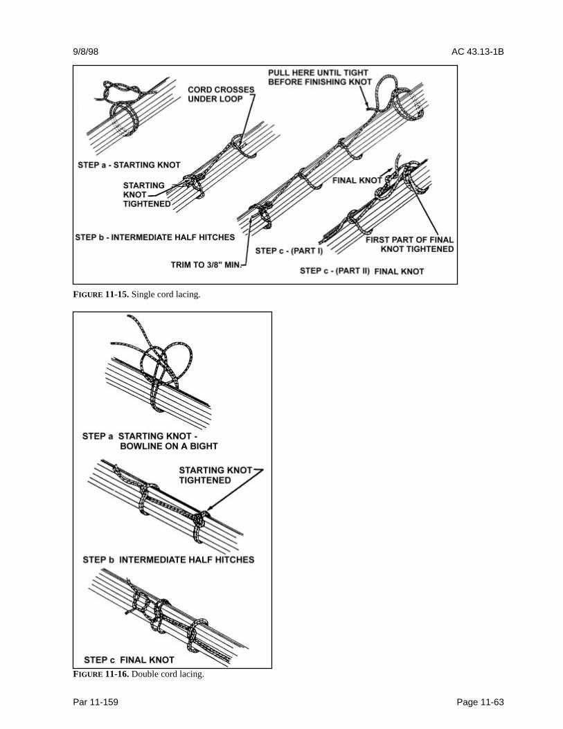
9/8/98 AC 43.13-1B
Par 11-159 Page 11-63
FIGURE 11-15. Single cord lacing.
FIGURE 11-16. Double cord lacing.
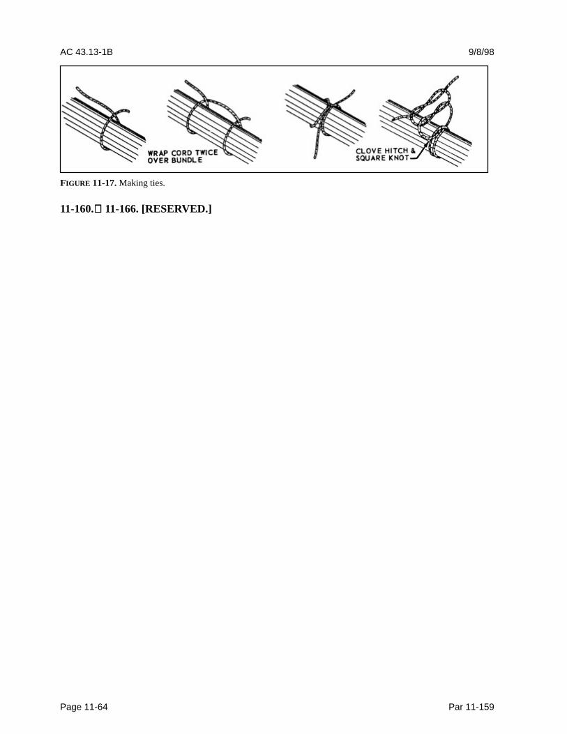
AC 43.13-1B 9/8/98
Page 11-64 Par 11-159
FIGURE 11-17. Making ties.
11-160. 11-166. [RESERVED.]

9/8/98 AC 43.13-1B
Par 11-167 Page 11-65 (and 11-66)
SECTION 13. SPLICING.
11-167. GENERAL. Splicing is permittedon wiring as long as it does not affect the reli-ability and the electromechanical characteris-tics of the wiring. Splicing of power wires,coaxial cables, multiplex bus, and large gaugewire must have approved data.
a. Splicing of electrical wire should bekept to a minimum and avoided entirely inlocations subject to extreme vibrations.Splicing of individual wires in a group or bun-dle should have engineering approval and thesplice(s) should be located to allow periodicinspection.
b. Many types of aircraft splice connec-tors are available for use when splicing indi-vidual wires. Use of a self-insulated spliceconnector is preferred; however, a noninsu-lated splice connector may be used providedthe splice is covered with plastic sleeving thatis secured at both ends. Environmentallysealed splices, that conform to MIL-T-7928,provide a reliable means of splicing inSWAMP areas. However, a noninsulatedsplice connector may be used, provided thesplice is covered with dual wall shrinksleeving of a suitable material.
c. There should not be more than onesplice in any one wire segment between anytwo connectors or other disconnect points, ex-cept; when attaching to the spare pigtail lead ofa potted connector, to splice multiple wires toa single wire, to adjust wire size to fit connec-tor contact crimp barrel size, and to make anapproved repair. (Reference MIL-W-5088,now AS50881A, and NAVAIR 01-1A-505.)
d. Splices in bundles must be staggeredso as to minimize any increase in the size ofthe bundle, preventing the bundle from fittinginto its designated space, or cause congestionthat will adversely affect maintenance. (Seefigure 11-18.)
e. Splices should not be used within12 inches of a termination device, except forparagraph f below.
f. Splices may be used within 12 inchesof a termination device when attaching to thepigtail spare lead of a potted termination de-vice, or to splice multiple wires to a singlewire, or to adjust the wire sizes so that they arecompatible with the contact crimp barrel sizes.
g. Selection of proper crimping tool, re-fer to paragraph 11-178.
FIGURE 11-18. Staggered splices in wire bundle.
11-168. 11-173. [RESERVED.]

9/27/01 AC 43.13-1B CHG 1
Par 11-174 Page 11-67
SECTION 14. TERMINAL REPAIRS
11-174. GENERAL. Terminals are attachedto the ends of electrical wires to facilitate con-nection of the wires to terminal strips or itemsof equipment. The tensile strength of the wire-to-terminal joint should be at least equivalentto the tensile strength of the wire itself, and itsresistance negligible relative to the normal re-sistance of the wire.
a. Selection of Wire Terminals. Thefollowing should be considered in the selectionof wire terminals.
(1) Current rating.
(2) Wire size (gauge) and insulationdiameter.
(3) Conductor material compatibility.
(4) Stud size.
(5) Insulation material compatibility.
(6) Application environment.
(7) Solder/solderless.
Pre-insulated crimp-type ring-tongue terminalsare preferred. The strength, size, and support-ing means of studs and binding posts, as wellas the wire size, should be considered whendetermining the number of terminals to be at-tached to any one post. In high-temperatureapplications, the terminal temperature ratingmust be greater than the ambient temperatureplus current related temperature rise. Use ofnickel-plated terminals and of uninsulated ter-minals with high-temperature insulatingsleeves should be considered. Terminal blocksshould be provided with adequate electricalclearance or insulation strips between mount-ing hardware and conductive parts.
b. Terminal Strips. Wires are usuallyjoined at terminal strips. A terminal strip fit-ted with barriers should be used to prevent theterminals on adjacent studs from contactingeach other. Studs should be anchored againstrotation. When more than four terminals are tobe connected together, a small metal busshould be mounted across two or more adja-cent studs. In all cases, the current should becarried by the terminal contact surfaces and notby the stud itself. Defective studs should bereplaced with studs of the same size and mate-rial since terminal strip studs of the smallersizes may shear due to overtightening the nut.The replacement stud should be securelymounted in the terminal strip and the terminalsecuring nut should be tight. Terminal stripsshould be mounted in such a manner that loosemetallic objects cannot fall across the termi-nals or studs. It is good practice to provide atleast one spare stud for future circuit expan-sion or in case a stud is broken. Terminal stripsthat provide connection of radio and electronicsystems to the aircraft electrical system shouldbe inspected for loose connections, metallicobjects that may have fallen across the termi-nal strip, dirt and grease accumulation, etc.These type conditions can cause arcing whichmay result in a fire, or system failures.
c. Terminal Lugs. Wire terminal lugsshould be used to connect wiring to terminalblock studs or equipment terminal studs. Nomore than four terminal lugs or three terminallugs and a bus bar should be connected to anyone stud. Total number of terminal lugs perstud includes a common bus bar joining adja-cent studs. Four terminal lugs plus a commonbus bar thus are not permitted on one stud.Terminal lugs should be selected with a studhole diameter that matches the diameter of thestud. However, when the terminal lugs at-tached to a stud vary in diameter, the greatest

AC 43.13-1B CHG 1 9/27/01
Page 11-68 Par 11-179
diameter should be placed on the bottom andthe smallest diameter on top. Tightening ter-minal connections should not deform the ter-minal lugs or the studs. Terminal lugs shouldbe so positioned that bending of the terminallug is not required to remove the fasteningscrew or nut, and movement of the terminallugs will tend to tighten the connection.
d. Copper Terminal Lugs. Solderlesscrimp style, copper wire, terminal lugs shouldbe used and conform to MIL-T-7928. Spacersor washers should not be used between thetongues of terminal lugs.
e. Aluminum Terminal Lugs. The alu-minum terminal lugs conforming toMIL-T-7099 (MS-25435, MS-25436,MS-25437, and MS-25438) should be crimpedto aluminum wire only. The tongue of thealuminum terminal lugs or the total number oftongues of aluminum terminal lugs whenstacked, should be sandwiched between twoMS-25440 flat washers when terminated onterminal studs. Spacers or washers should notbe used between the tongues of terminal lugs.Special attention should be given to aluminumwire and cable installations to guard againstconditions that would result in excessive volt-age drop and high resistance at junctions thatmay ultimately lead to failure of the junction.Examples of such conditions are improper in-stallation of terminals and washers, impropertorsion (“torquing” of nuts), and inadequateterminal contact areas.
f. Class 2 Terminal Lugs. The Class 2terminal lugs conforming to MIL-T-7928 maybe used for installation, provided that in suchinstallations, Class 1 terminal lugs are ade-quate for replacement without rework of in-stallation or terminal lugs. Class 2 terminallugs should be the insulated type, unless theconductor temperature exceeds 105 °C. In thatcase uninsulated terminal lugs should be used.Parts’ lists should indicate the appropriate
Class 1 terminal lugs to be used for service re-placement of any Class 2 terminal lugs in-stalled.
g. Termination of Shielded Wire. Fortermination of shielded wire refer toMIL-DTL-27500.
11-175. ATTACHMENT OF TERMI-NALS TO STUDS. Connectors and terminalsin aircraft require special attention to ensure asafe and satisfactory installation. Every possi-bility of short circuits, due to misinstallation,poor maintenance, and service life, should beaddressed in the design. Electrical equipmentmalfunction has frequently been traced to poorterminal connections at terminal boards.Loose, dirty, or corroded contact surfaces canproduce localized heating that may ignitenearby combustible materials or overheat adja-cent wire insulation. (See paragraph 11-178)
11-176. STUDS AND INSULATORS. Thefollowing recommendations concerning studsalso apply to other feed-through conductors.
a. Current Carrying Stud Resistance.Due to heat loss arising from wire-to-lug andlug-to-stud voltage drop, the resistance per unitlength of a current carrying stud should not begreater than that of the wire.
b. Size of Studs. In designing the stud fora feed-through connection, attention should begiven to the higher resistance of brass, as com-pared to copper. A suggested method of de-termining the size is to use a current density inthe stud equivalent to that of the wire, com-pensating for the difference of resistance of themetals. Consideration should also be given tomechanical strength.
c. Support for Studs. The main studsupport in the feed-through insulation shouldbe independent of the attachment of the lugs tothe stud. Therefore, loosening of the insula-tion support of the stud will not affect the
9/27/01 AC 43.13-1B CHG 1
Par 11-174 Page 11-69
electric contact efficiency. In other words, thecontact pressure on the wire lugs should not inany way be affected by the loosening of thestud in the insulator.
d. Support of Wire at Studs. Unlesssome other positive locking action is provided,the lug or wire should be supported next to thestud to prevent loosening the connection with aside pull on the wire. Torque recommenda-tions for attaching electrical wiring devices toterminal boards or blocks, studs, posts, etc.,are normally found in the manufacturer’smaintenance instruction manual.
e. Feed-Through Insulator and StudDesign. Feed-through insulator design shouldbe such as to prevent a loose insulator fromfailing to provide circuit isolation. It shouldnot be able to move from between the stud andthe structure, thus allowing the two to comeinto contact. The assembly should be so de-signed that it is impossible to inadvertentlymisassemble the parts so that faults will result.Also, it is desirable to provide means to pre-vent the feed-through stud from turning whiletightening the connection.
11-177. WIRE TERMINALS AND BIND-ING POSTS. All wire terminals in or onelectrical equipment, except case ground, mustbe firmly held together with two nuts or suit-able locking provisions, or should be securedin a positive manner to equipment in such away that no insulation material is involved inmaintaining physical pressure between thevarious current carrying members of an electri-cal connection. Terminal studs or bindingposts should be of a size that is entirely ade-quate for the current requirements of theequipment and have sufficient mechanicalstrength to withstand the torque required toattach the cable to the equipment. All termi-nals on equipment should have barriers andcovers provided by equipment manufacturers.
11-178. CRIMP ON TERMINAL LUGSAND SPLICES (pre-insulated crimp type).The crimp on terminal lugs and splices mustbe installed using a high quality ratchet-type,crimping tool. We recommend the use of theproper calibrated tool. Aircraft quality crimptools are manufactured to standards. Suchtools are provided with positioners for the wiresize and are adjusted for each wire size. It isessential that the crimp depth be appropriatefor each wire size. If the crimp is too deep ornot deep enough, it may break or cut individ-ual strands, or it may not be tight enough toretain the wire in the terminal or connector.Crimps that are not tight enough are also sus-ceptible to high resistance due to corrosionbuild-up between the crimped terminal and thewire. MIL-C22520/2 or MIL-T-DTl2250Gspecification covers in detail the general re-quirement for crimp tools, inspection gagesand tool kits.
a. Hand, portable, and stationarypower tools are available for crimping termi-nal lugs. These tools crimp the barrel to theconductor, and simultaneously from the insu-lation support to the wire insulation.
b. Crimp tools must be carefully in-spected:
(1) Insure that the full cycle ratchetmechanism is tamper-proof so that it cannot bedisengaged prior to or during the crimp cycle.
(2) If the tool does not function or faultsare found, reject the tool and send the tool tobe repaired.
(3) The tool calibration and adjustmentsare make only by the manufacturer or an ap-proved calibration laboratory.
(4) Suitable gages of the Go/No Gotype are available and shall be used prior to
AC 43.13-1B CHG 1 9/27/01
Page 11-70 Par 11-179
any crimping operation and whenever possibleduring operation to ensure crimp dimensions.
11-179. LOCK WASHERS FOR TERMI-NALS ON EQUIPMENT. Where locknutsare used to ensure binding and locking ofelectrical terminals, they should be of the allmetal type. In addition, a spring lock washerof suitable thickness may be installed underthe nut to ensure good contact pressure. Aplain washer should be used between thespring washer and the terminal to preventgalling. A plain nut with a spring lock washerand a plain washer may be used to providebinding and contact pressure.
11-180. 11-184. [RESERVED.]
9/27/01 AC 43.13-1B CHG 1
Par 11-185 Page 11-71
SECTION 15. GROUNDING AND BONDING
11-185. GENERAL. One of the more im-portant factors in the design and maintenanceof aircraft electrical systems is proper bondingand grounding. Inadequate bonding orgrounding can lead to unreliable operation ofsystems, e.g., EMI, electrostatic dischargedamage to sensitive electronics, personnelshock hazard, or damage from lightning strike.This section provides an overview of the prin-ciples involved in the design and maintenanceof electrical bonding and grounding.SAE ARP-1870 provides for more completedetailed information on grounding and bond-ing, and the application of related hardware.
11-186. GROUNDING. Grounding is theprocess of electrically connecting conductiveobjects to either a conductive structure or someother conductive return path for the purpose ofsafely completing either a normal or fault cir-cuit.
a. Types of Grounding. If wires carryingreturn currents from different types of sources,such as signals of DC and AC generators, areconnected to the same ground point or have acommon connection in the return paths, an in-teraction of the currents will occur. Mixingreturn currents from various sources should beavoided because noise will be coupled fromone source to another and can be a majorproblem for digital systems. To minimize theinteraction between various return currents,different types of grounds should be identifiedand used. As a minimum, the design shoulduse three ground types: (1) ac returns, (2) dcreturns, and (3) all others. For distributedpower systems, the power return point for analternative power source would be separated.For example, in a two-ac generator (one on theright side and the other on the left side) sys-tem, if the right ac generator were supplyingbackup power to equipment located in the leftside, (left equipment rack) the backup ac
ground return should be labeled “ac Right”.The return currents for the left generatorshould be connected to a ground point labeled“ac Left”
b. Current Return Paths. The design ofthe ground return circuit should be given asmuch attention as the other leads of a circuit.A requirement for proper ground connectionsis that they maintain an impedance that is es-sentially constant. Ground return circuitsshould have a current rating and voltage dropadequate for satisfactory operation of the con-nected electrical and electronic equipment.EMI problems, that can be caused by a sys-tem’s power wire, can be reduced substantiallyby locating the associated ground return nearthe origin of the power wiring (e.g. circuitbreaker panel) and routing the power wire andits ground return in a twisted pair. Special careshould be exercised to ensure replacement onground return leads. The use of numbered in-sulated wire leads instead of bare groundingjumpers may aid in this respect. In general,equipment items should have an externalground connection, even when internallygrounded. Direct connections to a magnesium(which may create a fire hazard) structure mustnot be used for ground return.
c. Heavy-Current Grounds. Powerground connections, for generators, trans-former rectifiers, batteries, external power re-ceptacles, and other heavy-current, loads mustbe attached to individual grounding bracketsthat are attached to aircraft structure with aproper metal-to-metal bonding attachment.This attachment and the surrounding structuremust provide adequate conductivity to ac-commodate normal and fault currents of thesystem without creating excessive voltage dropor damage to the structure. At least three fas-teners, located in a triangular or rectangularpattern, must be used to secure such brackets
AC 43.13-1B CHG 1 9/27/01
Page 11-72 Par 11-186
in order to minimize susceptibility to loosen-ing under vibration. If the structure is fabri-cated of a material such as carbon fiber com-posite (CFC), which has a higher resistivitythan aluminum or copper, it will be necessaryto provide an alternative ground path(s) forpower return current. Special attention shouldbe considered for composite aircraft.
d. Current Return Paths for InternallyGrounded Equipment. Power return or faultcurrent ground connections within flammablevapor areas must be avoided. If they must bemade, make sure these connections will notarc, spark, or overheat under all possible cur-rent flow or mechanical failure conditions, in-cluding induced lightning currents. Criteriafor inspection and maintenance to ensure con-tinued airworthiness throughout the expectedlife of the aircraft should be established.Power return fault currents are normally thehighest currents flowing in a structure. Thesecan be the full generator current capacity. Iffull generator fault current flows through a lo-calized region of the carbon fiber structure,major heating and failure can occur. CFC andother similar low-resistive materials must notbe used in power return paths. Additionalvoltage drops in the return path can cause volt-age regulation problems. Likewise, repeatedlocalized material heating by current surgescan cause material degradation. Both prob-lems may occur without warning and causenonrepeatable failures or anomalies.
e. Common Ground Connections. Theuse of common ground connections for morethan one circuit or function should be avoidedexcept where it can be shown that related mal-functions that could affect more than one cir-cuit will not result in a hazardous condition.Even when the loss of multiple systems doesnot, in itself, create a hazard, the effect of suchfailure can be quite distracting to the crew.
(1) Redundant systems are normallyprovided with the objective of assuring contin-ued safe operation in the event of failure of asingle channel and must therefore be groundedat well separated points. To avoid constructionor maintenance errors that result in connectingsuch ground at a single point, wires thatground one channel of a redundant systemshould be incapable of reaching the groundattachment of the other channel.
(2) The use of loop type groundingsystems (several ground leads connected in se-ries with a ground to structure at each end)must be avoided on redundant systems, be-cause the loss of either ground path will re-main undetected, leaving both systems, with apotential single-point failure.
(3) Electrical power sources must begrounded at separate locations on the aircraftstructure. The loss of multiple sources ofelectrical power, as the result of corrosion of aground connection or failure of the relatedfasteners, may result in the loss of multiplesystems and should be avoided by making theground attachments at separate locations.
(4) Bonds to thermally or vibration-isolated structure require special considerationto avoid single ground return to primarystructure.
(5) The effect of the interconnection ofthe circuits when ungrounded should be con-sidered whenever a common ground connec-tion is used. This is particularly importantwhen employing terminal junction groundingmodules or other types of gang grounds thathave a single attachment point.
9/8/98 AC 43.13-1B
Par 11-186 Page 11-73
f. Grounds for Sensitive Circuits. Spe-cial consideration should be given to groundsfor sensitive circuits. For example:
(1) Grounding of a signal circuitthrough a power current lead introduces powercurrent return voltage drop into the signal cir-cuit.
(2) Running power wires too close willcause signal interference.
(3) Separately grounding two compo-nents of a transducer system may introduceground plane voltage variations into the sys-tem.
(4) Single point grounds for signal cir-cuits, with such grounds being at the signalsource, are often a good way to minimize theeffects of EMI, lightning, and other sources ofinterference.
11-187. BONDING. The following bondingrequirements must be considered:
a. Equipment Bonding. Low-impedancepaths to aircraft structure are normally requiredfor electronic equipment to provide radio fre-quency return circuits and for most electricalequipment to facilitate reduction in EMI. Thecases of components which produce electro-magnetic energy should be grounded to struc-ture. To ensure proper operation of electronicequipment, it is particularly important to con-form the system’s installation specificationwhen interconnections, bonding, and ground-ing are being accomplished.
b. Metallic Surface Bonding. All con-ducting objects on the exterior of the airframemust be electrically connected to the airframethrough mechanical joints, conductive hinges,or bond straps capable of conducting staticcharges and lightning strikes. Exceptions may
be necessary for some objects such as antennaelements, whose function requires them to beelectrically isolated from the airframe. Suchitems should be provided with an alternativemeans to conduct static charges and/or light-ning currents, as appropriate.
c. Static Bonds. All isolated conductingparts inside and outside the aircraft, having anarea greater than 3 in2 and a linear dimensionover 3 inches, that are subjected to appreciableelectrostatic charging due to precipitation,fluid, or air in motion, should have a mechani-cally secure electrical connection to the aircraftstructure of sufficient conductivity to dissipatepossible static charges. A resistance of lessthan 1 ohm when clean and dry will generallyensure such dissipation on larger objects.Higher resistances are permissible in connect-ing smaller objects to airframe structure.
11-188. BONDING INSPECTION. In-spect for the following:
a. If there is evidence of electrical arc-ing, check for intermittent electrical contactbetween conducting surfaces, that may becomea part of a ground plane or a current path.Arcing can be prevented either by bonding, orby insulation if bonding is not necessary.
b. The metallic conduit should bebonded to the aircraft structure at each termi-nating and break point. The conduit bondingstrap should be located ahead of the piece ofequipment that is connected to the cable wireinside the conduit.
c. Bond connections should be secure andfree from corrosion.
d. Bonding jumpers should be installedin such a manner as not to interfere in any waywith the operation of movable components ofthe aircraft.
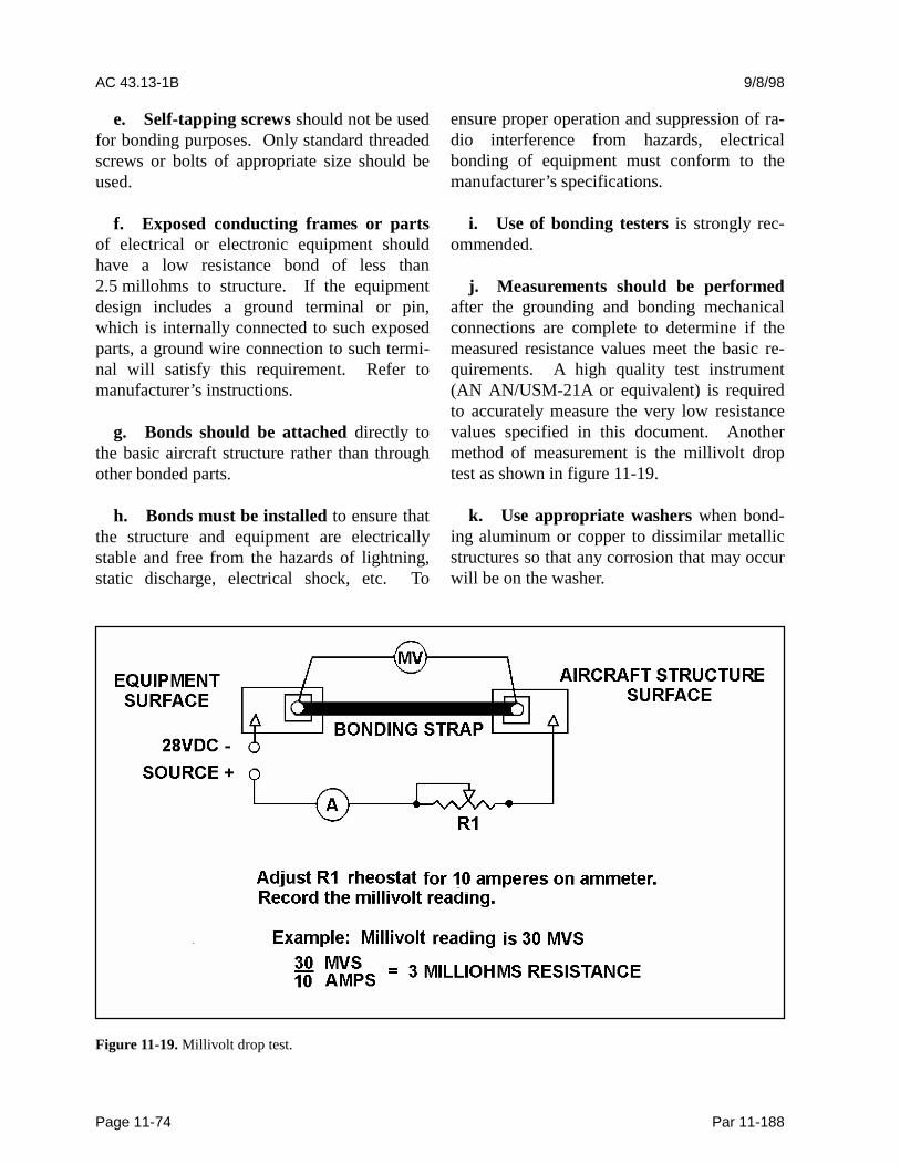
AC 43.13-1B 9/8/98
Page 11-74 Par 11-188
e. Self-tapping screws should not be usedfor bonding purposes. Only standard threadedscrews or bolts of appropriate size should beused.
f. Exposed conducting frames or partsof electrical or electronic equipment shouldhave a low resistance bond of less than2.5 millohms to structure. If the equipmentdesign includes a ground terminal or pin,which is internally connected to such exposedparts, a ground wire connection to such termi-nal will satisfy this requirement. Refer tomanufacturer’s instructions.
g. Bonds should be attached directly tothe basic aircraft structure rather than throughother bonded parts.
h. Bonds must be installed to ensure thatthe structure and equipment are electricallystable and free from the hazards of lightning,static discharge, electrical shock, etc. To
ensure proper operation and suppression of ra-dio interference from hazards, electricalbonding of equipment must conform to themanufacturer’s specifications.
i. Use of bonding testers is strongly rec-ommended.
j. Measurements should be performedafter the grounding and bonding mechanicalconnections are complete to determine if themeasured resistance values meet the basic re-quirements. A high quality test instrument(AN AN/USM-21A or equivalent) is requiredto accurately measure the very low resistancevalues specified in this document. Anothermethod of measurement is the millivolt droptest as shown in figure 11-19.
k. Use appropriate washers when bond-ing aluminum or copper to dissimilar metallicstructures so that any corrosion that may occurwill be on the washer.
Figure 11-19. Millivolt drop test.
9/8/98 AC 43.13-1B
Par 11-189 Page 11-75
11-189. BONDING JUMPER INSTAL-LATIONS. Bonding jumpers should be madeas short as practicable, and installed in such amanner that the resistance of each connectiondoes not exceed .003 ohm. The jumper shouldnot interfere with the operation of movableaircraft elements, such as surface controls, norshould normal movement of these elements re-sult in damage to the bonding jumper.
a. Bonding Connections. To ensure alow-resistance connection, nonconducting fin-ishes, such as paint and anodizing films,should be removed from the attachment sur-face to be contacted by the bonding terminal.On aluminum surfaces, a suitable conductivechemical surface treatment, such as Alodine,should be applied to the surfaces within24 hours of the removal of the original finish.Refer to SAE, ARP 1870 for detailed instruc-tions. Electric wiring should not be groundeddirectly to magnesium parts.
b. Corrosion Protection. One of themore frequent causes of failures in electricalsystem bonding and grounding is corrosion.Aircraft operating near salt water are particu-larly vulnerable to this failure mode. Becausebonding and grounding connections may in-volve a variety of materials and finishes, it isimportant to protect completely against dis-similar metal corrosion. The areas aroundcompleted connections should be post-finishedin accordance with the original finish require-ments or with some other suitable protectivefinish within 24 hours of the cleaning process.In applications exposed to salt spray environ-ment, a suitable noncorrosive sealant, such asone conforming to MIL-S-8802, should beused to seal dissimilar metals for protectionfrom exposure to the atmosphere.
c. Corrosion Prevention. Electrolyticaction may rapidly corrode a bonding connec-tion if suitable precautions are not taken.Aluminum alloy jumpers are recommended formost cases; however, copper jumpers shouldbe used to bond together parts made of stain-less steel, cadmium plated steel, copper, brass,or bronze. Where contact between dissimilarmetals cannot be avoided, the choice of jumperand hardware should be such that corrosion isminimized, and the part likely to corrodewould be the jumper or associated hardware.Tables 11-14 through 11-16 and figures 11-20through 11-22 show the proper hardware com-binations for making a bond connection. Atlocations where finishes are removed, a pro-tective finish should be applied to the com-pleted connection to prevent subsequentcorrosion.
d. Bonding Jumper Attachment. Theuse of solder to attach bonding jumpers shouldbe avoided. Tubular members should bebonded by means of clamps to which thejumper is attached. Proper choice of clampmaterial should minimize the probability ofcorrosion.
e. Ground Return Connection. Whenbonding jumpers carry substantial ground re-turn current, the current rating of the jumpershould be determined to be adequate and thata negligible voltage drop is produced.
11-190. CREEPAGE DISTANCE. Careshould be used in the selection of electricalcomponents to ensure that electrical clearanceand creepage distance along surfaces betweenadjacent terminals, at different potentials, andbetween these terminals and adjacent groundsurfaces are adequate for the voltages in-volved.
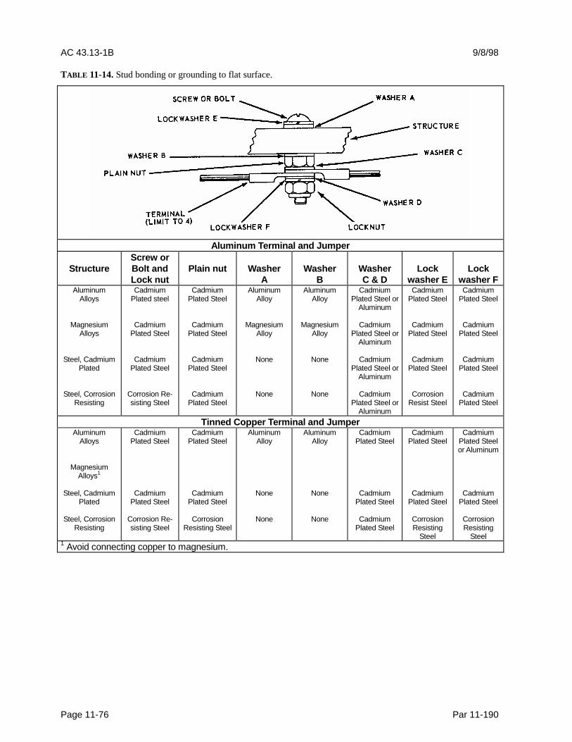
AC 43.13-1B 9/8/98
Page 11-76 Par 11-190
TABLE 11-14. Stud bonding or grounding to flat surface.
Aluminum Terminal and Jumper
StructureScrew orBolt andLock nut
Plain nut WasherA
WasherB
WasherC & D
Lockwasher E
Lockwasher F
AluminumAlloys
MagnesiumAlloys
Steel, CadmiumPlated
Steel, CorrosionResisting
CadmiumPlated steel
CadmiumPlated Steel
CadmiumPlated Steel
Corrosion Re-sisting Steel
CadmiumPlated Steel
CadmiumPlated Steel
CadmiumPlated Steel
CadmiumPlated Steel
AluminumAlloy
MagnesiumAlloy
None
None
AluminumAlloy
MagnesiumAlloy
None
None
CadmiumPlated Steel or
Aluminum
CadmiumPlated Steel or
Aluminum
CadmiumPlated Steel or
Aluminum
CadmiumPlated Steel or
Aluminum
CadmiumPlated Steel
CadmiumPlated Steel
CadmiumPlated Steel
CorrosionResist Steel
CadmiumPlated Steel
CadmiumPlated Steel
CadmiumPlated Steel
CadmiumPlated Steel
Tinned Copper Terminal and JumperAluminum
Alloys
MagnesiumAlloys1
Steel, CadmiumPlated
Steel, CorrosionResisting
CadmiumPlated Steel
CadmiumPlated Steel
Corrosion Re-sisting Steel
CadmiumPlated Steel
CadmiumPlated Steel
CorrosionResisting Steel
AluminumAlloy
None
None
AluminumAlloy
None
None
CadmiumPlated Steel
CadmiumPlated Steel
CadmiumPlated Steel
CadmiumPlated Steel
CadmiumPlated Steel
CorrosionResisting
Steel
CadmiumPlated Steelor Aluminum
CadmiumPlated Steel
CorrosionResisting
Steel1 Avoid connecting copper to magnesium.
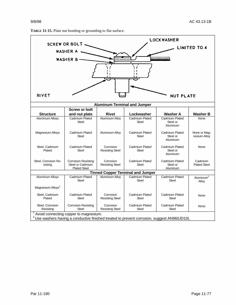
9/8/98 AC 43.13-1B
Par 11-190 Page 11-77
TABLE 11-15. Plate nut bonding or grounding to flat surface.
Aluminum Terminal and Jumper
StructureScrew or boltand nut plate Rivet Lockwasher Washer A Washer B
Aluminum Alloys
Magnesium Alloys
Steel, CadmiumPlated
Steel, Corrosion Re-sisting
Cadmium PlatedSteel
Cadmium PlatedSteel
Cadmium PlatedSteel
Corrosion ResistingSteel or Cadmium
Plated Steel
Aluminum Alloy
Aluminum Alloy
CorrosionResisting Steel
CorrosionResisting Steel
Cadmium PlatedSteel
Cadmium PlatedSteel
Cadmium PlatedSteel
Cadmium PlatedSteel
Cadmium PlatedSteel or
Aluminum
Cadmium PlatedSteel or
Aluminum
Cadmium PlatedSteel or
Aluminum
Cadmium PlatedSteel or
Aluminum
None
None or Mag-nesium Alloy
None
CadmiumPlated Steel
Tinned Copper Terminal and JumperAluminum Alloys
Magnesium Alloys1
Steel, CadmiumPlated
Steel, CorrosionResisting
Cadmium PlatedSteel
Cadmium PlatedSteel
Corrosion ResistingSteel
Aluminum Alloy
CorrosionResisting Steel
CorrosionResisting Steel
Cadmium PlatedSteel
Cadmium PlatedSteel
Cadmium PlatedSteel
Cadmium PlatedSteel
Cadmium PlatedSteel
Cadmium PlatedSteel
Aluminum2
Alloy
None
None
1 Avoid connecting copper to magnesium.2.Use washers having a conductive finished treated to prevent corrosion, suggest AN960JD10L
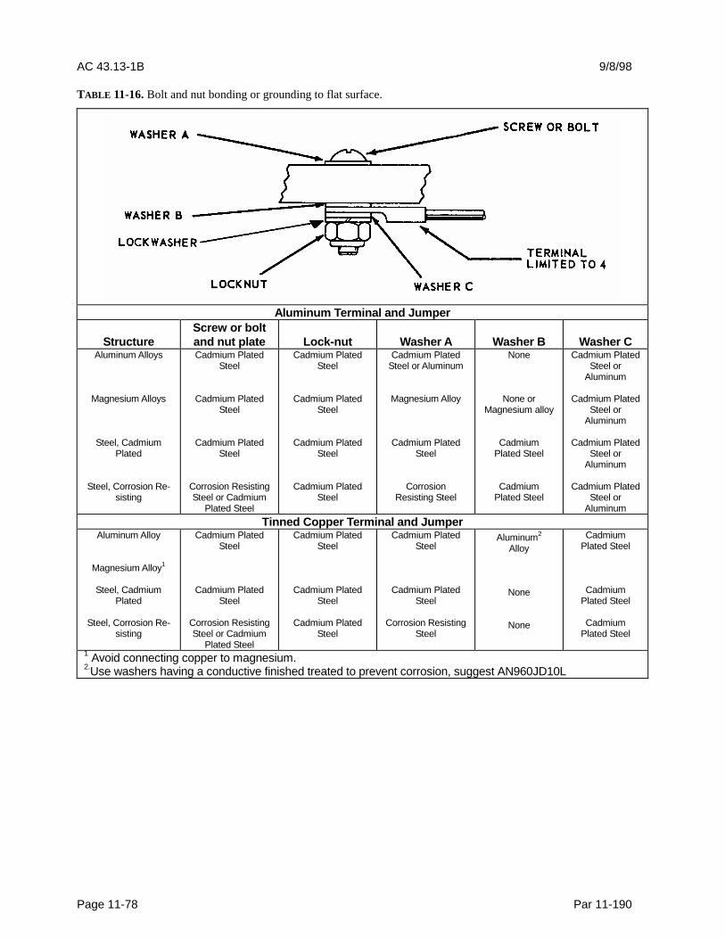
AC 43.13-1B 9/8/98
Page 11-78 Par 11-190
TABLE 11-16. Bolt and nut bonding or grounding to flat surface.
Aluminum Terminal and Jumper
StructureScrew or boltand nut plate Lock-nut Washer A Washer B Washer C
Aluminum Alloys
Magnesium Alloys
Steel, CadmiumPlated
Steel, Corrosion Re-sisting
Cadmium PlatedSteel
Cadmium PlatedSteel
Cadmium PlatedSteel
Corrosion ResistingSteel or Cadmium
Plated Steel
Cadmium PlatedSteel
Cadmium PlatedSteel
Cadmium PlatedSteel
Cadmium PlatedSteel
Cadmium PlatedSteel or Aluminum
Magnesium Alloy
Cadmium PlatedSteel
CorrosionResisting Steel
None
None orMagnesium alloy
CadmiumPlated Steel
CadmiumPlated Steel
Cadmium PlatedSteel or
Aluminum
Cadmium PlatedSteel or
Aluminum
Cadmium PlatedSteel or
Aluminum
Cadmium PlatedSteel or
AluminumTinned Copper Terminal and Jumper
Aluminum Alloy
Magnesium Alloy1
Steel, CadmiumPlated
Steel, Corrosion Re-sisting
Cadmium PlatedSteel
Cadmium PlatedSteel
Corrosion ResistingSteel or Cadmium
Plated Steel
Cadmium PlatedSteel
Cadmium PlatedSteel
Cadmium PlatedSteel
Cadmium PlatedSteel
Cadmium PlatedSteel
Corrosion ResistingSteel
Aluminum2
Alloy
None
None
CadmiumPlated Steel
CadmiumPlated Steel
CadmiumPlated Steel
1 Avoid connecting copper to magnesium.2.Use washers having a conductive finished treated to prevent corrosion, suggest AN960JD10L
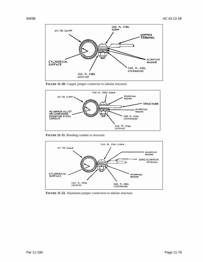
9/8/98 AC 43.13-1B
Par 11-190 Page 11-79
FIGURE 11-20. Copper jumper connector to tubular structure.
FIGURE 11-21. Bonding conduit to structure.
FIGURE 11-22. Aluminum jumper connection to tubular structure.
AC 43.13-1B 9/8/98
Page 11-80 Par 11-191
11-191. FUEL SYSTEMS. Small metallicobjects within an aircraft fuel tank, that are notpart of the tank structure, should be electricallybonded to the structure so as to dissipate staticcharges that may otherwise accumulate onthese objects. A practical bonding designwould use a flexible braided jumper wire orriveted bracket. In such situations, a DC re-sistance of 1 ohm or less should indicate anadequate connection. Care should be taken, indesigning such connections, to avoid creatingcontinuous current paths that could allowlightning or power fault currents to passthrough connections not designed to toleratethese higher amplitude currents without arcing.Simulated static charge, lightning, or fault cur-rent tests may be necessary to establish or ver-ify specific designs. All other fuel systemcomponents, such as fuel line (line to line) ac-cess doors, fuel line supports, structural parts,fuel outlets, or brackets should have an elec-tromechanical (bonding strap) secure connec-tor that ensures 1 ohm or less resistance to thestructure. Advisory Circular 20-53A Protec-tion of Aircraft Fuel Systems Against Fuel Va-por Ignition Due to Lightning, and associatemanual DOT/FAA/ CT-83/3, provide detailedinformation on necessary precautions.
11-192. ELECTRIC SHOCK PREVEN-TION BONDING. Electric shock to person-nel should be prevented by providing a low re-sistance path of 1/100 ohm or less betweenstructure and metallic conduits or equipment.The allowable ground resistance should besuch that the electric potential of the conduit orequipment housing does not reach a dangerousvalue under probable fault conditions. Thecurrent carrying capacity of all elements of theground circuit should be such that, under thefault condition, no sparking, fusion, or danger-ous heating will occur. Metallic supports usu-ally provide adequate bonding if metal-to-metal contact is maintained.
11-193. LIGHTNING PROTECTIONBONDING. Electrical bonding is frequentlyrequired for lightning protection of aircraft andsystems, especially to facilitate safe conduc-tion of lightning currents through the airframe.Most of this bonding is achieved through nor-mal airframe riveted or bolted joints but someexternally mounted parts, such as control sur-faces, engine nacelles, and antennas, may re-quire additional bonding provisions. Gener-ally, the adequacy of lightning current bondsdepends on materials, cross-sections, physicalconfigurations, tightness, and surface finishes.Care should be taken to minimize structural re-sistance, so as to control structural voltagerises to levels compatible with system protec-tion design. This may require that metal sur-faces be added to composite structures, or thattinned copper overbraid, conduits, or cabletrays be provided for interconnecting wire har-nesses within composite airframes. Also caremust be taken to prevent hazardous lightningcurrents from entering the airframe via flightcontrol cables, push rods, or other conductingobjects that extend to airframe extremities.This may require that these conductors beelectrically bonded to the airframe, or thatelectrical insulators be used to interrupt light-ning currents. For additional information onlightning protection measures, refer toDOT/FAA/CT-89-22. Report DOT/FAA/CT 86/8, April 1987, Determination of Electri-cal Properties of Bonding and Fastening Tech-niques may provide additional information forcomposite materials.
a. Control Surface Lightning ProtectionBonding. Control surface bonding is intendedto prevent the burning of hinges on a surfacethat receives a lightning strike; thus causingpossible loss of control. To accomplish thisbonding, control surfaces and flaps shouldhave at least one 6500 circular mil area copper(e.g. 7 by 37 AWG size 36 strands) jumper
9/8/98 AC 43.13-1B
Par 11-193 Page 11-81 (and 11-82)
across each hinge. In any case, not less thantwo 6500 circular mil jumpers should be usedon each control surface. The installation loca-tion of these jumpers should be carefully cho-sen to provide a low-impedance shunt forlightning current across the hinge to the struc-ture. When jumpers may be subjected to arc-ing, substantially larger wire sizes of40,000 circular mils or a larger cross sectionare required to provide protection against mul-tiple strikes. Sharp bends and loops in suchjumpers can create susceptibility to breakagewhen subjected to the inductive forces createdby lightning current, and should be avoided.
b. Control Cable Lightning ProtectionBonding. To prevent damage to the controlsystem or injury to flight personnel due tolightning strike, cables and levers coming fromeach control surface should be protected byone or more bonding jumpers located as closeto the control surface as possible. Metal pul-leys are considered a satisfactory ground forcontrol cables.
11-194. LIGHTNING PROTECTIONFOR ANTENNAS AND AIR DATAPROBES. Antenna and air data probes thatare mounted on exterior surfaces within light-ning strike zones should be provided with ameans to safely transfer lightning currents tothe airframe, and to prevent hazardous surgesfrom being conducted into the airframe viaantenna cables or wire harnesses. Usually, theantenna mounting bolts provide adequatelightning current paths. Surge protectors builtinto antennas or installed in coaxial antennacables or probe wire harnesses will fulfill theserequirements. Candidate designs should beverified by simulated lightning tests in accor-dance with RTCA DO-160C, Section 23.
11-195. STATIC-DISCHARGE DEVICE.Means should be provided to bleed accumu-lated static charges from aircraft prior to
ground personnel coming in contact with anaircraft after landing. Normally, there is ade-quate conductivity in the tires for this, but ifnot, a static ground should be applied beforepersonnel come into contact with the aircraft.Fuel nozzle grounding receptacles should beinstalled in accordance with the manufac-turer’s specifications. Grounding receptaclesshould provide a means to eliminate the static-induced voltage that might otherwise cause aspark between a fuel nozzle and fuel tank ac-cess covers and inlets. In addition, static dis-charging wicks are installed on wings and tailsurfaces to discharge static changes while inflight.
11-196. CLEANING. In order to ensureproper ground connection conductivity, allpaint, primer, anodize coating, grease, andother foreign material must be carefully re-moved from areas that conduct electricity. Onaluminum surfaces, apply chemical surfacetreatment to the cleaned bare metal surface inaccordance with the manufacturer’s instruc-tions within 4-8 hours, depending on ambientmoisture/contaminate content.
11-197. HARDWARE ASSEMBLY. De-tails of bonding connections must be de-scribed in maintenance manuals and adhered tocarefully when connections are removed or re-placed during maintenance operations. In or-der to avoid corrosion problems and ensurelong-term integrity of the electrical connection,hardware used for this purpose must be as de-fined in these documents or at least beequivalent in material and surface. Installationof fasteners used in bonded or grounded con-nections should be made in accordance withSAE ARP-1870. Threaded fasteners must betorqued to the level required by SAEARP-1928.
11-198. 11-204. [RESERVED.]


9/27/01 AC 43.13-1B CHG 1
Par 11-205 Page 11-83
SECTION 16. WIRE MARKING
11-205. GENERAL. The proper identifica-tion of electrical wires and cables with theircircuits and voltages is necessary to providesafety of operation, safety to maintenance per-sonnel, and ease of maintenance.
a. Each wire and cable should be markedwith a part number. It is common practice forwire manufacturers to follow the wire materialpart number with the five digit/letter C.A.G.E.code identifying the wire manufacturer. Ex-isting installed wire that needs replacement canthereby be identified as to its performance ca-pabilities, and the inadvertent use of a lowerperformance and unsuitable replacement wireavoided.
b. The method of identification shouldnot impair the characteristics of the wiring.
CAUTION: Do not use metallic bandsin place of insulating sleeves. Exercisecare when marking coaxial or databus cable, as deforming the cable maychange its electrical characteristics.
11-206. WIRE IDENTIFICATION. To fa-cilitate installation and maintenance, originalwire-marking identification is to be retained.The wire identification marks should consist ofa combination of letters and numbers thatidentify the wire, the circuit it belongs to, itsgauge size, and any other information to relatethe wire to a wiring diagram. All markingsshould be legible in size, type, and color.
11-207. IDENTIFICATION AND IN-FORMATION RELATED TO THE WIREAND WIRING DIAGRAMS. The wireidentification marking should consist of simi-lar information to relate the wire to a wiringdiagram.
11-208. PLACEMENT OF IDENTIFI-CATION MARKINGS. Identificationmarkings should be placed at each end of thewire and at 15-inch maximum intervals alongthe length of the wire. Wires less than 3 incheslong need not be identified. Wires 3 to7 inches in length should be identified ap-proximately at the center. Added identificationmarker sleeves should be so located that ties,clamps, or supporting devices need not be re-moved in order to read the identification.
The wire identification code must be printed toread horizontally (from left to right) or verti-cally (from top to bottom). The two methodsof marking wire or cable are as follows:
a. Direct marking is accomplished byprinting the cable’s outer covering. (See fig-ure 11-23.)
b. Indirect marking is accomplished byprinting a heat-shrinkable sleeve and installingthe printed sleeve on the wire or cables outercovering. Indirect-marked wire or cableshould be identified with printed sleeves ateach end and at intervals not longer than 6 feet.The individual wires inside a cable should beidentified within 3 inches of their termination.(See figure 11-24.)
11-209. TYPES OF WIRE MARKINGS.The preferred method is to mark directly onthe wire. A successful requirement qualifica-tion should produce markings that meet themarking characteristics specified in MIL-W-5088 or AS50881A without causing insulationdegradation. Teflon coated wires, shieldedwiring, multi-conductor cable, and thermocou-ple wires usually require special sleeves tocarry identification marks. There are somewire marking machines in the market that canbe used to stamp directly on the type wiresmentioned above. Whatever method of mark-ing is used, the marking should be legible and

AC 43.13-1B CHG 1 9/27/01
Page 11-84 Par 11-209
the color should contrast with the wire insula- tion or sleeve.
FIGURE 11-23. Spacing of printed identification marks (direct marking).
FIGURE 11-24. Spacing of printed identification marks(indirect marking).
a. Extreme care must, therefore, be takenduring circuit identification by a hot stampmachine on insulation wall 10 mils or thinner.
b. Alternative identification methodssuch as “Laser Printing”, “Ink Jet”, and “DotMatrix” are preferred. When such modernequipment is not available, the use of stampedidentification sleeving should be considered oninsulation wall thickness of 10 mils or less.
11-210. HOT STAMP MARKING. Due towidespread use of hot stamp wire marking,personnel should refer to SAE ARP5369,Guidelines for Wire Identification Markingusing the Hot Stamp Process, for guidance onminimizing insulation damage. Hot stampprocess uses a heated typeface to transfer pig-ment from a ribbon or foil to the surface ofwires or cables. The traditional method im-prints hot ink marks onto the wire. Exercisecaution when using this method, as it has beenshown to damage insulation when incorrectlyapplied. Typeset characters, similar to thatused in printing presses but shaped to the
3” 15” 15” 3”H215A20 H215A20 H215A20
(b) Single wire without sleeve
9/27/01 AC 43.13-1B CHG 1
Par 11-221 Pages 11-85
contour of the wire, are heated to the desiredtemperature. Wire is pulled through a channeldirectly underneath the characters. The heat ofthe type set characters transfers the ink fromthe marking foil onto the wire.
a. Good marking is obtained only by theproper combination of temperature, pressure,and dwelling. Hot stamp will mark wire withan outside diameter of 0.038 to 0.25-inch.
b. Before producing hot stamp wire, itmust be assured that the marking machine isproperly adjusted to provide the best wiremarking with the least wire insulation deterio-ration. The marking should never create anindent greater than 10 percent of the insulationwall.
CAUTION: The traditional HotStamp method is not recommendedfor use on wire with outside diametersof less than 0.035. (REF. SAEARP5369). Stamping dies may causefracture of the insulation wall andpenetration to the conductor of thesematerials. When various fluids wetthese opening in service, arcing andsurface tracking damage wire bun-dles. Later in service, when variousfluids have wet these openings, seriousarcing and surface tracking will havedamaged wire bundles.
11-211. DOT MATRIX MARKING. Thedot matrix marking is imprinted onto the wireor cable very similar to that of a dot matrixcomputer printer. The wire must go through acleaning process to make sure it is clean anddry for the ink to adhere. Wires marked withdot matrix equipment require a cure consistingof an UV curing process, which is normallyapplied by the marking equipment. This cureshould normally be complete 16 to 24 hoursafter marking. Dot matrix makes a legiblemark without damaging the insulation. De
pending on equipment configuration, dot ma-trix can mark wire from 0.037 to 0.5-inch out-side diameter. Multi-conductor cable can alsobe marked.
11-212. INK JET MARKING. This is a“non-impact” marking method wherein inkdroplets are electrically charged and then di-rected onto the moving wire to form the char-acters. Two basic ink types are available:thermal cure and UV cure.
a. Thermal cure inks must generally beheated in an oven for a length of time aftermarking to obtain their durability. UV cureinks are cured in line much like dot matrix.
b. Ink jet marks the wire on the fly andmakes a reasonably durable and legible markwithout damaging the insulation. Ink jetsnormally mark wire from 0.030 to 0.25-inchoutside diameter. Multiconductor cable canalso be marked.
11-213. LASER MARKING. Of the varietyof laser marking machines, UV lasers areproving to be the best. This method marksinto the surface of the wire’s insulation withoutdegradation to its performance. One commontype of UV laser is referred to as an excimerlaser marker. UV laser produces the most du-rable marks because it marks into the insula-tion instead of on the surface. However, exci-mer laser will only mark insulation that con-tain appropriate percentages of titanium diox-ide (TiO2). The wire can be marked on the fly.UV can mark from 0.030 to 0.25-inch outsidediameter. The UV laser makes only graymarks and they appear more legible on whiteor pastel-colored insulation.
11-214. IDENTIFICATION SLEEVES.Flexible sleeving, either clear or opaque, issatisfactory for general use. When color-codedor striped component wire is used as part of acable, the identification sleeve should
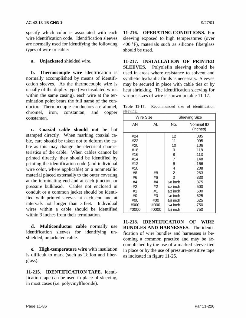
AC 43.13-1B CHG 1 9/27/01
Page 11-86 Par 11-220
specify which color is associated with eachwire identification code. Identification sleevesare normally used for identifying the followingtypes of wire or cable:
a. Unjacketed shielded wire.
b. Thermocouple wire identification isnormally accomplished by means of identifi-cation sleeves. As the thermocouple wire isusually of the duplex type (two insulated wireswithin the same casing), each wire at the ter-mination point bears the full name of the con-ductor. Thermocouple conductors are alumel,chromel, iron, constantan, and copperconstantan.
c. Coaxial cable should not be hotstamped directly. When marking coaxial ca-ble, care should be taken not to deform the ca-ble as this may change the electrical charac-teristics of the cable. When cables cannot beprinted directly, they should be identified byprinting the identification code (and individualwire color, where applicable) on a nonmetallicmaterial placed externally to the outer coveringat the terminating end and at each junction orpressure bulkhead. Cables not enclosed inconduit or a common jacket should be identi-fied with printed sleeves at each end and atintervals not longer than 3 feet. Individualwires within a cable should be identifiedwithin 3 inches from their termination.
d. Multiconductor cable normally useidentification sleeves for identifying un-shielded, unjacketed cable.
e. High-temperature wire with insulationis difficult to mark (such as Teflon and fiber-glass).
11-215. IDENTIFICATION TAPE. Identi-fication tape can be used in place of sleeving,in most cases (i.e. polyvinylfluoride).
11-216. OPERATING CONDITIONS. Forsleeving exposed to high temperatures (over400 °F), materials such as silicone fiberglassshould be used.
11-217. INSTALLATION OF PRINTEDSLEEVES. Polyolefin sleeving should beused in areas where resistance to solvent andsynthetic hydraulic fluids is necessary. Sleevesmay be secured in place with cable ties or byheat shrinking. The identification sleeving forvarious sizes of wire is shown in table 11-17.
Table 11-17. Recommended size of identificationsleeving.
Wire Size Sleeving Size
AN AL No. Nominal ID(inches)
#24#22#20#18#16#14#12#10#8#6#4#2#1#0#00#000#0000
#8#6#4#2#1#0#00#000#0000
1211109876420
3/8 inch1/2 inch1/2 inch5/8 inch5/8 inch3/4 inch3/4 inch
.085
.095
.106
.118
.113
.148
.166
.208
.263
.330
.375
.500
.500
.625
.625
.750
.750
11-218. IDENTIFICATION OF WIREBUNDLES AND HARNESSES. The identi-fication of wire bundles and harnesses is be-coming a common practice and may be ac-complished by the use of a marked sleeve tiedin place or by the use of pressure-sensitive tapeas indicated in figure 11-25.
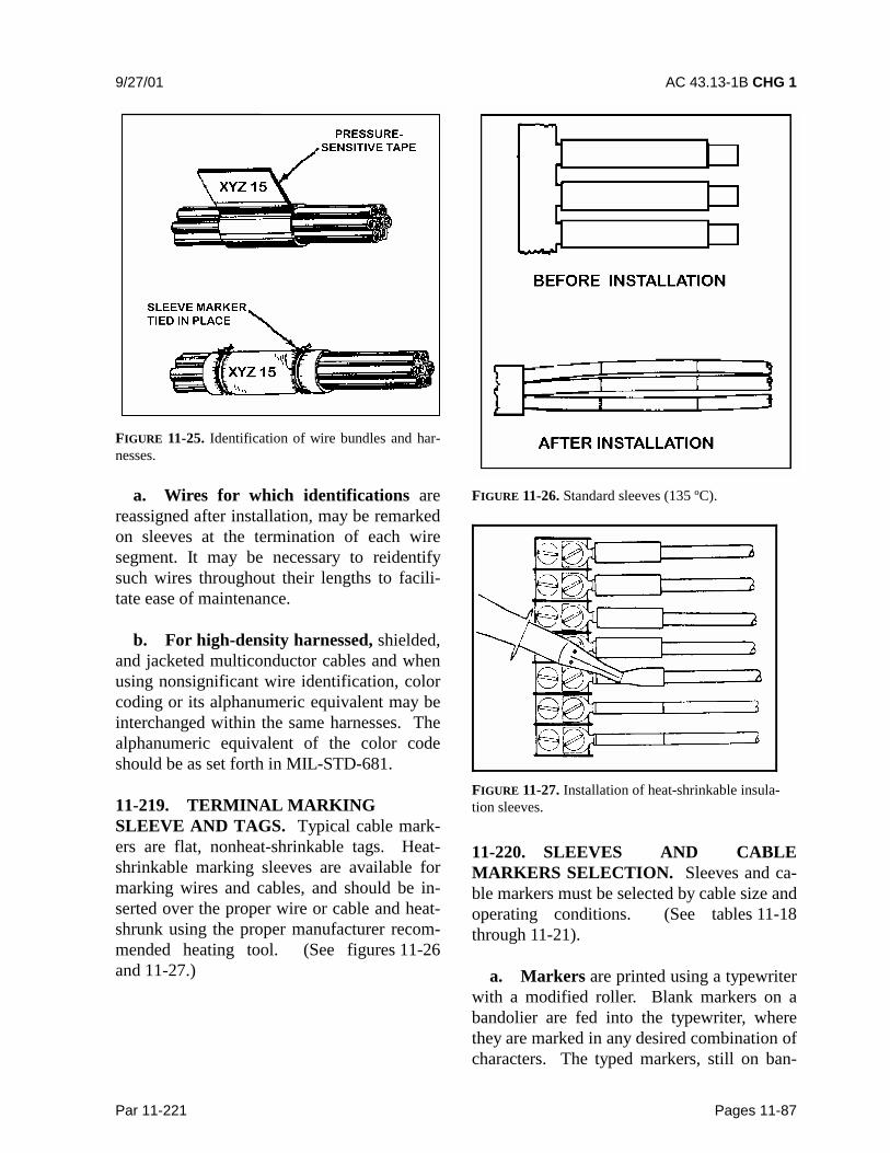
9/27/01 AC 43.13-1B CHG 1
Par 11-221 Pages 11-87
FIGURE 11-25. Identification of wire bundles and har-nesses.
a. Wires for which identifications arereassigned after installation, may be remarkedon sleeves at the termination of each wiresegment. It may be necessary to reidentifysuch wires throughout their lengths to facili-tate ease of maintenance.
b. For high-density harnessed, shielded,and jacketed multiconductor cables and whenusing nonsignificant wire identification, colorcoding or its alphanumeric equivalent may beinterchanged within the same harnesses. Thealphanumeric equivalent of the color codeshould be as set forth in MIL-STD-681.
11-219. TERMINAL MARKINGSLEEVE AND TAGS. Typical cable mark-ers are flat, nonheat-shrinkable tags. Heat-shrinkable marking sleeves are available formarking wires and cables, and should be in-serted over the proper wire or cable and heat-shrunk using the proper manufacturer recom-mended heating tool. (See figures 11-26and 11-27.)
FIGURE 11-26. Standard sleeves (135 ºC).
FIGURE 11-27. Installation of heat-shrinkable insula-tion sleeves.
11-220. SLEEVES AND CABLEMARKERS SELECTION. Sleeves and ca-ble markers must be selected by cable size andoperating conditions. (See tables 11-18through 11-21).
a. Markers are printed using a typewriterwith a modified roller. Blank markers on abandolier are fed into the typewriter, wherethey are marked in any desired combination ofcharacters. The typed markers, still on ban-
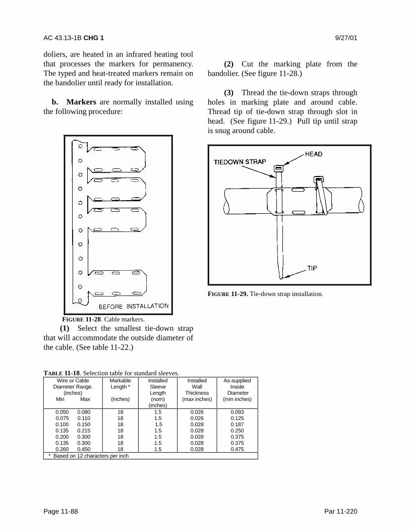
AC 43.13-1B CHG 1 9/27/01
Page 11-88 Par 11-220
doliers, are heated in an infrared heating toolthat processes the markers for permanency.The typed and heat-treated markers remain onthe bandolier until ready for installation.
b. Markers are normally installed usingthe following procedure:
FIGURE 11-28. Cable markers.(1) Select the smallest tie-down strap
that will accommodate the outside diameter ofthe cable. (See table 11-22.)
(2) Cut the marking plate from thebandolier. (See figure 11-28.)
(3) Thread the tie-down straps throughholes in marking plate and around cable.Thread tip of tie-down strap through slot inhead. (See figure 11-29.) Pull tip until strapis snug around cable.
FIGURE 11-29. Tie-down strap installation.
TABLE 11-18. Selection table for standard sleeves.Wire or Cable
Diameter Range.(inches)
Min Max
MarkableLength *
(inches)
InstalledSleeveLength(nom)
(inches)
InstalledWall
Thickness(max inches)
As-suppliedInside
Diameter(min inches)
0.050 0.0800.075 0.1100.100 0.1500.135 0.2150.200 0.3000.135 0.3000.260 0.450
18181818181818
1.51.5 1.51.51.51.51.5
0.0260.0260.0280.0280.0280.0280.028
0.0930.1250.1870.2500.3750.3750.475
* Based on 12 characters per inch

9/27/01 AC 43.13-1B CHG 1
Par 11-221 Pages 11-89
TABLE 11-19. Selection table for thin-wall sleeves.
Wire or CableDiameter Range
(inches)Min. Max.
MarkableLength *(inches)
InstalledSleeve
Length (nom)(inches)
Installed WallThickness
(max inches)
As-suppliedInside
Diameter(min inches)
0.035 0.0800.075 0.1100.100 0.1500.135 0.225
22222121
1.751.751.751.75
0.0200.0200.0210.021
0.0930.1250.1870.250
* Based on 12 characters per inch
TABLE 11-20. Selection table for high-temperature sleeves.
Wire or CableDiameter Range
(inches)Min. Max.
MarkableLength *
(inches)
InstalledSleeveLength(nom)
(inches)
InstalledWall
Thickness(max inches)
As-suppliedInside
Diameter (mininches)
0.035 0.0800.075 0.1100.100 0.1500.135 0.2150.200 0.3000.260 0.450
181818181818
1.51.51.51.51.51.5
0.0190.0160.0180.0180.0180.018
0.0930.1250.1870.2500.3750.475
* Based on 12 characters per inch
TABLE 11-21. Selection table for cable markers.
Cable DiameterRange
(inches)
Type of Cable Marker Number ofAttachment
Holes
Numberof Linesof Type
MarkerThickness
(nom)(inches)
0.25-0.500.25-0.50
0.25-0.500.50-up0.50-up0.50-up
0.50-up
0.50-up0.50-up
Standard, 135 °CHigh Temperature,200 °CNuclear, 135 °CStandard, 135 °CStandard, 135 °CHigh Temperature,200 °CHigh Temperature,200 °CNuclear, 135 °CNuclear, 135 °C
44
4464
6
46
22
2333
3
33
0.0250.020
0.0250.0250.0250.020
0.020
0.0250.025
TABLE 11-22. Plastic tie-down straps (MS3367, Type I, Class 1).
Cable Diameter(inches)
Min Max
Tie-down StrapMS3367-
Strap Identification * Installation Tool Tension Setting
1/16 5/81/16 1¼1/16 43/16 8
4-95-92-96-9
Miniature (MIN)Intermediate (INT)
Standard (STD)Heavy (HVY)
MS90387-1MS90387-1MS90387-1MS90387-2
2466
* The specified tool tension settings are for typical cable application. Settings less than or greater than those specified may be requiredfor special applications.
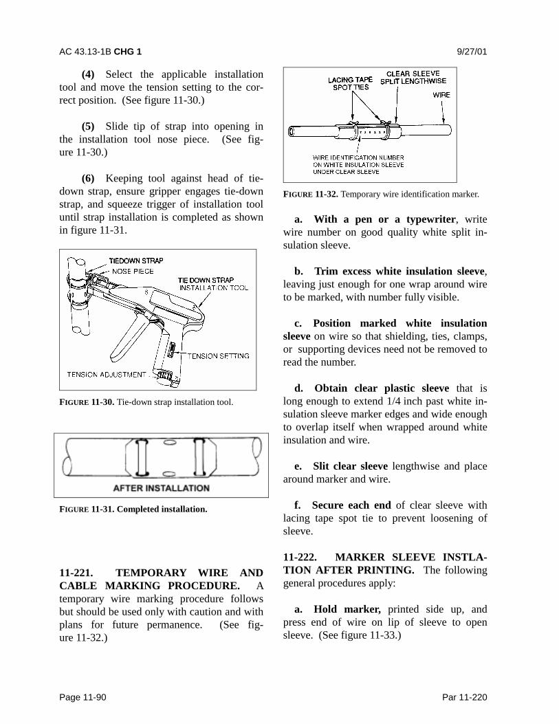
AC 43.13-1B CHG 1 9/27/01
Page 11-90 Par 11-220
(4) Select the applicable installationtool and move the tension setting to the cor-rect position. (See figure 11-30.)
(5) Slide tip of strap into opening inthe installation tool nose piece. (See fig-ure 11-30.)
(6) Keeping tool against head of tie-down strap, ensure gripper engages tie-downstrap, and squeeze trigger of installation tooluntil strap installation is completed as shownin figure 11-31.
FIGURE 11-30. Tie-down strap installation tool.
FIGURE 11-31. Completed installation.
11-221. TEMPORARY WIRE ANDCABLE MARKING PROCEDURE. Atemporary wire marking procedure followsbut should be used only with caution and withplans for future permanence. (See fig-ure 11-32.)
FIGURE 11-32. Temporary wire identification marker.
a. With a pen or a typewriter, writewire number on good quality white split in-sulation sleeve.
b. Trim excess white insulation sleeve,leaving just enough for one wrap around wireto be marked, with number fully visible.
c. Position marked white insulationsleeve on wire so that shielding, ties, clamps,or supporting devices need not be removed toread the number.
d. Obtain clear plastic sleeve that islong enough to extend 1/4 inch past white in-sulation sleeve marker edges and wide enoughto overlap itself when wrapped around whiteinsulation and wire.
e. Slit clear sleeve lengthwise and placearound marker and wire.
f. Secure each end of clear sleeve withlacing tape spot tie to prevent loosening ofsleeve.
11-222. MARKER SLEEVE INSTLA-TION AFTER PRINTING. The followinggeneral procedures apply:
a. Hold marker, printed side up, andpress end of wire on lip of sleeve to opensleeve. (See figure 11-33.)
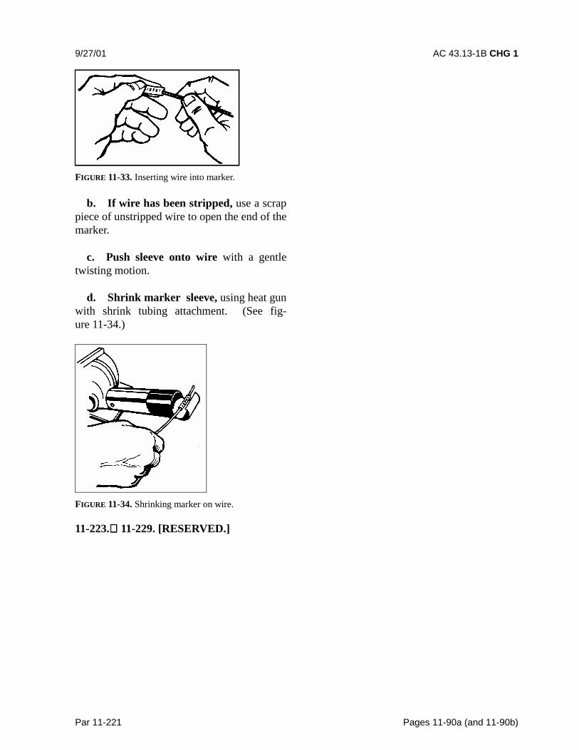
9/27/01 AC 43.13-1B CHG 1
Par 11-221 Pages 11-90a (and 11-90b)
FIGURE 11-33. Inserting wire into marker.
b. If wire has been stripped, use a scrappiece of unstripped wire to open the end of themarker.
c. Push sleeve onto wire with a gentletwisting motion.
d. Shrink marker sleeve, using heat gunwith shrink tubing attachment. (See fig-ure 11-34.)
FIGURE 11-34. Shrinking marker on wire.
11-223. 11-229. [RESERVED.]

9/27/01 AC 43.13-1B CHG 1
Par 11-230 Page 11-91
SECTION 17. CONNECTORS
11-230. GENERAL. There is a multitudeof types of connectors. Crimped contacts aregenerally used. Some of the more commonare the round cannon type, the rectangular,and the module blocks. Environmental-resistant connectors should be used in appli-cations subject to fluids, vibration, thermal,mechanical shock, and/or corrosive elements.When HIRF/Lightning protection is required,special attention should be given to the termi-nations of individual or overall shields. Thenumber and complexity of wiring systemshave resulted in an increased use of electricalconnectors. The proper choice and applica-tion of connectors is a significant part of theaircraft wiring system. Connectors must bekept to a minimum, selected, and installed toprovide the maximum degree of safety andreliability to the aircraft. For the installationof any particular connector assembly, thespecification of the manufacturer or the ap-propriate governing agency must be followed.
11-231. SELECTION. . Connectorsshould be selected to provide the maximumdegree of safety and reliability consideringelectrical and environmental requirements.Consider the size, weight, tooling, logistic,maintenance support, and compatibility withstandardization programs. For ease of assem-bly and maintenance, connectors usingcrimped contacts are generally chosen for allapplications except those requiring an her-metic seal. (Reference SAE ARP 1308, Pre-ferred Electrical Connectors For AerospaceVehicles and Associated Equipment.) A re-placement connector of the same basic typeand design as the connector it replaces shouldbe used. With a crimp type connector for anyelectrical connection, the proper insertion, orextraction tool must be used to install or re-move wires from such a connector. Refer tomanufacturer or aircraft instruction manual.After the connector is disconnected, inspect itfor loose soldered connections to prevent un-
intentional grounding. Connectors that aresusceptible to corrosion difficulties may betreated with a chemically inert waterproofjelly.
11-232. TYPES OF CONNECTORS.Connectors must be identified by an originalidentification number derived from MILSpecification (MS) or OAM specification.Figure 11-35 provides some examples of MSconnector types. Several different types areshown in figures 11-36 and 11-37.
a. Environmental Classes. Environ-ment-resistant connectors are used in applica-tions where they will probably be subjected tofluids, vibration, thermal, mechanical shock,corrosive elements, etc. Firewall class con-nectors incorporating these same featuresshould, in addition, be able to prevent thepenetration of the fire through the aircraftfirewall connector opening and continue tofunction without failure for a specified periodof time when exposed to fire. Hermetic con-nectors provide a pressure seal for maintain-ing pressurized areas. When EMI/RFI pro-tection is required, special attention should begiven to the termination of individual andoverall shields. Backshell adapters designedfor shield termination, connectors with con-ductive finishes, and EMI grounding fingersare available for this purpose.
b. Rectangular Connectors. The rec-tangular connectors are typically used in ap-plications where a very large number of cir-cuits are accommodated in a single matedpair. They are available with a great varietyof contacts, which can include a mix of stan-dard, coaxial, and large power types. Cou-pling is accomplished by various means.Smaller types are secured with screws whichhold their flanges together. Larger ones haveintegral guide pins that ensure correct align-ment, or jackscrews that both align and lock
AC 43.13-1B CHG 1 9/27/01
Page 11-91a Par 11-232
the connectors. Rack and panel connectorsuse integral or rack-mounted pins for align-ment and box mounting hardware for cou-plings.
c. Module Blocks. These junctions ac-cept crimped contacts similar to those onconnectors. Some use internal busing to pro-vide a variety of circuit arrangements. Theyare useful where a number of wires are con-nected for power or signal distribution.
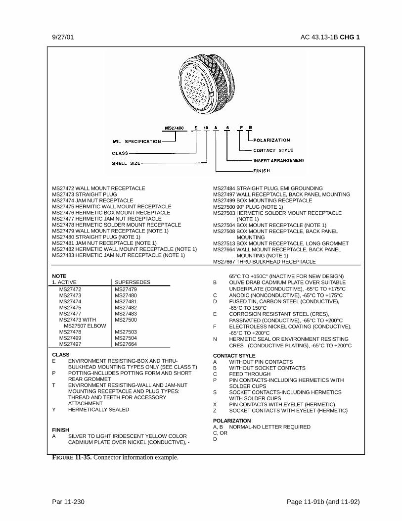
9/27/01 AC 43.13-1B CHG 1
Par 11-230 Page 11-91b (and 11-92)
MS27472 WALL MOUNT RECEPTACLEMS27473 STRAIGHT PLUGMS27474 JAM NUT RECEPTACLEMS27475 HERMITIC WALL MOUNT RECEPTACLEMS27476 HERMETIC BOX MOUNT RECEPTACLEMS27477 HERMETIC JAM NUT RECEPTACLEMS27478 HERMETIC SOLDER MOUNT RECEPTACLEMS27479 WALL MOUNT RECEPTACLE (NOTE 1)MS27480 STRAIGHT PLUG (NOTE 1)MS27481 JAM NUT RECEPTACLE (NOTE 1)MS27482 HERMETIC WALL MOUNT RECEPTACLE (NOTE 1)MS27483 HERMETIC JAM NUT RECEPTACLE (NOTE 1)
MS27484 STRAIGHT PLUG, EMI GROUNDINGMS27497 WALL RECEPTACLE, BACK PANEL MOUNTINGMS27499 BOX MOUNTING RECEPTACLEMS27500 90° PLUG (NOTE 1)MS27503 HERMETIC SOLDER MOUNT RECEPTACLE
(NOTE 1)MS27504 BOX MOUNT RECEPTACLE (NOTE 1)MS27508 BOX MOUNT RECEPTACLE, BACK PANEL
MOUNTINGMS27513 BOX MOUNT RECEPTACLE, LONG GROMMETMS27664 WALL MOUNT RECEPTACLE, BACK PANEL
MOUNTING (NOTE 1)MS27667 THRU-BULKHEAD RECEPTACLE
NOTE1. ACTIVE SUPERSEDES
MS27472 MS27479MS27473 MS27480MS27474 MS27481MS27475 MS27482MS27477 MS27483MS27473 WITH MS27500
MS27507 ELBOWMS27478 MS27503MS27499 MS27504MS27497 MS27664
CLASSE ENVIRONMENT RESISTING-BOX AND THRU-
BULKHEAD MOUNTING TYPES ONLY (SEE CLASS T)P POTTING-INCLUDES POTTING FORM AND SHORT
REAR GROMMETT ENVIRONMENT RESISTING-WALL AND JAM-NUT
MOUNTING RECEPTACLE AND PLUG TYPES: THREAD AND TEETH FOR ACCESSORYATTACHMENT
Y HERMETICALLY SEALED
FINISHA SILVER TO LIGHT IRIDESCENT YELLOW COLOR
CADMIUM PLATE OVER NICKEL (CONDUCTIVE), -
65°C TO +150C° (INACTIVE FOR NEW DESIGN)B OLIVE DRAB CADMIUM PLATE OVER SUITABLE
UNDERPLATE (CONDUCTIVE), -65°C TO +175°CC ANODIC (NONCONDUCTIVE), -65°C TO +175°CD FUSED TIN, CARBON STEEL (CONDUCTIVE),
-65°C TO 150°CE CORROSION RESISTANT STEEL (CRES),
PASSIVATED (CONDUCTIVE), -65°C TO +200°CF ELECTROLESS NICKEL COATING (CONDUCTIVE),
-65°C TO +200°CN HERMETIC SEAL OR ENVIRONMENT RESISTING
CRES (CONDUCTIVE PLATING), -65°C TO +200°C
CONTACT STYLEA WITHOUT PIN CONTACTSB WITHOUT SOCKET CONTACTSC FEED THROUGHP PIN CONTACTS-INCLUDING HERMETICS WITH
SOLDER CUPSS SOCKET CONTACTS-INCLUDING HERMETICS
WITH SOLDER CUPSX PIN CONTACTS WITH EYELET (HERMETIC)Z SOCKET CONTACTS WITH EYELET (HERMETIC)
POLARIZATIONA, B NORMAL-NO LETTER REQUIREDC, ORD
FIGURE 11-35. Connector information example.
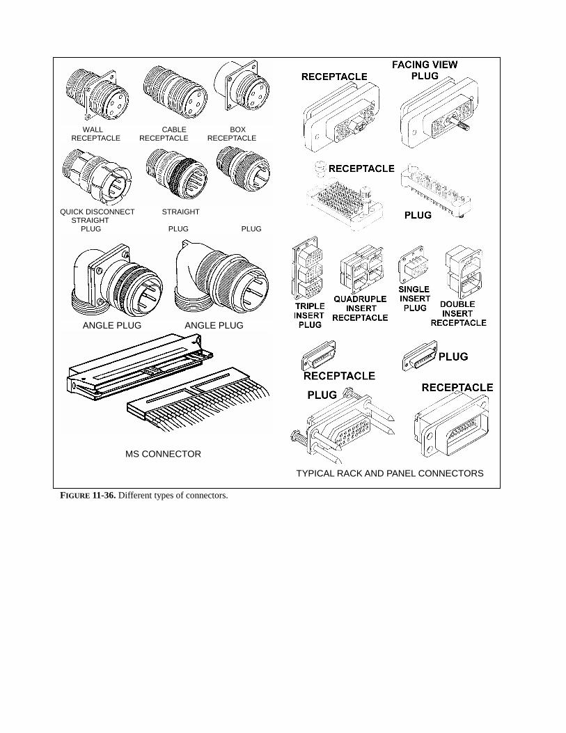
WALL CABLE BOXRECEPTACLE RECEPTACLE RECEPTACLE
QUICK DISCONNECT STRAIGHT STRAIGHT
PLUG PLUG PLUG
ANGLE PLUG ANGLE PLUG
MS CONNECTOR
TYPICAL RACK AND PANEL CONNECTORS
FIGURE 11-36. Different types of connectors.
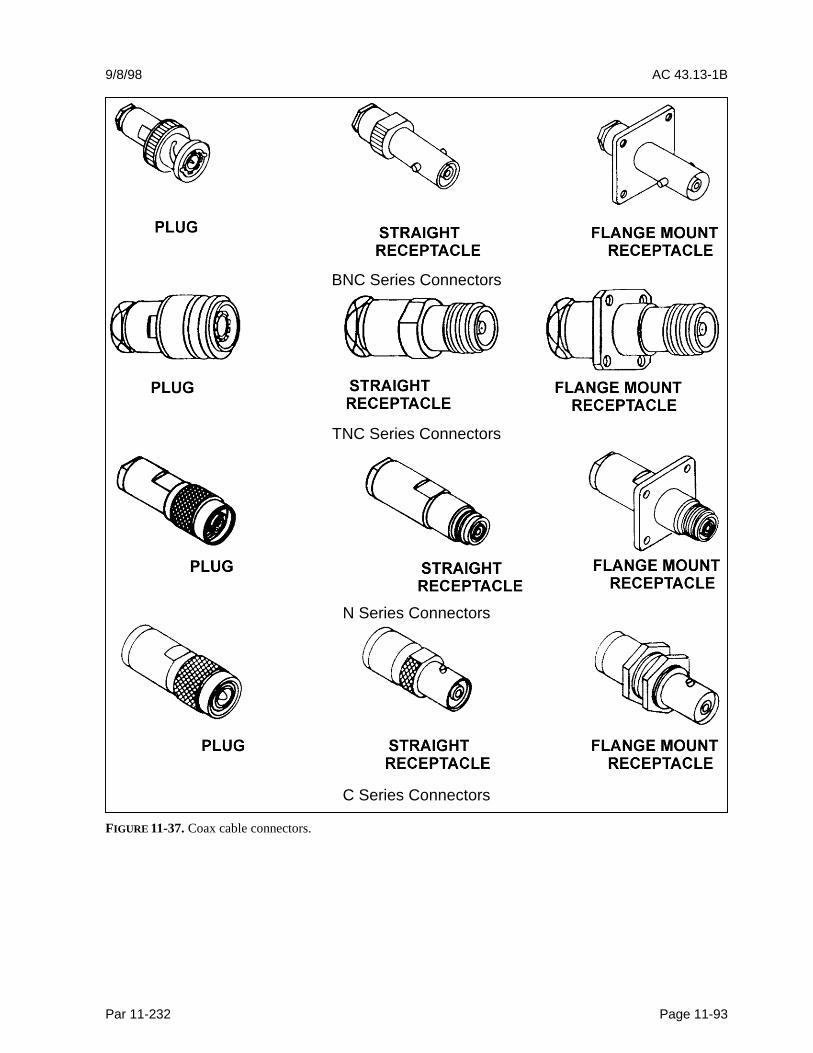
9/8/98 AC 43.13-1B
Par 11-232 Page 11-93
BNC Series Connectors
TNC Series Connectors
N Series Connectors
C Series Connectors
FIGURE 11-37. Coax cable connectors.
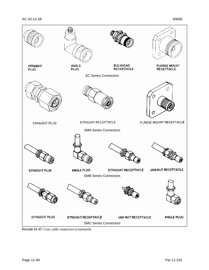
AC 43.13-1B 9/8/98
Page 11-94 Par 11-232
SC Series Connectors
SMA Series Connectors
SMB Series Connectors
SMC Series Connectors
FIGURE 11-37. Coax cable connectors (continued).

9/8/98 AC 43.13-1B
Par 11-232 Page 11-95
FIGURE 11-37. Coax cable connectors (continued).
When used as grounding modules, they saveand reduce hardware installation on the air-craft. Standardized modules are available withwire end grommet seals for environmental ap-plications and are track-mounted. Functionmodule blocks are used to provide an easilywired package for environment-resistantmounting of small resistors, diodes, filters, andsuppression networks. In-line terminal junc-tions are sometimes used in lieu of a connectorwhen only a few wires are terminated andwhen the ability to disconnect the wires is de-sired. The in-line terminal junction is envi-ronment-resistant. The terminal junctionsplice is small and may be tied to the surfaceof a wire bundle when approved by the OAM.
11-233. VOLTAGE AND CURRENTRATING. Selected connectors must be ratedfor continuous operation under the maximumcombination of ambient temperature and cir-cuit current load. Hermetic connectors andconnectors used in circuit applications involv-ing high-inrush currents should be derated. Itis good engineering practice to conduct pre-liminary testing in any situation where theconnector is to operate with most or all of itscontacts at maximum rated current load. Whenwiring is operating with a high conductor tem-perature near its rated temperature, connectorcontact sizes should be suitably rated for thecircuit load. This may require an increase inwire size also. Voltage derating is requiredwhen connectors are used at high altitude in
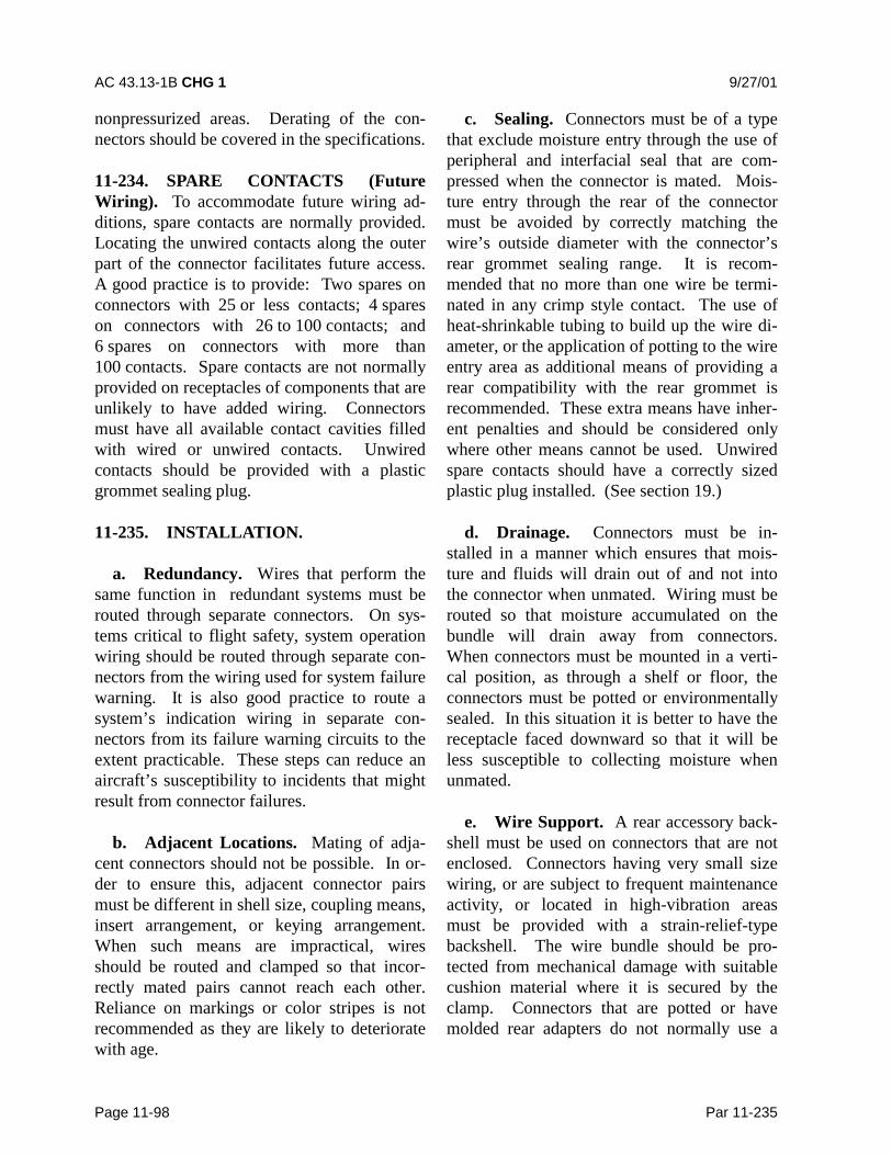
AC 43.13-1B CHG 1 9/27/01
Page 11-98 Par 11-235
nonpressurized areas. Derating of the con-nectors should be covered in the specifications.
11-234. SPARE CONTACTS (FutureWiring). To accommodate future wiring ad-ditions, spare contacts are normally provided.Locating the unwired contacts along the outerpart of the connector facilitates future access.A good practice is to provide: Two spares onconnectors with 25 or less contacts; 4 spareson connectors with 26 to 100 contacts; and6 spares on connectors with more than100 contacts. Spare contacts are not normallyprovided on receptacles of components that areunlikely to have added wiring. Connectorsmust have all available contact cavities filledwith wired or unwired contacts. Unwiredcontacts should be provided with a plasticgrommet sealing plug.
11-235. INSTALLATION.
a. Redundancy. Wires that perform thesame function in redundant systems must berouted through separate connectors. On sys-tems critical to flight safety, system operationwiring should be routed through separate con-nectors from the wiring used for system failurewarning. It is also good practice to route asystem’s indication wiring in separate con-nectors from its failure warning circuits to theextent practicable. These steps can reduce anaircraft’s susceptibility to incidents that mightresult from connector failures.
b. Adjacent Locations. Mating of adja-cent connectors should not be possible. In or-der to ensure this, adjacent connector pairsmust be different in shell size, coupling means,insert arrangement, or keying arrangement.When such means are impractical, wiresshould be routed and clamped so that incor-rectly mated pairs cannot reach each other.Reliance on markings or color stripes is notrecommended as they are likely to deterioratewith age.
c. Sealing. Connectors must be of a typethat exclude moisture entry through the use ofperipheral and interfacial seal that are com-pressed when the connector is mated. Mois-ture entry through the rear of the connectormust be avoided by correctly matching thewire’s outside diameter with the connector’srear grommet sealing range. It is recom-mended that no more than one wire be termi-nated in any crimp style contact. The use ofheat-shrinkable tubing to build up the wire di-ameter, or the application of potting to the wireentry area as additional means of providing arear compatibility with the rear grommet isrecommended. These extra means have inher-ent penalties and should be considered onlywhere other means cannot be used. Unwiredspare contacts should have a correctly sizedplastic plug installed. (See section 19.)
d. Drainage. Connectors must be in-stalled in a manner which ensures that mois-ture and fluids will drain out of and not intothe connector when unmated. Wiring must berouted so that moisture accumulated on thebundle will drain away from connectors.When connectors must be mounted in a verti-cal position, as through a shelf or floor, theconnectors must be potted or environmentallysealed. In this situation it is better to have thereceptacle faced downward so that it will beless susceptible to collecting moisture whenunmated.
e. Wire Support. A rear accessory back-shell must be used on connectors that are notenclosed. Connectors having very small sizewiring, or are subject to frequent maintenanceactivity, or located in high-vibration areasmust be provided with a strain-relief-typebackshell. The wire bundle should be pro-tected from mechanical damage with suitablecushion material where it is secured by theclamp. Connectors that are potted or havemolded rear adapters do not normally use a
9/8/98 AC 43.13-1B
Par 11-239 Page 11-99 (and 11-96)
separate strain relief accessory. Strain reliefclamps should not impart tension on wiresbetween the clamp and contact.
f. Slack. Sufficient wire length must beprovided at connectors to ensure a proper driploop and that there is no strain on terminationafter a complete replacement of the connectorand its contacts.
g. Identification. Each connector shouldhave a reference identification that is legiblethroughout the expected life of the aircraft.
11-236. FEED-THROUGH BULKHEADWIRE PROTECTION. Feed-through bush-ing protection should be given to wire bundleswhich pass through bulkheads, frames, andother similar structure. Feed-through bushingsof hard dielectric material are satisfactory. Theuse of split plastic grommets (nylon) is rec-ommended in lieu of rubber grommets in areassubject to fluids, since they eliminate the un-satisfactory features of rubber grommets andare resistant to fluids usually encountered inaircraft.
11-237. SPECIAL PURPOSE CONNEC-TOR. Many special-purpose connectors havebeen designed for use in aircraft applications,such as: subminiature connector, rectangularshell connector, connectors with short bodyshells, or connector of split-shell constructionused in applications where potting is required.Make every attempt to identify the connectorpart number from the maintenance manual oractual part, and the manufacturer’s instructionused for servicing.
11-238. POTTING COMPOUNDS. Manytypes of potting compounds, both commercialand per military specifications, are availableand offer various characteristics for differentapplications. Carefully consider the charac-teristics desired to ensure the use of the proper
compound. Preparation and storage of pottingmaterials should receive special attention.Careful inspection and handling during allstages of the connector fabrication until thepotting compound has fully cured is recom-mended. Potting compounds selected must notrevert to liquid or become gummy or stickydue to high humidity or contact with chemicalfluids.
a. Potting compounds meeting Specifi-cation MIL-S-8516 are prepared in ready-to-use tube-type dispensers and in the unmixedstate, consisting of the base compound and anaccelerator packed in paired containers. Toobtain the proper results, it is important thatthe manufacturer’s instructions be closely fol-lowed.
b. Potting compounds normally cure attemperatures of 70 °F to 76 °F. If the mixedcompound is not used at once, the working potlife (normally 90 minutes) can be prolonged bystoring in a deep freeze at -20 °F for a maxi-mum of 36 hours. The time factor starts fromthe instant the accelerator is added to the basecompound and includes the time expendedduring the mixing and application processes.
c. Mixed compounds that are not to beused immediately should be cooled and thawedquickly to avoid wasting the short workinglife. Chilled compounds should be thawed byblowing compressed air over the outside of thecontainer. Normally the compound will beready for use in 5 to 10 minutes.
CAUTION: Do not use heat or blowcompressed air into the containerwhen restoring the compound to theworking temperature.
11-239. POTTING CONNECTORS.Connectors that have been potted primarily of-fer protection against concentration of
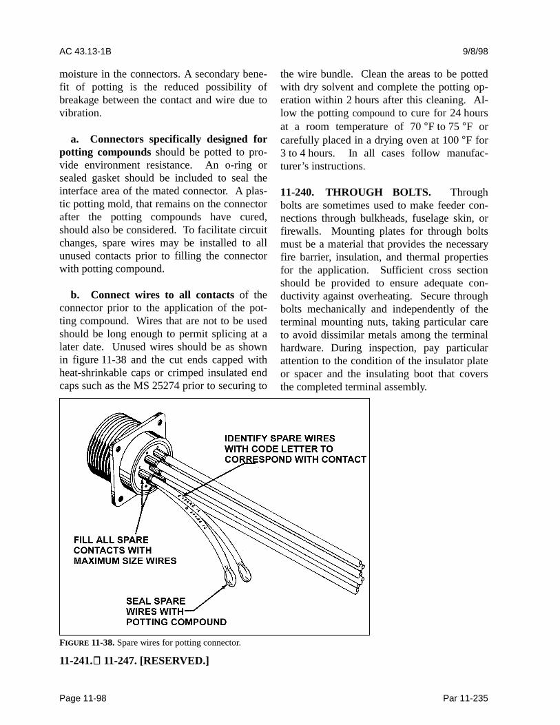
AC 43.13-1B 9/8/98
Page 11-98 Par 11-235
moisture in the connectors. A secondary bene-fit of potting is the reduced possibility ofbreakage between the contact and wire due tovibration.
a. Connectors specifically designed forpotting compounds should be potted to pro-vide environment resistance. An o-ring orsealed gasket should be included to seal theinterface area of the mated connector. A plas-tic potting mold, that remains on the connectorafter the potting compounds have cured,should also be considered. To facilitate circuitchanges, spare wires may be installed to allunused contacts prior to filling the connectorwith potting compound.
b. Connect wires to all contacts of theconnector prior to the application of the pot-ting compound. Wires that are not to be usedshould be long enough to permit splicing at alater date. Unused wires should be as shownin figure 11-38 and the cut ends capped withheat-shrinkable caps or crimped insulated endcaps such as the MS 25274 prior to securing to
the wire bundle. Clean the areas to be pottedwith dry solvent and complete the potting op-eration within 2 hours after this cleaning. Al-low the potting compound to cure for 24 hoursat a room temperature of 70 °F to 75 °F orcarefully placed in a drying oven at 100 °F for3 to 4 hours. In all cases follow manufac-turer’s instructions.
11-240. THROUGH BOLTS. Throughbolts are sometimes used to make feeder con-nections through bulkheads, fuselage skin, orfirewalls. Mounting plates for through boltsmust be a material that provides the necessaryfire barrier, insulation, and thermal propertiesfor the application. Sufficient cross sectionshould be provided to ensure adequate con-ductivity against overheating. Secure throughbolts mechanically and independently of theterminal mounting nuts, taking particular careto avoid dissimilar metals among the terminalhardware. During inspection, pay particularattention to the condition of the insulator plateor spacer and the insulating boot that coversthe completed terminal assembly.
FIGURE 11-38. Spare wires for potting connector.
11-241. 11-247. [RESERVED.]

9/8/98 AC 43.13-1B
Par 11-239 Page 11-101
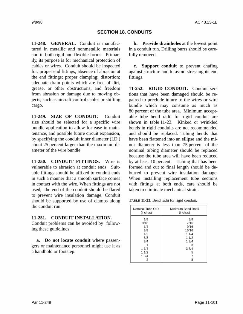
9/8/98 AC 43.13-1B
Par 11-248 Page 11-101
SECTION 18. CONDUITS
11-248. GENERAL. Conduit is manufac-tured in metallic and nonmetallic materialsand in both rigid and flexible forms. Primar-ily, its purpose is for mechanical protection ofcables or wires. Conduit should be inspectedfor: proper end fittings; absence of abrasion atthe end fittings; proper clamping; distortion;adequate drain points which are free of dirt,grease, or other obstructions; and freedomfrom abrasion or damage due to moving ob-jects, such as aircraft control cables or shiftingcargo. 11-249. SIZE OF CONDUIT. Conduitsize should be selected for a specific wirebundle application to allow for ease in main-tenance, and possible future circuit expansion,by specifying the conduit inner diameter (I.D.)about 25 percent larger than the maximum di-ameter of the wire bundle.
11-250. CONDUIT FITTINGS. Wire isvulnerable to abrasion at conduit ends. Suit-able fittings should be affixed to conduit endsin such a manner that a smooth surface comesin contact with the wire. When fittings are notused, the end of the conduit should be flaredto prevent wire insulation damage. Conduitshould be supported by use of clamps alongthe conduit run.
11-251. CONDUIT INSTALLATION.Conduit problems can be avoided by follow-ing these guidelines:
a. Do not locate conduit where passen-gers or maintenance personnel might use it asa handhold or footstep.
b. Provide drainholes at the lowest pointin a conduit run. Drilling burrs should be care-fully removed.
c. Support conduit to prevent chafingagainst structure and to avoid stressing its endfittings.
11-252. RIGID CONDUIT. Conduit sec-tions that have been damaged should be re-paired to preclude injury to the wires or wirebundle which may consume as much as80 percent of the tube area. Minimum accept-able tube bend radii for rigid conduit areshown in table 11-23. Kinked or wrinkledbends in rigid conduits are not recommendedand should be replaced. Tubing bends thathave been flattened into an ellipse and the mi-nor diameter is less than 75 percent of thenominal tubing diameter should be replacedbecause the tube area will have been reducedby at least 10 percent. Tubing that has beenformed and cut to final length should be de-burred to prevent wire insulation damage.When installing replacement tube sectionswith fittings at both ends, care should betaken to eliminate mechanical strain.
TABLE 11-23. Bend radii for rigid conduit.
Nominal Tube O.D.(inches)
Minimum Bend Radii(inches)
1/83/161/43/81/25/83/4
11 1/41 1/21 3/4
2
3/87/169/16
15/161 1/41 1/21 3/4
33 3/4
578
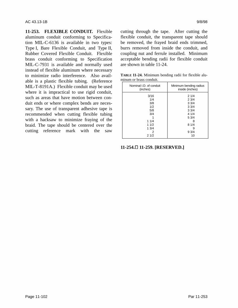
AC 43.13-1B 9/8/98
Page 11-102 Par 11-253
11-253. FLEXIBLE CONDUIT. Flexiblealuminum conduit conforming to Specifica-tion MIL-C-6136 is available in two types:Type I, Bare Flexible Conduit, and Type II,Rubber Covered Flexible Conduit. Flexiblebrass conduit conforming to SpecificationMIL-C-7931 is available and normally usedinstead of flexible aluminum where necessaryto minimize radio interference. Also avail-able is a plastic flexible tubing. (ReferenceMIL-T-8191A.) Flexible conduit may be usedwhere it is impractical to use rigid conduit,such as areas that have motion between con-duit ends or where complex bends are neces-sary. The use of transparent adhesive tape isrecommended when cutting flexible tubingwith a hacksaw to minimize fraying of thebraid. The tape should be centered over thecutting reference mark with the saw
cutting through the tape. After cutting theflexible conduit, the transparent tape shouldbe removed, the frayed braid ends trimmed,burrs removed from inside the conduit, andcoupling nut and ferrule installed. Minimumacceptable bending radii for flexible conduitare shown in table 11-24.
TABLE 11-24. Minimum bending radii for flexible alu-minum or brass conduit.
Nominal I.D. of conduit(inches)
Minimum bending radiusinside (inches)
3/161/43/81/25/83/4
11 1/41 1/21 3/4
22 1/2
2 1/42 3/43 3/43 3/43 3/44 1/45 3/4
88 1/4
99 3/4
10
11-254. 11-259. [RESERVED.]
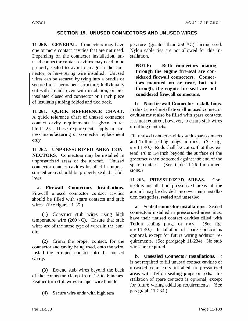
9/27/01 AC 43.13-1B CHG 1
Par 11-260 Page 11-103
SECTION 19. UNUSED CONNECTORS AND UNUSED WIRES
11-260. GENERAL. Connectors may haveone or more contact cavities that are not used.Depending on the connector installation, un-used connector contact cavities may need to beproperly sealed to avoid damage to the con-nector, or have string wire installed. Unusedwires can be secured by tying into a bundle orsecured to a permanent structure; individuallycut with strands even with insulation; or pre-insulated closed end connector or 1 inch pieceof insulating tubing folded and tied back.
11-261. QUICK REFERENCE CHART.A quick reference chart of unused connectorcontact cavity requirements is given in ta-ble 11-25. These requirements apply to har-ness manufacturing or connector replacementonly.
11-262. UNPRESSURIZED AREA CON-NECTORS. Connectors may be installed inunpressurized areas of the aircraft. Unusedconnector contact cavities installed in unpres-surized areas should be properly sealed as fol-lows:
a. Firewall Connectors Installations.Firewall unused connector contact cavitiesshould be filled with spare contacts and stubwires. (See figure 11-39.)
(1) Construct stub wires using hightemperature wire (260 ºC). Ensure that stubwires are of the same type of wires in the bun-dle.
(2) Crimp the proper contact, for theconnector and cavity being used, onto the wire.Install the crimped contact into the unusedcavity.
(3) Extend stub wires beyond the backof the connector clamp from 1.5 to 6 inches.Feather trim stub wires to taper wire bundle.
(4) Secure wire ends with high tem
perature (greater than 250 ºC) lacing cord.Nylon cable ties are not allowed for this in-stallation.
NOTE: Both connectors matingthrough the engine fire-seal are con-sidered firewall connectors. Connec-tors mounted on or near, but notthrough, the engine fire-seal are notconsidered firewall connectors.
b. Non-firewall Connector Installations.In this type of installation all unused connectorcavities must also be filled with spare contacts.It is not required, however, to crimp stub wireson filling contacts.
Fill unused contact cavities with spare contactsand Teflon sealing plugs or rods. (See fig-ure 11-40.) Rods shall be cut so that they ex-tend 1/8 to 1/4 inch beyond the surface of thegrommet when bottomed against the end of thespare contact. (See table 11-26 for dimen-sions.)
11-263. PRESSURIZED AREAS. Con-nectors installed in pressurized areas of theaircraft may be divided into two main installa-tion categories, sealed and unsealed.
a. Sealed connector installations. Sealedconnectors installed in pressurized areas musthave their unused contact cavities filled withTeflon sealing plugs or rods. (See fig-ure 11-40.) Installation of spare contacts isoptional, except for future wiring addition re-quirements. (See paragraph 11-234). No stubwires are required.
b. Unsealed Connector Installations. Itis not required to fill unused contact cavities ofunsealed connectors installed in pressurizedareas with Teflon sealing plugs or rods. In-stallation of spare contacts is optional, exceptfor future wiring addition requirements. (Seeparagraph 11-234.)
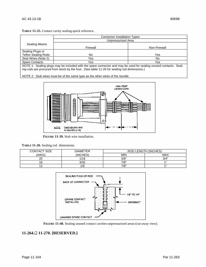
AC 43.13-1B 9/8/98
Page 11-104 Par 11-263
TABLE 11-25. Contact cavity sealing-quick reference.
Connector Installation TypesUnpressurized Area
Sealing MeansFirewall Non-Firewall
Sealing Plugs orTeflon Sealing Rods No YesStub Wires (Note 2) Yes NoSpare Contacts Yes YesNOTE 1: Sealing plugs may be included with the spare connector and may be used for sealing unused contacts. Seal-ing rods are procured from stock by the foot. (See table 11-26 for sealing rod dimensions.)
NOTE 2: Stub wires must be of the same type as the other wires of the bundle.
FIGURE 11-39. Stub wire installation.
TABLE 11-26. Sealing rod dimensions.
CONTACT SIZE DIAMETER ROD LENGTH (INCHES)(AWG) (INCHES) MIN MAX
20 1/16 5/8” 3/4”16 3/32 7/8” 1”12 1/8 7/8” 1”
FIGURE 11-40. Sealing unused contact cavities-unpressurized areas-(cut-away view).
11-264. 11-270. [RESERVED.]

9/8/98 AC 43.13-1B
Par 11-271 Page 11-105
SECTION 20. ELECTRICAL AND ELECTRONIC SYMBOLS
11-271. GENERAL. The electrical andelectronic symbols shown here are those thatare likely to be encountered by the aviationmaintenance technician. They are in accor-dance with ANSI-Y32.2-1975.
11-272. SYMBOLS. Only those symbolsassociated with aircraft electrical and elec-tronic wiring have been listed in general. Re-fer to ANSI-Y32.2-1975 for more specificdetail on each symbol.
TABLE 11-27. Electronic/Electrical Symbols.
Symbol Meaning
Adjustability Variability
Radiation Indicators
Physical State Recognition
Test-Point Recognition
Polarity Markings
Direction of Flow of Power, Signal, orInformation
Kind of Current
Envelope Enclosure
Shield Shielding
Special Connector or Cable Indicator

AC 43.13-1B 9/8/98
Page 11-106 Par 11-272
TABLE 11-27. Electronic/Electrical Symbols (continued).
Symbol Meaning
Resistor
Capacitor
Antenna
Battery
Thermal Element ThermomechanicalTransducer
Thermocouple
Spark Gap Ignitor Gap
Continuous Loop Fire Detector (Tem-perature Sensor)
Ignitor Plug
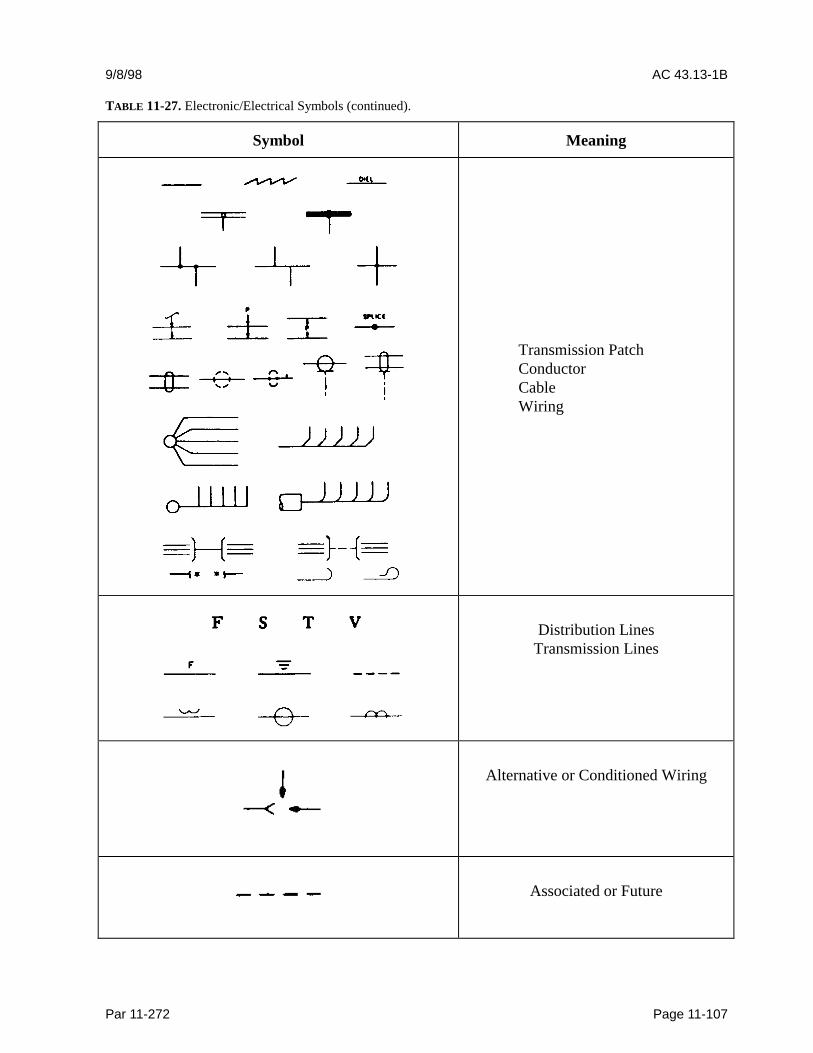
9/8/98 AC 43.13-1B
Par 11-272 Page 11-107
TABLE 11-27. Electronic/Electrical Symbols (continued).
Symbol Meaning
Transmission PatchConductorCableWiring
Distribution LinesTransmission Lines
Alternative or Conditioned Wiring
Associated or Future
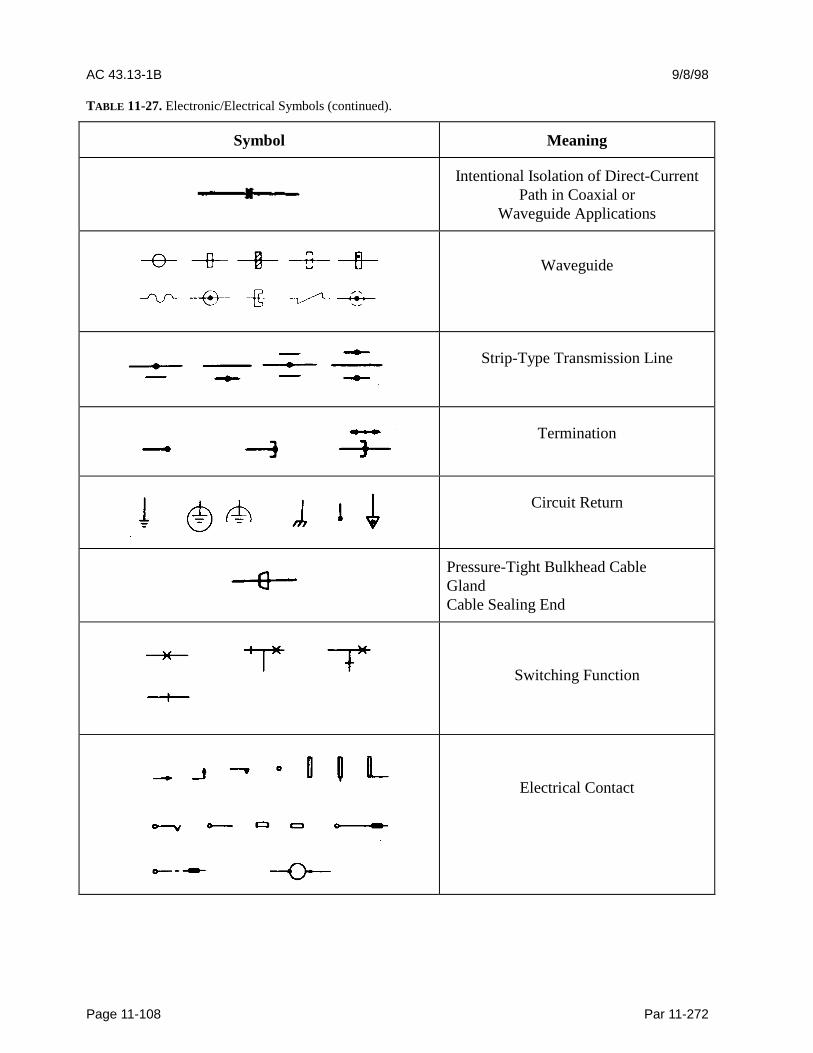
AC 43.13-1B 9/8/98
Page 11-108 Par 11-272
TABLE 11-27. Electronic/Electrical Symbols (continued).
Symbol Meaning
Intentional Isolation of Direct-CurrentPath in Coaxial or
Waveguide Applications
Waveguide
Strip-Type Transmission Line
Termination
Circuit Return
Pressure-Tight Bulkhead CableGlandCable Sealing End
Switching Function
Electrical Contact
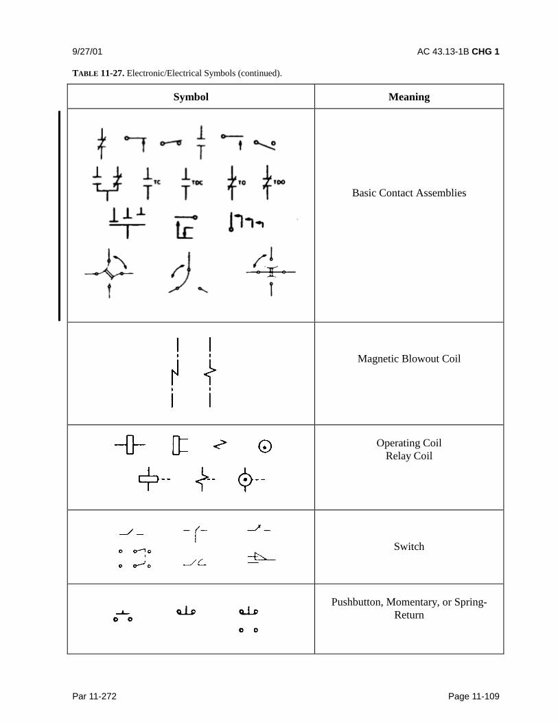
9/27/01 AC 43.13-1B CHG 1
Par 11-272 Page 11-109
TABLE 11-27. Electronic/Electrical Symbols (continued).
Symbol Meaning
Basic Contact Assemblies
Magnetic Blowout Coil
Operating CoilRelay Coil
Switch
Pushbutton, Momentary, or Spring-Return
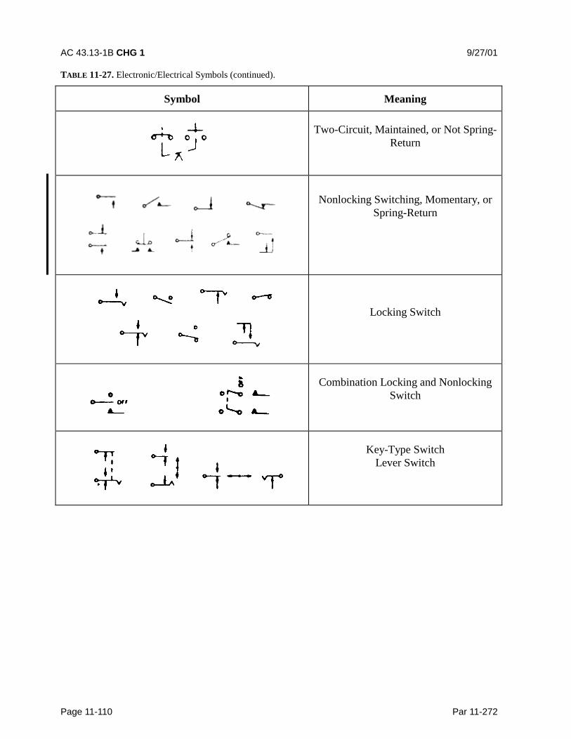
AC 43.13-1B CHG 1 9/27/01
Page 11-110 Par 11-272
TABLE 11-27. Electronic/Electrical Symbols (continued).
Symbol Meaning
Two-Circuit, Maintained, or Not Spring-Return
Nonlocking Switching, Momentary, orSpring-Return
Locking Switch
Combination Locking and NonlockingSwitch
Key-Type SwitchLever Switch

9/8/98 AC 43.13-1B
Par 11-272 Page 11-111
TABLE 11-27. Electronic/Electrical Symbols (continued).
Symbol Meaning
Selector or Multiposition Switch
Safety Interlock
Limit SwitchSensitive Switch
Switches with Time-Delay Feature
Flow-Actuated Switch
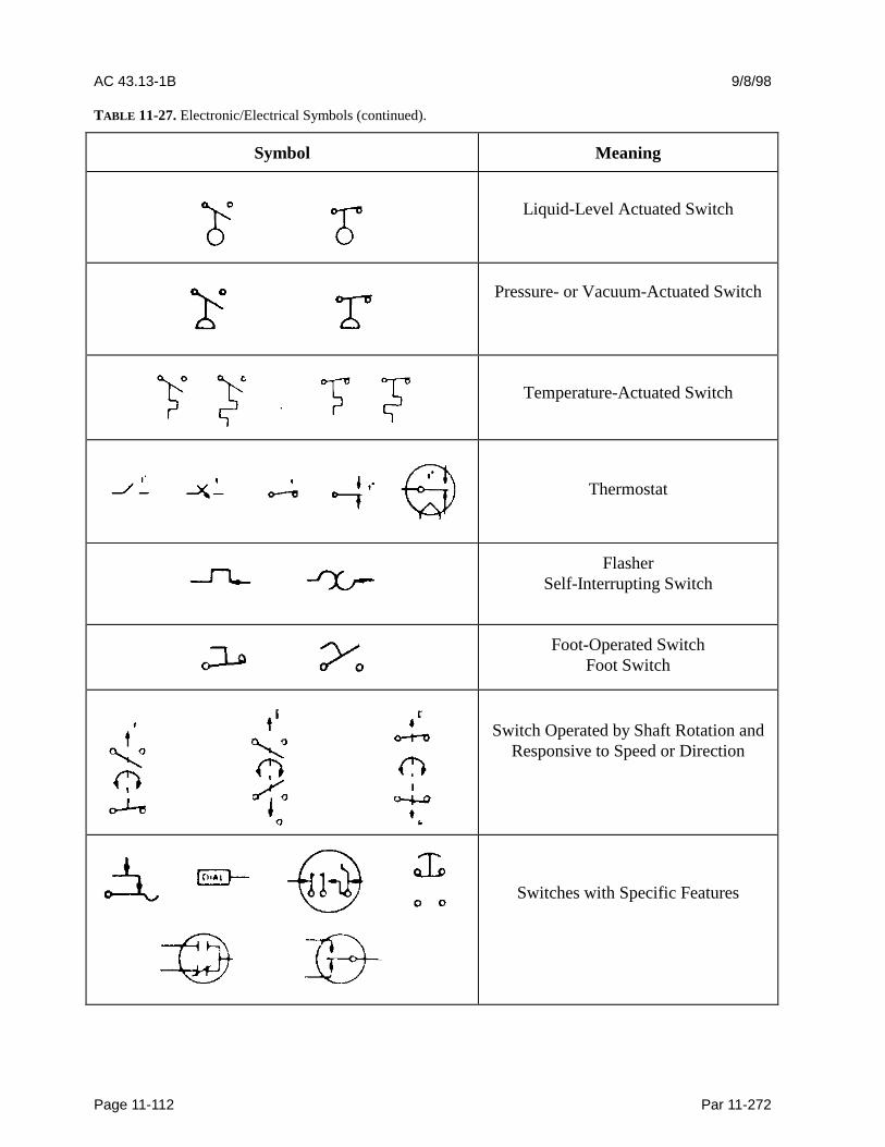
AC 43.13-1B 9/8/98
Page 11-112 Par 11-272
TABLE 11-27. Electronic/Electrical Symbols (continued).
Symbol Meaning
Liquid-Level Actuated Switch
Pressure- or Vacuum-Actuated Switch
Temperature-Actuated Switch
Thermostat
FlasherSelf-Interrupting Switch
Foot-Operated SwitchFoot Switch
Switch Operated by Shaft Rotation andResponsive to Speed or Direction
Switches with Specific Features
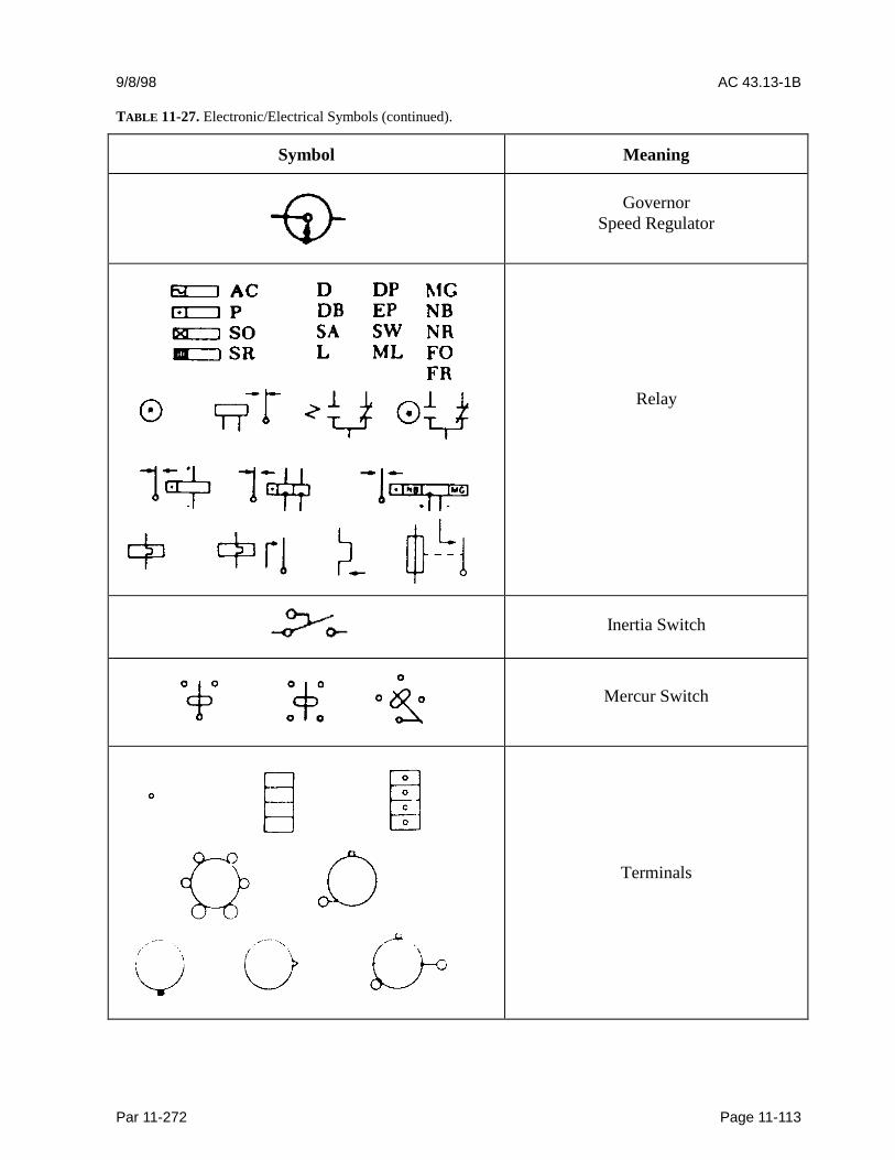
9/8/98 AC 43.13-1B
Par 11-272 Page 11-113
TABLE 11-27. Electronic/Electrical Symbols (continued).
Symbol Meaning
GovernorSpeed Regulator
Relay
Inertia Switch
Mercur Switch
Terminals
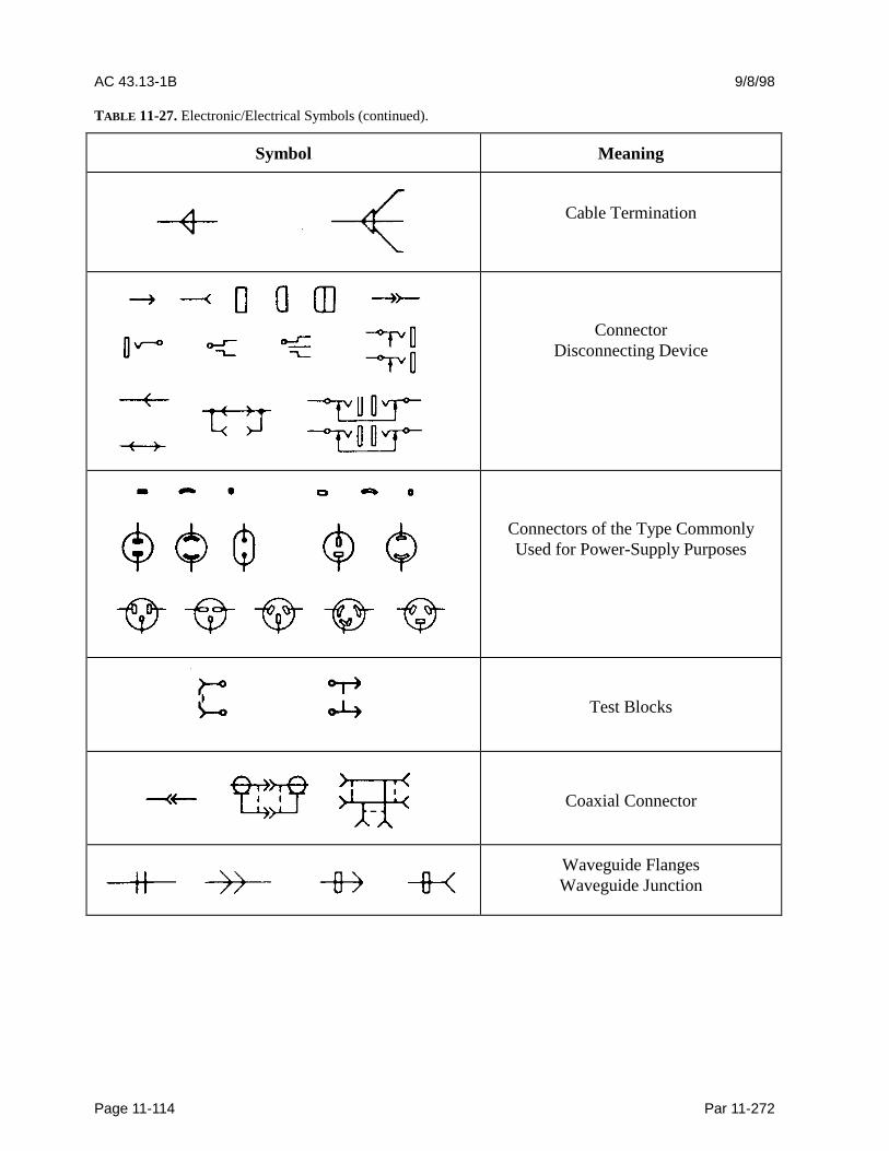
AC 43.13-1B 9/8/98
Page 11-114 Par 11-272
TABLE 11-27. Electronic/Electrical Symbols (continued).
Symbol Meaning
Cable Termination
ConnectorDisconnecting Device
Connectors of the Type CommonlyUsed for Power-Supply Purposes
Test Blocks
Coaxial Connector
Waveguide FlangesWaveguide Junction

9/8/98 AC 43.13-1B
Par 11-272 Page 11-115
TABLE 11-27. Electronic/Electrical Symbols (continued).
Symbol Meaning
Fuse
Lightning ArresterArrester
Gap
Circuit Breaker
Protective Relay
Audible-Signaling Device
Microphone

AC 43.13-1B 9/8/98
Page 11-116 Par 11-272
TABLE 11-27. Electronic/Electrical Symbols (continued).
Symbol Meaning
HandsetOperator’s Set
Lamp
Visual-Signaling Device
Mechanical ConnectionMechanical Interlock
Mechanical Motion
Clutch Brake
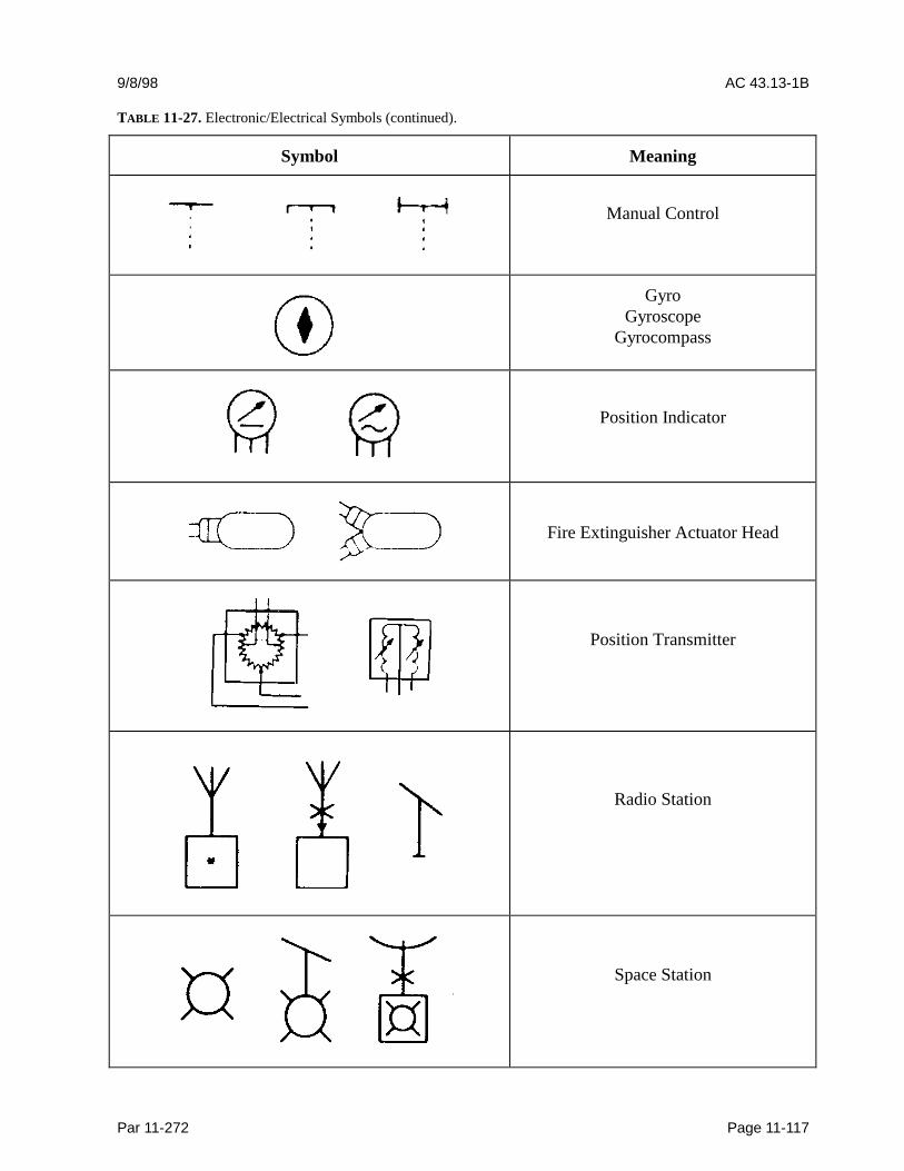
9/8/98 AC 43.13-1B
Par 11-272 Page 11-117
TABLE 11-27. Electronic/Electrical Symbols (continued).
Symbol Meaning
Manual Control
GyroGyroscope
Gyrocompass
Position Indicator
Fire Extinguisher Actuator Head
Position Transmitter
Radio Station
Space Station
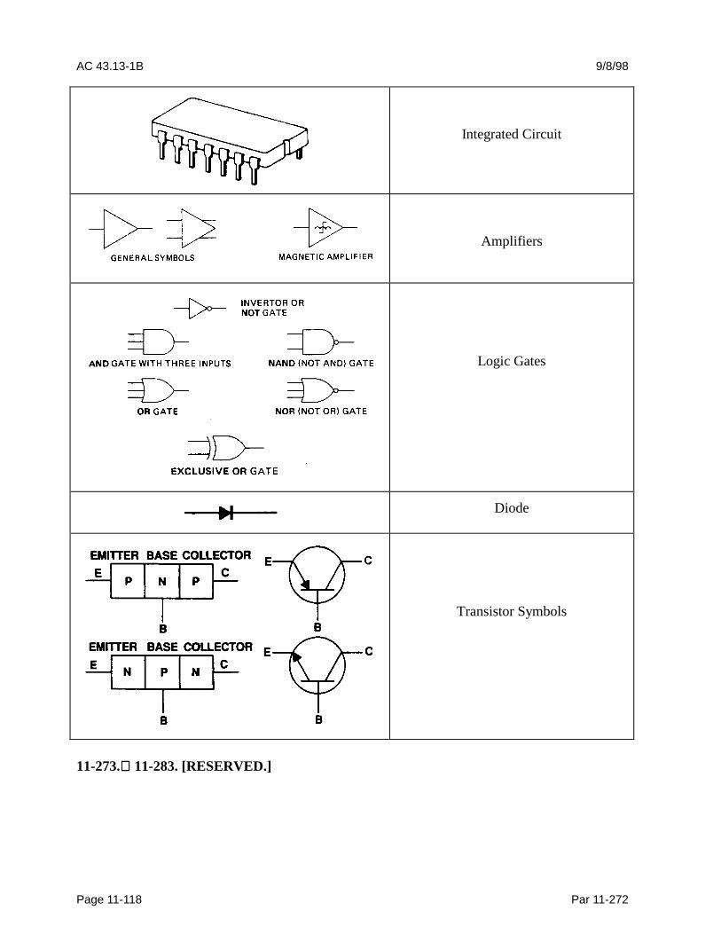
AC 43.13-1B 9/8/98
Page 11-118 Par 11-272
Integrated Circuit
Amplifiers
Logic Gates
Diode
Transistor Symbols
11-273. 11-283. [RESERVED.]


