Embed Size (px)
Citation preview
Chapter 11. Voice Synthesizer Project
Embedded Computing with PIC 16F877 – Assembly Language Approach. Charles Kim © 2006
311
Chapter 11. A Voice-Synthesizer Project
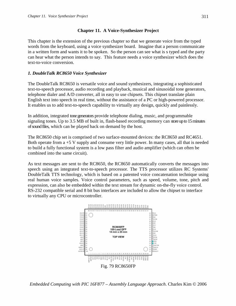
This chapter is the extension of the previous chapter so that we generate voice from the typed words from the keyboard, using a voice synthesizer board. Imagine that a person communicate in a written form and wants it to be spoken. So the person can see what is s typed and the party can hear what the person intends to say. This feature needs a voice synthesizer which does the text-to-voice conversion. 1. DoubleTalk RC8650 Voice Synthesizer The DoubleTalk RC8650 is versatile voice and sound synthesizers, integrating a sophisticated text-to-speech processor, audio recording and playback, musical and sinusoidal tone generators, telephone dialer and A/D converter, all in easy to use chipsets. This chipset translate plain English text into speech in real time, without the assistance of a PC or high-powered processor. It enables us to add text-to-speech capability to virtually any design, quickly and painlessly. In addition, integrated tone generators provide telephone dialing, music, and programmable signaling tones. Up to 3.5 MB of built in, flash-based recording memory can store up to 15 minutes of sound files, which can be played back on demand by the host. The RC8650 chip set is comprised of two surface-mounted devices: the RC8650 and RC4651. Both operate from a +5 V supply and consume very little power. In many cases, all that is needed to build a fully functional system is a low pass filter and audio amplifier (which can often be combined into the same circuit). As text messages are sent to the RC8650, the RC8650 automatically converts the messages into speech using an integrated text-to-speech processor. The TTS processor utilizes RC Systems' DoubleTalk TTS technology, which is based on a patented voice concatenation technique using real human voice samples. Voice control parameters, such as speed, volume, tone, pitch and expression, can also be embedded within the text stream for dynamic on-the-fly voice control. RS-232 compatible serial and 8 bit bus interfaces are included to allow the chipset to interface to virtually any CPU or microcontroller.
Fig. 79 RC8650FP

Chapter 11. Voice Synthesizer Project
Embedded Computing with PIC 16F877 – Assembly Language Approach. Charles Kim © 2006
312
Fig. 80 RC4651FP
The DoubleTalk RC8650 Evaluation Kit enables you to experiment with the RC Systems RC8650 voice synthesizer chip set. Included in the kit are:
• Evaluation board containing the RC8650 chip set • Speaker with volume control • Serial cable • RC8650 Studio software
The evaluation board is a complete, versatile voice synthesizer which can be used with the RC8650 Studio software as well as in stand-alone applications. The board includes the RC8650 voice synthesizer chip set, audio power amplifier, voltage regulator, RS-232C interface, and parallel I/O port. The chip set's I/O lines are made accessible through header connectors near the edge of the board. SW1 in the evaluation board is the Reset switch. Press once when we meet some problem.
Fig. 81 RC8650 Evaluation board
The RC8650 Studio software is NOT required, however, in order to use the evaluation board. The board can be used "stand-alone" if desired by simply printing the desired text and commands to it via the board's serial or parallel ports.

Chapter 11. Voice Synthesizer Project
Embedded Computing with PIC 16F877 – Assembly Language Approach. Charles Kim © 2006
313
So we directly tap the RXD and TXD pin of RC8650 chip set for direct serial communication with 16F877 without passing through RS-232 level converter such as MAX232. In this stand-alone application, a text word typed is voiced after a CR key is provided to RC8650 voice synthesizer. 2. Operating Modes of RC8650 Chip Set The RC8650 has six primary operating modes and two low-power modes designed to achieve maximum functionality and flexibility. The operating mode can be changed anytime, even on the fly. Note The RC8650 does not make any distinction between uppercase and lowercase characters. Text and commands may be sent as all uppercase, all lowercase, or any combination thereof. Text mode. In this mode, all text sent to the RC8650 is spoken as complete sentences. Punctuation is also taken into consideration by the intonation generation algorithms. The RC8650 will not begin speaking until it receives a CR (ASCII 13) or Null (ASCII 00) character—this ensures that sentence boundaries receive the proper inflection. This is the default operating mode. Character mode. This mode causes the RC8650 to translate input text on a character-by-character basis; i.e., text will be spelled instead of spoken as words. The RC8650 does not wait for a CR/Null in this mode. Phoneme mode. This mode disables the RC8650’s text-to-phonetics translator, allowing the RC8650’s phonemes to be directly accessed. Phonemes in the input buffer will not be spoken until a CR or Null is received. Real Time Audio Playback mode. In this mode, data sent to the RC8650 is written directly to its audio buffer. This results in a high data rate, but provides the capability of producing the highest quality speech, as well as sound effects. PCM and ADPCM data types are supported. Prerecorded Audio Playback mode. This mode allows recorded speech and sound effects to be stored on-chip and played back at a later time. PCM and ADPCM data types are supported. Tone Generator modes. These modes activate the RC8650’s musical tone generator, sinusoidal generator, or DTMF generator. They can be used to generate audible prompts, music, signaling tones, dial a telephone, etc. Idle mode. To help conserve power in battery-powered systems, the RC8650 automatically enters a reduced-power state whenever it is inactive. Data can still be read and written to the RC8650 while in this mode. Current draw in this mode is typically 1 mA. Standby mode. This mode powers down the RC8650, where current draw is typically only 2 µA. Standby mode can be invoked from either the STBY# pin or with the Sleep command. Data can-not be read from or written to the RC8650 in this mode.
Chapter 11. Voice Synthesizer Project
Embedded Computing with PIC 16F877 – Assembly Language Approach. Charles Kim © 2006
314
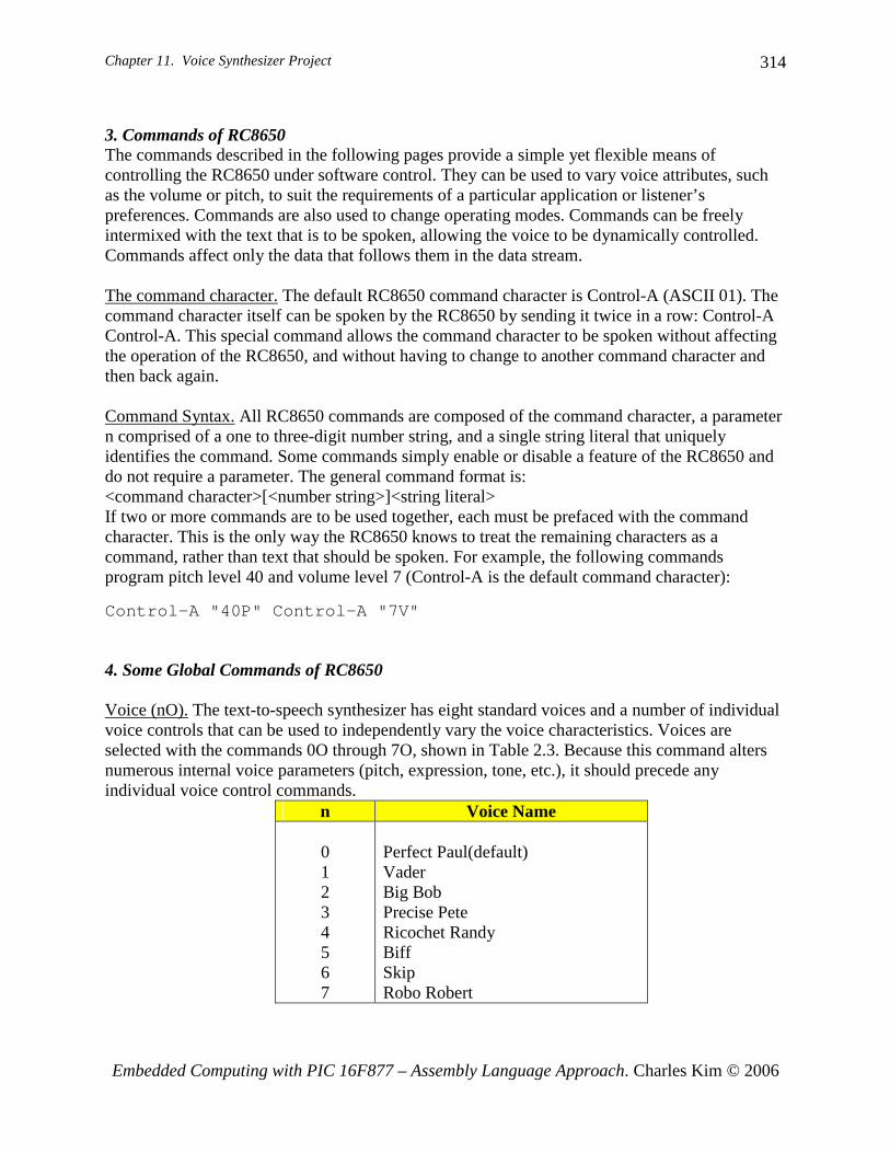
3. Commands of RC8650 The commands described in the following pages provide a simple yet flexible means of controlling the RC8650 under software control. They can be used to vary voice attributes, such as the volume or pitch, to suit the requirements of a particular application or listener’s preferences. Commands are also used to change operating modes. Commands can be freely intermixed with the text that is to be spoken, allowing the voice to be dynamically controlled. Commands affect only the data that follows them in the data stream. The command character. The default RC8650 command character is Control-A (ASCII 01). The command character itself can be spoken by the RC8650 by sending it twice in a row: Control-A Control-A. This special command allows the command character to be spoken without affecting the operation of the RC8650, and without having to change to another command character and then back again. Command Syntax. All RC8650 commands are composed of the command character, a parameter n comprised of a one to three-digit number string, and a single string literal that uniquely identifies the command. Some commands simply enable or disable a feature of the RC8650 and do not require a parameter. The general command format is: <command character>[<number string>]<string literal> If two or more commands are to be used together, each must be prefaced with the command character. This is the only way the RC8650 knows to treat the remaining characters as a command, rather than text that should be spoken. For example, the following commands program pitch level 40 and volume level 7 (Control-A is the default command character): Control-A "40P" Control-A "7V" 4. Some Global Commands of RC8650 Voice (nO). The text-to-speech synthesizer has eight standard voices and a number of individual voice controls that can be used to independently vary the voice characteristics. Voices are selected with the commands 0O through 7O, shown in Table 2.3. Because this command alters numerous internal voice parameters (pitch, expression, tone, etc.), it should precede any individual voice control commands.
n Voice Name 0 1 2 3 4 5 6 7
Perfect Paul(default) Vader Big Bob Precise Pete Ricochet Randy Biff Skip Robo Robert

Chapter 11. Voice Synthesizer Project
Embedded Computing with PIC 16F877 – Assembly Language Approach. Charles Kim © 2006
315
Volume (nV). This is a global command which controls the RC8650’s output volume level, from 0V through 9V. 0V yields the lowest possible volume; maximum volume is attained at 9V. The default volume is 5V. The Volume command can be used to set a new listening level, create emphasis in speech, or change the output level of the tone generators. DTMF Generator (n*). The DTMF (Touch-Tone) generator generates the 16 standard tone pairs commonly used in telephone systems. Each tone pair generated by the RC8650 is 100 ms in duration, more than satisfying the telephone signaling requirements (this can be extended to 500 ms with the Protocol Options Register command). The mapping of the command parameter n to the buttons on a telephone is shown below. The “pause” tone is used to generate the inter-digit delay in phone number strings. The generator’s output level can be adjusted with the Volume command ( nV). DTMF commands are buffered, and may be intermixed with text and other commands without restriction.
n Button 0 - - 9 10 11 12 13 14 15 16
0 - - 9 * # A B C D
pause 5. Coding Example for RC8650 As mentioned above we tap the RXD (pin#35) and TXD (pin# 36) of RC8650 chip for serial communication with 16F877. Since we need the hardware implemented serial communication and the MAX232 for hex code download from the PC we work for coding, we utilize the software implemented serial communication (refer to Chapter 6) for the connection with RC8650, and we pick RD5 and RD4 for RX and TX pins for 16F877, respectively.

Chapter 11. Voice Synthesizer Project
Embedded Computing with PIC 16F877 – Assembly Language Approach. Charles Kim © 2006
316
Fig. 82 RC8650 connection to PIC 16F877
The example code is to simply dial a number and generate the voice for a text of "I LOVE YOU." We will test all 8 different voices supported by the chip set and control volume of the voice. First we can set the volume to 4 by the following routine. Since every command should start with the command character Control-A, we start with it and use the global command format for volume. Note that every command and attribute is entered as character. CTRLA is declared as 0x01 ASCII code. Subroutine TXSW is 19200 bps software generated serial communication (transmission) routine that we already discussed in Chapter 6. ;
movlw CTRLAcall TXSWmovlw '4'call TXSWmovlw 'V'call TXSW ;Send CTRL-A > 4 > V
For voice, we want to apply all 8 different voices, so we first assign 0 to a register, VOICE, and increase by 1 after we generate the sound of the text "I Love You". By the way, the default operational mode of RC8650 chip set is the text-mode which coverts text to voice. The phone dialing precedes the "I Love You" message. The phone dialing, or DTMF generation, is done by the following order of command and each digit of phone number:

Chapter 11. Voice Synthesizer Project
Embedded Computing with PIC 16F877 – Assembly Language Approach. Charles Kim © 2006
317
CTRL-A > Digit_1>*>CTRL-A>Digit_2>* ......CTRL-A>Digit_n>*. In other words, the CTRL-A should come before the number and it should be followed by the star (*) mark. The following instructions dial and generate DTMF of the author's office number:202-806-4821 with preceding '1' for long distance call indication.
movlw CTRLAcall TXSWmovlw '1'call TXSWmovlw '*'call TXSW
movlw CTRLAcall TXSWmovlw '2'call TXSWmovlw '*'call TXSW
movlw CTRLAcall TXSWmovlw '0'call TXSWmovlw '*'call TXSW
movlw CTRLAcall TXSWmovlw '2'call TXSWmovlw TXSW
movlw CTRLAcall TXSWmovlw '8'call TXSWmovlw '*'call TXSW
movlw CTRLAcall TXSWmovlw '0'call TXSWmovlw '*'call TXSW
movlw CTRLA

Chapter 11. Voice Synthesizer Project
Embedded Computing with PIC 16F877 – Assembly Language Approach. Charles Kim © 2006
318
call TXSWmovlw '6'call TXSWmovlw '*'call TXSW
movlw CTRLAcall TXSWmovlw '4'call TXSWmovlw '*'call TXSW
movlw CTRLAcall TXSWmovlw '8'call TXSWmovlw '*'call TXSW
movlw CTRLAcall TXSWmovlw '2'call TXSWmovlw '*'call TXSW
movlw CTRLAcall TXSWmovlw '1'call TXSWmovlw '*'call TXSW
This long lines of the code can be simplified by developing a subroutine and a table. First, let's make a table for the phone number: ;=== Phone Number Table=PhoneTable
movf PHONEdigit,0addwf PCL
;PC+0DT "12028064821" ;11 numbersretlw 0
As we see above it looks very clean and simple with table format. Now let's have a dialing subroutine which dials the numbers stored in the PhoneTable table. In the Dialing subroutine, the PhoneTable is called 11 times, and at each time, with PC increased, the next number is restored to W register for writing to RC8650. The command CTRL-A and star mark (*) are wrapping the phone number for DTMF generation.

Chapter 11. Voice Synthesizer Project
Embedded Computing with PIC 16F877 – Assembly Language Approach. Charles Kim © 2006
319
Dialing movlw 0x0B ;11 phone digits
movwf Ptempclrf PHONEdigit
Dagain movlw CTRLAcall TXSWcall PhoneTable ;get the numbercall TXSWmovlw '*'call TXSWincf PHONEdigitdecfsz Ptempgoto Dagainreturn
The burst duration of the DTMF is 100ms in the default setting of the chip set. We can change the duration to 500ms by changing the content of Protocol Options Register of the chip set. Details on this subject is left to the readers, and here goes the command for 500ms burst duration: CTRL-A >"1">"6">"0">"G". Selection of a voice comes with CTRL-A followed by the voice number, 0 through 7, and the letter O, as shown below
movlw CTRLAcall TXSWmovf VOICE,0 ;write the VOICEcall TXSWmovlw 'O'call TXSW
Since the text mode is the default mode of RC8650, write a message is pretty simple. For "I Love You! " message, we go like this:
movlw 'I'call TXSWmovlw ' ' ;spacecall TXSWmovlw 'L'call TXSWmovlw 'o'call TXSWmovlw 'v'call TXSWmovlw 'e'call TXSWmovlw ' ' ;spacecall TXSWmovlw 'Y'call TXSWmovlw 'o'call TXSWmovlw 'u'

Chapter 11. Voice Synthesizer Project
Embedded Computing with PIC 16F877 – Assembly Language Approach. Charles Kim © 2006
320
call TXSWmovlw 'I'call TXSW
As we did in phone number, the text message can also be simplified by a subroutine and a table. First, the message table looks like this: MessageTable
movf MESSAGEdigit,0addwf PCLDT "I LOVE YOU!" ;11 textsretlw 0
And the subroutine for text message writing goes as shown below. There are 11 character readings and writings without any other commands and command characters. When all characters in the text message are read, then CR is written to RC8650 to signal the end of the text message and to request for conversion to voice. ;Subroutine MessageMessage
movlw 0x0B ;11 charactersmovwf Mtempclrf MESSAGEdigit
Magaincall MessageTable ;read a textcall TXSWincf MESSAGEdigitdecfsz Mtempgoto Magainmovlw 0x0Dcall TXSW ;CR key for voicing after 11 readingsreturn
Since this is the first incidence of RC8650 voice synthesizer application, the following code lists the full program. When you run this, you would hear very quick digital dialing sound from the speaker (100ms per each digit) followed by a voice saying "I Love You." This dialing and message repeats for 8 different voices. ;RC8650.asm;;TABLE IS USED TO SIMPLIFY THE PROGRAM; FOR PHONE NUMBER;AND;TEXT MESSAGE;;This program is to:; 1. test the RCS8650 voice synthesizer evaluation board; 2. Send ASCII word followed by CR key; 3. Then the sound must be generated from the speaker attached to the board; 4. Connection; DB9 of 16F877 to DB9 of RC6850 Board;; This connection is made without using MAX232 chips at both sides
Chapter 11. Voice Synthesizer Project
Embedded Computing with PIC 16F877 – Assembly Language Approach. Charles Kim © 2006
321
;Direct connection between 16F877 and RC8650
; Baud rate for this is set as 19200;;This program is asynchronous communication using software method;;F = 20 MHz;B = Baud Rate;For B=19200, one Baud cycle (BC) is about 52uS;;;TRANSMIT MODE;First START bit is sent by setting the TX pin to LOW for (BC) seconds;And, from then on, the TX Pin is Set/Cleared corresponding to the data bit;every (BC) seconds.;8N1 format;;TX Pin = RD4;RX Pin = RD5;;Terminal set up: 8N1 19200;;
list P = 16F877
PCL EQU 0x02STATUS EQU 0x03CARRY EQU 0x00TRISD EQU 0x88PORTD EQU 0x08TXPIN EQU 0x04 ;RD4RXPIN EQU 0x05 ;RD5MSB EQU 0x07CTRLA EQU 0x01 ;RC8650 Command Character;;note
;RAM for DELAY SUBROUTINECBLOCK 0x20 ; RAM AREA for USE at address 20h
PHONEdigitPtempMESSAGEdigitMtempVOICEKount52usKount100usKount10msKount100msKount1sRCSreg ;data to RCS's RC8650Bitcount ;data bit countKount ;Delay count (number of instr cycles for delay)
ENDC
;=========================================================

Chapter 11. Voice Synthesizer Project
Embedded Computing with PIC 16F877 – Assembly Language Approach. Charles Kim © 2006
322
org 0x0000 ;line 1GOTO START ;line 2 ($0000)
;======================================================org 0x05
START
banksel TRISD; Port setting (1 for input and 0 for output); 1110 0000
movlw 0xE0movwf TRISDbanksel PORTDbcf PORTD,0x00bcf PORTD,0x01
;RD4 - TXPin (out) RD5 - RXPin (in)
;TEXT MODE is DEFAULT MODE
;Default mode of RC8650 is Text mode;So keep this;Change the volume by nV command;n = [0,9] with 5 as default;Change to 4
movlw CTRLAcall TXSWmovlw '4'call TXSWmovlw 'V'call TXSW
movlw 0x30movwf VOICE ;starting from 0
BEGINbanksel RCSregclrf RCSreg
;Change the Voice to nO command;0 for Perfect Paul (Default);1 for Vader;2 for Big Bob;3 for Precise Pete;4 for Ricochet Randy;5 for Biff;6 for Skip;7 for Robo Robert;;Apply all 8 voices one at a time
movlw CTRLAcall TXSWmovf VOICE,0 ;write the VOICEcall TXSWmovlw 'O'

Chapter 11. Voice Synthesizer Project
Embedded Computing with PIC 16F877 – Assembly Language Approach. Charles Kim © 2006
323
call TXSW;
call Dialingcall delay1scall delay1s
;Text Message
call Messagecall delay1scall delay1s
;next voiceincf VOICEbtfss VOICE,0x03 ;third bit =1 means VOICE=8goto BEGINmovlw 0x30movwf VOICE ;again with 0call delay1scall delay1sgoto BEGIN
;=== Phone Number Table=PhoneTable
movf PHONEdigit,0addwf PCL
;PC+0DT "12028064821" ;11 numbersretlw 0
;MessageTable
movf MESSAGEdigit,0addwf PCLDT "I LOVE YOU!" ;11 textsretlw 0
;;Subroutine Dialing
;DTMF Generation (command is n*);Call the following Number;1-202-806-4821;DTMPF usual (default) burst duration is 100ms;this could become 500ms by changing the Protocol Options Register;by nG command; CTRLA>"1">"6">"0">"G" would change it to 500ms;Fro details see the RC8650 data sheetDialing
movlw 0x0B ;11 phone digitsmovwf Ptempclrf PHONEdigit
Dagainmovlw CTRLAcall TXSWcall PhoneTable

Chapter 11. Voice Synthesizer Project
Embedded Computing with PIC 16F877 – Assembly Language Approach. Charles Kim © 2006
324
call TXSWmovlw '*'call TXSWincf PHONEdigitdecfsz Ptempgoto Dagainreturn
;;Subroutine MessageMessage
movlw 0x0B ;11 charactersmovwf Mtempclrf MESSAGEdigit
Magaincall MessageTablecall TXSWincf MESSAGEdigitdecfsz Mtempgoto Magainmovlw 0x0Dcall TXSW ;CR key for voicingreturn
;Software TX routine;The data to be sent is stored in WTXSW
banksel RCSregmovwf RCSregmovlw 0x08 ;8 --->Wmovwf Bitcount ;8 data bits
;send a START bitbcf PORTD, TXPin
;delay for 1*(BC) cyclescall Delay52us ;Keep this!
TXNEXTbcf STATUS, CARRYrrf RCSreg ;LSB first mode (normal)btfsc STATUS,CARRYbsf PORTD, TXPinbtfss STATUS,CARRYbcf PORTD, TXPincall Delay52usdecfsz Bitcountgoto TXNEXT
;send STOP bitbsf PORTD, TXPincall Delay52us ;
;wait until the end of STOP bitreturn
;;===SUBROUTINES ====;delay 52us for one baud cycle of 19200 bpsDelay52us
movlw 0x54
Chapter 11. Voice Synthesizer Project
Embedded Computing with PIC 16F877 – Assembly Language Approach. Charles Kim © 2006
325
movwf Kount52usR52us decfsz Kount52us
goto R52usreturn
;==========================================================;DELAY SUBROUTINES;;100us delay needs 500 instruction cycles; 500 =166*3 +2 ---->Kount=166=0xA6; or =165*3 +5 ---->Kount=165=0xA5; or =164*3 +8 ---->Kount=164=0xA4Delay100us
banksel Kount100usmovlw H'A4'movwf Kount100us
R100usdecfsz Kount100usgoto R100usreturn
;;10ms delay; call 100 times of 100 us delay (with some time discrepancy)Delay10ms
banksel Kount10msmovlw H'64' ;100movwf Kount10ms
R10ms call delay100usdecfsz Kount10msgoto R10msreturn
;;1 sec delay;call 100 times of 10ms delayDelay1s
banksel Kount1smovlw H'64'movwf Kount1s
R1s call Delay10msdecfsz Kount1sgoto R1sreturn
;;END OF CODE
END
3. Coding for a Complete System of Voice Synthesizer, LCD, and Keyboard Now, it's about time to connect the keyboard, the LCD module, and the RC8650 evaluation system for the final version of this application. Our scheme here is that the keyed characters are displayed to the LCD module and that the texts are pronounced as text message when CR key is entered. As we know, the CR key also moves the cursor to the first position of the next line of

Chapter 11. Voice Synthesizer Project
Embedded Computing with PIC 16F877 – Assembly Language Approach. Charles Kim © 2006
326
the current cursor position. The schematic for the connections and pin assignments are as shown below.
Fig. 83 Keyboard and LCD module connection to RC8650 evaluation system Before we examine an example code for this final version, let's consider some new stuffs we bring to the project compared with the previous version. First, we have to have a storage space to store texts so that, when CR is pressed, we retrieve them and write to the RC8650 chip set for text-to-voice conversion. Second, we have to accommodate the BS key. When BS key is pressed, we have to not only move the cursor on LCD module to move back by one space but also change the stored text so that the keys after the BS overrides the text previously entered in to a storage location. Let's discuss about saving the entered characters. Since we have general purpose register spaces in Bank 1 (Bank 0 spaces are usually occupied by the variables defined in the program.) of the RAM, we will going to use the first 80 bytes of the free space in Bank 1. Since we have 4x20 (total of 80 characters), the first 80 spaces, starting from address A0h, completely fit to our purpose. For this allocation, we will use an indirect addressing mode by using INDF and FSR registers. INDF register is the indirect file register to hold a byte data and FSR is the file register selection register. The content of FSR is the address of INDF. INDF is not a physical register and FSR is the address pointer for INDF. In other words, if FSR contains A0h, and if you have the following instruction:
movlw 'A'movwf INDF
Then, the hex number 41h (for 'A') would be written to the address A0h indicated by FSR. If you want to write 'B' at the address A1h, you increase FSR by 1 and write it to INDF:

Chapter 11. Voice Synthesizer Project
Embedded Computing with PIC 16F877 – Assembly Language Approach. Charles Kim © 2006
327
incf FSRmovlw 'B'movwf INDF
So, as we wee here, there is no direct contact or control with INDF register, instead, they are performed via FSR. In example code, we store any character to the storage space staring at A0h until we receive a CR key. When CR is entered, we send the whole text to RC8650 chip set followed by CR (which triggers the text to voice conversion). After the conversion, we move the FSR to the original A0h address so that the next can be overwritten. So, whenever a text (other than CR or BS) is entered, it is interpreted to ASCII character using the table of NoSHiftKeyTable, ShiftKeyTable, or CAPKeyTable, depending upon the pressing of Shift or Caps Lock key, or not. Then, it is displayed on the LCD module, and at the same time, the storage address for the text is increased by 1 and the count for number of texts entered is also increased by 1. The variable Nchar in the instruction below monitors the number of texts stored for the voice conversion. An example code when no Shift or Caps Lock key is pressed.
call NoShiftKeyTable ;(X) displaymovwf INDF ;store the character at INDFincf FSRincf Ncharcall LCDisplay
An example code when Caps Lock key is pressed.
call CAPKeyTablemovwf INDF ;store the character at INDFincf FSRincf Ncharcall LCDisplay
The subroutine for converting the stored texts into voice is shown below. The subroutine VoiceText changes the RC8650 mode to text mode (this is not required since the default mode is the text mode), then write the stored texts as numbered by the content of Nchar in the software implemented, asynchronous serial communication routine TXSW. After writing all the texts stored, it then sends CR to trigger the RC8650 to convert the texts to voice. Once the job is done, it moves the storage starting address to A0h. ;subroutineVoiceText;if Nchar=0 return (nothing to display)
movlw CTRLAcall TXSWmovlw 'T'call TXSW ;text mode

Chapter 11. Voice Synthesizer Project
Embedded Computing with PIC 16F877 – Assembly Language Approach. Charles Kim © 2006
328
banksel Ncharmovf Nchar,0clrf STATUSxorlw 0x00btfsc STATUS,ZEROreturnmovlw 0xA0movwf FSR
NextCharmovf INDF,0call TXSWdecfsz Nchargoto domoremovlw 0x0D ;voice ONcall TXSWmovlw 0xA0movwf FSRreturn
DOmoreincf FSRgoto NextChar
When BS key in entered, the address pointer for the text must be decreased by 1 and the number of texts must be also decreased by 1:
decf FSRdecf Nchar
Even though we discussed in detail about the LCD display of the keyboard keys, since this final version involves very important part of voice conversion, the following code lists the full program for the connection of a AT or PS/2 type keyboard, an 20x4 LCD module with 4-bit interfacing scheme, and a voice synthesize chip set of RC8650. Check for the changes in the PCLATH related instruction at the tables. ;kbd6.asm;;kbd-LCD-Voice Synthesizer connection;CR key will start the text-voice conversion;;texts tpyed are stored at the RAM space (bank 1) starting @A0;using FSR pointer and INDF register;FSR directs the INDF register;When CR is entered, then the text-voice routine is called;to make sounds.;; Baud rate for this is set as 19200 for SW enabled Serial Communication; to RC8650 Chip Set;;This program is asynchronous communication using software method

Chapter 11. Voice Synthesizer Project
Embedded Computing with PIC 16F877 – Assembly Language Approach. Charles Kim © 2006
329
;;F = 20 MHz;B = Baud Rate;For B=19200, one Baud cycle (BC) is about 52uS;;;TRANSMIT MODE;First START bit is sent by setting the TX pin to LOW for (BC) seconds;And, from then on, the TX Pin is Set/Cleared corresponding to the data bit;every (BC) seconds.;8N1 format;;TX Pin = RD4;RX Pin = RD5;; LCD is with 4-bit interfacing;;CR key would change the line;; Pin Connection from LCD to 16F877; LCD (pin#) 16F877 (pin#);DB7 (14) -----RB7(40);DB6 (13) ----RB6(39);DB5 (12) ----RB5(38);DB4 (11) ----RB4(37);E (6) ------RB2(35);RW (5) -----RB3(36);RS (4) -----RB1(24);Vo (3) -----GND;Vdd (2) ----+5V;Vss (1) -----GND;;KEYBOARD Interfacing;CLOCK -----RD7 (input);DATA ------RD6 (input);;==RC8650 pin connection ==;RD4 - TXPin (out);RD5 - RXPin (in)
list P = 16F877INDF EQU 0x00 ;indirect registerFSR EQU 0x04 ;Pinter of INDFSTATUS EQU 0x03PCL EQU 0x02 ;For Key Table CallingPCLATH EQU 0x0A ;upper part of PCCARRY EQU 0x00BORROW EQU 0x00ZERO EQU 0x02PORTB EQU 0x06TRISB EQU 0x86RS EQU 0x01 ;RB1E EQU 0x02 ;RB2RW EQU 0x03 ;RB3TRISD EQU 0x88PORTD EQU 0x08CARRY EQU 0x00

Chapter 11. Voice Synthesizer Project
Embedded Computing with PIC 16F877 – Assembly Language Approach. Charles Kim © 2006
330
MSB EQU 0x07CLOCK EQU 0x07 ;from Keyboard (RD7)KDATA EQU 0x06 ;from Keyboard (RD6)TXPIN EQU 0x04 ;to RC8650RXPIN EQU 0x05 ;RD5MSB EQU 0x07CTRLA EQU 0x01 ;RC8650 Command Character
;RAM Area
CBLOCK 0x20RCSreg ;RC8650VOICE
;CURSOR ;tracking the current display position
;CURSOR (tracking purpose) (Decimal);1 2 3 4 5 6 7 8 9 10 11 12 13 14 15 16 17 18 19 20 line1;21 22 23 24 25 26 27 28 29 30 31 32 33 34 35 36 37 38 39 40 line 2;41 42 43 44 45 46 47 48 49 50 51 52 53 54 55 56 57 58 59 60 line 3;61 62 63 64 65 66 67 68 69 70 71 72 73 74 75 76 77 78 79 80 line 4;;DDADDR CONTENT read from LCD Module (HEX);00 01 02 03 04 05 06 07 08 09 0A 0B 0C 0D 0E 0F 10 11 12 13 line1;40 41 42 43 44 45 46 47 48 49 4A 4B 4C 4D 4E 4F 50 51 52 53 line 2;14 15 16 17 18 19 1A 1B 1C 1D 1E 1F 20 21 22 23 24 25 26 27 line 3;54 55 56 57 58 59 5A 5B 5C 5D 5E 5F 60 61 62 63 64 65 66 67 line 3
DDaddr ;Display address (cursor pos)DDtemp1DDtemp2Nchar
Dkey ;Key character to be displayedDATAregBitcountKstatKount52usKount120us ;Delay count (number of instr cycles for delay)Kount100usKount1msKount10msKount100msKount1sKount10sKount1mTemp ;temp storage
ENDC
;program should start from 0005h;0004h is allocated to interrupt handler
org 0x0000goto START
org 0x05
Chapter 11. Voice Synthesizer Project
Embedded Computing with PIC 16F877 – Assembly Language Approach. Charles Kim © 2006
331
Start
banksel TRISD; 1100 0000
movlw B'11100000' ;Rd7 for CLOCK and Rd6 for DATA as inputs;rd5 as RX from RC8600;rd4 as TX to RC8600
movwf TRISD
call delay1s ;Give Keyboard to send STATUS to the host
BANKSEL TRISBmovlw 0x00movwf TRISB ;All output
banksel PORTBclrf PORTB ;RW set LOW here
clrf CURSOR ;Current Display Locationincf CURSOR ;Home cursor position (1, 1)
;LCD routine startscall delay10mscall delay10ms
banksel PORTBclrf PORTB ;RW set LOW here
;give LCD module to reset automaticallycall LCD4INIT
;END OF LCD INITIALIZATION;RC8600 setup;TEXT MODE is DEFAULT MODE
;Default mode of RC8650 is Text mode;So keep this;Change the volume by nV command;n = [0,9] with 5 as default;Change to 6
movlw CTRLAcall TXSWmovlw '6'call TXSWmovlw 'V'call TXSW
;VOICE TYpE SELECTION;Change the Voice to nO command;0 for Perfect Paul (Default);1 for Vader;2 for Big Bob;3 for Precise Pete;4 for Ricochet Randy;5 for Biff;6 for Skip;7 for Robo Robert
movlw CTRLA

Chapter 11. Voice Synthesizer Project
Embedded Computing with PIC 16F877 – Assembly Language Approach. Charles Kim © 2006
332
call TXSWmovwf '1' ;perfect Paulcall TXSWmovlw 'O'call TXSW
;movlw 0xA0movwf FSR ;data pointer @A0 in Bank 1
;receiving databanksel Ncharclrf NCHAR ;number of data entered
;=============================================================;KBD MonitoringBEGIN
banksel DATAregclrf DATAregclrf DDADDR ;DD RAM ADDRESS READ from LCD
;; CHECK IF THE CLOCK is HIGH at least for 10mS
banksel PORTDbtfss PORTD, CLOCKgoto BEGIN ;if CLOCK is LOW, start againcall Delay10ms ;10mS delays
;check again for CLCOKbtfss PORTD, CLOCKgoto BEGIN
;READY FOR CLOCK PULSES
clrf KSTATKEYIN;X reading
call RX11bit ;clrf STATUSmovf DATAreg,0 ;Break Code?xorlw 0xF0btfss STATUS,ZEROgoto CAT
;BREAK is detected. Abort It. Resume Itgoto BEGIN
;Category detectionCAT clrf STATUS
movf DATAreg,0xorlw 0xE0btfsc STATUS,ZEROgoto Begin ;E0 keys (CAT2) are ignoredclrf STATUSmovf DATAreg,0xorlw 0x12btfsc STATUS,ZEROgoto LRSHIFTclrf STATUSmovf DATAreg,0xorlw 0x59btfsc STATUS,ZERO

Chapter 11. Voice Synthesizer Project
Embedded Computing with PIC 16F877 – Assembly Language Approach. Charles Kim © 2006
333
goto LRSHIFTclrf STATUSmovf DATAreg,0xorlw 0x58 ;CAPS LOCKbtfsc STATUS,ZEROgoto CAPSmovf DATAreg,0clrf STATUS ;CR checkxorlw 0x5Abtfsc STATUS,ZEROgoto CRhandlemovf DATAreg,0clrf STATUSxorlw 0x66btfsc STATUS,ZEROgoto BShandle ;Back Space Handling
;L Shift ===>12 | F0 12;R Shift ===>59 | F0 59
;CAT1 has the format of (X)|(F0)(X)CAT1 movf DATAreg,0;check if the key in is CR;Then we have to move the next line
call NoShiftKeyTable ;(X) displaymovwf INDF ;store the character at INDFincf FSRincf Ncharcall LCDisplay
;(F0) detectioncall RX11bitclrf STATUSmovf DATAreg,0xorlw 0xF0btfss STATUS,ZERO
;Key is not broken. Still pressed,goto CAT1
;Key is broken;Last (X) reading
call RX11bit ;(X) after F0
goto BEGIN
;L-SHIT and R-SHIFT has the form;L-SHIFT and a character 12 X | F0 X |F0 12;R-SHIFT and a character 59 X | F0 X |F0 59
LRSHIFT ;12 or 59 entered
;(F0) detectioncall RX11bitclrf STATUSmovf DATAreg,0xorlw 0xF0btfsc STATUS,ZEROgoto BEGIN
;X

Chapter 11. Voice Synthesizer Project
Embedded Computing with PIC 16F877 – Assembly Language Approach. Charles Kim © 2006
334
clrf STATUS ;if (12) do not displaymovf DATAreg,0xorlw 0x12btfsc STATUS, ZEROgoto LRSHIFT
clrf STATUS ;if (59) do not displaymovf DATAreg,0xorlw 0x59btfsc STATUS, ZEROgoto LRSHIFT
;a Key (X) is enteredmovf DATAreg,0call ShiftKeyTablemovwf INDF ;store the character at INDFincf FSRincf Ncharcall LCDisplay
;(F0) detectioncall RX11bitclrf STATUSmovf DATAreg,0xorlw 0xF0btfss STATUS,ZEROgoto LRSHIFT
;Last (X) readingcall RX11bitmovf DATAreg,0clrf STATUS ;check if (X) or (12) entered after F0xorlw 0x12btfsc STATUS,ZEROgoto BEGINgoto LRSHIFT
;CAPS ;caps lock (58) entered
;(F0) detectioncall RX11bit ;this must be F0call RX11bit ;this must be (58) again
CAPnextcall RX11bit ;Check if (58) or otherclrf STATUSmovf DATAreg,0xorlw 0x58btfss STATUS,ZEROgoto CAPtwo ;End of CAP sessioncall RX11bit ;F0call RX11bit ;(58)goto BEGIN
;a Key (X) is enteredCAPtwo
movf DATAreg,0

Chapter 11. Voice Synthesizer Project
Embedded Computing with PIC 16F877 – Assembly Language Approach. Charles Kim © 2006
335
call CAPKeyTablemovwf INDF ;store the character at INDFincf FSRincf Ncharcall LCDisplay
;(F0) detectioncall RX11bit ;thisclrf STATUSmovf DATAreg,0xorlw 0xF0btfss STATUS,ZEROgoto CAPtwo
;Last (X) reading ;F0 is readcall RX11bit ;(X) again and ignoregoto CAPnext
;CR handlingCRhandle
call RX11bit ;F0 readcall RX11bit ;CR reading again
; text-voice conversioncall VoiceText
;;read the current cursor position
call readad4;DDADDR has the content;NOTE: MSB must be 1 in the cursor command
bsf DDADDR, MSB;if DDADDR<94, then new cursor position is C0;if DDADDR<E8, then 80;if DDADDR<C0, then D4;if DDADDR<D4, then 94
clrf STATUSmovf DDADDR,0sublw 0x94 ;k-W -->Wbtfsc STATUS,Borrow ;No borrow means that k>Wgoto CR94 ; is less than 94clrf STATUSmovf DDADDR,0sublw 0xC0btfsc STATUS,Borrowgoto CRC0
clrf STATUSmovf DDADDR,0sublw 0xD4btfsc STATUS,Borrowgoto CRD4
clrf STATUSmovf DDADDR,0sublw 0xE8btfsc STATUS,Borrow

Chapter 11. Voice Synthesizer Project
Embedded Computing with PIC 16F877 – Assembly Language Approach. Charles Kim © 2006
336
goto CRE8goto BEGIN
CR94 call posline12goto begin
CRC0 call posline14goto BEGIN
CRD4 call posline13goto BEGIN
CRE8 call LCDclearhome ;clear screen firstcall posline11goto BEGIN
;CRE8 call posline11; goto BEGIN
;BS HandlingBShandle
movf DATAreg,0 ;W holds $66call RX11bit ;F0 readcall RX11bit ;BS break code
;read the current cursor positioncall readad4
;DDADDR has the content; SO move the current to the left;NOTE: MSB must be 1 for commanding of the cursor position
bsf DDADDR, MSB;if DDADDR = 94, then new cursor position is D3;if DDADDR = C0, then new position is 93;if DDADDR = D4, then new position is A7;if DDADDR = 80, then new position is 80 (NO CHANGE); all other cases, new position is (DDADDR - 1)
clrf STATUSmovf DDADDR,0xorlw 0x94btfsc STATUS, ZEROgoto DD94clrf STATUSmovf DDADDR,0xorlw 0xC0btfsc STATUS,ZEROgoto DDC0clrf STATUSmovf DDADDR,0xorlw 0xD4btfsc STATUS,ZEROgoto DDD4clrf STATUSmovf DDADDR,0xorlw 0x80btfsc STATUS,ZEROgoto DD80
;all others

Chapter 11. Voice Synthesizer Project
Embedded Computing with PIC 16F877 – Assembly Language Approach. Charles Kim © 2006
337
decf DDADDRdecf CURSORmovf DDADDR,0call instw4decf FSRdecf Nchargoto BEGIN
DD94 movlw 0xD3decf CURSORcall instw4decf FSRdecf Nchargoto BEGIN
DDC0 movlw 0x93decf CURSORcall instw4decf FSRdecf Nchargoto BEGIN
DDD4 movlw 0xA7decf CURSORcall instw4decf FSRdecf Nchargoto BEGIN
DD80 movlw 0x80call instw4decf FSRdecf Nchargoto BEGIN
;
;======================================================;SUBROUTINE LCD4INIT;Function for 4-bit (only one write must be done);In other words, send only the high nibbleLCD4INIT;IMPORTANT PART
movlw 0x28call hnibble4
;Function for 4-bit, 2-line display, and 5x8 dot matrixmovlw 0x28call instw4
;Display On, CUrsor On, No blinkingmovlw 0x0E ;0F would blinkcall instw4
;DDRAM address increment by one & cursor shift to rightmovlw 0x06call instw4
;DISPLAY CLEARCLEAR

Chapter 11. Voice Synthesizer Project
Embedded Computing with PIC 16F877 – Assembly Language Approach. Charles Kim © 2006
338
movlw 0x01call instw4
;call posline11 ;pos1 and line 1
;now CURSOR=1return
;=================================================
;LCD DISPLAYING SUBROUTINELCDisplay
call dataw4incf CURSOR ;every time of display, increase cursor
;CURSOR is automatically incremented by 1 from LCDisplay;if CURSOR is 20 (0x14), change to posline12;if CURSOR is 40 (0x28), change to posline13;if CURSOR is 60 (0x3C), change to posline14;if CURSOR is 80 (0x50), change to posline11
clrf STATUSmovf CURSOR,0xorlw 0x15btfsc STATUS, ZEROgoto Toline2
clrf STATUSmovf CURSOR,0xorlw 0x29btfsc STATUS,ZEROgoto Toline3
clrf STATUSmovf CURSOR,0xorlw 0x3Dbtfsc STATUS,ZEROgoto Toline4
clrf STATUSmovf CURSOR,0xorlw 0x51btfsc STATUS,ZEROcall LCDClearhome ;delete all and move to (1,1)return
Toline2call posline12return
Toline3call posline13return
Toline4call posline14return
;SUBROUTINE;DISPLAY CLEAR and Cursor to Home position (line 1, position 1)LCDclearhome
movlw 0x01

Chapter 11. Voice Synthesizer Project
Embedded Computing with PIC 16F877 – Assembly Language Approach. Charles Kim © 2006
339
call instw4;Now let's move the cursor to the home position (position 1 of line #1);and set the DDRAM address to 0. This is done by the "return home"instruction.
movlw 0x02call instw4
;home positionmovlw 0x80call instw4movlw 0x01movwf CURSORreturn
;====SUBROUTINES =====posline11;Position to pos 1 and line 1
movlw 0x80call instw4movlw 0x01movwf CURSORreturn
posline12 ;pos 1 and line 2movlw 0xC0call instw4movlw 0x15 ;21movwf CURSORreturn
posline13 ;pos1 and line3movlw 0x94call instw4movlw 0x29 ;41movwf CURSORreturn
posline14 ;pos 1 and line 4movlw 0xD4call instw4movlw 0x3D ;61movwf CURSORreturn
;;high nibble only write for the first step of 4-bit set uphnibble4
movwf Temp ;Temp storagemovf Temp,0 ;Now W also holds the dataandlw 0xF0 ; get upper nibblemovwf PORTB ; send data to lcdcall delay1msbcf PORTB, RScall delay1msbsf PORTB, Ecall delay1msbcf PORTB, E

Chapter 11. Voice Synthesizer Project
Embedded Computing with PIC 16F877 – Assembly Language Approach. Charles Kim © 2006
340
call delay10ms ;end of high nibble for 4-bit setupreturn
;;subroutine instw (4-bit interface instruction write);instruction to be written is stored in W before the callinstw4
movwf Temp ;Temp storagemovf Temp,0 ;Now W also holds the dataandlw 0xF0 ; get upper nibblemovwf PORTB ; send data to lcdcall delay1msbcf PORTB, RScall delay1msbsf PORTB, Ecall delay1msbcf PORTB, Ecall delay10ms ;end of higher nibbleswapf Temp,0 ;get lower nibble to Wandlw 0xf0movwf PORTB ;Write to LCDcall delay1msbcf PORTB, RScall delay1msbsf PORTB, Ecall delay1msbcf PORTB, E ;end of lower nibblecall delay10msreturn
;subroutine dataw (4-bit interface data write)
dataw4movwf Temp ;Temp storagemovf Temp,0 ;Now W also holds the dataandlw 0xF0 ; get upper nibblemovwf PORTB ; send data to lcdcall delay1msbsf PORTB, RScall delay1msbsf PORTB, Ecall delay1msbcf PORTB, Ecall delay10ms ;end of higher nibbleswapf Temp,0 ;get lower nibble to Wandlw 0xF0movwf PORTB ;Write to LCDcall delay1msbsf PORTB, RScall delay1msbsf PORTB, Ecall delay1msbcf PORTB, E ;end of lower nibblecall delay10msreturn
;;subroutine reading the cursor position;RW Must be High

Chapter 11. Voice Synthesizer Project
Embedded Computing with PIC 16F877 – Assembly Language Approach. Charles Kim © 2006
341
;RS Must be Low;the 7th bit is BF flag (so ignire this one, or make MSB 0);PORTB <7:4> as inputs;High then Low nibbles of ADDRESS;The content of DDADDR read from LCD module (HEX Numbers);Line 1: 00 01 02 ................ 13;Line 2: 40 41 42 ................ 53;Line 3: 14 15 16 ................ 27;Line 4: 54 55 56 ................ 67
readad4banksel TRISB ;set Rb7 - DR4 as inputsmovlw 0xF0 ;upper 4 bits as inputsmovwf TRISBbanksel PORTBbsf PORTB, RW ;READING MODEcall delay1msbcf PORTB,RScall delay1msbsf PORTB, Ecall delay1msbcf PORTB, E ;Reading starts here now
;upper byte first
movlw 0xF0andwf PORTB,0movwf DDtemp1
bcf PORTB,RScall delay1msbsf PORTB, Ecall delay1msbcf PORTB, E
;reading starts now;for lower byte
movlw 0xF0andwf PORTB,0movwf DDtemp2swapf DDtemp2
;add DDtemp1 and DDtemp2 for DDADDR;
movf DDtemp1,0addwf DDtemp2,0movwf DDADDR ;The DD Ram ADDRESS
banksel TRISBmovlw 0x00movwf TRISB ;all outputs againbanksel PORTBbcf PORTB,RW ;back to writing modereturn
;===============================================;subroutineVoiceText;if Nchar=0 return (nothing to display)

Chapter 11. Voice Synthesizer Project
Embedded Computing with PIC 16F877 – Assembly Language Approach. Charles Kim © 2006
342
movlw CTRLAcall TXSWmovlw 'T'call TXSW ;text mode
banksel Ncharmovf Nchar,0clrf STATUSxorlw 0x00btfsc STATUS,ZEROreturnmovlw 0xA0movwf FSR
NextCharmovf INDF,0call TXSWdecfsz Nchargoto domoremovlw 0x0D ;voice triggeredcall TXSWmovlw 0xA0movwf FSRreturn
DOmoreincf FSRgoto NextChar
;==========================================================;DELAY SUBROUTINES
Delay120usbanksel Kount120usmovlw H'C5' ;D'197'movwf Kount120us
R120usdecfsz Kount120usgoto R120usreturn
;Delay100us
banksel Kount100usmovlw H'A4'movwf Kount100us
R100usdecfsz Kount100usgoto R100usreturn
;;1ms delayDelay1ms
banksel Kount1msmovlw 0x0A ;10movwf Kount1ms
R1ms call delay100usdecfsz Kount1msgoto R1msreturn

Chapter 11. Voice Synthesizer Project
Embedded Computing with PIC 16F877 – Assembly Language Approach. Charles Kim © 2006
343
;;10ms delay; call 100 times of 100 us delay (with some time discrepancy)Delay10ms
banksel Kount10msmovlw H'64' ;100movwf Kount10ms
R10ms call delay100usdecfsz Kount10msgoto R10msreturn
;;
;1 sec delay;call 100 times of 10ms delayDelay1s
banksel Kount1smovlw H'64'movwf Kount1s
R1s call Delay10msdecfsz Kount1sgoto R1sreturn
;;;;SUBROUTINE RX11bit;RX Routine for 11-bit read;1 Start;8 Data (LSB first);1 Parity (Odd);1 Stop (HIGH);KSTAT Bit Info; KSTAT<0> : parity; KSTAT<2>:kBD ErrorRX11bit
clrf DATAregbanksel PORTD
;Let it have at least 500us CLOCK high periodbtfss PORTD, CLOCKgoto RX11bit ;if CLOCK is LOW, start againcall Delay100us ;200uS delayscall DElay100us
;check again for CLCOKbtfss PORTD, CLOCKgoto RX11bit
;Clock CheckScheck
btfsc PORTD,CLOCKgoto Scheckcall delay5us ;wait for 5us for data stabilizationbtfsc PORTD, KDATAgoto KERROR ;if START BIT is not Zero ERROR
;START Detected;8-bit Data Check
movlw 0x08

Chapter 11. Voice Synthesizer Project
Embedded Computing with PIC 16F877 – Assembly Language Approach. Charles Kim © 2006
344
movwf Bitcount ;8 data bitsRXNEXT
bcf STATUS, CARRY ;Clear the Carry Bitrrf DATAreg ;rotate to the right
CKHIGHbtfss PORTD, CLOCK ;Wait for CLOCK to back to Highgoto CKHIGH
CKLOW btfsc PORTD, CLOCK ;wait for CLOCK now to LOWgoto CKLOWcall delay5us ;5us delaybtfsc PORTD, KDATA ;0 or 1bsf DATAreg, MSB ;1? Then set the MSBdecfsz Bitcountgoto RXNEXT
;Check for Parity Bit;Wait for CLOCK bacj to HighCKHIGH2
btfss PORTD, CLOCK ;Wait for CLOCK to back to Highgoto CKHIGH2
CKLOW2btfsc PORTD, CLOCK ;wait for CLOCK now to LOWgoto CKLOW2call delay5us ;5us delaybtfsc PORTD, KDATA ;Parity Bitgoto OneP ;Pbit=1bcf Kstat,0x00 ;Pbit=0goto Stopcheck
Onep bsf Kstat, 0x00 ;Pbit=1Stopcheck;wait for CLOCK back to HighCKHIGH3
btfss PORTD, CLOCK ;Wait for CLOCK to back to Highgoto CKHIGH3
CKLOW3btfsc PORTD, CLOCK ;wait for CLOCK now to LOWgoto CKLOW3call delay5us ;5us delaybtfss PORTD, KDATA ;STOP bitgoto KERROR ;if STOP=0 , ERRORreturn
KERRORbsf KSTAT, 0x02return
;========================================================;Software TX routine for RC8650;The data to be sent is stored in WTXSW
banksel RCSregmovwf RCSregmovlw 0x08 ;8 --->Wmovwf Bitcount ;8 data bits
;send a START bitbcf PORTD, TXPin
;delay for 1*(BC) cyclescall Delay52us ;Keep this!
TXNEXT

Chapter 11. Voice Synthesizer Project
Embedded Computing with PIC 16F877 – Assembly Language Approach. Charles Kim © 2006
345
bcf STATUS, CARRYrrf RCSreg ;LSB first mode (normal)btfsc STATUS,CARRYbsf PORTD, TXPinbtfss STATUS,CARRYbcf PORTD, TXPincall Delay52us ;KEEP THIS!decfsz Bitcountgoto TXNEXT
;send STOP bitbsf PORTD, TXPincall Delay52us ;keep tHIS!
;wait until the end of STOP bitreturn
delay5us;need total 10 instructions
nopnopnopnopnopnopnopnopnopnopreturn
;delay 52us for one baud cycle of 19200 bpsDelay52us
movlw 0x54movwf Kount52us
R52us decfsz Kount52usgoto R52usreturn
;100ms delay
Delay100msbanksel Kount100msmovlw 0x0A ;10movwf Kount100ms
R100mscall delay10msdecfsz Kount100msgoto R100msreturn
;Delay500ms
call delay100mscall delay100mscall delay100mscall delay100mscall delay100ms

Chapter 11. Voice Synthesizer Project
Embedded Computing with PIC 16F877 – Assembly Language Approach. Charles Kim © 2006
346
return
;TABLES;======================================================
org 0x0300 ;So that all the table
;Without Shift (or CAPs Lock) Key TableNoshiftKeyTable
bsf PCLATH, 0x00bsf PCLATH, 0x01addwf PCL
;retlw 0 ;PC+0retlw 0 ;PC+1retlw 0 ;+2retlw 0retlw 0retlw 0retlw 0retlw 0retlw 0retlw 0retlw 0retlw 0retlw 0retlw 0 ;+0Dretlw 0x60 ;+0E MAKE/BREAK= 0E ---->ASCII = 0x60 Apostropheretlw 0 ;+0Fretlw 0retlw 0retlw 0retlw 0 ;+13retlw 0 ;+14DT "q1" ;+15, 16retlw 0 ;+17retlw 0retlw 0DT "zsaw2" ;+1A, 1B, 1C, 1D, 1Eretlw 0 ;+1Fretlw 0 ;+20DT "cxde43" ;+21, 22, 23, 24, 25, 26retlw 0 ;+27retlw 0 ;+28retlw ' ' ;+29 SpaceDT "vftr5" ;+2A, 2B, 2C, 2D, 2Eretlw 0 ;+2Fretlw 0 ;+30DT "nbhgy6" ;+31, 32, 33, 34,35,36retlw 0 ;+37retlw 0 ;+38retlw 0 ;+39DT "mju78" ;+3A, 3B, 3C, 3D, 3Eretlw 0 ;+3Fretlw 0 ;+40DT ",kio09" ;+41, 42,43,44,45,46retlw 0 ;+47

Chapter 11. Voice Synthesizer Project
Embedded Computing with PIC 16F877 – Assembly Language Approach. Charles Kim © 2006
347
retlw 0 ;+48DT "./l;p-" ;+49, 4A, 4B, 4C, 4D, 4Eretlw 0 ;+4Fretlw 0 ;+50retlw 0 ;+51retlw 0x27 ;+52 single quoteretlw 0 ;+53DT "[=" ;+54, 55retlw 0 ;+56retlw 0 ;+57retlw 0 ;+58retlw 0 ;+59retlw 0x0D ;+5A Returnretlw ']' ;+5Bretlw 0 ;+5Cretlw 0x5C ;+5D \retlw 0 ;+5Eretlw 0 ;+5Fretlw 0 ;+60retlw 0 ;+61retlw 0 ;+62retlw 0 ;+63retlw 0 ;+64retlw 0 ;+65retlw 0x08 ;+66 Backspace
;With Shift Key TableshiftKeyTable
bcf PCLATH, 0x00bsf PCLATH, 0x01addwf PCL
retlw 0 ;PC+0retlw 0 ;PC+1retlw 0 ;+2retlw 0retlw 0retlw 0retlw 0retlw 0retlw 0retlw 0retlw 0retlw 0retlw 0retlw 0 ;+0Dretlw 0x7E ;+0E MAKE/BREAK= 0E ---->ASCII 7E (~)retlw 0 ;+0Fretlw 0retlw 0retlw 0retlw 0 ;+13retlw 0 ;+14DT "Q!" ;+15, 16retlw 0 ;+17retlw 0

Chapter 11. Voice Synthesizer Project
Embedded Computing with PIC 16F877 – Assembly Language Approach. Charles Kim © 2006
348
retlw 0DT "ZSAW@" ;+1A, 1B, 1C, 1D, 1Eretlw 0 ;+1Fretlw 0 ;+20DT "CXDE$#" ;+21, 22, 23, 24, 25, 26retlw 0 ;+27retlw 0 ;+28retlw ' ' ;+29 SpaceDT "VFTR%" ;+2A, 2B, 2C, 2D, 2Eretlw 0 ;+2Fretlw 0 ;+30DT "NBHGY^" ;+31, 32, 33, 34,35,36retlw 0 ;+37retlw 0 ;+38retlw 0 ;+39DT "MJU&*" ;+3A, 3B, 3C, 3D, 3Eretlw 0 ;+3Fretlw 0 ;+40DT "<KIO)(" ;+41, 42,43,44,45,46retlw 0 ;+47retlw 0 ;+48DT ">?L:P_" ;+49, 4A, 4B, 4C, 4D, 4Eretlw 0 ;+4Fretlw 0 ;+50retlw 0 ;+51retlw 0x22 ;+52 double quoteretlw 0 ;+53DT "{+" ;+54, 55retlw 0 ;+56retlw 0 ;+57retlw 0 ;+58retlw 0 ;+59retlw 0x0D ;+5A Returnretlw '}' ;+5Bretlw 0 ;+5Cretlw 0x7C ;+5D |retlw 0 ;+5Eretlw 0 ;+5Fretlw 0 ;+60retlw 0 ;+61retlw 0 ;+62retlw 0 ;+63retlw 0 ;+64retlw 0 ;+65retlw 0x08 ;+66 Backspace
;CAPs Lock Key Tableorg 0x0400
CAPKeyTablebsf PCLATH, 0x02bcf PCLATH, 0x01bcf PCLATH, 0x00addwf PCLretlw 0 ;PC+0retlw 0 ;PC+1retlw 0 ;+2retlw 0

Chapter 11. Voice Synthesizer Project
Embedded Computing with PIC 16F877 – Assembly Language Approach. Charles Kim © 2006
349
retlw 0retlw 0retlw 0retlw 0retlw 0retlw 0retlw 0retlw 0retlw 0retlw 0 ;+0Dretlw 0x60 ;+0E MAKE/BREAK= 0E ---->ASCII = 0x60 Apostropheretlw 0 ;+0Fretlw 0retlw 0retlw 0retlw 0 ;+13retlw 0 ;+14DT "Q1" ;+15, 16retlw 0 ;+17retlw 0retlw 0DT "ZSAW2" ;+1A, 1B, 1C, 1D, 1Eretlw 0 ;+1Fretlw 0 ;+20DT "CXDE43" ;+21, 22, 23, 24, 25, 26retlw 0 ;+27retlw 0 ;+28retlw ' ' ;+29 SpaceDT "VFTR5" ;+2A, 2B, 2C, 2D, 2Eretlw 0 ;+2Fretlw 0 ;+30DT "NBHGY6" ;+31, 32, 33, 34,35,36retlw 0 ;+37retlw 0 ;+38retlw 0 ;+39DT "MJU78" ;+3A, 3B, 3C, 3D, 3Eretlw 0 ;+3Fretlw 0 ;+40DT ",KIO09" ;+41, 42,43,44,45,46retlw 0 ;+47retlw 0 ;+48DT "./L;P-" ;+49, 4A, 4B, 4C, 4D, 4Eretlw 0 ;+4Fretlw 0 ;+50retlw 0 ;+51retlw 0x27 ;+52 single quoteretlw 0 ;+53DT "[=" ;+54, 55retlw 0 ;+56retlw 0 ;+57retlw 0 ;+58retlw 0 ;+59retlw 0x0D ;+5A Returnretlw ']' ;+5Bretlw 0 ;+5Cretlw 0x5C ;+5D \retlw 0 ;+5E

Chapter 11. Voice Synthesizer Project
Embedded Computing with PIC 16F877 – Assembly Language Approach. Charles Kim © 2006
350
retlw 0 ;+5Fretlw 0 ;+60retlw 0 ;+61retlw 0 ;+62retlw 0 ;+63retlw 0 ;+64retlw 0 ;+65retlw 0x08 ;+66 Backspace
;END OF CODEEND
I hope you have enough patience to learn about this new board and coding for 16F877 chip.