Embed Size (px)
Citation preview

Chapter 10, Appendix D – Hydrologic and Hydraulic Checklists Publication 13M (DM-2) Change #1 - Revised 12/12
10D - 1
CHAPTER 10, APPENDIX D
HYDROLOGIC AND HYDRAULIC CHECKLISTS

Chapter 10, Appendix D – Hydrologic and Hydraulic Checklists Publication 13M (DM-2) Change #1 - Revised 12/12
10D - 2
BLANK PAGE
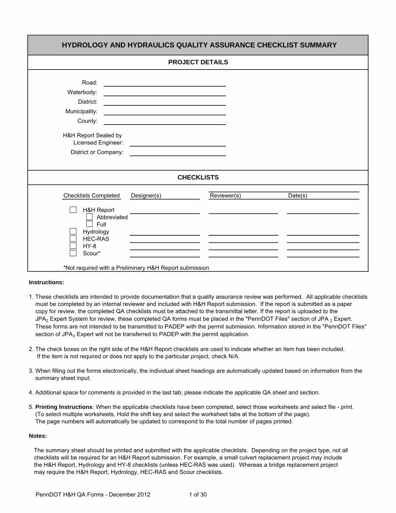
Road:Waterbody:
District:Municipality:
County:
H&H Report Sealed by Licensed Engineer:
District or Company:
Designer(s) Reviewer(s) Date(s)
H&H Report Abbreviated Full
HydrologyHEC-RASHY-8Scour*
*Not required with a Preliminary H&H Report submission
Instructions:
1. These checklists are intended to provide documentation that a quality assurance review was performed. All applicable checklists must be completed by an internal reviewer and included with H&H Report submission. If the report is submitted as a paper copy for review, the completed QA checklists must be attached to the transmittal letter. If the report is uploaded to the JPA2 Expert System for review, these completed QA forms must be placed in the "PennDOT Files" section of JPA 2 Expert. These forms are not intended to be transmitted to PADEP with the permit submission. Information stored in the "PennDOT Files" section of JPA2 Expert will not be transferred to PADEP with the permit application.
2. The check boxes on the right side of the H&H Report checklists are used to indicate whether an item has been included. If the item is not required or does not apply to the particular project, check N/A.
3. When filling out the forms electronically, the individual sheet headings are automatically updated based on information from the summary sheet input.
4. Additional space for comments is provided in the last tab; please indicate the applicable QA sheet and section.
5. Printing Instructions: When the applicable checklists have been completed, select those worksheets and select file - print. (To select multiple worksheets, Hold the shift key and select the worksheet tabs at the bottom of the page). The page numbers will automatically be updated to correspond to the total number of pages printed.
Notes:
The summary sheet should be printed and submitted with the applicable checklists. Depending on the project type, not allchecklists will be required for an H&H Report submission. For example, a small culvert replacement project may includethe H&H Report, Hydrology and HY-8 checklists (unless HEC-RAS was used). Whereas a bridge replacement projectmay require the H&H Report, Hydrology, HEC-RAS and Scour checklists.
Checklists Completed
HYDROLOGY AND HYDRAULICS QUALITY ASSURANCE CHECKLIST SUMMARY
PROJECT DETAILS
CHECKLISTS
PennDOT H&H QA Forms - December 2012 1 of 30

Project: District:Municipality: County:
Reviewer(s): Date:
YES NO N/AB.1.a. LOCATION MAP
Acceptable forms (one required):USGS quadrangle map (or map of equal detail) pageAerial photographs page
B.1.b. ENVIRONMENTAL CONCERNS1. PA Code Chapter 93 stream classification (check all that apply) page
WWF CWF MFTSF HQ* EV*
*Note if HQ or EV Stream, Antidegredation analysis may be required - see DM2, Chapter 13.72. PA Fish and Boat Classification (check all that apply)
Approved Trout Stream (stocked) Class A Wild Trout pageVerified Natural Reproduction None
B.1.c. STREAM BED MATERIAL pageType of material in stream bed from site inspection (i.e., sand, gravel, cobbles, etc.)
B.1.d. PHOTOGRAPHS pagea. Existing structure (upstream and downstream face)b. Upstream / downstream channel and floodplainc. Past floods (if available)d. Roadway station ahead and station back (recommended)e. Photo location map (recommended)
B.1.e. SITE INSPECTION RECORDS pageDates and other information relative to site inspection(s) made by designer date
B.2. HYDROLOGIC ANALYSIS a. Show drainage area above proposed crossing (note method of page
determining area)b. Include design discharge(s) per Section 10.6.E page
B.3. HYDRAULIC ANALYSIS a. The project is located in a FEMA mapped area?
If Yes is it a Detailed or Approximate area? __________________________(1) Original FIS study and flood map(s) provided page(2) Study is referenced in the text page(3) Was FEMA model obtained or documentation provided if unavailable?(4) Proposed structure encroaches on (check one): page
100-year floodplain (floodway fringe)100-year floodway neither
(5) Were existing flood elevations compared to FEMA's published? page(6) Were any differences in flood elevations > 0.5 ft explained? page
b/c. Existing versus proposed conditions:(1) velocities* page(2) backwater elevations* page(3) bridge opening sizes (i.e., area of hydraulic openings) page(4) Is there an increase in the proposed 100-year flood elevation?
* Recommend including a table to compare all cross sections for the PennDOT design event and the 100-year event
ABBREVIATED HYDROLOGIC AND HYDRAULIC REPORT CHECKLIST
DESCRIPTION ITEM PRESENT?
yes no
yes no
Section IPennDOT Abbrev H&H Report QA Form - December 2012 2 of 30

Project: District:Municipality: County:
Reviewer(s): Date:
YES NO N/A
ABBREVIATED HYDROLOGIC AND HYDRAULIC REPORT CHECKLIST
DESCRIPTION ITEM PRESENT?
c. Acceptable hydraulic methods for the site (check the method used)HEC-RAS (bridge and culvert design, water surface profiles)HY-8 (culvert design)Other List:
d. Estimated scour depths (refer to DM-4, Chapter 7) pagee. Riprap sizing for bank, pier, abutment, and/or culvert protection pagef. Construction measures (temp. stream crossings, causeways, roads, etc.) page
Comments or computations included page
B.4. RISK ASSESSMENT OR ANALYSIS*Narrative description of factors related to the 100-year flood pageNarrative description of factors related to the 2-year flood (temporary pageconditions)* Refer to Section 10.7.C.4 for the definition and additional requirements of a risk analysis
B.5. SUMMARY DATA SHEETComplete all information listed in the Summary Data Sheet (Figure 10.7.1) page(available for download from http://www.dot.state.pa.us/hh/Summary-Data-Sheet.Zip)Summary data matches the report tables, output/calculations, and TS&L
B.6. DRAWINGS AND FIGURESa. Roadway plans and profiles indicating the following information:
1. Locations of existing and/or proposed structures, stream pagechannels and wetlands- Structure or culvert plan showing plan and elevation view (Box culvert plans should show baffle layout)
2. 100-year floodplain boundary page3. Temporary stream crossing, access road, cofferdam, page
diversion facility, etc. 4. The magnitude, frequency and pertinent water surface page
elevation for PennDOT design and 100-year floodb. Plan drawing showing the location and orientation of all cross sections page
used in the hydraulic model (with scale, contours, and all importanthydraulic features) Cross-sections perpendicular to flood flow (minimum): page
Upstream (500 ft)Immediately upstream of proposed and/or existing crossingsImmediately downstream of proposed and/or existing crossingsDownstream (500 ft)
Items 6.c and 6.d below do not require separate drawings provided that the informationis available in the HEC-RAS model submitted with the reportc. Profile of stream showing bed slope, normal water surface, and flood page
water surface elevationsd. Cross section output of all cross sections used for backwater analysis pagee. Floodway maps and flood profiles from FEMA Flood Insurance Studies page
(when in a detailed FEMA study area)
ELECTRONIC FILESElectronic files for the hydrologic and hydraulic models (as applicable)
Section IPennDOT Abbrev H&H Report QA Form - December 2012 3 of 30

Project: District:Municipality: County:
Reviewer(s): Date:
YES NO N/AC.1.a. LOCATION MAP
Acceptable forms (one required):USGS quadrangle map (or map of equal detail) pageAerial photographs page
Required information:(1) Project location including proposed highway alignment(2) Drainage area(3) Label stream and direction, river reach studied
C.1.b. EXISTING STRUCTURES (IF APPLICABLE) page1. Identify existing hydraulic structures (by map), including upstream and
downstream of site2. Must describe:
(1) Type of structure, span lengths, pier orientation(2) Cross section beneath structure - stream clearance and skew
3. Compare stream and existing structure locations with the proposed crossing4. Indicate whether existing structures are to remain in place
C.1.c. FLOOD INFORMATION page1. Elevations of available highwater marks along the stream w/ dates of occurrence2. Critical flood elevations of interest (possible damage)3. Local testimony of flooding (if available) or structure performance (non-flooding)
per Section 10.7.C.1.i
C.1.d. ENVIRONMENTAL CONCERNS- PA Code Chapter 93 stream classification (check all that apply) page
WWF CWF MFTSF HQ* EV*
*Note if HQ or EV Stream, Antidegredation analysis may be required - see DM2, Chapter 13.7PA Fish and Boat Classification (check all that apply)
Approved Trout Stream (stocked) Class A Wild Trout pageVerified Natural Reproduction None
- Comments on other environmental concerns- Perennial, ephemeral, or intermittent stream?
C.1.e. HISTORY OF DRIFT, ICE AND STREAM BANK STABILITY page- Stability of stream banks (i.e., exposed soil, slumping, tilting trees, etc.)- Type of material in stream bed from site inspection (i.e., sand, gravel, cobbles, etc.)- History of ice accumulation or damage
C.1.f. PHOTOGRAPHS page- Existing structure (upstream and downstream face)- Upstream / downstream channel and floodplain- Past floods (if available)- Roadway station ahead and station back (recommended)- Photo location map (recommended)- Upstream and downstream structures
C.1.g. FACTORS AFFECTING WATER STAGES page1. High water from other streams2. Reservoirs (existing or proposed) and approximate date of construction3. Flood control projects and status (e.g., control structures, operator, operating policy)4. Other controls
HYDROLOGIC AND HYDRAULIC REPORT CHECKLIST
DESCRIPTION ITEM PRESENT?
Section IPennDOT H&H Report QA Form - December 2012 4 of 30
Project: District:Municipality: County:
Reviewer(s): Date:
YES NO N/A
HYDROLOGIC AND HYDRAULIC REPORT CHECKLIST
DESCRIPTION ITEM PRESENT?
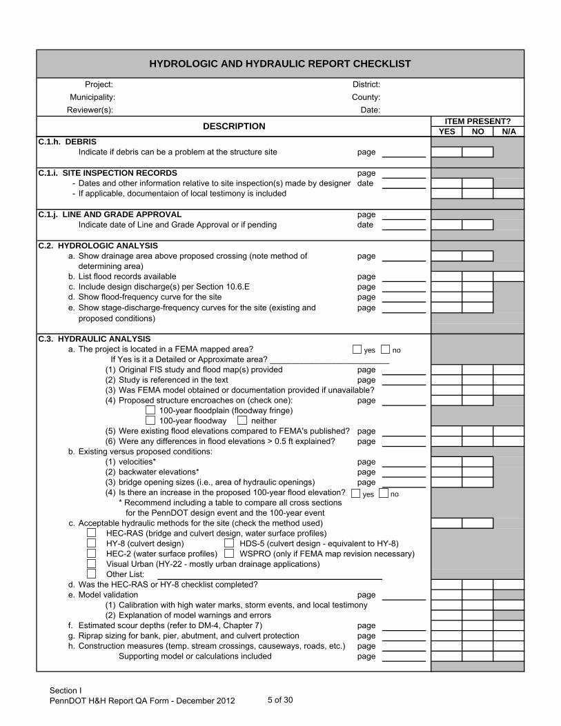
C.1.h. DEBRISIndicate if debris can be a problem at the structure site page
C.1.i. SITE INSPECTION RECORDS page- Dates and other information relative to site inspection(s) made by designer date- If applicable, documentaion of local testimony is included
C.1.j. LINE AND GRADE APPROVAL pageIndicate date of Line and Grade Approval or if pending date
C.2. HYDROLOGIC ANALYSIS a. Show drainage area above proposed crossing (note method of page
determining area)b. List flood records available pagec. Include design discharge(s) per Section 10.6.E paged. Show flood-frequency curve for the site pagee. Show stage-discharge-frequency curves for the site (existing and page
proposed conditions)
C.3. HYDRAULIC ANALYSIS a. The project is located in a FEMA mapped area?
If Yes is it a Detailed or Approximate area? __________________________(1) Original FIS study and flood map(s) provided page(2) Study is referenced in the text page(3) Was FEMA model obtained or documentation provided if unavailable?(4) Proposed structure encroaches on (check one): page
100-year floodplain (floodway fringe)100-year floodway neither
(5) Were existing flood elevations compared to FEMA's published? page(6) Were any differences in flood elevations > 0.5 ft explained? page
b. Existing versus proposed conditions:(1) velocities* page(2) backwater elevations* page(3) bridge opening sizes (i.e., area of hydraulic openings) page(4) Is there an increase in the proposed 100-year flood elevation?
* Recommend including a table to compare all cross sections for the PennDOT design event and the 100-year event
c. Acceptable hydraulic methods for the site (check the method used)HEC-RAS (bridge and culvert design, water surface profiles)HY-8 (culvert design) HDS-5 (culvert design - equivalent to HY-8)HEC-2 (water surface profiles) WSPRO (only if FEMA map revision necessary)Visual Urban (HY-22 - mostly urban drainage applications)Other List:
d. Was the HEC-RAS or HY-8 checklist completed?e. Model validation page
(1) Calibration with high water marks, storm events, and local testimony(2) Explanation of model warnings and errors
f. Estimated scour depths (refer to DM-4, Chapter 7) pageg. Riprap sizing for bank, pier, abutment, and culvert protection pageh. Construction measures (temp. stream crossings, causeways, roads, etc.) page
Supporting model or calculations included page
yes no
yes no
Section IPennDOT H&H Report QA Form - December 2012 5 of 30

Project: District:Municipality: County:
Reviewer(s): Date:
YES NO N/A
HYDROLOGIC AND HYDRAULIC REPORT CHECKLIST
DESCRIPTION ITEM PRESENT?
C.4. RISK ASSESSMENT OR ANALYSIS*Narrative description of factors related to: page
- 100-year flood- overtopping flood- 2-year flood for temporary conditions
* Refer to Section 10.7.C.4 for the definition and additional requirements of a risk analysis
C.5. SUMMARY DATA SHEETComplete all information listed in the Summary Data Sheet (Figure 10.7.1) page(available for download from http://www.dot.state.pa.us/hh/Summary-Data-Sheet.Zip)Summary data matches the report tables, output/calculations, and TS&L
C.6. DRAWINGS AND FIGURESa. Roadway plans and profiles indicating the following information:
1. Locations of existing and proposed structures, stream channels pageand wetlands- Structure or culvert plan showing plan and elevation view (Box culvert plans should show baffle layout)
2. Adjacent topographic features with key elevations or pagecontours shown- Profile drawing showing proposed structure and ground line
3. 100-year floodplain boundary page4. Flood easement (if required) page5. Temporary stream crossing, access road, cofferdam, page
diversion facility, etc.6. The magnitude, frequency and pertinent water surface page
elevation for specified floodsb. Profile of stream showing bed slope, normal water surface, and flood page
water surface elevationsc. Plan drawing showing the location and orientation of all cross sections page
used for backwater analysis (with scale, contours, and all important hydraulic features) Cross-sections perpendicular to flood flow (minimum): page
Upstream (500 ft)Immediately upstream of proposed and/or existing crossingsImmediately downstream of proposed and/or existing crossingsDownstream (500 ft)
d. Floodway maps and flood profiles from FEMA Flood Insurance Studies page(when in a detailed FEMA study area)
ELECTRONIC FILESElectronic files provided for hydrologic & hydraulic models (as applicable)
Section IPennDOT H&H Report QA Form - December 2012 6 of 30

Project: District:Municipality: County:
Reviewer(s): Date:
YES NO N/A1. FEMA CONSIDERATIONS
Is the proposed project in a detailed FEMA study area?If yes, are the following provided:
- Published FIS flows page- Is FEMA hydrologic method acceptable per DM-2, Chapter 10? page- Are FEMA flows compared with calculated flows using PennDOT acceptable methods?- Is FEMA's published 100-year flow included in the analysis?
Comments:
2. ACT 167
How were the flows developed in the Act 167?Were there flows provided in the vicinity of the project site?Have the flows been included for comparison to calculated flows? page
Comments:
3. DESIGN FLOODSPennDOT roadway classificationPennDOT design event (check one)
Is there a DEP approved Act 167 Stormwater Management Plan?
HYDROLOGY CHECKLISTQUALITY ASSURANCE REVIEW
DESCRIPTION
10-yr 25-yr 50-yrg ( )PADEP event (check one)
Comments:
4. HYDROLOGIC ANALYSISDrainage area at site (DA) is correct square milesApplicable hydrologic method used (check all that apply)
WRC method EFH2 (1 to 2000 ac)Rational method (up to 200 acres)* TR-55* (10 ac to 3.1 sq mi)PSU-IV (comparison only) WinTR-55 (1ac to 25 sq mi)USGS WRIR 2000-4189* USGS SIR 2008-5102*HEC-1/HEC-HMS* Other**
* Methods may be used within the Watershed Modeling System (WMS) program** Project Engineer should ensure that the model is appropriate and that approvals
are obtained from the Department
Was justification provided for the selection of the peak flow method? page
Comments:
Which method was chosen for the design flows?
10 yr 25 yr 50 yr25-yr (rural) 50-yr (suburban) 100-yr (urban)
Section IIPennDOT Hydrology QA Form - December 2012 7 of 30

Project: District:Municipality: County:
Reviewer(s): Date:
YES NO N/A
HYDROLOGY CHECKLISTQUALITY ASSURANCE REVIEW
DESCRIPTION
5. METHOD SELECTION DETAILSFill out the appropriate section below based on the hydrologic method(s) used in Section 4.
A. WRC Method (gage) pageUSGS gage #Gage location (i.e, town and stream/river name)Gage is on the same main stem as the project sitePrint out of gage record is includedDA at gage square milesDAsite is between 0.5 and 1.5 DAgage
Years of recordRecord is greater than 10 yearsHistoric peaks (i.e., not recorded by gage) are excludedRecord not partially influenced by regulation or diversion (e.g., reservoir, levee, etc.) Watershed characteristics consistent for entire record (e.g., landuse)Skew calculation method is appropriate (check one):
StationRegionalWeighted
If gage is not at project site, were flows correctly translated to the site?
Comments:
Return Period (yrs)
Qgage (cfs) Qsite (cfs)
Section IIPennDOT Hydrology QA Form - December 2012 8 of 30
Project: District:Municipality: County:
Reviewer(s): Date:
YES NO N/A
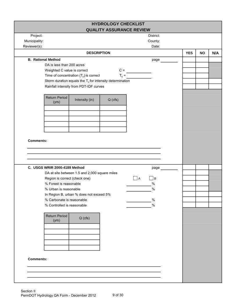
HYDROLOGY CHECKLISTQUALITY ASSURANCE REVIEW
DESCRIPTION
B. Rational Method pageDA is less than 200 acresWeighted C value is correct C = Time of concentration (Tc) is correct Tc =Storm duration equals the Tc for intensity determination Rainfall intensity from PDT-IDF curves
Comments:
Return Period (yrs) Intensity (in) Q (cfs)
C. USGS WRIR 2000-4189 Method pageDA at site between 1.5 and 2,000 square milesRegion is correct (check one) % Forest is reasonable %% Urban is reasonable %In Region B, urban % does not exceed 5%% Carbonate is reasonable %% Controlled is reasonable %
Comments:
Return Period (yrs) Q (cfs)
A B
Section IIPennDOT Hydrology QA Form - December 2012 9 of 30

Project: District:Municipality: County:
Reviewer(s): Date:
YES NO N/A
HYDROLOGY CHECKLISTQUALITY ASSURANCE REVIEW
DESCRIPTION
D. USGS SIR 2008-5102 Method pageDA at site between 1.0 and 2,000 square milesRegion is correct (check one) % Forest is reasonable %% Urban is reasonable %% Carbonate is reasonable %% Storage is reasonable* %*surface area of lakes, ponds, wetlands, etc.Mean basin elevation is is correct (Region 3)
Comments:
Return Period (yrs) Q (cfs)
1 2 3 4
Section IIPennDOT Hydrology QA Form - December 2012 10 of 30

Project: District:Municipality: County:
Reviewer(s): Date:
YES NO N/A
HYDROLOGY CHECKLISTQUALITY ASSURANCE REVIEW
DESCRIPTION
E. PSU IV (Comparison Method Only) pageDA at site between 1.5 and 150 square milesRegion is correct (check one)Standard Deviation is correctSkew Coefficient is correctDivide Elevation is correct feet% Forest is reasonable %Adjustment for carbonate area appliedIndicate other adjustments applied
Comments:
Return Period (yrs) Q (cfs)
1 2 3 4
Section IIPennDOT Hydrology QA Form - December 2012 11 of 30

Project: District:Municipality: County:
Reviewer(s): Date:
YES NO N/A
HYDROLOGY CHECKLISTQUALITY ASSURANCE REVIEW
DESCRIPTION
F. TR-55 Method / WinTr-55 pageDA at site is between 10 and 2,000 acres (< 3.1 square miles) for TR-55DA at site is between 1 acre and 25 square miles for WinTR-55Note if multiple drainage areas are used, attach additional sheets for CN, etc.CN calculated correctly CN = Time of concentration (Tc) calculated correctly hrs (0.1<Tc<10 hr) Sheet flow length no greater than 100' feetShallow concentrated flow length appropriate feetChannel flow length appropriate feetRainfall from PDT-IDF curves (24-hour duration)PDT-IDF Curve or SCS Type II 24-hr rainfall distribution used
Return Period (yrs) Rainfall (in) Q (cfs)
Comments:
Section IIPennDOT Hydrology QA Form - December 2012 12 of 30

Project: District:Municipality: County:
Reviewer(s): Date:
YES NO N/A
HYDROLOGY CHECKLISTQUALITY ASSURANCE REVIEW
DESCRIPTION
G. EFH2 Method pageDA at site between 1 and 2,000 acres (< 3.1 square miles)CN calculated correctly CN = Urban % does not exceed 10% %Hydraulic length is between 200 and 26,000 feet feetAverage watershed slope, Y %Y is the average overland slope between drainage divide and stream channelRainfall from PDT-IDF curves (24-hour duration)PDT-IDF Curve or SCS Type II 24-hr rainfall distribution used
Comments:
Return Period (yrs) Rainfall (in) Q (cfs)
Section IIPennDOT Hydrology QA Form - December 2012 13 of 30
Project: District:Municipality: County:
Reviewer(s): Date:
YES NO N/A
HYDROLOGY CHECKLISTQUALITY ASSURANCE REVIEW
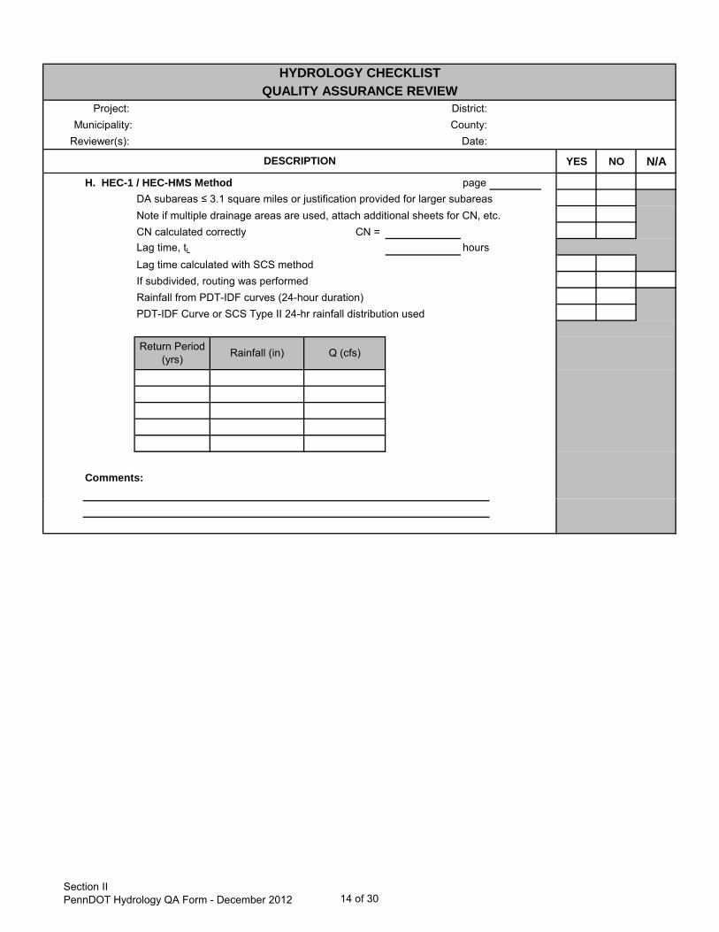
DESCRIPTION
H. HEC-1 / HEC-HMS Method pageDA subareas ≤ 3.1 square miles or justification provided for larger subareasNote if multiple drainage areas are used, attach additional sheets for CN, etc.CN calculated correctly CN = Lag time, tL hoursLag time calculated with SCS methodIf subdivided, routing was performedRainfall from PDT-IDF curves (24-hour duration)PDT-IDF Curve or SCS Type II 24-hr rainfall distribution used
Comments:
Return Period (yrs) Rainfall (in) Q (cfs)
Section IIPennDOT Hydrology QA Form - December 2012 14 of 30

Project: District:Municipality: County:
Reviewer(s): Date:
YES NO N/A
HYDROLOGY CHECKLISTQUALITY ASSURANCE REVIEW
DESCRIPTION
I. Other Method pageCalculations includedMethod appropriate for locationRationale / justification provided
Comments:
Return Period (yrs) Rainfall (in) Q (cfs)
Section IIPennDOT Hydrology QA Form - December 2012 15 of 30
Project: District:Municipality: County:
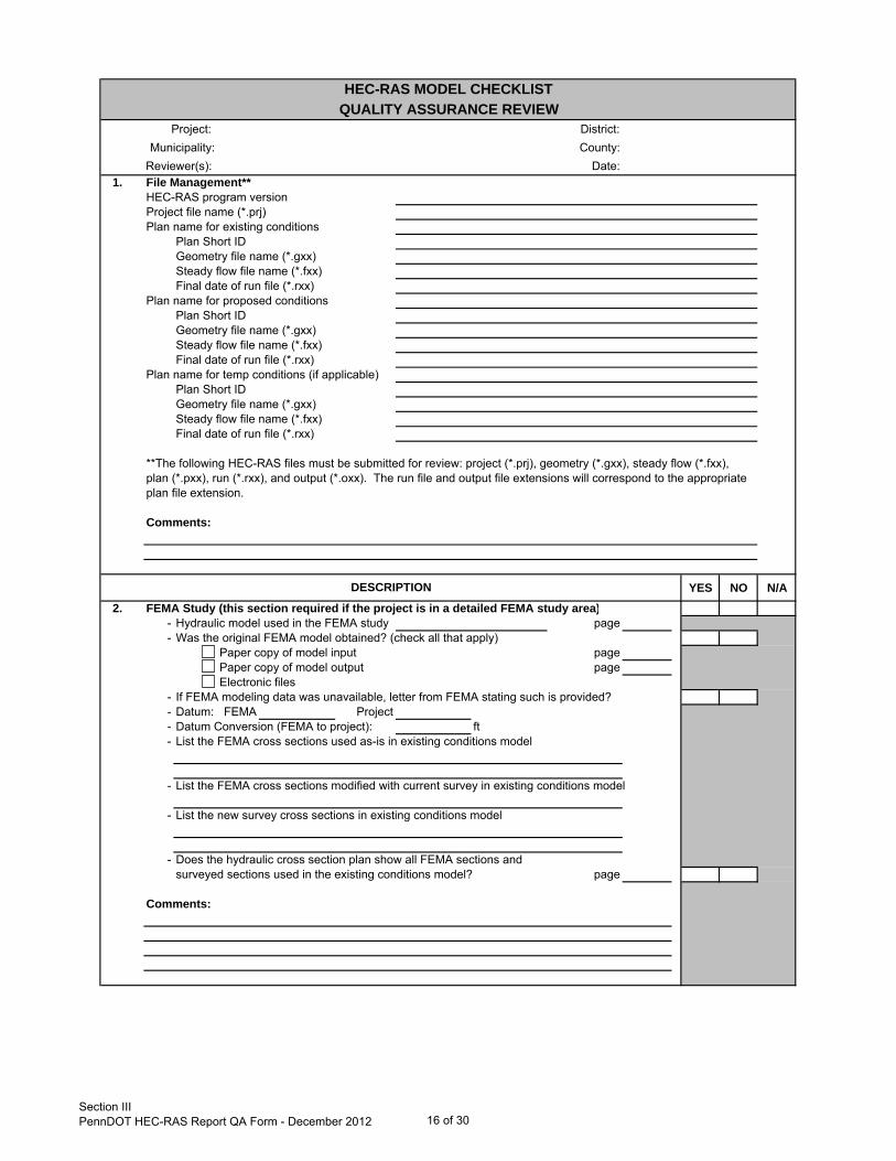
Reviewer(s): Date:1. File Management**
HEC-RAS program versionProject file name (*.prj)Plan name for existing conditions
Plan Short IDGeometry file name (*.gxx)Steady flow file name (*.fxx)Final date of run file (*.rxx)
Plan name for proposed conditionsPlan Short IDGeometry file name (*.gxx)Steady flow file name (*.fxx)Final date of run file (*.rxx)
Plan name for temp conditions (if applicable)Plan Short IDGeometry file name (*.gxx)Steady flow file name (*.fxx)Final date of run file (*.rxx)
**The following HEC-RAS files must be submitted for review: project (*.prj), geometry (*.gxx), steady flow (*.fxx),plan (*.pxx), run (*.rxx), and output (*.oxx). The run file and output file extensions will correspond to the appropriateplan file extension.
Comments:
YES NO N/A2. FEMA Study (this section required if the project is in a detailed FEMA study area)
- Hydraulic model used in the FEMA study page- Was the original FEMA model obtained? (check all that apply)
Paper copy of model input pagePaper copy of model output pageElectronic files
- If FEMA modeling data was unavailable, letter from FEMA stating such is provided?- Datum: FEMA Project- Datum Conversion (FEMA to project): ft- List the FEMA cross sections used as-is in existing conditions model
- List the FEMA cross sections modified with current survey in existing conditions model
- List the new survey cross sections in existing conditions model
- Does the hydraulic cross section plan show all FEMA sections and surveyed sections used in the existing conditions model? page
Comments:
HEC-RAS MODEL CHECKLISTQUALITY ASSURANCE REVIEW
DESCRIPTION
Section IIIPennDOT HEC-RAS Report QA Form - December 2012 16 of 30

Project: District:Municipality: County:
Reviewer(s): Date:
HEC-RAS MODEL CHECKLISTQUALITY ASSURANCE REVIEW
YES NO N/A3. Steady Flow Data
Boundary Conditions Upstream DownstreamNormal depth S= S=Known WS WS Elev= WS Elev=Critical depthRating curve source= source=
- Are the boundary conditions appropriate?- Are the same boundary conditions used in the existing and proposed models?- If applicable, was a known WS used for the FEMA published flow?
Discharge Information (see also Hydrology checklist)- 100-year, DEP and PennDOT design events were modeled- Temporary conditions event modeled year- Flows for the modeled events match peak flows in the H&H Report- Flow change(s) reflects tributary location(s)
Comments:
4. Geometric DataPlan Information / River System Schematic
- Plan showing the location and orientation of all cross sections provided(with scale, contours, and all important hydraulic features) page
- Number of reaches- Number of junctions- Cross section numbers increase from downstream to upstream
Cross Section Geometry- Cross sections extend across 100-year floodplain- Cross sections are perpendicular to flow direction (except at bounding structure sections)- Cross sections do not overlap- Cross section data is entered from left to right (looking downstream)- Left and right bank stations: - are reasonable
- have consistent elevations- Reach lengths are correct- Manning's n values are reasonable (Table 3.1 in Reference 1)- Contraction/expansion coefficients are reasonable
(contr = 0.3, exp = 0.5 bounding structure sections)- Ineffective flow areas reflect contraction / expansion reach near hydraulic structure
(Reference 2)- Ineffective flow areas in overbanks are used where appropriate- Levees are used where appropriate- Blocked obstructions are used where appropriate
Comments:
DESCRIPTION
Section IIIPennDOT HEC-RAS Report QA Form - December 2012 17 of 30

Project: District:Municipality: County:
Reviewer(s): Date:
HEC-RAS MODEL CHECKLISTQUALITY ASSURANCE REVIEW
YES NO N/AGeometric Data continued
4a. Bridge Geometry*- Plan with high/low chord elevations included page- Bridge cross section (E) (P)- Bounding bridge sections are at or beyond the embankment toe and parallel to each other- High chord (max.) (E) (P)- Low chord (min.) (E) (P)- High/low chords match the report/drawings- Bridge width (E) (P)- Bridge widths match the report/drawings- Distance to US section (E) (P)- US distances match the hydraulic section plan- Number of spans (E) (P)- Normal clear span length(s) (E) (P)- Bridge normal clear span lengths match the report/drawings- Number of piers (E) (P)- Existing pier centerline(s), width(s) and elevation(s) are correct- Proposed pier centerline(s), width(s) and elevation(s) are correct- Ineffective areas "turn off" when weir flow passes over bridge- Minimum weir flow elevation is reasonable- Bridge modeling methods Existing Proposed
Low flowHigh flow
- Methods are appropriate per Reference 1
* Check for existing (E) and proposed (P) structure; low chord elevations and normal clear span lengths are not applicable to arch structures.
Comments:
DESCRIPTION
Section IIIPennDOT HEC-RAS Report QA Form - December 2012 18 of 30

Project: District:Municipality: County:
Reviewer(s): Date:
HEC-RAS MODEL CHECKLISTQUALITY ASSURANCE REVIEW
YES NO N/AGeometric Data continued
4b. *Culvert Geometry- Plan with inverts elevations included page
- Structure cross section (E) (P)- Bounding culvert cross sections are at or beyond the embankment toe- Ineffective areas "turn off" when weir flow passes over road- Minimum weir flow elevation is reasonable
Existing Proposed- Number of barrels- Shape
DiameterSpan x Rise
- Spans/diameters are correct- Chart #- Scale #- Chart and Scale match the culvert type and entrance conditions- Distance to US section ft ft- US distances match the hydraulic section plan- Culvert length ft ft- Culvert lengths match the hydraulic section and structure plans- Entrance loss coeff- Exit loss coeff- Loss coefficients are appropriate for entrance/exit conditions- Manning's n for top- Manning's n for bottom- Manning's n for top and bottom are appropriate- Depth to use bottom n- Depth blocked- Blocked depth reflects the depressed depth for fish passage- US invert elevation ft ft- DS invert elevation ft ft- Invert elevations match the report/drawings- High chord (max.) ft ft- High chords match structure drawings
* Check for existing (E) and proposed (P) structure
Comments:
DESCRIPTION
Section IIIPennDOT HEC-RAS Report QA Form - December 2012 19 of 30

Project: District:Municipality: County:
Reviewer(s): Date:
HEC-RAS MODEL CHECKLISTQUALITY ASSURANCE REVIEW
YES NO N/AGeometric Data continued
4c. *Roadway Profile- Roadway profile plan provided page- Roadway stations are entered from left to right (looking downstream)- Roadway (high chord) stations and elevations match drawings (exist and prop)- Highest roadway elevation is coded as the US side so that weir flow is correctly calculated.
* Check for existing (E) and proposed (P) structure
Comments:
4d. Temporary Conditions- Temporary fill and/or structure(s) proposed in the channel? (check all that apply)
Cofferdam (e.g., sheet piling, Jersey barrier, sand bags)CausewayTemporary roadOther
- Dimension and locations match report and E&S Plan page- Geometry reflects worst-case construction scenario (i.e., generally the most obstructed area)
Comments:
5. Plan FileFlow Regime
SubcriticalSupercriticalMixed
- If subcritical only, is the Froude number < 1.0 at every section?- If supercritical only, is the Froude number > 1.0 at every section?
Comments:
DESCRIPTION
Section IIIPennDOT HEC-RAS Report QA Form - December 2012 20 of 30

Project: District:Municipality: County:
Reviewer(s): Date:
HEC-RAS MODEL CHECKLISTQUALITY ASSURANCE REVIEW
YES NO N/A6. Output
Existing versus Proposed Output- Water surface profiles are in the correct order in the cross section output- Is the existing low chord elevation equal to or below the proposed?- Hydraulic opening area stated (sf) Exist. (sf) Prop.- Is the proposed opening area equal to or larger than the existing?- Errors, warnings, and notes reviewed and discussed page- Are there increases at any cross section for the proposed 100-year event?- Existing and proposed HEC-RAS cross section plot output are included page- Existing and proposed HEC-RAS profile output are included page
(table & plot)- Output shows 100-year, DEP and PennDOT design events
Comments:
Temporary Conditions Output- The H&H report states that the year event does not overtop the temporary measures- The magnitude and extent of temporary increases are quantified page- Are the temporary increases contained within the channel? page- Do the temporary wsels tie in to existing wsels within the study limits? page
Comments:
References
2 Hydrologic Engineering Center. 1995. RD-42, Flow Transitions in Bridge Backwater Analysis, U.S. Army Corps of Engineers, Davis, CA.
DESCRIPTION
1 Hydrologic Engineering Center. 2002. HEC-RAS, River Analysis System Hydraulic Reference Manual. U.S. Army Corps of Engineers, Davis, CA.
Section IIIPennDOT HEC-RAS Report QA Form - December 2012 21 of 30
Project: District:Municipality: County:
Reviewer(s): Date:
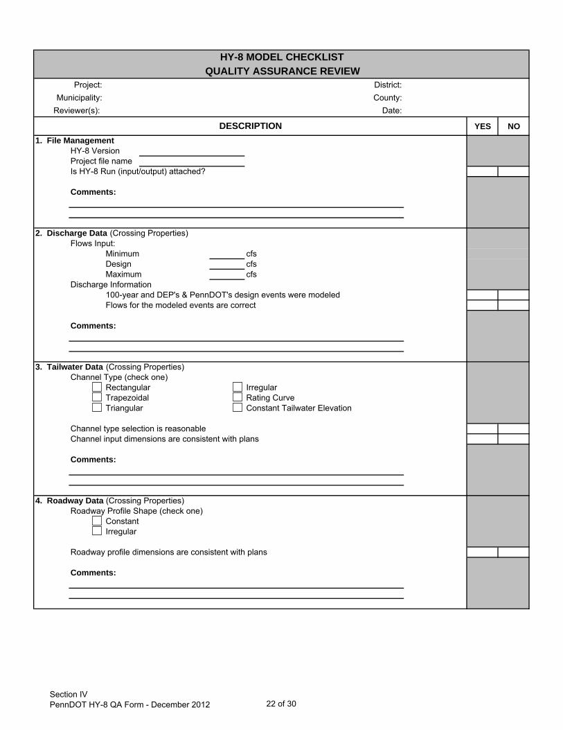
YES NO1. File Management
HY-8 Version Project file nameIs HY-8 Run (input/output) attached?
Comments:
2. Discharge Data (Crossing Properties)Flows Input:
Minimum cfsDesign cfsMaximum cfs
Discharge Information100-year and DEP's & PennDOT's design events were modeledFlows for the modeled events are correct
Comments:
3. Tailwater Data (Crossing Properties)Channel Type (check one)
Rectangular IrregularTrapezoidal Rating CurveTriangular Constant Tailwater Elevation
Channel type selection is reasonableChannel input dimensions are consistent with plans
Comments:
4. Roadway Data (Crossing Properties)Roadway Profile Shape (check one)
ConstantIrregular
Roadway profile dimensions are consistent with plans
Comments:
HY-8 MODEL CHECKLISTQUALITY ASSURANCE REVIEW
DESCRIPTION
Section IVPennDOT HY-8 QA Form - December 2012 22 of 30
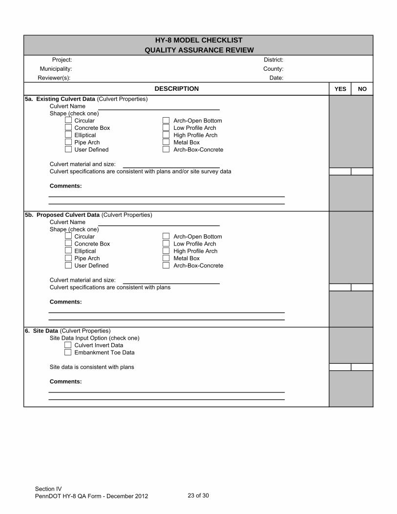
Project: District:Municipality: County:
Reviewer(s): Date:
YES NO
HY-8 MODEL CHECKLISTQUALITY ASSURANCE REVIEW
DESCRIPTION5a. Existing Culvert Data (Culvert Properties)
Culvert NameShape (check one)
Circular Arch-Open BottomConcrete Box Low Profile ArchElliptical High Profile ArchPipe Arch Metal BoxUser Defined Arch-Box-Concrete
Culvert material and size:Culvert specifications are consistent with plans and/or site survey data
Comments:
5b. Proposed Culvert Data (Culvert Properties)Culvert NameShape (check one)
Circular Arch-Open BottomConcrete Box Low Profile ArchElliptical High Profile ArchPipe Arch Metal BoxUser Defined Arch-Box-Concrete
Culvert material and size:Culvert specifications are consistent with plans
Comments:
6. Site Data (Culvert Properties)Site Data Input Option (check one)
Culvert Invert DataEmbankment Toe Data
Site data is consistent with plans
Comments:
Section IVPennDOT HY-8 QA Form - December 2012 23 of 30
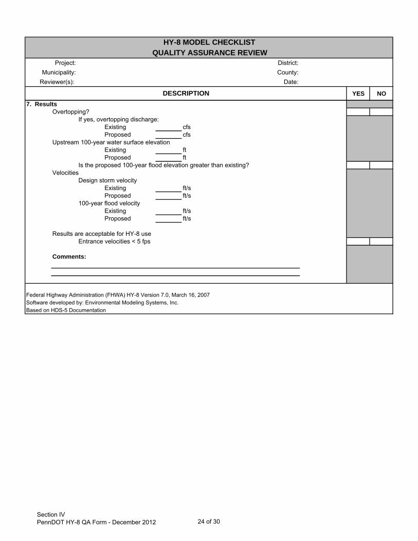
Project: District:Municipality: County:
Reviewer(s): Date:
YES NO
HY-8 MODEL CHECKLISTQUALITY ASSURANCE REVIEW
DESCRIPTION7. Results
Overtopping?If yes, overtopping discharge:
Existing cfsProposed cfs
Upstream 100-year water surface elevationExisting ftProposed ft
Is the proposed 100-year flood elevation greater than existing?Velocities
Design storm velocityExisting ft/sProposed ft/s
100-year flood velocityExisting ft/sProposed ft/s
Results are acceptable for HY-8 useEntrance velocities < 5 fps
Comments:
Federal Highway Administration (FHWA) HY-8 Version 7.0, March 16, 2007Software developed by: Environmental Modeling Systems, Inc. Based on HDS-5 Documentation
Section IVPennDOT HY-8 QA Form - December 2012 24 of 30

Project: District:Municipality: County:
Reviewer(s): Date:
YES NO N/A
1. Streambed Particle Size- D50 in = ft
Typical D50 Values:Clay and siltSandGravelCobbles
- Method used to determine D50
visual inspection sieve analysispebble count core boring* (see notes on applicability below)
- Location of streambed sample- Streambed material description page- Is bedrock visible?- Is D50 appropriate for studied reach?- Evidence of long-term streambed elevation change (aggradation or degradation)?* For limitations on core borings use see requirements in DM-4, Chapter 7. Also for most
PA streams core borings may underestimate the size of the streambed material. If the approximate D100 particle size is less than the core diameter and the sample is taken in the stream channel, the core borings may provide a reasonable D50 for the armor layer.
64 - 250 mm
0.062 - 2.00 mm 0.002 - 0.08 in2 - 64 mm 0.08 - 2.5 in
2.5 - 10 in
SCOUR ANALYSIS & RIPRAP SIZING CHECKLISTQUALITY ASSURANCE REVIEW
0.00024 - 0.062 mm
DESCRIPTION
Comments:
2. Contraction ScourHEC-RAS Sections - fill in the appropriate information from the proposed HEC-RAS model
Comments:
Key1. Upstream uncontracted cross section (XS output)2. Internal bridge cross section (BR U or BR D in HEC-RAS output)3. Upstream bounding cross section (XS output)
XS: ________
XS: ________XS: ________
Length = _______ ft
Length = _______ ft
Section VPennDOT Scour QA Form - December 2012 25 of 30
Project: District:Municipality: County:
Reviewer(s): Date:
YES NO N/A
SCOUR ANALYSIS & RIPRAP SIZING CHECKLISTQUALITY ASSURANCE REVIEW
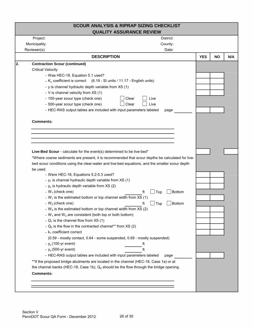
DESCRIPTION2. Contraction Scour (continued)
Critical Velocity- Was HEC-18, Equation 5.1 used?-- y is channel hydraulic depth variable from XS (1)- V is channel velocity from XS (1)- 100-year scour type (check one) Clear Live- 500-year scour type (check one) Clear Live- HEC-RAS output tables are included with input parameters labeled page
Comments:
Live-Bed Scour - calculate for the event(s) determined to be live-bed*
*Where coarse sediments are present, it is recommended that scour depths be calculated for live-bed scour conditions using the clear-water and live-bed equations, and the smaller scour depthbe used.
- Were HEC-18, Equations 5.2-5.3 used?
Ku coefficient is correct (6.19 - SI units / 11.17 - English units)
Were HEC 18, Equations 5.2 5.3 used?- y1 is channel hydraulic depth variable from XS (1)- yo is hydraulic depth variable from XS (2)- W1 (check one) ft- W1 is the estimated bottom or top channel width from XS (1)- W2 (check one) ft- W2 is the estimated bottom or top channel width from XS (2)- W1 and W2 are consistent (both top or both bottom)- Q1 is the channel flow from XS (1)- Q2 is the flow in the contracted channel** from XS (2)- k1 coefficient correct
(0.59 - mostly contact, 0.64 - some suspended, 0.69 - mostly suspended)- ys (100-yr event) ft- ys (500-yr event) ft- HEC-RAS output tables are included with input parameters labeled page
the channel banks (HEC-18, Case 1b), Q2 should be the flow through the bridge opening.
Comments:
**If the proposed bridge abutments are located in the channel (HEC-18, Case 1a) or at
BottomTop
Top Bottom
Section VPennDOT Scour QA Form - December 2012 26 of 30
Project: District:Municipality: County:
Reviewer(s): Date:
YES NO N/A
SCOUR ANALYSIS & RIPRAP SIZING CHECKLISTQUALITY ASSURANCE REVIEW
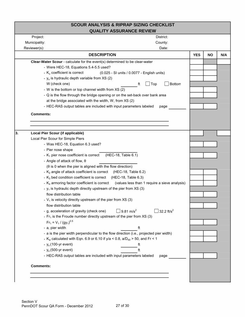
DESCRIPTIONClear-Water Scour - calculate for the event(s) determined to be clear-water
- Were HEC-18, Equations 5.4-5.5 used?- Ku coefficient is correct (0.025 - SI units / 0.0077 - English units)- yo is hydraulic depth variable from XS (2)
W (check one) ft- W is the bottom or top channel width from XS (2)- Q is the flow through the bridge opening or on the set-back over bank area
at the bridge associated with the width, W, from XS (2)- HEC-RAS output tables are included with input parameters labeled page
Comments:
3. Local Pier Scour (if applicable)Local Pier Scour for Simple Piers
- Was HEC-18, Equation 6.3 used?- Pier nose shape- K1 pier nose coefficient is correct (HEC-18, Table 6.1)- Angle of attack of flow, θ
(θ is 0 when the pier is aligned with the flow direction)
BottomTop
- K2 angle of attack coefficient is correct (HEC-18, Table 6.2)- K3 bed condition coefficient is correct (HEC-18, Table 6.3)- K4 armoring factor coefficient is correct (values less than 1 require a sieve analysis)- y1 is hydraulic depth directly upstream of the pier from XS (3)
flow distribution table- V1 is velocity directly upstream of the pier from XS (3)
flow distribution table- g, acceleration of gravity (check one) 9.81 m/s2 32.2 ft/s2
- Fr1 is the Froude number directly upstream of the pier from XS (3)
Fr1 = V1 / (gy1)0.5
- a, pier width ft- a is the pier width perpendicular to the flow direction (i.e., projected pier width)- Kw calculated with Eqn. 6.9 or 6.10 if y/a < 0.8, a/D50 > 50, and Fr < 1- ys (100-yr event) ft- ys (500-yr event) ft- HEC-RAS output tables are included with input parameters labeled page
Comments:
Section VPennDOT Scour QA Form - December 2012 27 of 30

Project: District:Municipality: County:
Reviewer(s): Date:
YES NO N/A
SCOUR ANALYSIS & RIPRAP SIZING CHECKLISTQUALITY ASSURANCE REVIEW
DESCRIPTION3. Local Pier Scour (continued)
Pressure Flow Scour (Vertical Contraction Scour) *Pressure flow scour should be calculated for all events that submerge the low chord
- Hb, distance from average streambedelevation to low chord of bridge ft
- Hb dimension calculations provided/appropriate?- y1 is hydraulic depth variable from XS (3)- y1 is greater than Hb for what events?*- Va is the average velocity inside the bridge from XS (2) BR U- Was HEC-18, Equation 6.21 used?
y1
Hb
ys
- ys (100-yr event) ft- ys (500-yr event) ft- HEC-RAS output tables are included with input parameters labeled page
Comments:
Section VPennDOT Scour QA Form - December 2012 28 of 30

Project: District:Municipality: County:
Reviewer(s): Date:
YES NO N/A
SCOUR ANALYSIS & RIPRAP SIZING CHECKLISTQUALITY ASSURANCE REVIEW
DESCRIPTION4. Total Scour
- If live-bed contraction scour depths are limited by streambed armoring,was the lesser of the clear-water and live-bed contraction scour depths used?
- If multi-layered riprap protection is proposed for the piers, was the localpier scour depth reduced by 50%?
- If the structure has piers, was the total pier scour depth calculated as the sum of the contraction scour, pressure scour, and adjusted local pier scour depths?
- Scour envelope is illustrated on the HEC-RAS bridge section page- Total scour depths are included in the H&H Report page- If any aggradation or degradation was indicated in bridge inspection reports
was it included with total scour?- Scour depths were calculated for the temporary bridge (25-year event) per DM-4, Chap 5.
*Note: Per DM-4, Chapter 7 local abutment scour calculations are not requiredwhen the substructure is protected with multi-layered riprap protection.
Comments:
5. Riprap Sizing- Unfactored velocities
AbutmentV ft/s V ft/
Piers V100 ft/s V100 ft/s V500 ft/s V500 ft/s
- For abutments, V is the BR Open Vel variable for the velocity inside the bridge- For piers, V is the avg upstream velocity in the section upstream of the piers - XS (3)- HEC-RAS bridge output table shows inside bridge velocity page- What event has the highest velocity inside the bridge?- Was the highest velocity used?**
Abutments- Was the 1.8 safety factor applied to the velocity before sizing the riprap?- Riprap size meets DM-4 Chapter 7 requirements R -
Piers- Was the 1.5 safety factor applied to the velocity before sizing the riprap?- Riprap size meets DM-4 Chapter 7 requirements R -
Temporary Bridge- Was the 1.8 safety factor applied to the 25-year velocity per DM-4, Chapter 5?- Riprap size meets DM-4 Chapter 7 requirements R -
Comments:
US Department of Transportation, FHWA. Hydraulic Engineering Circular No. 18 (HEC-18), Evaluating Scour at Bridges, 4th Edition. May 2001.
**Note: Per DM-4 Chapter 7, riprap has to be designed to withstand the 500-year velocity only when the 500-year scour depth is below the bottom of footing elevation. If a lower event has the highest velocity inside the bridge, it should be used for riprap sizing.
Section VPennDOT Scour QA Form - December 2012 29 of 30

Project: District:Municipality: County:
Checklist Section
Checklist Section
Checklist Section
Checklist Section
ADDITIONAL COMMENTSQUALITY ASSURANCE REVIEW
Checklist Section
Checklist Section
Checklist Section
Additional CommentsPennDOT H&H QA Forms - December 2012 30 of 30


![Class 6 [Z] SQF | 13m NCO | Level-l | Set-B](https://img.dokumen.tips/doc/110x75/587740b31a28ab13448b4ef6/class-6-z-sqf-13m-nco-level-l-set-b.jpg)


