Embed Size (px)
Citation preview

Revised —4/25/2019
Chapter 1
Selective Noncatalytic Reduction
John L. Sorrels
Air Economics Group
Health and Environmental Impacts Division
Office of Air Quality Planning and Standards
U.S. Environmental Protection Agency
Research Triangle Park, NC 27711
David D. Randall, Carrie Richardson Fry, and Karen S. Schaffner
RTI International
Research Triangle Park, NC 27709
April 2019

EPA Form 2220-1.(Rev. 4-77) PREVIOUS EDITION IS OBSOLETE
DISCLAIMER
This document includes references to specific companies, trade names and commercial
products. Mention of these companies and their products in this document is not intended to
constitute an endorsement or recommendation by the U.S. Environmental Protection Agency.

EPA Form 2220-1.(Rev. 4-77) PREVIOUS EDITION IS OBSOLETE
Contents
1. Selective Noncatalytic Reduction .......................................................................................... 1-1 1.1 Introduction ................................................................................................................... 1-1
1.2 Process Description ....................................................................................................... 1-9 1.2.1 Reduction Chemistry ...................................................................................... 1-10 1.2.2 Reagents .......................................................................................................... 1-11 1.2.3 SNCR Performance Parameters ...................................................................... 1-13 1.2.4 SNCR System ................................................................................................. 1-20
1.2.5 Other Considerations ...................................................................................... 1-26 1.2.6 New SNCR Approaches ................................................................................. 1-29
1.3 Design Parameters ...................................................................................................... 1-31 1.3.1 Design Parameters for Study-Level Estimates ............................................... 1-32
1.3.2 Design Parameters for Detailed/Performance Specifications ......................... 1-39 1.4 Cost Analysis .............................................................................................................. 1-41
1.4.1 Total Capital Investment ................................................................................. 1-42 1.4.2 Total Annual Costs ......................................................................................... 1-49
1.5 Example Problem ........................................................................................................ 1-55
1.5.1 Design Parameter Example ............................................................................. 1-56 1.5.2 Cost Estimation Example ................................................................................ 1-59
References ............................................................................................................................ 1-62
Chapter 1 – Selective Noncatalytic Reduction
1-1
1. SELECTIVE NONCATALYTIC REDUCTION
1.1 Introduction
Selective noncatalytic reduction (SNCR) is a post combustion emissions control
technology for reducing NOx by injecting an ammonia type reactant into the furnace at a properly
determined location. This technology is often used for mitigating NOx emissions since it requires
a relatively low capital expense for installation, albeit with relatively higher operating costs.
Japan originally developed SNCR for oil and gas units in the 1970s; Western Europe followed
by applying the science to coal fired units in the late 1980s and the U.S electric power sector
began installations on coal plants in the early 1990s. More than 45 gigawatts of coal-fired power
capacity in the U.S. now have SNCR.1 SNCR is now used beyond the electric power industry,
and is currently being used to control NOx emissions from a multitude of combustion sources,
including industrial boilers, electric utility steam generators, thermal incinerators, cement kilns,
pulp and paper power boilers, steel industry process units, refinery process units, and municipal
solid waste energy recovery facilities [1, 2, 3]. It is being used on industrial boilers covering a
wide range of sizes from <50 MMBtu/hr to more than 800 MMBtu/hr [2]. SNCR is also being
used on a wide range of sizes of utility boilers from <50 MW to more than 900 MW. More than
half of utility boilers with SNCR are relatively small (<50 – 200 MW) but about 24 percent are
larger than 300 MW.1 Over 70 percent of the utility boilers using SNCR burn coal as the primary
fuel and most of the others burn biomass, but the other types of combustion sources are burning a
wide range of materials [2].1 SNCR can be applied as a standalone NOx control or with other
technologies such as combustion controls. The SNCR system can be designed for seasonal or
year-round operations.
Reported SNCR reduction efficiencies vary over a wide range. Temperature, residence
time, type of NOx reducing reagent, reagent injection rate, uncontrolled NOx level, distribution of
the reagent in the flue gas, and CO and O2 concentrations all affect the reduction efficiency of
the SNCR [2]. Tables 1.1 and 1.2 and Figures 1.1a, 1.1b, and 1.1c summarize emission
reductions for SNCR applications in a variety of industries [2]. Findings based on review of
these data are as follows:
• Although installation of urea-based systems is more common than ammonia-based
deployments, operating data reveal higher NOx reductions occur with ammonia reagent.
Table 1.1 shows the median (as a measure of average) reductions for urea-based SNCR
systems in various industry source categories range from 25 to 60 percent, while median
reductions for ammonia-based SNCR systems range from 61 to 65 percent. Note that
most of the boilers with ammonia-based SNCR systems that are fired with solid fuels are
fired with wood or municipal solid waste. Figure 1.1b shows nearly all ammonia-based
systems have reduction efficiencies greater than 40 percent, while several urea-based
systems have lower reduction efficiencies.
1 Spreadsheet of information provided to EPA's Clean Air Market Division from query of SNL Energy data on
1/22/2015.

Chapter 1 – Selective Noncatalytic Reduction
1-2
Table 1.1: Summary of NOx Reduction Efficiencies Obtained Using SNCR on Different
Types of Boilers in the U.S. [2]
Type of source category Fuel
NOx reduction reagent
Average boiler size
Median NOx reduction (%)
Electric utility Coal Urea 320 MW 25
Co-generation Primarily wood, some coal, biomass, and tires
Urea 360 MMBtu/hr 50
Pulp & paper (P&P) Primarily bark and wood waste, supplemented with a variety of other fuels
Urea 410 MMBtu/hr 50
Municipal waste combustion (MWC)
Municipal solid waste (MSW) Urea 270 MMBtu/hr 37
Refinery CO boilers Typically refinery fuel gas Urea 320 MMBtu/hr 60
Miscellaneous combustion units
Primarily wood, MSW, or coal Ammonia 400 MMBtu/hr 65
Miscellaneous combustion units
Primarily crude oil or gas Ammonia 110 MMBtu/hr 61
Table 1.2: SNCR NOx Reduction Efficiency by Industry and Reagent Type [2, 4]
Industry and Units % Reduction
Ammonia-Based Urea-Based
Cement Kilns 12-77 25–90
Chemical Industry NAa 35–80
Circulating Fluidized and Bubbling Bed Boilers 76–80 NA
Coal, Wood and Tire Fired Industrial and IPP/Co-Generations Boilers NA 20–75
Coal-Fired Boilers 38–83 20–66
Gas- and Oil-Fired Industrial Boilers 30–75 NA
Glass Melting Furnaces 51–70 NA
Steel Products Industry NA 42.9–90
Municipal Waste Combustors 45-70 16–87
Oil- and Gas-Fired Heaters 45–76 NA
Process Units NA 40–85
Pulp and Paper Industry NA 20–62
Refinery Process Units and Industrial Boilers NA 20–75
Stoker-Fired and Pulverized Coal-Fired Boilers 50–83 NA
Stoker-Fired Wood-Fueled Boilers 40–75 NA
Vapor, Sludge and Hazardous Waste Incinerators 65–91 NA
aNA means not available.

Chapter 1 – Selective Noncatalytic Reduction
1-3
Figure 1.1a: SNCR NOx Reduction Efficiency for Various Utility Boiler Sizes [2]
Figure 1.1b: SNCR NOx Reduction Efficiency for Boilers in Various Industry Sectors [2]
0
10
20
30
40
50
60
70
0 100 200 300 400 500 600 700 800
NO
x R
edu
ctio
n E
ffic
ien
cy (
%)
Boiler size (MW)
SNCR Reductions for Utility BoilersCoal-fired Boilers
0
20
40
60
80
100
0 200 400 600 800 1000
NO
x R
edu
ctio
n E
ffic
ien
cy (
%)
Boiler size (MMBtu/hr)
SNCR Reductions for Industrial BoilersVarious Industry Sectors
P&P (bark & other wood fuel) MWC (MSW fuel)
Refineries (fuel gas fuel) Misc (various solid fuels)
Misc (various G/L fuels)
urea reagent: solid square, diamond, and triangular markers
ammonia reagent: "+" and "x" markers

Chapter 1 – Selective Noncatalytic Reduction
1-4
Figure 1.1c: SNCR NOx Reduction Efficiency Versus Baseline NOx Levels for Coal-fired
Utility Boilers [2]
• Figure 1.1a shows the efficiencies for utility boilers range from 20 percent to over
60 percent with most between 20 percent and 35 percent. Figure 1.1a also shows the
efficiencies for the larger utility boilers are comparable to those for smaller utility boilers.
• Although there is significant scatter, Figure 1.1c shows a trend of increasing reductions
with increasing baseline NOx levels for utility boilers. Specifically, the reductions range
from 20 percent when the baseline NOx concentration is about 0.2 lb/MMBtu to 35
percent when the baseline NOx concentration is about 0.8 lb/MMBtu. This plot excludes
4 data points that had baseline NOx concentration over 1 lb/MMBtu and 5 additional data
points with reductions over 50 percent because such conditions are significantly outside
the range of the other available data. Similar plots for boilers in other industry source
categories showed no trends.
• Data indicates average reductions for industrial boilers surpass average reductions for
utility boilers (see Table 1.1, Fig. 1.1a, and Fig. 1.1b). Figure 1.1b shows reductions for
industrial boilers range from about 25 percent to 80 percent, which is a slightly higher
range than for coal-fired utility boilers in Figure 1.1a. Table 1.1 shows the median
reductions for industrial boilers equipped with urea-based SNCR in various industry
source categories range from 37 percent to 60 percent, while the median reduction for
utility boilers is 25 percent.
y = 22.554x + 16.725R² = 0.46
15
20
25
30
35
40
45
0 0.2 0.4 0.6 0.8 1
NO
x R
ed
uct
ion
, %
Inlet NOx Emissions, lb/MMBtu
SNCR Reduction vs "Inlet" NOx Level for Coal-fired EGUs(Subset of all data)

Chapter 1 – Selective Noncatalytic Reduction
1-5
• Table 1.2 presents the range of reductions for numerous source categories. It also
includes data for facilities outside the U.S. For most source categories, the range bounds
are represented by facilities in the U.S. However, most of the reductions over 80 percent
are for facilities outside the U.S. The only exception is the Steel Products Industry2 where
the greatest reduction of 90 percent is at a U.S. facility.
Factors such as the temperature, residence time, reagent distribution in the flue gas, and
CO/O2 concentrations may be affected by the age, design, load variability, and capacity factor of
the combustion unit. Fuel type and composition can also affect these parameters. However,
information on these characteristics is not available for the units profiled in Tables 1.1 and 1.2
and Figures 1.1a, 1.1b, and 1.1c. However, some SNCR systems are designed with reagent
injection ports at different locations to address changes in the temperature profile due changes in
fuel type and load.
SNCR is only effective in a relatively high, narrow temperature range and therefore is not
suitable for all applications. The site-specific operating and design characteristics of the emission
unit must be evaluated on a case-by-case basis to determine whether SNCR is feasible. Several
factors determine whether SNCR is an appropriate control for a source, including temperature,
residence time, feasibility of installing reagent injection ports, and the NOx concentration. SNCR
is not suitable for sources where the residence time is too short, temperatures are too low, NOx
concentrations are low, the reagent would contaminate the product, or no suitable location exists
for installing reagent injection ports. For example, SNCR is generally not used for gas turbines
because low NOx concentrations in the flue gas make SNCR less efficient than other available
control methods [2]. Sources with stable temperatures of 1550oF to 1950oF, uncontrolled NOx
emissions above 200 ppm, and residence times of 1 second are generally well suited to SNCR
and attain the highest levels of NOx control.
Available information from 7 Best Available Retrofit Technology (BART) analyses in
which SNCR was designated as BART for 11 cement kilns indicates estimated NOx reductions
for SNCR systems that are between 35 percent and 58 percent with a median reduction of 40
percent [5]. Two of these kilns have proposed BART emission limits--one at 5.5 lb NOx/ton
clinker and the other at 8.0 lb NOx/ton of clinker. Also, SNCR was determined as BART in 2014
for a lime kiln in Arizona. NOx reductions of 50 percent were estimated for the SNCR
application, and the final BART emission limits were 3.81 lb NOx/ton of clinker for one kiln and
other at 2.61 lb NOx/ton of clinker for the other, with a combined limit of 3.27 lb NOx/ton of
clinker on a 30-day rolling average [6].
For cement kilns, the kiln type, design, raw material composition, and the type of cement
produced impact uncontrolled NOx emissions rates. Kiln type and design also impact the degree
of difficulty encountered when installing SNCR injection systems on cement kilns. Preheater and
precalciner kilns are relatively simple SNCR installations. In preheater/precalciner kiln design,
the SNCR injection ports can be installed in the combustion zone in the calciner, the oxidation
zone of the upper air inlet before the deflection chamber, or in the area after the mixing chamber
before the inlet to the bottom cyclone [7]. In the long wet and dry kiln designs, the appropriate
temperature window is in the middle of a kiln. Because of the rotating nature of a long kiln,
2 In the referenced study, this source category is called the “Industrial/Steel Industry”.

Chapter 1 – Selective Noncatalytic Reduction
1-6
continuous injection of ammonia- or urea-based reagents is technically more difficult, and the
technology developed for mid-kiln firing that allows injection of material once during each kiln
revolution was thought to be impractical for SNCR. However, tests on wet kilns in France
showed that injection of urea into long-wet kilns was possible if mixing is induced and
volatilization or decomposition of the urea is delayed by inserting it in a solid form in a carrier
such as tires [8]. According to one source, SNCR systems for long kilns may use one of two
designs. The first requires the installation of a rotary valve at the feed end of the kiln and require
the reagent piping to pass in and out of the kiln wall in order to reach the optimum temperature
zone within the rotating kiln. The second is the Cadence™ system, which consists of a manifold
fixed to the kiln with a small opening through which ammonia reagent is continuously fed at a
fixed rate [9].
SNCR utilizes ammonia or urea as a NOx reduction reagent. An information collection
request for data from electric utilities indicated that based on 132 SNCR units, approximately
67% (or 88 units) used urea and 33% (44 units) used ammonia; of those units listed as using
urea, 11 units indicated use of urea to ammonia conversion [10].
The mechanical equipment associated with an SNCR system is simple compared to an
SCR, semi-dry FGD, or wet scrubber and thereby requires lower capital costs ($/mmBtu/hr
basis). Installation of SNCR equipment requires minimum downtime. Although simple in
concept, it is challenging in practice to design an SNCR system that is reliable, economical, and
simple to control and that meets other technical, environmental, and regulatory criteria. Practical
application of SNCR is limited by the boiler design and operating conditions.
The costing algorithms in this report are based on retrofit applications of SNCR to
existing coal-fired utility boilers [11]. In the 1990's there was little difference between the cost of
SNCR retrofit of an existing boiler and SNCR installation on a new boiler [12]. Over the years
SNCR has begun to be applied to existing sites that are more difficult to retrofit which means the
gap between average retrofit and new installation costs may be greater than it used to be, but it is
not expected to be substantial. Therefore, the cost estimating procedure in this report is suitable
for both retrofit and new boiler applications of SNCR on all types of coal-fired electric utilities
and large industrial boilers. For other sources, this methodology is somewhat less applicable, and
calculations should be developed more specific to the source being controlled. The cost
methodology incorporates certain approximations; consequently, it should be applied to develop
study-level accuracy (+-30%) cost estimates for SNCR applications.
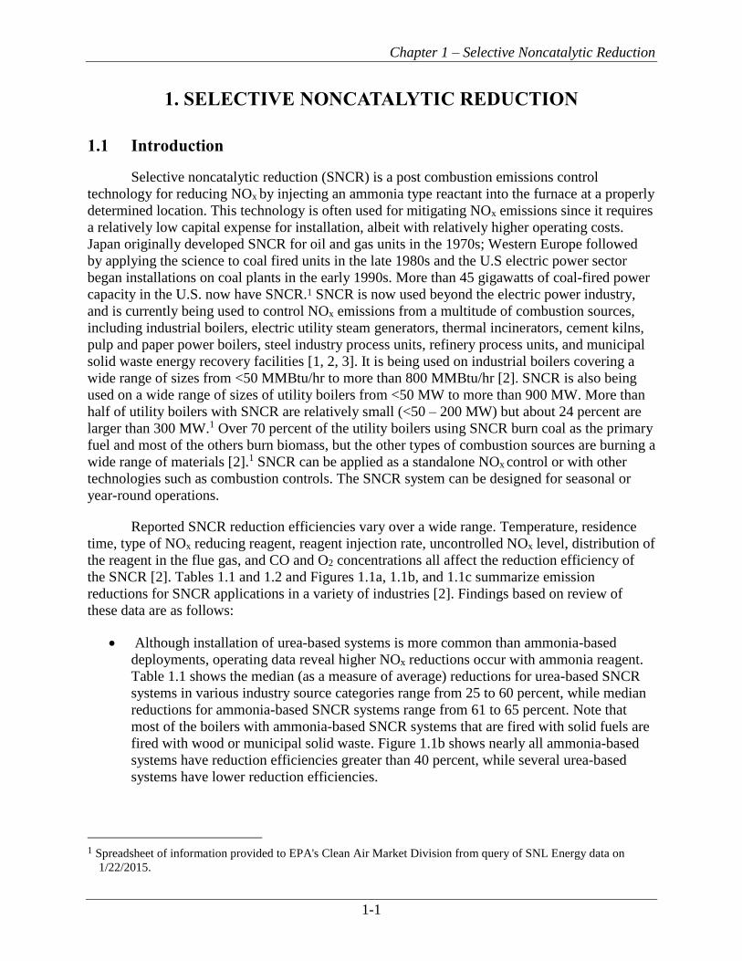
Based on applications in operation, capital costs for SNCR installations are generally low
due to the small amount of capital equipment required, and the cost per unit of output decreases
as the size of the source increases. For example, Figure 1.2 shows the installed capital cost of
SNCR technology for industrial boilers, on a $/MMBtu/hr basis, decreases as the size of the
boiler (and therefore the gross heat input in MMBtu/hr) increases. In addition, the installed
capital cost of SNCR applications ranged from $4-44/kWe (kilowatt) for power generation units
based on data for 2005-2007 [13]. The installed cost represents the cost of the capital equipment
plus the associated installation expenses, but does not include the operation, maintenance, or
reagent costs [1]. Table 1.3 contains a summary of average capital costs for SNCR applications
on various size units in several source categories.
Chapter 1 – Selective Noncatalytic Reduction
1-7
For cement kilns, the capital costs for SNCR systems range from $1.5 to $2 million and
are relatively consistent regardless of the type and production capacity of the kiln [9]. Because of
their lower production capacities, the capital costs per ton of clinker produced are generally
higher for long-wet and long-dry kilns than for preheater/precalciner kilns. One source reported
the capital costs for precalciner kilns to be $1 to $2 per ton of clinker [9]. As for other emission
units, SNCR operating costs for cement kilns vary by the desired level of uncontrolled NOx
emissions. The higher the uncontrolled NOx emissions and lower the desired NOx outlet
emissions, the greater the quantity of reagent used and hence, higher the operating cost. The NOx
emissions differ by kiln type, raw material composition, type of cement produced, fuel type, and
fuel injection location [8].
Most of the cost of using SNCR is operating expense. A typical breakdown of annual
costs for utilities is 25% for capital recovery and 75% for operating expense [2]. The primary
operating expense is for the NOx reduction reagent. Thus, the total annual costs vary directly
with the NOx reduction requirements. For industrial boilers, typical cost effectiveness values for
annual operation of SNCR are less than $3,000 per ton of NOx removed, and typical cost
effectiveness values for ozone season operation are less than $4,000 per ton of NOx removed
[1].3
Figure 1.2: Actual SNCR Installed Capital Costs on Industrial Sources Used with permission from ICAC [1]
3 The cited study reported cost-effectiveness values for more than 30 boilers. However, the study did not report the
year to which costs were normalized or the applicable year dollars for the individual values.

Chapter 1 – Selective Noncatalytic Reduction
1-8
Table 1.3: Summary of SNCR Cost Data
Source Category
Unit Size Fuel Type Capital Cost:
average (range)a $ Year Reference
Electric Generating Units
NA Coal NA ($10–$20/kW) [R] 2005$b [14]
NA NA NA ($5-$20/kW) 2008$b [2]
NA NA NA ($10-$30/kW) 2006$b [15]
NA NA NA ($4-44/KW) 2005-2007
[13]
Industrial-Commercial Boilers
>100 MMBtu/hr NA NA ($900–$2,500/MMBtu/hr or $9,000-$25,000/MW)
2006$ [16]
21–844 MMBtu/hr NA See Figure 1.2 2006$b [2, 17]
89–285 MMBtu/hr Wood NA ($0.924–$1.786 million) 2006$b [17]
>250 MMBtu/hr NA NA ($0.5-$1.0 million)
2000$b [18]
100–1,000 MMBtu/hr Coal NA ($2,600–$5,300/MMBtu/hr) [R]
1999$ [19]
100–1,000 MMBtu/hr Gas NA ($2,100–$4,200/MMBtu/hr) [R]
1999$ [19]
100–1,000 MMBtu/hr Oil NA ($2,000–$4,100/MMBtu/hr) [R]
1999$ [19]
350 MMBtu/hr Gas and paper sludge
NA ($0.775 million) [N]
[$0.50-0.75 million]e
1997$ [18]
155 MMBtu/hr Medium Density Fiberboard waste and wood waste
NA ($0.24 million) [N] 1996$ [18]
900 MMBtu/hr Wood NA ($1.1 million) 1999$b [18]
475 MMBtu/hr Wood NA ($0.70 million) 1999$b [18]
300 MMBtu/hr Wood NA ($0.60 million) 1999$b [18]
245 MMBtu/hr Wood NA ($0.39 million) 1999$b [18]
Portland Cement
1.095 million short tpy clinker
NA NA ($1.154 million or $1.05 per short ton clinker) [N]
2011$b [20]
1.09 million short tpy clinker
NA NA ($2.3 million or $2.1 per short ton clinker) [R]
2006$b [8, 21]
1.13 million short tpy clinker
NA NA ($2.3 million or $2.0 per short ton clinker) [R]
2006$b [8, 21]
2.16 million short tpy clinker
NA NA ($2.3 million or $1.1 per short ton clinker) [R]
2006$b [8, 21]
1.4 million short tpy clinker
NA NA ($1.153 million or $0.8 per short ton clinker)
2004$ [22]
NA NA NA ($1.4 million) [N] 2003$ [23]

Chapter 1 – Selective Noncatalytic Reduction
1-9
Source Category
Unit Size Fuel Type Capital Cost:
average (range)a $ Year Reference
<150 ton/hr (precalciner kiln)
NA NA ($0.40–$0.80 million)e 1999$b [18]
100 ton/hr (precalciner kiln)
NA NA ($0.08/ton clinker or $0.90 million)
1994$b [18]
0.3 million short tpy clinker (wet kiln)
NA NA ($1.4 million or $4.7 per short ton clinker) [R]
2006$b [8, 24]
0.320 million short tpy clinker (wet kiln)
NA NA ($1.2 million to $1.4 million or $3.8 to 4.4 per short ton clinker)
2006$b [8, 21]
Petroleum Refinery–Process Heater
350 MMBtu/hr Gas/refinery fuel gas or refinery oil
NA ($0.706–$2.59 million) [R]d
2004$c [25]
Petroleum Refinery–Boiler
650 MMBtu/hr Gas or refinery fuel gas
NA ($1.31–$4.80 million) [R]d
2004$c [25]
Pulp and Paper–Boilers
300,000 lb/hr Wood or wood/coal/oil
NA ($1.5 million) [R] 2004$b [14]
a Costs are for both new SNCR and retrofit SNCR, unless otherwise noted. [R] indicates costs are for retrofit only. [N] indicates costs are for new only, NA indicates the data are not available. b Year of reference. c Year analysis was conducted (assumed vendor contacts were made that year). d Costs are for SNCR only, that is part of combination control including LNB plus SNCR. e Cost does not include installation cost; installation would add 20–30% to the cost shown here.
1.2 Process Description
The basis of SNCR technology is a non-catalyzed chemical reaction utilizing an ammonia
based reagent (such as urea or ammonia) for reducing NOx into nitrogen (N2) and water (H2O) by
injecting this reagent into the post combustion gas stream at temperatures ranging from 1600-
2400°F (870–1320°C) [26]. The reagent can react with a number of flue gas components.
However, the NOx reduction reaction is favored over other chemical reaction processes for a
specific temperature range and in the presence of oxygen; therefore, it is considered a selective
chemical process.
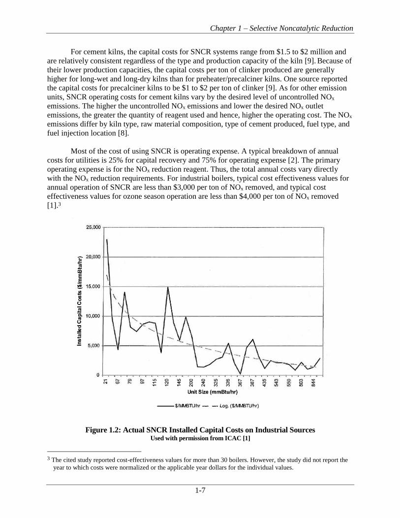
The conventional SNCR process occurs within the combustion unit, which acts as the
reaction chamber. Figure 1.3 shows a conventional SNCR process schematic for an electric
power boiler with injection nozzles mounted through the wall and penetrating the combustion
unit. The injection nozzles are located in the post-combustion area in the upper area of the
furnace near the convective passes. The injection causes mixing of the reagent and flue gas. The
heat of the boiler provides the energy for the reduction reaction. The NOx molecules are reduced
and the reacted flue gas then passes out of the boiler. More details on the SNCR process and
equipment are provided in the following sections.
Single- and multi-level injection systems for SNCR installations can be effective for NOx
reduction. Using different injector configurations can increase efficiency and reduce capital and
Chapter 1 – Selective Noncatalytic Reduction
1-10
operating costs. Several new approaches are currently being used in addition to conventional
SNCR installations, including SNCR Trim, Rich Reagent Injection, NOxSTAR, and ROTAMIX.
Figure 1.3: Boiler Gas Path Configuration
1.2.1 Reduction Chemistry
SNCR is a relatively simple chemical process. The process begins with an ammonia-
based reagent, ammonia (NH3) or urea [CO(NH2)2], being vaporized either before injection by a
vaporizer or after injection by the heat of the boiler. Within the appropriate temperature range,
the gas-phase urea or ammonia then decomposes into free radicals including NH3 and NH2. After
a series of reactions, the ammonia radicals come into contact with the NOx and reduce it to N2
and H2O.
Since NOx includes both NO and NO2, the overall reactions with urea and ammonia are
as follows:
2NO+2NH3+1/2O2→ 2N2+3H2O (1.1a)
2NO2+4NH3+O2→ 3N2+6H2O (1.1b)
Chapter 1 – Selective Noncatalytic Reduction
1-11
The urea reaction equations for NO and NO2 are:
2NO+CO(NH2)2+1/2O2→ 2N2+CO2+2H2O (1.2a)
2NO2+2CO(NH2)2+O2→3N2+2CO2+4H2O (1.2b)
Equations 1.1a and 1.2a are the predominant reactions because the 90 to 95% of NOx in
flue gas from combustion units is NO. The reaction occurs as a two-step process in which the
ammonia reacts with available hydroxyl radicals to form amine radicals and water:
NH3+OH→NH2+H2O
The amine radicals combine with nitrogen oxides to form nitrogen and water [8]:
NH2+NO→N2+H2O”
The primary byproduct formed in either ammonia- or urea-based SNCR systems is
nitrous oxide (N2O). N2O is an ozone depleter and greenhouse gas.4 Urea-based reduction
generates significantly more N2O than ammonia-based systems; up to 30% of the NOx can be
transformed into N2O [12, 27]. In one study, N2O emissions were measured at 0 to 7 μmol/mol in
ammonia-based SNCR, and as high as 27.8 μmol/mol in urea-based SNCR [28]. The amount of
N2O formed depends on the reagent feed rate and temperature, and increased N2O formation
correlates with increased NOx reductions [27, 29]. Proprietary additives are available for the
urea-based SNCR process to reduce the formation of N2O [12].
1.2.2 Reagents
Reagent costs currently account for a large portion of the annual operating expenses
associated with this technology, and this portion has been growing over time. Ammonia is
generally less expensive than urea since urea is derived from ammonia. However, the choice of
reagent is based not only on cost but also on physical properties and operational considerations.
The properties of urea and ammonia in aqueous solutions are shown in Table 1.4.
4 EPA issued a final rule on November 29, 2013 as part of a notice of data availability concerning the Mandatory
Greenhouse Gas Rule that indicates the global warming potential (GWP) of N2O is 298. The November 29, 2013
notice can be found in the Federal Register at http://www.gpo.gov/fdsys/pkg/FR-2013-11-29/pdf/2013-27996.pdf
.

Chapter 1 – Selective Noncatalytic Reduction
1-12
Table 1.4: Urea and Ammonia Reagent Properties [30]
Property Urea Solution Aqueous Ammonia
Chemical formula CO(NH2)2 NH3
Molecular Weight of reagent 60.06 17.03
Liquid or gas at normal air temperature
Liquid Liquid
Concentration of reagent normally supplied
50% by weight 19.0% by weight
Ratio of NH3 to solution 28.3% by weight of NH3 19.0% by weight of NH3
Density of solution @ 60°F 71 lb/ft3 58 lb/ft3 (56 lb/ft3 for 29.4%)
Vapor pressure @ 80°F <1 psia 14.8 psia [31]
Crystallization temperature 64°F −110°F
Flammability limits in air Non-flammable Lower explosion limit = 16% NH3 by volume Upper explosion limit = 25% NH3 by volume.
Threshold limit value (health effects)
Not specified 25 ppm
Odor Slight (ammonia-like) Pungent odor @ 5 ppm or more
Acceptable materials for storage Plastic, steel, or stainless steel (no copper or copper- based alloys or zinc/aluminum fittings)
Steel tank, capable of handling at least 25 psig pressure (no copper or copper-based alloys, etc.)
Ammonia can be supplied in either aqueous or anhydrous form. Anhydrous ammonia is a
gas at normal atmospheric temperature and must be transported and stored under pressure, which
presents safety issues and increases transportation cost [26]. Aqueous ammonia is generally
transported and stored at a concentration of 29.4% ammonia in water. At concentrations above
28%, storage of ammonia may require a permit; therefore, some applications of SNCR use
aqueous ammonia solutions of 19% [32]. For example, most U.S. cement plants use a solution of
19-20% aqueous ammonia reagent, while some cement plants in Europe use 25% ammonia
solutions [8, 33]. Decreasing the concentration, however, increases the required storage volume
and associated transportation costs. Ammonia may be injected either as a vapor or as an aqueous
solution. Providing sufficient ammonia vapor to the injectors requires a vaporizer, even though
the 29.4% solution has substantial vapor pressure at normal air temperatures. The injection
system equipment for vapor systems is more complicated and expensive than equipment for
aqueous systems (see Section 1.2.4, SNCR System).
Urea is generally stored in a 50% aqueous solution [2, 32]. At this concentration, the urea
solution must be heated and circulated in cold climates due to its low freezing point, 64°F
(18°C). Higher concentrations of urea solutions are available that decrease the storage volume
but require extensive heating to prevent freezing. Urea is injected into the boiler as an aqueous
solution and vaporized by the heat of the boiler. Urea can also be transported in pellet form,
which minimizes transportation requirements, or can be transported at a higher concentration,
which reduces the transportation cost due to the lower weight and volume of the solution.
However, to produce aqueous urea for use in the SNCR system, the urea must then be mixed
with water at the facility to dilute it to the 50% aqueous solution [26]. For urea pellets, this
dissolving, diluting, and mixing process is generally cost prohibitive except for remote sites,

Chapter 1 – Selective Noncatalytic Reduction
1-13
large facilities, or facilities where chemical mixing processes are already being performed, due to
the additional capital requirements associated with this process [26, 34]. Urea solutions become
more cost effective as the transported concentrations increase; the cost to transport a 70%
solution by rail to a third-party facility is 65% less than the cost to transport a 50% urea solution
and is 58% less than the cost to transport a 60% urea solution [26].
Urea-based systems have several advantages over ammonia-based systems. Urea is a
nontoxic, less volatile liquid that can be stored and handled more safely than ammonia. Urea
solution droplets can penetrate farther into the flue gas when injected into the boiler. This
enhances mixing with the flue gas, which is difficult on large boilers [32]. Because of these
advantages, urea is more commonly used than ammonia in large boiler applications of SNCR
systems.
Generally, anhydrous ammonia, which is typically used in conventional SNCR, is the
least costly reagent, with a nominal cost one-half that of 50% urea. A 29.4% aqueous ammonia
solution costs 150% more than anhydrous ammonia, and 70% urea costs 175% more than
anhydrous ammonia. However, the reagent characteristics associated with ammonia and urea
must also be taken into consideration. At any level of dilution, ammonia will flash evaporate
upon contact with flue gas; therefore, a physical distribution grid must be used, or in some
instances, an alternative high-energy lance injection system, such as the NOxSTAR or Rotamix,
must be used. These alternative SNCR technologies are discussed in Section 1.2.6 below. These
injection systems increase the overall capital cost, countering some of the cost savings associated
with dilution of anhydrous ammonia. Although urea is a more costly reagent, the vapor pressure
of urea is much lower than that of ammonia. Because urea is most efficiently introduced into the
system as a droplet, allowing for additional mixing with the flue gas and tailoring of the release
location, it is also a more flexible process than ammonia injection and is also typically more cost
efficient over time. In general, the use of 70% urea solution shipped by rail and diluted to 50%
onsite results in the lowest cost SNCR process for most applications, with a savings of 20%
compared to delivered cost of a 50% urea solution [26].
1.2.3 SNCR Performance Parameters
The design and operational factors affecting NOx reduction are:
▪ Reaction temperature (sp.: furnace temp)
▪ Residence time (reagent injection location)
▪ Degree of mixing
▪ Uncontrolled NOx concentration (starting NOx)
▪ Ratio of injected reagent to uncontrolled NOx (amount of reagent injected); and
▪ Ammonia slip (which is strongly influenced by the ratio of injected reagent to uncontrolled
NOx)
Figures 1.4 through 1.8 in this section present graphical representations of the effect of
these factors on SNCR reductions. The plots are intended to illustrate trends and relative effects
of the factors as discussed in the text, but they are not based on test data.
Chapter 1 – Selective Noncatalytic Reduction
1-14
Temperature
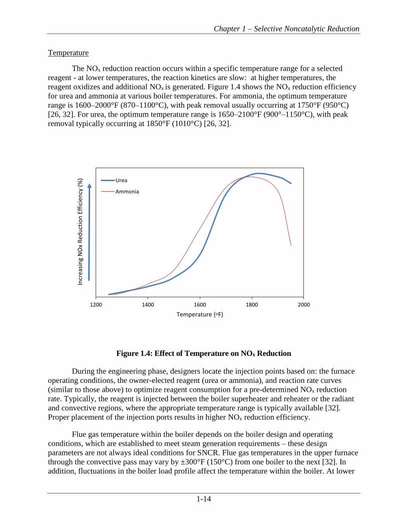
The NOx reduction reaction occurs within a specific temperature range for a selected
reagent - at lower temperatures, the reaction kinetics are slow: at higher temperatures, the
reagent oxidizes and additional NOx is generated. Figure 1.4 shows the NOx reduction efficiency
for urea and ammonia at various boiler temperatures. For ammonia, the optimum temperature
range is 1600–2000°F (870–1100°C), with peak removal usually occurring at 1750°F (950°C)
[26, 32]. For urea, the optimum temperature range is 1650–2100°F (900°–1150°C), with peak
removal typically occurring at 1850°F (1010°C) [26, 32].
Figure 1.4: Effect of Temperature on NOx Reduction
During the engineering phase, designers locate the injection points based on: the furnace
operating conditions, the owner-elected reagent (urea or ammonia), and reaction rate curves
(similar to those above) to optimize reagent consumption for a pre-determined NOx reduction
rate. Typically, the reagent is injected between the boiler superheater and reheater or the radiant
and convective regions, where the appropriate temperature range is typically available [32].
Proper placement of the injection ports results in higher NOx reduction efficiency.
Flue gas temperature within the boiler depends on the boiler design and operating
conditions, which are established to meet steam generation requirements – these design
parameters are not always ideal conditions for SNCR. Flue gas temperatures in the upper furnace
through the convective pass may vary by ±300°F (150°C) from one boiler to the next [32]. In
addition, fluctuations in the boiler load profile affect the temperature within the boiler. At lower
1200 1400 1600 1800 2000
Incr
easi
ng
NO
x R
edu
ctio
n E
ffic
ien
cy (
%)
Temperature (oF)
Urea
Ammonia

Chapter 1 – Selective Noncatalytic Reduction
1-15
load profiles, the temperature within the boiler is lower. Variations in the flue gas temperature
make the design and operation of an SNCR system more difficult.
Combustion units operated at low load or with different fuels may result in changes in the
temperature profile in the combustion unit. In some cases, temperatures may be below the
optimum required for achieving NOx reductions. To address this concern, some SNCR systems
are designed with multi-level reagent injection locations, temperature sensors, and automatic
controls to allow switching between injection ports. These systems ensure that reagent is always
injected at the location with the optimum temperature for NOx reduction.
Residence Time
By definition, residence time is the amount of time the reactants are present within a
chemical reactor. The longer the residence time, the greater conversion achieved. The upper area
of the furnace is the reaction area for the SNCR process with flue gas velocity determining
residence time within this fixed area; however, boiler design establishes flue gas velocity.
Increasing the residence time available for mass transfer and chemical reactions generally
increases the NOx removal. In addition, as the temperature window for the reaction is lowered,
greater residence time is required to achieve the same NOx reduction level. Residence time can
vary from 0.001 to 10 seconds [32]. However, the gain in performance for residence times
greater than 0.5 seconds is generally minimal, and performance degradation is observed for
residence times less than 0.2 seconds [12, 26]. Figure 1.5 shows the effect of residence time and
temperature on NOx reduction.
The amount of residence time depends on the dimensions of the boiler gas path and the
volumetric flow rate. These design parameters are optimized for steam generation and prevent
watertube erosion. Consequently, the residence time in the boiler is not always ideal for the
SNCR process.
Figure 1.5: Effect of Residence Time on NOx Reduction
1400 1600 1800 2000 2200Incr
easi
ng
NO
x R
edu
ctio
n E
ffic
ien
cy (
%)
Temperature (oF)
500ms

Chapter 1 – Selective Noncatalytic Reduction
1-16
Degree of Mixing
For optimal reaction rates and decreased reagent consumption, the reagent is properly
mixed with the flue gas via a multi-point injection grid situated within the furnace. The mixing
requirements are unit specific and depend on the air flow profiles through the furnace [32].
Mixing is performed by the injection system. The injectors atomize the reagent and control the
spray angle, velocity, and direction of the injected reagent. These systems are boiler and reagent
specific. Numeric modeling of the flue gas and reagent flow optimizes the design of the injection
system (see Section 1.2.5, Other Considerations).
To assist in dispersion of aqueous urea, the reagent is atomized into droplets by specially
designed nozzles that optimize the droplet size and distribution. Evaporation time and trajectory
are a function of the diameter of the droplet. Larger droplets have more momentum and penetrate
farther into the flue gas stream; however, they require a longer time to volatilize, increasing the
required residence time [32].
Inadequate mixing results in insufficient NOx reduction. Mixing patterns can be improved
by several methods:
▪ Increase the energy imparted to the droplets;
▪ Increase the number of injectors;
▪ Increase the number of injection zones; and
▪ Modify the atomizer nozzle design to improve the solution droplet size, distribution, spray
angle, and direction.
Uncontrolled NOx
The concentration of the reactants also affects the reaction rate of the NOx reduction
process. The reaction kinetics decrease as the concentration of reactants decreases. This is due to
thermodynamic considerations that limit the reduction process at low NOx concentrations [32].
For lower NOx inlet concentrations, the optimum temperature for the reaction is lower; hence,
the percent NOx reduction is lower. Figure 1.6 shows the NOx reduction efficiency as a function
of temperature for several uncontrolled NOx levels.

Chapter 1 – Selective Noncatalytic Reduction
1-17
Figure 1.6: Effect of Uncontrolled NOx Level on NOx Reduction Efficiency
Normalized Stoichiometric Ratio
The normalized stoichiometric ratio (NSR) defines the amount of reagent needed to
achieve the targeted NOx reduction. Theoretically, based on reaction equations 1.1(a) and (b) and
1.2(a) and (b), two moles of NO can be removed with one mole of urea or two moles of
ammonia and one mole of NO2 requires one mole of urea and two moles of ammonia. Since NOx
is mostly comprised of NO (approximately 95%), the theoretical NSR for NOx is close to one
mole of ammonia per mole of NOx and 0.5 moles of urea per mole of NOx. In practice, more than
the theoretical amount of reagent needs to be injected into the boiler flue gas to obtain a specific
level of NOx reduction. This is due to the complexity of the actual chemical reactions involving
NOx and injected reagent and mixing limitations between reagent and flue gas (rate kinetics).
Typical NSR values are between 0.5 and 3 moles of ammonia per mole of NOx [12]. Because
capital and operating costs depend on the quantity of reagent consumed, determining the
appropriate NSR is critical. The factors that influence the value of NSR include the following:
▪ Percent NOx reduction;
▪ Uncontrolled NOx concentration in the flue gases;
▪ Temperature and residence time available for the NOx reduction reactions;
▪ Extent of mixing achievable in the boiler;
▪ Allowable ammonia slip; and
▪ Rates of competing chemical reactions.
1500 1600 1700 1800 1900 2000 2100
Incr
easi
ng
NO
x R
edu
ctio
n E
ffic
ien
cy
Temperature (oF)
30 ppm
70 ppm
200 ppm

Chapter 1 – Selective Noncatalytic Reduction
1-18
Section 1.3, Design Parameters, provides further discussion of these influences and a
method for estimating the NSR.
Figure 1.7 shows the NOx reduction as a function of the NSR. Note that as the NSR
increases, the NOx reduction increases. However, as the NSR increases, the increment of NOx
reduction decreases exponentially. Rate kinetics limit the possible NOx reduction to much less
than the theoretical value. Increasing the quantity of reagent does not significantly increase the
NOx reduction for NSR values over 2.0.
Figure 1.7: Effect of NSR on NOx Reduction
Ammonia Slip
Ammonia slip results from excess reagent injection to overcome inherent natural system
limitations to obtain the desired level of NOx reduction. Although the level of ammonia slip will
differ from one unit to the next based on the limitations inherent to each system, for any
individual SNCR, the NOx reduction and ammonia slip are established by the reagent injection
rate – an operational setting that can be adjusted based on the desired NOx reduction and allowed
ammonia slip. Typical NSR values require significantly more reagent to be injected in practice
than is required by the theoretical stoichiometric ratio. Figure 1.8 shows an example of the NOx
reduction efficiency that can be achieved for an uncontrolled NOx level of 120 parts per million
(ppm) and various ammonia slip levels.
0 0.5 1 1.5 2 2.5 3
Incr
easi
ng
NO
x R
edu
ctio
n E
ffic
ian
cy (
%)
NSR

Chapter 1 – Selective Noncatalytic Reduction
1-19
Figure 1.8: NOx Reduction for Various Ammonia Slip Levels
Ammonia in the flue gas stream has several negative impacts. As shown in Table 1.4,
ammonia has a detectable odor at levels of 5 ppm or greater and poses a health concern at levels
of 25 ppm or greater. It can cause a stack plume visibility problem by the formation of
ammonium chlorides, which occur when burning fuels containing chlorine compounds.
Furthermore, ammonium bisulfate and ammonium sulfate form when burning sulfur-containing
fuels or when cement kiln raw materials contain pyritic sulfur. Ammonia-sulfur salts can plug,
foul, and corrode downstream equipment such as air heaters, ducts, and fans. Lastly, the ability
to sell the fly ash as a secondary product is affected by its ammonia concentration. Ammonia slip
impacts are discussed further later in this chapter in Section 1.2.5, Other Considerations.
Limits on acceptable ammonia slip, imposed by either regulatory limits or design
requirements, place constraints on SNCR performance. For example, utilities typically have
ammonia slip limits of 5 to 10 ppmv. Injection of urea at higher NSR values can improve NOx
reduction but may also increase ammonia slip. The sulfur content of the fuel can also restrict the
amount of ammonia injected due to the formation of ammonium sulfate and bisulfate salts that
can deposit on air heater surfaces and cause plugging and reduced efficiency. Combustion units
that burn fuels with high sulfur contents are generally limited to ammonia slip levels of 5 ppm to
help minimize the formation of ammonium sulfate and bisulfate. In addition, variation in the
temperature profile of the boiler during operations can increase ammonia slip. In general, current
SNCR systems control ammonia slip between 2 and 10 ppm [35]. Ammonia slip monitoring
instruments are commercially available and are in place and operating at a number of coal-fired
units. Facilities typically install ammonia slip monitors between the SNCR and the air heater and
may measure at one or several points. These systems monitor ammonia slip and help the unit
maintain slip levels of 2–3 ppmv or less. The cost to purchase one ammonia slip monitoring
instrument is estimated to be $40,000 for a single measurement point and up to $70,000 for three
0 5 10 15 20
Incr
easi
ng
NO
x R
edu
ctio
n E
ffic
ien
cy (
%)
Ammonia Slip (ppm)

Chapter 1 – Selective Noncatalytic Reduction
1-20
measurement points [36]. Ammonia slip can also be controlled by establishing a feedback
control loop to adjust the reagent injection feed rate according to the ammonia slip level
measured by the monitor [26]. Another method of quantifying ammonia slip is to determine the
ammonia concentration in collected fly ash.
Raw materials at some cement kilns contain constituents that when heated release
ammonia to the kiln gas stream. Therefore, for cement kilns it is important to understand the rate
of raw material derived ammonia emissions before designing SNCR control systems and
establishing ammonia slip limits.
Carbon Monoxide
High CO concentrations have been shown to lower the optimum reaction temperature,
widen the temperature window, and reduce the NOx control efficiency [2, 37, 38, 39, and 40].
Researchers believe this occurs because CO competes for the hydroxyl free radicals that are
required for NO to be converted to N2. Researchers also note that CO effects may be
compounded in systems using urea because CO is generated during urea dissociation. Since
oxygen is needed to generate the hydroxyl free radicals, flue gas with high CO concentrations
and low O2 concentrations will reduce the NOx control efficiency. However, some studies have
shown that increasing the O2 concentration above 2.4% can promote NOx reduction by providing
sufficient hydroxyl free radicals for the NO to N2 reaction. Higher oxygen levels also promote
the conversion of CO to CO2, which is believed to create localized areas of high temperature due
to the release of heat from CO2 formation [4].
1.2.4 SNCR System
Two basic designs for the application of SNCR were developed in the 1970s and early
1980s [41, 42]. The first was an ammonia-based system known as Thermal DeNOx that was
developed and patented by Exxon Research and Engineering Company in 1975. The second was
a urea-based system known as NOx OUT that was developed and patented by the Electric Power
Research Institute (EPRI) in 1980 and subsequently licensed to Fuel Tech [43, 44]. Since that
time, there have been a number of variations and improvements to the urea SNCR process,
which are noted in Section 1.2.
An SNCR system has four basic steps to accomplish:
▪ Receiving and storing the reagent;
▪ Diluting, metering, and mixing the reagent;
▪ Injecting diluted reagent at appropriate locations in the boiler; and
▪ Mixing the reagent with flue gas.
These steps are common to both urea and ammonia SNCR applications; however, the
design and equipment specifications for SNCR systems may differ. For example, SNCR systems
using anhydrous ammonia inject the reagent as a vapor, while systems using aqueous ammonia
solutions and urea typically inject the reagent as an aqueous solution. Urea is typically used in
large boiler applications of SNCR because it is safer to store, has better dispersion properties,
and can use droplet evaporation for effective injection at the higher temperatures found in utility

Chapter 1 – Selective Noncatalytic Reduction
1-21
furnaces. However, ammonia-based systems are used on industrial boilers, some fluidized-bed
utility boilers, and cement kilns.
For long wet and dry cement kilns the SNCR will require either the installation of a
rotary valve at the end of the rotary kiln or the Cadence™ manifold system because the reagent
must be injected into the rotary kiln. These are not required for SNCR systems installed on
preheater/precalciner cement kilns because the injection ports can be installed in the combustion
zone in the calciner, the oxidation zone of the upper air inlet before the deflection chamber, or in
the area after the mixing chamber before the inlet to the bottom cyclone [8].
A discussion of the SNCR equipment is given below. Figure 1.9 presents a simplified
system flow schematic and Table 1.5 lists the equipment requirements for urea-based SNCR.
Urea-based systems typically employ a modular design to allow for boiler-specific design
requirements while minimizing capital costs. Modular shop assembly of pumps, valves, internal
piping, instruments, and controls reduces field installation time and related costs while providing
flexibility for future expansion [32]. The components are assembled into functional units and
mounted on stainless steel skid modules. These modules can then be transported to the site and
installed directly. The skid modules shown in Figure 1.9 will be discussed further in the next
sections.
It is typical for large industrial sources employing urea-based SNCR systems to store
10,000–20,000 gallons per tank to maintain sufficient volume for 1–3 weeks of SNCR
operations. A closed top, flat bottom, vertical tank is used for urea storage. These tanks are
usually constructed of fiber-reinforced polyester and have a corrosion barrier coating on the
inside made of premium-grade vinyl ester resin. The tanks are equipped with level and
temperature indicators; a manway, vent, and access ladder; and other appurtenances. The
applicability of heat tracing, insulation, and seismic design criteria are determined based on site-
specific conditions. The tank should be mounted on a concrete pad and surrounded by a spill
containment structure such as a dike.

Chapter 1 – Selective Noncatalytic Reduction
1-22
Figure 1.9: Urea SNCR Process Flow Diagram [32]
Table 1.5: Urea-Based SNCR System Equipment
Item Description/Size
Urea unloading skid Centrifugal pumps with hoses to connect to rail tank car or truck
Urea storage tanks Vertical, insulated fiberglass reinforced plastic (1 or more tanks) (vinyl ester resin) tank, atmospheric pressure design, and equipped with a vent, caged ladder, manway, and heating pads
Circulation module Skid-mounted circulation module consisting of
• Circulation pumps,
• Electric heaters,
• Insulated/heat traced piping,
• Isolation valves for pumps and heaters, and
• Instrumentation for flow, pressure, temperature, and a control panel

Chapter 1 – Selective Noncatalytic Reduction
1-23
Item Description/Size
Injection zone metering (IZM) modules (1 to 5 modules)
Skid mounted metering modules consisting of
• Metering pumps, hydraulic diaphragm type equipped with a variable speed motor drive,
• Water booster pumps, turbine type,
• Insulated/heat traced piping,
• Isolation and control valves for pumps,
• Instrumentation for flow, pressure, temperature, and a control panel
Air compressor Distribution modules (1 to 5 modules)
Rotary type (including long-wet and -dry cement kilns) Urea solution distribution module consisting of,
• Valved connections for urea and atomizing air (e.g., CadenceTM system),
• Isolation valve and a pressure control valve for the air/urea supply to each injector,
• Pressure indicator for air/urea supply to each injector,
• Flow indicator for urea supply to each injector
Injectors (4 to 12 per distribution module)
Wall-type: Dual-fluid type wall injector, with modules, furnace wall panels, and hoses for air and urea supplies
Lance-type: Dual-fluid type lance injector, with furnace wall panels, and hoses for air and urea supplies
Piping Between urea unloading skid and urea tank; urea tank and circulation module; and circulation module and IZM modules(s). Insulate/heat traced piping, stainless steel
Piping Between IZM module(s) and distribution modules. Insulated/heat traced tubing, stainless steel
Tubing Between distribution modules and injectors. Insulated/heat traced tubing, stainless steel
Dilution water piping Insulated/heat traced piping, carbon steel, with isolation and pressure reducing valves
Miscellaneous piping Piping/tubing and valves for flushing water, atomizing air, and control air
Piping supports Structural support steel, including a pipe bridge, for supporting all piping and oxygen in the flue gas and providing a feedback signal for urea injection control
Economizer outlet emission monitors
Monitors NOx and O2 in the flue gas and provides a feedback signal for urea injection control
Instrumentation and controls Instrumentation and standalone, microprocessor-based controls for the SNCR system with feedback from the plant controls for the unit load, NOx emissions, etc.
Enclosures
Pre-engineered, heated and ventilated enclosure for the circulation and metering skids
Foundations Foundations and containment walls for the tank and equipment skids, enclosure, and piping support steel, as required
Platforms/stairways Platform/stairway modifications and additions for access to injectors
Asbestos removal Asbestos removal and reinsulation for a retrofit installation
Circulation Module
The circulation module maintains continuous circulation of the stored urea and supplies
high-flow, high-pressure urea to the injection system. The circulation module pumps the urea
from the storage tank to the components on the module. The urea solution is filtered to avoid
clogging of the injectors and heated to prevent the solution from freezing. The urea is then

Chapter 1 – Selective Noncatalytic Reduction
1-24
returned to the tank or sent to the injection system. The module also provides a local/remote
control and monitoring station for the storage tank and circulation system. This module contains
multistage stainless-steel centrifugal pumps, inline duplex strainers, electric heaters, and
instrumentation and controls for reagent pressure, flow, temperature, and quantity [32].
Diluting, Metering, and Mixing of the Reagent
Dilution Water Pressure Control Module
The dilution water pressure control module provides filtered plant water at the proper
pressure for reagent dilution. The plant water is filtered to less than 50 milligrams per liter
(mg/L) of suspended solids and low dissolved solids. The dilution water pressure module
typically consists of two full-flow multistage stainless-steel centrifugal pumps, an inline duplex
strainer, pressure control valves, and the required pressure/flow instrumentation. Through the use
of backpressure controllers and multistage pumps, this system maintains a constant supply of
dilution water, at the design pressure, in response to the changing SNCR process demand
signals [32]. The 50% solution from storage is diluted for injection, typically to either 5% or
10% [11, 32].
Injection Zone Metering Module
The injection zone metering (IZM) module meters and controls the reagent concentration
and flow to each zone of injection in the boiler. The aqueous urea generally requires dilution
before injection to achieve the correct NSR between the reagent and flue gas NOx. The reagent is
diluted using filtered plant water from the dilution water pressure module. Each IZM module
includes a chemical metering pump, a water pump, an inline static mixer, a local control panel,
zone isolation valves, and magnetic flow meters and control valves for chemicals and water. The
module design generally incorporates independent chemical flow and zone pressure valves,
which respond to signals from the control systems, the master control module, and the local
programmable logic controller. Through the control system, the module adjusts solution flow
rates and activates or deactivates injection zones in response to changes in outlet NOx
concentration, boiler load, or fuel quality. Urea-based SNCR systems typically employ one to
five IZM modules, depending on the boiler size and configuration, the uncontrolled NOx
concentration, and the desired NOx removal efficiency. Several IZM modules can be combined
onto one skid-mounted system [32].
Injecting of Diluted Reagent at Appropriate Locations in the Boiler
Reagent Distribution Module
The mixed and diluted urea solution is transported from the IZM to the distribution
modules, which are typically located adjacent the boiler. The distribution modules control the
flow of the solution to each injector. Each of the distribution modules consists of flow meters,
balancing valves, and regulators connected to an automatic control system. The control system
accurately controls and displays the reagent and atomizing air or steam flow to each injector. The
modules also include manual ball valves, gauges, and stainless-steel tubing to adequately control

Chapter 1 – Selective Noncatalytic Reduction
1-25
the urea injection process. One distribution module for each IZM module provides reagent to
multiple injectors [32].
Injection Locations
The urea solution flows from a given distribution module to a set of injectors. For large
boiler applications, multiple injectors are located within several different zones of the boiler and
can be operated independently or in groups (sub-zones) via the IZM. Controlling the amount and
location of reagent injection gives the system flexibility to respond to variation in the boiler
operating conditions and to maintain ammonia slip levels.
The number and location of the zones is determined by the temperature and flow patterns
of the boiler. The locations are optimized using numeric modeling of flow and chemical
reactions (see Section 1.2.5, Other Considerations). Typical designs employ 1–5 injection zones
with 4–12 injectors per zone [32]. Injectors are located in open areas of the boiler, such as the
region between the superheater and reheater sections. Figure 1.3 illustrates this configuration.
For SNCR retrofit of existing boilers, optimal locations for injectors may be occupied by boiler
equipment such as the watertubes. Removal or relocation of this equipment increases the
installation costs. Installation in suboptimal boiler areas decreases the NOx reduction efficiency
that can be achieved by the system while maintaining the required ammonia slip level.
Pilot testing using several reagent injection locations may be used to establish the
optimum location(s) for reagent injection. Pilot testing has been used in preheater and
precalciner cement kilns [8].
Mixing of the Reagent with Flue Gas and Reduction of NOx
Injectors
The injectors assist in dispersion and mixing of the reagent with the flue gas. There are
two types of injectors, wall and lance:
▪ Wall injectors are attached to the inner wall of the boiler at specified locations. There is
generally one nozzle for each injector location. They may be used in small or large
combustion units. Smaller boilers and urea-based systems in which short-range injection is
sufficient to mix the reagent with the flue gas may be equipped only with wall injectors. In
larger boilers, wall injectors are often used in combination with lance injectors to improve
reagent coverage near the walls. They have a longer operating life than lance injectors
because they are not directly exposed to hot flue gas. Wall injectors may use air or
mechanical atomization prior to reagent injection.
▪ Lance injectors consist of a small pipe that protrudes from the boiler wall into the flue gas
pathway. Nozzles are located along the pipe directly in the flue gas pathway. Lance
injectors are used for ammonia gas systems and in large boilers where mixing of the flue
gas and reagent is more difficult. In some designs, the lance extends across the entire
width of the boiler pass. Lance injectors can be single- or multi-nozzle designs.

Chapter 1 – Selective Noncatalytic Reduction
1-26
Multinozzle lances are a more complicated design; therefore, they are more expensive than
single-nozzle lance or wall injectors [32].
SNCR systems may employ one or both types of injectors.
Injectors are subject to high temperatures and to flue gas impingement, which cause
erosion, corrosion, and structural integrity degradation. Therefore, injectors are generally
constructed of stainless steel and designed to be replaceable. In addition, injectors are often
cooled with air, steam, or water. Lance injectors and some wall injectors are also designed to be
retractable when not in use. This minimizes their exposure to the hot flue gas when the SNCR
system is not being operated because of seasonal operations, boiler startup or shutdown, or other
operational reasons.
The reagent is injected under pressure and atomized by specially designed nozzle tips to
create droplets of the optimum size and distribution. The spray angle and velocity of the injection
control the trajectory of the reagent. Urea systems often inject a carrier fluid, typically air or
steam, along with the urea through a dual-fluid atomizer nozzle. The reagent can be injected with
a low- or high-energy system. A low-energy system uses little or no pressurized air while a high-
energy system uses large amounts of compressed air or steam to inject and vigorously mix the
solution with the flue gas. Lance injectors in large boilers typically use high-energy systems.
High-energy systems are more expensive to build and operate because they require a larger
compressor and a more robust injection system and consume more electric power.
The reagent injection systems used for anhydrous ammonia-based systems are generally
more complicated and expensive than those used in aqueous ammonia- and urea-based systems
[32]. These systems inject gas-phase ammonia rather than an aqueous solution. For this reason,
anhydrous ammonia-based systems often use high-energy lance systems with multiple injectors.
The lances are placed in a grid formation across the width and height of the boiler passes.
1.2.5 Other Considerations
Retrofit
The difficulty of SNCR retrofit on existing large coal-fired boilers is considered to be
minimal. The primary concern is adequate wall space within the boiler for installation of
injectors. The injectors are installed in the upper regions of the boiler, the boiler radiant cavity,
and the convective cavity. Existing watertubes and asbestos may need to be moved or removed
from the boiler housing. In addition, adequate space adjacent to the boiler must be available for
the distribution system equipment and for performing maintenance. This may require
modification or relocation of other boiler equipment, such as ductwork. The methodology
presented in section 1.4 estimates SNCR capital costs that model actual costs for typical SNCR
retrofits at existing boilers. The estimated costs on a $/kW basis increase sharply for small
boilers (<50 MW) due to both economies of scale and to account for the more difficult
installation conditions that are often encountered for the small boilers. As such, estimates based
on this methodology typically should not include an additional retrofit factor for existing boilers.
Little data are available regarding the cost of new installations versus retrofits. One study
suggested retrofit installation of the SNCR system generally calls for additional expenditures in

Chapter 1 – Selective Noncatalytic Reduction
1-27
the range of 10–30% of the SNCR system cost [12], a minimal increase. Based on this study,
costs for installation at new facilities may be 9 to 23 percent lower than the costs for retrofits at
existing sources.
Ammonium Sulfate Deposition and Fly Ash Considerations
Sulfur trioxide (SO3) forms during the combustion of fuels that contain sulfur. It reacts
with ammonia in the flue gas downstream of the boiler (ammonia slip) to form ammonium
bisulfate and ammonium sulfate. The amount formed depends on the sulfur content of the fuel
and the amount of ammonia slip. Ammonia-sulfur salts can plug, foul, and corrode downstream
equipment such as the air heater, ducts, and fans. Depending on the rate of ammonia-sulfur salt
deposition on downstream equipment, more frequent acid washing of this equipment may be
warranted. Increased acid washing generates additional wastewater that must be disposed of or
treated by the plant. Ammonia slip limits are generally imposed as part of the design
requirements to avoid impacts on downstream equipment.
Ammonia sulfates also deposit on the fly ash that is collected by particulate removal
equipment. The ammonia sulfates are stable until introduced into an aqueous environment with
an elevated pH level. Under these conditions, ammonia gas can be released into the atmosphere.
This results in an odor problem or, in extreme instances, a health and safety concern. Plants that
burn alkali coal or mix the fly ash with alkali materials can have fly ash with high pH. In general,
fly ash is either disposed of as waste or sold as a byproduct for use in processes such as concrete
admixture. Ammonia content in the fly ash greater than 5 ppm can result in off-gassing, which
would impact the ability to sell the ash as a byproduct and the storage and disposal of the ash by
landfill [12, 45].
Ammonia slip mitigation (ASM) technology exists to treat fly ash that is contaminated
with ammonia. The technology consists of blending a chemical oxidizer such as calcium
hypochlorite with the dry fly ash. When combined with water the calcium hypochlorite reacts
with some of the ammonia in solution to form chloramines. Overtreatment, however, can result
in the release of chlorine gas when the fly ash is mixed with water. Treatment for typical
operating conditions has reportedly reduced ammonia levels by roughly 30 to 50 percent. The
total annual cost for one electricity generating unit was estimated to be $5.61 per ton of ash
treated [45].
Computational Fluid Dynamics (CFD) and Chemical Kinetic Modeling
Each boiler unit has a unique temperature and flow gradient with areas of high flow and
stagnation. In addition, temperature and flow profiles vary according to the load capacity under
which the boiler is operating. A mathematical model is developed to describe this stratification
and variation of important species such as NOx and SO3 in the flow stream. To develop the
model, the flue gas temperature and velocity within the boiler are measured at many locations.
These measurements are used in a CFD model for the convective passes of the boiler. The model
predicts the temperature and gas flow within the boiler for various operating conditions and
injection scenarios.
The residence times and temperatures predicted by the CFD model are input into a
chemical kinetic model, which defines the chemical reactions associated with the SNCR process

Chapter 1 – Selective Noncatalytic Reduction
1-28
in the boiler. Analysis of the fuel and flue gas constituents is required to develop this model. The
model predicts the reactions and rates of reactions within the boiler in order to estimate the NOx
reduction along the flue gas pathway.
Modeling such as this optimizes the SNCR design for the boiler of concern to obtain the
maximum NOx reduction within acceptable ammonia slip limits. It determines design parameters
such as the NSR, injector locations, and optimum droplet size and distribution. In general, SNCR
vendors obtain the required measurements and develop the models. The cost of model
development is generally included in the purchased equipment cost for SNCR [32].
Additives/Enhancers
Additives to the reagents are called enhancers and can be used to lower the temperature range at
which the NOx reduction reaction occurs. During low-load operation, the location of the
optimum temperature region shifts upstream within the boiler. This shift requires the injection
point of the reagent to be moved upstream. The use of an enhancer reduces the need for
additional injection locations, which are required to compensate for variable load operation.
Fewer injection locations decrease capital costs and the need for modifications to the boiler. In
addition, the larger temperature range available with enhancers increases the available residence
time for the reduction reaction, further reducing NOx emissions. Additional reagent is injected
with the enhancer to maintain the same NOx reduction efficiency because some of the reagent
reacts with the enhancer as opposed to the NOx. This can increase the reagent usage by up to
10%. In addition, enhancers can result in increased levels of CO and N2O in the stack effluent.
Enhancers require additional storage, distribution, and control system equipment. Enhancer
formulations are generally proprietary [12].
Since the early 1990s, the co-injection of hydrogen with ammonia has been known to
lower the effective temperature window to about 700 oC (1300 oF) [46].5 There are also several
studies evaluating the effect of other additives, including carbon monoxide, glycerol, methyl
acetate, phenol, succinic acid, propionaldehyde, diethyl ether, hydrogen peroxide, and several
alcohols (e.g., methanol, ethanol, toluene, ethylene glycol, and phenol). Studies have
demonstrated that additives such as ammonium carbonate, ethanol, methanol, toluene, phenol,
and ethylene glycol can decrease the optimum reaction temperature by up to 180oC. However,
many these additives have also been shown to reduce NOx reduction efficiency [40, 47]. One
study found that urea mixed with ethylene glycol or glycerol can widen the temperature range
from the low 800oC to high 1200oC with a NOx removal efficiency of greater than 45% [47].
However, there are no known commercial applications of these additives.
Energy Consumption
An SNCR process reduces the thermal efficiency of a boiler. The reduction reaction uses
thermal energy from the boiler, which decreases the energy available for power or heat
generation. As a result, additional energy is required for the boiler to maintain the same steam
output. Pretreatment and injection equipment, pumps, compressors, and control systems, also
require electricity. This increased usage of fuel and electricity increases the annual costs required
5 See http://www.hamonusa.com/hamonresearchcottrell/products/nox.

Chapter 1 – Selective Noncatalytic Reduction
1-29
to operate the boiler [29]. Section 1.4.2, Total Annual Costs, presents a method for estimating the
additional fuel and electricity usage.
1.2.6 New SNCR Approaches
Several advances to conventional SNCR technology have been made. The alternative
approaches include systems such as SNCR Trim, Rich Reagent Injection (RRI), NOxSTAR and
ROTAMIX. These systems use different injector configurations to improve efficiency and
reduce costs. The costs presented in this discussion are from 2004 to 2006 and thus should not be
considered current. However, it is expected that the trends or ranking have not changed.
SNCR Trim
The SNCR Trim technology is a simple, low-cost, low-energy single-level injection
system with injectors located approximately five feet apart along the front wall of the upper
furnace. By using upper furnace injection, the droplet trajectory can be optimized for penetration
into the bulk turbulent mixing in the furnace. SNCR Trim has been applied to more than 21 coal-
fired utility boilers and has been demonstrated for utility boilers ranging from 35 to 720 MW.
Typical NOx reductions of 25–35% are achieved. Capital costs for SNCR Trim installations are
typically projected to be half what would be incurred for a conventional SNCR in the same
application, approximately $5-10/kW for a single level of injectors [26].
Rich reagent injection
RRI involves the injection of urea or ammonia into a high-temperature, fuel-rich
environment with a residence time of 0.5–1 seconds. The efficiency of RRI depends on the
extent of overall mixing and is typically in the range of 30-40% NOx reduction. Ammonia slip
with the RRI process is minimal because any unreacted urea or ammonia is oxidized to nitrogen
oxide (NO) in the upper furnace. RRI has been demonstrated to achieve 30% NOx reductions in
two existing cyclone-fired boilers with overfire air. For a 500-MW cyclone boiler with a single
level of injectors, the capital cost for RRI alone is approximately $8-12/kW. RRI can be
combined with SNCR Trim to achieve an overall NOx reduction efficiency of 55% when
operated during ozone season, for an additional capital cost of $4/kW and an overall cost
effectiveness of $1,447 per ton of NOx removed [26].
NOxSTAR
NOxSTAR uses an injection grid to provide NOx control by injecting ammonia and a
hydrocarbon into a utility boiler within the flue gas path at a temperature in the range of 1800–
2000°F (980–1090°C). The hydrocarbon serves to reduce the ammonia slip, enabling higher
reagent injection rates, resulting in NOx reductions twice as high as could be achieved with
conventional SNCR. Full-scale demonstrations have achieved 45–50% NOx reduction on a long-
term basis, although reductions as high as 70–80% are probably attainable for some applications.
In particular, applications with higher flue gas temperatures will see a greater NOx reduction and
lower hydrocarbon usage requirements. Capital costs for the NOxSTAR system are high, ranging
from $60–75/kW; however, for higher NOx baseline concentrations, the removal efficiency can
prove cost effective [26].

Chapter 1 – Selective Noncatalytic Reduction
1-30
Rotamix®
The Rotamix® technology introduces urea or ammonia in the upper furnace, typically in
conjunction with a form of boosted (i.e., high pressure) overfire air called rotating opposed fired
air (ROFA) although Rotamix® can also be installed as a standalone unit. ROFA is a patented
process in which the rising combustion gases through the furnace (or bulk flow in a fluidized bed
combustor) are set in rotation, using custom-designed, asymmetrically-placed air nozzles. ROFA
consists of a boost fan, insulated ductwork, modulated dampers, air nozzles, and a control
system. Like typical overfire air systems, ROFA stages the primary combustion zone to burn
overall fuel rich. The remaining excess secondary air is added through the ROFA injection
nozzles high in the furnace to complete burnout. In a combined ROFA/Rotamix system, a NOx
reducing reagent is introduced downstream of the ROFA injection nozzles into a well distributed,
turbulent zone that allows for the effective mixing of the NOx reducing reagent with the
combustion gases. Although many of the early installations used ammonia as the NOx reducing
reagent, urea is now the preferred reagent (particularly for large boilers) because it vaporizes
more slowly than water and has a broader reaction window than ammonia.
The Rotamix system consists of a small ambient-air Rotamix fan placed on deck. On
grade is the reagent delivery system, including: reagent storage tank, reagent pump skid, dilution
water pump skid, and humidification water pump skid. The delivery lines supply pressurized
water and reagent to the Rotamix cabinet, located near the Rotamix injector boxes at the upper
furnace. The water and reagent are mixed inside the Rotamix cabinet and are delivered to
individual injectors. A humidification cabinet, located beside the Rotamix cabinet, provides
humidification to the Rotamix air nozzles to condition the air flow to optimize chemical
utilization. The Rotamix injectors use air-boosted nozzles and thus less water than conventional
SNCR reagent injectors. The locations of both the ROFA and Rotamix ports are determined from
CFR modeling and field test data.
As of early 2010, Rotamix was installed on 24 boilers in the US. All but 3 of the 24
installations also include ROFA. Boiler capacities range from 17 MW to 570 MW, and 3 of the
boilers (13 percent) are larger than 260 MW. Half of the current installations are on tangential-
fired boilers; most of the others are on wall-fired boilers, but there is also a grate unit and small
wood fired bubbling fluidized bed combustor. All of the boilers fire coal, except for one small
wood-fired combustor and another that burns landfill gas. Together, ROFA and Rotamix can
achieve 60–80+% total NOx reduction. In 2010, the capital costs were reported to be $24-32/kW
for a 250 MW boiler and $40-55/kW for a 150 MW boiler. Data obtained in 2015 from
manufacturers show capital costs of $15-$20/kW for a 250 MW boiler and $10-$15/kW for a
350 MW boiler and larger [48]. Reductions for Rotamix alone are reported to be 25 to 40
percent. Cost effectiveness for one facility was reported at $550/ton of NOx reduced, but this
facility had relatively high baseline emissions of about 0.6 lb/MMBtu. In general, the cost
effectiveness of combined ROFA and Rotamix technology is likely to be higher [26, 49, 50, 51,
52, 53].
Hybrid SNCR/SCR
SNCR and SCR may be combined in a “hybrid” manner by installing a small layer of
SCR catalyst in ductwork downstream of the SNCR system. Such a system can achieve a higher

Chapter 1 – Selective Noncatalytic Reduction
1-31
NOx reduction than is possible with SNCR only but at lower capital cost than with a full SCR
system. A hybrid system also can achieve better reagent utilization than an SNCR system
because the SNCR reagent can be injected into cooler temperatures (i.e., adjusting the placement
of injectors in the boiler) than in a stand-alone SNCR system. This increases the NOx reduction
achieved with SNCR while also increasing ammonia slip. The ammonia slip then provides
reagent to a relatively small SCR that reduces ammonia while also achieving additional NOx
reductions [54, 55].
Hybrid technology has been evaluated extensively in modeling and pilot-scale studies
[55, 56, 57, 58]. Commercial applications in the U.S., however, have been rare. At least three
coal-fired utility boilers have been equipped with hybrid technology for demonstrations or short-
term commercial operation, though none are still operating [15, 55]. As of 2005, two hybrid
systems were operating in the steel industry [55]. In the early 1990’s a gas-fired utility boiler
also was equipped with a hybrid system [56].
Hybrid systems on two coal-fired utility boilers have achieved reductions up to more than
90 percent, depending on operating conditions; for example, performance is better at low load
than at high load [15, 59]. A gas-fired utility boiler equipped with a hybrid system also achieved
reductions up to 90 percent [56]. On other utility boilers, hybrid systems have achieved or been
designed to achieve reductions between 40 percent and 75 percent [15, 55].
Capital costs for a hybrid system that was installed on a 107 MW coal-fired utility boiler
were about $114/kW in 2005 dollars [54]. In 2006, capital costs for hybrid systems were
estimated to be $35/kW to $80/kW, while SCR capital costs were estimated to be $70/kW to
$200/kW, and SNCR capital costs were estimated to be $10/kW to $30/kW [15].
1.3 Design Parameters
SNCR system design is a proprietary technology. Extensive details of the theory and
correlations that can be used to estimate design parameters such as the required NSR are not
published in the technical literature [60]. Furthermore, the design is highly site-specific. In light
of these complexities, SNCR system design is generally undertaken by providing all of the plant-
and boiler-specific data to the SNCR system supplier, who specifies the required NSR and other
design parameters based on prior experience and computational fluid dynamics and chemical
kinetic modeling [32].
The procedure given below in Section 1.3.1, Design Parameters for Study-Level
Estimates, is a step-by-step approach to estimate design parameters based on a procedure
developed in the draft U.S. Environmental Protection Agency (EPA) report Selective
Noncatalytic Reduction for NOx Control on Coal-fired Boilers [32]. This procedure assumes that
SNCR system size and cost are based on three main parameters: the boiler size or heat input, the
required level of NOx reduction, and the reagent consumption. Data requirements for obtaining
vendor cost estimates based on design specifications or performance specifications are outlined
in Section 1.3.2.
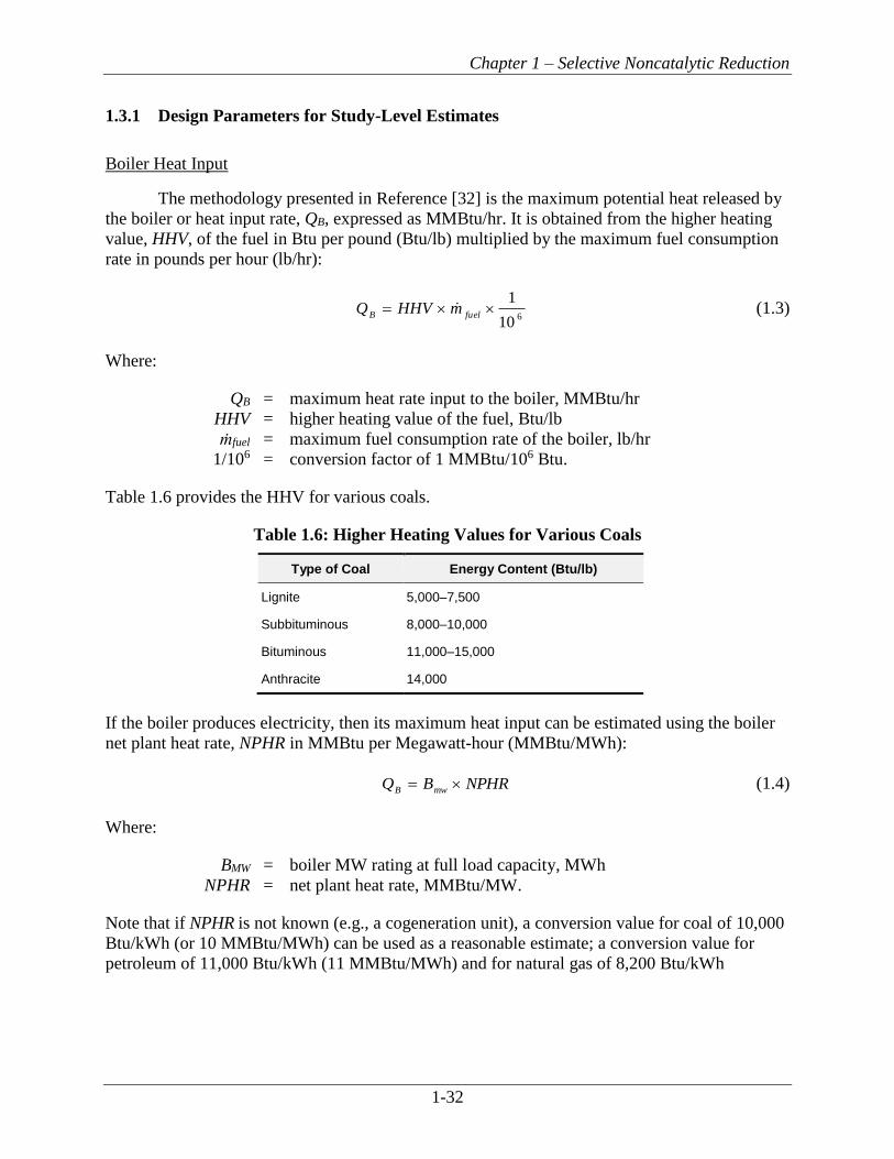
Chapter 1 – Selective Noncatalytic Reduction
1-32
1.3.1 Design Parameters for Study-Level Estimates
Boiler Heat Input
The methodology presented in Reference [32] is the maximum potential heat released by
the boiler or heat input rate, QB, expressed as MMBtu/hr. It is obtained from the higher heating
value, HHV, of the fuel in Btu per pound (Btu/lb) multiplied by the maximum fuel consumption
rate in pounds per hour (lb/hr):
6
10
1=
fuelBmHHVQ (1.3)
Where:
QB = maximum heat rate input to the boiler, MMBtu/hr
HHV = higher heating value of the fuel, Btu/lb
ṁfuel = maximum fuel consumption rate of the boiler, lb/hr
1/106 = conversion factor of 1 MMBtu/106 Btu.
Table 1.6 provides the HHV for various coals.
Table 1.6: Higher Heating Values for Various Coals
Type of Coal Energy Content (Btu/lb)
Lignite 5,000–7,500
Subbituminous 8,000–10,000
Bituminous 11,000–15,000
Anthracite 14,000
If the boiler produces electricity, then its maximum heat input can be estimated using the boiler
net plant heat rate, NPHR in MMBtu per Megawatt-hour (MMBtu/MWh):
NPHRBQmwB
= (1.4)
Where:
BMW = boiler MW rating at full load capacity, MWh
NPHR = net plant heat rate, MMBtu/MW.
Note that if NPHR is not known (e.g., a cogeneration unit), a conversion value for coal of 10,000
Btu/kWh (or 10 MMBtu/MWh) can be used as a reasonable estimate; a conversion value for
petroleum of 11,000 Btu/kWh (11 MMBtu/MWh) and for natural gas of 8,200 Btu/kWh
Chapter 1 – Selective Noncatalytic Reduction
1-33
(8.2 MMBtu/MWh) can be used [61].6 Using this value, the heat input rate, QB, for a coal-fired
unit is:
10=MWB
BQ (1.5)
Where:
10 = estimated NPHR for coal, MMBtu/MWh.
Heat Rate Factor
The heat rate factor (HRF) is the ratio of actual heat rate of the boiler, in terms of the
boiler NPHR in MMBtu/MWh, compared to a typical heat rate of 10 MMBtu/MWh. The
developers of the cost estimation methodology presented in section 1.4.1 determined that using
this ratio in the equation for capital costs helped account for observed differences in actual costs
for different coal-fired boilers. To maintain consistency with that approach, the same ratio (i.e.,
with 10 in the denominator) also has been used in the equations for oil and gas fired boilers in
section 1.4.1. The NPHR is simply the amount of fuel energy that a boiler consumes to generate
1 MWh of electricity and is determined based on measurements of the electricity generation and
fuel consumption over the same period of time. As noted above, if the NPHR is not known for a
particular boiler, use 10 MMBtu/MWh.
10
NPHRHRF = (1.6)
Where:
HRF = Heat rate factor
NPHR = net plant heat rate of the system to be costed, MMBtu/MWh
10 = in MMBtu/MWh, is the NPHR that is the basis of the SNCR base
module capital cost.
System Capacity Factor
The total system capacity factor, CFtotal, is a measure of the average annual use of the
boiler in conjunction with the SNCR system. CFtotal is given by:
CFtotal = CFplant × CFSNCR (1.7)
Where:
CFtotal = total system capacity factor
CFplant = boiler capacity, which is the ratio of the actual quantity of fuel burned
annually to the potential maximum quantity of fuel burned annually
6 In recent years (2003 to 2010), the average NPHR for coal has increased slightly (likely due to aging of
equipment), and the average NPHR for natural gas has decreased slightly (likely due to the increased use of
natural gas fuel and the installation of new equipment).

Chapter 1 – Selective Noncatalytic Reduction
1-34
CFSNCR, = SNCR system capacity factor, which is the ratio of the actual days of
SNCR operation annually to the total number of days per year (i.e.,
365 days).
For utility boilers, the capacity factor of the boiler, CFplant, is the ratio of actual quantity
of fuel burned annually to the potential maximum quantity of fuel burned annually in pounds (lbs), as
shown in Equation 1.8a:
)8760
=MW
output
plant(B
BCF (1.8a)
Where:
BMW = boiler MW rating at full load capacity, MWh
Boutput = annual actual MW output, MW/year.
Alternatively, for industrial and utility boilers, the capacity factor of the boiler, CFplant,
can be calculated as the ratio of actual quantity of fuel burned annually to the potential maximum
quantity of fuel burned annually in pounds (lbs), as shown in Equation 1.8b:
fuel
fuel
plantmannual maximum
malactualannuCF = (1.8b)
Where:
actual annual mfuel = annual actual fuel consumption rate of the boiler, lb
maximum annual mfuel = annual maximum fuel consumption rate of the boiler, lb.
SNCR can be operated year-round or only during the specified ozone season (usually 5 months in
length). The capacity factor for the SNCR system, CFSNCR, is the ratio of the actual number of
SNCR operating days, tSNCR, to the total number of days per year, 365 days:
365
SNCR
SNCR
tCF = (1.9)
Where:
tSNCR, = actual days of SNCR operation annually, days
365 = number of days in a year, days.
Uncontrolled NOx and Stack NOx
Uncontrolled NOx, represented as NOxin, is the NOx emission level in the flue gas exit
stream from a boiler prior to the SNCR system. Note that NOxin also accounts for combustion

Chapter 1 – Selective Noncatalytic Reduction
1-35
controls if the boiler is equipped with such controls. The uncontrolled NOx emission level,
obtained from analyzing the boiler flue gas stream, is generally given in lb/MMBtu of NO2 [62].
The stack NOx, represented as NOxout, is the required NOx emission limit at the stack
outlet. It is generally set by regulatory limits and also given in lb/MMBtu of NO2.
NOx Removal Efficiency
The NOx removal efficiency, represented as ηNOx, is determined from the uncontrolled
NOx level of the boiler at maximum heat input rate, CFplant = 1.0, and the required stack emission
limit using the following equation:
in
outin
x
x
xx
NONO
NONO −= (1.10)
Where:
ηNOx = NOx removal efficiency, fraction
NOxin = uncontrolled NOx level from the boiler, i.e., inlet NOx rate to the
SNCR, lb/MMBtu (at maximum heat input rate, CFplant = 1.0)
NOxout = outlet NOx rate from the SNCR, lb/MMBtu.
NOx Removal Rates
The tons of NOx removed annually are:
NOx Removed/yr = NOxin NOx QB top/ 2,000 (1.11)
Where:
NOx Removed/yr = annual mass of NOx removed by the SNCR, tons/yr
QB = maximum potential heat input rate of the boiler, MMBtu/hr
top = operating time per year (CFtotal x 8760), hr/yr
2000 = conversion factor for lb/ton.
The pounds of NOx removed per hour (lb/hr) are:
NOx Removed/hr = NOxin NOx QB (1.12)
Where:
NOx Removed/hr = hourly mass of NOx removed by the SNCR, lb/hr
NOxin = uncontrolled NOx of the boiler, lb/MMBtu (at maximum heat input
rate, CFplant = 1.0)
NOx = NOx removal efficiency of the SNCR, expressed as a fraction
QB = heat input rate, MMBtu/hr.

Chapter 1 – Selective Noncatalytic Reduction
1-36
Normalized Stoichiometric Ratio
The normalized stoichiometric ratio, NSR, indicates the actual amount of reagent needed
to achieve the targeted NOx reduction. The actual quantity of reagent is greater than the
theoretical quantity due to reaction kinetics (see Section 1.2.3, Performance Parameters). NSR is
defined as:
x
NOeduncontrollofmoles
injectedNHequivalentofmolesNSR 3= (1.13)
For estimating purposes, the moles of NOx are equivalent to the moles of NO2. Note that the
moles of equivalent NH3 in Equation 1.13 are the moles of NH2 that will be released from the
reagent.
The actual stoichiometric ratio, ASR, is defined as:
xNOeduncontrollofmoles
injectedreagentofmolesASR = (1.14)
ASR can also be calculated from the NSR using the following equation:
T
SR
NSRASR = (1.15)
Where SRT is the theoretical stoichiometric ratio, the ratio of equivalent moles of NH3 per mole
of reagent injected. From the chemical formulas for ammonia (NH3) and urea [CO(NH2)2] given in
the reaction Equations 1.1 and 1.2, SRT is 1 for ammonia and 2 for urea.
Reagent utilization is the ratio of moles of reagent reacted to the moles injected. This
indicates how much reagent is being reacted versus how much reagent is passing through as
ammonia slip. Utilization of reagent can be calculated from NSR and the NOx reduction
efficiency as follows:
NSR
nUtilizatioxNO
= (1.16)
The derivation for this equation is presented in Reference [24].
Methods for estimating NSR are considered proprietary. A simplified NSR estimation
procedure was developed by The Cadmus Group, Bechtel Power, Inc., and SAIC in the EPA
draft report, Selective Noncatalytic Reduction for NOx Control on Coal-fired Boilers [32]. This
procedure was developed using linear regression and NSR data from References [62] and [63].
The values of NSR derived using this approach should not be used for equipment design or
guarantee purposes.

Chapter 1 – Selective Noncatalytic Reduction
1-37
The NSR estimation equation is valid from 0 to 50% NOx reduction [32]. The equation
used to estimate NSR for urea reagent is where NOxin is given in lb/MMBtu.
in
xin
x
NOX
NO
NONSR
]7.02[ += (1.17)
Figure 1.10 provides a graphical representation of this NSR estimation method. Generally, the
value of NSR ranges from 0.5 to 2.0 in industrial and utility boilers with utilization ranging from
25 to 50%.
Figure 1.10: Approximate NSR Estimation for Urea [32]
In a design developed by a system supplier, NSR would be adjusted to account for several
parameters that are not included in the NSR estimation equation. The following parameters are
used by the system supplier to more accurately predict NSR for a given boiler:
▪ Reaction temperature range available within the boiler superheater (radiative and convective
section) and primary reheater (convective section or cavity) region. If the required
temperature window occurs in the radiant section of the boiler, NSR could decrease.
However, if the temperature window occurs in the convective section, NSR may increase.
▪ Residence time available in the desirable temperature range. The required NSR decreases
as the available residence time increases.
▪ Degree of mixing between the injected chemical and the flue gases. NSR decreases as the
degree of mixing increases.
▪ Ammonia slip vs. required NOx reduction. Tighter constraints on ammonia slip would
dictate lower NSRs, thereby limiting the achievable NOx reduction. In addition, ASM
equipment may need to be installed as ammonia slip constraints become tighter.
0.40
0.60
0.80
1.00
1.20
1.40
1.60
1.80
2.00
0.4 0.5 0.6 0.7 0.8 0.9 1 1.1 1.2 1.3 1.4
Pre
dic
ted
NSR
Uncontrolled NOx (lb/MMBtu)
25%
30%
35%
40%
45%
50%
NOx Reduction
Chapter 1 – Selective Noncatalytic Reduction
1-38
Estimating Reagent Consumption and Tank Size
Once NSR is estimated, the rate of reagent consumption or mass flow rate of the reagent,
reagentm expressed as lb/hr, can be calculated using:
TNO
reagentBx
reagentSRM
MNSRQNOm
x
in
= (1.18)
Where:
ṁreagent = mass flow rate, or consumption rate, of the reagent, lb/hr
Mreagent = the molecular weight of the reagent (60.06 grams per mole [g/mole]
for urea, 17.03 g/mole for ammonia)
MNOx = the molecular weight of NO2 (46.01 g/mole).
In this equation, the molecular weight of NO2 is used because the NOx emissions, NOxin, are
given in lb/MMBtu of NO2. As stated previously, SRT is the ratio of equivalent moles of NH3 per
mole of reagent (1 for ammonia and 2 for urea).
For urea or ammonia, the mass flow rate of the aqueous reagent solution is given by:
sol
reagent
solC
mm
= (1.19)
Where:
ṁsol = mass flow rate of the aqueous reagent solution, lb/hr
Csol = the concentration of the aqueous reagent solution, by weight fraction.
The solution volume flow rate qsol, generally expressed as gallons per hour (gph), is given by:
4805.7=sol
sol
sol
mq
(1.20)
Where:
qsol = solution volume flow rate, gph
sol = the density of the aqueous reagent solution, lb/ft3
7.4805 = conversion factor of 7.4805 gal/1 ft3.
The density is 71.0 lb/ft3 for 50% urea and 56 lb/ft3 for 29% ammonia.
The total volume stored in the tank, or tanks, is based on the volume that the SNCR
system requires to operate for a specified number of days. The volume stored onsite for the
number of operating days, tstorage, is:

Chapter 1 – Selective Noncatalytic Reduction
1-39
24tan
=storagesolk
tqVol (1.21)
Where:
Voltank = total volume of aqueous solution stored in the tank(s), gallons (gal)
tstorage = number of operating days the SNCR is required to operate between
solution delivery, days
24 = conversion factor of 24 hr/1 day.
Note that the tank volume is typically based on the maximum annual heat input rate, so the
capacity factor is not included in Equation 1.21. A common onsite storage requirement is for
14 days (or 1–3 weeks) of SNCR operation.
1.3.2 Design Parameters for Detailed/Performance Specifications
Cost Estimates Based on Detailed Specifications
This subsection describes the information that must be assembled and furnished to a
supplier to prepare design specifications, particularly the component information with the
greatest influence on system cost. SNCR capital and operating costs can be estimated if the
major cost items are identified and the system is defined in adequate detail [32]. The following
data are provided to the system supplier for SNCR system design:
▪ The boiler capacity in terms of heat input rate (MMBtu/hr);
▪ Boiler capacity profile – percent of time the boiler operates at a given heat input rate;
▪ Type of combustion unit – dry/wet bottom boiler, wall-fired, tangentially fired, cyclone
fired, other (e.g., stoker fired); year built; and manufacturer;
▪ Boiler dimensions – sectional side view, sectional front view, plan section through furnace
(width × depth), furnace height (floor to furnace exit), firing zone height, sections through
radiant and connective heat transfer cavities (zones), other unique features (e.g., division
wall/panels) in the furnace or backpass;
▪ Locations of boiler furnace overfire air ports;
▪ Locations and sizes of boiler observation ports, temperature probe ports, soot blower
openings, and other locations for potential new ports;
▪ Air preheater design and operational data, including soot blower data;
▪ Fuel data – proximate and ultimate analyses and HHV for primary and secondary fuels;
▪ Fuel firing rates at full and partial loads (e.g., 100%, 70%, and 30%);
▪ Test data or combustion calculations – flue gas flow rate at design or actual conditions;
excess air rate at full and partial loads; flue gas composition including O2, NOx, CO, SO2,
and HCl;
▪ Flue gas temperature profile from furnace exit to economizer (i.e., where temperature
drops to about 1400°F [760°C]) at various loads;

Chapter 1 – Selective Noncatalytic Reduction
1-40
▪ Flue gas residence time – available flue gas residence time in the upper furnace and
convective pass within the temperature window for urea at various loads;
▪ Existing or planned uncontrolled NOx and CO emission data in ppm or lb/MMBtu without
the proposed SNCR system, including any change in emissions related to other installed or
planned technologies (e.g., LNB, gas recirculation). This should be specified for boiler operations
at full load and selected partial loads;
▪ Minimum expected NOx reduction or permit requirement for stack NOx emission level
(ppm or lb/MMBtu). This should be specified for boiler operations at full load and selected
partial loads; and
▪ Allowable byproduct emission rates for regulated emissions such as ammonia.
The boiler supplier/manufacturer can furnish most of this information for existing or planned
new units. For fuel data, the designer needs typical or design values, as well as the expected
range. To define the temperature and flue gas velocity profiles in existing boilers, it is preferable
to obtain actual measurements.
To obtain a representative cost quotation from an SNCR system supplier, the request
should contain sufficient details to minimize design assumptions by the supplier. The request for
quotation should include the technical specifications, as well as commercial terms and
conditions.
Two important parts of the specification are work included in the scope of the supplier
and work not included (i.e., work performed by the owner/operator). The more precise and
detailed the specification of the work, the more accurate the overall system design and cost. For a
turnkey scope (design, supply, and erect all equipment, and demonstrate commercial operation
while meeting all performance criteria), the excluded work is minimal.
Cost Estimates Based on Performance Specifications
Preparation of detailed specifications involves significant time and effort (for both owner
and supplier) and is not critical for study-level cost estimates. To simplify the process, a
performance specification approach may be used in the request for quotation. In this approach,
the basic required plant and fuel data are provided along with the required SNCR system
performance requirements, excluding equipment-related details (e.g., materials of construction,
equipment redundancy, and level of instrumentation and controls) [32].
The performance specification should include a description of the system and
components in enough detail to understand the type and quality of system proposed by the
supplier. A cost breakdown of major components and subsystems also should be obtained from
the supplier to enable independent assessment, deletion, or addition, and to compare other bids
on an equitable basis. The SNCR performance specification typically should request the
following items regarding NOx emission control performance, chemical consumption, and other
consumption rates at full and partial loads:
▪ Guaranteed and expected NOx emission rates in units of lb/MMBtu and lb/hr with
averaging period as defined in the air quality permit of the facility;

Chapter 1 – Selective Noncatalytic Reduction
1-41
▪ Guaranteed and expected NH3 slip, ppm and location where the slip will be measured (other
conditions such as dry basis, percent O2, per the air permit);
▪ Other emission limits as specified (or anticipated) in the permit;
▪ NSR proposed to achieve the required NOx reduction;
▪ Guaranteed and expected reagent consumption rate;
▪ Guaranteed and expected dilution air, steam, or water consumption rate;
▪ Atomizing and cooling air (or steam) pressure and consumption rate; and
▪ Guaranteed and expected electrical power consumption.
1.4 Cost Analysis
The presence of different boiler configurations, fuel use, and various site-specific
conditions produces variability in the cost and cost-effectiveness of SNCR. For utility boilers
with capacity of 100 MW, the capital cost ranges from $35 to $44/kW, for 400 MW boilers the
capital cost ranges from $9 to $13/kW, and for 700 MW boilers ranges from $4 to $7/kW [13].7
For industrial boilers, cost data are provided in Table 1.3. For coal-fired industrial boilers of 100
to 1,000 MMBtu/hr, the capital cost ranges from $2,600 to $5,300/MMBtu/hr, and for gas and
oil-fired industrial boilers, ranges from $2,000 to $4,200/MMBtu/hr [19].
The cost estimating methodology presented here provides a tool to estimate study-level
SNCR capital and annual costs. Actual selection of the most cost-effective option should be
based on a detailed engineering study and cost quotations from system suppliers. The costing
methodology was developed to estimate capital costs in 2016 dollars (2016$).
The capital cost equations are based on the EPA Clean Air Markets Division (CAMD)
Integrated Planning Model [11]. In the costing method for SNCR from the IPM, the purchased
equipment cost, the direct installation cost, and the indirect installation cost are estimated
together. This methodology is somewhat different from the EPA Air Pollution Control Cost
Manual methodology, which estimates equipment costs and installation costs separately.
The capital cost equations are applicable to utility boilers with full load capacities greater
than or equal to (≥) 25 MW. The capital costs estimated by the equation represent typical costs
for retrofits at existing boilers, however, these equations are appropriate for both new units and
retrofit units [11]. The cost equations are sufficient for NOxout emission reductions of 25% for
Pulverized Coal and 50% for Fluidized Bed [11]. The SNCR system design used for the cost
estimate is a urea-based system. An ammonia-based system would have different storage,
distribution, and injection equipment costs. Allowed ammonia slip for the SNCR system ranges
from 2–10 ppm [32].
Capital cost equations are provided for coal-fired units. Capital cost equations are
provided for fluidized bed (FB) boiler units and for other boiler types (i.e., non-FB boiler units
such as cyclone, wall-fired, tangential-fired, etc.). In general, SNCR units for FB boilers are less
expensive than for other boiler types. The cost equations are sufficient for NOxout emission levels
as low as 0.08 lb/MMBtu for FB and 0.1 lb/MMBtu for nonFB [11]. The cost equations are
7 Cost years for these data range from 2005 to 2007.

Chapter 1 – Selective Noncatalytic Reduction
1-42
applicable to retrofit of SNCR on existing boilers. The cost estimating procedure, however, is
suitable for retrofit or new boiler applications of SNCR on all types of coal-fired electric utilities
and large industrial boilers. The increased cost due to retrofit is minimal; approximately 10–30%
of the cost of SNCR applied to a new boiler [12].
1.4.1 Total Capital Investment
Total capital investment (TCI) includes direct and indirect costs associated with
purchasing and installing SNCR equipment. Costs include the equipment cost for the SNCR
system itself, the cost of auxiliary equipment, direct and indirect installation costs, additional
costs due to installation, costs for buildings and site preparation, offsite facilities, land, and
working capital. In general, SNCR does not require buildings, site preparation, offsite facilities,
land, or working capital. A more detailed discussion of capital costs can be found in Section 1,
Chapter 2 of this Manual. The total project cost or TCI for the SNCR is based on the approach
used by EPA CAMD in the Integrated Planning Model version 6 (IPM v6) [11], and this
approach includes both the direct capital costs and the indirect capital costs for coal-fired utility
boilers. Cost estimates are available for different size categories of coal-fired utility boilers.
Costs for oil- and gas-fired utility boilers have also been included in this SNCR section. While
the IPM v6 approach does not include capital cost equations for utility oil- and gas-fired units, it
was assumed that the costs for utility oil- and gas-fired units are slightly less than costs for FB
coal-fired units.8 For oil- and gas-fired units, the appropriate NPHR value for oil (average value
of 11 MMBtu/MWh) and for natural gas (average 8.2 MMBtu/MWh) should be used. Cost
estimates are available for different size categories utility oil- and gas-fired units. Since the IPM
is based primarily on data for retrofits and retrofits are typically 9 to 23 percent more than for
new units of the same size and design, we have included a retrofit factor in the TCI equations
[12]. A retrofit factor of 0.84 should be used for new construction and a retrofit factor of 1
should be used for SNCR retrofits to existing boilers, where the retrofit is of an average level of
difficulty.
In addition, costs for different size categories of industrial boilers9 have been included in
this SNCR section. IPM v6 does not contain cost procedures for industrial boilers; however,
based on analysis of data in Table 1.3, costs for industrial boilers (in the 100 MMBtu/hr to 1000
MMBtu/hr range) appear to range between significantly less than costs for utility boilers to
essentially the same as the cost for utility boilers. The procedure described in this document
assumes the costs for industrial boilers are essentially the same as for utility boilers for the same
design heat input. On average, this costing approach may result in a slight overestimate of costs
for industrial boilers. The equipment costs of installing SNCRs on industrial boilers may be less
than the costs for installing an SNCR on the same size utility boiler because (1) the narrower
load operating range for boilers requires fewer injectors; and (2) higher allowable ammonia slip
for some industrial boilers reduces the complexity of system controls.
The SNCR costs are impacted by the unit’s elevation with respect to sea level. These cost
calculations have been developed for SNCR systems located within 500 feet of sea level. For
8 When using the IPM v3 procedures, capital costs for non-fluidized bed coal-fired boilers were approximately 1.5
times higher than the costs for oil- and gas-fired boilers. The procedure described here maintains approximately
the same ratio. 9 By “industrial,” the reference is to industrial, commercial, and institutional (or ICI) boilers.

Chapter 1 – Selective Noncatalytic Reduction
1-43
SNCR systems located at higher elevations, the base cost should be increased based on the ratio
of the atmospheric pressure between sea level and the location of the system, i.e., atmospheric
pressure at sea level divided by atmospheric pressure at elevation of unit, as shown in Equation
1.22. [11]
ELEVP
PELEVF 0= (1.22)
Where:
ELEVF = elevation factor
P0 = atmospheric pressure at sea level, 14.7 pounds per square inch absolute
(psia)
PELEV = atmospheric pressure at elevation of the unit, psia.
The PELEV can be calculated using the following equation [64]:
144
1
6.518
7.459)00356.0(592116
256.5
+−=
hPELEV
(1.23)
Where:
PELEV = atmospheric pressure at elevation of the unit, psia
h = altitude, feet.
1.4.1.1 Utility Boilers, Coal-fired Units
Utility, coal-fired units ≥25 MW. The capital cost equation for coal-fired units ≥25 MW
is as follows:
( )CostCostCost
BOPAPHSNCRTCI ++= 3.1 (1.24)
Where:
TCI = total capital investment for a SNCR on a boiler, $
SNCRCost = cost of the SNCR, $
APHCost = air pre-heater cost, $
BOPCost = balance of plant costs, $.
The TCI calculation shown in Equation 1.25 includes a factor of 1.3 to estimate
engineering and construction management costs, installation, labor adjustment for the SNCR,
and contractor profit and fees. The owner’s costs (for owner activities related to engineering,
management, and procurement) and costs such as allowance for funds used during construction
(AFUDC) are capital cost items that are not included in the EPA Control Cost Manual
Chapter 1 – Selective Noncatalytic Reduction
1-44
methodology and are inconsistent with the overnight cost method10 that is a basis for the Control
Cost Manual methodology, and thus are not included in the TCI estimates in this section or in
other Control Cost Manual chapters.
SNCR costs, utility, coal-fired units ≥25 MW. The capital costs for the SNCR base unit
includes costs for the injectors, blowers, distributive control system (DCS), and the reagent
system [11]. The SNCR costs are calculated as follows:
( ) RFELEVFBTFCoalFHRFBSNCRMWCost
=42.0
000,220 (1.25)
Where:
SNCRCost = SNCR unit costs, $
220,000 = constant in the equation
BTF = boiler type factor (BTF=1 if non-FB boiler; BTF=0.75 for FB boiler)
BMW = boiler MW rating at full load capacity for the unit being costed, MW
HRF = heat rate factor
CoalF = coal factor (CoalF=1 if bituminous; CoalF=1.05 if PRB; CoalF=1.07 if
Lignite)
ELEVF = elevation factor (calculated using Equation 1.22 if plant is located
above 500 feet above sea level; ELEVF = 1 for plants located at or
below 500 ft above sea level)
RF = retrofit factor (RF = 0.84 for new construction; RF = 1 for retrofits
with average level of difficulty).
The boiler type factor, BTF, is based on the type of boiler unit. Boiler types may be
fluidized bed or non-fluidized bed. Non-FB units include cyclone, tangentially-fired, wall-fired
boiler units. Fluidized bed units include circulating, bubbling, atmospheric, and pressurized
units. The BTF is 1 for non-FB boilers and is 0.75 for FB boilers. The CoalF is 1 for bituminous
coal, 1.05 for powder river basin (PRB) coal and 1.07 for lignite coal.
Air Pre-Heater Modification costs, utility, coal-fired units ≥25 MW. Air pre-heater
modification costs are included only where SO3 control is necessary. An air pre-heater
modification is necessary for the control of SO3 for boilers that burn bituminous coal where the
SO2 content of the coal is 3 lb/MMBtu or greater. If other coal types are used, then no air pre-
heater modification is needed. The air pre-heater modification costs are calculated as follows:
( ) RFAHFCoalFHRFBAPHMWCost
=78.0
000,69 (1.26)
Where:
10 The overnight cost estimation method presumes costs are incurred as if the project in question incurred no interest
during construction,or was built “overnight.” Another description of this method is the present value of cost that
would have to be paid as a lump sum up front to completely pay for a construction project. For more information,
see “Conducting Technical and Economic Evaluations – As Applied for the Process and Utility Industries,”
Recommended Practice 16R-90, American Association of Cost Engineering International. April, 1991.

Chapter 1 – Selective Noncatalytic Reduction
1-45
APHCost = Air pre-heater cost, $
69,000 = constant in the equation
AHF = air heater factor (AHF=1 if bituminous coal and SO2 ≥3 lb/MMBtu; if
not true, AHF=0)
RF = retrofit factor (RF = 0.84 for new construction; RF = 1 for retrofits
with average level of difficulty).
The AHF is 1 for bituminous coal and where the SO2 content of the coal is 3 lb/MMBtu or
greater. If the boiler burns other coal types, then the AHF is 0 and this term drops out of the
overall SNCRCost equation.
Balance of plant (BOP) costs, utility, coal-fired units ≥25 MW. The BOP costs include
cost items such as piping, water treatment for dilution water, ductwork, auxiliary power
modifications, and other electrical and site upgrades that are typically necessary as part of the
installation of the SNCR unit [11]. The BOP costs are calculated as follows:
( ) ( ) RFBTFNOBBOPxMWCost
=12.033.0
Removed/hr000,320 (1.27)
Where:
BOPCost = Balance of plant costs, $
320,000 = constant in the equation
NOx Removed/hr = hourly mass of NOx removed by the SNCR system, lb/hr
RF = retrofit factor (RF = 0.84 for new construction; RF = 1 for retrofits
with average level of difficulty).
1.4.1.2 Utility boilers, Oil- and gas-fired units
Utility, oil- and gas-fired units ≥25 MW. The capital cost equation for oil- and gas-fired
boilers ≥100 MW is based on the utility boiler equations for fluidized bed boilers. Because oil
and natural gas are the fuel inputs and not coal, it is assumed that no modifications are needed
for the air pre-heater. The capital cost equation for oil- and gas-fired units is as follows:
( )CostCost
BOPSNCRTCI += 3.1 (1.28)
Where:
TCI = total capital investment for a SNCR on a boiler, $
SNCRCost = cost of the SNCR, $
BOPCost = balance of plant costs, $.
This TCI includes engineering and construction management costs, installation, labor
adjustment for the SNCR, and contractor profit and fees.
SNCR costs, utility oil- and gas-fired units ≥25 MW. The capital costs for the SNCR base
unit includes costs for the injectors, blowers, distributive control system (DCS), and the reagent
system [11]. The SNCR costs are calculated as follows:

Chapter 1 – Selective Noncatalytic Reduction
1-46
( ) RFELEVFHRFBSNCRMWCost
=42.0
000,147 (1.29)
Where:
SNCRCost = SNCR unit costs, $
147,000 = constant in the equation
BMW = boiler MW rating at full load capacity for the unit being costed, MW
HRF = heat rate factor
ELEVF = elevation factor (calculated using Equation 1.22 if plant is located
above 500 feet above sea level; ELEVF = 1 for plants located at or
below 500 feet above sea level)
RF = retrofit factor (RF = 0.84 for new construction; RF = 1 for retrofits
with average level of difficulty).
Balance of plant (BOP) costs, utility oil- and gas-fired units ≥25 MW. The BOP costs
include cost items such as piping, water treatment for dilution water, ductwork, auxiliary power
modifications, and other electrical and site upgrades that are typically necessary as part of the
installation of the SNCR unit [11]. The BOP costs are calculated as follows:
( ) ( ) RFhrmovedNOBBOPxMWCost
=12.033.0
/Re000,213 (1.30)
Where:
BOPCost = Balance of plant costs, $
213,000 = constant in the equation
NOx Removed/hr = hourly mass of NOx removed by the SNCR system, lb/hr
RF = retrofit factor (RF = 0.84 for new construction; RF = 1 for retrofits
with average level of difficulty).
1.4.1.3 Industrial Boilers, Coal-fired Units
Industrial, coal-fired units ≥250 MMBtu/hr. The capital cost equation for industrial coal-
fired boilers ≥250 MMBtu/hr is as follows:
( )CostCostCost
BOPAPHSNCRTCI ++= 3.1 (1.31)
Where:
TCI = total capital investment for a SNCR on a boiler, $
SNCRCost = cost of the SNCR, $
APHCost = air pre-heater cost, $
BOPCost = balance of plant costs, $.
This TCI includes engineering and construction management costs, installation, labor
adjustment for the SNCR, and contractor profit and fees.

Chapter 1 – Selective Noncatalytic Reduction
1-47
SNCR costs, industrial, coal-fired units ≥250 MMBtu/hr. The capital costs for the SNCR
base unit includes costs for the injectors, blowers, distributive control system (DCS), and the
reagent system [11]. The SNCR costs are calculated as follows:
( ) RFELEVFBTFCoalFHRFQSNCRBCost
=42.0
1.0000,220 (1.32)
Where:
SNCRCost = SNCR unit costs, $
220,000 = constant in the equation
QB = maximum heat rate input to the boiler, MMBtu/hr
HRF = heat rate factor
CoalF = coal factor (CoalF=1 if bituminous; CoalF=1.05 if PRB; CoalF=1.07 if
Lignite)
BTF = boiler type factor (BTF=1 if non-FB boiler; BTF=0.75 for FB boiler)
ELEVF = elevation factor (calculated using Equation 1.22 if plant is located
above 500 feet above sea level; ELEVF = 1 for plants located at or
below 500 feet above sea level)
RF = retrofit factor (RF= 0.84 for new construction; RF = 1 for retrofits with
average level of difficulty).
The boiler type factor, BTF, is based on the type of boiler unit. Boiler types may be
fluidized bed or non-fluidized bed. Non-FB units include cyclone, tangentially-fired, wall-fired
boiler units. Fluidized bed units include circulating, bubbling, atmospheric, and pressurized
units. The BTF is 1 for non-FB boilers and is 0.75 for FB boilers. The CoalF is 1 for bituminous
coal, 1.05 for powder river basin (PRB) coal, and 1.07 for lignite coal.
Air Pre-Heater Modification costs, industrial, coal-fired units ≥250 MMBtu/hr. Air pre-
heater modification costs are included only where SO3 control is necessary. An air pre-heater
modification is necessary for the control of SO3 for boilers that burn bituminous coal where the
SO2 content of the coal is 3 lb/MMBtu or greater. If other coal types are used, then no air pre-
heater modification is needed. The air pre-heater modification costs are calculated as follows:
( ) RFAHFCoalFHRFQAPHBCost
=78.0
1.0000,69 (1.33)
Where:
APHCost = Air pre-heater cost, $
69,000 = constant in the equation
AHF = air heater factor (AHF=1 if bituminous coal and SO2 ≥3 lb/MMBtu; if
not true, AHF=0)
RF = retrofit factor (RF = 0.84 for new construction; RF = 1 for retrofits
with average level of difficulty).

Chapter 1 – Selective Noncatalytic Reduction
1-48
The AHF is 1 for bituminous coal and where the SO2 content of the coal is 3 lb/MMBtu
or greater. If the boiler burns other coal types, then the AHF is 0 and this term drops out of the
overall SNCRCost equation.
Balance of plant (BOP) costs, industrial, coal-fired units ≥250 MMBtu/hr. The BOP costs
include cost items such as piping, water treatment for dilution water, ductwork, auxiliary power
modifications, and other electrical and site upgrades that are typically necessary as part of the
installation of the SNCR unit [11]. The BOP costs are calculated as follows:
( ) ( ) RFBTFNOQBOPxBCost
=12.033.0
Removed/hr1.0000,320 (1.34)
Where:
BOPCost = Balance of plant costs, $
320,000 = constant in the equation
NOx Removed/hr = hourly mass of NOx removed by the SNCR system, lb/hr
RF = retrofit factor (RF = 0.84 for new construction; RF = 1 for retrofits
with average level of difficulty).
1.4.1.4 Industrial Boilers, Oil- and Gas-fired Units
Industrial, oil- and gas-fired units ≥250 MMBtu/hr. The capital cost equation for
industrial oil- and gas-fired boilers ≥250 MMBtu/hr is based on the utility boiler equations. The
capital cost equation for oil- and gas-fired units is as follows:
( )CostCost
BOPSNCRTCI += 3.1 (1.35)
Where:
TCI = total capital investment for a SNCR on a boiler, $
SNCRCost = cost of the SNCR, $
BPCost = balance of plant costs, $.
This TCI includes engineering and construction management costs, installation, labor
adjustment for the SNCR, and contractor profit and fees.
SNCR costs, industrial, oil- and gas-fired units ≥250 MMBtu/hr. The capital costs for the
SNCR base unit includes costs for the injectors, blowers, distributive control system (DCS), and
the reagent system [11]. The SNCR costs are calculated as follows:
RFELEVFHRFNPHR
QSNCR B
Cost
=
42.0
000,147 (1.36)
Where:
SNCRCost = SNCR unit costs, $
Chapter 1 – Selective Noncatalytic Reduction
1-49
147,000 = constant in the equation
QB = maximum heat rate input to the boiler, MMBtu/hr
NPHR = net plant heat rate, MMBtu/MWh (use 11 for oil-fired units and 8.2 for
gas-fired units, if actual values are not available)
HRF = heat rate factor
ELEVF = elevation factor (calculated using Equation 1.22 if plant is located
above 500 feet above sea level; ELEVF = 1 for plants located at or
below 500 feet above sea level)
RF = retrofit factor (RF = 0.84 for new construction; RF = 1 for retrofits
with average level of difficulty).
Balance of plant (BOP) costs, industrial, oil- and gas-fired units ≥250 MMBtu/hr. The
BOP costs include cost items such as piping, water treatment for dilution water, ductwork,
auxiliary power modifications, and other electrical and site upgrades that are typically necessary
as part of the installation of the SNCR unit [11]. The BOP costs are calculated as follows:
( ) RFNONPHR
QBOP
x
B
Cost
=
12.0
33.0
Removed/hr000,213 (1.37)
Where:
BPC = Balance of plant, $
213,000 = constant in the equation
NOx Removed/hr = hourly mass of NOx removed by the SNCR system, lb/hr
RF = retrofit factor (RF = 0.84 for new construction; RF = 1 for retrofits
with average level of difficulty).
1.4.2 Total Annual Costs
Total annual costs (TAC) consist of direct costs, indirect costs, and recovery credits.
Direct annual costs are those associated or proportional to the quantity of waste gas processed by
the control system. Indirect (fixed) annual costs are independent of the operation of the control
system and would be incurred even if it were shut down. No byproduct recovery credits are
included because there are no salvageable byproducts generated from the SNCR [24]. Each of
these costs is discussed in the sections below. A more detailed discussion of annual costs can be
found in Section 1, Chapter 2 of this Cost Manual.
Design parameters are estimated using the maximum annual heat input rate of the boiler
to ensure adequate sizing of the SNCR system. Annual costs are calculated using the average
heat input rate of the boiler and SNCR system using CFtotal. This ensures that annual costs are
based on the actual operating conditions rather than the design case.
Direct Annual Costs
Direct annual costs (DAC) include variable and semivariable costs. Variable direct annual
costs account for purchase of reagent, utilities (electrical power and water), and any additional
coal and ash disposal resulting from the operation of the SNCR. Semivariable direct annual costs

Chapter 1 – Selective Noncatalytic Reduction
1-50
include operating and supervisory labor and maintenance (labor and materials). These costs are
discussed individually below.
+
+
+
+
+
=
Cost
Ash
Annual
Cost
Coal
Annual
Cost
Water
Annual
Cost
yElectricit
Annual
Cost
Reagent
Annual
Cost
eMaintenanc
Annual
DAC (1.38)
Operating and Supervisory Labor
In general, no additional personnel are required to operate or maintain the SNCR equipment
for large industrial facilities. Therefore, the cost of operating or supervisory labor is assumed to
be negligible.
Maintenance
The annual maintenance labor and material cost, including nozzle tip replacement for the
injectors, is assumed to be 1.5% of the TCI in dollars. This is a fairly standard percentage for
maintenance on control devices, but for SNCR it may be conservative (i.e., overstate the cost)
because one study indicates that a lower percentage is reasonable [11]. The equation for annual
maintenance cost in $/hr, AMC, is given by:
Annual maintenance cost = 0.015 × TCI (1.39)
Reagent Consumption
The annual cost of reagent purchase in $/yr is estimated using the aqueous reagent
volume flow rate in gallons per hour (gph,) qsol , and the total operating time, top, in hours, and
Costreag is the cost of reagent in dollars per gallon ($/gal):
Annual reagent cost = qsol × Costreag × top (1.40)
The operating time per year, top, is estimated using the capacity factor, CFtotal:
yr
hr760,8CFt
totalop=
(1.41)
For pelletized urea or anhydrous ammonia, the m reagent calculation would need to be
adjusted according to the cost of the reagent and Equation 1.18 above; however, since these are
not the least costly reagent choices, these costs are not addressed here.
Utilities
The electrical power consumption, P, in kilowatts (kW) estimated for SNCR operations is
derived in Appendix B of the draft EPA report, Selective Noncatalytic Reduction for NOx

Chapter 1 – Selective Noncatalytic Reduction
1-51
Control on Coal-fired Boilers [32]. It is based on a linear regression of electrical power
consumption data correlated to the uncontrolled NOx emission level in lb/MMBtu, NOxin, the NSR
and the boiler heat input in MMBtu/hr, QB:
NPHR
QNSRNOP
Bxin
=47.0
(1.42)
Where:
P = electrical power consumption of the SNCR, kW
0.47 = constant in the equation
NPHR = net plant heat rate, MMBtu/MWh.
Using the estimated power consumption, P, the annual cost of electricity is estimated
from the following equation:
Annual electricity cost =P × Costelect × top (1.43)
Where:
Costelect = cost of electricity in dollars per kWh ($/kWh).
Water Consumption
The volumetric flowrate of water for diluting the urea is calculated from the aqueous urea
mass flow rate in lb/hr and the concentration of the aqueous urea during storage, Curea sol stored and
the average percent concentration of the injected urea, Curea sol inj. The flowrate, qwater, in gallons per
hour (gph) is:
−= 1
injsolurea
storedsolurea
water
sol
waterC
Cmq
(1.44)
Where:
qwater = flowrate of water necessary for diluting the reagent solution, gph
water = the density of water, 8.345 lb/gal
Curea sol stored = concentration of the aqueous solution as stored, weight fraction
Curea sol inj. = concentration of the aqueous solution as injected, weight fraction.
For urea dilution from a 50% solution to a 10% solution, Equation 1.44 becomes:
water
sol
water
mq
4= (1.45)
Chapter 1 – Selective Noncatalytic Reduction
1-52
Using this estimate for the volume flow rate of water (gph), the annual cost of water
consumption in $/yr is given by:
Annual water cost = qwater × Cost water × top (1.46)
where Costwater is the cost of water in dollars per gallon ($/gal) and top is given by Equation 1.43.
Additional Fuel to Vaporize Water in Reagent Solution
The additional fuel required as a result of the heat used to evaporate the water in the
injected solution (water in the stored urea solution and the dilution water) is estimated using the
following equation:
−= 1
1
injsolurea
reagentC
mHvFuel (1.47)
Where:
ΔFuel = fuel required to evaporate the injected solution water, Btu/hr
HV = the heat of vaporization of water, Btu/lb.
Curea sol inj is the percent concentration of the injected aqueous urea agent and m reagent is the
mass flowrate in lb/hr. The approximate HV at 310°F (150°C) is 900 BTU/lb, which is a
representative temperature for flue gas exiting the air heater.
Although the water from the urea solution is evaporated in the furnace at higher
temperatures (due to urea injection in the furnace zones at over 1500°F [820°C]), the temperature
at the air heater exit is used because it is the thermodynamic end point of the combustion
process. The quantity of fuel burned in the boiler depends on the boiler efficiency, which in turn
depends on the air heater exit temperature and the moisture in the air heater exit gas. The boiler
is fired to maintain the required steam flow (e.g., for the steam turbine). Because the water from
the urea solution evaporates in the boiler, the boiler efficiency decreases. Consequently, more
fuel needs to be burned to maintain the required steam flow.
With urea as the reagent, injected as a 10% solution and HV = 900 Btu/lb, Equation 1.47
in MMBtu per hour becomes:
=
MMBtu
Btu
hr
lbm
lb
Btu
hr
MMBtuFuel
reagent
610
9900
(1.48)
The cost of the additional fuel in $/yr required to maintain the same boiler steam output
is:
Annual ∆Fuel cost = ∆Fuel × Costfuel × top (1.49)

Chapter 1 – Selective Noncatalytic Reduction
1-53
Where:
Annual ∆Fuel cost = annual cost of the fuel required to evaporate the water in the injected
aqueous solution, $
Costfuel = the cost of fuel, $/MMBtu.
Coal Ash Disposal
For a coal-fired boiler, additional ash is generated from burning the additional coal to
vaporize water in the reagent solution. This ash must be disposed of or sold as byproduct. This
cost methodology assumes that the ash is disposed of. The estimated additional ash to be
disposed of in lb/hr is given by:
610
=
HHV
productashFuelAsh (1.50)
Where:
ΔAsh = mass of ash product that is generated and must be disposed, lb/hr
ash product = the fraction of ash produced from the coal burned
106 = conversion factor of 106 Btu/1 MMBtu.
The ash product is the fraction of ash produced as a byproduct of burning a given type of coal.
The HHV is given in Table 1.6.
The cost of additional ash disposal due to the additional fuel usage is given by:
Annual ∆Ash cost = ∆Ash × Costash × top x (1 / 2000) (1.51)
Where:
Annual ΔAsh cost = annual cost to dispose of the ash generated, $
Costash = the cost of ash disposal, $/ton
2000 = conversion factor of 2,000 lb/ 1 ton.
Indirect Annual Costs
In general, indirect annual costs (fixed costs) include the capital recovery, property taxes,
insurance, administrative charges, and overhead. Capital recovery is based on the anticipated
equipment lifetime and the annual interest rate employed.11 As mentioned earlier in this chapter,
SNCR control systems began to be installed in Japan the late 1980’s. Based on data EPA
collected from electric utility manufacturers, at least 11 of approximately 190 SNCR systems on
utility boilers in the U.S. were installed before January 1993 [10]. In responses to another ICR, 3
11 The interest rate recommended by EPA can vary by firm or industry, but the bank prime rate is a default rate that
can be used for annualization of capital costs. This interest rate is 5.25 to 5.5 percent as of January 2019. For more
information, please consult the cost estimation chapter of this Control Cost Manual (Section 1, Chapter 2).

Chapter 1 – Selective Noncatalytic Reduction
1-54
petroleum refiners estimated SNCR life at between 15 and 25 years [3]. Thus, an equipment
lifetime of 20 years is assumed for the SNCR system in this analysis. (The remaining life of the
controlled unit may also be a determining factor).
In many cases property taxes do not apply to capital improvements such as air pollution
control equipment; therefore, for this analysis, taxes are assumed to be zero [65]. The cost of
overhead for an SNCR system is also considered to be zero. An SNCR system is not viewed as
risk-increasing hardware (e.g., a high energy device such as a turbine). Consequently, insurance
on an SNCR system is on the order of a few cents per thousand dollars annually [65]. Finally,
there are two categories of overhead, payroll and plant. Payroll overhead includes expenses
related to labor employed in operation and maintenance of hardware; whereas plant overhead
accounts for items such as plant protection, control laboratories, and parking areas. Because this
procedure assumes that no additional labor is needed to operate an SNCR system, payroll
overhead is zero and plant overhead is considered negligible.
Using these assumptions, indirect annual costs in $/yr, IDAC, consist of both
administrative charges and capital recovery, which can be expressed as:
IDAC = AC + CR (1.52)
Where AC represents the administrative charges and CT represents the capital recovery
cost. Administrative charges may be calculated as:
AC = 0.03 × Annual maintenance cost (1.53)
Capital recovery is estimated as:
CR = CRF × TCI (1.54)
Where TCI is the total capital investment in dollars and CRF is the capital recovery
factor. Capital recovery factor was defined in Section 1 as:
1)1(
)1(
−+
+=
n
n
i
iiCRF (1.55)
Where i is the assumed interest rate and n is the equipment life of the SNCR system.
Total Annual Cost
The total annual cost, TAC, for owning and operating an SNCR system is the sum of
direct and indirect annual costs as given in the following equation:
TAC = DAC + IDAC (1.56)
Cost Effectiveness
The cost in dollars per ton of NOx removed per year, is:

Chapter 1 – Selective Noncatalytic Reduction
1-55
yrmovedReNO
TACessEffectivenCost
x/
= (1.57)
Where:
Cost Effectiveness = the cost effectiveness, $/ton
NOx Removed/yr = annual mass of NOx removed by the SNCR, ton/yr.
1.5 Example Problem
An example problem, which calculates both the design parameters and capital and annual
costs, is presented below. The design basis is a retrofit SNCR system being applied to a
120 MW, wall-fired, utility boiler firing bituminous coal. The following assumptions are made to
perform the calculations:
Fuel High Heating Value, HHV 12,000 Btu/lb
Maximum Fuel Consumption Rate, ṁfuel 1.0 × 10⁵ lb/hr
Heat Rate, NPHR 10.0 MMBtu/MWh
Average Annual Fuel Consumption, actual ṁfuel 4.38 × 10⁸ lb
Number of SNCR operating days, tSNCR 155 days
Uncontrolled NOx Emission Level, NOxin 0.46 lb/MMBtu
Required Controlled NOx Emission Level, NOxout 0.30 lb/MMBtu
Sulfur content of coal, Scontent <3 lb SO2/MMBtu
Percent Fuel Ash Weight, ash product 7.5%
Stored Urea Concentration, Curea sol stored 50% urea solution
Injected Urea Concentration, Curea sol inj 10% urea solution
Number of Days of Storage for Urea, tstorage 14 days
RF 1
In addition to these assumptions, the estimated economic factors for the cost calculations are:
Cost Year 2016
Equipment Life 20 years
Annual Interest Rate 5.5%
Coal Cost, Bituminous12 [66] $2.40/MMBtu
Ash Disposal Cost [67] $48.8/ton
50% Urea Solution Cost [11]13 $1.66/gal
12 This value represents the 2016 coal price. 13 The electricity and reagent unit costs used in this example are based on data for 2016. These values are provided
here for demonstration purposes only. When estimating direct annual operating costs, the current price of these
commodities reflecting the year in which the cost estimate is made should be used. Reagent prices can be obtained
from vendors. Industrial plants should use the electricity price from their latest utility bill, while electricity
generators should use the busbar rate.

Chapter 1 – Selective Noncatalytic Reduction
1-56
Water Consumption Cost [68] $0.00417/gal14
Electricity Cost [69]13 $0.0361/kWh
1.5.1 Design Parameter Example15
The boiler annual heat input rate, QB, is calculated from the HHV for bituminous coal
given in Table 1.6 and the maximum fuel consumption rate, fuelm using Equation 1.3:
hr
MMBtu200,1
MMBtu
Btu10
hr
lb000,100
lb
Btu000,12
Q6
B=
=
The plant capacity factor is calculated from the maximum and annual average fuel consumption
using Equation 1.8:
%505.0
760,8101
1038.4
5
8
==
=
yr
hr
hr
lb
lbCF
plant
The SNCR system capacity factor is calculated from the months of SNCR operation, which is
assumed to be only for the ozone season (5 months in this example), using Equation 1.9:
%4242.0365
155===
days
daysCF
SNCR
The total capacity factor including both plant and SNCR capacity factors is calculated using
Equation 1.7:
CFtotal = 0.5× 0.42 = 0.21 = 21%
The total operating time per year of the SNCR is calculated using Equation 1.43:
14 The water rate is based on industrial water rates for users with greater than 10,000,000 gal monthly usage who
purchase water from a municipality. Industrial users that have their own water source or supply with likely have
lower water rates [68]. The 2016 value for water costs was estimated based on the 2013 water rate published by
Black & Veatch and assuming an annual increase in costs of 6 percent. The annual increase of 6 percent is
consistent with the compound annual increase in typical water bills reported to Black & Veatch between 2001 and
2013 [68]. 15 Note: Results of all parameter calculations are shown rounded to an acceptable number of significant figures.
However, the full, unrounded value is used in subsequent parameter and cost calculations that use the parameter
as an input. Thus, the results shown for subsequent calculations often differ from what would be calculated using
the shown rounded inputs. The use of extra significant figures in the subsequent calculations does not imply
greater accuracy of the numbers.

Chapter 1 – Selective Noncatalytic Reduction
1-57
yr
hr
yr
hrt
op860,1760,821.0 ==
The NOx removal efficiency, NOx, is calculated from the inlet NOx emission level and the
required stack NOx emission level using Equation 1.10:
%3535.0
46.0
30.046.0
==
−
=
MMBtu
lb
MMBtu
lb
MMBtu
lb
xNO
−
The NOx removed per hour (lb/hr) is calculated from the inlet NOx emission level, the NOx
removal efficiency, and the maximum heat rate to the boiler using Equation 1.12:
hr
lb
lb
MMBtu
MMBtu
lbhrmovedNO
x192200,135.046.0/Re ==
The equation derived in Reference [32] is used to estimate NSR for the SNCR system. The
estimate is given by using Equation 1.13 (or Equation 1.17 for urea systems):
22.1
46.0
35.07.046.02
=
+
=
MMBtu
lb
MMBtu
lb
NSR
The reagent utilization can then be calculated based on the required NOx removal efficiency and
NSR value using Equation 1.16:
%2929.022.1
35.0===nUtilizatio
The value of the NSR indicates that 1.22 moles of NH3 are required per mole of
uncontrolled NOx to reduce the NOx level by 35%. This translates to a reagent utilization of 0.29,
the ratio of moles of reagent reacted to the moles injected. This indicates that 29% of the injected
reagent is being utilized for NOx removal. The remainder of the reagent is being destroyed or
passing through as ammonia slip.
The mass flow rate of the reagent is calculated using the molecular weight of the reagent,
60.06 g/mole and NO2, 46.01 g/mole and the SRT for urea, 2. For an NSR of 1.22, the reagent
mass flow rate is given by Equation 1.18:
hr
lb
mole
gmole
g
hr
MMBtu
MMBtu
lb
mreagent
440
01.462
06.6022.1200,146.0
=
=

Chapter 1 – Selective Noncatalytic Reduction
1-58
The flow rate of the diluted solution, where the concentration of the aqueous solution is
50% urea, is given by Equation 1.19:
hr
lbhr
lb
msol
88050.0
440
==
The solution volume flow rate can then be calculated where is the density of the
aqueous reagent solution, 71.0 lb/ft3 for 50% aqueous urea solution at 60°F Equation 1.20.
)(/6.92
0.71
481.7880
3
3
gphhrgallons
ft
lb
ft
gal
hr
lb
qsol
=
=
The total volume stored in the tank, or tanks, is based on the volume that the SNCR
system requires for 14 days of operation. The onsite storage requirement is given by Equation
1.21:
galday
hrdaysgphV
k200,31
24146.92
tan==
The onsite storage requirement for urea is 31,200 gallons per 14 days (rounded to the
nearest 100 gallons). This shows that for the example boiler (1,200 MMBtu/hr design, 50% actual
loading, and 35% NOx removal efficiency), the volume of urea solution required to operate an SNCR
system for 155 days during the ozone season is approximately 344,500 gallons.
An estimate for power consumption is given by Equation 1.42:
kWhr
MMBtu
MMBtu
lb
P 7.3110
200,122.146.047.0
=
=
Water consumption, assuming a 50% urea solution stored and a 10% urea solution
injected, is calculated using Equation 1.44:
gph
gal
lb
hr
lb
qwater
421110.0
5.0
345.8
880
=
−=
The estimated additional coal consumption and ash disposal required to maintain the
same net heat output are given by Equations 1.48 and 1.50, respectively:

Chapter 1 – Selective Noncatalytic Reduction
1-59
hr
MMBtu
MMBtu
Btu
lb
Btu
hr
lb
Fuel 56.3110.0
1
10
900440
6
=
−
=
hr
lb
lb
Btu
MMBtu
Btu
hr
MMBtu
Ash 3.22
000,12
10075.056.36
=
=
1.5.2 Cost Estimation Example
Once the SNCR system is sized, the capital and annual costs for the SNCR system can be
estimated. The total capital investment costs are estimated using Equation 1.24:
( )CostCostCost
BOPAPHSNCRTCI ++= 3.1
The SNCR capital costs are estimated using Equation 1.25:
( ) RFELEVFBTFCoalFHRFBSNCRMWCost
=42.0
000,220
( ) 156,643,1$11111120000,22042.0
==Cost
SNCR
The sulfur content is assumed to be low enough that the SO2 emission rate is less than 3
lb/MMBtu; thus, as described in the discussion accompanying Equation 1.26, no air preheater
modifications are needed:
( ) RFAHFCoalFHRFBAPHMWCost
=78.0
000,69
( ) 01011120960,5778.0
==Cost
APH
The BOPCost can be calculated using Equation 1.27:
( ) ( ) RFBTFNOBBOPxMWCost
=12.033.0
Removed/hr000,320
( ) ( ) 281,919,2$11192120000,32012.033.0
==Cost
BOP
The total capital investment can be calculated using the values above:
( )CostCostCost
BOPAPHSNCRTCI ++= 3.1
( ) 168,931,5$281,919,2$0156,643,1$3.1 =++=TCI

Chapter 1 – Selective Noncatalytic Reduction
1-60
The SNCR system is assumed to operate for 5 months of the year with a boiler loading of
50%, resulting in a total capacity factor of 21%. The annual variable costs are given by
Equations 1.39, 1.40, 1.43, 1.46, 1.49 and 1.51, respectively:
Annual maintenance cost = yr
968,88$168,931,5$015.0 =
yryr
hr
gal
$1.66gphcostreagentAnnual
973,285$860,16.92 =
=
yryr
hr
kW
$0.0361kW31.7costyelectricitAnnual
125,2$860,1 =
=
yryr
hr
gal
$0.00417gphcostwaterAnnual
268,3$860,1421 =
=
yryr
hr
MMBtuhr
MMBtuFuelAnnual
893,15$860,1
$40.256.3cost =
=
yr
ton
lb
yr
hr
tonhr
lb
tcosAshAnnual010,1$
000,2
860,1$
8.483.22
=
=
The total direct annual cost (DAC), the sum of the cost of the maintenance, reagent, electricity,
water, coal and ash disposal, is given by the sum of the annual costs, using Equation 1.38:
yryryryryryryrDAC
237,397$010,1$893,15$268,3$125,2$793,285$968,88$=+++++=
As discussed in section 1.4.2, property taxes and overhead are both assumed to be zero,
and insurance costs are assumed to be negligible. Thus, administrative charges and capital
recovery are the only components of indirect annual costs estimated in this analysis.
Administrative charges are calculated using Equation 1.53 as:
AC = 0.03 × 88,968 = $2,669/yr
The capital recovery factor, CRF, is defined in Equation 1.55 as:
0837.01)055.01(
)055.01(055.020
20
=−+
+=CRF

Chapter 1 – Selective Noncatalytic Reduction
1-61
and the capital recovery is calculated using Equation 1.54 as:
CR = 0.0837 × $5,931,168 = $496,439/yr
The total indirect annual costs (IDAC) are calculated in Equation 1.52:
𝐼𝐷𝐴𝐶 = $2,669 + $496,439 = $499,108
𝑦𝑟
The total annual cost is the sum of the direct annual and indirect annual costs given in
Equation 1.54:
yryryrTAC
345,896$108,499$237,397$=+=
The total amount of NOx removed can be calculated using Equation 1.11:
yr
tons
ton
lb
yr
hr
hr
MMBtu
MMBtu
lb
yrmovedReNOx
6.178
000,2
860,1200,135.046.0
/ =
=
And the annual cost in terms of NOx removed, or cost effectiveness, is calculated using Equation
1.57:
𝑨𝒏𝒏𝒖𝒂𝒍𝑪𝒐𝒔𝒕𝑬𝒇𝒇𝒆𝒄𝒕𝒊𝒗𝒆𝒏𝒆𝒔𝒔 =$𝟖𝟕𝟔,𝟑𝟒𝟓
𝟏𝟕𝟖.𝟔 𝒕𝒐𝒏𝒔=
$𝟓,𝟎𝟐𝟎
𝒕𝒐𝒏
Chapter 1 – Selective Noncatalytic Reduction
1-62
References
[1] Whiteman, C. Selective Non-Catalytic Reduction Technology Costs for Industrial
Sources. Memo from Chad Whiteman, Deputy Director, Institute of Clean Air
Companies. March 18, 2009.
[2] Institute of Clean Air Companies (ICAC). Selective Non-Catalytic Reduction (SNCR) for
controlling NOx Emissions; White Paper. Prepared by the SNCR Committee of ICAC.
February 2008.
[3] U. S. Environmental Protection Agency. Petroleum Refinery Database, Based on
Refinery Information Collection Request (ICR) for Calendar Year 2010. March 31, 2011.
Docket No. EPA-HQ-OAR-2010-0682. [The portion of information referenced is
contained in EPA’s Clean Air Act (CAA) Confidential Business Information (CBI)
office.]
[4] Horton, Joe, Suwanee American Cement/ Votorantim Cimentos; Linero, Al, Florida
Department of Environmental Protection; and Miller, F. McGregor, Cement, Etc., Inc..
Use of SNCR to Control Emissions of Oxides of Nitrogen from Cement Plants. IEEE.
2006.
[5] Email from Don Shepherd, National Park Service, Air Resources Division to Larry
Sorrels, U.S. EPA on January 22, 2015. Spreadsheet Cement kiln BART.xlsx.
[6] U. S. Environmental Protection Agency. Arizona Regional Haze and Interstate Visibility
Transport Federal Implementation Plan. Final Rule. 79 FR 52419. October 3, 2014.
[7] U.S. EPA, NOx Control Technologies for the Cement Industry, EPA-457/R-00-002,
September 2000. Available at:
http://www3.epa.gov/ozonepollution/SIPToolkit/ctg_act/200009_nox_epa457_r-00-
002_cement_industry.pdf.
[8] ERG, Inc. Assessment of NOx Emissions Reduction Strategies for Cement Kilns—Ellis
County. Final Report. Prepared for Texas Commission on Environmental Quality. July
14, 2006. Available at:
http://www.tceq.texas.gov/assets/public/implementation/air/rules/cement_final_report.pdf
.
[9] Schon, M. Portland Cement Association. Comments of the Portland Cement Association
EPA Air Pollution Control Cost Manual Revisions: Chapters 1 and 2, submitted
September 10, 2015. Docket ID EPA-HQ-OAR-2015-0341-0023-A1.pdf.
[10] U.S. Environmental Protection Agency. Electric Generating Unit Database.
EGU_ICR_Part I_and_Part II. Based on EGU information collection request. December
16, 2011. Available at: http://www.epa.gov/ttn/atw/utility/utilitypg.html
[11] U.S. Environmental Protection Agency (EPA). Documentation for EPA’s Power Sector
Modeling Platform v6 Using the Integrated Planning Model, Updates to the Cost and

Chapter 1 – Selective Noncatalytic Reduction
1-63
Performance for APC Technologies, SNCR Cost Development Methodology", Chapter 5,
Attachment 5-4, January 2017. Available at:
https://www.epa.gov/sites/production/files/2018-05/documents/attachment_5-
4_sncr_cost_development_methodology.pdf. Office of Air and Radiation. May 2018.
Available at: https://www.epa.gov/airmarkets/documentation-epas-power-sector-
modeling-platform-v6
[12] Rini, M.J., J.A. Nicholson, and M.B. Cohen. Evaluating the SNCR Process for
Tangentially-Fired Boilers. Presented at the 1993 Joint Symposium on Stationary
Combustion NOx Control, Bal Harbor, Florida. May 24–27, 1993.
[13] North Carolina Department of Environment and Natural Resources and the North
Carolina Utilities Commission. Implementation of the “Clean Smokestacks Act”. A
Report to the Environmental Review Commission and the Joint Legislative Utility
Review Committee. Report No. VIII. June 1, 2010. Available at:
http://daq.state.nc.us/News/leg/2010_Clean_Smokestacks_Act_Report_Final.pdf.
[14] Northeast States for Coordinated Air Use Management (NESCAUM) in partnership with
The Mid-Atlantic/Northeast Visibility Union (MANEVU). Assessment of Control
Technology Options for BART-Eligible Sources: Steam Electric Boilers, Industrial
Boilers, Cement Plants, and Paper and Pulp Facilities. March 2005. Available at:
http://www.nescaum.org/topics/regional-haze/regional-haze-documents.
[15] Pfaff, D. and R. Abrams. Hybrid SNCR/In-Duct SCR System. Environmental Controls
Conference. Pittsburg, PA, May 16-18, 2006. Available at:
http://www.netl.doe.gov/publications/proceedings/06/ecc/pdfs/Dale%20PfaffBPI.pdf
[16] State and Territorial Air Pollution Program Administrators (STAPPA) and Association of
Local Air Pollution Control Officials (ALAPCO). Controlling Fine Particulate Matter
Under the Clean Air Act: A Menu of Options. Retrieved from
http://www.4cleanair.org/PM25Menu-Final.pdf. March 2006.
[17] Northeast States for Coordinated Air Use Management (NESCAUM). Applicability and
Feasibility of NOx, SO2, and PM Emissions Control Technologies for Industrial,
Commercial, and Institutional (ICI) Boilers. Retrieved from
http://www.nescaum.org/documents/ici-boilers-20081118-final.pdf. November 2008.
[18] Northeast States for Coordinated Air Use Management (NESCAUM). Status Report on
NOx Controls for Gas Turbines, Cement Kilns, Industrial Boilers, Internal Combustion
Engines, Technologies and Cost Effectiveness. Retrieved from
http://www.nescaum.org/activities/major-reports. December 2000.
[19] Khan, S. (U.S. Environmental Protection Agency). Methodology, Assumptions, and
References Preliminary NOx Controls Cost Estimates for Industrial Boilers. October-
November 2003.
[20] Horton, J., Volorantim Cimentos North America, to J. Koerner, Florida Department of
Environmental Protection. PSD Re-Application—Phase I. Sumter Cement Company,

Chapter 1 – Selective Noncatalytic Reduction
1-64
LLC—Center Hill Plant, Sumter County. January 24, 2012. Available at:
http://www.dep.state.fl.us/air/emission/construction/sumter_center_hill/application_p1.pd
f.
[21] Earthjustice and Environmental Integrity Project. Cementing a Toxic Legacy? July 2008.
Available at: http://earthjustice.org/sites/default/files/library/reports/ej_eip_kilns_web.pdf
[22] Florida Department of Environmental Protection. Technical Evaluation Preliminary
Determination Draft BACT Determinations. Cemex Cement Company, Brooksville,
Hernando County. July 17, 2007. Available at:
http://www.dep.state.fl.us/air/emission/construction/cemex/TEPD384A.pdf
[23] U.S. Environmental Protection Agency (EPA). Alternative Control Techniques
Document Update – NOx Emissions from New Cement Kilns. EPA Publication No. EPA-
453/R-07-006. Retrieved from http://www.epa.gov/ttn/catc/dir1/cement_updt_1107.pdf.
November 2007.
[24] TXI Form 10-K Annual Report for the Fiscal Year Ended May 31, 2012 to the U.S.
Securities and Exchange Commission. Available at:
http://investorrelations.txi.com/AR2012/TXI_2012_10K.pdf
[25] The Lake Michigan Air Directors Consortium (LADCO). Midwest Regional Planning
Organization (RPO): Petroleum Refinery Best Available Retrofit Technology (BART)
Engineering Analysis. March 2005. Available at:
http://www.ladco.org/reports/control/bart/petroleum_refineries.pdf.
[26] EPRI (Electric Power Research Institute). SNCR Guidelines Update. Report Number
1004727. EPRI, Palo Alto, CA: November 2004. Available at: http:\\epri.com (search
“SNCR guidelines update”).
[27] Wojtowicz, M., J. Pels, and J. Moulijn. Combustion of Coal as a Source of N2O
Emission. Fuel Processing Technology, Vol 34. 1993.
[28] Weijuan, Yang, Junhu, Zhou, Zhijun, Zhou, Kefa, Cen. Nitrous oxide formation and
emission in selective non-catalytic process. Frontiers of Energy and Power Engineering
in China. Volume 1, Number 2. May, 2007.
[29] Grosso, M. and L. Rigamonti. Experimental Assessment of N2O Emissions from Waste
Incineration: The Role of NOx Control Technology. Politecnico di Milano. Undated.
Available at: http://www.iswa.org/uploads/tx_iswaknowledgebase/3-311paper_long.pdf
[30] Tanner Industries, Inc. Storage & Handling of Ammonium Hydroxide. Philadelphia, PA.
October 1995.
[31] Perry’s Chemical Engineers’ Handbook. Fifth Edition. Table 3-23.
[32] The Cadmus Group, Inc., Bechtel Power Corporation, and Science Applications
International Corporation. Selective Noncatalytic Reduction for NOx Control on Coal-

Chapter 1 – Selective Noncatalytic Reduction
1-65
fired Boilers, Draft Report. Prepared for the U.S. Environmental Protection Agency. May
1998.
[33] Miljö, Petro, NOx Lower than 200 mg/Nm3? International Cement Review, February
2011.
[34] Personal communication with Mike Knenlein of Fuel Tech to Paula Hemmer (Pechan
Avanti) on April 2, 2000.
[35] State and Territorial Air Pollution Program Administrators (STAPPA) and Association of
Local Air Pollution Control Officials (ALAPCO). Controlling Nitrous Oxides. July 1994.
[36] Teleconference from K. Schaffner, RTI International, with W. Dean, Siemens.
Discussion of Siemens TDL for ammonia slip monitoring. June 8, 2009.
[37] Suhlmann, J., Rotzoll, G., Experimental Characterization of the Influence of CO on the
High Temperature Reduction of NO by NH3, Fuel, 72, 1993.
[38] Caton, J.A., Siebers, D.L., Comparison of Nitric Oxide Removal by Cyanuric Acid and
By Ammonia, Combustion Science Technology, 65, 1989.
[39] Alzueta, M.U., Rojel, H., Kristensen, P.G., Glarborg, P., Dam-Johansen, K., Laboratory
Study of the CO/NH3/NO/O2 System: Implications for Hybrid Reburn/SNCR Strategies,
Energy Fuels, 11, 1997.
[40] Bae, S.W., Roh, S.A. and Kim, S.D., NO Removal By Reducing Agents and Additives in
the Selective Non-catalytic Reduction (SNCR) Process, Chemosphere, 65, 2006.
[41] U.S. EPA, “Applicability of the Thermal DeNOx Process to Coal-fired Utility Boilers”,
Industrial Environmental Research Laboratory, EPA-600/7-79-079, March 1979.
[42] Exxon, U.S. Patent 3,900,554, issued August 19, 1975.
[43] Electric Power Research Institute (EPRI), “SNCR Guidelines Update”, November 2004.
Available at:
http://www.epri.com/abstracts/Pages/ProductAbstract.aspx?ProductId=00000000000100
4727&Mode=download.
[44] Electric Power Research Institute (EPRI), U.S. Patent 4,208,386, issued June 17, 1980.
[45] URS. Coal Creek Station Selective Non-Catalytic Reduction (SNCR) Cost and
Performance Review. Prepared for Great River Energy, Underwood, ND. Project No.
28966-007. Revised as of April 5, 2012.
[46] Haas, G.A. Selective Noncatalytic Reduction (SNCR): Experience with the Exxon
Thermal DeNox Process. Presented at the NOx Control V Conference. Council of
Industrial Boiler Owners. Long Beach, CA. February 10-11, 1992.

Chapter 1 – Selective Noncatalytic Reduction
1-66
[47] Javed, M.T., W. Nimmo, A. Mahmood, and N. Irfan, Effect of Oxygenated Liquid
Additives on the Urea Based SNCR Process, Journal of Environmental Management,
910, 2009.
[48] Natz, Betsy. Institute of Clean Air Companies. Comments on the Air Pollution Control
Cost Manual Revisions to Chapter 1 SNCR, submitted September 10, 2015. Docket ID
EPA-HQ-OAR-2015-0341-0021-A1.pdf.
[49] Solutions for Multi-pollutant Reduction and Combustion Improvement. Nalco Mobotec
Bulletin 1001. 2009. Available at: http://www.nalcomobotec.com/mb/library/1624.htm
[50] J. Fessenden, Nalco Mobotec. Multi-Pollutant Emission Reduction Technology for Small
Utility Boilers. Presented to Lake Michigan Air Directors Consortium. Innovative
Industrial Source Control and Measurement Technologies Workshop. March 24, 2010.
Available at:
http://www.ladco.org/about/general/Emissions_Meeting/Fessenden_032410.pdf
[51] Coombs, K., J. Crilley, M. Shilling, and B. Higgins. SCR Levels of NOx Reduction with
ROFA and Rotamix (SNCR) at Dynegy’s Vermillion Power Station. Presented at: 2004
Stack Emission Symposium. Clearwater Beach, Fl. July 28-30, 2004. Available at:
http://www.idc-
online.com/technical_references/pdfs/chemical_engineering/rofa_rotamix_at_vermilion.p
df
[52] G. Liu and B. Higgins, Mobotec USA, and I. Zarzar, Progress Energy. Performance
Testing and Modeling of an Advanced SNCR NOx Control System. Presented at Power
Plant Air Pollutant Control “Mega” Symposium. Baltimore, MD. August 28-31, 2006.
Paper #103.
[53] Rotamix Advanced SNCR. Technology description presented on Nalco Mobotec
Website. Available at: http://www.nalcomobotec.com/mb/technology/rotamix-
system.htm
[54] NESCAUM. Control Technologies to Reduce Conventional and Hazardous Air
Pollutants for Coal-Fired Power Plants. March 31, 2011. Available at:
http://www.nescaum.org/documents/coal-control-technology-nescaum-report-
20110330.pdf/view
[55] Albanese, V., Boyle, J. and Sun.,W (Fuel Tech, Inc.), Abrams, R. (Babcock Power).
Hybridization of Urea-SNCR with SCR, a Fit For the Future. ICAC’s Clean Air
Technologies & Strategies Conference. March 7-10, 2005.
[56] Jantzen, T. and K. Zammit. Hybrid SCR. Presented at EPRI/EPA Joint Symposium on
Stationary Combustion NOx Control. Kansas City, May 18, 1995. EPRI TR-105978-V3.
January 1996. Available at:
http://www.epri.com/abstracts/Pages/ProductAbstract.aspx?ProductId=TR-105978-V3
Chapter 1 – Selective Noncatalytic Reduction
1-67
[57] Nguyen, T., Lim, Y., Eom, W., Kim, S., Yoo, K. Experiment and CFD simulation of
hybrid SNCR-SCR using area solution in a pilot-scale reactor. Computers and Chemical
Engineering. May 6, 2009.
[58] Gullett, B., P. Groff, M. Lin, J. Chen. NOx Removal with Combined Selective Catalytic
Reduction and Selective Noncatalytic Reduction: Pilot-Scale Test Results. Journal of Air
& Waste Management Association. Vol. 44. October, 1994.
[59] Yang, W., Chen, Z., Zhou, Z., Wang, Z., Zhou, J., Huang, Z., Cen, K. Cost-Efficient
Nitrogen Oxides Control by a Hybrid Selective Noncatalytic Reduction and Selective
Catalytic Reduction System on a Utility Boiler. Environmental Engineering Science.
Volume 28, Number 5, 2011.
[60] Committee of the Institute of Clean Air Companies, Inc. White Paper, Selective Non-
Catalytic Reduction (SNCR) for Controlling NOx Emissions. SNCR. October 1997.
[61] U.S. Energy Information Administration. Electric Power Annual 2011. Table 8.1. January
2013. Available at: http://www.eia.gov/electricity/annual/html/epa_08_01.html
[62] The Cadmus Group, Inc., Bechtel Power Corporation, and Science Applications
International Corporation. Investigation of Performance and Cost of NOx Controls as
Applied to Group 2 Boilers. Revised Draft Report. Prepared for U.S. Environmental
Protection Agency. August 1996.
[63] The Cadmus Group, Inc., and Bechtel Power Corporation. Cost Estimates for Selected
Applications of NOx Control Technologies on Stationary Combustion Boilers, Draft
Report and Responses to Comments on the Draft Report. Prepared for U.S.
Environmental Protection Agency. June 1997.
[64] National Aeronautics and Space Administration (NASA), Earth Atmosphere Model.
Available at: https://spaceflightsystems.grc.nasa.gov/education/rocket/atmos.html.
[65] Lyon, Richard K. Method for the Reduction of the Concentration of NO In Combustion
Effluents Using Ammonia. United States Patent Number 3,900,554. August 19, 1975.
[66] U.S. Energy Information Administration. Electric Power Annual 2016. December 2017
(Updated July 2018). Table 7.4, Weighted Average Cost of Fossil Fuels for the Electric
Power Industry, 2006 through 2016. Available at:
https://www.eia.gov/electricity/annual/pdf/epa.pdf.
[67] Waste Business Journal. The Cost to Landfill MSW Continues to Rise Despite Soft
Demand. July 11, 2017. Available at:
http://www.wastebusinessjournal.com/news/wbj20170711A.htm
[68] Black & Veatch. 50 Largest Cities Water/Wastewater Rate Survey, 2012/2013 Report.
Available at: http://www.saws.org/who_we_are/community/RAC/docs/2014/50-largest-
cities-brochure-water-wastewater-rate-survey.pdf
Chapter 1 – Selective Noncatalytic Reduction
1-68
[69] U.S. Energy Information Administration. Electric Power Annual 2016. Table 8.4.
Published December 2017. Available at:
https://www.eia.gov/electricity/annual/pdf/epa.pdf