Embed Size (px)
Citation preview

“output” — 2021/6/10 — 12:41 — page 1 — #1
Chapter 1
Cybersecurity for the L-band DigitalAeronautical Communications System (LDACS)
Nils Maurer1 Thomas Graupl2 Corinna Schmitt3
Today’s analog voice-based air–ground communication system for tactical aircraftguidance is suffering from the VHF band’s increasing saturation in high-density ar-eas. The air–ground communication infrastructure is therefore undergoing digitisa-tion to ensure the sustainable growth of the air transportation system in the comingdecades. As safety and security are strongly interrelated in aviation, strong cyber-security is the foundation and enabler for digitalization in aviation. One of the newair-ground datalinks that shall enable this transformation is the L-band Digital Aero-nautical Communication System (LDACS). It will be the primary long-range terres-trial datalink of the future IP-based aeronautical telecommunications network. In thischapter we describe the design process, draft, and the state-of-the-art cybersecurityarchitecture for LDACS.
1Institute of Communication and Navigation, German Aerospace Center (DLR)2Institute of Communication and Navigation, German Aerospace Center (DLR)3Research Institute CODE, Universitat der Bundeswehr Munchen
“output” — 2021/6/10 — 12:41 — page 2 — #2
2 Aviation Cybersecurity
1.1 Introduction
Air Traffic Communications (ATC) is the backbone for safe and secure civil air traf-fic enabling aerial transport of 4.5 billion passengers and 61.3 million tonnes uplift in2019 [1]. Up to 2020 civil air traffic has been growing constantly at a compound rateof 5.8% per year [2] and despite the severe impact of the COVID-19 pandemic, airtraffic growth is expected to resume very quickly in post-pandemic times [1, 3]. Withthe growth of civil air traffic together with the increasing demand for data-requiringdigital services for aircraft guidance and the business operation of airlines, commu-nication increases as well. To cope with this growth, Air Traffic Management (ATM)systems must make more efficient use of its dedicated, limited spectrum making dig-itization of ATM services unavoidable [4].
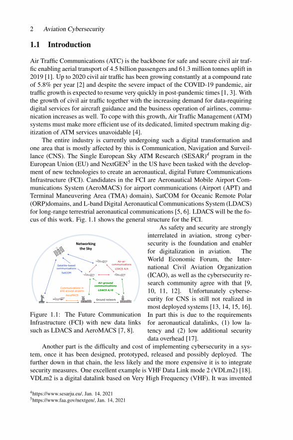
The entire industry is currently undergoing such a digital transformation andone area that is mostly affected by this is Communication, Navigation and Surveil-lance (CNS). The Single European Sky ATM Research (SESAR)4 program in theEuropean Union (EU) and NextGEN5 in the US have been tasked with the develop-ment of new technologies to create an aeronautical, digital Future CommunicationsInfrastructure (FCI). Candidates in the FCI are Aeronautical Mobile Airport Com-munications System (AeroMACS) for airport communications (Airport (APT) andTerminal Maneuvering Area (TMA) domain), SatCOM for Oceanic Remote Polar(ORP)domains, and L-band Digital Aeronautical Communications System (LDACS)for long-range terrestrial aeronautical communications [5, 6]. LDACS will be the fo-cus of this work. Fig. 1.1 shows the general structure for the FCI.
1
Networking the Sky
Ground network
Air-air communications
LDACS A/A
Communications in and around airports
AeroMACS
Satellite-based communications
SatCOM
Air-ground communications
LDACS A/G
Figure 1.1: The Future CommunicationInfrastructure (FCI) with new data linkssuch as LDACS and AeroMACS [7, 8].
As safety and security are stronglyinterrelated in aviation, strong cyber-security is the foundation and enablerfor digitalization in aviation. TheWorld Economic Forum, the Inter-national Civil Aviation Organization(ICAO), as well as the cybersecurity re-search community agree with that [9,10, 11, 12]. Unfortunately cyberse-curity for CNS is still not realized inmost deployed systems [13, 14, 15, 16].In part this is due to the requirementsfor aeronautical datalinks, (1) low la-tency and (2) low additional securitydata overhead [17].
Another part is the difficulty and cost of implementing cybersecurity in a sys-tem, once it has been designed, prototyped, released and possibly deployed. Thefurther down in that chain, the less likely and the more expensive it is to integratesecurity measures. One excellent example is VHF Data Link mode 2 (VDLm2) [18].VDLm2 is a digital datalink based on Very High Frequency (VHF). It was invented
4https://www.sesarju.eu/, Jan. 14, 20215https://www.faa.gov/nextgen/, Jan. 14, 2021
“output” — 2021/6/10 — 12:41 — page 3 — #3
Cybersecurity for LDACS 3
in the 1990ies and provides a data rate of 31.5 kbps by using Differential 8 PhaseShift Keying (D8PSK), Carrier Sense Multiple Access (CSMA) in the 118 MHzto 137 MHz band [19]. Despite being around for decades, the requirement docu-ments [20, 21] or specifications [22, 19] of the datalinks VHF or VDLm2 do notfulfill any of the information security definitions of confidentiality, integrity, avail-ability, authenticity, accountability, non-repudiation or reliability defined by RFC4949 [23]. Even newer aeronautical information systems, such as Automatic Depen-dent Surveillance Broadcast (ADS-B), a Global Navigation Satellite System (GNSS)dependent surveillance technology used by aircraft to automatically broadcast theirGNSS based position, which is mandatory since 2020, is mainly known of its insecu-rity [24, 25, 13, 26, 27] by information security standards. One of the few datalinksin the aeronautical ecosystem, which has a dedicated cybersecurity architecture is theFCI candidate for airport communications, AeroMACS. The system is majorly basedon the IEEE 802.16 WiMAX standard [7], which has a security sub-layer integratedin its protocol stack. These selected examples show a clear picture: Information se-curity or cybersecurity is still scarcely integrated into aeronautical communications.
In this chapter we describe the design process, draft and the state-of-the-art ofthe cybersecurity architecture for the ground-based digital communications systemLDACS. LDACS has been designed with security in the mind, and shall introducestate-of-the-art cybersecurity to aeronautics.
In Section 1.2, we introduce LDACS, relevant technical details and previouswork on the cybersecurity of LDACS. In Section 1.3, we list requirements and ob-jectives for the cybersecurity architecture for LDACS, which we present in Section1.4. For evaluation purposes, we evaluate the cybersecurity additions in a mathe-matical model, a software simulation of LDACS and real flight trials in Section 1.5before concluding in Section 1.6.

“output” — 2021/6/10 — 12:41 — page 4 — #4
4 Aviation Cybersecurity
1.2 Background on LDACS
LDACS is a ground-based digital communications system for flight guidance andcommunications related to safety and regularity of flight [5, 6]. It has mainly beendeveloped in Europe and is currently under standardization by ICAO [28, 29].
1.2.1 System CharacteristicsLDACS has its origin in merging parts of the B-VHF [30], B-AMC [31, 32], TIA-902 (P34) [33], and WiMAX IEEE 802.16e technologies [34]. In 2007 the spectrumfor LDACS was allocated at the World Radio Conference (WRC), which is shown inpicture 1.2.
LDACS
A/G RL
LDACS
A/G FL
JTIDS JTIDS JTIDS (MIDS)
DME/TAC DME/TACANDME/TACAN
f/MHz
GSMGalileo/GPS
DME (1157-1213)
960
SSR
SSR
11641150978 1025 1035 1085 1095
UA
T
964 1010 1110 1156
Figure 1.2: Frequency assignment forLDACS at WRC 2007, next to DME
It was decided to allocate thespectrum next to Distance MeasuringEquipment (DME), resulting in an in-lay approach between the DME chan-nels for LDACS as illustrated in Figure1.3.
Furthermore, LDACS uses 4Gtechnology to remain highly flexibleand scalable and efficient in coding,supporting adaptive coding and modulation. Additionally, it applies Frequency Di-vision Duplexing (FDD) because of the limited bandwidth available with the inlayapproach. Besides all these, LDACS supports seamless handovers, data and voicetransmissions, Quality of Service (QoS), has a navigation and surveillance exten-sion, and an Air-to-Air (A2A) link is currently being developed.
1.2.2 Communication Functionality
22 Chapter 2. Fundamentals of OFDM
FECModu-
lationFraming
OFDM
modu-
lation
Figure 2.5. Block diagram of OFDM transmitter model.
DME
Frequency
Figure 2.6. LDACS1 inlay deployment principle between two adjacent DME channels.
and the synchronization symbols are arranged into frames. The OFDM modulation
block comprises the steps summarized in the upper branch of Fig. 2.1.
2.3.2 Aspects of Inlay Approach
The inlay approach poses additional constraints on the design of OFDM systems.
In particular, the inlay system, i.e., the secondary system, has to be designed to
guarantee that the deleterious influence on primary systems is kept at an acceptable
level. On the other hand, the secondary OFDM system has to be able to work
properly, if exposed to interference from the primary system. How this can be
assured is explained in the following by analyzing the design of LDACS1.
Most parts of the aeronautical L-band are occupied by the DME system. It
works on a 1 MHz channel grid with a Gaussian shaped spectrum on each chan-
nel. Detailed DME signal characteristics are given in Section 3.3. In the LDACS1
inlay approach, the resulting gaps between adjacent DME channels are utilized by
LDACS1 channels with Beff ≈ 498 kHz. This approach implies that LDACS1 uses
also a 1 MHz channel grid, which is shifted by 0.5 MHz with respect to the DME
grid. The LDACS1 inlay deployment approach is depicted in Fig. 2.6.
PowerLDACS
Figure 1.3: Inlay approach for LDACS inbetween the DME bursts
LDACS was especially designed forATC and ATM applications like Con-troller–Pilot Data Link Communica-tions (CPDLC), Automatic DependentSurveillance-Contract (ADS-C), full4D trajectories exchange and real-timeweather information such as the Graph-ical Weather Service (WXGRAPH). Itis envisioned that Ground Based Aug-mentation System (GBAS) functional-ity will be also be provided via LDACSin the future as well [35, 36]. Theunderlying enabler for all those ap-plications are the main LDACS pa-rameters listed in Table 1.1. Thus,LDACS covers current Air Traffic Ser-vices (ATS), Aeronautical Operational

“output” — 2021/6/10 — 12:41 — page 5 — #5
Cybersecurity for LDACS 5
Control (AOC) data and also future applications, enables new concepts (e.g., sector-less ATM) and has at least an order of magnitude more net capacity than the currentlyused terrestrial links like the VDLm2 system [29].
Table 1.1: Main parameters for LDACS
Number of sub carri-ers
64 (50 used)
Bandwidth 625 / 488 kHzSubcarrier spacing 9.765625 kHzOFDM symbol dura-tion
102.4 µ
Guard interval (4.8 + 12.8) µ
Net data rate 470 kbits - 2.82Mbit/s
The latest extension ofLDACS communications capa-bilities – A/A communication– is researched in the Ger-man national project IntAir-Net [6]. The goal is toestablish direct A/A commu-nications between aircraft incommunication range allowinginfrastructure-less aeronauticalnetwork for ad-hoc networksbetween aircraft. However, thisresearch is only at an earlystage, thus we will focus solelyon the LDACS A/G link.
1.2.3 LDACS Network EntitiesFig. 1.4 depicts involved components and communication links.
GSn
...GS1
ATN
LDACSnetwork
ATS and AOC end systems
GSC
FL
RL
FL
RL
...
...
ATN = Air Traffic NetworkAOC = Aeronautical Operational ControlATS = Air Traffic ServicesAS = Aircraft StationGS = Ground StationGSC = Ground Station ControllerRL = Reverse Link FL = Forward Link
Figure 1.4: Network architecture of LDACS [37]
Up to 512 Aircraft Station (AS) communicate to an LDACS Ground Station(GS) in the Reverse Link (RL). GS communicate to AS in the Foward Link (FL). GSsare controlled by a Ground Station Controller (GSC). The GSC connects the LDACSsub-network to the global Aeronautical Telecommunications Network (ATN) to whichthe corresponding Air Traffic Services (ATS) and Aeronautical Operational Control(AOC) end systems are attached.

“output” — 2021/6/10 — 12:41 — page 6 — #6
6 Aviation Cybersecurity
1.2.4 LDACS Protocol StackFor AS and GS, we can identify different layers and entities in the LDACS proto-col stack namely Physical Layer (PHY), Medium Access Layer (MAC), Data LinkService (DLS), LDACS Management Entity (LME), Voice Interface (VI) and Sub-Network Protocol (SNP) and for the GSC, we identify the LME, as illustrated infigure 1.5.
DLSVI
MAC
SNP
AVI
DLS_CoS_5
...
DLS_CoS_0
A0
DLS_CoS_6
VCH
PHY
LME
DLSVI
MAC
SNP
DLS_CoS_5
...
DLS_CoS_0
VCH
PHY
LME
AS GS
R1
ANI
A1
VU
CTRL
EG2
DLS_CoS_6
AC-R
G1/G2
DCCH/CCCHDCCH/CCCH
CTRL
GSC
LME
SCTP
DLS_CoS_7
DC/CC
DLS_CoS_7
DC/CC
Radio
Link
Functions
Sub-Net
Functions
Radio
Link
Functions
Sub-Net
Functions
Sub-Net
Functions
Slot
Logical channel
Class of service
DCH DCH
DATA DATA
Figure 1.5: The LDACS sublayer is embedded in the FCI (IPv6, voice and controltraffic) and consists of Physical layer (PHY), Medium Access Layer (MAC), DataLink Service layer (DLS) and Voice Interface (VI), both located in the logical linkcontrol sublayer and finally the Sub-Network Protocol layer (SNP). The LDACSManagement Entity (LME) serves as a cross layer entity between MAC, DLS andSNP layer and is the single LDACS relevant entity in the GSC. Voice data is trans-mitted to higher layers via the Airborne Voice Interface (AVI) on AS side and VoiceUnit (VU) on GS side. Data is passed to higher layers via the Airborne NetworkInterface (ANI) in the AS and via the Access-Router (AC-R) in the GS.
The physical layer provides the means to transfer data over the radio channel(R1 interface). The LDACS ground-station supports bidirectional links to multipleaircraft under its control. The forward link direction (ground-to-air) and the reverselink direction (air-to-ground) are separated by FDD. Forward link and reverse linkuse a 500 kHz channel each. The ground-station transmits a continuous stream ofOrthogonal Frequency-Division Multiplexing (OFDM) symbols on the forward link.In the reverse link different aircraft are separated in time and frequency using a com-bination of Orthogonal Frequency-Division Multiple Access (OFDMA) and TimeDivision Multiple Access (TDMA). Aircraft thus transmit discontinuously on thereverse link with radio bursts sent in precisely defined transmission opportunitiesallocated by the ground-station [17].
The data-link layer provides the necessary protocols to facilitate concurrent andreliable data transfer for multiple users. The LDACS data link layer is organizedin two sub-layers: The MAC sub-layer and the Logical Link Control (LLC) sub-layer. The MAC sub-layer manages the organization of transmission opportunities inslots of time and frequency. The logical link control sub-layer provides reliable andacknowledged point-to-point logical channels between the aircraft and the ground-station using an automatic repeat request protocol.

“output” — 2021/6/10 — 12:41 — page 7 — #7
Cybersecurity for LDACS 7
Within the LDACS data link layer two entities are of special interest to us: TheLDACS Management Entity (LME) and the Sub-Network Protocol (SNP).
The main task of the LME is to perform configuration, resource managementand mobility management of LDACS. The mobility management service in the LMEprovides support for registration and de-registration (cell entry and cell exit of air-craft), scanning channels of neighboring cells and handover between cells. It alsomanages the addressing of aircraft within cells. The resource management serviceis responsible for link maintenance (power, frequency and time adjustments). InFig. 1.5, we see that that these functionalities are provided from within the LME viathe ”Radio Link Function”, while user data and communications to the SNP is man-aged via the ”Sub-Net Functions”. The SNP glues the LDACS network together andworks as a connector to the network layer. It provides end-to-end user plane and con-trol connectivity between the aircraft, ground-station and ground-station controllerwithin the LDACS sub-network.
1.2.5 Interfaces, Data Flow and Logical ChannelsLDACS internal control data is exchanged between AS and GS over the radio link(R1) and up within the protocol stacks via Common Control (CC) and DedicatedControl (DC) slots between PHY and MAC, Common Control Channel (CCCH)and Dedicated Control Channel (DCCH) logical control channels between MAC andLME. Thus all critical LDACS control functions are handled by the LME.
VI
DLS
LME
MAC
VIDCH
DCH
DLS
RACH
BCCH LME
MACDCCH
Voice
Data
Control
Voice
Data
Control
Aircraft Ground-Station
Hig
her la
yers
User Plane
Control Plane
Hig
her la
yers
DCCHCCCH
CCCH
CCCH
DCCH
Sub-
Netw
ork S
ub -
Netw
ork
Figure 1.6: Overview of LDACS logicalchannels for user data (DCH) and controldata (BCCH, RACH, CCCH, DCCH) [29]
User data is depicted in black inFig. 1.5 and travels from ground basedAeronautical Network Service Provider(ANSP) or airline servers via the AC-R over the G1/G2 link into the SNP.The DLS offers different Classes ofService (CoS), depending on the pri-ority of the user packet and via these(DLS CoS 0...5) into the DLS. Be-tween DLS and MAC, the Data Chan-nel (DCH) logical channels transportsuser data to the lower layer and via theDATA interface on slot level, user datais handed down from the MAC to PHY layer. Between AS and GS, user data istransmitted then via the radio link (R1), before it is received and handed up betweenthe different protocol layers in the AS, before being handed up to the ANI via theA1 interface. In Fig. 1.6, we see the corresponding control channels, with a deeperdescription of user (DCH) and control channels (RACH, BCCH, CCCH, DCCH)following below:
FL Data Channel (DCH) As the FL channel is held in continuous OFDM trans-mission, dedicated for the deliverance of user data, the GS locally allocates FLchannel resources (i.e. FL PHY-SDUs) within slots and manages the accesspriorities.

“output” — 2021/6/10 — 12:41 — page 8 — #8
8 Aviation Cybersecurity
RL Data Channel (DCH) In contrast to the FL DCH, RL DCH uses a bandwidthon demand scheme. Each AS has to request channel resources (RL PHY-SDUs)from the GS before they can send any user or control data in the RL data chan-nel.
Data Control Channel (DCCH) The DCCH is used in RL only, by any AS to con-vey MAC/Logical Link Layer (LLC) control messages to the GS, while eachAS has its own DCCH so that none other than this specific aircraft can send onthat channel.
Common Control Channel (CCCH) The CCCH is used in FL only and only byone GS in order to announce e.g. the MAC slot layout and to perform resourceallocation in the FL/RL to the AS. Also the GS may send control messages onthis channel.
Random Access Channel (RACH) The RACH’s purpose is predominantly for ASto make cell entry requests. Only AS may use it.
Broadcast Control Channel (BCCH) As in the name, cell configuration informa-tion and mobility management commands are sent to the AS via broadcast mes-sages. Only the GS can use it and it reaches all aircraft listening to the samebroadcast Subscriber Access Code (SAC).
1.2.6 LDACS Frame StructureIn the FL direction, each Super Frame (SF) starts with a Broadcast Channel (BC)slot, where the GS announces its existence to the AS and sends physical parametersfor link establishment. The rest of the FL SF is split into four Multi Frame (MF),each containing nine OFDM frames and each frame comprises three FL PhysicalLayer-Service Data Unit (PHY-SDU). Every FL PHY-SDU can be used to transmitFL user data or CC data, in which GS can allocate resources to an AS. Details aboutthe LDACS frame structure are depicted in Fig. 1.7.
Fre
qu
ency
Time
RL Data
variable
CC FL Data
Variable
FL Data
FL PHY-SDU
RL DC PHY-SDU
211
2
2
7
RAMulti-Frame 1
(58.32 ms)
Multi-Frame 2
(58.32 ms)
Multi-Frame 3
(58.32 ms)
Multi-Frame 4
(58.32 ms)
RA1 RA2
6.72 ms
56 OFDM
symbols
Super-Frame (240 ms)
2000 OFDM symbols
BC
BCMulti-Frame 1
(58.32 ms)
Multi-Frame 2
(58.32 ms)
Multi-Frame 3
(58.32 ms)
Multi-Frame 4
(58.32 ms)
RL
FL
58.32 ms - 486 OFDM symbols
6.48 ms
54 OFDM symbols
1 OFMD frame
3 FL PHY-PDUs
3
= 1 tile
0.72 ms
6 OFDM symbols
RL PHY-SDU
1 3
1
1602 DC 1
59
2 RA frames
3 BC frames
= 1 tile
0.72 ms
6 OFDM symbols
Figure 1.7: Frame structure of LDACS [29]
In the RL, a SF starts with a Random Access (RA) slot, where AS can requestaccess to an LDACS cell, and continues with four MFs. Each RL MF is constructedfrom 162 RL PHY-SDU equivalent to OFDMA tiles. They are used for two purposes,

“output” — 2021/6/10 — 12:41 — page 9 — #9
Cybersecurity for LDACS 9
namely (1) to transmit DC data, which are used by an AS to request the allocationfor resources allowing them to send on the RL and (2) to transmit RL user data.
1.2.7 LDACS Cell Entry ProcedureOnce a GS is securely connected to the aeronautical ground network via the GSC, itstarts sending a broadcast message, the System Identificaiton Broadcast (SIB) mes-sage, containing relevant information such as network identification, physical param-eters such as channel frequencies and more. When an AS enters the cell served by aGS, it receives the SIB and sends a CELL RQST message in reply. The CELL RQSTmessage contains a ”unique address identifying the LDACS radio” [29]. When theGS receives the CELL RQST message, a CELL RESP message is sent back to theAS, informing the AS about its System Area Code (SAC). The SAC is a local andtemporary address for the AS in the cell. After this exchange of control channel mes-sages, both communication parties are informed about LDACS specific addresses,timing, frequency, and power values and can start the user data communication.
1.2.8 LDACS Data RateData is transported in the DCH via different FL PHY-SDUs and RL PHY-SDUs ofdifferent sizes. Depending on coding and modulation, thus the channel quality, theFL PHY-SDUs sizes range from 728 to 3296 Bit, and the RL PHY-SDUs range from112 to 528 Bit. With 27 frames per MF in total and one to eight FL PHY-SDUs beingreserved on the Flight Level (FL) for the Common Control messages, this leaves 19to 26 FL PHY-SDUs per MF for data transport. The minimum amount of Bit per MFcan thus be calculated with 19∗728 = 13,832 Bit and the maximum Bit per MF with26 ∗ 3296 = 85,696 Bit. On the reverse link, the RL PHY-SDUs are separated into162 tiles. The first two tiles are sync tiles, followed by a minimum of two DC anda maximum of 32 DC tiles, which limits the minimum usable user data per MF to(162−2−32)∗112 = 14,336 Bit and allows a maximum of (162−2−2)∗528 =83,424 Bit per MF [29].
This is equivalent to a minimum data rate of 230.5 kbit/s on the FL and 238.9kbit/s on the RL, with maximum control channel use. Respectively, the maximumdata rate is 1428.3 kbit/s on the FL and 1390 kbit/s on the RL, with minimum controlchannel use.

“output” — 2021/6/10 — 12:41 — page 10 — #10
10 Aviation Cybersecurity
1.3 Security Requirements, Objectives and Functions
In previous works [38, 17, 37], several threat and risk analysis were performed result-ing in the identification of assets, threats and corresponding security requirements,objectives and functions. LDACS must follow the same protection goals as any otheraeronautical datalink within the FCI. These are [39, 11]:
Safety The system must sufficiently mitigate attacks, which contribute to safetyhazards.
Flight regularity The system must sufficiently mitigate attacks, which con-tribute to delays, diversions, or cancellations of flights.
Protection of business interests The system must sufficiently mitigate attackswhich result in financial loss, reputation damage, disclosure of sensitive proprietaryinformation, or disclosure of personal information.
The next step was to identify assets and objectives: Anything that someoneplaces value upon is regarded as asset. For LDACS five assets were identified: (1)hardware, (2) software, (3) link, (4) data, and (5) services [11].
LDACS Hardware It is responsible for the execution of LDACS software, pro-viding relevant functionality (i.e., supporting any of LDACS possible CNS services).Furthermore LDACS relevant information is stored on it. LDACS hardware refersto AS, GS, and GSC but also to an Authentication, Authorization and Accounting(AAA) server, e.g., integrated within the GSC, Access Routers, the links betweenentities and the respective LDACS specific internal and shared network and routers.
LDACS Software It enables LDACS CNS capabilities. Thus, we need to makesure that a software component of the devices or sub system is not corrupt, has noerrors or other defects. Also we have to prevent wrong installation or configurationof the software components.
LDACS Radio Link All required radio links, accurate time synchronizationalong with LDACS control data and radio communications connections enablingLDACS to transmit send and receive data via that link are assets. Most importanthere is preventing unauthorized access, altered hardware, eavesdropping, jammingand spoofing. However, we will not introduce hardware protection mechanisms,such as regular quality checks, access limitations to special hardware and control ofpersonal working on that hardware, or physical layer robustness mechanisms, such asfrequency hopping, pilot symbol scrambling, but rather focus on providing protocolbased security from the MAC layer up.
LDACS Data All data, relevant for an error-free execution of LDACS servicesare an asset. These include (but are not limited to) (1) identities of communicationentities, (2) LDACS control data, (3) user data, (4) confidential data, only accessiblefor legitimate users and entities only, (5) any cryptographic material, (6) configura-tion data or (7) data relevant for navigation services.

“output” — 2021/6/10 — 12:41 — page 11 — #11
Cybersecurity for LDACS 11
LDACS Services Several services, such as system management, announcementand routing, mobility and authentication service are required for an operational base-line for LDACS. As use case, at least 21 high critical ATS user data services and 14high critical AOC data services [38, 37] were identified to be provided by LDACS.As new functions in ATS and AOC services can be introduced on a frequent basis,this work can only contribute to highlighting already existing safety relevant servicesin regard to LDACS. Examples of them are the ATC Clearance (ACL), Data LinkLogon (DLL), Flight Plan Consistency (FLIPCY), Flight Plan Data (FLTPLAN),Network Connection NETCONN or Network Keep Alive NETKEEP service.
This analysis lead to the identification of five security objectives for LDACS in[17], which were extended to nine objectives in the official LDACS Standards andRecommended Practices (SARPS) [40]. These are (1) to protect availability andcontinuity of service, to protect (2) integrity, (3) authenticity for user and controlplane messages in transit, (4) provide non-repudiation of origin, (5) confidentialityfor user plane messages in transit, (6) mutual entity authentication, (7) authorizeexplicitly permitted actions of users or entities, (8) prevent the propagation of intru-sions within LDACS domains and towards external domains and (9) protect againstservice attacks to a level consistent with the application service requirements.
With these guidelines and objectives in mind, security functions were defined in[41, 11], following the definitions from RFC 4949 [23].
Entity Authentication We need to integrate functions for mutual entity identifi-cation, authentication authorization and accounting for every participant within theLDACS sub-net, thus preventing any un-authorized access or use of LDACS.
Key Management LDACS shall include functions for secure key generation,key agreement, key derivation, key access and key destruction.
(User) Data Confidentiality We suggest using strong symmetric encryption foruser data encryption, due to low computational overhead and fast operation times.After a master key has been negotiated between each communicating party and anencryption key derived from it, incoming user messages from the air traffic networkcan be encrypted.
Data Integrity As several threat-and-risk analysis for LDACS revealed, data-in-transit integrity is one of the most important security property for wireless com-munications systems [38, 17, 37], as due to the wireless nature of the communicationmedium, it is inherently easy to eavesdrop on messages, modify or delete them.
Data Origin Authentication Some data on the link, such as entity authentica-tion related data, shall include a data origin proof.
System Integrity Self-checks and checks at startup of systems/devices of LDACSshall detect manipulation or errors in behavior of the security mechanisms.
Robustness LDACS shall support functions ensuring reliability and robustnessto mitigate jamming, spoofing, interference or DoS attacks.

“output” — 2021/6/10 — 12:41 — page 12 — #12
12 Aviation Cybersecurity
Secure Logging Mechanisms for security and non-security relevant logging, to-gether with regular checks and possibly including the digital signature of the loggingdevice, ensures secure logging of actions within the LDACS radio devices.
Physical Access LDACS shall provide physical security commensurate to thedata it contains. This includes zeroing out keys and other secret data in emergencycases.

“output” — 2021/6/10 — 12:41 — page 13 — #13
Cybersecurity for LDACS 13
1.4 A comprehensive Cybersecurity Architecture for LDACS
In this chapter, we combine the inner workings of LDACS from Section 1.2 and cy-bersecurity requirements and functions from Section 1.3 together to present a com-prehensive cybersecurity architecture for LDACS.
1.4.1 Placements of Security Functionality in Protocol StackIn [17, 37, 41] suitable placement of security functionality within the LDACS proto-col stack was discussed.
We argue that placing protection mechanisms in the LME and SNP entitieswithin the protocol stack will be most efficient in securing LDACS. MAC and DLSwill also receive new tasks (e.g., measures for control channel protection). Securityendpoints for secure user data communication and primary entity authentication arethe AS and GSC, while the control data plane will be protected between GS andAS. Lastly, GSC and GS will establish a secure connection, prior to any aircraft be-ing able to successfully connecting to the LDACS network. With these measureswe can achieve user plane end-to-end security from GSC to AS, provide entity au-thentication among all parties and introduce key negotiation and derivation functionsbetween relevant parties.
1.4.2 TrustThe LDACS security concept requires all entities in an LDACS network to authen-ticate to each other to ascertain that only trusted participants can use the system. Toestablish trust within the network, there are multiple ways to achieve this:
Public Key Infrastructure (PKI)The general idea of a PKI is the attempt to solve the problem of having to trust acommunication’s partner identity claim.
Region 1CA
Region 2CA
Region 3CA
Region 4CA
Region 5CA
Region 6CA
Figure 1.8: Worldwide aeronauti-cal PKI - cross certification [7, 8]
A PKI can solve this problem via involvinga trusted third party who verifies the identitiesof the parties who wish to engage in communi-cation via issuing a digital certificate.
The most commonly used digital certifi-cates are X.509 [42] certificates, which contain(1) the issuing Certificate Authority (CA), the(2) CA digital signature, (3) version number,(4) serial number, (5) owner, (6) owner’s pub-lic key, (7) validity period, (8) certificate usageand (9) signature algorithm. As aviation op-erates worldwide, a hierarchical PKI will haveto be deployed with several sub-CAs being dis-tributed over the world.
Basically there are two proposals on how toachieve worldwide trust coverage [43]:

“output” — 2021/6/10 — 12:41 — page 14 — #14
14 Aviation Cybersecurity
Region 1CA
Region 2CA
Region 3CA
Region 4CA
Region 5CA
Region 6CA
ICAO Bridge
Figure 1.9: Worldwide aeronauti-cal PKI - ICAO trust bridge
One root CA is installed per geographicregion and then it performs cross-certificationwith distributed root-CAs of all other geo-graphic regions around the world. Subdomainscan exist within ATM organisations. Here trustemerges from the assured trustworthiness ofeach regional root CA cross-certifying otherand being cross-certified by other regional CAs.
This approach is depicted in Fig 1.8.The other idea is to have one worldwide (probably offline) root CA, hosted by
a trusted worldwide entity, such as ICAO, with several regions sub-CAs distributedaround the world. That way, the ICAO hosted root CA serves as trust bridge, asseen in Fig 1.9. However, a PKI comes with some drawbacks for digital aeronauticalcommunications:
1. Massive rollout, management, and revocation of certificates are required.2. A root of trust has to be declared and accepted by state actors worldwide po-
tentially requiring secure cross certification among all countries worldwide re-specting political situations and regulations in aviation. Thus, the infrastructuremust map to the political reality of aviation which is, that a small number of stateactors capable of securing critical infrastructure with limited trust towards theoutside. All this makes a PKI possibly not the best solution for a aeronauticaltrust framework.
With the two drawbacks mentioned PKI may be a challenging solution for anaeronautical trust framework. But keeping in mind that digital data links for civilaeronautical traffic (i.e. AeroMACS) use a PKI as their trust solution [44], it lookspromising to use PKI also for LDACS.
The advantage of this way forward is the possible alignment of the LDACS PKIconcept with the AeroMACS PKI [44], which is already realised and operational.Furthermore all entities within the FCI should remain interoperable, providing aseamless multi-link concept for aeronautical data, which makes the PKI based trustsolutions the most likely one.
Physical Unclonable Function (PUF) Challenge-Response Pair (CRP)The concept of Physical Unclonable Function (PUF) based trust lies within the prop-erty of unclonability of PUFs and thus the uniqueness of PUFs. Hence, a PUF canbe interpreted as a unique device’s fingerprint, an enabler to create a unique set ofCR pairs and a strong random number generator. With a secure database on groundwhere Challenge Response Pairs (CRP) are stored (and possibly unique per authen-tication round) a MAKE scheme can be established and trust incorporated into thesystem based on the trust placed unto the first transmission of CRP and secrecy ofCRP. However, the PUFs would have to be installed within the radio hardware duringa secure manufacturing process.

“output” — 2021/6/10 — 12:41 — page 15 — #15
Cybersecurity for LDACS 15
1.4.3 Mutual Authentication and Key Exchange (MAKE)Depending on the method how trust is incorporated into the system there are differ-ent approaches for Mutual Authentication and Key Exchange (MAKE) procedures.Overall all procedures need to fulfill the following three objectives:
Mutual Authentication: Both parties can be sure of the identity of the otherand that both actually participated in this interaction.
Secure Key Agreement: Both parties have established a shared session key,which means both parties know this key and know that they can use it for a securecommunication with the other party for the duration of this session. The key musthave never been used before in a session and only the two parties can know it.
Perfect Forward Secrecy: The established session key remains secret, evenwhen the private signing keys of the involved parties have been compromised afterthis session.
1.4.3.1 Station-to-Station (STS)-MAKEThe origin of LDACS mutual authentication and key exchange protocol, first men-tioned in [41], is a variation of the STS protocol [45]. Since the publication of [41],we investigated different STS variants and protocol 5.25 ”Modified STS protocol”in [45] proves to be more secure and concise than that mentioned in [41]. It pre-vents the possibility of a Man-in-the-Middle attack during the exchange of the keymaterial by signing the respective material with the help of exchanged or pre-storedpublic key certificates of the respective communication partner. However, in order toensure trust in public keys from the respective communication partner, a PKI is re-quired [41]. With a PKI and certificates in place, the modified STS protocol becomesa good candidate for mutual authentication and key agreement for LDACS.
STS-MAKE Protocol RunThe LDACS STS-MAKE protocol is illustrated in figure 1.10 and discussed in detailbelow. The protocol has 5 steps:
Step 1 – Start of STS: After cell entry is done, and the DCH of LDACS is openfor authentication purposes, the GSC chooses a secret x and calculates its Diffie-Hellman public key tGSC = gx.
Step 2 – Server Hello Key Exchange: The GSC sends the ServerHelloKeyEx-change message to the AS. The AS chooses a secret y and calculates its Diffie-Hellman public key tAS. It then calculates the static Diffie-Hellman shared keySAS,GSC = (gx)y mod p and the shared session key KAS,GSC = KDF(SAS,GSC) viaa predefined Key Derivation Function (KDF) and creates its own signatureSigAS(tAS, tGSC, IDAS, IDGSC).
Step 3 – Client Hello Key Exchange: The AS sends now its Diffie-Hellmanpublic key tAS and its signature to the GSC in the ClientHelloKeyExchange message.The GSC verifies the AS signature SigAS(tAS, tGSC, IDAS, IDGSC). If that verificationpasses, at this point the AS is authenticated to the GSC. The GSC proceeds to gen-erate SAS,GSC = (gy)y mod p and KAS,GSC = KDF(SAS,GSC) via a predefined KDF.

“output” — 2021/6/10 — 12:41 — page 16 — #16
16 Aviation Cybersecurity
Ground Station Controller (GSC) Ground Station (GS) Aircraft Station (AS)Has: IDAS, IDGS, GSC certificate: Cert(GSC), Has: IDAS, IDGS, AS certificate: Cert(AS),
Public AS key: PubKeyAS Public GSC key: PubKeyGSC
Agreed upon: g, KDF, Signature scheme: Sigparty(data), Agreed upon: g, KDF, Signature scheme: Sigparty(data),
Symmetric encryption scheme: {data}key Symmetric encryption scheme: {data}key
. . . . . . . . . . . . . . . . . . . . . . . . . . . . . . . . . . . . . . . . . . . . . . . . . . . . . . . DCH open for authentication . . . . . . . . . . . . . . . . . . . . . . . . . . . . . . . . . . . . . . . . . . . . . . . . . . . . . . .
Step 1 :Start STS
Choose secret x
Calculate tGSC = gx mod p
Step 2 :ServerHelloKeyExchange
|tGSC|
ForwardServerHelloKeyExchange
Choose secret y
Calculate tAS = gy mod p
Calculate SAS,GSC with y and tGSC = gx
SAS,GSC = (gx)y mod p
Generate KAS,GSC = KDF(SAS,GSC)
Build SigAS(tAS, tGSC, IDAS, IDGSC)
Step 3 :ClientHelloKeyExchange
|tAS|SigAS(tAS, tGSC, IDAS, IDGSC)|
ForwardClientHelloKeyExchange
Verify SigAS(tAS, tGSC, IDAS, IDGSC)
. . . . . . . . . . . . . . . . . . . . . . . . . . . . . . . . . . . . . . . . . . . . . . . . . . . . . . . . . AS authenticated to GSC . . . . . . . . . . . . . . . . . . . . . . . . . . . . . . . . . . . . . . . . . . . . . . . . . . . . . . . . .
If correct: Finish STS
Calculate SAS,GSC with x and tAS = gy
SAS,GSC = (gy)x mod p
Generate KAS,GSC = KDF(SAS,GSC), NGSC
Build SigGSC(NGSC, tGSC, tAS, IDGSC, IDAS)
Step 4 :ServerKeyExchangeFinished
|NGSC|SigGSC(NGSC, tGSC, tAS, IDGSC, IDAS)|
ForwardServerKeyExchangeFinished
Verify SigGSC(NGSC, tGSC, tAS, IDGSC, IDAS)
. . . . . . . . . . . . . . . . . . . . . . GSC authenticated to AS→ AS and GSC mutually authenticated and sharing a master secret KAS,GSC . . . . . . . . . . . . . . . . . . . . . .
Step 5 : Encrypt NGSC: {NGSC}KAS,GSC
ClientKeyExchangeFinished
{NGSC}KAS,GSC
ForwardClientKeyExchangeFinished
Decrypt NGSC: {NGSC}KAS,GSC
Verify NGSC
. . . . . . . . . . . . . . . . . . . . . . . . . . . . . Key confirmation done, Secure communication AS-GSC with KAS,GSC can commence . . . . . . . . . . . . . . . . . . . . . . . . . . . . .
Figure 1.10: LDACS STS-MAKE Protocol [46]

“output” — 2021/6/10 — 12:41 — page 17 — #17
Cybersecurity for LDACS 17
Now both parties have a shared session key KAS,GSC. It then builds another signaturetag SigGSC(NGSC, tGSC, tAS, IDGSC, IDAS).
Step 4 – Server Key Exchange Finished: The GSC sends its nonce NGSC andsignature SigGSC(NGSC, tGSC, tAS, IDGSC, IDAS) in the ServerKeyExchangeFinished mes-sage to the AS. There the AS verifies the GSC signatureSigGSC(NGSC, tGSC, tAS, IDGSC, IDAS). If that verification passes, at this point the GSCis authenticated to the AS.
Step 5 – Client Key Exchange Finished: To attain key confirmation, the ASencrypts the nonce NGSC, {NGSC}KAS,GSC and sends that in the ClientKeyExchangeFin-ished message to the GSC. At the GSC, the NGSC nonce is decrypted and verified. Ifthat verification step is successful, key confirmation of the key KAS,GSC is achieved.
Choice of Diffie-Hellman Key Exchange (DHKE) Type and Message SizesCurrently, three different DHKE approaches are considered for the STS-MAKE pro-cedure: Classic, ephemeral DHKE, Elliptic Curve Diffie-Hellmann (ECDH) and Su-persingular Isogeny Diffie–Hellman (SIDH). The original DHKE was first publishedin 1976 and is based on the discrete logarithm or Diffie-Hellman problem [47]. Givena cyclic group G of prime order n, a generator g of G and elements gx,gy ∈ G, findgxy. Due to the possibility of Man-in-the-Middle attacks [48], authenticated DHKEschemes (e.g., STS, Internet Key Exchange (IKEv2) and IKE version 2 (IKEv2)protocols [45] were invented.
Elliptic curve cryptography [49] enabled smaller key sizes, resulting in the theECDH protocol [50]. Based on the conjectured difficulty of finding isogenies be-tween supersingular elliptic curves [51], SIDH finally represents a post-quantumrobust version of the DHKE [52, 53].
We define data sizes for the authentication and key agreement messages here forthe STS for LDACS protocol. For signatures lengths, we assume a total length of64 Byte for a message signature, produced by current signature procedures such asEdDSA-Ed25519 [54] or even post-quantum procedures such as rainbow [55].
All messages have a header consisting of TY PE, ID, UA and PRIO fields.TY PE is a 4 Bit long field and clarifies the message type, ID is 12 Bit long anddenotes the ID of that message, UA is the 28 Bit long Unique Address field, con-taining the LDACS specific addresses of AS and GS and finally the 4 Bit long PRIOfield signifies the priority this particular message has. We collect all these fieldsinto the header resulting in a 48 Bit length. A nonce N is of length 96 Bit. tGSCand tAS are the Diffie-Hellman public keys of the respective entities and have dif-ferent sizes, depending on the choice of the Diffie-Hellman procedure. The sizesfor the Diffie-Hellman public key of the GSC tGSC are: {DHKE = 3072|ECDH =256|SIDH = 2624}. The sizes for the Diffie-Hellman public key of the AS tAS are:{DHKE = 3072|ECDH = 256|SIDH = 2640}.
The ServerHelloKeyExchange message, responsible to initiate the STS protocolbetween AS and GSC consists of the header and the Diffie-Hellman public key ofthe GSC tGSC. Depending on the size of the public keys, the sizes for the Server-HelloKeyExchange are {3120,304,2672} Bit. The key exchange message AS toGSC is denoted as ClientHelloKeyExchange and consists of the header, the Diffie-

“output” — 2021/6/10 — 12:41 — page 18 — #18
18 Aviation Cybersecurity
Hellman public key of the AS tAS and an AS signature SigAS. Depending on thesize of the Diffie-Hellman public keys, the sizes for ClientHelloKeyExchange are{3632,816,3200} Bit.
Table 1.2: Message sizes for STS-MAKE in bit
Message STS-DHKE STS-ECDH STS-SIDHStep 2 3120 304 2672Step 3 3632 816 3200Step 4 656 656 656Step 5 144 144 144Total 7552 1920 6672
The ServerKey Ex-changeFinished consistsof the header, a nonceNGSC, and a GSC sig-nature SigGSC, totallingin 652 Bit. Finallythe ClientKeyExchange-Finished finishes the pro-tocol and simply con-tains a header and theencrypted nonce NGSC,
resulting in 144 Bit. Overall this leads to a total amount of authentication bits shownin Table 1.2.
Please note, the STS-MAKE for LDACS was proven to fulfill the three objec-tives for LDACS MAKE protocols, mentioned at the beginning of the chapter, usingthe model checker Tamarin [56].
1.4.3.2 Physical Unclonable Function based Mutual Authenticationand Key Exchange (PMAKE)
As mentioned in Section 1.4.2, due to several reasons, PKI based MAKE protocolsmight hold several disadvantages due to the political reality in aviation, that is, asmall number of dominant state actors are capable of securing critical infrastructureand have limited trust towards others.
To address this problem, we proposed the use PUFs within LDACS radios togenerate device unique CRPs, used in PMAKE for mutual authentication. PUFs usedevice unique random patterns, which are introduced in the manufacturing processto differentiate chips and make them uniquely identifiable. In other words, a PUFcan be interpreted as a unique device’s fingerprint, an enabler to create a unique setof cr pairs and a strong random number generator.
PMAKE Protocol RunInstead of the establishment of a PKI, (1) very mobile node (aircraft) has to beequipped with a PUF during the construction process of the specific LDACS radiodevice and (2) an initial CRP has to be exchanged between aircraft and ground basedsecure verification database in a secure environment. At the end of this initial ex-change, the secure database within the GSC securely stores the CRP <CAS0 ,RAS0 >and the AS stores <CAS0 >. The main part of the protocol is depicted in Fig. 1.11.
Step 1: The AS, upon receiving such a beacon, generates a random numberrAS and depending on the respectively chosen DHKE procedure, it calculates tAS andα = HMACRAS0
(IDAS, IDGS, tAS). It then responds with |tAS⊕CAS0 |α|IDAS|.Step 2:Once the GS receives the response to the beacon message, it appends its
ID to the message and forwards |tAS⊕CAS0 |α|IDAS|IDGS| to the GSC.

“output” — 2021/6/10 — 12:41 — page 19 — #19
Cybersecurity for LDACS 19
Table 1.3 Notations used in the PMAKE scheme
Notation Definitionmsg1 ⊕ msg2 XOR operation on msg1 with msg2msg1 | msg2 Concatenation operation on msg1 with msg2PUFA Physical Unclonable Function of entity AHMACK(msg) Hash-based Message Authentication Code
with key K and input data msgHKDF(K) HMAC Key Derivation Function (HKDF)
with input KCAi i-th Challenge for PUF from entity ARAi i-th Response from PUF from entity AIDA Identifier of entity ArA Random integers of entity A
”Ephemeral private key”tA Ephemeral public key of entity Ag Public Diffie-Hellman parametersSAS,GSC Static Diffie-Hellman key shared between
AS and GSCKAS,GSC Session key for AS-GSC communications{msg}K Symmetric encryption of data msg with key KNA Nonce of entitiy A
Step 3: With the help of the previously stored tuple < CAS0 ,RAS0 >, the GSCcan compute the Diffie-Hellman public key of the AS tAS = tAS⊕CAS0 ⊕CAS0 andα ′ = HMACRAS0
(IDAS, IDGS, tAS). It then checks whether α ′ == α match. If that isthe case, the AS has authenticated to the GSC. Then the GSC generates a randomnumber rGSC of its own and again in dependence on the previously agreed DHKEprocedure, calculates tGSC. Now the shared AS-GSC key SAS,GSC can be calculatedvia the secret of the GSC rGSC and the Diffie-Hellman public key of the AS tAS. Withthat, the GSC calculates the session key KAS,GSC via the HKDF and SAS,GSC. Finallya new challenge CAS1 is chosen by the GSC and two new MAC tags are calculated.β is used to conceal CAS1 , while γ serves as authenticity proof about the GSC for theAS. It finally sends |β ⊕CAS1 |tGSC⊕ tAS|γ|IDGSC| to the GS.
Step 4: The GS forwards that message to the AS.Step 5: First the AS calculates the Diffie-Hellman public key of the GSC via
tGSC = tGSC⊕ tAS⊕ tAS. To be able to decipher CAS1 , β ′ is calculated by the AS byreconstructing RAS0 and using previously established values tGSC, tAS, IDGSC, IDGS,IDAS. As CAS1 = β ⊕CAS1⊕β ′ the AS successfully received the new challenge CAS1 .It then calculates its own value for γ ′ = HMACRAS0
(CAS1) and compares γ ′ = γ . Ifthey match, the GSC has authenticated to the AS. Furthermore the verifiable integrityand return of tAS proves to the AS, that the GSC actually participated in the protocol.Now the AS calculates the shared key SAS,GSC with rAS and tGSC and derives thesession key KAS,GSC = HKDF(SAS,GSC). Via the AS PUF a new response RAS1 is

“output” — 2021/6/10 — 12:41 — page 20 — #20
20 Aviation Cybersecurity
Ground Station Controller (GSC) Ground Station (GS) Aircraft Station (AS)Has: IDAS, IDGS,<CAS0 ,RAS0 > Has: IDGS, IDGSC,<CAS0 >,PUFAS
Agreed upon: HMAC,HKDF,g,Symmetric encryption scheme:{data}key Agreed upon: HMAC,HKDF,g,Symmetric encryption scheme:{data}key
. . . . . . . . . . . . . . . . . . . . . . . . . . . . . . . . . . . . . . . . . . . . . . . . . . . . . . . . . . . . . . . . . . . . . DCH open for authentication . . . . . . . . . . . . . . . . . . . . . . . . . . . . . . . . . . . . . . . . . . . . . . . . . . . . . . . . . . . . . . . . . . . . .
Step 1 :
Generate: rAS, Calculate: tAS, Generate: CAS0 → PUFAS → RAS0
Calculate: α = HMACRAS0(IDAS, IDGS, tAS)
ClientHelloKeyExchange
|tAS⊕CAS0 |α|
Step 2 :ClientHelloKeyExchange
|tAS⊕CAS0 |α|
Step 3 :
Calculate: tAS = tAS⊕CAS0 ⊕CAS0
Calculate: α′ = HMACRAS0
(IDAS, IDGS, tAS)
Verify: α′ == α , If match then AS is authentic
. . . . . . . . . . . . . . . . . . . . . . . . . . . . . . . . . . . . . . . . . . . . . . . . . . . . . . . . . . . . . . . . . . . . . . AS authenticated to GSC . . . . . . . . . . . . . . . . . . . . . . . . . . . . . . . . . . . . . . . . . . . . . . . . . . . . . . . . . . . . . . . . . . . . . .
Generate: rGSC , Calculate: tGSC
Calculate shared key: SAS,GSC with rGSC and tAS
Derive session key: KAS,GSC = HKDF(SAS,GSC)
Generate: CAS1
Calculate: β = HMACRAS0(IDGSC, IDGS, IDAS, tGSC, tAS)
Calculate: γ = HMACRAS0(CAS1 )
ServerHelloKeyExchange
|β ⊕CAS1 |tGSC⊕ tAS|γ|
Step 4 :ServerHelloKeyExchange
F|β ⊕CAS1 |tGSC⊕ tAS|γ|
Step 5 :
Calculate: tGSC = tGSC⊕ tAS⊕ tAS
Calculate: β′ = HMACRAS0
(IDGSC, IDGS, IDAS, tGSC, tAS)
Calculate: CAS1 = β ⊕CAS1 ⊕β′, Calculate: γ
′ = HMACRAS0(CAS1 )
Verify: γ′ == γ , If match then GSC is authentic
Calculate shared key: SAS,GSC with rAS and tGSC
Derive session key: KAS,GSC = HKDF(SAS,GSC)
. . . . . . . . . . . . . . . . . . . . . . . . . . . . . . . . . . . . GSC authenticated to AS→ AS and GSC mutually authenticated and sharing a session key KAS,GSC . . . . . . . . . . . . . . . . . . . . . . . . . . . . . . . . . . . .
Generate: CAS1 → PUFAS → RAS1
Calculate: δ = HMACRAS1(IDAS, IDGS, IDGSC, tAS, tGSC)
Calculate: ε =CAS1 ⊕RAS1
Generate: NAS
Store: <CAS1 >, Erase from device: < RAS1 >
ClientKeyExchangeFinished
|NAS|{δ |ε}KAS,GSC |
Step 6 :ClientKeyExchangeFinished
|NAS|{δ |ε}KAS,GSC |
Step 7 :
Decrypt: {δ |ε}KAS,GSC
Calculate: RAS1 =CAS1 ⊕ ε
Calculate: δ′ = HMACRAS1
(IDAS, IDGS, IDGSC, tAS, tGSC)
Verify: δ′ == δ , If match update new CRP: <CAS1 ,RAS1 >
Encrypt: {NAS}KAS,GSC
ServerKeyExchangeFinished
|{NAS}KAS,GSC |
Step 8 :ServerKeyExchangeFinished
|{NAS}KAS,GSC |
Step 9 :Decrypt: N′AS = {NAS}KAS,GSC
Verify N′AS == NAS
. . . . . . . . . . . . . . . . . . . . . . . . . . . . . . . . . . . . . . . . . . Key confirmation done, Secure communication AS-GSC with KAS−GSC can commence . . . . . . . . . . . . . . . . . . . . . . . . . . . . . . . . . . . . . . . . . .
Figure 1.11: PMAKE protocol [57]

“output” — 2021/6/10 — 12:41 — page 21 — #21
Cybersecurity for LDACS 21
generated to the new challenge CAS1 via CAS1 → PUFAS → RAS1 . It then calculatesδ = HMACRAS1
(IDAS, IDGS, IDGSC, tAS, tGSC) that will be used by the GSC as prooffor the authenticity and correctness of the new response RAS1 . ε =CAS1⊕RAS1 is usedto conceal the response RAS1 during transport. For key confirmation purposes, the ASgenerates a nonce NAS. At this point, the AS securely stores CAS1 and erases RAS1from memory. As AS and GSC have previously agreed upon suitable encryptionalgorithms, the AS sends NAS in the clear and δ and ε encrypted with KAS,GSC backto the GSC.
Step 6: The GS forwards that message to the GSC.
Step 7: The GSC decrypts the message with the agreed upon encryption al-gorithm and key KAS,GSC. It then computes RAS1 = CAS1 ⊕ ε . It then calculatesδ ′ = HMACRAS1
(IDAS, IDGS, IDGSC, tAS, tGSC) and checks whether δ ′ == δ . If thatis the case, the GSC can be sure of the authenticity of the response RAS1 and theparticipation of AS in the protocol. It updates the current tuple for that AS to<CAS1 ,RAS1 >. It then encrypts NAS and sends it back to the AS.
Step 8: The GS forwards that message to the AS.
Step 9: Finally the AS decrypts N′AS = {NAS}KAS,GSC and compares N′AS == NAS.If they match, AS is assured that GSC also holds the shared key, key confirmationwas successful and user data communication can commence.
PMAKE Data OverheadAgain, in analogy to the previous description of message sizes for STS-MAKE, weassign amounts of bits to the different messages.
Table 1.4 Message sizes for PMAKE in bit
Message PMAKE-DHKE PMAKE-ECDH PMAKE-SIDHStep 1 3276 460 2844Step 3 3404 588 2956Step 5 400 400 400Step 7 144 144 144Total 7224 1592 6344
We assume the same sizes as before, so header = 48 Bit, all IDs = 28 Bit,nonces NAS = 96 Bit, MAC tag (c.f., α,β ,γ,δ ,ε)= 128 Bit, Diffie-Hellman publickey sizes for tGSC: {DHKE = 3072|ECDH = 256|SIDH = 2624}, Diffie-Hellmanpublic key sizes for tAS: {DHKE = 3072|ECDH = 256|SIDH = 2640}. We showall PMAKE message sizes in Table 1.4.
1.4.4 Key DerivationOne all parties within the network have successfully authenticated to each other, keyderivation is necessary to generate different keys for different purposes. For example,we need keys for user data protection and keys for control data protection.

“output” — 2021/6/10 — 12:41 — page 22 — #22
22 Aviation Cybersecurity
HKDFAs shown in Fig. 1.10 and Fig.1.11, we use the HKDF, a KDF built from Hash-based Message Authentication Codes (HMAC). It uses the ”extract-then-expand”paradigm, meaning that it consists of two main phases.
First the input keying material (here: master key/static Diffie Hellman sharedkey) is taken and a fixed-length pseudo-random key is extracted. The extract phaseis especially important, if the master key is not sufficiently uniform (e.g. the key isuniform only in a subset of the original key space). In that case, we extract a pseudorandom key from the master key by adding a salt value, which can be any fixednon-secret string chosen at random. In the process the pseudo random key becomesindistinguishable from a uniform distribution of bits. In general, HKDF can be usedwith or without salt value, both variations work, however the use of salt significantlyincrease the strength of HKDF. Salt ensures independence between different usesof the hash function, supports ”source-independent” extraction, and strengthens theanalytical results that back the HKDF design [58].
User Data Protection KeysAlso depending on the algorithm choice for securing user data on the datalink, weneed either one symmetric key (e.g., for AES-GCM [59], which allows integrity andconfidentiality protection) or two symmetric keys for integrity and confidentialityprotection.
Control Data Protection KeysAs discussed before in Section 1.2.6, securing the control plane of LDACS provesmore difficult than its user plane. The underlying problems are very small chunksof data (e.g., RL DCCH: 83 Bit) and the need that every aicraft within one LDACScell can read the entire control data plane of LDACS. Thus using individual ASspecific keys for securing the CCCH, DCCH channels is not possible. We do not putadditional cryptographic protection on the Random Access Control Channel (RACH)or bcch¸ , as if any spoofer or attacker sending information within those data links isdetected and filtered out during the MAKE procedure of LDACS. As the data onthe DCCH is mainly responsible to enable an AS to request data allocations, suchthat it can send user data and the CCCH being the logical channel, via which thoseresources are granted, integrity protection of these is most important to prevent anyattacker redistributing LDACS resources.
The only possible way to meet all these requirements, is via introducing groupkey mechanisms for LDACS. We are currently investigating and comparing the suit-ability of the Group-IKEv2 [60], Chinese Remainder Group Key (CRGK) [61], Cen-tral Authorized Key Extension (CAKE) [62] and Logical Key Hierarchy (LKH) pro-tocol [63] for LDACS. This process is ongoing work and has not concluded yet.
1.4.5 User Data SecurityAfter the MAKE procedure and with the key derivation of user keys, the user dataplane of LDACS can be secured.

“output” — 2021/6/10 — 12:41 — page 23 — #23
Cybersecurity for LDACS 23
We propose to secure LDACS SN-PDUs, thus Packet Data Uni (PDU)s on theSNP, as their size can vary from 128 to 1536 Byte [29], which makes them possiblythe largest PDUs within LDACS. This helps minimizing security data overhead, incase a Message Authentication Code (MAC) tag is attached to the SN-PDU.
Confidentiality ProtectionWe suggest using symmetric approaches for data encryption, due to low computa-tional overhead and fast operation times. We propose to establish end-to-end encryp-tion for e.g., Aeronautical Operational Control (AOC) data between GSC and AS.After extensive discussion with representatives of ATC instances, it became appar-ent, that ATS data will probably not be encrypted, as every air traffic controller op-erating in the area should be able to read that data for safety reasons. Thus, betweenlayer 3 and the LDACS sublayer, some notification of the content of the packet willbe necessary. As encryption algorithm, we recommend AES-256-GCM [59] withGalois Counter Mode (GCM) being a mode of operation on symmetric key block.It provides authenticated encryption and decryption operations and it proves robustagainst currently known quantum-computer-based algorithms [64]. The last prop-erty is important, as due to the long service life of aeronautical communications, thisrising threat might become dangerous during its life cycle.
Integrity ProtectionAll user data, sent via LDACS, requires some kind of integrity protection mecha-nism. We propose two mutually exclusive strategies:
AES-GCM Galois Counter Mode is a mode of operation for symmetric keycryptographic block ciphers (i.e., here: AES). It supports two operations: authen-ticated encryption and decryption. If only message authentication is required, thevariation Galois Message Authentication Code (GMAC) can be used. After the ap-plication of this operation mode, we are left with a ciphertext C of exactly the samelength as the plaintext P and an authentication tag T of 128 Bit length. However[65] defines tag sizes of 128, 120, 112, 104, or 96, 64 and 32 Bit length, with a clearrecommendation to use 96 Bit or more.
HMAC Here, the idea is to combine the Keyed-Hash Message AuthenticationCode (HMAC) message authentication mechanism [66] and combine it with hash-functions from the SHA-3 hash-family [67]. We propose HMAC-SHA3-128, thatway, we are left with a plaintext P and a message tag T of 128 Bit length.
1.4.6 Control Data SecurityAs described in depth in Section 1.4.4, securing the control data plane of LDACSproves to be far more complicated than its user plane. Reasons for this are far smallermessage sizes (c.f., DC: 83 Bit, CC: 728 Bit), the need, that every participant withinan LDACS cell need to be able to (1) read its contents and (2) be assured of theirauthenticity.
That way, it is clear, that we need control data integrity and not necessarilyconfidentiality. This leaves us with the problem, that a simple message tag simply

“output” — 2021/6/10 — 12:41 — page 24 — #24
24 Aviation Cybersecurity
does not fit in the small control messages. Even if we shrink the tag size to e.g.,32 Bit, radically reducing the security level, the capacity of LDACS would be alsoreduced drastically, as fewer resources could be requested and allocated, due to thereduced configuration data space left within the messages.
Securing FL control plane data is easier than its RL counterpart, as the GS cansend a continuous stream of OFDM symbols on the FL and is thus the only entityputting data on the CCCH. Assuming a group key has been negotiated within thegroup of one GS and all AS within that particular LDACS cell, that key can be usedby the GS to add a small message tag to a CC-PDU. Assuming a 64 Bit tag to besufficiently secure, this still results in a 64/728 = 8,8% overhead.
On the other direction, every AS requests resources on the DCCH, thus everyaircraft contributes DC-PDUs and every one is 83 Bit long. With that size, and giventhat only 8 Bit are currently reserved for padding [29], applying a message tag perDC-PDU is impossible.
This topic, altogether with the investigation of group key procedure for LDACSis currently ongoing and will have to be solved before the LDACS security architec-ture can be finalized.
1.4.7 Changes within the LDACS Protocol StackAt the beginning of that chapter, we discussed placement of security functionalitywithin the LDACS protocol stack. After having described the entire process of howtrust is handled, options for entity authentication and key exchange, key derivation,user data and control data protection, we want to assign all these tasks to certainentities within the LDACS protocol stack.
In Fig. 1.12, we have added security relevant states and functionality, markedin red, within the LDACS protocol stack. As said at the beginning of this chapter,LME and SNP are the two most important, security related entities. The LME han-dles the entire connection establishment and now MAKE procedure, together withkey negotiation, derivation, handover and secure logging. It is also responsible forprotecting control channel data. The SNP, after the MAKE procedure is over and ithas received the user data session key from the LME handles user data protection.
Also one important factor are the CoS of LDACS: After initial connection es-tablishment and during the MAKE procedure, the DLS and SNP only allow packetsof the highest priority (i.e., CoS=7) to pass through to the LME for authenticationpurposes. No other data packet is able to pass through, before the LME has not suc-cessfully completed the entire MAKE procedure, with session keys being deployedat LME for control data protection and SNP for user data protection.

“output” — 2021/6/10 — 12:41 — page 25 — #25
Cybersecurity for LDACS 25
DLS
D_SAPD
D_S
AP
CSNP
MAC
M_SAPC M_SAPDM_SAPB M_SAPRM_SAPI
LME
MAC_CONNECT.req
MAC_FSCAN.req
MAC_CSCAN.req
MAC_GSCAN.req
MAC_OPEN.req
MAC_HO.req
DLS_DATA.reqDLS_DATA.ind
DLS_UDATA.reqDLS_UDATA.ind
MAC_DCH.indMAC_DCH.req
DLS_OPEN.reqDLS_CLOSE.req
L_SAPVL_SAPC
SN_SAPD
SN
_S
AP
C/D
SN_DATA.reqSN_DATA.ind
SN_UDATA.reqSN_UDATA.indSN_CONF.req
Network Management Network Layer
States:CLOSEAUTHOPEN
AUTH: Allow CoS = 7 OPEN: Allow CoS < 7
OPENAUTHCLOSEStates: AUTH:
ForwardDATAto LME
OPEN:(optional)- En-/Decrypt SN_PDU- Apply/Verify SN_PDU authentication tag
CSCANNINGFSCANNINGStates:
CONNECTINGOPEN
AUTH
CSCANNINGFSCANNINGStates:
CONNECTINGAUTHOPEN
AUTH:- (Opt.) Certificate handling- (Opt.) PUF access- MAKE procedure - Entity authentication - Key negotiation - Key derivation - Key handling (e.g., handover of user data session key to SNP) - Secure logging
OPEN:- Control data protection- Secure logging
MAC_BCCH.reqMAC_BCCH.ind
MAC_RACH.reqMAC_RACH.ind
MAC_CCCH.reqMAC_CCCH.ind MAC_DCCH.reqMAC_DCCH.ind
Figure 1.12: Security related changes within the LDACS protocol stack

“output” — 2021/6/10 — 12:41 — page 26 — #26
26 Aviation Cybersecurity
1.5 Evaluation of the LDACS Cybersecurity Architecture
The cybersecurity measures of LDACS were evaluated in [11, 68, 46, 57]. Here wewant to present evaluations (1) in a theoretical model for LDACS security data andlatency overhead, (2) modelled in an event based simulation framework Frameworkfor Aeronautical Communications and Traffic Simulations 2 (FACTS) and (3) actualflight trials.
1.5.1 Theoretical Model for LDACS Security Latency OverheadIn 2015, Graupl et al. [69] presented a full methodology on how to emulate latenciesfor user data in the forward and reverse link of LDACS depending on the Bit ErrorRate (BER) and message size.
Taking re-transmissions into account, the FL latency can be calculated with
LFL(t) = mFL(t)+(1+δRX (1+n))×dMF (1.1)
and the RL latency with
LRL(t) = mRL(t)+(2+δRX (N +3))×dMF . (1.2)
Table 1.5 Parameter values for latency timing for the LDACS MAC protocol [46]
Forward Link Model (Eq. 1.1) Reverse Link Model (Eq. 1.2)Parameters Values Parameters ValuesdMF 60ms dMF 60msmFL(t) Time until start mRL(t) Average time until start
of next FL MF: of next MAC cycle:Every 1 to 60ms #AS/32×dMF +waitmodelled by U(1,60) wait modelled by U(1,60)
n Average amount of N Average amount of MFsMF after transmission after transmissionuntil next DC slot is until next DC slotscheduled for AS is scheduled for AS:in MAC-cycle: N = (#AS/32−3)n = #AS/32 mod #AS/32
BER 10−6,10−5
P P({no error in packet}) = (1−BER)l
P({error in packet}) = 1− ((1−BER)l)
In Equation 1.1, we use mFL(t) to classify the time until the start of the nextCC frame, δRX ∈ {0,1} to indicate a re-transmission, dMF denotes the length of aMF and n is derived from the length of the reverse link medium access cycle fromforward link perspective.
In Equation 1.2, we use mRL(t) to denote the time until the start of next DC slot,δRX ∈ {0,1} to indicate a re-transmission, dMF denotes the length of a MF and N isderived from the length of the reverse link medium access cycle from reverse linkperspective.

“output” — 2021/6/10 — 12:41 — page 27 — #27
Cybersecurity for LDACS 27
We model δRX ∈ {0,1} as stochastic process, based on the packet error rate.Given a BER, we can calculate the packet error rate based on the length of a packet l:P({no error in packet}) = (1−BER)l . Thus the opposite event, that a packet indeedcontains an error is: P({error in packet}) = 1− ((1−BER)l). These two probabilitydecide the value of δRX , whether a re-transmission is necessary and, thus, an errorappeared in the packet, or not.
For more details on the model, please refer to [69] and [46].With these equations, we calculate LDACS authentication latencies based on the
amount of AS within an LDACS cell. We see these results in Fig. 1.13.
0 100 200 300 400 500Amount of AS in LDACS cell
500
1000
1500
2000
2500
Late
ncy
(ms)
Minimum MAKE latency valuesMean MAKE latency values95%-Percentile MAKE latency valuesMaximum MAKE latency values
(a) Authentication latency at BER = 0
0 100 200 300 400 500Amount of AS in LDACS cell
500
750
1000
1250
1500
1750
2000
2250
2500
Late
ncy
(ms)
Mean latency DHKE95%-Percentile latency DHKEMean latency ECDH95%-Percentile latency ECDHMean latency SIDH95%-Percentile latency SIDH
(b) Authentication latency at BER = 10−5
Figure 1.13: Authentication baseline latency at BER = 0 vs. authentication latencyat worst case scenario of BER = 10−5.
Please note that due to the similar message sizes, PMAKE and STS-MAKEhave almost equal authentication latencies. Both authentication procedures finishquicker with smaller message sizes at higher BER, thus ECDH finishes faster thanSIDH, which in turn finishes faster than DHKE. The requirements document DO-350A imposes a RCT PCSP = 10s threshold for RCP 130/A1 message types [70],meaning that all authentication and connection establishment must be completedbelow the 10s threshold [29]. As we clearly see in Fig. 1.13, we always remainbelow this threshold, even when an LDACS cell is full.
1.5.2 Model within FACTS2 Simulation FrameworkAnother important way of evaluating changes within the LDACS protocol is rapidprototyping with software based simulations. FACTS [71] is a simulation frameworkbased on modern, service-oriented software architecture: Simulation services orga-nized in a parallelized toolchain of loosely coupled software services split by theseparation of concerns. It allows for the simulation of infrastructure, generation ofaeronautical data traffic, simulation of flight patterns or parsing of real-world flightpatterns, simulation of arbitrary aeronautical data links and protocols and more. Ev-ery tool is tasked with one task (e.g., simulating the LDACS datalink) and multipletools can be piped together, using Unix pipes on the command line. In Fig. 1.14, we

“output” — 2021/6/10 — 12:41 — page 28 — #28
28 Aviation Cybersecurity
see first worldwide air traffic movement, then FACTS simulates realistic air trafficdata, simulates LDACS as underlying datalink and outputs a report on the perfor-mance of the datalink.
(a) Graphical output of worldwide air traffic (b) Output of LDACS measurement report
Figure 1.14: Two important capabilities of FACTS: (1) visual output of air trafficmovement (2) measurement reports on the performance of tested datalinks [71]
In [68], we used FACTS to demonstrate a proof of concept of the user datasecurity architectural concept of LDACS. Results proved, that the implementationconcept with the ”auth” state within protocol entities and different classes of ser-vice, with the highest priority class reserved for authentication purposes, works asintended. Thus authentication, key exchange, derivation and handover were per-formed and SN-PDUs could be secured via the AES-256-GCM algorithm and thenegotiated, shared session keys as described in Section 1.4.7.
1.5.3 Real World Demonstration of LDACS Security FeaturesLastly, during the German national project Migration towards COm/NAV capabili-ties of LDACS (MICONAV) in March/April 2019, we could demonstrate some secu-rity features of LDACS in the worldwide first LDACS flight trials. Fig. 1.15 showsthe research aircraft used in the flight trials, a Falcon 20-E5, together with the posi-tion of the L-band antenna.
AS L-band Antenna Position
Figure 1.15: DLR’s research aircraft Falcon 20-E5 (D-CMET) [36]
In Fig.1.16a and in Fig. 1.16b, we show the LDACS GS demonstration setupand in Fig. 1.16c the AS LDACS demonstration equivalent.

“output” — 2021/6/10 — 12:41 — page 29 — #29
Cybersecurity for LDACS 29
LDACS GS HPA
LDACS GS Rx/Tx
IQ Recorder
GS Rb Clock
Ethernet Switch
LDACS Ground PC
(a) LDACS ground station
GS L-band
Antenna
Position
(b) LDACS antenna
AS Rb Clock
LDACS AS HPA
LDACS
Airbone PC
LDACS AS Tx
Ethernet Switch
(c) Airborne equipment
Figure 1.16: Overview of airborne and ground LDACS equipment [36]
With pre-installed certificates at the AS and GS, we demonstrated a key en-capsulation procedure based on the post-quantum robust public-key cryptosystemMcEliece [72]. Using this negotiated session key as a result, we encrypted any ac-tual data, such as text messages, CPDLC messages, ADS-C messages for AS po-sitioning with the aforementioned AES-256-GCM symmetric cryptosystem. Withdata gained during the actual flight, we can confirm, that the chosen MAKE proce-dure itself remained below the required RCT PCSP = 10s threshold for RCP 130/A1message types [70]. Overall we performed 19 key exchanges and observed a meankey exchange time of 508.15 ms and a 95-percentile of 513.13 ms. This matches thevalues presented in Fig. 1.13 with just one AS in an LDACS cell very well and is astrong indicator for the accuracy of the theoretical model and the FACTS simulation.
Figure 1.17: Console output during after successful key exchange. All further com-munication afterwards was secured using AES-256-GCM.
In Fig. 1.17, we see the console output of a successful key exchange and with se-cured communications channel opened, aboard the Falcon 20-E5 during MICONAV.

“output” — 2021/6/10 — 12:41 — page 30 — #30
30 Aviation Cybersecurity
1.6 Conclusion
This work presents a summary of the design of the LDACS cybersecurity concept.We introduce the FCI and the current state of cybersecurity in digital aeronauticalcommunications, which is that especially on legacy datalinks (i.e., ADS-B, VDLm2)there is no information security based on the definitions from the internet securityglossary RFC 4949. We continue with a presentation of relevant technical detailsabout LDACS and then with a threat- and risk analysis, defining security require-ments, objectives and functions. We start the section on the LDACS cybersecurityarchitecture with different trust approaches, a PKI and a PUF CRP based, then con-tinue with two MAKE procedure based on these trust solutions. We propose the useof AES-GCM for user data protection, and state out reasons, why integrity is moreimportant than confidentiality. On the security for control plane data, we are in-vestigating the use of group-key procedure, however this is still a work in progress.Finally we finish with a compete integration of the security additions within theLDACS protocol stack. In the evaluation, we show, that both MAKE proceduresfinish far below the required latency threshold and only put up to 1 kB of additionalsecurity data on the link. Also via analytical evaluation, a software event-based sim-ulation, and flight trials, we present a first proof-of-concept of LDACS cybersecurity.
Future work aims to solve the open problem of control channel security ofLDACS by investigating different group key procedures and different approacheson guaranteeing integrity of control data. Also proving the semantic correctnessand soundness of LDACS protocol security with model checkers such as Tamarin,Scyther or ProVerif is an important step in the validation of LDACS cybersecurityfeatures. Finally, further flight trials are planned for 2022, where the entire cyberse-curity concept can be validated in flight trials on more advanced LDACS prototypehardware.
All candidates within the FCI require strong cybersecurity features. We agreewith this requirement as we strongly believe, cybersecurity is the enabler in the futureautomation of civil air traffic. As LDACS is the worldwide first truly integrated CNSsystem, and thus an important part of the digitization process, this work on cyberse-curity for LDACS is an essential pillar for the final standardization and deploymentof LDACS.

“output” — 2021/6/10 — 12:41 — page 31 — #31
Abbreviations
A2A Air-to-AirAC-R Access-RouterADS-B Automatic Dependent Surveillance BroadcastADS-C Automatic Dependent Surveillance-ContractAeroMACS Aeronautical Mobile Airport Communications SystemANI Airborne Network InterfaceANSP Aeronautical Network Service ProviderAOC Aeronautical Operational ControlAPT AirportAS Aircraft StationATC Air Traffic CommunicationsATM Air Traffic ManagementATN Aeronautical Telecommunications NetworkATS Air Traffic ServicesAVI Airborne Voice Interface
BC Broadcast ChannelBER Bit Error Rate
CA Certificate AuthorityCC Common ControlCCCH Common Control ChannelCNS Communication, Navigation and SurveillanceCoS Classes of ServiceCPDLC Controller–Pilot Data Link CommunicationsCRP Challenge-Response PairCSMA Carrier Sense Multiple Access
D8PSK Differential 8 Phase Shift KeyingDC Dedicated ControlDCCH Dedicated Control ChannelDCH Data ChannelDHKE Diffie-Hellman Key ExchangeDLS Data Link ServiceDME Distance Measuring Equipment
ECDH Elliptic Curve Diffie-Hellmann

“output” — 2021/6/10 — 12:41 — page 32 — #32
32 Abbreviations
FACTS Framework for Aeronautical Communications and Traffic Simulations 2FCI Future Communications InfrastructureFDD Frequency Division DuplexingFL Flight LevelFL Foward Link
GBAS Ground Based Augmentation SystemGNSS Global Navigation Satellite SystemGS Ground StationGSC Ground Station Controller
HKDF HMAC Key Derivation FunctionHMAC Keyed-Hash Message Authentication Code
ICAO International Civil Aviation OrganizationIKEv2 Internet Key Exchange
KDF Key Derivation Function
LDACS L-band Digital Aeronautical Communications SystemLLC Logical Link ControlLME LDACS Management Entity
MAC Medium Access LayerMAKE Mutual Authentication and Key ExchangeMF Multi FrameMICONAV Migration towards COm/NAV capabilities of LDACS
OFDM Orthogonal Frequency-Division MultiplexingOFDMA Orthogonal Frequency-Division Multiple AccessORP Oceanic Remote Polar
PDU Packet Data UniPHY Physical LayerPHY-SDU Physical Layer-Service Data UnitPKI Public Key InfrastructurePMAKE Physical Unclonable Function based Mutual Authentication and Key Ex-
changePUF Physical Unclonable Function
QoS Quality of Service
RA Random AccessRACH Random Access Control ChannelRL Reverse Link

“output” — 2021/6/10 — 12:41 — page 33 — #33
REFERENCES 33
SAC System Area CodeSARPS Standards and Recommended PracticesSESAR Single European Sky ATM ResearchSF Super FrameSIB System Identificaiton BroadcastSIDH Supersingular Isogeny Diffie–HellmanSNP Sub-Network ProtocolSTS Station-to-Station
TDMA Time Division Multiple AccessTMA Terminal Maneuvering Area
VDLm2 VHF Data Link mode 2VHF Very High FrequencyVI Voice InterfaceVU Voice Unit
References
[1] IATA. Economic Performance of the Airline Industry. Interna-tional Air Transport Association (IATA); 2020. [Online]. Avail-able: https://www.iata.org/en/iata-repository/publications/economic-reports/airline-industry-economic-performance—november-2020—report/.
[2] ACI. Economic Performance of the Airline Industry. Air-ports Council International (ACI); 2019. [Online]. Available:https://store.aci.aero/product/annual-world-airport-traffic-report-2019/.
[3] Iacus SM, Natale F, Santamaria C, et al. Estimating and projecting air passen-ger traffic during the COVID-19 coronavirus outbreak and its socio-economicimpact. Safety Science. 2020 September;129:104791. Available from:http://www.sciencedirect.com/science/article/pii/S0925753520301880.
[4] Slim M, Mahmoud B, Pirovano A, et al. Aeronautical Communication Tran-sition From Analog to Digital Data: A Network Security Survey. ComputerScience Review. 2014 May;11-12:1–29.
[5] Schnell M, Epple U, Shutin D, et al. LDACS: Future Aeronautical Communi-cations for Air-Traffic Management. IEEE Communication Magazine. 2014May;52(5):104–110.
[6] Schnell M. Update on LDACS - The FCI Terrestrial Data Link. In: 19th In-tegrated Communications, Navigation and Surveillance Conference (ICNS).New York, NY, USA: IEEE; 2019. p. 1–10.
[7] Kamali B. AeroMACS: An IEEE 802.16 Standard-based Technology for theNext Generation of Air Transportation Systems. John Wiley & Sons; 2018.
[8] Graupl T, Rihacek C, Haindl B. LDACS A/G Specification. Oberpfaffen-hofen, Germany: German Aerospace Center (DLR); 2019.

“output” — 2021/6/10 — 12:41 — page 34 — #34
34 Aviation Cybersecurity: Foundations, principles, and applications
[9] Strohmeier M, Schafer M, Pinheiro R, et al. On perception and reality inwireless air traffic communication security. IEEE transactions on intelligenttransportation systems. 2016;18(6):1338–1357.
[10] Bernsmed K, Fr C, Meland PH, et al. Security requirements for SATCOMdatalink systems for future air traffic management. In: 2017 IEEE/AIAA36th Digital Avionics Systems Conference (DASC). IEEE; 2017. p. 1–10.
[11] Maurer N, Schmitt C. Towards Successful Realization of the LDACS Cy-bersecurity Architecture: An Updated Datalink Security Threat- and RiskAnalysis. In: 19th Integrated Communications, Navigation and SurveillanceConference (ICNS). New York, NY, USA: IEEE; 2019. p. 1A2/1–1A2–13.
[12] Hall A, Wingfield J, De Moura G, et al. Advancing Cyber Resilience inAviation: An Industry Analysis. World Economic Forum; 2020.
[13] Costin A, Francillon A; EURECOM. Ghost in the Air(Traffic): On Insecurityof ADS-B protocol and Practical Attacks onADS-B Devices. Black Hat USA.2012 August;p. 1–10.
[14] Strohmeier M, Lenders V, Martinovic I. On the security of the automaticdependent surveillance-broadcast protocol. IEEE Communications Surveys& Tutorials. 2014;17(2):1066–1087.
[15] Stelkens-Kobsch TH, Hasselberg A, Muhlhausen T, et al. Towards a more se-cure ATC voice communications system. In: 2015 IEEE/AIAA 34th DigitalAvionics Systems Conference (DASC). IEEE; 2015. p. 4C1–1.
[16] Harison E, Zaidenberg N. Survey of Cyber Threats in Air Traffic Control andAircraft Communications Systems. In: Cyber Security: Power and Technol-ogy. Springer; 2018. p. 199–217.
[17] Bilzhause A, Belgacem B, Mostafa M, et al. Datalink Security in theL-band Digital Aeronautical Communications System (LDACS) for AirTraffic Management. Aerospace and Electronic Systems Magazine. 2017November;32(11):22–33.
[18] ICAO. LDACS White Paper–A Roll-out Scenario. International Civil Avia-tion Organization (ICAO); 2019.
[19] ICAO. Doc 9776 - Manual on VHF Digital Link (VDL) Mode 2. In-ternational Civil Aviation Organization (ICAO); 2015. [Online]. Avail-able: http://www.icscc.org.cn/upload/file/20190102/Doc.9776-EN Manualon VHF Digital Link (VDL) Mode 2.pdf.
[20] RTCA. DO-225, VHF Air-Ground Communications System ImprovementsAlternatives Study and Selection of Proposals for Future Action. Radio Tech-nical Commission for Aeronautics (RTCA); 1994.
[21] RTCA. DO-281C - Minimum Operational Performance Standards (MOPS)for Aircraft VDL Mode 2 Physical Link and Network Layer. Radio TechnicalCommission for Aeronautics (RTCA); 2018.
[22] ICAO. Annex 10 - Aeronautical Telecommunications - Volume III - Com-munication Systems. International Civil Aviation Organization (ICAO);2007. [Online]. Available: https://store.icao.int/en/annex-10-aeronautical-telecommunications-volume-iii-communication-systems.

“output” — 2021/6/10 — 12:41 — page 35 — #35
REFERENCES 35
[23] Shirey R. Internet Security Glossary, Version 2. RFC Editor; 2007. 4949.Available from: https://www.rfc-editor.org/rfc/rfc4949.txt.
[24] Kunkel R. Village DA, editor. Air Traffic Control: Insecu-rity and ADS-B [YouTube, Date video uploaded: 16.01.2011,[Video file]]. DEFCON 28; 2011. [Online]. Available:https://www.youtube.com/watch?v=aU8NpyYf9wY [Accessed: January07, 2020].
[25] McCallie D, Butts J, Mills R. Security analysis of the ADS-B implementa-tion in the next generation air transportation system. International Journal ofCritical Infrastructure Protection. 2011;4(2):78–87.
[26] Strohmeier M, Schafer M, Lenders V, et al. Realities and challenges ofnextgen air traffic management: the case of ADS-B. IEEE CommunicationsMagazine. 2014;52(5):111–118.
[27] Wu Z, Shang T, Guo A. Security Issues in Automatic DependentSurveillance-Broadcast (ADS-B): A Survey. IEEE Access. 2020;8:122147–122167.
[28] (ICAO) ICAO. Finalization of LDACS Draft SARPs - Working Paper WP05including Appendix. Montreal, Canada: ICAO; 2018.
[29] Graupl T, Maurer N, Schmitt C. FACTS2: Framework for Aeronautical Com-munications and Traffic Simulations 2. In: Proceedings of the 16th ACMInternational Symposium on Performance Evaluation of Wireless Ad Hoc,Sensor, & Ubiquitous Networks; 2019. p. 63–66.
[30] Brandes S, Schnell M, Rokitansky CH, et al. B-VHF - Selected SimulationResults and Final Assessment. In: 25th Digital Avionics Systems Conference(DASC). New York, NY, USA: IEEE; 2006. p. 3A4/1–3A4/12.
[31] Rokitansky CH, Ehammer M, Graupl T, et al. B-AMC A System for FutureBroadband Aeronautical Multi-Carrier Communications in the L-Band. In:36th Digital Avionics Systems Conference (DASC). New York, NY, USA:IEEE; 2007. p. 4D2/1–4D2/13.
[32] Schnell M, Brandes S, Gligorevic S, et al. B-AMC - Broadband AeronauticalMulti-carrier Communications. In: 8th Integrated Communications, Naviga-tion and Surveillance Conference (ICNS). New York, NY, USA: IEEE; 2008.p. 4D2/1–4D2/13.
[33] Haindl B, Rihacek C, Sajatovic M, et al. Improvement of L-DACS1 Designby Combining B-AMC with P34 and WiMAX Technologies. In: 9th In-tegrated Communications, Navigation and Surveillance Conference (ICNS).New York, NY, USA: IEEE; 2009. p. 1–8.
[34] Ehammer M, Graupl T. AeroMACS - An Airport Communications System.In: 30th Digital Avionics Systems Conference (DASC). New York, NY, USA:IEEE; 2011. p. 4C1/1–4C1/16.
[35] Felux M, Graupl T, Maurer N, et al. Transmitting GBAS messages viaLDACS. In: 2018 IEEE/AIAA 37th Digital Avionics Systems Conference(DASC). IEEE; 2018. p. 1–7.
[36] Maurer N, Graupl T, Bellido-Manganell MA, et al. Flight Trial Demon-stration of Secure GBAS via theL-band Digital Aeronautical Communica-

“output” — 2021/6/10 — 12:41 — page 36 — #36
36 Aviation Cybersecurity: Foundations, principles, and applications
tionSystem (LDACS). IEEE Aerospace and Electronic Systems Magazine.2021;p. 1–19.
[37] Maurer N, Bilzhause A. Paving the Way for an IT Security Architecturefor LDACS: A Datalink Security Threat and Risk Analysis. In: 18th In-tegrated Communications, Navigation and Surveillance Conference (ICNS).New York, NY, USA: IEEE; 2018. p. 1A2/1–1A2–11.
[38] Zelkin N, Henriksen S. L-Band Digital Aeronautical Communications Sys-tem Engineering - Initial Safety and Security Risk Assessment and Mitiga-tion. Cleveland, OH, USA: National Aeronautics andSpace Administration,TT Corporation Advanced Engineering & Sciences Division; 2011 (accessedJuly 5, 2019).
[39] Maurer N, Graupl T, Schmitt C. L-band Digital Aeronautical Communica-tions System (LDACS). Internet Engineering Task Force; 2020. draft-ietf-raw-ldacs-05. Work in Progress. Available from: https://datatracker.ietf.org/doc/html/draft-ietf-raw-ldacs-05.
[40] International Civil Aviation Organization (ICAO). Finalization of LDACSDraft SARPs - Working Paper WP05 including Appendix. Montreal, Canada:International Civil Aviation Organization (ICAO); 2018.
[41] Maurer, N and Bilzhause, A . A Cybersecurity Architecture for the L-bandDigital Aeronautical Communications System (LDACS). In: 37th DigitalAvionics Systems Conference (DASC). New York, NY, USA: IEEE; 2018. p.1–10.
[42] Cooper D, Santesson S, Farrell S, et al. Internet X. 509 Public Key Infrastruc-ture Certificate and Certificate Revocation List (CRL) Profile. RFC Editor;2008. 5280. Available from: https://www.rfc-editor.org/rfc/rfc5280.txt.
[43] R S. Cybersecurity for global Aviation - A Trust Framework enablingglobal secure aviation interoperability. In: ICNS Conference 2018 PlenaryPanel I, Integrated Communications Navigation and Surveillance Conference(ICNS). New York, NY, USA: IEEE; 2016. p. 1–19.
[44] Crowe B. Proposed AeroMACS PKI Specification is a Model for Global andNational Aeronautical PKI Deployments. In: WiMAX Forum at 16th In-tegrated Communications, Navigation and Surveillance Conference (ICNS).New York, NY, USA: IEEE; 2016. p. 1–19.
[45] Boyd C, Mathuria A, Stebila D. Protocols for Authentication and Key Estab-lishment. Heidelberg, Germany: Springer; 2020.
[46] Maurer, N , Graupl, T and Schmitt, C . Comparing Different Diffie-HellmanKey Exchange Flavors for LDACS. In: 39th Digital Avionics Systems Con-ference (DASC). New York, NY, USA: IEEE; 2020. p. 1–10.
[47] Diffie W, Hellman M. New Directions in Cryptography. IEEE Transactionson Information Theory. 1976 Nov;22(6):644–654.
[48] Blake-Wilson S, Menezes A. Authenticated Diffe-Hellman Key AgreementProtocols. In: International Workshop on Selected Areas in Cryptography.Heidelberg, Germany: Springer; 1998. p. 339–361.
[49] Koblitz N. Elliptic Curve Cryptosystems. Mathematics of computation. 1987January;48(177):203–209.

“output” — 2021/6/10 — 12:41 — page 37 — #37
REFERENCES 37
[50] Baumslag G, Fine B, Kreuzer M, et al. A Course in Mathematical Cryptog-raphy. Berlin, Germany: Walter de Gruyter GmbH & Co KG; 2015.
[51] Rostovtsev A, Stolbunov A. Public-Key Cryptosystem Based on Isogenies.IACR Cryptology ePrint Archive. 2006 May;p. 1–19.
[52] Jao D, De Feo L. Towards Quantum-Resistant Cryptosystems from Super-singular Elliptic Curve Isogenies. In: 4th International Workshop on Post-Quantum Cryptography. Heidelberg, Germany: Springer; 2011. p. 19–34.
[53] Jao D. Jao D, editor. Supersingular Isogeny Key Encapsulation. SIKE -Supersingular Isogeny Key Encapsulation; 2020 (accessed May 09, 2020).https://sike.org/files/SIDH-spec.pdf.
[54] Josefsson S, Liusvaara I. Edwards-Curve Digital Signature Algorithm (Ed-DSA). RFC Editor; 2017. 8032. Available from: https://www.rfc-editor.org/rfc/rfc8032.txt.
[55] Ding J, Schmidt D. Rainbow, a New Multivariable Polynomial SignatureScheme. In: 3rd International Conference on Applied Cryptography and Net-work Security. Heidelberg, Germany: Springer; 2005. p. 164–175.
[56] Schmidt B, Meier S, Cremers CJF, et al. Automated Analysis of Diffie-Hellman Protocols and Advanced Security Properties. In: Chong S, editor.25th IEEE Computer Security Foundations Symposium, CSF 2012, Cam-bridge, MA, USA, June 25-27, 2012. IEEE Computer Society; 2012. p. 78–94. Available from: https://doi.org/10.1109/CSF.2012.25.
[57] Maurer N, Graupl T, Schmitt C, et al. PMAKE: Physical UnclonableFunction-basedMutual Authentication Key Exchange Scheme forDigitalAeronautical Communications. In: 2021 IFIP/IEEE Symposium on Inte-grated Network and Service Management (IM). IEEE; 2021. p. TODO.
[58] Krawczyk H, Eronen P. HMAC-based Extract-and-Expand Key DerivationFunction (HKDF). RFC Editor; 2010. 5869. Available from: https://www.rfc-editor.org/rfc/rfc5869.txt.
[59] Salowey J, Choudhury A, McGrew D. AES Galois Counter Mode (GCM)cipher suites for TLS. RFC Editor; 2008. 5288. Available from: https://www.rfc-editor.org/rfc/rfc5288.txt.
[60] Weis B, Smyslov V. Group Key Management using IKEv2 - draft-yeung-g-ikev2-16. RFC Editor; 2020. -. Available from: https://tools.ietf.org/html/draft-yeung-g-ikev2-16.
[61] Zheng X, Huang CT, Matthews M. Chinese remainder theorem based groupkey management. In: Proceedings of the 45th annual southeast regional con-ference; 2007. p. 266–271.
[62] Guggemos T, Streit K, Knupfer M, et al. No Cookies, just CAKE: CRTbased Key Hierarchy for Efficient Key Management in Dynamic Groups. In:International Conference for Internet Technology and Secured Transactions;2018. p. 25–32.
[63] Sakamoto N. An efficient structure for LKH key tree on secure multi-cast communications. In: 15th IEEE/ACIS International Conference onSoftware Engineering, Artificial Intelligence, Networking and Parallel/Dis-tributed Computing (SNPD). IEEE; 2014. p. 1–7.

“output” — 2021/6/10 — 12:41 — page 38 — #38
38 Aviation Cybersecurity: Foundations, principles, and applications
[64] Bernstein DJ, Lange T. Post-quantum cryptography. Nature.2017;549(7671):188–194.
[65] Dworkin MJ. SP 800-38D -Recommendation for block cipher modes of op-eration: Galois/counter mode (GCM) and GMAC. National Institute of Stan-dards & Technology; 2007.
[66] Krawczyk H, Bellare M, Canetti R. HMAC: Keyed-Hashing for MessageAuthentication . RFC Editor; 1997. 2104. Available from: https://www.rfc-editor.org/rfc/rfc2104.txt.
[67] Pritzker P, Gallagher PD. SHA-3 standard: permutation-based hash andextendable-output functions. Information Tech Laboratory National Instituteof Standards and Technology. 2014;p. 1–35.
[68] Maurer N, Graupl T, Schmitt C. Evaluation of the LDACS CybersecurityImplementation. In: 38th Digital Avionics Systems Conference (DASC).New York, NY, USA: IEEE; 2019. p. 1–10.
[69] Graupl T, Mayr M. Method to Emulate the L-band Digital Aeronautical Com-munication System for SESAR Evaluation and Verification. In: 34th DigitalAvionics Systems Conference (DASC). New York, NY, USA: IEEE; 2015. p.1–18.
[70] RTCA/EUROCAE. Safety and Performance Requirements Standard forBaseline 2 ATS Data Communications (Baseline 2 SPR Standard). Wash-ington, DC / Malakoff, France: RTCA/EUROCAE; 2016.
[71] Graupl T, Maurer N, Schmitt C. FACTS2: Framework for Aeronautical Com-munications and Traffic Simulations 2. In: Proceedings of the 16th ACMInternational Symposium on Performance Evaluation of Wireless Ad Hoc,Sensor, & Ubiquitous Networks; 2019. p. 63–66.
[72] McEliece RJ. A public-key cryptosystem based on algebraic. Coding Thv.1978;4244:114–116.