Embed Size (px)
Citation preview

ISBN: 970-32-2137-8
CONGRESO ANUAL DE LA AMCA 2004
Chaos Control for Power Converters
Ilse Cevantes1, IEEE member and Jose Alvarez-Ramirez21Seccion de Estudios de Posgrado e Investigacion, ESIME-CU Av. Santa Ana 1000, Col. San Francisco
Culhuacan, México D.F. 04430 MEXICO. email: [email protected] Univesidad Autonoma Metropolitana Iztapalapa.CBI email: [email protected]
Abstract- In this work, the boost converter hasbeen taken as a benchmark to show how a sim-ple control law can lead to chaos eliminationand equilibrium point stabilization. In this way,we have shown that its possible to design a lin-ear feedback controller that ensures the stabil-ity and reliability of the system under the ac-tion of current programmed control (CPC) orvoltage programmed control (VPC). The pro-posed strategy has the advantages of being sim-ple, efficient and easy to implement. Further-more, the proposed controller does not requireany information about unstable periodic orbitsof the system. Performance and robustness ofthe controller are evaluated via numerical sim-ulations. Limitations of the proposed strategyare discussed.
I. INTRODUCTION
Power converters constitute today, a main tool in en-ergy processing. Recently, it has been shown that DC-DC converters can exhibit several types of nonlinearphenomena including bifurcation, quasiperiodicity andchaos, under voltage and current mode control schemes(see for example Barnejee and Verghese, 2001). Becauseof the unpredictable and undesirable consequences ofchaos, control of chaos, and in particular control ofchaos in DC-DC converters, has become a topic of in-terest.There exist in the literature several approaches to
chaos control. The first chaos control strategy was re-ported by Ott-Grebogi-Yorke (OGY) (1990). The mainidea is to use small perturbations to stabilize unstableperiodic orbits (UPO) which are abundant in chaoticattractors. In this way, one of many UPOs is identifiedas the control target and control action is directed tostabilize the system around the specific orbit. Unfortu-nately, the implementation of the OGYmethod requiresof the computation of the UPO which may be in gen-eral a very complex task. To overcome this problem twostrategies has been proposed: Occasional proportionalfeedback (OPF) introduced by Hunt (1991) and the so
called time-delayed autosynchronization (TDAS) sug-gested by Pyragas (1992). OPF method (Hunt, 1991;Petrov et al, 1992) is a one-dimensional version of OGYand has the advantage of non-requiring the exact valueof the unstable periodic point or eigenvalues. On theother hand, TDAS method involves a control actionformed with the difference between the actual state andthe state delayed of the system by one period. In thisway, the computation of the periodic orbit is avoidedbut substituted by the exact period of the UPO. Giventhe complexity of computing information about UPOs,another kind of control strategies have been proposed.In these control schemes, the control target is a desiredoperating state, not necessarily an UPO (Hubermanand Lumer, 1990; Cicogna,1990; Braiman & Goldhirsh,1991). Such controllers have the disadvantage of be-ing constituted mainly by non-feedback stabilizers andtherefore, they are non-robust to system disturbances.On the other hand, chaos control strategies of powerconverters found in literature, are mainly direct appli-cations of the chaos control methodologies given aboveand do not exploit system particularities to accomplishthe stabilization task.
In this paper, the chaos control of DC-DC power con-verters under CPC and VPC is investigated. It is shownthat is possible to design simple feedback controllersto eliminate chaotic behavior in converters, so stabilityand reliability of the system can be ensured. To thisend, we take the boost converter as a benchmark tostudy the chaos generation and to develop a discrete-time model for control purposes. The proposed strategyhas the advantage of being simple, easy to implementand does not requires of any information about UPOsor about location of equilibrium points. Mainly, thecontribution of this note, is to introduce a systematicprocedure to design simple control laws for a class DC-DC power converters, that eliminate chaotic behaviorand stabilize an equilibrium set. The stabilizing task isperfomed exploiting the particular dynamics of the con-verter. The performance and robustness of the controlscheme in presence of parameter uncertainty is evalu-ated via numerical simulations.
86
ISBN: 970-32-2137-8
CONGRESO ANUAL DE LA AMCA 2004
This note is organized as follows. Section 2 describesthe converter dynamics under the current programmedcontroller. Section 3 is aimed at develop a discrete-timemodel of the system for analysis and control purposes,and states formally the chaos control problem. Section 4analize the conditions for the existence of fixed points,Section 5 presents the controller design and providesa rigorous proof of stability. Section 6 illustrates theperformance of the controller via numerical simulationsand finally, in Section 7 some conclusions are presented.Notations. Throughout this paper, |.| denotes theEuclidean norm, · denotes the induced matrix normand ∇xs(x) denotes the gradient (Jacobian) of thescalar (vector) function s(x). For a given matrix A,λ(A) denotes the matrix eigenvalues, respectively. Thesymbol xTr denotes the transpose of vector x. Thesymbol In represents the n-dimensional identity matrix.
II. PRINCIPLE OF OPERATION
As a first step towards addressing the problem of re-ducing the adverse chaos effect in power converters, asimple benchmark system is analyzed. In this way, con-sider the boost converter shown in Figure 1, which con-sists of a switch S, a diodeD, a capacitor C, an inductorL and a load resistor R in parallel with the capacitor.Current mode control is consider for analysis purposes,however, the results derived for this case can also beextended for voltage mode, as shown in following sec-tions. In current programmed control, Switch S is con-trolled by a feedback path that consists of a flip-flopand a comparator. In the beginning, a clock pulse atthe Set input of the latch initiates the switching period,causing the latch output Q to be high and turning onthe transistor (switch conducts). While the transistorconducts, its current is equal to the inductor currentiL(t), this current increases depending the value of theinductance L and the capacitance C. Any pulse arriv-ing during this period of time is ignored. Eventuallythe inductor current reaches the reference current Iref .At this point, the controller turns the transistor switchoff, and the inductor current decreases for the remain-der of the switching period. That is, when iL(t) = Irefthe comparator is triggered to reset the clock pulse. Theswitch S is opened and remains open until the arrival ofthe next clock pulse which triggers S to conduct again.Summarizing, the current programmed control is con-stituted of two switching criterions: 1) A unconditionalclose (S conducts) every time period T, 2) A conditionalopen (S does not conduct) whenever iL(t) ≥ Iref .An advantage of the current programmed control is
that it makes use of the available current sensor infor-mation to obtain simpler input-output dynamics. Fur-thermore, transistor failures due to excessive switch op-
eration can be prevented simply by limiting the maxi-mum reference current. This ensure that the transistorwill turn off whenever the switch current becomes tolarge. On the other hand, current programmed controlis essentially an analogic technique, and their accuracyand response speed are often better for current controlin highly demanding applications, than those based indigital technology (Malesani, et al 1997).
As can be noticed, the topology of the converter ischanged according to the on or off state of the switch.This results in a nonlinear time-varying system. Thereare two particular useful modeling approaches for thistype of switched converters: Continuous-time averag-ing approach and discrete time iterative map approach.The averaging approach usually leads to continuousnon-linear equations that are more likely mathemat-ical tractable, however, the averaging method is notadequate for those cases when relative low frequencyexcitation of the switch is used. On the other hand,discrete-time maps offer more complete information onthe dynamical behavior of the system, since they canreflect nonlinear phenomena across a wide spectrum offrequency. Furthermore, the discrete time models canbe applied to a more general class of hybrid systems aspiecewise linear time variant systems. Given the argu-ments above, in this paper we develop a discrete timemap of the system. Notice that since the switching ex-hibited by the converter is modulated by a signal ofperiod T , a synchronous map of the system seems to bethe more adequate.
III. DISCRETE MODEL OF THECONVERTER
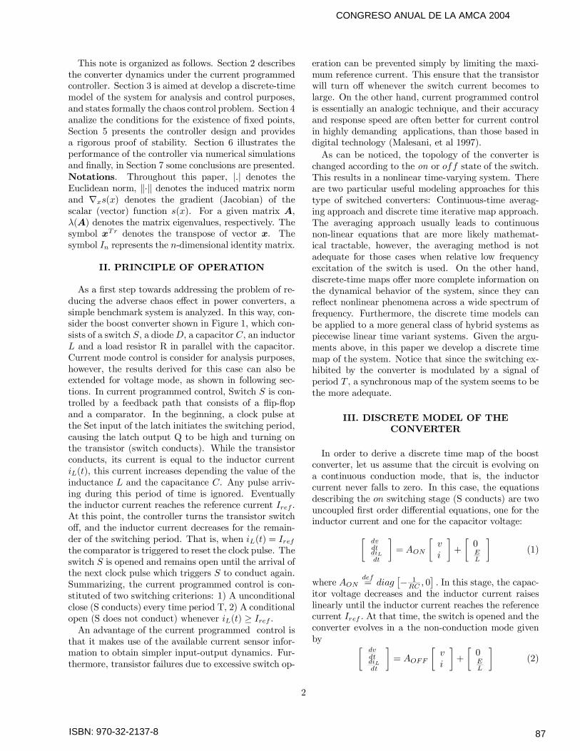
In order to derive a discrete time map of the boostconverter, let us assume that the circuit is evolving ona continuous conduction mode, that is, the inductorcurrent never falls to zero. In this case, the equationsdescribing the on switching stage (S conducts) are twouncoupled first order differential equations, one for theinductor current and one for the capacitor voltage:
dvdtdiLdt
= AONvi
+0EL
(1)
where AONdef= diag − 1
RC , 0 . In this stage, the capac-itor voltage decreases and the inductor current raiseslinearly until the inductor current reaches the referencecurrent Iref . At that time, the switch is opened and theconverter evolves in a the non-conduction mode givenby
dvdtdiLdt
= AOFFvi
+0EL
(2)
2
87
ISBN: 970-32-2137-8
CONGRESO ANUAL DE LA AMCA 2004
whereAOFFdef=
− 1RC
1C− 1
L0
is an invertible and Hur-
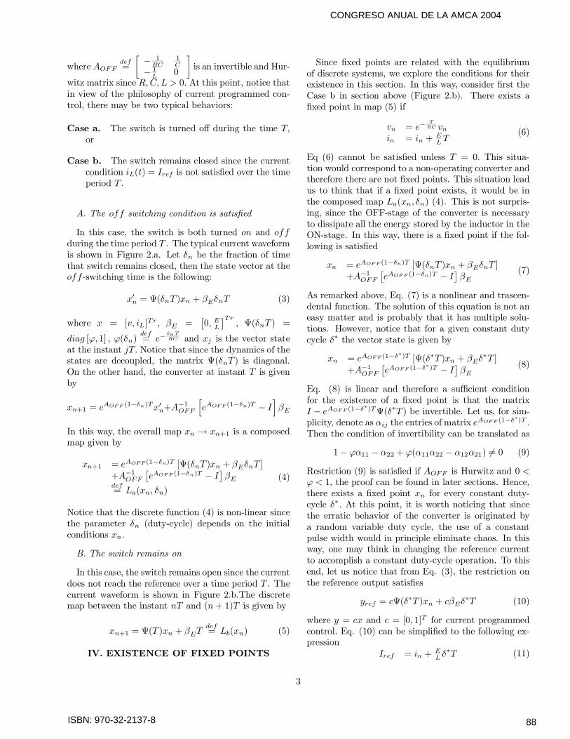
witz matrix since R,C, L > 0. At this point, notice thatin view of the philosophy of current programmed con-trol, there may be two typical behaviors:
Case a. The switch is turned off during the time T,or
Case b. The switch remains closed since the currentcondition iL(t) = Iref is not satisfied over the timeperiod T .
A. The off switching condition is satisfied
In this case, the switch is both turned on and offduring the time period T . The typical current waveformis shown in Figure 2.a. Let δn be the fraction of timethat switch remains closed, then the state vector at theoff -switching time is the following:
xn = Ψ(δnT )xn + βEδnT (3)
where x = [v, iL]Tr, βE = 0, EL
Tr, Ψ(δnT ) =
diag [ϕ, 1] , ϕ(δn)def= e−
δnTRC and xj is the vector state
at the instant jT. Notice that since the dynamics of thestates are decoupled, the matrix Ψ(δnT ) is diagonal.On the other hand, the converter at instant T is givenby
xn+1 = eAOFF (1−δn)Txn+A
−1OFF eAOFF (1−δn)T − I βE
In this way, the overall map xn → xn+1 is a composedmap given by
xn+1 = eAOFF (1−δn)T [Ψ(δnT )xn + βEδnT ]+A−1OFF eAOFF (1−δn)T − I βEdef= La(xn, δn)
(4)
Notice that the discrete function (4) is non-linear sincethe parameter δn (duty-cycle) depends on the initialconditions xn.
B. The switch remains on
In this case, the switch remains open since the currentdoes not reach the reference over a time period T . Thecurrent waveform is shown in Figure 2.b.The discretemap between the instant nT and (n+ 1)T is given by
xn+1 = Ψ(T )xn + βETdef= Lb(xn) (5)
IV. EXISTENCE OF FIXED POINTS
Since fixed points are related with the equilibriumof discrete systems, we explore the conditions for theirexistence in this section. In this way, consider first theCase b in section above (Figure 2.b). There exists afixed point in map (5) if
vn = e−TRC vn
in = in +ELT
(6)
Eq (6) cannot be satisfied unless T = 0. This situa-tion would correspond to a non-operating converter andtherefore there are not fixed points. This situation leadus to think that if a fixed point exists, it would be inthe composed map La(xn, δn) (4). This is not surpris-ing, since the OFF-stage of the converter is necessaryto dissipate all the energy stored by the inductor in theON-stage. In this way, there is a fixed point if the fol-lowing is satisfied
xn = eAOFF (1−δn)T [Ψ(δnT )xn + βEδnT ]+A−1OFF eAOFF (1−δn)T − I βE
(7)
As remarked above, Eq. (7) is a nonlinear and trascen-dental function. The solution of this equation is not aneasy matter and is probably that it has multiple solu-tions. However, notice that for a given constant dutycycle δ∗ the vector state is given by
xn = eAOFF (1−δ∗)T [Ψ(δ∗T )xn + βEδ
∗T ]+A−1OFF eAOFF (1−δ
∗)T − I βE(8)
Eq. (8) is linear and therefore a sufficient conditionfor the existence of a fixed point is that the matrixI − eAOFF (1−δ∗)TΨ(δ∗T ) be invertible. Let us, for sim-plicity, denote as αij the entries of matrix eAOFF (1−δ
∗)T .Then the condition of invertibility can be translated as
1− ϕα11 − α22 + ϕ(α11α22 − α12α21) = 0 (9)
Restriction (9) is satisfied if AOFF is Hurwitz and 0 <ϕ < 1, the proof can be found in later sections. Hence,there exists a fixed point xn for every constant duty-cycle δ∗. At this point, it is worth noticing that sincethe erratic behavior of the converter is originated bya random variable duty cycle, the use of a constantpulse width would in principle eliminate chaos. In thisway, one may think in changing the reference currentto accomplish a constant duty-cycle operation. To thisend, let us notice that from Eq. (3), the restriction onthe reference output satisfies
yref = cΨ(δ∗T )xn + cβEδ
∗T (10)
where y = cx and c = [0, 1]T for current programmedcontrol. Eq. (10) can be simplified to the following ex-pression
Iref = in +EL δ∗T (11)
3
88

ISBN: 970-32-2137-8
CONGRESO ANUAL DE LA AMCA 2004
Notice that for every δ∗ there is one and only one Iref .If Iref is defined as a control variable, Eq. (11) consti-tutes a discrete control law that makes use informationof the inductor current at every instant nT. It can beproved that control law (10) (alternately (11)) leads toasymptotic stability of the closed-loop system. This re-sult is formalized in following Section and constitutesthe main result of this note. As a preliminary step ofthis proof, consider the following results.
Lemma 1 (Chen, 1999). Let P be a Hurwitz matrix,then eP is Schur.
Lemma 2 Let eP ∈ R2 be a Schur matrix and Π =diag[π, 1] with 0 < π < 1, then ePΠ is Schur.
Proof. Let pij denote the entries of eP , then its char-acteristic equation is given by f1(λ) = λ2− (p11+p22)λ+p11p22− p12p21. Since the matrix eP is Schur it satis-fies the following (Chen, 1999)
1− p11 − p22 + p11p22 − p12p21 > 01 + p11 + p22 + p11p22 − p12p21 > 0
p11p22 − p12p21 < 1(12)
furthermore since det(eP ) = etrace(P ) > 0, 0 <det(eP ) < 1. Therefore, from (12) one can see that p11satisfies
−2− p22 < p11 < 2− p22On the other hand, the characteristic equation of ePΠis given by
f2(λ) = λ2 − (πp11 + p22)λ+ π(p11p22 − p12p21)
which is Schur if satisfies
1− πp11 − p22 + π (p11p22 − p12p21) > 01 + πp11 + p22 + π (p11p22 − p12p21) > 0
π (p11p22 − p12p21) < 1(13)
Since 0 < π < 1 the last restriction in (13) is satisfied.On the other hand, (13) implies that −2−p22π < p11 <2−p22π . Notice that since −2−p22π < −2 − p22, 2−p22π >
2 − p22 (13) is satisfied, leading us to conclude thatmatrix ePΠ is Schur. This concludes the proof
Remark 1 From Lemma 2, one can also conclude theexistence of a fixed point in map (8). Since restrictionthe satisfaction of restriction (13) guarantees the satis-faction of (9).
V. MAIN RESULT
The main contribution of this note is presented belowin the following theorem
Theorem 3 Consider the converter dynamics undercurrent programmed control and the feedback expression(10), then the closed-loop system is globally asymptoti-cally stable about the equilibrium point
x = I − eAOFF (1−δ∗)TΨ(δ∗T ) −1 eAOFF (1−δ∗)TβEδ∗T+ A−1OFF eAOFF (1−δ
∗)T − I βE(14)
Proof. The closed loop equations are given by
xn+1 = eAOFF (1−δ∗)TΨ(δ∗T )xn + eAOFF (1−δ
∗)TβEδ∗T
+A−1OFF eAOFF (1−δ∗)T − I βE
(15)Notice that the stability of the discrete-time system (15)is ensured if the matrix eAOFF (1−δ
∗)TΨ(δ∗T ) is Schur.Since (1 − δ∗)T > 0, the result in Lemma 1 impliesthat matrix eAOFF (1−δ
∗)T is Schur. From Lemma 2, onecan conclude that eAOFF (1−δ
∗)TΨ(δ∗T ) is also Schur,since 0 < ϕ < 1. Therefore system (15) is globally as-ymptotically stable about the equilibrium point (14).The existence of such equilibrium is guaranteed since,as shown before, matrix I − eAOFF (1−δ∗)TΨ(δ∗T ) is in-vertible. This concludes the proof
Remark 2 Result in Theorem 3 establish that by defin-ing the reference as in (10), any possible erratic behav-ior of the system under current programed control iseliminated. Even more, the result presented in this noteis also valid for voltage programmed control (VPC) just
by defining the output vector in (10) as c = [1, 0]T.
Remark 3 Although system stability under CPC orVPC is ensured by feedback control law (10), the regula-tion voltage problem is not necessary solved. However,given that for every δ∗ there exists one and only onefixed point x, one can follow the methodology given in(Cervantes et al 2003, Alvarez et al. 2002) to design anouter-loop in order to obtain a desired output voltage.
Remark 4 As stated before, Theorem 3 establish theconditions to derive global asymptotic stability of theconverter under control law (10) to the fixed point (14).At this point, one may wonder if this result is preservedin presence of parametric uncertainty. Deriving a for-mal stability result of this case is quite involved , how-ever as we will see later, the control law (10) is able tostabilize the system even if the parameters are uncer-tain. This fact is illustrated via numerical simulationsin Section above.
Remark 5 Given the linear nature of the control law(10) it can be easily implemented. In principle, suchcircuit would require of an operational amplifier and a”sample and hold” circuit.
4
89
ISBN: 970-32-2137-8
CONGRESO ANUAL DE LA AMCA 2004
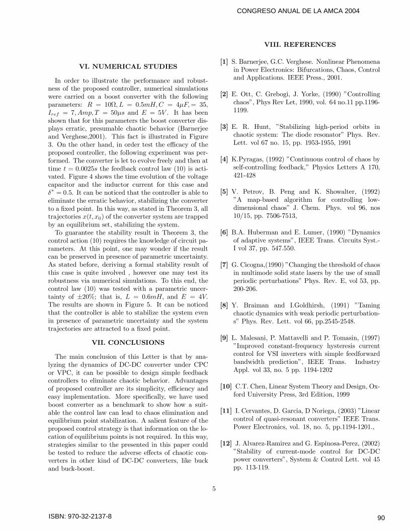
VI. NUMERICAL STUDIES
In order to illustrate the performance and robust-ness of the proposed controller, numerical simulationswere carried on a boost converter with the followingparameters: R = 10Ω, L = 0.5mH,C = 4µF,= 35,Iref = 7,Amp,T = 50µs and E = 5V . It has beenshown that for this parameters the boost converter dis-plays erratic, presumable chaotic behavior (Barnerjeeand Verghese,2001). This fact is illustrated in Figure3. On the other hand, in order test the efficacy of theproposed controller, the following experiment was per-formed. The converter is let to evolve freely and then attime t = 0.0025s the feedback control law (10) is acti-vated. Figure 4 shows the time evolution of the voltagecapacitor and the inductor current for this case andδ∗ = 0.5. It can be noticed that the controller is able toeliminate the erratic behavior, stabilizing the converterto a fixed point. In this way, as stated in Theorem 3, alltrajectories x(t, x0) of the converter system are trappedby an equilibrium set, stabilizing the system.To guarantee the stability result in Theorem 3, the
control action (10) requires the knowledge of circuit pa-rameters. At this point, one may wonder if the resultcan be preserved in presence of parametric uncertainty.As stated before, deriving a formal stability result ofthis case is quite involved , however one may test itsrobustness via numerical simulations. To this end, thecontrol law (10) was tested with a parametric uncer-tainty of ±20%; that is, L = 0.6mH, and E = 4V.The results are shown in Figure 5. It can be noticedthat the controller is able to stabilize the system evenin presence of parametric uncertainty and the systemtrajectories are attracted to a fixed point.
VII. CONCLUSIONS
The main conclusion of this Letter is that by ana-lyzing the dynamics of DC-DC converter under CPCor VPC, it can be possible to design simple feedbackcontrollers to eliminate chaotic behavior. Advantagesof proposed controller are its simplicity, efficiency andeasy implementation. More specifically, we have usedboost converter as a benchmark to show how a suit-able the control law can lead to chaos elimination andequilibrium point stabilization. A salient feature of theproposed control strategy is that information on the lo-cation of equilibrium points is not required. In this way,strategies similar to the presented in this paper couldbe tested to reduce the adverse effects of chaotic con-verters in other kind of DC-DC converters, like buckand buck-boost.
VIII. REFERENCES
[1] S. Barnerjee, G.C. Verghese. Nonlinear Phenomenain Power Electronics: Bifurcations, Chaos, Controland Applications. IEEE Press., 2001.
[2] E. Ott, C. Grebogi, J. Yorke, (1990) ”Controllingchaos”, Phys Rev Let, 1990, vol. 64 no.11 pp.1196-1199.
[3] E. R. Hunt, ”Stabilizing high-period orbits inchaotic system: The diode resonator” Phys. Rev.Lett. vol 67 no. 15, pp. 1953-1955, 1991
[4] K.Pyragas, (1992) ”Continuous control of chaos byself-controlling feedback,” Physics Letters A 170,421-428
[5] V. Petrov, B. Peng and K. Showalter, (1992)”A map-based algorithm for controlling low-dimensional chaos” J. Chem. Phys. vol 96, nos10/15, pp. 7506-7513,
[6] B.A. Huberman and E. Lumer, (1990) ”Dynamicsof adaptive systems”, IEEE Trans. Circuits Syst.-I vol 37, pp. 547.550.
[7] G. Cicogna,(1990) ”Changing the threshold of chaosin multimode solid state lasers by the use of smallperiodic perturbations” Phys. Rev. E, vol 53, pp.200-206.
[8] Y. Braiman and I.Goldhirsh, (1991) ”Tamingchaotic dynamics with weak periodic perturbation-s” Phys. Rev. Lett. vol 66, pp.2545-2548.
[9] L. Malesani, P. Mattavelli and P. Tomasin, (1997)”Improved constant-frequency hysteresis currentcontrol for VSI inverters with simple feedforwardbandwidth prediction”, IEEE Trans. IndustryAppl. vol 33, no. 5 pp. 1194-1202
[10] C.T. Chen, Linear System Theory and Design, Ox-ford University Press, 3rd Edition, 1999
[11] I. Cervantes, D. Garcia, D Noriega, (2003) ”Linearcontrol of quasi-resonant converters” IEEE Trans.Power Electronics, vol. 18, no. 5, pp.1194-1201.,
[12] J. Alvarez-Ramirez and G. Espinosa-Perez, (2002)”Stability of current-mode control for DC-DCpower converters”, System & Control Lett. vol 45pp. 113-119.
5
90

ISBN: 970-32-2137-8
CONGRESO ANUAL DE LA AMCA 2004
Figure 1. Boost converter
0.0000 0.0002 0.0004 0.0006 0.0008 0.00100
2
4
6
8
10
(b)
(n-1) T nT (n+1) T
Iref
Indu
ctor
Cur
rent
Time
0 2 4 6 8 100
2
4
6
8
10
(a)
Irefx'
xn+1
xn
nT (n+1) T(n-1)T
Indu
ctor
Cur
rent
Time
Figure 2. Typical current waveforms of the converterunder CPC.
0.0 1.5 3.0 4.5 6.0 7.5 9.0-5
0
5
10
15
20
25
30
35
40
45
50
55
Ou
tput
V
olta
ge (
V)
Reference Current (Amp)
Figure 3. Bifurcation digaram with reference currentas parameter.
0.00 2.50x10 -3 5.00x10 -3 7.50x10 -3
0
10
20
30
40
50
0.00 2.50x10⁻³
5.00x10⁻³
7.50x10⁻³
0
1
2
3
4
5
6
7
0.00 2.50x10 -3 5.00x10 -3 7.50x10 -3
2
3
4
5
6
7
Ou
tput
Vol
tage
(V
)
Time (s)
Indu
ctor
Cur
rent
(A
mp)
Ref
eren
ce C
urre
nt (
Am
p)
Figure 4. Time evolution of the system with theproposed controller.
0.00 2.50x10 -3 5.00x10 -3 7.50x10 -3
0
10
20
30
40
50
0.00 2.50x10⁻³
5.00x10⁻³
7.50x10⁻³
0
1
2
3
4
5
6
7
0.00 2.50x10 -3 5.00x10 -3 7.50x10 -3
1
2
3
4
5
6
7
Out
put V
olta
ge (
V)
Time (s)
Indu
ctor
Cur
rent
(A
mp)
Ref
eren
ce C
urre
nt (
Am
p)
Figure 5. Time evolution of the system with theproposed controller in presence of parametric
uncertainty.
6
91