Embed Size (px)
Citation preview

Introduction 1MPL 1640 Features 1
Guided Tour 3Overview 3Channel 4Main Section 6Rear Panel 8
Connecting the MPL 1640 10Balanced connectors 10Unbalanced connectors 10Mic connectors 10Insert connectors 11
Setting Up and Using the MPL 1640 12Setting the correct gain structure 12
Grounding Techniques 15
Using Bus 3/4 17
Using Pan 18
Using Equalization 19
Using the Auxiliary Sends and Returns 20
Using Channel Inserts 21
Using PFL Solo 22
Changing the MPL 1640 from Rack-mount toTabletop 23
Applications 24Using the MPL 1640 as a main live mixer 24Using the MPL 1640 as an onstage monitor mixer 25Using the MPL 1640 as a keyboard submixer 26Using the MPL 1640 as a recording mixer 27
Appendix A: Changing the MPL 1640 Voltage 28
Appendix B: Block Diagram 29
Specifications 30

Introduction
Congratulations on purchasing the Samson MPL 1640 mixer! In this manual,we’ll take you on a guided tour through all the features of this powerful and flexi-ble device, and we’ll tell you how to get the most out of the MPL 1640 in yourparticular environment. If this is your first mixer, we’re confident that you’ll findthe information in these pages valuable—read them carefully before proceedingfurther. If, on the other hand, you’ve had some previous experience with mixersand dislike reading manuals—well, we have to admit that the 1640 wasdesigned so you folks can start using it right away—but we still suggest you firsttake some time to go through these pages so you can fully understand howwe’ve implemented a number of unique features.
We’ll start with system features and an overview of the MPL 1640, followed by aguided tour of its front and rear panels. Then we’ll describe how the MPL 1640should be connected to your existing equipment (including wiring diagrams) andtalk about the important topics of signal flow, gain structure, and groundingtechniques. Next, we’ll cover a number of specific MPL 1640 features (such asbusing, panning, equalization, auxiliary sends and returns, channel inserts, andsoloing) in detail. Finally, we’ll wrap things up with a series of applications notesdescribing how you can use the MPL 1640 for both live performance andrecording.
Oh, and one last thing—don’t forget to fill out and mail in the enclosed warrantycard! This will enable you to receive online technical support and will allow us tosend you updated information about this and other Samson products in thefuture.
SPECIAL NOTE: Should your unit ever require servicing, a Return Authorizationnumber (RA) is necessary. Without this number, the unit will not be accepted.Please call Samson at (516) 932-1062 for a Return Authorization number priorto shipping your unit. Please retain the original packing materials and, ifpossible, return the unit in its original carton and packing materials.
MPL 1640 Features
“MPL” stands for “Microphone/Program/Line” and the name describes the broadrange of signals which can be handled by this powerful console. In fact, thecompact design of the MPL 1640 belies an extraordinary versatility. Add excel-lent sound quality to the equation, and you’ve got a product which is equallyuseful as a live performance mixer, a keyboard submixer, or even a mainrecording mixer (you’ll find descriptions of each of these applications at theconclusion of this manual). Here are some of the MPL 1640’s main features:
• 16 input channels, each providing electronically balanced inputs that can beused for a broad range of microphone or line-level input sources.
• An electronically balanced main stereo output for connection to a poweramplifier or tape recorder, as well as a secondary Bus 3/4 output for connec-tion to auxiliary equipment such as a monitoring system.
1

Introduction
• 3 auxiliary sends and 3 stereo auxiliary returns (which can be used as 6monophonic returns). Auxiliary return balance controls allow you to adjustthe relative levels of the left and right inputs for each return. Aux send 1 ispre-fader and pre-equalizer, making it ideal for use as a headphone or moni-tor cue mix, while Aux sends 2 and 3 are post-fader and post-equalizer.
• Independent 3-band equalization for each channel, with 15 dB of cut or boostfor low (80 Hz) and high (10 kHz) frequencies and 12 dB of cut or boost forthe mid (800 Hz) frequency.
• Constant level pan controls for placing each channel in the left-right stereospectrum.
• Channel PFL (Pre-Fade Listen) switches enable channels to be selectivelysoloed.
• Bus switches on each channel allow signal to be muted or routed to aseparate stereo Bus 3/4 output.
• Channel input trim controls are continuously adjustable from +4 to -50 dB,making it possible to use the MPL 1640 with a wide variety of signal sourcesand outboard equipment.
• Center detents for all pan, balance, and EQ controls, making it easy to usethe MPL 1640 even in low-light situations such as live performance.
• Sixteen high-quality short-throw channel faders, along with two independentMain stereo output faders. Each is detented at its “0” (unity gain) position.
• Peak input LEDs for each channel, showing you when an input signal isoverloading or near overloading (these illuminate 5 dB prior to distortion).
• Channel inserts for twelve of the sixteen channels, enabling you to use out-board signal processors such as outboard equalizers, compressor/ limiters,or noise gates in a standard “effect loop.” In addition, Main Mix and Bus 3/4inserts allow you to process the final output signal in the same way.
• The provision of 48v phantom power makes it possible to plug high-qualitycondenser microphones directly into the MPL 1640, without the need forexpensive and cumbersome external power supplies.
• A powerful and flexible front-panel metering system, which includes a seven-segment meter that allows you to view at a glance the continuous main out-put level or PFL solo level. Also included are various LEDs which show thestatus of various conditions within the MPL 1640.
• An independent front-panel headphone jack with dedicated volume control.
• The MPL 1640 can be mounted in any standard 19” rack (taking 8 rackspaces), making it easy to integrate into any existing system. When rack-mounted, its connector panel rotates to the rear for easy accessibility.
• Last but certainly not least, an affordable price. The MPL 1640 has beendesigned from the ground up to provide versatility and excellent soundquality without breaking the bank.
2
Guided Tour - Overview
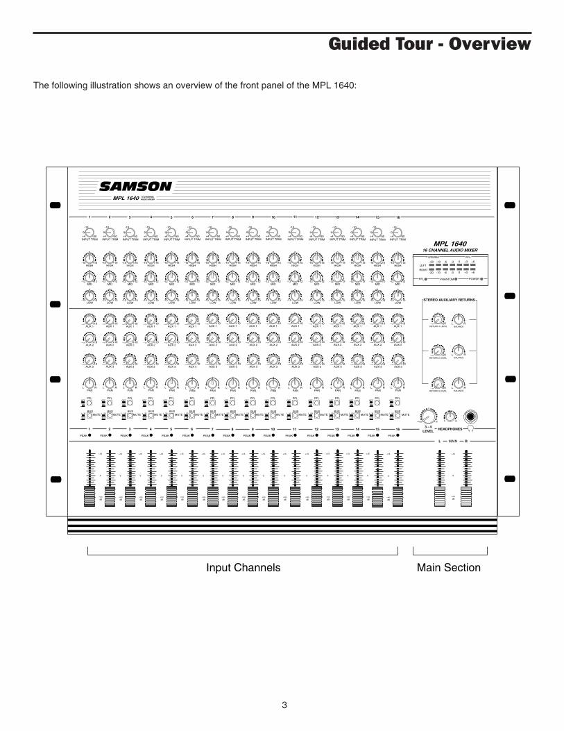
The following illustration shows an overview of the front panel of the MPL 1640:
3
+4 -50INPUT TRIM
0
-10
-15 +15HIGH
0
-12 +12MID
0
-15 +15LOW
0
+10AUX 1
0
−∞
+10AUX 2
0
−∞
+10AUX 3
0
−∞
PFL
BUS
ON
OFF
3 / 4
L / R
1
-∞dB
PEAK
+4 -50INPUT TRIM
0
-10
-15 +15HIGH
0
-12 +12MID
0
-15 +15LOW
0
+10AUX 1
0
−∞
+10AUX 2
0
−∞
+10AUX 3
0
−∞
RPAN
L
16
PEAK
+4 -50INPUT TRIM
0
-10
-15 +15HIGH
0
-12 +12MID
0
-15 +15LOW
0
+10AUX 1
0
−∞
+10AUX 2
0
−∞
AUX 3
0
−∞
12
PEAK
+4 -50INPUT TRIM
0
-10
-15 +15HIGH
0
-12 +12MID
0
-15 +15LOW
0
+10AUX 1
0
−∞
+10AUX 2
0
−∞
+10AUX 3
0
−∞
6
PEAK
+4 -50INPUT TRIM
0
-10
-15 +15HIGH
0
-12 +12MID
0
-15 +15LOW
0
+10AUX 1
0
−∞
+10AUX 2
0
−∞
+10AUX 3
0
−∞
2
+15
0
PEAK
+4 -50INPUT TRIM
0
-10
-15 +15HIGH
0
-12 +12MID
0
-15 +15LOW
0
+10AUX 1
0
−∞
+10AUX 2
0
−∞
+10AUX 3
0
−∞
3
PEAK
+4 -50INPUT TRIM
0
-10
-15 +15HIGH
0
-12 +12MID
0
-15 +15LOW
0
+10AUX 1
0
−∞
+10AUX 2
0
−∞
+10AUX 3
0
−∞
4
PEAK
+4 -50INPUT TRIM
0
-10
-15 +15HIGH
0
-12 +12MID
0
-15 +15LOW
0
+10AUX 1
0
−∞
+10AUX 2
0
−∞
+10AUX 3
0
−∞
5
PEAK
+4 -50INPUT TRIM
0
-10
-15 +15HIGH
0
-12 +12MID
0
-15 +15LOW
0
+10AUX 1
0
−∞
+10AUX 2
0
−∞
+10AUX 3
0
−∞
7
PEAK
+4 -50INPUT TRIM
0
-10
-15 +15HIGH
0
-12 +12MID
0
-15 +15LOW
0
+10AUX 1
0
−∞
+10AUX 2
0
−∞
+10AUX 3
0
−∞
8
PEAK
+4 -50INPUT TRIM
0
-10
-15 +15HIGH
0
-12 +12MID
0
-15 +15LOW
0
+10AUX 1
0
−∞
+10AUX 2
0
−∞
+10AUX 3
0
−∞
9
PEAK
+4 -50INPUT TRIM
0
-10
-15 +15HIGH
0
-12 +12MID
0
-15 +15LOW
0
+10AUX 1
0
−∞
+10AUX 2
0
−∞
+10AUX 3
0
−∞
10
PEAK
+4 -50INPUT TRIM
0
-10
-15 +15HIGH
0
-12 +12MID
0
-15 +15LOW
0
+10AUX 1
0
−∞
+10AUX 2
0
−∞
+10AUX 3
0
−∞
11
PEAK
+10
+4 -50INPUT TRIM
0
-10
-15 +15HIGH
0
-12 +12MID
0
-15 +15LOW
0
+10AUX 1
0
−∞
+10AUX 2
0
−∞
AUX 3
0
−∞
13
PEAK
+10
+4 -50INPUT TRIM
0
-10
-15 +15HIGH
0
-12 +12MID
0
-15 +15LOW
0
+10AUX 1
0
−∞
+10AUX 2
0
−∞
AUX 3
0
−∞
14
PEAK
+10
+4 -50INPUT TRIM
0
-10
-15 +15HIGH
0
-12 +12MID
0
-15 +15LOW
0
+10AUX 1
0
−∞
+10AUX 2
0
−∞
AUX 3
0
−∞
15
PEAK
+10
L R
RPAN
LRPAN
LRPAN
LRPAN
LRPAN
LRPAN
LRPAN
LRPAN
LRPAN
LRPAN
LRPAN
LRPAN
LRPAN
LRPAN
LRPAN
L
+20RETURN 1 LEVEL
0
−∞
+20
0
−∞RETURN 2 LEVEL
+20
0
−∞RETURN 3 LEVEL
RBALANCE
L
RBALANCE
L
RBALANCE
L
HEADPHONES3 - 4
LEVEL
0 10−∞ +15
STEREO AUXILIARY RETURNS
1 2 3 4 5 6 7 8 9 10 11 12 13 14 15 16
STERE0 PFL
LEFT
RIGHT
PFL PHANTOM POWER
-20 -10 -6 -3 0 +3 +6
-20 -10 -6 -3 0 +3 +6
16 CHANNEL AUDIO MIXERMPL 1640
MPL 1640 16 CHANNELAUDIO MIXER
-∞dB
+15
0
-∞dB
+15
0
-∞dB
+15
0
-∞dB
+15
0
-∞dB
+15
0
-∞dB
+15
0
-∞dB
+15
0
-∞dB
+15
0
-∞dB
+15
0
-∞dB
+15
0
-∞dB
+15
0
-∞dB
+15
0
-∞dB
+15
0
-∞dB
+15
0
-∞dB
+15
0
MAIN
PFL
BUS
ON
OFF
3 / 4
L / R
PFL
BUS
ON
OFF
3 / 4
L / R
PFL
BUS
ON
OFF
3 / 4
L / R
PFL
BUS
ON
OFF
3 / 4
L / R
PFL
BUS
ON
OFF
3 / 4
L / R
PFL
BUS
ON
OFF
3 / 4
L / R
PFL
BUS
ON
OFF
3 / 4
L / R
PFL
BUS
ON
OFF
3 / 4
L / R
PFL
BUS
ON
OFF
3 / 4
L / R
PFL
BUS
ON
OFF
3 / 4
L / R
PFL
BUS
ON
OFF
3 / 4
L / R
PFL
BUS
ON
OFF
3 / 4
L / R
PFL
BUS
ON
OFF
3 / 4
L / R
PFL
BUS
ON
OFF
3 / 4
L / R
PFL
BUS
ON
OFF
3 / 4
L / R
SAMSON
MUTEMUTEMUTEMUTEMUTEMUTE MUTEMUTEMUTEMUTEMUTEMUTEMUTEMUTEMUTE MUTE
Main SectionInput Channels
0

Guided Tour - Channel
Let’s start our guided tour by examining the various controls provided by eachchannel:
1: Input Trim (black) - This knob determines the input level of the connectedmic or line signal. Continuously adjustable from +4 dB to -50 dB, the input trim isat unity gain (no boost or cut) when set to the 0 position. The input signal isboosted when the knob is turned to the right of 0 and attenuated when turned tothe left of 0. For information on how to properly set this for each channel, see thesection on page 12 entitled “Setting The Correct Gain Structure.”
2: Equalizer (blue) - These knobs determine the amount of boost or attenuationin each of three frequency areas. The “High” and “Low” frequency knobs provide15 dB of cut or boost at 10 kHz and 80 Hz, respectively, with shelving-typecontrol. The “Mid” frequency knob provides 12 dB of cut or boost at 800 Hz, witha bell (peaking) curve. A center detent in each knob (at the 12 o’clock position)indicates no boost or attenuation (that is, flat response). As each knob is turnedclockwise from the center detent position, the frequency area is boosted; as it isturned counterclockwise from the center detent position, the frequency area isattenuated. For more information on the application of EQ, see the “UsingEqualization” section on page 19 of this manual.
3: Auxiliary sends (light gray) - These knobs allow you to route signal to any ofthe MPL 1640’s three monophonic auxiliary outputs. These are typically used tocreate submixes (for example, a monitor mix or headphone cue mix) or to feedsignal from single or multiple channels to outboard effects devices. At the 0 posi-tion, the send signal is routed with unity gain (that is, no boost or attenuation).As each knob is turned clockwise from the 0 position, the signal is boosted; as itis turned counterclockwise from the 0 position, it is attenuated. At the fullycounterclockwise “-∞” position, the send signal is infinitely attenuated—that is,no signal is routed. At the fully clockwise “+10” position, the send signal is routedwith 10 dB of gain. Auxiliary send 1 is always pre-fader; that is, the level of thesend signal is determined solely by the channel’s input trim and is unaffected byits fader position and EQ settings. Auxiliary sends 2 and 3 are post-fader; that is,the level of the send signal is determined by the channel’s input trim, its EQsettings, and the position of its fader.
4: Pan (white) - This knob allows you to place each channel’s signal anywherein the left-right stereo spectrum, while keeping the overall signal level constant.When the knob is placed at its center (detented) position, the signal is sentequally to both left and right outputs. When moved left of center, less signal issent to the right output (making the sound appear left of center) and when movedright of center, less signal is sent to the left output (making the sound appearright of center). To route a signal hard left or right, place the pan knob either fullycounterclockwise or fully clockwise. See the “Using Pan” section on page 18 ofthis manual for more information.
5: PFL switch (gray) - When pressed in, the channel is soloed in PFL (Pre-FadeListen) mode, affecting headphone monitoring only. For more information, seethe section on page 22 entitled “Using PFL Solo.”
4
+4 -50INPUT TRIM
0
-10
-15 +15HIGH
0
-12 +12MID
0
-15 +15LOW
0
+10AUX 1
0
−∞
+10AUX 2
0
−∞
+10AUX 3
0
−∞
PFL
BUS
ON
OFF
3 / 4
L / R
1
-∞dB
PEAK
+15
0
RPAN
L
1
MUTE
1
2
3
4
5
6
7
8

Guided Tour - Channel
6: Bus switch (gray) - When up, the channel’s signal is routed to the Main L/Rfaders (as described on page 7) and then on to the MPL 1640 Main Mix outputjacks (as described on page 8). When pressed in, the channel’s signal isremoved from the Main L/R output and is instead routed to the 3/4 Level knob(as described on page 6) and then to the 3L/4R output jacks (as described onpage 8). If you don‘t have anything connected to the MPL 1640 Bus 3/4 outputjacks, this switch can be used for channel muting. See the “Using Bus 3/4”section on page 17 for more information.
7: Peak LED (red) - This warning light indicates an overload situation. It lightswhenever a channel’s signal is 5 dB short of clipping. To stop it from lighting(and to eliminate the accompanying sonic distortion), turn down the channel’sTrim knob (see #1 on the previous page) or reduce the amount of equalizationboost. See the “Setting the Correct Gain Structure” and “Using Equalization”sections on pages 12 and 19 for more information.
8: Channel fader (gray with a blue line) - This linear slider determines the signallevel being sent to the main output as well as affecting the signal level beingrouted to Aux sends 2 and 3 (which are post-fader; Aux 1 is always pre-fader).In practice, you will use the channel faders to continuously adjust the levels ofthe various signals being blended together by the MPL 1640. The detented “0”position of the fader indicates unity gain (no level attenuation or boost). Movingthe fader down from the “0” position (towards “-∞”) causes the signal to be atten-uated (at the very bottom, it is attenuated infinitely—in other words, there is nosound). Moving it up from the “0” position (towards “+15”) causes the signal tobe boosted by as much as 15 dB.
For best signal-to-noise ratio, all faders for channels carrying signal should gen-erally be kept at or near the “0” detented position. Channels that are unusedshould have their faders kept all the way down at their "-∞" (minimum) level. Seethe “Setting the Correct Gain Structure” section on page 12 for more information.
5

Guided Tour - Main Section
1: Meter - This seven-segment bar meter shows the continuous output level ofthe Main L/R stereo output. For optimum signal-to-noise ratio, try to adjust alllevels so that program material is usually at or around 0 VU, with occasional butnot steady excursions to the red +3 or +6 segments. See the “Setting theCorrect Gain Structure” section on page 12 for more information.
2: Meter LEDs - These show the status of various conditions within the MPL1640. The bottom left LED (labeled “PFL”) lights steadily red whenever one ormore channels is soloed. The bottom center LED (labeled “Phantom”) lightssteadily red when Phantom power is being supplied to all mic connectors (see #1on page 8 of this manual for more information). The bottom right LED (labeled“Power”) lights steadily red whenever the MPL 1640 is powered on.
3: Stereo Auxiliary Return Level (green) - These knobs determine the inputlevel of signal arriving via the MPL 1640’s three stereo Auxiliary returns. Eachreturn is at unity gain (no boost or attenuation) when set to the 0 position. Theinput signal is boosted when the knob is turned to the right of 0 and attenuatedwhen turned to the left of 0. When turned fully clockwise (to the “+20” position),the return signal is boosted by 20 dB; when turned fully counterclockwise (to the“-∞” position), the return signal is infinitely attenuated—that is, there is no sound.For information on how to properly set these, see the sections on pages 12 and20 entitled “Setting the Correct Gain Structure” and “Using the Auxiliary Sendsand Returns.”
4: Stereo Auxiliary Return Balance (dark gray) - These knobs determine therelative levels of the left and right input signals connected to the MPL 1640’sthree stereo Auxiliary returns. When the knob is placed at its center (detented)position, both left and right input signals for that Aux return are at equal strength.When moved left of center, the left input signal remains at the same strength butthe right input signal is attenuated; when the knob is moved right of center, theright input signal remains at the same strength but the left input signal is attenu-ated. When placed fully counter-clockwise, only the left input signal is heard(panned hard left); when placed fully clockwise, only the right input signal isheard (panned hard right). These “radical” positions are useful when you areusing a stereo Aux return as two mono returns—see the “Using the AuxiliarySends and Returns” section on page 20 for more information.
When only the left input of an Aux return is connected, its Balance knob func-tions as a constant level Pan control, allowing you to continuously place theincoming signal anywhere in the left-right stereo field.
5: 3/4 Level (green) - This knob determines the final output level of the Bus 3/4signal. We made this knob extra big so you won’t miss it even under low-lightperformance conditions. Signals from all channels that have their Busswitch (see page 5) set to the “3/4” position are routed here prior to being sent tothe rear panel 3/4 output jacks (as described on on page 8). The center detent-ed “0” position of the knob indicates unity gain (no level attenuation or boost).Moving the knob counterclockwise from the “0” position (towards “-∞”) causesthe signal to be attenuated (at the fully counterclockwise position, it is attenuatedinfinitely—in other words, there is no sound). Moving the knob clockwise fromthe “0” position (towards “+15”) causes the signal to be boosted by as much as15 dB. For more information, see the “Using Bus 3/4” section on page 17 of thismanual.
L R
+20RETURN 1 LEVEL
0
−∞
+20
0
−∞RETURN 2 LEVEL
+20
0
−∞RETURN 3 LEVEL
RBALANCE
L
RBALANCE
L
RBALANCE
L
HEADPHONES3 - 4
LEVEL
0 10−∞ +15
STEREO AUXILIARY RETURNS
STERE0 PFL
LEFT
RIGHT
PFL PHANTOM POWER
-20 -10 -6 -3 0 +3 +6
-20 -10 -6 -3 0 +3 +6
16 CHANNEL AUDIO MIXERMPL 1640
-∞dB
+15
0
MAIN
1
2
43
5
6
7
8
0
6

Guided Tour - Main Section
6: Headphones control (black) - This knob sets the level of the signal sent tothe headphone jack (see #7 below). WARNING: To avoid possible damageto connected headphones (or, worse yet, to your ears!), always turn this allthe way off (to the fully counterclockwise “0” position) before plugging in apair of headphones—then raise the level slowly while listening. TheHeadphones control has no effect on the final Main Mix or Bus 3/4 output levels.
7: Headphone jack - Connect any standard stereo headphones to this jack (viaa standard 1/4” TRS plug) for private monitoring of the main stereo output. Thebuilt-in MPL 1640 headphone preamp delivers 150 mw at 30 ohms.
8: Main L/R Faders (white with blue line) - These linear sliders determine therelative level of the two Main Left/Right outputs just prior to being sent to the rearpanel Main Mix output jacks (as described on page 8). The “0” (detented)position of each fader indicates unity gain (no level boost or attenuation).Moving the fader below this position (towards the “-∞” dB position) causes thesignal to be attenuated (at the very bottom, it is attenuated infinitely—in otherwords, there is no sound). Moving it above this position (towards the “+15”position) causes the signal to be boosted by as much as 15 dB.
For best signal-to-noise ratio, both Main L/R faders should generally be kept ator near the detented 0 level. See the “Setting The Correct Gain Structure”section on page 12 of this manual for more information.
7
Guided Tour - Rear Panel
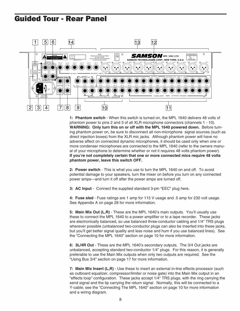
1: Phantom switch - When this switch is turned on, the MPL 1640 delivers 48 volts ofphantom power to pins 2 and 3 of all XLR microphone connectors (channels 1 - 10).WARNING: Only turn this on or off with the MPL 1640 powered down. Before turn-ing phantom power on, be sure to disconnect all non-microphone signal sources (such asdirect injection boxes) from the XLR mic jacks. Although phantom power will have noadverse affect on connected dynamic microphones, it should be used only when one ormore condenser microphones are connected to the MPL 1640 (refer to the owners manu-al of your microphone to determine whether or not it requires 48 volts phantom power).If you’re not completely certain that one or more connected mics require 48 voltsphantom power, leave this switch OFF.
2: Power switch - This is what you use to turn the MPL 1640 on and off. To avoidpotential damage to your speakers, turn the mixer on before you turn on any connectedpower amps—and turn it off after the power amps are turned off.
3: AC Input - Connect the supplied standard 3-pin “EEC” plug here.
4: Fuse sled - Fuse ratings are 1 amp for 115 V usage and .5 amp for 230 volt usage.See Appendix A on page 28 for more information.
5: Main Mix Out (L,R) - These are the MPL 1640’s main outputs. You’ll usually usethese to connect the MPL 1640 to a power amplifier or to a tape recorder. These jacksare electronically balanced, so use balanced three-conductor cabling and 1/4" TRS plugswherever possible (unbalanced two-conductor plugs can also be inserted into these jacks,but you’ll get better signal quality and less noise and hum if you use balanced lines). Seethe “Connecting the MPL 1640” section on page 10 for more information.
6: 3L/4R Out - These are the MPL 1640’s secondary outputs. The 3/4 Out jacks areunbalanced, accepting standard two-conductor 1/4" plugs. For this reason, it is generallypreferable to use the Main Mix outputs when only two outputs are required. See the“Using Bus 3/4” section on page 17 for more information.
7: Main Mix Insert (L,R) - Use these to insert an external in-line effects processor (suchas outboard equalizer, compressor/limiter or noise gate) into the Main Mix output in an“effects loop” configuration. These jacks accept 1/4" TRS plugs, with the ring carrying thesend signal and the tip carrying the return signal. Normally, this will be connected to aY-cable; see the “Connecting The MPL 1640” section on page 10 for more informationand a wiring diagram.
8
12
3
12
3
12
3
12
3
12
3
CH 1CH 2CH 3CH 4CH 5
CH 1CH 2CH 3CH 4CH 5CH 6CH 7CH 8CH 9CH 10CH 11CH 12CH 13CH 14CH 15CH 16
ON
OFF
12
3
CH 6
12
3
CH 7
12
3
CH 8
12
3
CH 9
12
3
CH 10CH 11CH 12CH 13CH 14CH 15CH 16
115
CAUTION
RISK OF ELECTRIC SHOCKDO NOT OPEN
!
ON
OFF
~115V /230V50/60Hz 42W
MAIN MIX OUT(BALANCED 600Ω + 4dB)
POWER
PHANTOM
SERIAL
NUMBER
AVIS:RISQUE DE CHOC ELECTRIQUE
NE PAS OUVRIR.DO NOT EXPOSE THIS EQUIPMENT
TO RAIN OR MOISTURE.
XLR
1 GND2 +3 -
MPL 1640 16 CHANNELAUDIO MIXER
TIP RING SLEEVE
TIP +RING -
SLEEVE GNDASSEMBLED IN R.O.K. SAMSON TECHNOLOGIES CORP., NEW YORK, U.S.A.
SAMSONL
CHANNEL INSERT (TIP RETURN - RING SEND)
AUX 1AUX 23L - 4RMAIN MIX
R
L
AUX 3
AUX 3 AUX 2 AUX 1AUX RETURN (UNBAL.2KΩ + 4dB)
RRR L L L
(BALANCED - 50dB TO + 4dB)MIC INPUT
R3L - 4R(UNBAL.2KΩ +4dB)
BUS INSERT AUX OUT(UNBAL.2KΩ +4dB) LINE INPUT (BALANCED 10 KΩ - 40dB TO + 4dB)
1
2 3 4
5 6
7 8 10 11
121314
9

Guided Tour - Rear Panel
8: Bus Insert - Use these to insert an external in-line effects processor (such as out-board equalizer, compressor/limiter or noise gate) into the Bus 3/4 output in an “effectsloop” configuration. These jacks accept 1/4" TRS plugs, with the ring carrying the sendsignal and the tip carrying the return signal. Normally, this will be connected to aY-cable; see the “Connecting The MPL 1640” section on page 10 for more informationand a wiring diagram.
9: Aux Outs - These unbalanced 1/4" outputs allow you to route signal from each of thethree discrete Aux sends to external devices such as effects processors. Aux send 1 ispre-fader and pre-EQ, while Aux sends 2 and 3 are post-fader and post-EQ. See the“Using the Auxiliary Sends and Returns” section on page 20 for more information.
10: Aux Returns - These unbalanced 1/4" inputs allow you to route signal from exter-nal devices such as effects processors to any of the three stereo Aux Returns. See the“Using the Auxiliary Sends and Returns” section on page 20 for more information.
11: Channel Inserts (1 - 12) - Use these to insert external in-line effects processors(such as outboard equalizers, compressor/limiters or noise gates) into channels 1 - 12 inan “effects loop” configuration. These jacks accept 1/4” TRS plugs, with the ringcarrying the send signal and the tip carrying the return signal. Normally, this will beconnected to a Y-cable; see the “Connecting The MPL 1640” section on page 10 formore information and a wiring diagram.
12: Line Inputs (1 - 16) - Use these standard balanced 1/4" jacks to connect line-levelsources such as synthesizers, drum machines, CD players, tape decks, or effectsprocessors to any of the MPL 1640’s input channels. All channel line input jacks areelectronically balanced, so you should use balanced three-conductor cabling and plugswherever possible (unbalanced two-conductor plugs can also be inserted into theseinputs, but you’ll get better signal quality and less outside noise and hum if you usebalanced lines). See the “Connecting The MPL 1640” section on page 10 for moreinformation. WARNING: Do not connect a channel’s line input if you already havesomething connected to its mic input; each channel is designed to accept onlyone or the other.
13: XLR Mic Inputs (1 - 10) - Use these standard XLR jacks to connect microphones toany of the MPL 1640’s first ten channels (channels 1 - 10). These are intended toaccept signal from low-level, low-impedance mics but can also be used for signal fromother sources (such as direct injection boxes) if the channel’s Trim control is turneddown. WARNING: Do not turn Phantom power on if signal sources other thanmicrophones are connected to any of these inputs. Also, do not connect a chan-nel’s mic input if you already have something connected to its line input; eachchannel is designed to accept only one or the other.
14: 1/4" Mic Inputs (11 - 16) - Use these standard balanced 1/4" jacks to connectmicrophones to any of the MPL 1640’s last six channels (channels 11 - 16). These areintended to accept signal from low-level, low-impedance mics but can also be used forsignal from other sources (such as direct injection boxes) if the channel’s Trim control isturned down. WARNING: Do not connect a channel’s mic input if you already havesomething connected to its line input; each channel is designed to accept onlyone or the other.
9

Connecting The MPL 1640
The actual connections you’ll make to and from the MPL 1640 will vary accord-ing to the environment you use it in and the particular equipment you have. Inthe “Applications” sections at the conclusion of this manual (pages 24 - 27),you’ll find some suggested setups. Here we present a few basic rules concern-ing MPL 1640 connections that will apply in pretty much all situations:
• In general, it’s best to make all connections with the MPL 1640 and allpower amplifiers turned off. If you must make connections with the poweron, make sure that both the Main Mix and 3/4 output levels are completelydown. Whenever powering down, turn both output levels completely downand then turn off all power amps first. Wait a few seconds for their powersupplies to discharge and then turn off all connected equipment, turning theMPL 1640 off last.
• Try to use balanced connectors and cabling wherever possible. These kindof connections do a better job of rejecting extraneous noise and hum andgenerally provide a cleaner signal. Although the MPL 1640 will acceptunbalanced connectors throughout, it specifically provides electronicallybalanced connectors for all sixteen mic and line inputs and for its Main Mixoutputs. The wiring diagram below shows how 1/4" TRS (Tip/Ring/Sleeve)plugs should be wired for use with these inputs and outputs:*
Unbalanced cables use standard 1/4" phone plugs, wired as follows:
• Make one connection at a time and then monitor the incoming signal. If youhear a distinct hum or buzz, you may have a grounding problem with thatparticular device. See the section on page 15 entitled “GroundingTechniques” for information on how to avoid grounding problems.
• NEVER connect a microphone and line level input to the same channelsimultaneously—use one or the other. You can have some channels con-nected to microphones and others to line level signals (for example, youmight want to plug mics into channels 1 - 6 and line level signals into chan-nels 7 - 10)—just don’t have both kinds of inputs connected to the samechannel. The diagram below shows how your XLR mic connectors shouldbe wired:*
* You’ll also find this information silk-screened on the MPL 1640 rear panel.
10
TIP +GROUNDRING -RING
TIP
SLEEVE
+ SIGNAL
GROUND
+ SIGNAL
GROUND
3 - SIGNAL1 GROUND2 + SIGNAL
TO MIXER

• In addition to the sixteen monophonic input channels, there are three “hid-den” (or at least not so obvious) stereo inputs to the MPL 1640; these arethe Auxiliary returns.* Use these whenever you want to bring in a stereosignal that will not need to be equalized. Also bear in mind that the threestereo Auxiliary returns can also be used as six monophonic returns (withthe Aux return Balance controls giving you the ability to adjust the relativelevels of the left/right inputs). For example, if you’re using the MPL 1640 inlive performance to drive a mono PA system, you may not need to take thestereo returns from outboard effects processors.
• Because Aux 1 is pre-fader, you should use it only where a pre-fade mix isrequired. For example, in a recording situation, Aux 1 is optimum for head-phone cueing or for driving a secondary monitor (such as a studio roommonitor). In live performance, Aux 1 can be used to route signal to anonstage monitor system so that the signal the performers hear is indepen-dent of the house mix.
• Signals that are likely to require “in-line” processing (such as compression/limiting or expansion/noise gating) should be connected to channels 1 - 12,since these channels provide an insert connection.
Insert cables (sometimes called “Y-cables”) should terminate in standard 1/4”TRS jacks (tip to return and ring to send), wired as follows:**
* The MPL 1640 Aux returns are hardwired to the Main Mix outputs; there is noprovision for routing their signal to the Bus 3/4 outputs.
** You’ll also find this information silkscreened on the MPL 1640 rear panel.
11
Connecting The MPL 1640
TIP RETURNGROUNDRING SENDRING
TIP
SLEEVE
12
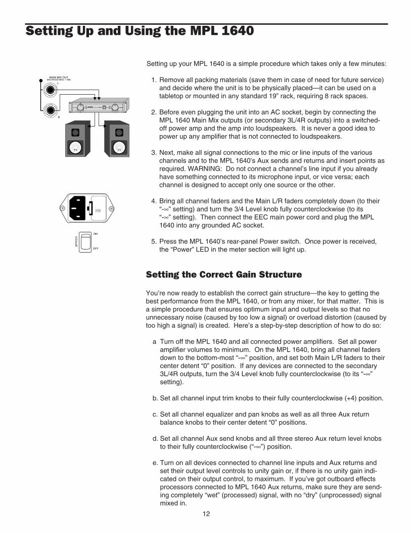
Setting up your MPL 1640 is a simple procedure which takes only a few minutes:
1. Remove all packing materials (save them in case of need for future service)and decide where the unit is to be physically placed—it can be used on atabletop or mounted in any standard 19” rack, requiring 8 rack spaces.
2. Before even plugging the unit into an AC socket, begin by connecting theMPL 1640 Main Mix outputs (or secondary 3L/4R outputs) into a switched-off power amp and the amp into loudspeakers. It is never a good idea topower up any amplifier that is not connected to loudspeakers.
3. Next, make all signal connections to the mic or line inputs of the variouschannels and to the MPL 1640’s Aux sends and returns and insert points asrequired. WARNING: Do not connect a channel’s line input if you alreadyhave something connected to its microphone input, or vice versa; eachchannel is designed to accept only one source or the other.
4. Bring all channel faders and the Main L/R faders completely down (to their“-∞” setting) and turn the 3/4 Level knob fully counterclockwise (to its“-∞” setting). Then connect the EEC main power cord and plug the MPL1640 into any grounded AC socket.
5. Press the MPL 1640’s rear-panel Power switch. Once power is received,the “Power” LED in the meter section will light up.
Setting the Correct Gain Structure
You’re now ready to establish the correct gain structure—the key to getting thebest performance from the MPL 1640, or from any mixer, for that matter. This isa simple procedure that ensures optimum input and output levels so that nounnecessary noise (caused by too low a signal) or overload distortion (caused bytoo high a signal) is created. Here’s a step-by-step description of how to do so:
a Turn off the MPL 1640 and all connected power amplifiers. Set all poweramplifier volumes to minimum. On the MPL 1640, bring all channel fadersdown to the bottom-most “-∞” position, and set both Main L/R faders to theircenter detent “0” position. If any devices are connected to the secondary3L/4R outputs, turn the 3/4 Level knob fully counterclockwise (to its “-∞”setting).
b. Set all channel input trim knobs to their fully counterclockwise (+4) position.
c. Set all channel equalizer and pan knobs as well as all three Aux returnbalance knobs to their center detent “0” positions.
d. Set all channel Aux send knobs and all three stereo Aux return level knobsto their fully counterclockwise (“-∞”) position.
e. Turn on all devices connected to channel line inputs and Aux returns andset their output level controls to unity gain or, if there is no unity gain indi-cated on their output control, to maximum. If you’ve got outboard effectsprocessors connected to MPL 1640 Aux returns, make sure they are send-ing completely “wet” (processed) signal, with no “dry” (unprocessed) signalmixed in.
Setting Up and Using the MPL 1640
MAIN MIX OUT(BALANCED 600Ω + 4dB)
L
R
SERVO - 240SAMSON
115
ON
OFF
POWER

13
Setting Up and Using the MPL 1640
f. If any condenser microphones are connected to the MPL 1640, turn on thePhantom switch.* Then turn on the MPL 1640—the Power LED in themeter section will light up. Finally, turn on the power amplifier.
g. Play an instrument connected to one of the MPL 1640’s line inputs** and,while doing so, raise the corresponding channel fader to the “0” position.You should see the segment meter begin to move—adjust the input trimcontrol for that channel so that the “0” segment lights frequently and the“+3” segment lights only occasionally. If the incoming signal seems too hoteven with the input channel trim all the way at its minimum (+4) setting, youmay need to lower the output level of the instrument, though this will rarelyoccur. Conversely, if the signal is too low even with the input channel trimall the way up, something's definitely wrong: in all likelihood, the connectingaudio cable is faulty.
h. Once you’ve set the optimum level in step (g) above, continue playing theinstrument and slowly raise the power amplifier volume until you get thelevel you want to hear.
i. Repeat step (g) above for each instrument connected to the MPL 1640channel line inputs.
j. The procedure for setting optimum microphone levels is virtually identical;sing or speak into the mic at the level you expect to use in performancewhile slowly raising the fader for that channel to its “0” position. Then adjustthe input trim control for that channel while watching the meter. You shouldexpect that microphone inputs will require rather more in the way of inputtrim boost than line inputs.
k. If you have any outboard signal processors connected to the Aux send andreturn jacks on the rear panel, follow this step. Because outboard effectsprocessors can sometimes be quite noisy, it’s particularly important to maxi-mize the amount of signal being sent to them via the MPL 1640 Aux sends.The idea is to drive these devices as hot as possible (short of overloadingthem) and to then use the corresponding Aux return level to carefully adjustthe amount of processed signal being blended with the dry signal. To setoptimum Aux send levels, use a channel that has already had its gain struc-ture adjusted in step (g) or (j) above. Turn all three Aux send knobs for thatchannel to their “0” (unity gain) position and then play the instrument (orsing into the microphone) connected to that channel. Adjust the input levelsof connected outboard effects processors so that their meter shows incom-ing signal normally in the 0 VU range (with just occasional higher excur-sions). Then it’s time to optimize the Aux return levels. While continuing toplay your instrument (or continuing to sing into the microphone), slowly raiseeach Aux return level control until you hear the desired amount ofprocessed signal added to the dry signal. For more information, see the“Using the Auxiliary Sends and Returns” section on page 20 of this manual.
* CAUTION: Before turning phantom power on, be sure to disconnect all non-microphone signal sources (such as direct injection boxes) from the XLRmic jacks (channels 1 - 10).
** If you're using an instrument such as electric guitar or bass, we recommendthat you connect it to the MPL 1640 with a direct injection box to ensure cor-rect impedance.

14
Setting Up and Using the MPL 1640
l. The gain structure is now correctly set—you’ve optimized the level of all sig-nals coming into and out of the MPL 1640, and the end result will be mini-mum noise and distortion and maximum clean sound. You’ll now find thatthe majority of your mixes can be accomplished with most channel fadersand both Main L/R faders at or near their 0 (unity gain) position and that thechannel peak LEDs rarely if ever light (remember, if they do light, it meansthat something is distorting!). If you need to make adjustments to the over-all level, use the volume control of your power amplifier.
Because this procedure sets the optimum input gain of all channels, it alsosets the correct gain structure when using the MPL 1640’s alternative Bus3/4 outputs. Following this procedure, if you opt to route a channel’s signalto the Bus 3/4 outputs (by pressing in that channel’s Bus switch), simply setthe main Bus 3/4 level knob to its detented 0 (unity gain) position for bestsignal-to-noise ratio.
If you encounter difficulty with any aspect of setting up or using your MPL 1640,you can call Samson Technical Support (516-932-1062) between 9 AM and5 PM EST.

Grounding Techniques
Hum and buzz are the biggest enemies you face when interconnecting a largenumber of different pieces of equipment to a central audio mixer. This isbecause each piece of equipment may operate at a marginally different voltage(this difference is called potential) and, when two devices at slightly differentpotential are physically connected with audio cabling, the end result can benasty, extraneous noise (mind you, connecting two devices at very differentpotential can result in a major electrical shock!).
However, there are several steps you can take to avoid grounding problems.First, assuming you have an isolated electrical circuit that can handle the electri-cal demands of your mixer and all connected audio equipment (these needs willusually be modest), you should always plug your mixer and all connected equip-ment into the same circuit. If possible, nothing else but this equipment should beconnected to that circuit. If you can’t do this, at least avoid plugging your mixerand audio equipment into the same circuit that is already powering things likeheavy machinery, air conditioners, heaters, refrigerators, washing machines,neon signs or fluorescent light fixtures. One particular culprit that will almost cer-tainly create problems is the standard light dimmer (the kind that uses siliconcontrolled rectifiers). Where low-level lighting is desired, use incandescent fix-tures with autotransformer-type dimmers (sometimes called Variacs) instead—these cost considerably more than the standard dimmer you’ll find at your localhardware store, but are well worth the extra expense.
Three-prong plugs (such as the one used by the MPL 1640) should always beused as is; don’t use adapters to lift the ground (unless you’re using a “starground network”—see below). If you hear hum or buzz from a device that usesa two-prong plug (or an external two-prong AC/DC adapter), you can try revers-ing the plug in the socket. If that doesn’t work, you may need to physicallyground that device’s chassis by connecting a wire (called a strap) from it to agrounded piece of metal such as rack ears. Some pieces of equipment have ascrew-type ground post to which the strap can be connected; if not, you canattach some kind of metallic binding post to the case itself. If you are using rack-mounted audio devices and are experiencing hum or buzz, there's a simple testto determine the source of the problem: while keeping all devices powered onand connected with audio cabling, physically remove each device, one by one,from the rack. If the hum disappears when a particular device is removed, you'llknow that that device is the culprit.
We also recommend that you use balanced audio cabling and connectors wher-ever possible. The MPL 1640 provides electronically balanced inputs for allchannel mic and line inputs as well as for its Main Mix outputs. The wiring dia-gram in the “Connecting The MPL 1640” section of this manual (page 10) showshow 1/4” TRS (Tip/Ring/Sleeve) connectors should be wired for use with theseinputs and outputs.
In addition, you can minimize possible interference by planning your audio, elec-trical, and computer cable runs so that they are as far apart from one another aspossible and so they don’t run parallel to one another. If they have to cross, tryto ensure that they do so at a 90° angle (that is, perpendicular to one another).In particular, try to keep audio cabling away from external AC/DC adapters.
15
Grounding Techniques
If you’re using the MPL 1640 in a fixed location such as a recording studio, youmay want to invest the time and money into creating a star ground network. Thisis by far the best technique for avoiding grounding problems. It involves using aformidable ground source such as a cold water pipe or a copper spike driven intothe earth. A thick grounding cable is connected to that source and is thenbrought to a central distribution point; from there, individual cables are connectedto each piece of equipment. This setup also requires that you lift the ground plugof all three-prong AC connectors, so there is the possibility of danger if it is doneincorrectly. We strongly recommend that you contract with a qualified profes-sional to carry out this or any kind of electrical work.
Another, less common problem you may encounter is that of oscillation (a ringingtone), which, apart from being annoying, is potentially dangerous to your speak-ers. This is generally caused either by poor outside wiring or by returning a sig-nal out of phase (most commonly from an outboard signal processor). If audibleoscillation occurs, try isolating each input signal (by muting all other inputs or byusing the PFL soloing function). If one signal alone is causing the problem, youshould be able to eliminate the oscillation by reversing that signal’s phase (manysignal processors have a switch that allows you to do this).
16
Using Bus 3/4
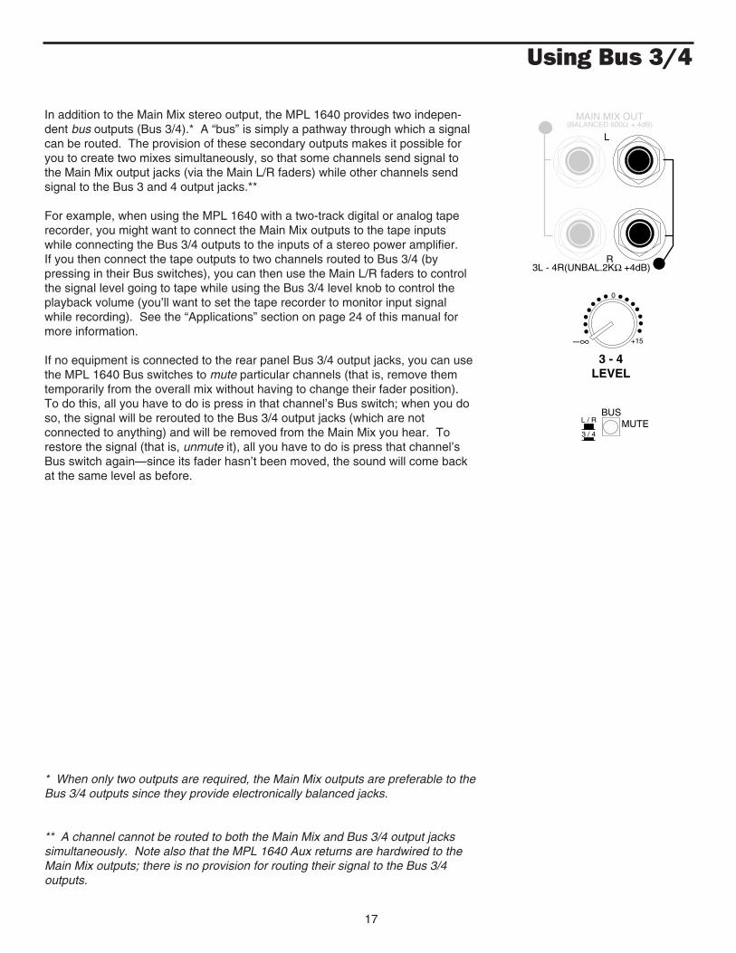
In addition to the Main Mix stereo output, the MPL 1640 provides two indepen-dent bus outputs (Bus 3/4).* A “bus” is simply a pathway through which a signalcan be routed. The provision of these secondary outputs makes it possible foryou to create two mixes simultaneously, so that some channels send signal tothe Main Mix output jacks (via the Main L/R faders) while other channels sendsignal to the Bus 3 and 4 output jacks.**
For example, when using the MPL 1640 with a two-track digital or analog taperecorder, you might want to connect the Main Mix outputs to the tape inputswhile connecting the Bus 3/4 outputs to the inputs of a stereo power amplifier.If you then connect the tape outputs to two channels routed to Bus 3/4 (bypressing in their Bus switches), you can then use the Main L/R faders to controlthe signal level going to tape while using the Bus 3/4 level knob to control theplayback volume (you’ll want to set the tape recorder to monitor input signalwhile recording). See the “Applications” section on page 24 of this manual formore information.
If no equipment is connected to the rear panel Bus 3/4 output jacks, you can usethe MPL 1640 Bus switches to mute particular channels (that is, remove themtemporarily from the overall mix without having to change their fader position).To do this, all you have to do is press in that channel’s Bus switch; when you doso, the signal will be rerouted to the Bus 3/4 output jacks (which are notconnected to anything) and will be removed from the Main Mix you hear. Torestore the signal (that is, unmute it), all you have to do is press that channel’sBus switch again—since its fader hasn’t been moved, the sound will come backat the same level as before.
* When only two outputs are required, the Main Mix outputs are preferable to theBus 3/4 outputs since they provide electronically balanced jacks.
** A channel cannot be routed to both the Main Mix and Bus 3/4 output jackssimultaneously. Note also that the MPL 1640 Aux returns are hardwired to theMain Mix outputs; there is no provision for routing their signal to the Bus 3/4outputs.
17
MAIN MIX OUT(BALANCED 600Ω + 4dB)
L
R3L - 4R(UNBAL.2KΩ +4dB)
3 - 4LEVEL
−∞ +15
0
BUS
3 / 4
L / R MUTE

18
Using Pan
The final Main output of the MPL 1640 is stereo—that is, there are two discreteMain Mix output jacks, labeled “left” and “right,” which will normally route signal(via a power amplifier) to two discrete speakers.* Because of this, you will usual-ly be working with a stereo field that ranges from hard left to hard right. The Pancontrol in each channel allows you to place each individual sound at any pointwithin this left-right field, while keeping the overall level constant.
You can use stereo panning creatively in a variety of ways: For example, youmight want to have guitars coming from one speaker and keyboards from anoth-er, or you might use panning to “spread” the signal from a piano miked with twomicrophones—one over the bass notes (panned left) and the other over the tre-ble notes (panned right). By turning a Pan knob while a signal is present, thesound appears to move in space (a process known as dynamic panning)—thiscan be particularly effective when applied to sound effects.
In live performance, you may want to resist the temptation to pan anything com-pletely hard left or right, since some members of the audience not seated in thecenter of the venue may miss some signal altogether. In these circumstances,you’re best to use modest panning, with signals routed no further than the 9o’clock and 3 o’clock positions.
In the stereo Auxiliary return section, the Balance control allows you to adjust therelative levels of the signals arriving at the left and right inputs. In Aux returnswhere both inputs are connected, the left signal is automatically panned hard leftand the right signal is automatically panned hard right. The Balance knob con-trols the relative levels of the paired input signals. When the knob is placed at itscenter (detented) position, both the left and right signals are at equal strength.When moved left of center, the left input signal remains the same but the rightinput signal is attenuated; when the knob is moved right of center, the right inputsignal remains the same but the left input signal is attenuated. When placedfully counterclockwise, only the left input is heard (panned hard left); whenplaced fully clockwise, only the right input is heard (panned hard right).
If you connect different monophonic devices (such as effects processors) to boththe left and right inputs of an Aux return, you can use the Aux Balance control toblend the relative contribution of each. If you turn the Balance knob fully coun-terclockwise, you’ll hear only the device connected to the left Aux input; if youturn it fully clockwise, you’ll hear only the device connected to the right Aux input.For more information, see the “Using the Auxiliary Sends and Returns” sectionon page 20 of this manual.
* You can, of course, also use the MPL 1640 monophonically—simply route thesame signal to both the left and right outputs.
RBALANCE
L
RPAN
L

19
Using Equalization
One of the most exciting aspects to using a mixer such as the MPL 1640 is hav-ing the ability to shape a sound, using a process called equalization. But thereare few areas of sound engineering more misunderstood than equalization, and,just as good EQ can really help a sound, bad EQ can really hurt it, so read on...
Every naturally occurring sound consists of a broad range of pitches, or frequen-cies, combined together in a unique way. This blend is what gives every soundits distinctive tonal color. The EQ section in a mixer allows you to alter a soundby boosting or attenuating specific frequency areas. The MPL 1640 providesindependent three-band equalization controls for each of its sixteen channels.The “High” knob affects frequencies in the 10 kHz area; the “Mid” knob affectsfrequencies in the 800 Hz area; and the “Low” knob affects frequencies in the80 Hz area. Each EQ knob is labeled with the maximum amount of cut or boostprovided (±15 dB in the case of high and low frequencies, and ±12 dB in thecase of the mid frequency).
We provided these particular frequency areas because they have maximumimpact on musical signals—that’s why they are sometimes known as “sweetspots.” When an EQ knob is in its center detented position (“0”), it is having noeffect. When it is moved right of center, the particular frequency area is beingboosted; when it is moved left of center, the frequency area is being attenuated.The high and low EQ controls employ what is known as a shelving curve (wherefrequencies either above or below the specified area are affected, respectively)while the mid frequency control employs what is known as a bell curve (wherefrequencies both above and below the specified area are affected).
In most instances, the best way to approach equalization is to think in terms ofwhich frequency areas you need to attenuate, as opposed to which ones youneed to boost (boosting a frequency area also has the effect of boosting theoverall signal; too much EQ boost can actually cause overload—with the accom-panying Peak LED warning!). Be aware of the phenomenon of masking, whereloud sounds in one frequency range obscure softer sounds in the same range;by cutting EQ “notches” in a loud signal, you can actually make room for a softerone to shine through. And try not to think of EQ as a miracle worker—no amountof equalization can put a singer in tune or remove the distortion from an over-loaded input signal! The key is to get the signal right in the first place, by usingcorrect gain structure and mic placement.
Although the specific EQ you will apply to a signal is very much a matter ofpersonal taste, here are a few general suggestions: Boosting the low frequencyof instruments such as bass drums or bass guitar will add warmth and make thesound “fatter”; conversely, you may want to attenuate the low frequency compo-nent of instruments such as cymbals, high-hats, and shakers so as to “thin” themout. The mid-range control is particularly effective for vocals—attenuating it cangive a vocal performance more of an “FM-radio” feel, while boosting it can help avocal cut through dense instrumentation. Be careful not to boost high frequen-cies too much or you risk adding hiss to the signal, though just a touch can helpadd “shimmer” to an acoustic guitar, ride cymbal, or high-hat. Finally, becauseboth the high and low EQ settings are shelving controls, you can use them toreduce hiss (by attenuating high frequencies) or rumble (by attenuating lowfrequencies).
-15 +15HIGH
0
-12 +12MID
0
-15 +15LOW
0

20
Using the Auxiliary Sends and Returns
The MPL 1640’s system of Auxiliary sends allow you to combine the signal frommultiple channels and send the resulting mix to external devices such as effectsprocessors. When an Aux send knob is at the “0” position, the signal is routedwith unity gain (that is, no boost or attenuation). As it is turned clockwise fromthe 0 position, the signal is boosted; as it is turned counterclockwise from the 0position, it is attenuated. Auxiliary send 1 is always pre-fader; that is, the level ofthe signal sent through this knob is determined solely by the input trim and isunaffected by the channel fader position or EQ settings; for this reason, it is opti-mum for applications like headphone cueing or sending a feed to onstage moni-tors—both situations where you want the performer’s mix to be independent ofthe main mix. You can also use Aux 1 to route signal to a reverb processor inorder to create a distancing kind of effect where the “wet” reverb signal remainsconstant even as the “dry” source signal fades away. Aux sends 2 and 3 arepost-fader; that is, the level of the signal is determined by the input trim, the EQsettings, and the position of the channel fader. Here, raising or lowering theinput level of the channel will affect the send level as well.
The MPL 1640 also provides three stereo Auxiliary returns. These allow you toreturn signal from outboard devices, either in stereo pairs or monophonically(many popular effects processors provide a single mono input but have a pair ofstereo outputs). In practice, you’ll probably want to use the Auxiliary returns tobring in signal from connected effects processors. If the effects processors havestereo outputs, they should be connected to both the left and right Auxiliaryreturn inputs so that their stereo integrity is retained. If they have mono outputs,you can route them to either the left or right inputs and then use the Auxiliaryreturn Balance control to adjust the relative level of each paired signal. In thisway, you can actually connect up to six monophonic devices to the MPL 1640’sAux return section. Note that, when only the left input of an Aux return is con-nected, its Balance knob functions as a constant level Pan control, allowing youto continuously place the incoming signal anywhere in the left-right stereo field.
Note that the MPL 1640 Aux returns are hardwired to the Main Mix outputs; thereis no provision for routing their signal to the Bus 3/4 outputs.
+10AUX 1
0
−∞
+10AUX 2
0
−∞
+10AUX 3
0
−∞
+20RETURN 1 LEVEL
0
−∞
+20
0
−∞RETURN 2 LEVEL
+20
0
−∞RETURN 3 LEVEL
RBALANCE
L
RBALANCE
L
RBALANCE
L

21
Using Channel Inserts
In addition to using Auxiliary sends and returns to access outboard devices, theMPL 1640 also provides channel inserts for input channels 1 - 12 as well as forthe Main Mix and Bus 3/4 outputs.
Channel inserts should be used when you want to affect just one signal, asopposed to signal from several channels—most often, this will be for dynamicprocessing purposes (such as outboard equalization, compression/limiting, ornoise gating). Channel insert signal is returned just before the channel fader; forthis reason, the output level of external devices connected to MPL 1640 channelinserts should always be set to unity gain. You can also use the channel insertsends as post-eq (but pre-fader) direct outputs, if you need to route a singlemonophonic signal to an external device such as a tape deck.
The Main Mix and Bus 3/4 inserts are useful when you want to effect the entiremix with a device such as a room equalizer or stereo compressor/limiter. TheMain Mix insert signal is returned just before the Main L/R faders, and the Bus3/4 insert signal is returned just before the Bus 3/4 level control.
All rear panel insert jacks accept 1/4" TRS plugs, with the ring carrying the sendsignal and the tip carrying the return signal; this will normally be connected to aY-cable (see the “Connecting The MPL 1640” section on page 10 for a wiringdiagram). This configuration is sometimes known as an “effects loop,” since thesignal is sent and returned over the same cable.
If nothing is plugged into insert jacks, they have no effect—but if you connectthem to a passive device like a patchbay, you’ll need to normal (permanentlyconnect) or half-normal (connection is made unless overriden by a patch cord)the send to the return.
3L - 4RMAIN MIX
R
L
BUS INSERT
CH 1CH 2CH 3CH 4CH 5CH 6CH 7CH 8CH 9CH 10CH 11CH 12
CHANNEL INSERT (TIP RETURN - RING SEND)

22
Using PFL Solo
The MPL 1640 provides PFL (Pre-Fade Listen) solo switches for each of its six-teen input channels. The main function of PFL is to allow you to check that asignal is actually arriving at a particular input. When a PFL(solo) switch ispressed, the pre-fader (but post-EQ) signal of that channel alone is routed to theheadphone output and to the meter. The Main Mix outputs are not interruptedduring a PFL solo, so you can press any Solo switch even during recording orlive performance without affecting the main signal flow. This also makes it possi-ble for you to correctly cue up a tape or CD before bringing it into the main mix.
Be aware, however, that PFL solo does not allow you to hear a signal in context.For one thing, the soloed signal is monitored pre-fader, so, depending upon thecurrent position of the channel fader and input trim, it may sound considerablylouder or softer than it actually is in the Main Mix. Secondly, the soloed signal isalways monitored monophonically—even if it’s actually panned off to one side.Finally, the PFL soloed signal appears without any outboard signal processingbeing applied via the Aux sends and returns (however, any signal processingbeing applied by a channel insert routing is heard). Note that there is no provi-sion for soloing signal returning to the MPL 1640 Aux returns.
The meter display allows you to see at a glance whether or not a signal iscurrently being soloed—the bottom left LED (labeled “PFL”) lights steadily redwhenever one or more channels is soloed. If you are monitoring over head-phones and you don’t hear a sound from the MPL 1640 when everything elseseems to be functioning correctly (i.e. meter is moving, connectors are pluggedin, etc.), a likely reason might be that one or more of the channel PFL (solo)switches may be accidentally pressed in—so check the PFL LED in the metersection before panicking!
PFL
ON
OFF
STERE0 PFL
LEFT
RIGHT
PFL PHANTOM POWER
-20 -10 -6 -3 0 +3 +6
-20 -10 -6 -3 0 +3 +6

Changing the MPL 1640 from Rack-mount to Tabletop
The diagrams below show the steps required to convert the MPL 1640 from rack-mount to tabletop usage or vice-versa.CAUTION: These servicing instructions are for use by qualified personnel only. Refer all servicing to qualified service personnel.
23
REMOVE COVERPLATE SCREWS
RACKMOUNT ARRANGEMENT(REAR FACING JACKFIELD)
RACKMOUNT EAR JACKFIELD 6 SCREWS
COVERPLATE 3 SCREWS
REMOVEARMREST
(4 SCREWS)
TABLETOP ARRANGEMENT
REMOVE SCREWS
JACKFIELD6 SCREWS
COVERPLATE 3 SCREWS

24
Applications
Here are four suggested applications for the MPL 1640; bear in mind that your particular circumstance may dictatechanges in these suggested signal connections and routings.
Application 1 - Using the MPL 1640 as a main live mixer
The main connections here involve routing the MPL 1640’s Main Mix output to the input of a power amplifier, and, fromthere, to PA speakers. Microphones and line level signals are connected to various channel inputs. Signal processorsare connected to Aux sends and returns and to channel inserts as required. The Main Mix inserts are connected to aroom equalizer. Finally, a submix from Aux send 1 is connected to the input of a second power amplifier driving onstagemonitor speakers so that performers can receive a monitor mix independent of the house mix.
12
3
12
3
12
3
12
3
12
3
CH 1CH 2CH 3CH 4CH 5
CH 1CH 2CH 3CH 4CH 5CH 6CH 7CH 8CH 9CH 10CH 11CH 12CH 13CH 14CH 15CH 16
ON
OFF
12
3
CH 6
12
3
CH 7
12
3
CH 8
12
3
CH 9
12
3
CH 10CH 11CH 12CH 13CH 14CH 15CH 16
115
CAUTION
RISK OF ELECTRIC SHOCKDO NOT OPEN
!
ON
OFF
~115V /230V50/60Hz 42W
MAIN MIX OUT(BALANCED 600Ω + 4dB)
POWER
PHANTOM
SERIAL
NUMBER
AVIS:RISQUE DE CHOC ELECTRIQUE
NE PAS OUVRIR.DO NOT EXPOSE THIS EQUIPMENT
TO RAIN OR MOISTURE.
XLR
1 GND2 +3 -
MPL 1640 16 CHANNELAUDIO MIXER
TIP RING SLEEVE
TIP +RING -
SLEEVE GNDASSEMBLED IN R.O.K. SAMSON TECHNOLOGIES CORP., NEW YORK, U.S.A.
SAMSONL
CHANNEL INSERT (TIP RETURN - RING SEND)
AUX 1AUX 23L - 4RMAIN MIX
R
L
AUX 3
AUX 3 AUX 2 AUX 1AUX RETURN (UNBAL.2KΩ + 4dB)
RRR L L L
(BALANCED - 50dB TO + 4dB)MIC INPUT
R3L - 4R(UNBAL.2KΩ +4dB)
BUS INSERT AUX OUT(UNBAL.2KΩ +4dB) LINE INPUT (BALANCED 10 KΩ - 40dB TO + 4dB)
SERVO - 240SAMSON
SERVO - 240SAMSON
20Hz 25Hz 31.5Hz 40Hz 50Hz 63Hz 80Hz 100Hz 125Hz 160Hz 200Hz 250Hz 315Hz 400Hz 500Hz 630Hz 800Hz 1Khz 1.25Khz 1.6Khz 2Khz 2.5Khz 3.15Khz 4Khz 5Khz 6.3Khz 8Khz 10Khz 12.5Khz 16Khz 20Khz
20Khz16Khz12.5Khz10Khz8Khz6.3Khz5Khz4Khz3.15Khz2.5Khz2Khz1.6Khz1.25Khz1Khz800Hz630Hz500Hz400Hz315Hz250Hz200Hz160Hz125Hz100Hz80Hz63Hz50Hz40Hz31.5Hz25Hz20Hz
+15db
0
-15db
0
+15db
-15db -15db
+15db
0
+15db
-15db
0
SAMSON1/3 OCTAVE DUAL 31 BAND GRAPHIC EQUALIZERE62
POWER
BYPASS
BYPASS
PEAK
PEAK
AMPLIFIER
GRAPHIC EQUALIZER
SIGNAL PROCESSOR
STEREO AMPLIFIER
SIGNAL PROCESSOR

25
Applications
Application 2 - Using the MPL 1640 as an onstage monitor mixer
Here, the MPL 1640 is receiving signal into its line inputs from the direct channel outputs of a main live mixer. Its MainMix output is connected to an amplifier and onstage monitors, and the Main Mix inserts are connected to a graphicequalizer. This allows the overall mix to be adjusted in order to eliminate feedback and ringing problems.
12
3
12
3
12
3
12
3
12
3
CH 1CH 2CH 3CH 4CH 5
CH 1CH 2CH 3CH 4CH 5CH 6CH 7CH 8CH 9CH 10CH 11CH 12CH 13CH 14CH 15CH 16
ON
OFF
12
3
CH 6
12
3
CH 7
12
3
CH 8
12
3
CH 9
12
3
CH 10CH 11CH 12CH 13CH 14CH 15CH 16
115
CAUTION
RISK OF ELECTRIC SHOCKDO NOT OPEN
!
ON
OFF
~115V /230V50/60Hz 42W
MAIN MIX OUT(BALANCED 600Ω + 4dB)
POWER
PHANTOM
SERIAL
NUMBER
AVIS:RISQUE DE CHOC ELECTRIQUE
NE PAS OUVRIR.DO NOT EXPOSE THIS EQUIPMENT
TO RAIN OR MOISTURE.
XLR
1 GND2 +3 -
MPL 1640 16 CHANNELAUDIO MIXER
TIP RING SLEEVE
TIP +RING -
SLEEVE GNDASSEMBLED IN R.O.K. SAMSON TECHNOLOGIES CORP., NEW YORK, U.S.A.
SAMSONL
CHANNEL INSERT (TIP RETURN - RING SEND)
AUX 1AUX 23L - 4RMAIN MIX
R
L
AUX 3
AUX 3 AUX 2 AUX 1AUX RETURN (UNBAL.2KΩ + 4dB)
RRR L L L
(BALANCED - 50dB TO + 4dB)MIC INPUT
R3L - 4R(UNBAL.2KΩ +4dB)
BUS INSERT AUX OUT(UNBAL.2KΩ +4dB) LINE INPUT (BALANCED 10 KΩ - 40dB TO + 4dB)
SERVO - 240SAMSON
SAMSON
MPL2242
MMPL2242
MPL2242
STEREO AMP
20Hz 25Hz 31.5Hz 40Hz 50Hz 63Hz 80Hz 100Hz 125Hz 160Hz 200Hz 250Hz 315Hz 400Hz 500Hz 630Hz 800Hz 1Khz 1.25Khz 1.6Khz 2Khz 2.5Khz 3.15Khz 4Khz 5Khz 6.3Khz 8Khz 10Khz 12.5Khz 16Khz 20Khz
20Khz16Khz12.5Khz10Khz8Khz6.3Khz5Khz4Khz3.15Khz2.5Khz2Khz1.6Khz1.25Khz1Khz800Hz630Hz500Hz400Hz315Hz250Hz200Hz160Hz125Hz100Hz80Hz63Hz50Hz40Hz31.5Hz25Hz20Hz
+15db
0
-15db
0
+15db
-15db -15db
+15db
0
+15db
-15db
0
SAMSON1/3 OCTAVE DUAL 31 BAND GRAPHIC EQUALIZERE62
POWER
BYPASS
BYPASS
PEAK
PEAK
GRAPHIC EQUALIZER

26
Applications
Application 3 - Using the MPL 1640 as a keyboard submixer
Here, various keyboards and MIDI tone generators are connected to various line inputs of the MPL 1640. Signal proces-sors are connected to Aux sends and returns and to channel inserts as required. The Main Mix output is routed to stereoinput channels of a live performance or recording mixing console, with the performer having complete control over theblend of signals being provided to the sound engineer.
12
3
12
3
12
3
12
3
12
3
CH 1CH 2CH 3CH 4CH 5
CH 1CH 2CH 3CH 4CH 5CH 6CH 7CH 8CH 9CH 10CH 11CH 12CH 13CH 14CH 15CH 16
ON
OFF
12
3
CH 6
12
3
CH 7
12
3
CH 8
12
3
CH 9
12
3
CH 10CH 11CH 12CH 13CH 14CH 15CH 16
115
CAUTION
RISK OF ELECTRIC SHOCKDO NOT OPEN
!
ON
OFF
~115V /230V50/60Hz 42W
MAIN MIX OUT(BALANCED 600Ω + 4dB)
POWER
PHANTOM
SERIAL
NUMBER
AVIS:RISQUE DE CHOC ELECTRIQUE
NE PAS OUVRIR.DO NOT EXPOSE THIS EQUIPMENT
TO RAIN OR MOISTURE.
XLR
1 GND2 +3 -
MPL 1640 16 CHANNELAUDIO MIXER
TIP RING SLEEVE
TIP +RING -
SLEEVE GNDASSEMBLED IN R.O.K. SAMSON TECHNOLOGIES CORP., NEW YORK, U.S.A.
SAMSONL
CHANNEL INSERT (TIP RETURN - RING SEND)
AUX 1AUX 23L - 4RMAIN MIX
R
L
AUX 3
AUX 3 AUX 2 AUX 1AUX RETURN (UNBAL.2KΩ + 4dB)
RRR L L L
(BALANCED - 50dB TO + 4dB)MIC INPUT
R3L - 4R(UNBAL.2KΩ +4dB)
BUS INSERT AUX OUT(UNBAL.2KΩ +4dB) LINE INPUT (BALANCED 10 KΩ - 40dB TO + 4dB)
SIGNAL PROCESSOR
SAMSON
MPL2242
MMPL2242
MPL2242
SIGNAL PROCESSOR
MIDI TONE GENERATOR
MIDI TONE GENERATOR
27
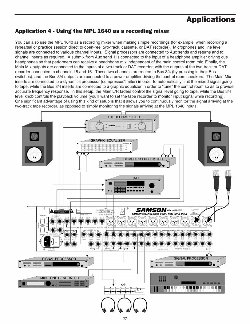
ApplicationsApplication 4 - Using the MPL 1640 as a recording mixer
You can also use the MPL 1640 as a recording mixer when making simple recordings (for example, when recording arehearsal or practice session direct to open-reel two-track, cassette, or DAT recorder). Microphones and line levelsignals are connected to various channel inputs. Signal processors are connected to Aux sends and returns and tochannel inserts as required. A submix from Aux send 1 is connected to the input of a headphone amplifier driving cueheadphones so that performers can receive a headphone mix independent of the main control room mix. Finally, theMain Mix outputs are connected to the inputs of a two-track or DAT recorder, with the outputs of the two-track or DATrecorder connected to channels 15 and 16. These two channels are routed to Bus 3/4 (by pressing in their Busswitches), and the Bus 3/4 outputs are connected to a power amplifier driving the control room speakers. The Main Mixinserts are connected to a dynamics processor (compressor/limiter) in order to automatically limit the mixed signal goingto tape, while the Bus 3/4 inserts are connected to a graphic equalizer in order to “tune” the control room so as to provideaccurate frequency response. In this setup, the Main L/R faders control the signal level going to tape, while the Bus 3/4level knob controls the playback volume (you’ll want to set the tape recorder to monitor input signal while recording).One significant advantage of using this kind of setup is that it allows you to continuously monitor the signal arriving at thetwo-track tape recorder, as opposed to simply monitoring the signals arriving at the MPL 1640 inputs.
12
3
12
3
12
3
12
3
12
3
CH 1CH 2CH 3CH 4CH 5
CH 1CH 2CH 3CH 4CH 5CH 6CH 7CH 8CH 9CH 10CH 11CH 12CH 13CH 14CH 15CH 16
ON
OFF
12
3
CH 6
12
3
CH 7
12
3
CH 8
12
3
CH 9
12
3
CH 10CH 11CH 12CH 13CH 14CH 15CH 16
115
CAUTION
RISK OF ELECTRIC SHOCKDO NOT OPEN
!
ON
OFF
~115V /230V50/60Hz 42W
MAIN MIX OUT(BALANCED 600Ω + 4dB)
POWER
PHANTOM
SERIAL
NUMBER
AVIS:RISQUE DE CHOC ELECTRIQUE
NE PAS OUVRIR.DO NOT EXPOSE THIS EQUIPMENT
TO RAIN OR MOISTURE.
XLR
1 GND2 +3 -
MPL 1640 16 CHANNELAUDIO MIXER
TIP RING SLEEVE
TIP +RING -
SLEEVE GNDASSEMBLED IN R.O.K. SAMSON TECHNOLOGIES CORP., NEW YORK, U.S.A.
SAMSONL
CHANNEL INSERT (TIP RETURN - RING SEND)
AUX 1AUX 23L - 4RMAIN MIX
R
L
AUX 3
AUX 3 AUX 2 AUX 1AUX RETURN (UNBAL.2KΩ + 4dB)
RRR L L L
(BALANCED - 50dB TO + 4dB)MIC INPUT
R3L - 4R(UNBAL.2KΩ +4dB)
BUSS INSERT AUX OUT(UNBAL.2KΩ +4dB) LINE INPUT (BALANCED 10 KΩ - 40dB TO + 4dB)
SIGNAL PROCESSORSIGNAL PROCESSOR
MIDI TONE GENERATOR
SERVO - 240SAMSON
STEREO AMPLIFIER
DAT
COMPRESSOR / LIMITER
Q5 HEADPHONE AMPLIFIER
Q5
20Hz 25Hz 31.5Hz 40Hz 50Hz 63Hz 80Hz 100Hz 125Hz 160Hz 200Hz 250Hz 315Hz 400Hz 500Hz 630Hz 800Hz 1Khz 1.25Khz 1.6Khz 2Khz 2.5Khz 3.15Khz 4Khz 5Khz 6.3Khz 8Khz 10Khz 12.5Khz 16Khz 20Khz
20Khz16Khz12.5Khz10Khz8Khz6.3Khz5Khz4Khz3.15Khz2.5Khz2Khz1.6Khz1.25Khz1Khz800Hz630Hz500Hz400Hz315Hz250Hz200Hz160Hz125Hz100Hz80Hz63Hz50Hz40Hz31.5Hz25Hz20Hz
+15db
0
-15db
0
+15db
-15db -15db
+15db
0
+15db
-15db
0
SAMSON1/3 OCTAVE DUAL 31 BAND GRAPHIC EQUALIZERE62
POWER
BYPASS
BYPASS
PEAK
PEAK
GRAPHIC EQUALIZER

Appendix A: Changing the MPL 1640 Voltage
28
Note that the fuse sled carries two fuses—one for 115 volt operation (actually 105 - 120 volts) and another for 230 voltoperation (actually 220 - 240 volts). The position of the two fuses in the sled as well as the fuse ratings must bemaintained for adequate protection. Fuse ratings for the MPL 1640 are: 1 amp for 115 VAC and .5 amp for 230 VAC.
Following are step-by-step instructions for changing the mains voltage of the MPL 1640. WARNING: Before carrying out this operation, remove the power cord!
110
110220
110220110220
1: Insert a small screwdriv-er into the hook beneath thefuse sled and pull it out fromits retaining clip. Hold thehook with your fingers andgently pull the sled out.
3: Use a small pair ofneedlenose pliers togently pull out themains jumper.
2: Remove fuse sled.
4: Use the needlenose pliers to turn themains jumper upside down so that theother voltage value is right side up, thenreinsert the mains jumper. Reinsert thefuse sled by gently pushing it back inuntil you hear a click and snap the hookback beneath its retaining clip.
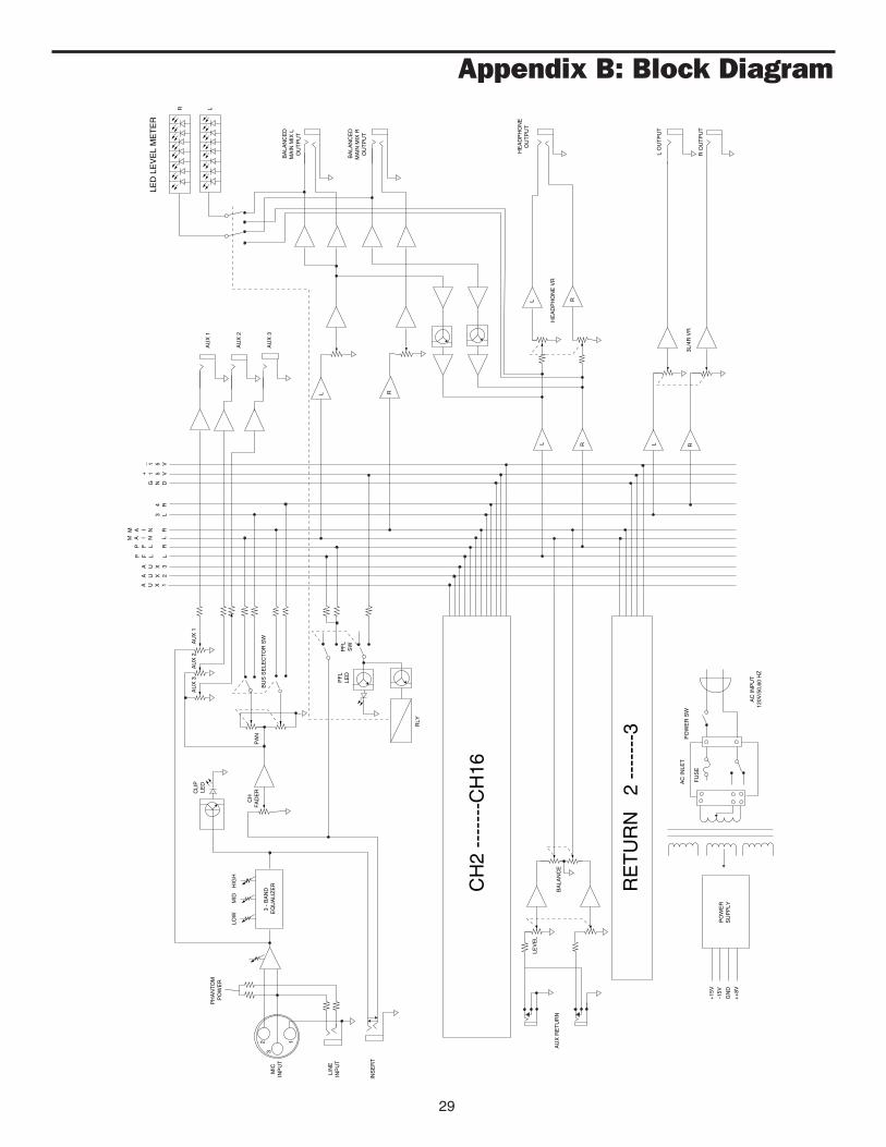
Appendix B: Block Diagram
29
PH
AN
TO
M
PO
WE
R
MIC
INP
UT
LIN
EIN
PU
T
3 -
BA
ND
EQ
UA
LIZ
ER
LOW
MID
HIG
H
INS
ER
T
123
PA
NC
HF
AD
ERC
LIP
LED
AU
X 3
AU
X 2
AU
X 1
BU
S S
ELE
CT
OR
SW
RLY
LEV
EL
BA
LAN
CE
RLL R
RL
L O
UT
PU
T
R O
UT
PU
T
HE
AD
PH
ON
EO
UT
PU
T
BA
LAN
CE
DM
AIN
MIX
RO
UT
PU
T
BA
LAN
CE
DM
AIN
MIX
LO
UT
PU
T
LED
LE
VE
L M
ET
ER
R LA
UX
1
AU
X 2
AU
X 3
L R
HE
AD
PH
ON
E V
R
3L/4
R V
R
CH
2 --
----
-CH
16
RE
TU
RN
2
----
---3
PO
WE
RS
UP
PLY
+15
V-1
5V
GN
D
++
8V
PO
WE
R S
WA
C IN
LET
FU
SE
AC
INP
UT
120V
/50,
60 H
Z
A U X 1
A U X 2
A U X 3
P F L L
P F L R
M A I N L
M A I N R3 L
4 R
G N D
+ 1 5 V
_ 1 5 V
PF
LLE
DP
FL
SW
AU
X R
ET
UR
N

Specifications
Normal Limit
Frequency ResponseMic/Line to Main ± 1 dB 10 Hz - 45 kHz 20 Hz - 20 kHz(Trim @ min, output @ 0 dB,In/Out fader @ center position)
Aux Return to Main ± 1 dB 11 Hz - 26 kHz 20 Hz - 20 kHz(Return VR @ “0” position,Main fader @ center position,output @ 0 dB)
Total Harmonic Distortion(Output 600 ohm balanced)
Line to Main Out 0.016% 0.05%(Trim @ min, output @ 0 dB,In/Out fader @ center position,1 kHz, with 80 kHz LPF)
Line to Aux Send 0.016% 0.05%
Equivalent Input Noise(“A” filter on, input shorted)
Mic (Ch 1 - Ch 16) -128 dB -128 dBLine (Ch 1 - Ch 16) -110 dB -110 dB
Maximum Voltage Gain (± 5 dB)Ch Input (1 kHz, output 600 ohm load, balanced)
Mic to Main L/R 84 dBLine to Main L/R 74 dBAux Return to Main L/R 34 dB
Ch Input (1 kHz, output unbalanced)Mic to 3L/4R 84 dBLine to 3L/4R 74 dBMic to Aux Send 79 dBLine to Aux Send 69 dB
Residual Noise(1 kHz, with 30 kHz LPF on, all VR @ min, all faders down)
L/R Main Out 95 dB 90 dB3L/4R Out 89 dB 85 dBAux Sends 82 dB 76 dBH/P Out 84 dB 76 dB
Crosstalk (@ 1 kHz, with 30 kHz LPF on)Ch vs. Ch 76 dB 70 dBInput vs. Output 72 dB 62 dB
Peak LED Sensitivity (before clipping) -5 dB -5 dB ± 2 dB
Headphone Output (95 ohm load) 200 mW More than 2.2V(150 mW)
Level LED Display(@ +4 dB output, balanced 600 ohm) 0 dB 0 dB ± 3 dB
Phantom Power (± 3 V) + 48 V
30

31
Specifications
Maximum Input Level (±3 dB)Ch Input Mic +14 dBCh Input Line +24 dB
Channel fader range +15 dB to -80 dB
Aux send gain range +10 dB to -75 dB
Input Channel Equalization (± 2 dB)High (10 kHz) ± 15 dBMid (800 Hz) ± 12 dBLow (80 Hz) ± 15 dB
Dimensions (W x D x H) 482 x 373 x 112 mm19 x 14.7 x 4.4 in
Weight 7 kg • 15.4 lbs
Power Requirements 120 VAC 60 Hz 230/240 VAC 50/60 Hz
Power Consumption 42 w 42 w

Produced by On The Right Wavelength for Samson Technologies Corp.
Copyright 1994, Samson Technologies Corp.
Printed August 1994
Samson Technologies Corp.262 Duffy AvenueHicksville, NY 11801Phone: 516-932-1062 Fax: 516-932-3815


![DançA Lent[1]](https://img.dokumen.tips/doc/110x75/559e701f1a28ab37428b466c/danca-lent1.jpg)