Embed Size (px)
Citation preview

Draw Guide
Chapter 4 Changing Object Attributes
Copyright
This document is Copyright © 2011–2015 by the LibreOffice Documentation Team. Contributors are listed below. You may distribute or modify it under the terms of either the GNU General Public License (http://www.gnu.org/licenses/gpl.html), version 3 or later, or the Creative Commons Attribution License (http://creativecommons.org/licenses/by/4.0/), version 4.0 or later.
All trademarks within this guide belong to their legitimate owners.
ContributorsPeter Schofield Martin Fox Jean Hollis WeberJohn A Smith Hazel Russman John Cleland
FeedbackPlease direct any comments or suggestions about this document to the Documentation Team’s mailing list: [email protected]
Note: Everything you send to a mailing list, including your email address and any other personal information that is written in the message, is publicly archived and cannot be deleted.
AcknowledgmentsThis chapter is based on an original French document written for OpenOffice.org 1.x by Michel Pinquier (translated into English by Alex Thurgood) and previous content revised by Jim Taylor. The chapter was revised for OpenOffice.org 2.0 by Linda Worthington, Daniel Carrera, Jean Hollis Weber, and Agnes Belzunce, and later translated into German by Wolfgang Uhlig. The German revisions were then translated into English and revised for OpenOffice.org 3.3 and LibreOffice 3.3 by Martin Fox. Other contributors included Peter Hillier-Brook, Hazel Russman, Gary Schnabl, and Claire Wood.
Publication date and software versionPublished 22 January 2015. Based on LibreOffice 4.3.
Note for Mac users
Some keystrokes and menu items are different on a Mac from those used in Windows and Linux. The table below gives some common substitutions for the instructions in this chapter. For a more detailed list, see the application Help.
Windows or Linux Mac equivalent Effect
Tools > Options menu selection
LibreOffice > Preferences Access setup options
Right-click Control+click or right-click depending on computer setup
Opens a context menu
Ctrl (Control) ⌘ (Command) Used with other keys
F5 Shift+⌘+F5 Opens the Navigator
F11 ⌘+T Opens the Styles and Formatting window
Documentation for LibreOffice is available at http://www.libreoffice.org/get-help/documentation
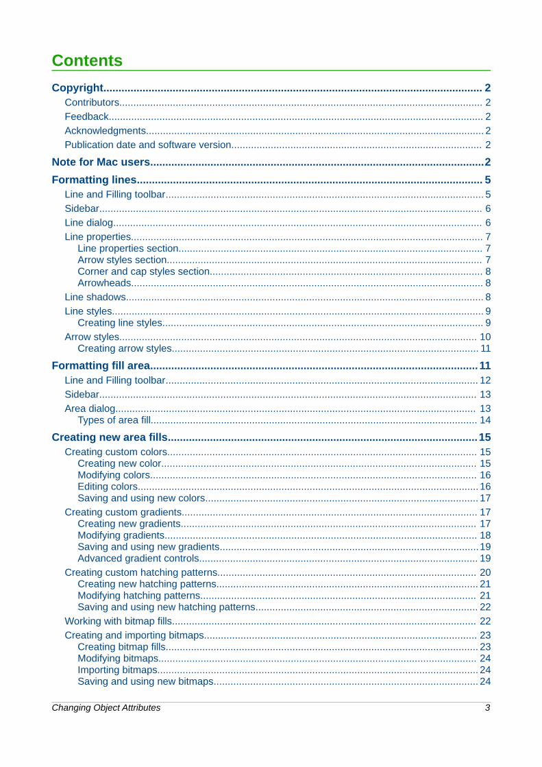
Contents
Copyright.............................................................................................................................. 2Contributors................................................................................................................................. 2
Feedback..................................................................................................................................... 2
Acknowledgments........................................................................................................................ 2
Publication date and software version......................................................................................... 2
Note for Mac users...............................................................................................................2
Formatting lines................................................................................................................... 5Line and Filling toolbar................................................................................................................. 5
Sidebar........................................................................................................................................ 6
Line dialog................................................................................................................................... 6
Line properties............................................................................................................................. 7Line properties section............................................................................................................ 7Arrow styles section................................................................................................................ 7Corner and cap styles section................................................................................................. 8Arrowheads............................................................................................................................. 8
Line shadows............................................................................................................................... 8
Line styles.................................................................................................................................... 9Creating line styles.................................................................................................................. 9
Arrow styles............................................................................................................................... 10Creating arrow styles............................................................................................................. 11
Formatting fill area............................................................................................................. 11Line and Filling toolbar............................................................................................................... 12
Sidebar...................................................................................................................................... 13
Area dialog................................................................................................................................ 13Types of area fill.................................................................................................................... 14
Creating new area fills.......................................................................................................15Creating custom colors.............................................................................................................. 15
Creating new color................................................................................................................ 15Modifying colors.................................................................................................................... 16Editing colors......................................................................................................................... 16Saving and using new colors................................................................................................. 17
Creating custom gradients......................................................................................................... 17Creating new gradients......................................................................................................... 17Modifying gradients............................................................................................................... 18Saving and using new gradients............................................................................................19Advanced gradient controls................................................................................................... 19
Creating custom hatching patterns............................................................................................ 20Creating new hatching patterns............................................................................................. 21Modifying hatching patterns.................................................................................................. 21Saving and using new hatching patterns............................................................................... 22
Working with bitmap fills............................................................................................................ 22
Creating and importing bitmaps................................................................................................. 23Creating bitmap fills............................................................................................................... 23Modifying bitmaps................................................................................................................. 24Importing bitmaps.................................................................................................................. 24Saving and using new bitmaps.............................................................................................. 24
Changing Object Attributes 3
Formatting shadows.................................................................................................................. 25
Transparency formatting............................................................................................................ 25
Using styles........................................................................................................................ 26Linked drawing object styles...................................................................................................... 27
Creating drawing object styles................................................................................................... 27Styles and Formatting dialog................................................................................................. 27Sidebar Styles and Formatting section.................................................................................. 28Using a selected object......................................................................................................... 28
Modifying drawing object styles................................................................................................. 29
Updating from a selection.......................................................................................................... 29
Applying drawing object styles................................................................................................... 29
Deleting drawing object styles....................................................................................................29
Applying special effects....................................................................................................30Rotating objects......................................................................................................................... 30
Manual rotation..................................................................................................................... 30Sidebar rotation..................................................................................................................... 31Rotation dialog...................................................................................................................... 32
Flipping objects.......................................................................................................................... 32Quick flipping......................................................................................................................... 32Flip tool................................................................................................................................. 32
Mirror copies.............................................................................................................................. 33
Distorting images....................................................................................................................... 34Distorting............................................................................................................................... 35Setting in circle (perspective)................................................................................................ 35Setting to circle (slant)........................................................................................................... 35
Dynamic gradients..................................................................................................................... 36Example 1............................................................................................................................. 36Example 2............................................................................................................................. 36Example 3............................................................................................................................. 37
4 Changing Object Attributes

Formatting lines
In LibreOffice the term line indicates both a freestanding segment (line), the outer edge of a shape (border), or an arrow. In most cases the properties of the line you can modify are its style (solid, dashed, invisible, and so on), its width, and its color.
Line and Filling toolbarTo quickly format a line using the Line and Filling toolbar (Figure 1):
Figure 1: Line and Filling toolbar
1) Make sure the line is selected.
2) On the Line and Filling toolbar, select the line style you want to use from the Line Style
drop-down list .
3) On the Line and Filling toolbar, either type the line width in the Line Width text box
, or use the up and down arrows to change the line width.
4) On the Line and Filling toolbar, click on the small triangle to the right of the Line Color icon
and select a color from the dialog that opens.
Figure 2: Sidebar Properties Line subsection
Formatting lines 5

SidebarTo quickly format a line using the Sidebar (Figure 2):
1) Make sure the line is selected in your drawing.
2) Click on the Properties icon on the Sidebar, then click on the plus sign on the left of the Line title bar to open the Line subsection.
3) Use the various options in the Line subsection to format the width, color, transparency, andstyle of the selected line.
4) Select from the drop-down lists in the Arrow option to change the line into an arrow. The upper drop-down list adds an arrow head to the beginning of the line. The lower drop-down list adds an arrow head to the end of the line.
5) If the line is segmented, then select the type of Corner style and Cap style to use from the drop-down lists. For more information, see “Corner and cap styles section” on Page 8.
6) Deselect the line to save your changes to the line.
Line dialogIf you want to fully change the appearance of a line, then you need to use the Line dialog.
1) Select the line on your drawing.
2) Go to Format > Line on the main menu bar, or right-click on the line and select Line from
the context menu, or select the Line icon from the Line and Filling toolbar to open the Line dialog (Figure 3), where you can set various options for the selected line. This dialog consists of four pages: Line, Shadow, Line Styles, and Arrow Styles. The options on these pages are explained in the following sections.
3) When you have made all your changes to the selected line, click OK to close the dialog and save your changes. The preview box at the bottom of the dialog shows the effect of your changes on a line.
Figure 3: Line properties dialog – Line page
6 Changing Object Attributes

Line propertiesThe Line page is where you can set the basic parameters of the line and is divided into four sections as follows.
Line properties sectionUse the Line Properties section on the left side to set the following parameters:
• Line style – several line styles are available from the drop-down list, but more line styles can be defined if necessary.
• Color – choose from the predefined colors in the drop-down list or create a new color.
• Width – specifies the thickness of the line.
• Transparency – sets the transparency of a line. Figure 4 shows the effects of different percentages in transparency levels to lines when placed over an object.
Figure 4: Line transparency effect (0%, 25%, 50%, 75% left to right)
Arrow styles sectionThe Arrow styles section of the Line dialog is only applicable to individual lines and is not used for lines that form the borders of a shape.
• Style – sets the style of the two ends of a line. The left drop-down menu is for where you start the line and the right drop-down menu is for where you end the line.
• Width – specifies the thickness of the arrow endings
• Center – moves the center of the arrow endings to the end point of the line. Figure 5 showsthe effects of selecting this option.
• Synchronize ends – makes the two line ends identical.
Figure 5: Default arrowheads (left) and centered arrowheads (right)
Formatting lines 7
Corner and cap styles sectionCorner and cap styles determine how the connection between two segments looks. To appreciate the difference between these styles, choose a thick line style and observe how the preview changes.
• Corner style – select the shape to be used at the corners of the line. In case of a small angle between lines, a mitered shape is replaced with a beveled shape.
• Cap style – select the style of the line end caps. The caps are added to inner dashes as well.
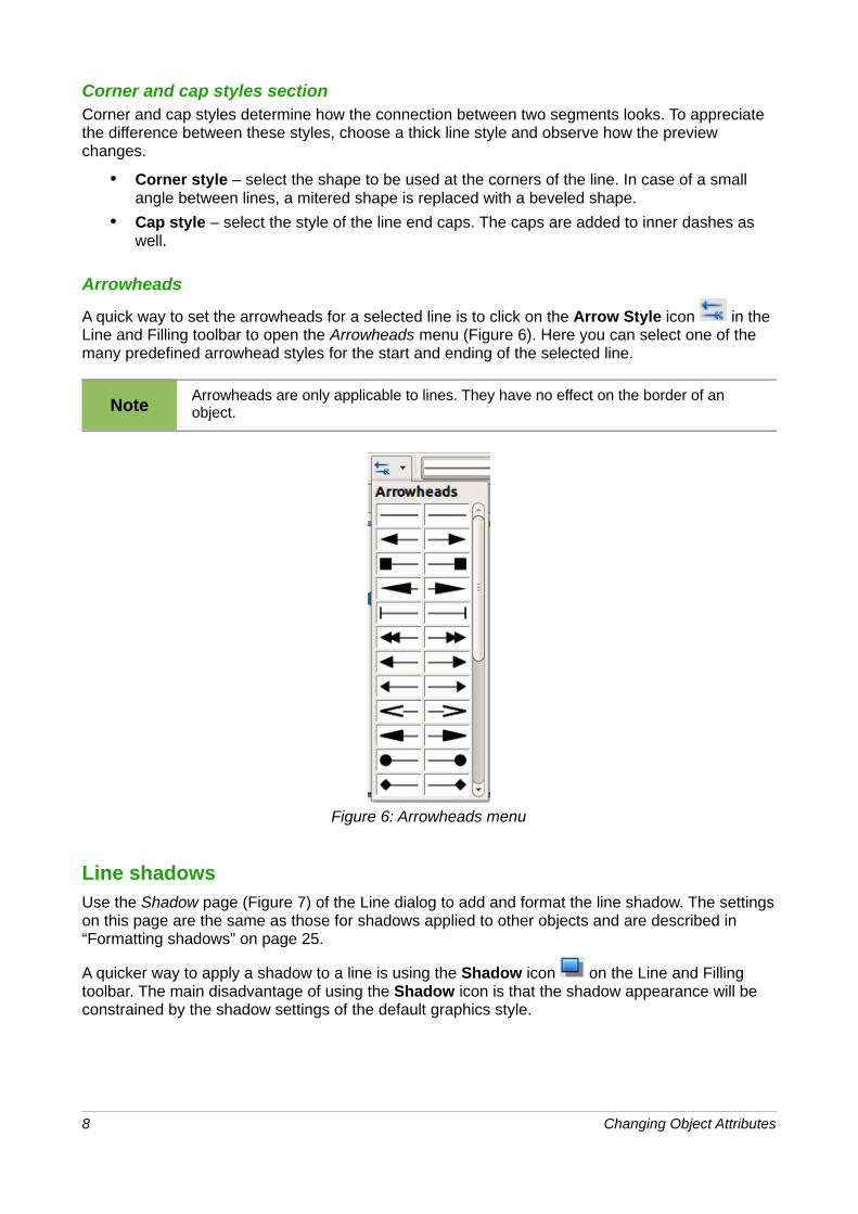
Arrowheads
A quick way to set the arrowheads for a selected line is to click on the Arrow Style icon in the Line and Filling toolbar to open the Arrowheads menu (Figure 6). Here you can select one of the many predefined arrowhead styles for the start and ending of the selected line.
NoteArrowheads are only applicable to lines. They have no effect on the border of an object.
Figure 6: Arrowheads menu
Line shadowsUse the Shadow page (Figure 7) of the Line dialog to add and format the line shadow. The settingson this page are the same as those for shadows applied to other objects and are described in “Formatting shadows” on page 25.
A quicker way to apply a shadow to a line is using the Shadow icon on the Line and Filling toolbar. The main disadvantage of using the Shadow icon is that the shadow appearance will be constrained by the shadow settings of the default graphics style.
8 Changing Object Attributes

Figure 7: Line properties dialog – Shadow page
Line stylesUse the Line Styles page (Figure 8) of the Line dialog to create new line styles as well as to load previously saved line styles. It is normally better to create new styles when necessary than modify predefined styles.
Figure 8: Line dialog – Line Styles page
Creating line stylesTo create a new line style:
1) Choose Format > Line on the main menu bar, or right-click on the line and select Line
from the context menu, or select the Line icon on the Line and Filling toolbar to open theLine dialog.
2) Click on the Line Styles tab.
3) Select from the Line style drop-down menu a style similar to the style you want to create.
4) Click Add and type a name for the new line style in the dialog that opens, then click OK.
Formatting lines 9
5) Now define the new style. Start by selecting the line type for the new style. To alternate two line types (for example, dashes and dots) within a single line, select different types in the two Type boxes.
6) Specify the Number and Length (not available for dot style) of each of the types of line selected.
7) Set the Spacing between the various elements
8) If necessary, select Fit to line width so that the new style fits the width of the selected line.
9) The new line style created is available only in the current document. If you want to use the
line style in other documents, click the Save Line Styles icon and type a unique filename in the Save as dialog that opens. Saved styles have the file extension of .sod.
10) To use previously saved line styles, click the Load Line Styles icon and select a style from the list of saved styles. Click Open to load the style into your document.
11) If necessary, click on the Modify button to change the name of the style.
12) Click OK to close the dialog and save any changes you have made.
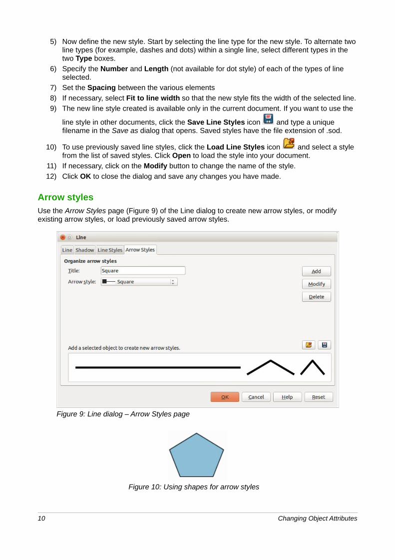
Arrow stylesUse the Arrow Styles page (Figure 9) of the Line dialog to create new arrow styles, or modify existing arrow styles, or load previously saved arrow styles.
Figure 9: Line dialog – Arrow Styles page
Figure 10: Using shapes for arrow styles
10 Changing Object Attributes
Creating arrow stylesTo create a new arrow style:
1) First draw a curve in the shape you want to use for the arrowhead, or create a shape and convert to a curve. The top of the shape must face upward, as shown in Figure 10, because this becomes the point of the arrow.
Note
The arrowhead must be a curve, which is something you can draw without lifting a pencil from the paper. For example, a star can be a curve, but a smiley face cannot be a curve because you have to reposition the pencil on the paper to draw eyes anda mouth on the face.
2) Select the shape and, if necessary, right-click and choose Convert > To Curve to convert the shape to a curve. If the shape is already a curve, To Curve will not be available.
3) With the selection handles showing, select Format > Line from the menu bar, or right-click and choose Line from the pop-up menu.
4) Go to the Arrow styles page, click the Add button, type a name for the new arrow style, andclick OK. The new arrowhead style will be shown in the preview.
5) Now you can access the new style from the Arrow style list. When you select the name of the new style, it is shown at the bottom of the dialog.
6) The new arrowhead style created is available only in the current document. If you want to
use this arrowhead style in other documents, click the Save Line Styles icon and type a unique filename in the Save as dialog that opens. Saved styles have the file extension of .sod.
7) To use previously saved arrowhead styles, click the Load Line Styles icon and select the style from the saved list of styles. Click Open to load the style into your document.
8) If necessary. click on the Modify button to change the name of the style.
9) Click OK to close the dialog and save any changes you have made.
Formatting fill area
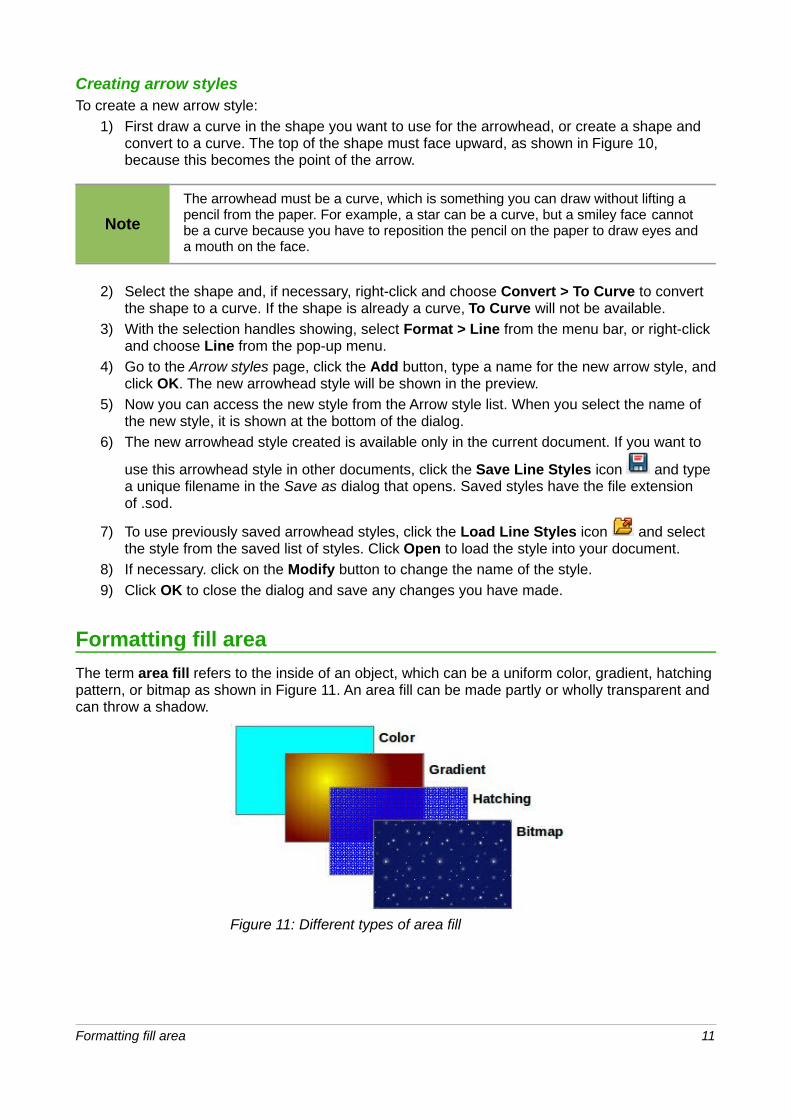
The term area fill refers to the inside of an object, which can be a uniform color, gradient, hatching pattern, or bitmap as shown in Figure 11. An area fill can be made partly or wholly transparent and can throw a shadow.
Figure 11: Different types of area fill
Formatting fill area 11

Line and Filling toolbarTools on the Line and Filling toolbar (Figure 1) provide a wide number of default fillings readily available to quickly format graphic objects. If this toolbar is not showing, go to View > Toolbars > Line and Filling on the main menu bar. To format the area of an object:
1) Select an object so that the selection handles are displayed.
2) Click on the left Area Style/Filling drop-down list and select the type of fill required (None, Color, Gradient, Hatching, or Bitmap) (Figure 12).
3) Click on the right Area Style/Filling drop-down list and select one of the available options for the selected type of area fill as shown in Figure 13, Figure 14,Figure 15 and Figure 16. For more information on area fills, see “Area dialog” on Page 13.
4) Deselect the object to save your changes to the object.
Figure 12: Area fill types
Figure 13: Color area fill Figure 14: Gradient area fill
Figure 15: Hatching area fill Figure 16: Bitmap image area fill
12 Changing Object Attributes
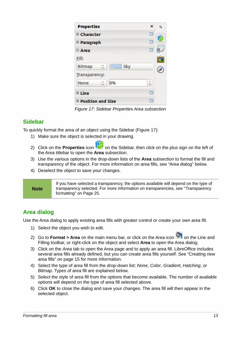
Figure 17: Sidebar Properties Area subsection
SidebarTo quickly format the area of an object using the Sidebar (Figure 17):
1) Make sure the object is selected in your drawing.
2) Click on the Properties icon on the Sidebar, then click on the plus sign on the left of the Area titlebar to open the Area subsection.
3) Use the various options in the drop-down lists of the Area subsection to format the fill and transparency of the object. For more information on area fills, see “Area dialog” below.
4) Deselect the object to save your changes.
NoteIf you have selected a transparency, the options available will depend on the type of transparency selected. For more information on transparencies, see “Transparency formatting” on Page 25.
Area dialogUse the Area dialog to apply existing area fills with greater control or create your own area fill.
1) Select the object you wish to edit.
2) Go to Format > Area on the main menu bar, or click on the Area icon on the Line and Filling toolbar, or right-click on the object and select Area to open the Area dialog.
3) Click on the Area tab to open the Area page and to apply an area fill. LibreOffice includes several area fills already defined, but you can create area fills yourself. See “Creating new area fills” on page 15 for more information.
4) Select the type of area fill from the drop-down list: None, Color, Gradient, Hatching, or Bitmap. Types of area fill are explained below.
5) Select the style of area fill from the options that become available. The number of available options will depend on the type of area fill selected above.
6) Click OK to close the dialog and save your changes. The area fill will then appear in the selected object.
Formatting fill area 13
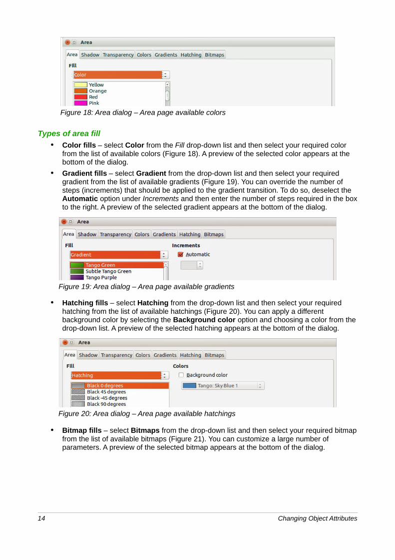
Figure 18: Area dialog – Area page available colors
Types of area fill
• Color fills – select Color from the Fill drop-down list and then select your required color from the list of available colors (Figure 18). A preview of the selected color appears at the bottom of the dialog.
• Gradient fills – select Gradient from the drop-down list and then select your required gradient from the list of available gradients (Figure 19). You can override the number of steps (increments) that should be applied to the gradient transition. To do so, deselect the Automatic option under Increments and then enter the number of steps required in the boxto the right. A preview of the selected gradient appears at the bottom of the dialog.
Figure 19: Area dialog – Area page available gradients
• Hatching fills – select Hatching from the drop-down list and then select your required hatching from the list of available hatchings (Figure 20). You can apply a different background color by selecting the Background color option and choosing a color from thedrop-down list. A preview of the selected hatching appears at the bottom of the dialog.
Figure 20: Area dialog – Area page available hatchings
• Bitmap fills – select Bitmaps from the drop-down list and then select your required bitmapfrom the list of available bitmaps (Figure 21). You can customize a large number of parameters. A preview of the selected bitmap appears at the bottom of the dialog.
14 Changing Object Attributes
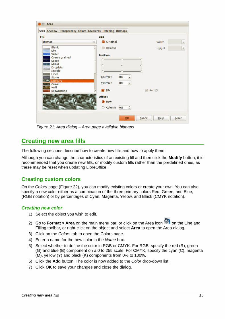
Figure 21: Area dialog – Area page available bitmaps
Creating new area fills
The following sections describe how to create new fills and how to apply them.
Although you can change the characteristics of an existing fill and then click the Modify button, it isrecommended that you create new fills, or modify custom fills rather than the predefined ones, as these may be reset when updating LibreOffice.
Creating custom colorsOn the Colors page (Figure 22), you can modify existing colors or create your own. You can also specify a new color either as a combination of the three primary colors Red, Green, and Blue, (RGB notation) or by percentages of Cyan, Magenta, Yellow, and Black (CMYK notation).
Creating new color1) Select the object you wish to edit.
2) Go to Format > Area on the main menu bar, or click on the Area icon on the Line and Filling toolbar, or right-click on the object and select Area to open the Area dialog.
3) Click on the Colors tab to open the Colors page.
4) Enter a name for the new color in the Name box.
5) Select whether to define the color in RGB or CMYK. For RGB, specify the red (R), green (G) and blue (B) component on a 0 to 255 scale. For CMYK, specify the cyan (C), magenta(M), yellow (Y) and black (K) components from 0% to 100%.
6) Click the Add button. The color is now added to the Color drop-down list.
7) Click OK to save your changes and close the dialog.
Creating new area fills 15

Figure 22: Area dialog – Colors page
Modifying colors1) Select the object you wish to edit.
2) Go to Format > Area on the main menu bar, or click on the Area icon on the Line and Filling toolbar, or right-click on the object and select Area to open the Area dialog.
3) Click on the Colors tab to open the Colors page.
4) Select the color to modify from the list.
5) Enter the new values that define the color in RGB or CMYK.
6) Modify the name as required.
7) Click Modify to save your changes.
8) Click OK to close the dialog.
Editing colors1) Select the object you wish to edit.
2) Go to Format > Area on the main menu bar, or click on the Area icon on the Line and Filling toolbar, or right-click on the object and select Area to open the Area dialog.
3) Click on the Colors tab to open the Colors page.
4) Select the color to edit from the list.
5) Click on the Edit button to open the Color Picker dialog (Figure 23).
6) Modify the color components as required using RGB, CMYK or HSB (Hue, Saturation, Brightness).
7) Click OK to exit the Color Picker dialog.
8) Modify the name as required.
9) Click Modify on the Color dialog to save your changes.
10) Click OK to close the dialog.
16 Changing Object Attributes
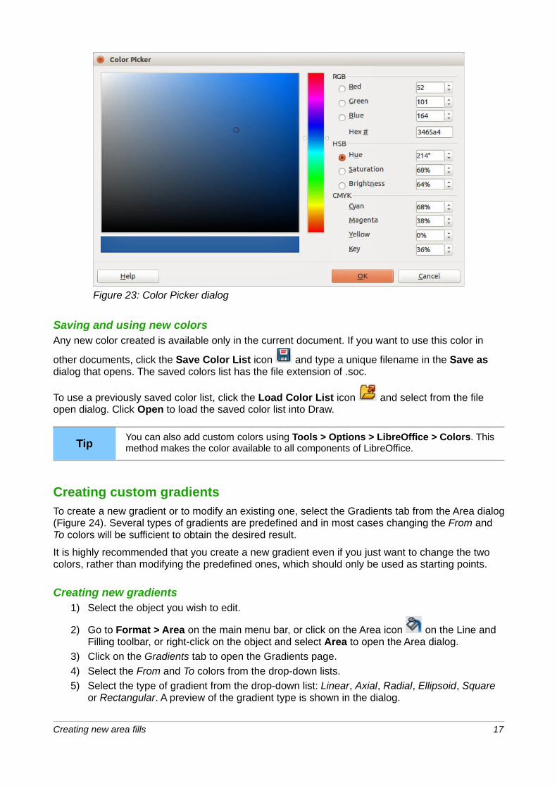
Figure 23: Color Picker dialog
Saving and using new colorsAny new color created is available only in the current document. If you want to use this color in
other documents, click the Save Color List icon and type a unique filename in the Save as dialog that opens. The saved colors list has the file extension of .soc.
To use a previously saved color list, click the Load Color List icon and select from the file open dialog. Click Open to load the saved color list into Draw.
TipYou can also add custom colors using Tools > Options > LibreOffice > Colors. Thismethod makes the color available to all components of LibreOffice.
Creating custom gradientsTo create a new gradient or to modify an existing one, select the Gradients tab from the Area dialog(Figure 24). Several types of gradients are predefined and in most cases changing the From and To colors will be sufficient to obtain the desired result.
It is highly recommended that you create a new gradient even if you just want to change the two colors, rather than modifying the predefined ones, which should only be used as starting points.
Creating new gradients1) Select the object you wish to edit.
2) Go to Format > Area on the main menu bar, or click on the Area icon on the Line and Filling toolbar, or right-click on the object and select Area to open the Area dialog.
3) Click on the Gradients tab to open the Gradients page.
4) Select the From and To colors from the drop-down lists.
5) Select the type of gradient from the drop-down list: Linear, Axial, Radial, Ellipsoid, Square or Rectangular. A preview of the gradient type is shown in the dialog.
Creating new area fills 17

Figure 24: Area Dialog – Gradients page
6) Set all the properties as desired (very often the default values will work well). The properties used to create a gradient are summarized in Table 1. Depending on the type of gradient selected, some properties may be grayed out.
7) Click Add to add the newly created gradient to the list.
8) Type a name for the new gradient in the dialog that opens and click OK.
9) Click OK to close the dialog.
Table 1: Gradient properties
Property Meaning
Center X For Radial, Ellipsoid, Square and Rectangular gradients, modify these values to set the horizontal offset of the gradient center.
Center Y For Radial, Ellipsoid, Square and Rectangular gradients, modify these values to set the vertical offset of the gradient center.
Angle For all the gradient types, specifies the angle of the gradient axis.
Border Increase this value to make the gradient start further away from the border of the shape.
From The start color for the gradient. In the edit box below enter the intensity of the color: 0% corresponds to black, 100% to the full color.
To The end color for the gradient. In the edit box below enter the intensity of the color: 0% corresponds to black, 100% to the full color.
Modifying gradients1) Select the object you wish to edit.
2) Go to Format > Area on the main menu bar, or click on the Area icon on the Line and Filling toolbar, or right-click on the object and select Area to open the Area dialog.
18 Changing Object Attributes
3) Click on the Gradients tab to open the Gradients page.
4) Select the gradient to modify from the list.
5) Enter the new values for the properties that become available for change. See Table 1 for more information on gradient properties.
6) Click Modify to save your changes.
7) Click OK to close the dialog.
Saving and using new gradientsThe new gradient created is available only in the current document. If you want to use this gradient
in other documents, click the Save Gradients List icon and type a unique filename in the Save as dialog that opens. The saved gradients list has the file extension of .sog.
To use a previously saved gradients list, click the Load Gradients List icon and select from the file open dialog. Click Open to load the saved gradients list into Draw.
Advanced gradient controlsAs discussed in “Creating custom gradients” on page 17, gradient properties can be configured using the properties given in the dialogs shown in Figure 24 and Table 1. However, LibreOffice provides advanced controls for gradients as follows.
1) Select the object you wish to edit.
2) Go to Format > Area on the main menu bar, or click on the Area icon on the Line and Filling toolbar, or right-click on the object and select Area to open the Area dialog.
3) Click on the Gradients tab to open the Gradients page (Figure 24).
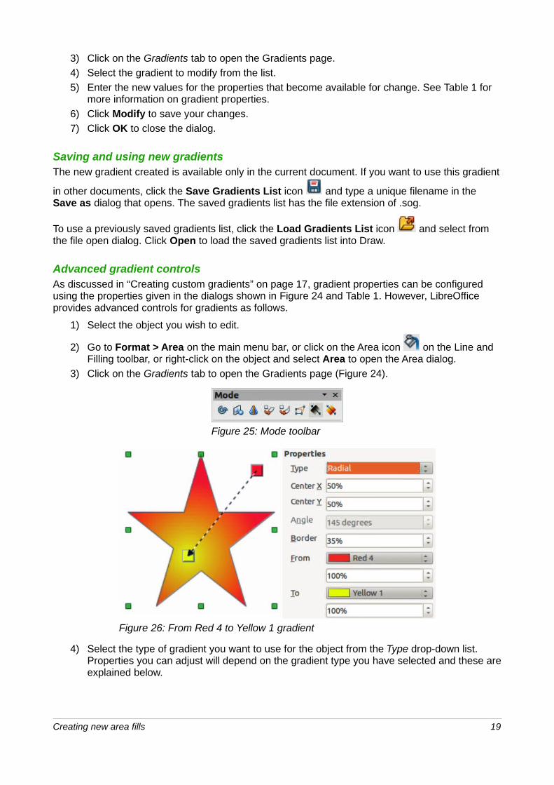
Figure 25: Mode toolbar
Figure 26: From Red 4 to Yellow 1 gradient
4) Select the type of gradient you want to use for the object from the Type drop-down list. Properties you can adjust will depend on the gradient type you have selected and these areexplained below.
Creating new area fills 19

5) Go to View > Toolbars > Mode on the main menu bar, click on the Effects icon on theLine and Filling toolbar to open the Mode toolbar.
– Click on the Gradient icon in the Mode toolbar (Figure 25). This displays a dashed line connecting two colored squares. The colors show the From and To colors that are used for the selected gradient (Figure 26).
– For linear gradients – move the square corresponding to the From color to change where the gradient starts (border value). Move the square corresponding to the To colorto change the orientation (angle value).
– For axial gradients – move the To color to change both the angle and border properties of the gradient. Only the square corresponding to the To color can be moved.
– For radial gradients – move the From color to modify the border property to set the width of the gradient circle. Move the To color to change the point where the gradient ends (Center X and Center Y values).
– For ellipsoid gradients – move the From color to modify the border property to set the size of the gradient ellipsoid. Move the To color to change the angle of the ellipsoid axisand the axis itself.
– For square and rectangular gradients – move the From color to modify the border to set the size of the gradient square or rectangle and the angle of the gradient shape. Move the To color to change the center of the gradient.
6) Click OK to save your changes and close the Area dialog.
NoteMoving the squares will have different effects depending on the type of gradient. For example, for a linear gradient, the start and end squares of the gradient will always be situated to either side of the center point of the object.
Creating custom hatching patternsTo create new hatching patterns or modify existing ones, select the Hatching tab of the Area dialog (Figure 27). As with gradients and colors, it is better to create a new hatching pattern rather than modify a predefined one. The properties that can be set for a hatching pattern are shown in Table 2.
Table 2: Hatching pattern properties
Property Meaning
Spacing Determines the spacing between two lines of the pattern. As the value is changed the preview window is updated.
Angle Use the mini map below the numerical value to quickly set the angle formed bythe line to multiples of 45 degrees. If the required angle is not a multiple of 45 degrees, just enter the desired value in the edit box.
Line type Set single, double or triple line for the style of the pattern.
Line color Use the list to select the color of the lines that will form the pattern.
20 Changing Object Attributes
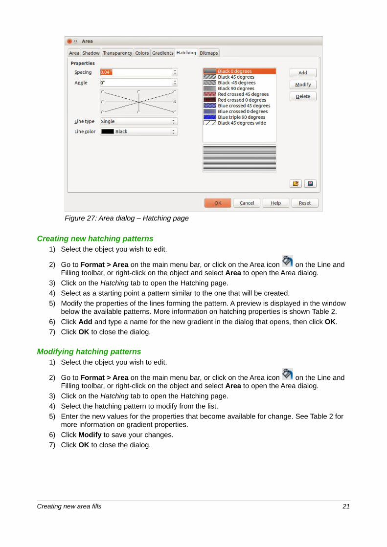
Figure 27: Area dialog – Hatching page
Creating new hatching patterns1) Select the object you wish to edit.
2) Go to Format > Area on the main menu bar, or click on the Area icon on the Line and Filling toolbar, or right-click on the object and select Area to open the Area dialog.
3) Click on the Hatching tab to open the Hatching page.
4) Select as a starting point a pattern similar to the one that will be created.
5) Modify the properties of the lines forming the pattern. A preview is displayed in the window below the available patterns. More information on hatching properties is shown Table 2.
6) Click Add and type a name for the new gradient in the dialog that opens, then click OK.
7) Click OK to close the dialog.
Modifying hatching patterns1) Select the object you wish to edit.
2) Go to Format > Area on the main menu bar, or click on the Area icon on the Line and Filling toolbar, or right-click on the object and select Area to open the Area dialog.
3) Click on the Hatching tab to open the Hatching page.
4) Select the hatching pattern to modify from the list.
5) Enter the new values for the properties that become available for change. See Table 2 for more information on gradient properties.
6) Click Modify to save your changes.
7) Click OK to close the dialog.
Creating new area fills 21

Saving and using new hatching patternsThe new hatching pattern created is available only in the current document. If you want to use this
hatching pattern in other documents, click the Save Hatches List icon and type a unique filename in the Save as dialog that opens. The saved hatches list has the file extension of .soh.
To use a previously saved hatches list, click the Load Hatches List icon and select from the file open dialog. Click Open to load the saved hatches list into Draw.
Working with bitmap fills1) Select the object you wish to edit.
2) Go to Format > Area on the main menu bar, or click on the Area icon on the Line and Filling toolbar, or right-click on the object and select Area to open the Area dialog.
3) Click on the Area tab to open the Area page.
4) Select Bitmap from the Fill drop-down list (Figure 21 on Page 15).
5) Select from the list of bitmaps the one to be used to fill the area. Note that any imported bitmaps will become available in the list.
6) Set the size, position and offset parameters (as applicable). See Table 3 for more information on bitmap properties. The best way to acquire understanding of these parameters is to use them. Figure 21 on Page 15 shows some examples of bitmap fills andthe parameters used.
7) Click OK to close the dialog.
Figure 28: Examples of bitmap fill
Table 3: Bitmap fill properties
Property Meaning
Size – Original Select this box to retain the original size of the bitmap.
Size – Relative To rescale the object, deselect Original and select Relative. The Width and Height edit boxes are enabled.
22 Changing Object Attributes
Property Meaning
Size – Width When Relative is selected 100% means that the bitmap original width will be resized to occupy the whole fill area width, 50% means that the width of the bitmap will be half that of the fill area.
Size – Height When Relative is selected 100% means that the bitmap original height will be resized to occupy the whole fill area height, 50% means that the height of the bitmap will be half that of the fill area.
Position – Anchor Map
Select from the map the place within the area to which the bitmap should be anchored.
Position – Tile When this option is selected, the bitmap will be tiled to fill the area. The size of the bitmap used for the tiling is determined by the Size settings.
Position – X offset When Tile is enabled, enter in this box the offset for the width of the bitmap in percentage values. 50% offset means that Draw will place the middle part of the bitmap at the anchor point and start tiling from there.
Position – Y offset This will have a similar effect to the X offset, but will work on the height of the bitmap.
Position – Autofit Stretches the bitmap to fill the whole area. Selecting this option disables all the size settings.
Offset – Row If Tile is enabled, offsets the rows of tiled bitmaps by the percentage entered in the box so that two subsequent rows are not aligned.
Offset – Column If Tile is enabled, offsets the columns of tiled bitmaps by the percentage entered in the box so that two subsequent columns of bitmaps are not aligned.
Creating and importing bitmapsYou can add (import) new bitmap fills or create your own pattern on an 8x8 grid using the Bitmaps tab of the Area dialog (Figure 29).
Creating bitmap fills1) Select the object you wish to edit.
2) Go to Format > Area on the main menu bar, or click on the Area icon on the Line and Filling toolbar, or right-click on the object and select Area to open the Area dialog.
3) Click on the Bitmap tab to open the Bitmap page.
4) Select Blank as the bitmap type to activate the Pattern Editor.
5) Select the Foreground and Background colors.
6) Start creating the pattern by clicking with the left mouse button the squares (pixels) that youwant in the foreground color. Use the right mouse button to apply the background color. Check the preview window to see if the desired effect is achieved.
7) Click Add to save the pattern and type a name for the new gradient in the dialog that opens, then click OK.
8) Click OK to close the dialog.
NoteYou can only modify bitmaps that you have created in LibreOffice. The bitmaps supplied with LibreOffice or imported bitmaps cannot be changed or modified using LibreOffice.
Creating new area fills 23
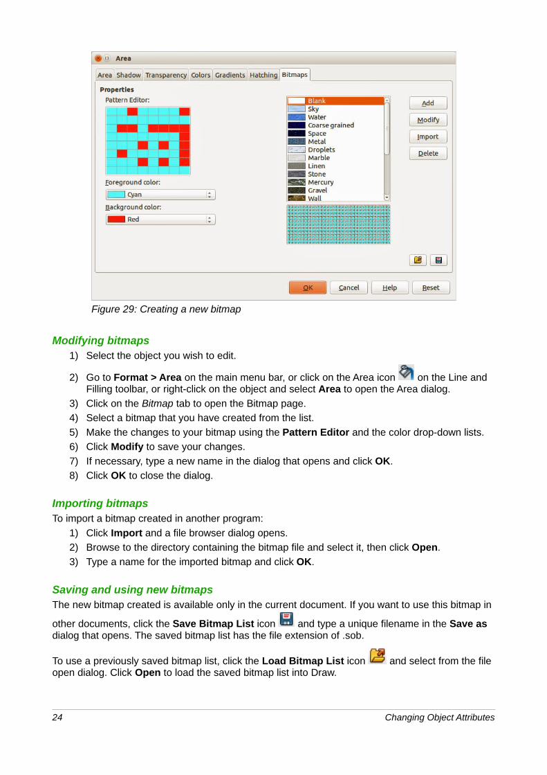
Figure 29: Creating a new bitmap
Modifying bitmaps1) Select the object you wish to edit.
2) Go to Format > Area on the main menu bar, or click on the Area icon on the Line and Filling toolbar, or right-click on the object and select Area to open the Area dialog.
3) Click on the Bitmap tab to open the Bitmap page.
4) Select a bitmap that you have created from the list.
5) Make the changes to your bitmap using the Pattern Editor and the color drop-down lists.
6) Click Modify to save your changes.
7) If necessary, type a new name in the dialog that opens and click OK.
8) Click OK to close the dialog.
Importing bitmapsTo import a bitmap created in another program:
1) Click Import and a file browser dialog opens.
2) Browse to the directory containing the bitmap file and select it, then click Open.
3) Type a name for the imported bitmap and click OK.
Saving and using new bitmapsThe new bitmap created is available only in the current document. If you want to use this bitmap in
other documents, click the Save Bitmap List icon and type a unique filename in the Save as dialog that opens. The saved bitmap list has the file extension of .sob.
To use a previously saved bitmap list, click the Load Bitmap List icon and select from the file open dialog. Click Open to load the saved bitmap list into Draw.
24 Changing Object Attributes
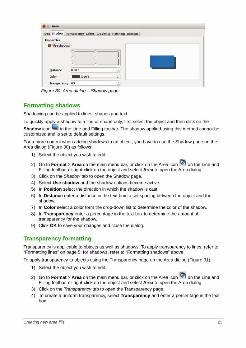
Figure 30: Area dialog – Shadow page
Formatting shadowsShadowing can be applied to lines, shapes and text.
To quickly apply a shadow to a line or shape only, first select the object and then click on the
Shadow icon in the Line and Filling toolbar. The shadow applied using this method cannot be customized and is set to default settings.
For a more control when adding shadows to an object, you have to use the Shadow page on the Area dialog (Figure 30) as follows:
1) Select the object you wish to edit.
2) Go to Format > Area on the main menu bar, or click on the Area icon on the Line and Filling toolbar, or right-click on the object and select Area to open the Area dialog.
3) Click on the Shadow tab to open the Shadow page.
4) Select Use shadow and the shadow options become active.
5) In Position select the direction in which the shadow is cast.
6) In Distance enter a distance in the text box to set spacing between the object and the shadow.
7) In Color select a color form the drop-down list to determine the color of the shadow.
8) In Transparency enter a percentage in the text box to determine the amount of transparency for the shadow.
9) Click OK to save your changes and close the dialog.
Transparency formattingTransparency is applicable to objects as well as shadows. To apply transparency to lines, refer to “Formatting lines” on page 5; for shadows, refer to “Formatting shadows” above.
To apply transparency to objects using the Transparency page on the Area dialog (Figure 31):
1) Select the object you wish to edit.
2) Go to Format > Area on the main menu bar, or click on the Area icon on the Line and Filling toolbar, or right-click on the object and select Area to open the Area dialog.
3) Click on the Transparency tab to open the Transparency page.
4) To create a uniform transparency, select Transparency and enter a percentage in the text box.
Creating new area fills 25
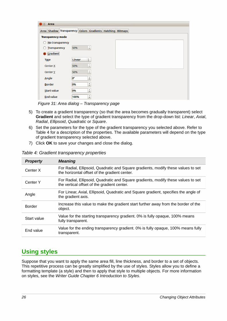
Figure 31: Area dialog – Transparency page
5) To create a gradient transparency (so that the area becomes gradually transparent) select Gradient and select the type of gradient transparency from the drop-down list: Linear, Axial,Radial, Ellipsoid, Quadratic or Square.
6) Set the parameters for the type of the gradient transparency you selected above. Refer toTable 4 for a description of the properties. The available parameters will depend on the typeof gradient transparency selected above.
7) Click OK to save your changes and close the dialog.
Table 4: Gradient transparency properties
Property Meaning
Center XFor Radial, Ellipsoid, Quadratic and Square gradients, modify these values to set the horizontal offset of the gradient center.
Center YFor Radial, Ellipsoid, Quadratic and Square gradients, modify these values to set the vertical offset of the gradient center.
AngleFor Linear, Axial, Ellipsoid, Quadratic and Square gradient, specifies the angle of the gradient axis.
BorderIncrease this value to make the gradient start further away from the border of the object.
Start valueValue for the starting transparency gradient. 0% is fully opaque, 100% means fully transparent.
End valueValue for the ending transparency gradient. 0% is fully opaque, 100% means fullytransparent.
Using styles
Suppose that you want to apply the same area fill, line thickness, and border to a set of objects. This repetitive process can be greatly simplified by the use of styles. Styles allow you to define a formatting template (a style) and then to apply that style to multiple objects. For more information on styles, see the Writer Guide Chapter 6 Introduction to Styles.
26 Changing Object Attributes
Linked drawing object stylesDrawing object styles support inheritance; that is, a style can be linked to another (parent) style so that it inherits all the formatting settings of the parent. You can use this property to create families of styles.
For example, if you need multiple boxes that differ in color but are otherwise identically formatted, the best way to proceed is to define a generic style for the box including borders, area fill, font, andso on. Then create a number of hierarchically dependent styles which differ only in the fill color attribute. If you then need to change the font size or the thickness of the border, it is sufficient to change the parent style and all the other linked styles will change accordingly.
Creating drawing object stylesYou can create a new drawing object style in the following ways:
• Using the Styles and Formatting dialog.
• Using the Styles and Formatting section on the Sidebar.
• From a selected object.
NoteIn LibreOffice Draw, only Drawing Object Styles are available in the Styles and Formatting dialog and the Styles and Formatting section on the Sidebar.
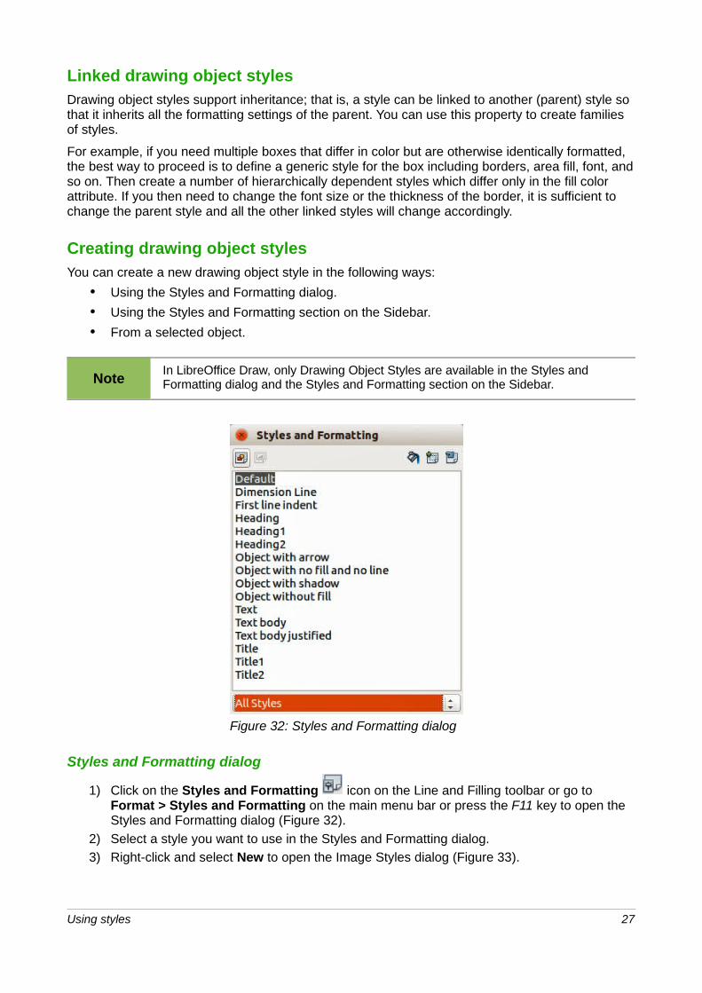
Figure 32: Styles and Formatting dialog
Styles and Formatting dialog
1) Click on the Styles and Formatting icon on the Line and Filling toolbar or go to Format > Styles and Formatting on the main menu bar or press the F11 key to open the Styles and Formatting dialog (Figure 32).
2) Select a style you want to use in the Styles and Formatting dialog.
3) Right-click and select New to open the Image Styles dialog (Figure 33).
Using styles 27
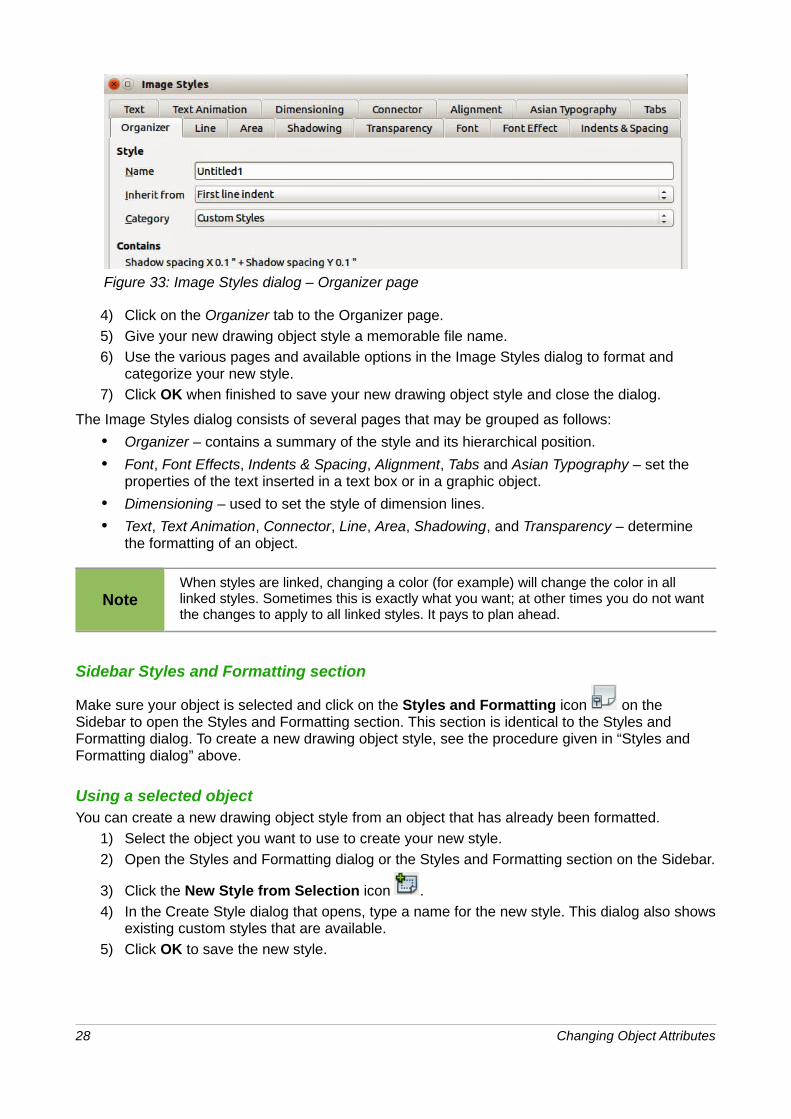
Figure 33: Image Styles dialog – Organizer page
4) Click on the Organizer tab to the Organizer page.
5) Give your new drawing object style a memorable file name.
6) Use the various pages and available options in the Image Styles dialog to format and categorize your new style.
7) Click OK when finished to save your new drawing object style and close the dialog.
The Image Styles dialog consists of several pages that may be grouped as follows:
• Organizer – contains a summary of the style and its hierarchical position.
• Font, Font Effects, Indents & Spacing, Alignment, Tabs and Asian Typography – set the properties of the text inserted in a text box or in a graphic object.
• Dimensioning – used to set the style of dimension lines.
• Text, Text Animation, Connector, Line, Area, Shadowing, and Transparency – determine the formatting of an object.
NoteWhen styles are linked, changing a color (for example) will change the color in all linked styles. Sometimes this is exactly what you want; at other times you do not want the changes to apply to all linked styles. It pays to plan ahead.
Sidebar Styles and Formatting section
Make sure your object is selected and click on the Styles and Formatting icon on the Sidebar to open the Styles and Formatting section. This section is identical to the Styles and Formatting dialog. To create a new drawing object style, see the procedure given in “Styles and Formatting dialog” above.
Using a selected objectYou can create a new drawing object style from an object that has already been formatted.
1) Select the object you want to use to create your new style.
2) Open the Styles and Formatting dialog or the Styles and Formatting section on the Sidebar.
3) Click the New Style from Selection icon .
4) In the Create Style dialog that opens, type a name for the new style. This dialog also showsexisting custom styles that are available.
5) Click OK to save the new style.
28 Changing Object Attributes
Modifying drawing object stylesTo modify an existing style:
1) Right-click on the style in the Styles and Formatting dialog or the Styles and Formatting section on the Sidebar.
2) Select Modify from the context menu to open the Image styles dialog (Figure 33).
3) Make the required changes to the style.
4) Click OK to save your changes and close the dialog.
Updating from a selectionTo update a drawing object style from a selected object:
1) Select an object that uses the format you want to adopt as a style.
2) In the Styles and Formatting dialog or the Styles and Formatting section on the Sidebar,
select the style you want to update and then click the Update Style icon .
Applying drawing object stylesYou can apply a drawing object style using the Styles and Formatting dialog or the Styles and Formatting section on the Sidebar. First make sure that the styles are shown (Figure 32), then do one of the following:
• Select the object to which you want to apply a style and double-click on the name of the style you want to apply.
• Click the Fill Format mode icon , position the cursor on the object to be styled and click the mouse button. This mode remains active until you turn it off, so you can apply the same style to several objects. To quit Fill Format mode, click the Fill Format mode icon again or press the Esc key.
• When Fill Format mode is active, a right-click anywhere in the document cancels the last Fill Format action. Be careful not to accidentally right-click and thus undo actions you want to keep.
TipAt the bottom of the Styles and Formatting dialog or the Styles and Formatting section on the Sidebar there is a drop-down list. Here you can choose to show all styles or groups of styles such as applied styles or custom styles.
Deleting drawing object stylesYou cannot delete any of the predefined styles in LibreOffice, even if you are not using them. You can only delete user-defined (custom) styles. However, before you delete a custom style, make sure the style is not in use. If an unwanted style is in use, make sure you replace it with another style. To see which style are in use, choose Applied Styles in the drop-down list at the bottom of the Styles and Formatting dialog.
To delete a custom style, right-click on the style in the Styles and Formatting dialog and choose Delete on the context menu. If the style is in use, a warning message will appear; you can click Yes to delete the style anyway. If the style is not in use, no confirmation message appears.
Using styles 29
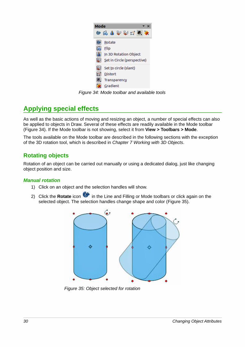
Figure 34: Mode toolbar and available tools
Applying special effects
As well as the basic actions of moving and resizing an object, a number of special effects can also be applied to objects in Draw. Several of these effects are readily available in the Mode toolbar (Figure 34). If the Mode toolbar is not showing, select it from View > Toolbars > Mode.
The tools available on the Mode toolbar are described in the following sections with the exception of the 3D rotation tool, which is described in Chapter 7 Working with 3D Objects.
Rotating objectsRotation of an object can be carried out manually or using a dedicated dialog, just like changing object position and size.
Manual rotation1) Click on an object and the selection handles will show.
2) Click the Rotate icon in the Line and Filling or Mode toolbars or click again on the selected object. The selection handles change shape and color (Figure 35).
Figure 35: Object selected for rotation
30 Changing Object Attributes
3) If necessary, click and drag the pivot point for rotation to change the way an object is rotated. The pivot point is a circle and appears, by default, in the middle of the selected object. Normally the center of an object will be just fine, but on some occasions you may wish to rotate around a corner or even around a point outside the object.
4) Move the mouse over one of the corner handles and the cursor changes shape.
5) Click the mouse and move in the direction in which you want to rotate the object. Only the corner selection handles are active for rotation.
6) To restrict the rotation angles to multiples of 15 degrees, press and hold the Shift key while rotating the object. This is very handy for rotating objects through a right angle, for examplefrom portrait to landscape.
7) When satisfied release the mouse button.
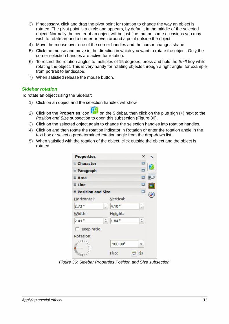
Sidebar rotationTo rotate an object using the Sidebar:
1) Click on an object and the selection handles will show.
2) Click on the Properties icon on the Sidebar, then click on the plus sign (+) next to the Position and Size subsection to open this subsection (Figure 36).
3) Click on the selected object again to change the selection handles into rotation handles.
4) Click on and then rotate the rotation indicator in Rotation or enter the rotation angle in the text box or select a predetermined rotation angle from the drop-down list.
5) When satisfied with the rotation of the object, click outside the object and the object is rotated.
Figure 36: Sidebar Properties Position and Size subsection
Applying special effects 31
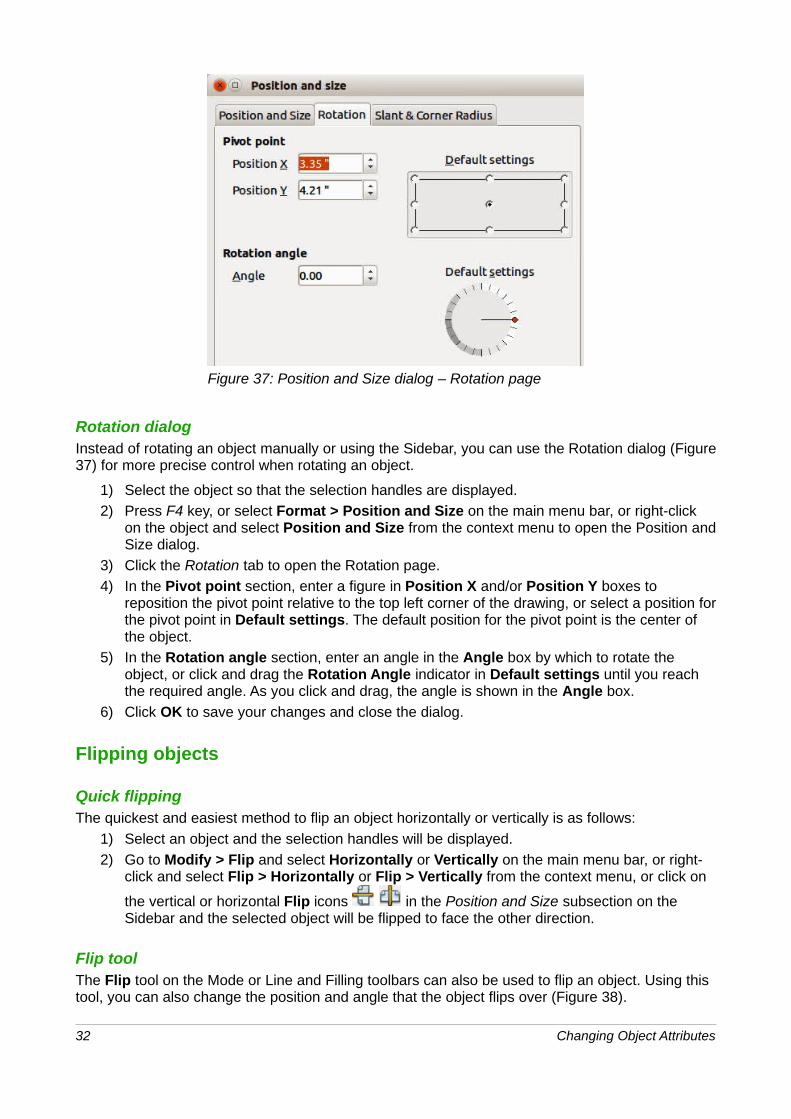
Figure 37: Position and Size dialog – Rotation page
Rotation dialogInstead of rotating an object manually or using the Sidebar, you can use the Rotation dialog (Figure37) for more precise control when rotating an object.
1) Select the object so that the selection handles are displayed.
2) Press F4 key, or select Format > Position and Size on the main menu bar, or right-click on the object and select Position and Size from the context menu to open the Position andSize dialog.
3) Click the Rotation tab to open the Rotation page.
4) In the Pivot point section, enter a figure in Position X and/or Position Y boxes to reposition the pivot point relative to the top left corner of the drawing, or select a position forthe pivot point in Default settings. The default position for the pivot point is the center of the object.
5) In the Rotation angle section, enter an angle in the Angle box by which to rotate the object, or click and drag the Rotation Angle indicator in Default settings until you reach the required angle. As you click and drag, the angle is shown in the Angle box.
6) Click OK to save your changes and close the dialog.
Flipping objects
Quick flippingThe quickest and easiest method to flip an object horizontally or vertically is as follows:
1) Select an object and the selection handles will be displayed.
2) Go to Modify > Flip and select Horizontally or Vertically on the main menu bar, or right-click and select Flip > Horizontally or Flip > Vertically from the context menu, or click on
the vertical or horizontal Flip icons in the Position and Size subsection on the Sidebar and the selected object will be flipped to face the other direction.
Flip toolThe Flip tool on the Mode or Line and Filling toolbars can also be used to flip an object. Using this tool, you can also change the position and angle that the object flips over (Figure 38).
32 Changing Object Attributes
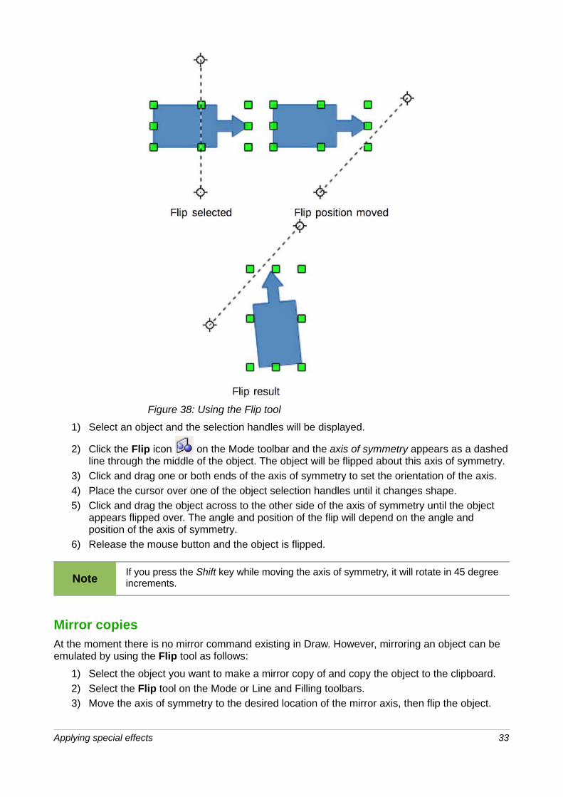
Figure 38: Using the Flip tool
1) Select an object and the selection handles will be displayed.
2) Click the Flip icon on the Mode toolbar and the axis of symmetry appears as a dashedline through the middle of the object. The object will be flipped about this axis of symmetry.
3) Click and drag one or both ends of the axis of symmetry to set the orientation of the axis.
4) Place the cursor over one of the object selection handles until it changes shape.
5) Click and drag the object across to the other side of the axis of symmetry until the object appears flipped over. The angle and position of the flip will depend on the angle and position of the axis of symmetry.
6) Release the mouse button and the object is flipped.
NoteIf you press the Shift key while moving the axis of symmetry, it will rotate in 45 degreeincrements.
Mirror copiesAt the moment there is no mirror command existing in Draw. However, mirroring an object can be emulated by using the Flip tool as follows:
1) Select the object you want to make a mirror copy of and copy the object to the clipboard.
2) Select the Flip tool on the Mode or Line and Filling toolbars.
3) Move the axis of symmetry to the desired location of the mirror axis, then flip the object.
Applying special effects 33
4) Click on an empty area of the page to deselect the object.
5) Paste from the clipboard to put a copy of the object back into its original location and now you have a mirror copy.
6) If necessary, select both objects and realign them by going to Modify>Alignment on the main menu bar, or right-click and select Alignment from the context menu and then select the type of alignment.
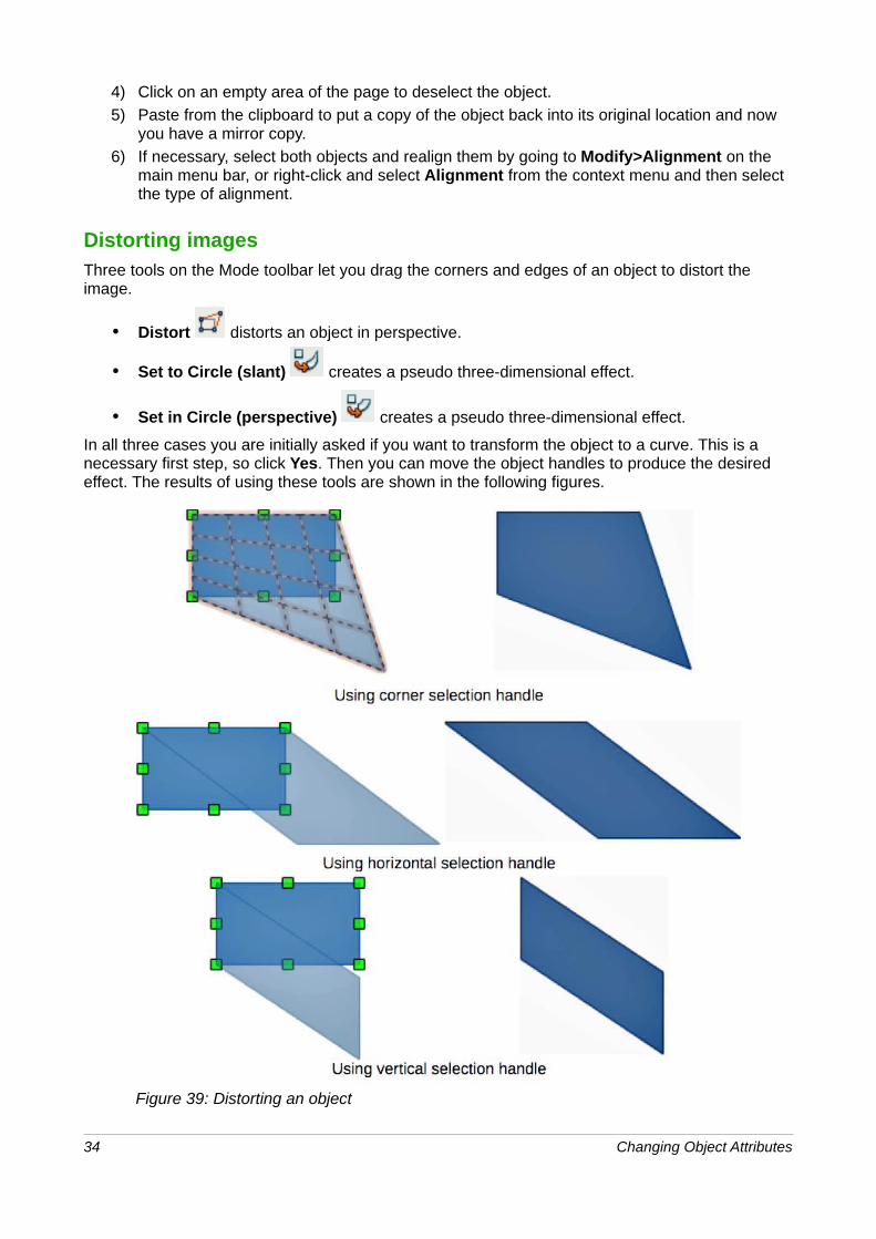
Distorting imagesThree tools on the Mode toolbar let you drag the corners and edges of an object to distort the image.
• Distort distorts an object in perspective.
• Set to Circle (slant) creates a pseudo three-dimensional effect.
• Set in Circle (perspective) creates a pseudo three-dimensional effect.
In all three cases you are initially asked if you want to transform the object to a curve. This is a necessary first step, so click Yes. Then you can move the object handles to produce the desired effect. The results of using these tools are shown in the following figures.
Figure 39: Distorting an object
34 Changing Object Attributes
Distorting
Select an object and click on the Distort icon on the Mode toolbar. After converting to a curve as requested, move the handles to stretch the object. The corner handles distort the corners, the vertical midpoint handles distort the figure horizontally and the horizontal ones distort it vertically (Figure 39).
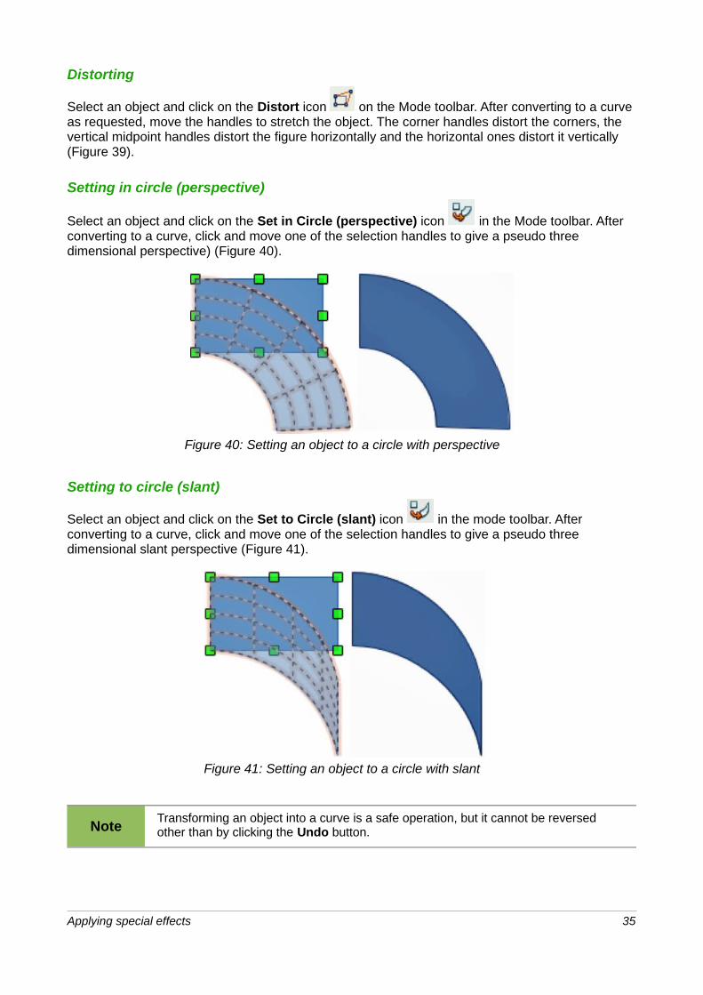
Setting in circle (perspective)
Select an object and click on the Set in Circle (perspective) icon in the Mode toolbar. After converting to a curve, click and move one of the selection handles to give a pseudo three dimensional perspective) (Figure 40).
Figure 40: Setting an object to a circle with perspective
Setting to circle (slant)
Select an object and click on the Set to Circle (slant) icon in the mode toolbar. After converting to a curve, click and move one of the selection handles to give a pseudo three dimensional slant perspective (Figure 41).
Figure 41: Setting an object to a circle with slant
NoteTransforming an object into a curve is a safe operation, but it cannot be reversed other than by clicking the Undo button.
Applying special effects 35

Dynamic gradientsYou can control transparency gradients in the same manner as color gradients and both types of gradient can be used together. With a transparency gradient, the direction and degree of object fill color changes from opaque to transparent. In a color gradient, the fill changes from one color to another, but the degree of transparency remains the same.
Two icons are present on the Mode toolbar to dynamically control transparency and color gradients. Even if you have not assigned transparency to an object with a color fill, you can control
the transparency by clicking on the Transparency icon . This defines a transparency gradient and a dashed line connecting two squares appears on the object. Move the two squares to modify the gradient. You can define the direction of the gradient (vertical, horizontal, or at any angle) and the spot at which the transparency begins.
A regular color gradient is defined in the same manner. Select an object, then select a gradient fill
from the Gradients page of the Area dialog (Figure 24 on page 18). The Gradient icon is nowactive on the Mode toolbar. When you click on the gradient icon, a dashed line connecting two squares appears on the object, just as it does for a transparency gradient.
In both transparency gradient and gradient fill, click outside the object to set the gradient.
NoteMoving the squares will have different effects, depending on the type of gradient. For example, for a linear gradient, the start and end squares of the gradient will always be situated to either side of the center point of the object.
Example 1A single color object and a transparency gradient, covering part of the underlying object. The gradient can be dynamically adjusted; the direction of transparency by moving the white square or the distance over which it is applied by moving the black square (Figure 42).
Figure 42: Example 1 of a dynamic gradient
Example 2An object with a color gradient, completely covering another object. The gradient is adjusted dynamically by moving the squares – the color of the square relating to the increase or decrease inthat color (Figure 43).
36 Changing Object Attributes
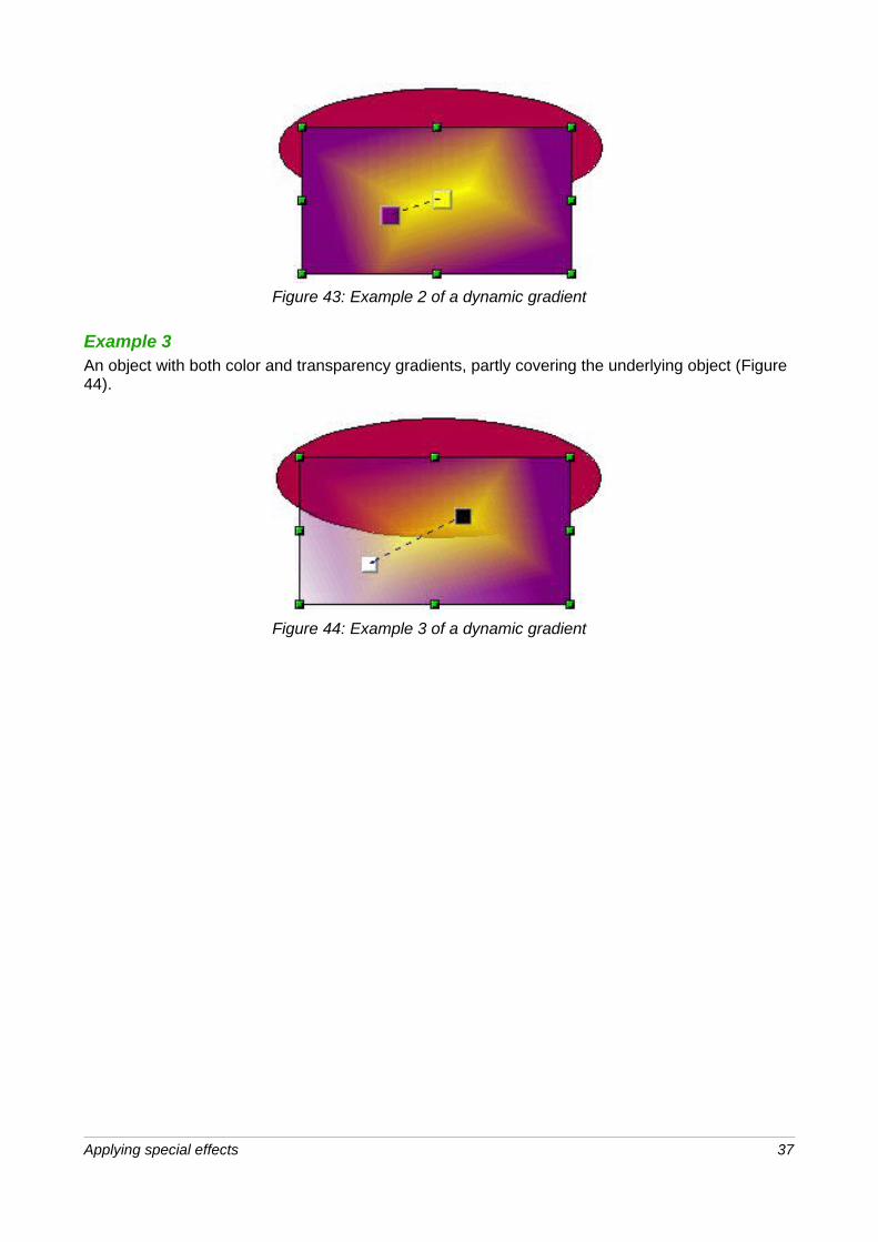
Figure 43: Example 2 of a dynamic gradient
Example 3An object with both color and transparency gradients, partly covering the underlying object (Figure 44).
Figure 44: Example 3 of a dynamic gradient
Applying special effects 37