Embed Size (px)
Citation preview

. . . . . .
Multi-Layer Resilience Optimization Model Solution of the Optimization Model Numerical Results Conclusion
Challenging Column Generation Models forthe Design of Survivable IP-over-WDM
Networks
Brigitte Jaumard⋆
A. Hoang and M. Buy
Concordia UniversityComputer Science and Software Engineering Department
⋆ CURC Chair (Tier I) - Optimization of Communication Networks
June 11, 2012
1 / 36

. . . . . .
Multi-Layer Resilience Optimization Model Solution of the Optimization Model Numerical Results Conclusion
Cross layer optimization (1/5)
2 / 36

. . . . . .
Multi-Layer Resilience Optimization Model Solution of the Optimization Model Numerical Results Conclusion
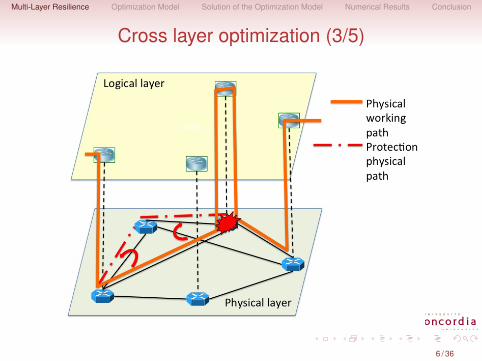
IP Restoration vs. Optical Protection?Multi-layer restoration is a critical point in current opticalsurvivability research.Logical layer and optical (physical) layer must be resilientto network failures (physical link or node failures)Backup mechanisms: restoration in the logical layer,protection in the optical layerJoint IP/optical restoration mechanism is the trend in nextgeneration optical network
Reduce the energy consumption:Energy bottleneck in IProuters is loomingGuarantee the Service Level Agreements (SLA) withbandwidth greedy applications (video services, IPTV...)
3 / 36

. . . . . .
Multi-Layer Resilience Optimization Model Solution of the Optimization Model Numerical Results Conclusion
Optical Protection
4 / 36

. . . . . .
Multi-Layer Resilience Optimization Model Solution of the Optimization Model Numerical Results Conclusion
Cross layer optimization (2/5)
5 / 36
. . . . . .
Multi-Layer Resilience Optimization Model Solution of the Optimization Model Numerical Results Conclusion
Cross layer optimization (3/5)
6 / 36

. . . . . .
Multi-Layer Resilience Optimization Model Solution of the Optimization Model Numerical Results Conclusion
Cross layer optimization (4/5)
7 / 36

. . . . . .
Multi-Layer Resilience Optimization Model Solution of the Optimization Model Numerical Results Conclusion
IP Restoration
8 / 36
. . . . . .
Multi-Layer Resilience Optimization Model Solution of the Optimization Model Numerical Results Conclusion
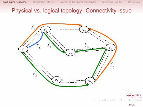
Physical vs. logical topology: Connectivity Issue
9 / 36

. . . . . .
Multi-Layer Resilience Optimization Model Solution of the Optimization Model Numerical Results Conclusion
Physical topology and Logical topology: Dual FailureA survivable topology
10 / 36

. . . . . .
Multi-Layer Resilience Optimization Model Solution of the Optimization Model Numerical Results Conclusion
Physical vs. logical topology: Dual FailureA non survivable topology
11 / 36

. . . . . .
Multi-Layer Resilience Optimization Model Solution of the Optimization Model Numerical Results Conclusion
Capacity concerns: Feasible logical← physicalmapping
12 / 36

. . . . . .
Multi-Layer Resilience Optimization Model Solution of the Optimization Model Numerical Results Conclusion
Capacity concerns: Feasible logical← physicalmapping
13 / 36

. . . . . .
Multi-Layer Resilience Optimization Model Solution of the Optimization Model Numerical Results Conclusion
Capacity concerns: Feasible IP restoration
14 / 36

. . . . . .
Multi-Layer Resilience Optimization Model Solution of the Optimization Model Numerical Results Conclusion
Logical Survivable Topology Design ProblemFor a given backbone network:
Physical Topology GP = (Vp,Ep)
Logical Topoploy GL = (VL,EL)
A set of single/multiple link (node) failures FF {{ℓ1}; {ℓ2}; {ℓ3}; {ℓ1, ℓ3}}
Finding a routing (mapping) of each logical link on the physicaltopology such that:
Minimize the mapping costIn order that the logical topology is survivable
15 / 36
. . . . . .
Multi-Layer Resilience Optimization Model Solution of the Optimization Model Numerical Results Conclusion
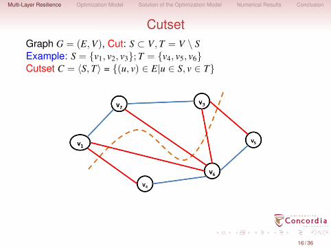
CutsetGraph G = (E,V), Cut: S ⊂ V,T = V \ SExample: S = {v1, v2, v3};T = {v4, v5, v6}Cutset C = ⟨S,T⟩ = {(u, v) ∈ E|u ∈ S, v ∈ T}
16 / 36

. . . . . .
Multi-Layer Resilience Optimization Model Solution of the Optimization Model Numerical Results Conclusion
Cutset (Cont’d)A logical topology is survivable if for any cutset, thenumber of failed logical links going through the cutset issmaller than the cardinality of that cutset.
That is, there is always at least one survivable logical linkconnecting two subsets S and T, for any subset S ⊂ V
Each cutset corresponds to a constraint.Exponential number of cutset constraints.Difficult to solve even for small network instances.
17 / 36

. . . . . .
Multi-Layer Resilience Optimization Model Solution of the Optimization Model Numerical Results Conclusion
Literature reviewMost references 7−→ ILP (Integer Linear Program) model,only scalable on particular topologies. Use heuristics todeal with meaningful sizes data instances.Modiano and Narula-Tam (2001) : particular topologies(e.g., rings) + relaxation for mesh topologies.Todimala and Ramamurthy (2007): ILP model, onlyscalable on particular topologies. Reason: an exponentialnumber of cutsets in the graph underlying the logicaltopology.Kurant and Thiran (2007) : heuristic, mapping from alogical topology to a simplified one which preserves thesurvivability.
18 / 36

. . . . . .
Multi-Layer Resilience Optimization Model Solution of the Optimization Model Numerical Results Conclusion
Literature review (Cont’d)Liu and Ruan (2007): a more flexible context - several logicallinks can be added if no survivable logical topology exists. Stilllacks scalability due to the exponential # of cutset constraints.
Kan et al. (2009) : jointly the capacity assignment and logicalsurvivability, derived some cutset constraints to guarantee thesurvivability of a logical topology.
Lin et al. (2011) : weakly vs. strongly survivable routing wherestrongly is related to limitations imposed on the routings byphysical capacity limits.
Most proposed ILP models based on the cutset theorem: a hugenumber of cutset constraints.
Usable only with data instance of (very) small size.A great effort made to reduce the number of generatedcutset constraints by exploiting some special graphstructures.Little effort put to deal efficiently with the general case.
19 / 36

. . . . . .
Multi-Layer Resilience Optimization Model Solution of the Optimization Model Numerical Results Conclusion
GeneralitiesLightpath: a connection from source to destination over thesame wavelength.A configuration is a list of mappings of logical links ↪→physical paths, on a single wavelength:
Each logical link is associated with a lightpathAll lightpaths belonging to the same configuration: samewavelength
A solution is a collection of configurations, one perwavelength such that:
Requests are satisfiedLogical topology is survivable
20 / 36

. . . . . .
Multi-Layer Resilience Optimization Model Solution of the Optimization Model Numerical Results Conclusion
Configuration Examples
21 / 36

. . . . . .
Multi-Layer Resilience Optimization Model Solution of the Optimization Model Numerical Results Conclusion
ConfigurationsA configuration c:
f cℓℓ′ = 1 if virtual link ℓ′ is routed over physical link ℓ in
configuration c, 0 otherwise.
Provides information on how many logical links cannot beprotected using additional variables and penalty coefficients:
PENALNP = 104
acℓ′ = 1 if there exists one lightpath to route logical link ℓ′, 0
otherwise, easily deduced from f cℓℓ′ .
22 / 36

. . . . . .
Multi-Layer Resilience Optimization Model Solution of the Optimization Model Numerical Results Conclusion
Cutset Optimization ModelDecision variables:
(zc)c∈C: zc = 1 if configuration c is selected, 0 otherwise.(xF
ℓ′)F∈F ,ℓ′∈EL : xFℓ′ = 1 if logical link ℓ′ is routed but cannot be
protected in case links of failure set F fail, 0 otherwise.
Objective:
min∑c∈C
∑(ℓ,ℓ′)∈EP×EL
f cℓℓ′ zc +
∑(ℓ′,F)∈EL×F
xFℓ′PENALNP. (1)
23 / 36

. . . . . .
Multi-Layer Resilience Optimization Model Solution of the Optimization Model Numerical Results Conclusion
Cutset Optimization Model (Cont’d)Constraints:
∑c∈C
acℓ′ zc ≥ 1 ℓ′ ∈ EL (2)∑
c∈C
∑ℓ∈F
∑ℓ′′∈CS(S,VL\S)
f cℓℓ′′ zc ≤ |⟨S,VL \ S⟩| − 1 + xF
ℓ′
S ⊂ VL, F ∈ F , ℓ′ ∈ EL (3)zc ∈ {0, 1} c ∈ C. (4)
24 / 36

. . . . . .
Multi-Layer Resilience Optimization Model Solution of the Optimization Model Numerical Results Conclusion
Transform Cutset Constraints into Lazy Constraints
25 / 36
. . . . . .
Multi-Layer Resilience Optimization Model Solution of the Optimization Model Numerical Results Conclusion
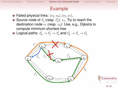
ExampleFailed physical links: (v2, v4), (v2, v7).Source node of ℓ′2 (resp. ℓ′1): v2. Try to reach thedestination node v7 (resp. v4): Use, e.g., Dijkstra tocompute minimum shortest treeLogical paths: ℓ′6 → ℓ′3 → ℓ′4 and ℓ′6 → ℓ′3 → ℓ′5
26 / 36

. . . . . .
Multi-Layer Resilience Optimization Model Solution of the Optimization Model Numerical Results Conclusion
ExampleFailed physical links: (v2, v4), (v2, v7).Source node of ℓ′2 (resp. ℓ′1): v2. Try to reach thedestination node v7 (resp. v4): Use, e.g., Dijkstra tocompute minimum shortest treeDeduce a cutset to be added to the set of constraints
27 / 36
. . . . . .
Multi-Layer Resilience Optimization Model Solution of the Optimization Model Numerical Results Conclusion
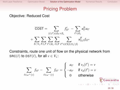
Pricing ProblemObjective: Reduced Cost
COST =∑
(ℓ,ℓ′)∈EP×EL
f cℓℓ′ −
∑ℓ′∈EL
uDℓ′aℓ′
+∑S⊂VL
∑F∈F
∑ℓ′∈EL
∑ℓ∈F
∑ℓ′′∈CS(S,VL\S)
uFS,ℓ′ fℓℓ′′
Constraints, route one unit of flow on the physical network fromSRC(ℓ) to DST(ℓ), for all v ∈ VL:
∑ℓ∈ω+(v)
fℓℓ′ −∑
ℓ∈ω−(v)
fℓℓ′ =
aℓ′ if vs(ℓ
′) = v−aℓ′ if vd(ℓ
′) = v0 otherwise
28 / 36

. . . . . .
Multi-Layer Resilience Optimization Model Solution of the Optimization Model Numerical Results Conclusion
Data setsFour different physical topologies:
Topologies # nodes# spans = Average nodal(# links)/2 degree
NJLATA 11 23 4.2NSF 14 21 3.0
EURO 19 37 3.924-NET 24 43 3.4
29 / 36

. . . . . .
Multi-Layer Resilience Optimization Model Solution of the Optimization Model Numerical Results Conclusion
Data sets
30 / 36

. . . . . .
Multi-Layer Resilience Optimization Model Solution of the Optimization Model Numerical Results Conclusion
Existence of a survivable logical topology
Instances Topo#survivable # unprotectedtopologies log. links
Cutset Todimala Cutsetet al. (2007)
NJLATAdegree 3 100 020-edge 100 0
NSF21-edge 99 76 125-edge 100 100 0
EUROdegree-3 99 87 230-edge 98 83 435-edge 100 100 2
24-NET40-edge 97 93 145-edge 100 87 2
31 / 36

. . . . . .
Multi-Layer Resilience Optimization Model Solution of the Optimization Model Numerical Results Conclusion
Performance of the enhanced column generationcutset model
Single Link FailuresInstances Topo. # Configurations gap #λ CPU # cutset
gener. selec. constraints
NJLATA degree 3 45.8 34.1 0.01 3.3 ± 0.6 8.2 4.520-edge 48.1 40.0 < 10−3 4.4 ± 0.8 8.7 3.1
NSF 21-edge 53.6 42.0 0.03 5.0 ± 1.2 11.5 5.725-edge 57.8 50.0 0.01 5.8 ± 1.1 11.3 3.4
EUROdegree-3 83.7 58.0 0.03 4.9 ± 0.9 43.8 10.230-edge 84.1 60.0 0.03 5.6 ± 1.4 44.5 10.535-edge 93.8 70.0 0.02 6.4 ± 1.2 54.2 9.0
24-NET 40-edge 106.2 80.0 0.02 7.9 ± 2.2 103.1 11.945-edge 113.4 90.0 0.01 8.6 ± 1.8 116.1 9.4
Single Node FailuresInstances Topo. # Configurations gap #λ CPU # cutset
gener. selec. constraints
NJLATA degree 3 34.6 34.1 < 10−3 3.6 ± 0.6 4.6 0.320-edge 40.3 40.0 < 10−3 4.4 ± 0.8 5.7 0.2
NSF 21-edge 42.0 42.0 < 10−3 5.4 ± 0.9 6.3 025-edge 50.0 50.0 < 10−3 5.9 ± 1.1 7.9 0
EUROdegree-3 59.5 58.0 < 10−3 5.3 ± 1.0 17.8 0.830-edge 61.9 60.0 < 10−3 5.9 ± 1.2 19.3 0.935-edge 71.1 70.0 < 10−3 6.7 ± 1.2 25.3 0.5
24-NET 40-edge 88.6 80.0 < 10−3 8.2 ± 1.5 51.5 5.045-edge 97.2 90.0 < 10−3 8.9 ± 1.4 65.0 3.6 32 / 36

. . . . . .
Multi-Layer Resilience Optimization Model Solution of the Optimization Model Numerical Results Conclusion
24-NET Topology
33 / 36

. . . . . .
Multi-Layer Resilience Optimization Model Solution of the Optimization Model Numerical Results Conclusion
Failure sets
Sets Set elements
Fe = {e}, e ∈ EF44 = {{2, 6}, {2, 3}} F45 = {{0, 5}, {1, 5}}F46 = {{2, 6}, {3, 6}, {6, 7}} F47 = {{5, 10}, {5, 8}}F48 = {{8, 10}, {8, 11}} F49 = {{9, 12}, {9, 13}}F50 = {{10, 18}, {10, 14}} F51 = {{15, 20}, {15, 21}}F52 = {{15, 16}, {16, 21}} F53 = {{2, 3}, {3, 4}}F54 = {{15, 20}, {21, 20}} F55 = {{14, 15}, {14, 19}}F56 = {{10, 11}, {8, 11}, {12, 11}}F57 = {{8, 10}, {8, 5}, {8, 6}, {8, 9}}F58 = {{12, 13}, {12, 16}} F59 = {{21, 22}, {16, 22}}F60 = {{7, 6}, {7, 9}}F61 = {{0, 5}, {1, 5}, {6, 5}, {5, 8}}
F2F2
1 = {F44, F45, F47, F48, F49, F50, F51, F52}F2
2 = F21 ∪ {F53, F54, F55}
F23 = F2
2 ∪ {F58, F59, F60}
F3 F31 = {F46} F3
2 = F31 ∪ {F56}
F4 F41 = {F57} F4
2 = {F61}
34 / 36
. . . . . .
Multi-Layer Resilience Optimization Model Solution of the Optimization Model Numerical Results Conclusion
ConclusionWith the recourse of Column Generation, an enhancedscalable cutset model has been designedFuture work
Embed capacity constraintsFuture work: how to improve the solution of the models inorder to solve even larger data instances
35 / 36

. . . . . .
Multi-Layer Resilience Optimization Model Solution of the Optimization Model Numerical Results Conclusion
Any question?
36 / 36