Embed Size (px)
Citation preview

11
TBM Advances
ChairmanL. Ozdemir
Colorado School of MinesGolden, CO

Chapter 49
An Update on the Performance of Large Diameter (483mm) Cutters andHigh Performance TBMs
Gerald Dollinger, PhD., Manager Rock Mechanics LabSigurdur Finnsson, Application EngineerDavid Krauter, Design Engineer, Cutters
The Robbins Company, Kent, WA
Abstract
The paper is a follow up to a 1991 RETC paper on the development oflarge diameter cutters. At the outset, a short summary of all of theprojects completed to date by Robbins high performance (HP) TBMs ispresented. Secondly, the experiences and associated design improve-ments, with special attention being given to butterhead profiles, isdiscussed. The paper concludes with a summary of the results with HPTBMs to date and ends with a discussion of the present state of the artwith respect to large diameter disk cutters.
Introduction
In a paper presented at the 1991 RETC, the development of largediameter (483mm) cutters for high performance TBMs was discussed.These cutters have a bearing capacity of 311 kN and are designed forimproved performance under hard rock conditions. In the presentation,the detrimental effects of the expected increase in cutter tip width, cutterdiameter, and spacing between cutter paths was weighed against thebeneficial effects of increased cutter loading. It was concluded that anoverall improvement in performance could be expected. It was also notedthat the larger size of the 483mm cutter should help to increase the wearlife of the rings.

782 1993 RETC PROCEEDINGS
The paper also pointed out some of the problems that had occurred withthe use of the larger diameter cutters in the field on the 1410-251 TBMand discussed some of the remedies to these problems that were beingproposed and implemented at that time. Among these problems was amarked increase in the number of blocked cutters on the head, particularlyin the transition area between the face and gage cutters. This wasattributed to cutter change policies that resulted in overloaded cutters andto problems with the butterhead profile.
In the present paper, the recent field experiences with the newgeneration of high performance TBMs will be summarized and discussed.Of particular interest will be the effect of butterhead profiles on cutterusage on the head.
Summarv of Hiah Performance TBM Droiects,
The following table lists some of the particulars of the six tunnelprojects completed with Robbins High Performance TBMs to date. All theprojects with the exception of TBM 152-261, which bored in Hong Kong,are located in Norway.
Table 1. Summary of Projects.
TBM MODEL PROJECT DIAMETER LENGTH[m] [m]
1410-251 Svartisen 4.3 6,021I 1
1410 -251-1 ISvartisen / 5.0 I 7,816
1410-252 Svartisen 4.3 11,861
1215-257 Svartisen 3.5 8,219
152-261 Cable Tunnel 4.8 5,253
1215-265 Mer5ker 3.5 10,120
BORINGPERIOD
09.89-10.90
01.91 -07.92
09.89-04.91
07.90-04.92
03.91 -02.92
09.91 -08.92

UPDATE ON LARGE DIAMETER CUTTERS AND TBMs
It should be noted that the 1410-251 and 1410-252 TBMs are identicaland the tunnel design called for an increase in diameter along 1410-251TBM drive. Once the TBM had finished the first portion of its drive, thediameter of the machine was changed to 5.Om. Hence the 1410-251-1notation.
The second table lists some of the specifications of the TBMs.
Table 2. General TBM specifications.
783
TBM MODEL CUTTERHEAD NUMBER C(JTTERHEAD
POWER OF RPM[kW] CUTTERS
1410-251 2,345 29 11.94
1410-251-1 2,345 33 11.94
1410-252 2,345 29 11.94
1215-257 1,340 25 12.5
152-261 2,345 32 11.5
1215-265 1,340 25 13.4
CUTTERHEADTHRUST [kNl
9,031
10,277
9,031
7,786
9,966
7,786
All of the above machines were specified to accommodate a certainbutterhead diameter range. TBMs 251, 252 and 261, which were basedon similar design principles, can range from 4.3m to 5.Om in diameter.The 257 and 265 machines which were of a comparable design, canrange from 3.5 to 4.2m. Since the TBMs are designed according to theupper limit of those ranges, a direct comparison in terms of installedbutterhead power, based on the above table is somewhat difficult,
TBM Performance
Both the 251 and 252 machines were capable of boring at 32 tonnesper cutter when ground conditions were perfect. In poor groundconditions, however, the operating crews were reluctant to bore at the

784 1993 RETC PROCEEDINGS
maximum cutter loads and, instead, operated at 22 to 28 tonnes percutter. Even under these conditions both machines averaged between 3.6and 3.8 m/hr in 55 to 205 MPa mica and quartz-mica schist and gneiss.The 1410-252 machine holds four world performance records for TBMsin the 4.O to 5.Om range. These include best shift, best day, best weekand most excavated material in 24 hrs.
Because of high cutter bearing usage in the transition positions on the251 machine, the butterhead profile on 251-1 was modified by addingtwo cutters. The result of this modification was a reduction in theincidence of failed bearings. [n spite of this modification, there was stilla reluctance to operate the machine at the maximum cutter load. Theaverage performance of this TBM in the mica and quartz-mica schists was2.7-2.8 m/hr.
Based on the experiences with the 251 and 252 machines, thebutterhead profile for the 257 machine was modified to allow maximumcutter load in most rock conditions. The average performance of thismachine was 3.6 to 3.7 m/hr. For a period of time this TBM held anumber of Norwegian performance records. These, however, were latereclipsed by the 265 machine.
The 261 TBM was the first hard rock machine to bore in Hong Kong,The geology of the tunnel consisted mostly of massive granites, withunconfined compressive strengths up to 320 MPa. The knowledge gainedfrom the previous high powered TBM projects was used in the design ofthis machine to further optimize the butterhead profile. As a result, thecutter bearing usage was greatly reduced. Unfortunately, the number ofcutter changes in the gage positions increased, resulting in increaseddowntime for changes in these positions. This TBM averaged between2.8 and 3.0 m/hr and bored at cutter loads above 28 t/cutter much of thetime.
The 265 machine benefitted from the experience of the previous fourHP machines and had a much improved butterhead design. This profileallowed the machine to bore at 32 tonnes in a wide range of rockconditions. The geology at the site consisted of a mix of metagabbro,greywacke and greenstone ranging in strength from 130 to 215 MPa.The TBM averaged between 6.3 and 6.5 m/hr and holds numerous worldtunneling records. The machine bored over a 1000m in its first month ofoperation.
UPDATE ON LARGE DIAMETER CUITERS AND TBMs 785
Cutter Usacre and Cutterhead Desire of Hiah Performance TBMs
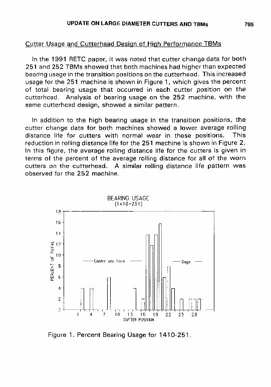
In the 1991 RETC paper, it was noted that cutter change data for both251 and 252 TBMs showed that both machines had higher than expectedbearing usage in the transition positions on the butterhead. This increasedusage for the 251 machine is shown in Figure 1, which gives the percentof total bearing usage that occurred in each cutter position on thebutterhead. Analysis of bearing usage on the 252 machine, with thesame butterhead design, showed a similar pattern.
In addition to the high bearing usage in the transition positions, thecutter change data for both machines showed a lower average rollingdistance life for cutters with normal wear in these positions. Thisreduction in rolling distance life for the 251 machine is shown in Figure 2.In this figure, the average rolling distance life for the cutters is given interms of the percent of the average rolling distance for all of the worncutters on the butterhead. A similar rolling distance life Pattern wasobserved for the 252 machine.
BEARINGUSAGE(1410-251)
14710131619222528CUTTERPOSITION
Figure 1. Percent Bearing Usage for 1410-251.

786 1993 RETC PROCEEDINGS
CUTTER ROLL DISTANCE(1410-251)
200 ,
180
160 I
14 j 19 22 25CUTTERPOSITION
Figure 2. Percent Average Rolling Distance Life for WornC~tters on 1410-251. -
The increased bearing usage and reduced wear life of the cutters in thetransition positions is attributed to higher than average loads on thecutters. One reason for this was that the initial cutter change proceduresallowed cutters with new rings to be placed in positions adjacent tocutters with highly worn rings. This produced high loads on the newcutters because of their greater penetration into the rock during boring.To rectify this problem new cutter change procedures were implementedwhich required the cutters in both the transition and gage positions to bechanged when the difference in the height of adjacent rings reached amaximum value. This procedure was successful in reducing the bearingusage at both machine sites and has been used on all high performanceTBMs, Since that time it has also been determined that some of the earlyhigh bearing usage on these two machines was due to the use ofdefective bearings with soft rollers.
The increased cutter wear rate wear in the transition positions,however, suggests that the butterhead design may have also contributedto the higher loads on the transition cutters. This hypothesis was testedin the field by measuring the cutter loads on selected cutters using strain

UPDATE ON LARGE DIAMETER CUTTERS AND TBMs 787
gages mounted on the cutter shafts, It was also tested by calculating thetheoretical cutter loads for the 251 and 252 butterhead design usingcutter load models developed within The Robbins Company. The resultsof both the field measurements and the model calculations is shown inFigure 3. It is clear from this figure that both the measurements and themodel support the view that higher cutter loads existed in the transitionpositions than in the other positions on the head.
CALCULATED VS MEASUREDCUTTER LOADS(1410-251)
70 ~A
60/ \
20 ‘ I
I
lo~O24681OI2141618 202224262830
CUTTERPOSITION
Figure 3. Calculated and Field Measured Cutter Loads for1410-251.
Based on the cutter usage data for the 251 and 252 machines, changeswere made in the butterhead designs for the 257 and 261 TBMs toreduced the cutter loads in the transition positions, The effect of these
changes on the calculated cutter loads for the 261 machine is shown inFigure 4. On this graph, the cutter loads are given as the percent of theaverage cutter load for the entire butterhead.
In contrast to the cutter load profile for the 251/252 butterhead (Figure3), the 261 profile shows an even cutter load distribution for both theface and gage cutters, The effect of this profile design on the bearingusage for the 261 machine is shown in Figure 5. It is clear from thisfigure, that a nearly random distribution of bearing usage occurred on thebutterhead. In addition, the total bearing usage was greatly reduced.

788
120
100
80u0cc0
: 60><R
40
20
0
1993 RETC PROCEEDINGS
THEORETICALFORCEPROFILE(152-261)
—nmmn
1
.-
ICUTTERPOSlTi3N
)
Figure 4. Calculated Cutter Loads as Percent AverageLoad for 152-261.
BEARINGUSAGE(152-261)
“~
7 13 16 19 22 25CUTTERPOSITION
Figure 5. Percent Bearing Usage for 152-261

UPDATE ON LARGE DIAMETER CUITERS AND TBMs 789
Analysis of the rolling distance life for worn cutters on the 261machine, however, showed that the rolling distance life of the gagecutters was lower than that of the both face and transition cutters. Thiscan be partially explained by the fact that these cutters skid more thanother cutters because they cut a helical path and it may be related to thefact that they pass through broken rock in the invert. In addition, thereis a lower wear allowance in these positions. . Along with these
contributing factors, it was believed that the increased wear rate of thesecutters was related to the high loads on the cutters as predicted by thetheoretical load calculations,
In the design of the butterhead for the 265 TBM, modifications weremade in the location of the gage cutters so that the calculated loads inthese positions would gradually decrease outward. The distribution of thetheoretical cutter loads for this butterhead design is shown in Figure 6.
THEORETICALFORCE PROFILE(1215-265)
““~120-
1oo-
Ld
: 80-.v$ 60-1<
40-
20-
o~1
Figure 6. Calculated Cutter Loads as Percent Average Cutter Load for 1215-265.

790 1993 RETC PROCEEDINGS
The result of this new butterhead design on the bearing usage for the265 machine is shown in Figure 7, and on the average cutter rollingdistance life in Figure 8. Although two cutters in the transition positionsshow higher than normal bearing usage, the overall pattern of bearingusage on the 265 machine is much more evenly distributed than on the251 and 252 machines. The number of costly interruptions to changeblocked cutters was greatly reduced.
As expected, the average rolling distance life of the cutters increasedacross the butterhead and reached its maximum value in the outside gagepositions. This resulted in fewer cutter changes in these positions, whereremoving the cutters is more difficult and time consuming than changingface cutters. It also indicates that the normal loads on the cutters may bethe most important factor in determining the rate of cutter ring wear in thegage positions.
BEARINGUSAGE(1215-265)
181
16 I
14I
CUTTERPOSITION
1,nnn22 25
Figure 7. Percent Bearing Usage for 1215-265,

UPDATE ON LARGE DIAMETER CUTTERS AND TBMs
CUTTER ROLL DISTANCE(1215-265)
791
1 4,
r
,0 13CUTTERPOSITION
Figure 8. Percent Average Rolling Distance Life for WornCutters on 1215-265,
Cutter Housinq lmDrovements.
The wedge lock cutter housing design has also proven far superior tothe older V-Block style housings. The costs, for housing bolts andhousings have dropped by about a factor of ten. The problem of brokenand loose bolts has been virtually eliminated. It is noteworthy, that nota single housing has had to be replaced on all of the six projects. Itshould be pointed out that never before has so much tunnel been boredwithout having to replace housings. This has resulted in much time andmoney being saved by the contractors. The reason for this improvementis the isolation of the housing bolts from the severe cutter loads by meansof a wedge clamping the shaft to the housing, This prevents the boltsfrom breaking and the housings from destruction. The wedge lock designcan also be used on back loading housing designs and is currently offeredfor both the 432 and 483 mm cutters.
Cutter Chanaes
When the 4f33mm diameter cutter was first introduced, it was fearedthat cutter change time would be unacceptably high, This has proven not

792 1993 RETC PROCEEDINGS
to be the case, with the cutter change time ranging between 20 and 50minutes depending on the cutter position and, more importantly, the skilland motivation of the changing crew. This short cutter change time forlarge diameter cutters was made possible by the ingenuity of the 251 and252 crews who developed a simple, safe and rugged cutter changingsystem. Experience has shown that the most efficient cutter changesystems come from the people who actually change the cutters and notfrom the drawing board. In underground excavation, it is most often thesimple systems that work the best while more elaborate and complexsystems get abandoned.
Summary and Conclusions.
This paper has illustrated that over the course of the design andoperation of the five HP TBMs, continuous development has been takingplace. Most of the development effort has been focused on the actualrock cutting aspects of the machines and on the design of the butterhead.
There has also been, and continues to be, research focused on thecutters. The cutters essentially consist of the hub assembly and the discring. During the course of some 49 km bored, it is apparent that the hubassemblies, i.e. the bearings, seals, shafts and hubs, have performedmuch better than older generation cutters. Problems in these areas occurmuch less frequently and overall these assemblies are very reliable.
The cutter ring itself, is where the next gains are likely to be made.There is continued effort in researching materials and processes that fulfillthe paradoxical requirements of hardness and toughness. Various ringgeometries are also being investigated for the optimum ring profile, Thisdevelopment might be the topic of a separate paper and will not becovered any further in this discussion.
To summarize, the role of butterhead profiles and how the resultingloads influence cutter and machine performance has been discussed andit is evident that gains have been made and our understanding of the most
influential factors continues to grow. It is anticipated that this knowledgewill benefit the next HP machines to be built. We can safely say that anew generation of TBMs has arrived and these machines have proven theircapabilities in comparison to their older counterparts. However, furtherwork remains to be done to optimize the performance of these machinesin terms of advance rates and cutter costs. These tasks are continuallybeing worked on.


![Références Super 4 pour QR Codeaa-boschap-fr.resource.bosch.com/...qr/...qr_code.pdf · Lanos 1.4 i (A14SMS [E-TEC]) 04.97 09.03 ... (146 A.048) 09.89 09.92 50 (146 A4.044) 01.86](https://img.dokumen.tips/doc/110x75/5e2ef3aeb47a17467809461e/rfrences-super-4-pour-qr-codeaa-boschap-fr-lanos-14-i-a14sms-e-tec-0497.jpg)