Embed Size (px)
Citation preview
OBD II
Chapter 14
Pg 433 Classroom Manual

What is OBD II ?
• On Board Diagnostics II
• Response to Federal Government
• Monitors when emissions increase by 50% percent or more.
• Calls for standard service procedure without dedicated special tools.
• Universal Diagnostic Test connector
• Standard list of Diagnostic Trouble codes
433 Class manual

OBD II MONITORS
• Catalyst Efficiency Monitor (437C)
• Misfire Monitor (438C)
• Fuel System Monitor (440C)
• Heated Oxygen Sensor Monitor (440C)
• EGR System Monitor (441C)
• Evaporative Emission System Monitor (442C)
• Secondary Air Injection System Monitor (442C)
• Comprehensive Monitor (444C)
Page 436C

Catalyst Efficiency Monitor (437C)
• PCM monitors Oxygen sensors before catalyst and after catalyst
• Downstream sensors internal heater only turn on after engine is warm
• Catalyst stores oxygen and creates a low frequency signal
• If downstream O2 sensor signal reaches a certain frequency, DTC is set in memory

Misfire Monitor (438C)
• If cylinder misfires, HC goes into cat and catalytic converter tries to convert and overworks itself.
• Type A misfire - immediate catalyst damage
• Type B misfire - cause emissions to rise 1.5 times the design standard
• Type C misfire - could cause a I/M failure

Fuel System Monitor (440C)
• Monitors air/fuel ratio in closed loop
• Short term fuel trim - Block Integrator is a short term correction of fuel delivery
• Long term fuel trim - Block Learn is a long term correction of fuel delivery
• If two drive cycle fuel trim corrections occur, PCM will set a DTC and illuminate the MIL.

Heated Oxygen Sensor Monitor (440C)
• OBDII systems have primary and secondary Oxygen sensors
• Monitors O2 sensor switching times
• All O2’s are monitored once per drive cycle
• PCM will vary fuel delivery and look for O2 sensor response
• PCM must see O2 sensors signal within a certain range

EGR System Monitor (441C)
• PCM monitors EGR operation by looking at MAP, or EGR temp, Delta pressure feedback sensor, etc.
• Operated once per OBDII trip
• If EGR pressure or temp is just a little out of range, will set a code
• If two drive cycles, will turn on MIL

Non- Enhanced Evaporative Emission System Monitor (442C)
• Monitors ability of fuel tank to hold vapors and ability of system to purge vapors
• System uses purge flow sensor
• Some systems use a Vapor Management Valve (VMV)

Enhanced EVAP System
• EVAP Operation– Power up Vac Test
– Excess Vac Test
– Loaded Canister Test
– Weak Vac Test
– Small Leak Test
– Purge Solenoid Test
• Should detect a .040 leak.
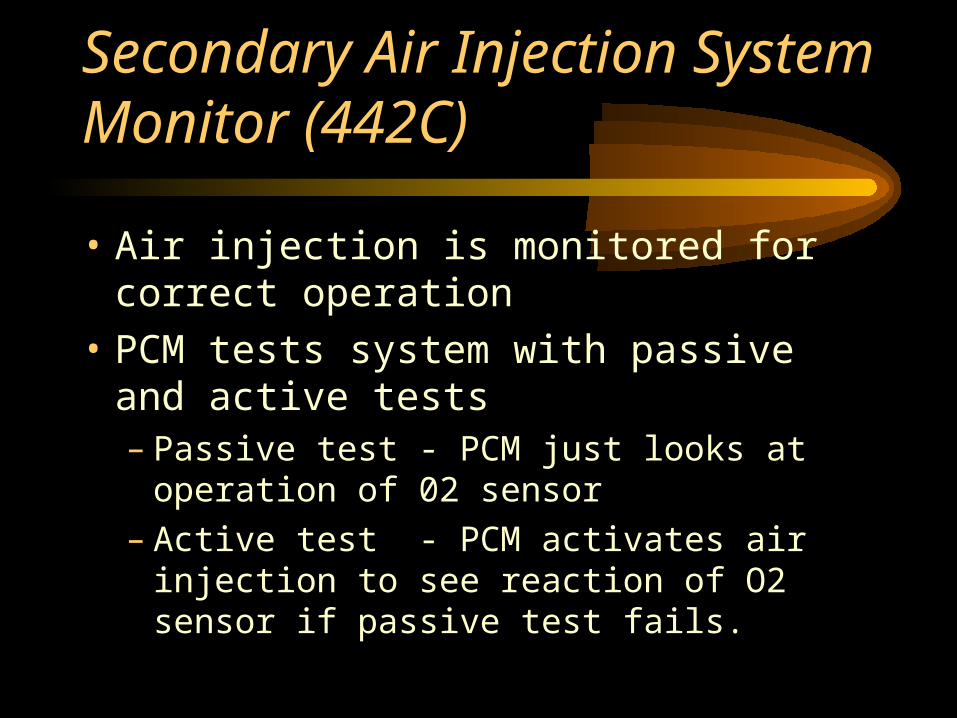
Secondary Air Injection System Monitor (442C)
• Air injection is monitored for correct operation
• PCM tests system with passive and active tests– Passive test - PCM just looks at operation of 02
sensor– Active test - PCM activates air injection to see
reaction of O2 sensor if passive test fails.

Comprehensive Monitor (444C)
• PCM monitors opens, shorts or input signal values that are out of range
• PCM checks voltage levels of inputs
• PCM checks frequency signals by performing rationality tests– Looks at sensor readings to check if make sense
• Output state test - monitors output voltages

SYSTEM READINESS MODE
• Warm Up Cycle - Engine Must rise at least 40 degrees and reach 160 deg.
• Trip - Says at least five monitors must occur (not catalyst efficiency)
• Drive Cycle - Says five monitors plus catalyst efficiency must occur
PAGE 446C

OBD II TRIP
• ….Is when 5 monitors are completed.
• Misfire, Fuel, Comprehensive, EGR and HO2S.
• Each monitor requires specific driving conditions. (some once, some continuously)
• Scanner will tell you when a Trip is completed.
PAGE 446C
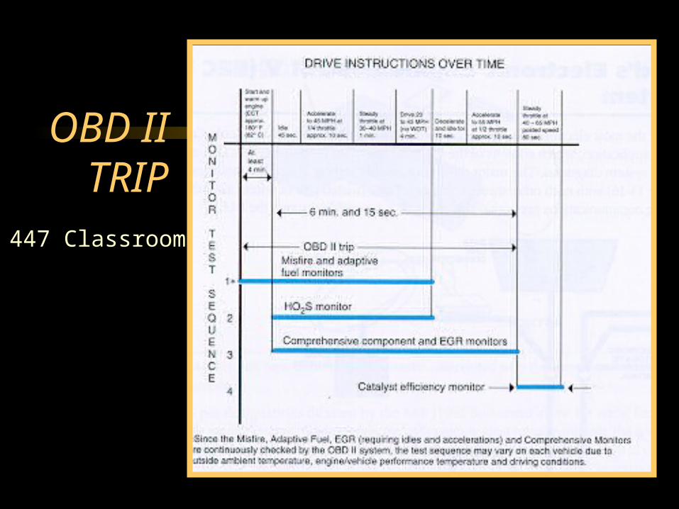
OBD II TRIP
447 Classroom

DRIVE CYCLE
• ….is when all five plus catalyst monitor is completed
• If same fault detected during two drive cycles, DTC is stored
• If misfire occurs, will store code and turn on MIL immediately
• If catalyst monitor detects a fault in three drive cycles, it will set a code
• All faults erased after 40 ign. cycles

OBD II DRIVE CYCLE447 Classroom

Data Link Connector (DLC)
• Mounted in standard location
• 16 pin with 9 pins defined by SAE
• Cannot jump across any pins to display codes on MIL
• Any Scanner should access Data StreamPg 450 Classroom

LOCATION OF DLC
• Must be accessible from drivers seat
• Must be located between left of center and 300 millimeters to the right of center
• Must not be hidden• 9 Pins OBDII• 7 Pins Manufacturer

PCM Communication
• Federal regulations mandate common communication system
• OBDII systems use bi-directional communication• Scanner can access data from any vehicle sold in the United
States
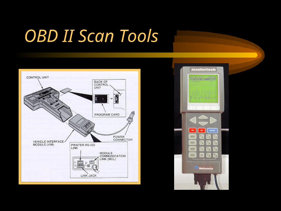
OBD II Scan Tools

OBD II Programming• EEPROM Programming
– Direct Programming• Hooked directly from a PC to vehicle DLC
– Remote Programming• Connected from PC to Scanner to DLC
• Scanner acts as a intermediary with Mass Storage Cartridge
– Off-Board Programming• Used away from vehicle.
• Requires a Programming Adapter

OBD II DIAGNOSIS
• Diagnostic systems will be standardized– Scanners– Codes– Terminology– Locations of DLC’s– Testing of Engine Control Systems– Trouble code standardization

Diagnostic Trouble Codes (DTC’s)
• SAE J2012 specify format
• First Digit Area where code belongs:– P - Powertrain– B - Body– C - Chassis
• Second Digit Who’s Responsible– 0 - SAE– 1 - Manufacturer

DTC’s• Third Digit - Subgroup
– 0 - Total System– 1 - Fuel-air control– 2 - Fuel-air control– 3 - Ignition System misfire– 4 - Auxiliary Emission Systems– 5 - Idle Speed Control– 6 - PCM and Input/Output– 7 - Transmission– 8 - Non-EEC Powertrain

DTC’s
• Fourth and Fifth digits - Specific Area where trouble exists
• EXAMPLE: P1711– P - Powertrain DTC– 1 - Manufacturer defined code– 7 - Transmission Subgroup– 11- Transmission oil temp (TOT) sensor and
related circuit

OBD II Diagnostic Codes

SCANNER OPTIONS
• Some scanners have built in printer• Some scanners have graph or lab scope
capabilities• Most scanners have “freeze” mode• Some scanners have diagnostic information
available such as common problems, technical service bulletins ref.
• Engine Analyzers have scanners also

TEST SELECTIONS
• Fault Codes• Switch Tests• ATM Tests• Sensor Tests• AIS Tests• Output State Tests• EMR reset• Wiggle Test
• KOEO Test• KOER Test• Computed Timing• Clear Memory• Code Library• Basic Test• CDR Test• Cruise Control Test

FREEZE FRAME MODE
• Federal Regulations require engine operating conditions be captured whenever a MIL is illuminated.
• The latest failure will always overwrite a previous failure except misfire or fuel trim malfunctions.
• Some scanners will print out a graph showing sensor malfunctioning sensor signals
Pg 609 Lab Manual


