Embed Size (px)
Citation preview
8/7/2019 Ch03_the Structure of Metals
http://slidepdf.com/reader/full/ch03the-structure-of-metals 1/40
1
ISSUES TO ADDRESS...
• How do atoms assemble into solid structures?
(for now, focus on metals)
• How does the density of a material depend on
its structure?
• When do material properties vary with the
sample (i.e., part) orientation?
Chapter 3: The Structures of Metals

8/7/2019 Ch03_the Structure of Metals
http://slidepdf.com/reader/full/ch03the-structure-of-metals 2/40
2
• Non dense, random packing
• Dense, ordered packing
Dense, ordered packed structures tend to have
lower energies.
Energy and Packing
Energy
r
typical neighbor bond length
typical neighbor bond energy
Energy
r
typical neighbor bond length
typical neighbor bond energy
8/7/2019 Ch03_the Structure of Metals
http://slidepdf.com/reader/full/ch03the-structure-of-metals 3/40
3
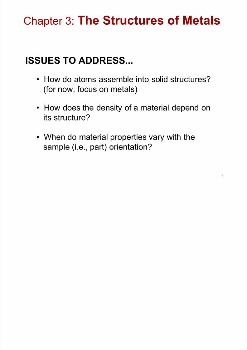
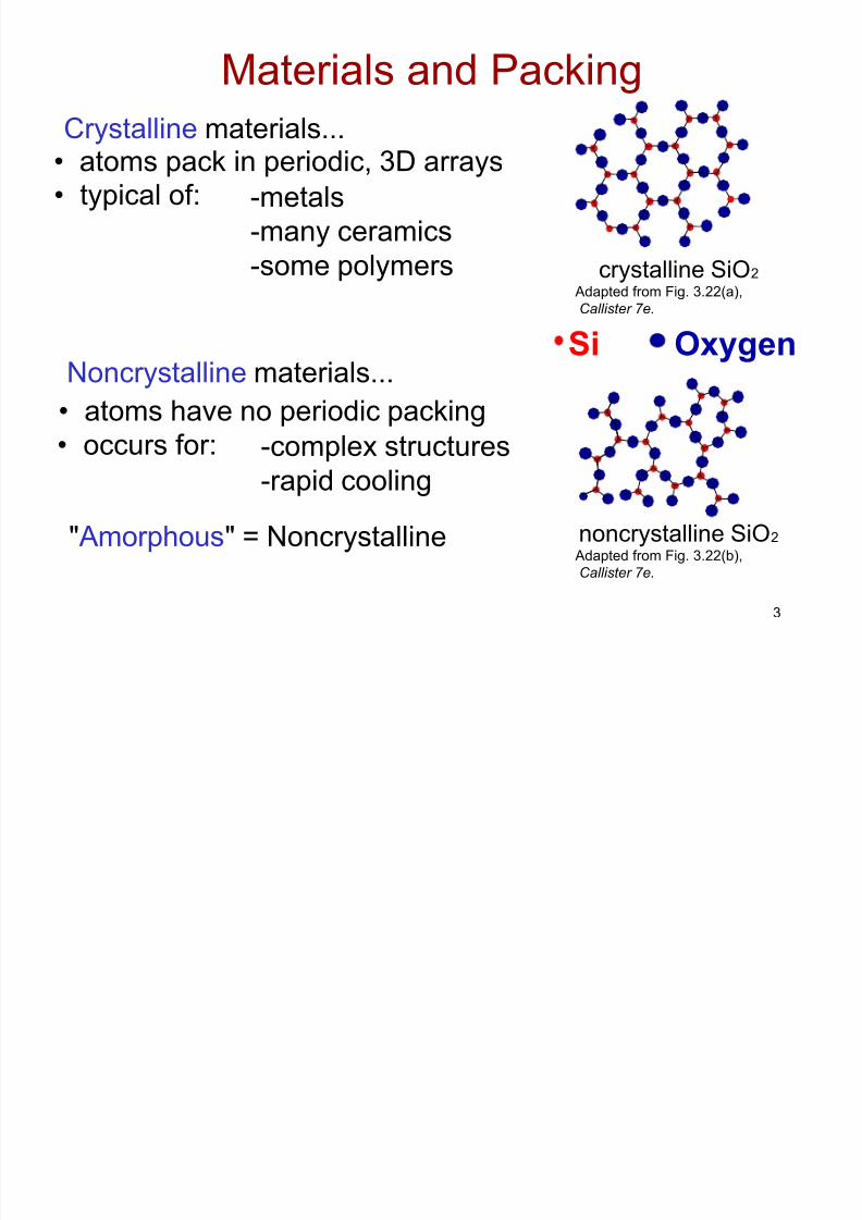
• atoms pack in periodic, 3D arraysCrystalline materials...
-metals
-many ceramics
-some polymers
• atoms have no periodic packing
Noncrystalline materials...
-complex structures-rapid cooling
crystalline SiO2
noncrystalline SiO2"Amorphous" = NoncrystallineAdapted from Fig. 3.22(b),
Callister 7e.
Adapted from Fig. 3.22(a),
Callister 7e.
Materials and Packing
Si Oxygen
• typical of:
• occurs for:
8/7/2019 Ch03_the Structure of Metals
http://slidepdf.com/reader/full/ch03the-structure-of-metals 4/40
4
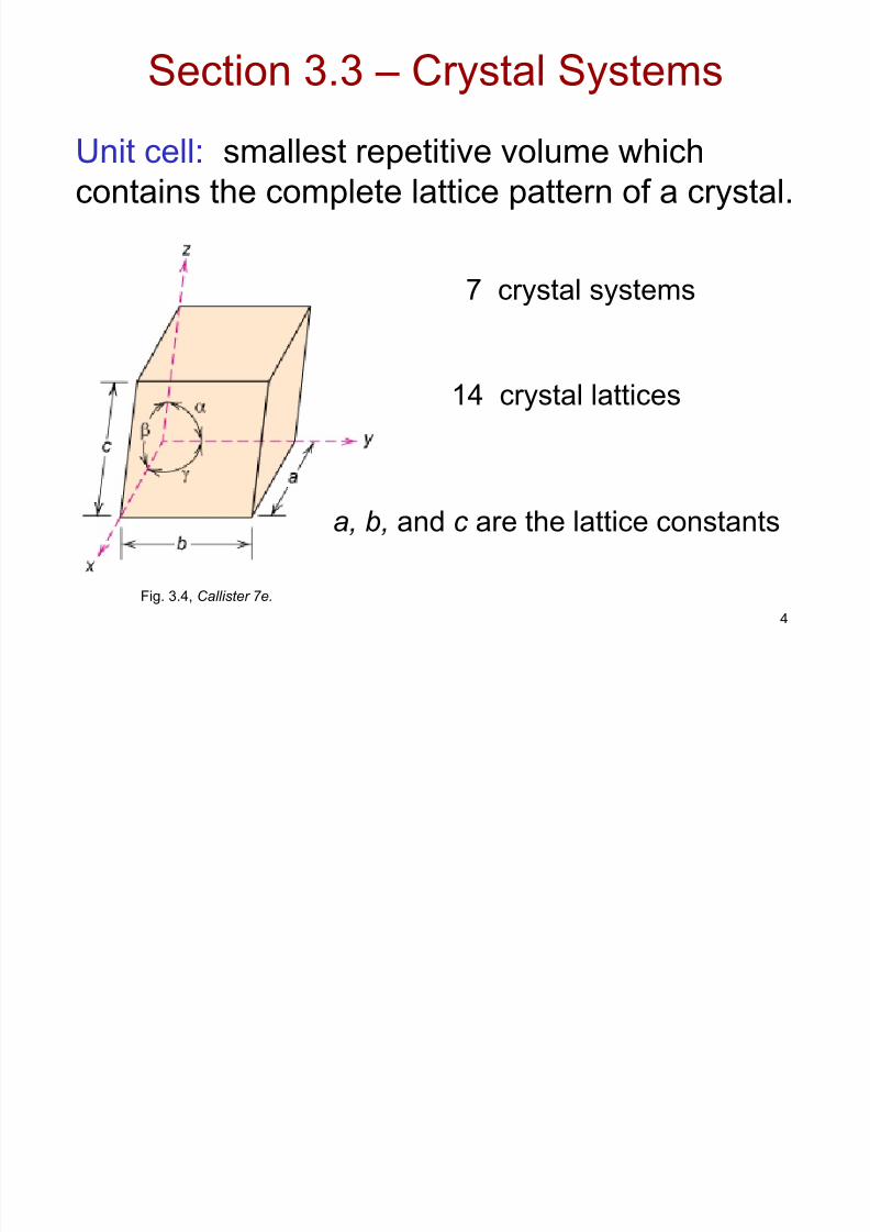
Section 3.3 – Crystal Systems
7 crystal systems
14 crystal lattices
Fig. 3.4, Callister 7e.
Unit cell: smallest repetitive volume whichcontains the complete lattice pattern of a crystal.
a, b, and c are the lattice constants

8/7/2019 Ch03_the Structure of Metals
http://slidepdf.com/reader/full/ch03the-structure-of-metals 5/40
8/7/2019 Ch03_the Structure of Metals
http://slidepdf.com/reader/full/ch03the-structure-of-metals 6/40
6
• Tend to be densely packed.• Reasons for dense packing:
- Typically, only one element is present, so all atomic
radii are the same.
- Metallic bonding is not directional.
- Nearest neighbor distances tend to be small in
order to lower bond energy.
- Electron cloud shields cores from each other
• Have the simplest crystal structures.
We will examine three such structures...
Metallic Crystal Structures
8/7/2019 Ch03_the Structure of Metals
http://slidepdf.com/reader/full/ch03the-structure-of-metals 7/40
7
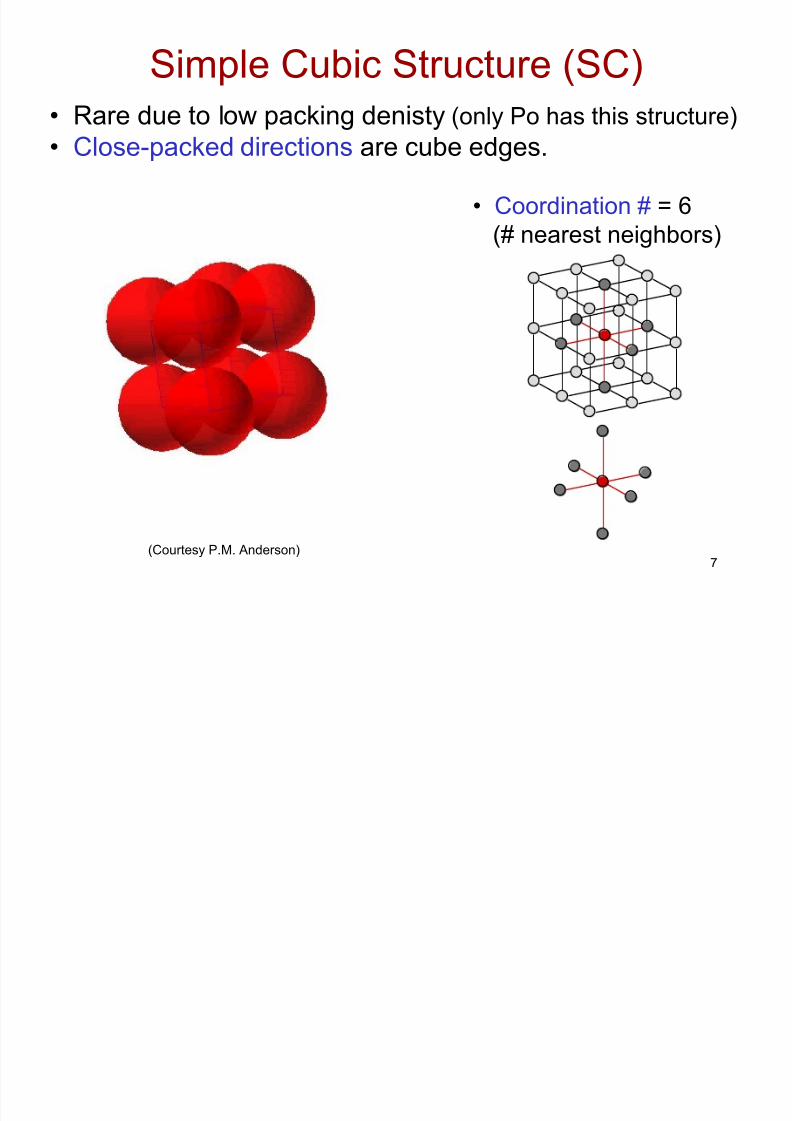
• Rare due to low packing denisty (only Po has this structure)
• Close-packed directions are cube edges.
• Coordination # = 6
(# nearest neighbors)
(Courtesy P.M. Anderson)
Simple Cubic Structure (SC)
8/7/2019 Ch03_the Structure of Metals
http://slidepdf.com/reader/full/ch03the-structure-of-metals 8/40
8
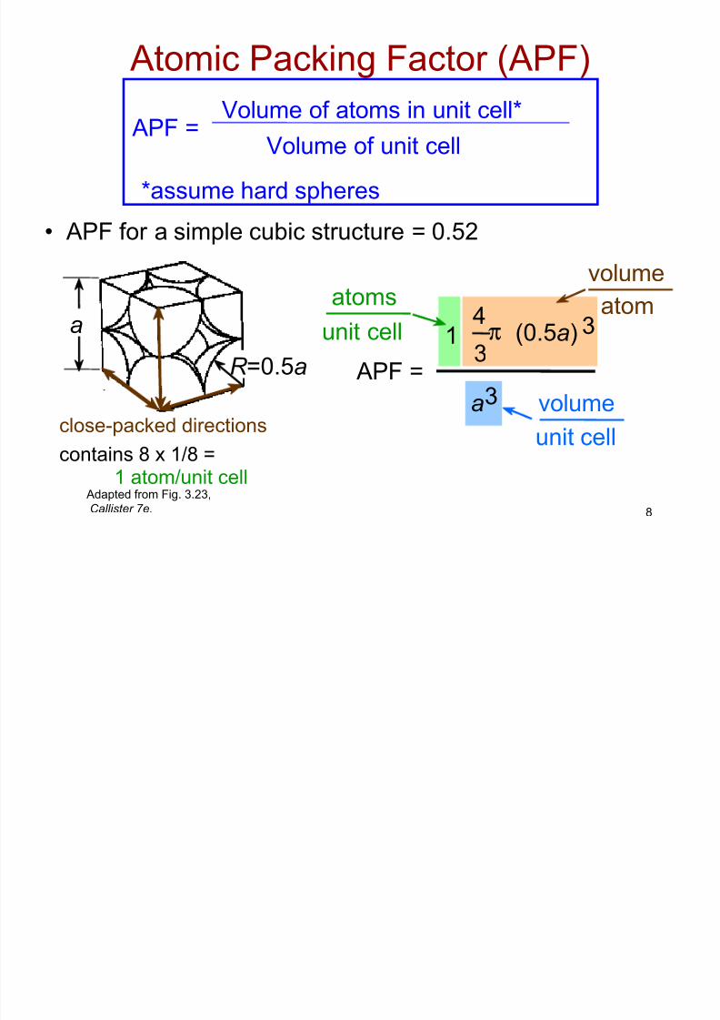
• APF for a simple cubic structure = 0.52
APF =a3
4
3π (0.5a) 31
atoms
unit cellatom
volume
unit cell
volume
Atomic Packing Factor (APF)
APF =Volume of atoms in unit cell*
Volume of unit cell
*assume hard spheres
Adapted from Fig. 3.23,
Callister 7e.
close-packed directions
a
R =0.5a
contains 8 x 1/8 =1 atom/unit cell
8/7/2019 Ch03_the Structure of Metals
http://slidepdf.com/reader/full/ch03the-structure-of-metals 9/40
9
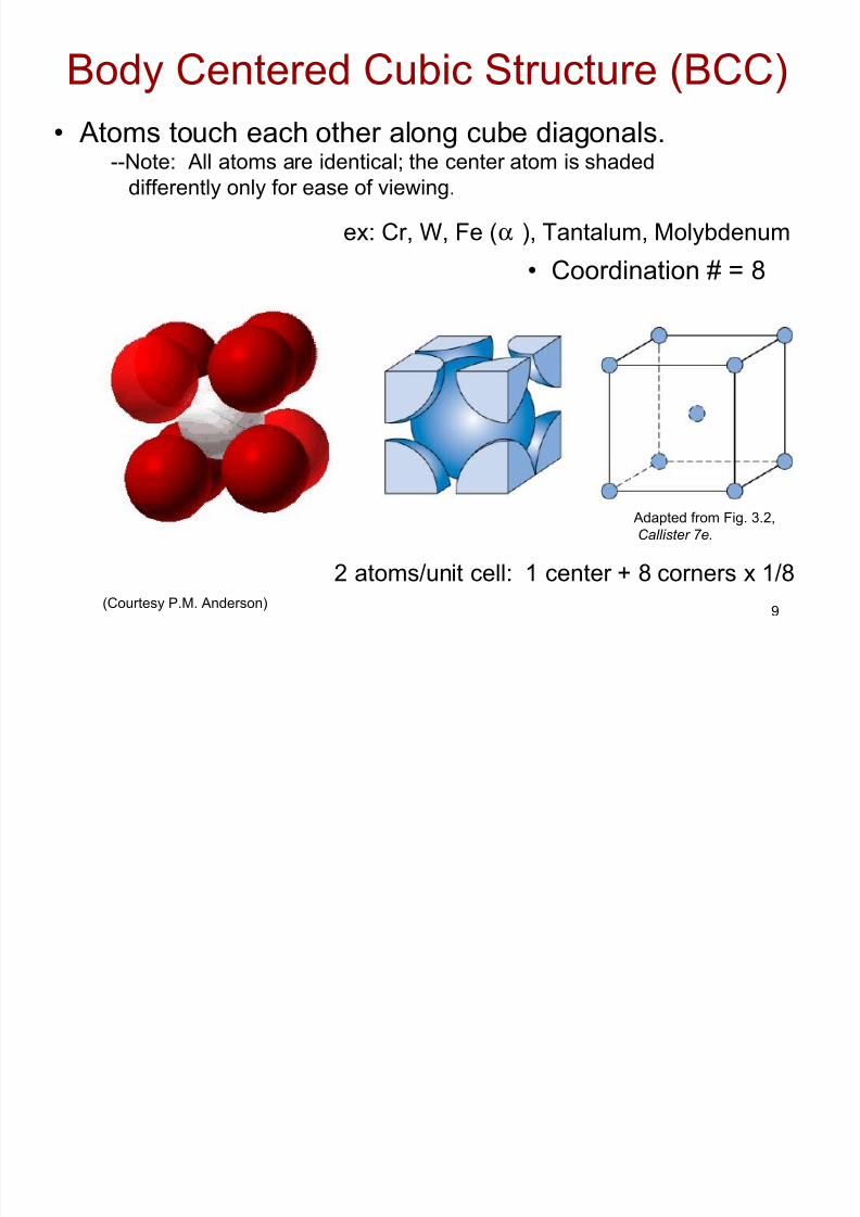
• Coordination # = 8
Adapted from Fig. 3.2,
Callister 7e.
(Courtesy P.M. Anderson)
• Atoms touch each other along cube diagonals.--Note: All atoms are identical; the center atom is shaded
differently only for ease of viewing.
Body Centered Cubic Structure (BCC)
ex: Cr, W, Fe (α ), Tantalum, Molybdenum
2 atoms/unit cell: 1 center + 8 corners x 1/8

8/7/2019 Ch03_the Structure of Metals
http://slidepdf.com/reader/full/ch03the-structure-of-metals 10/40
10
Atomic Packing Factor: BCC
a
APF =
4
3π ( 3a/4)32
atoms
unit cell atom
volume
a3
unit cell
volume
length = 4R =
Close-packed directions:
3 a
• APF for a body-centered cubic structure = 0.68
aR
Adapted from
Fig. 3.2(a), Callister 7e.
a2
a3
8/7/2019 Ch03_the Structure of Metals
http://slidepdf.com/reader/full/ch03the-structure-of-metals 11/40
11
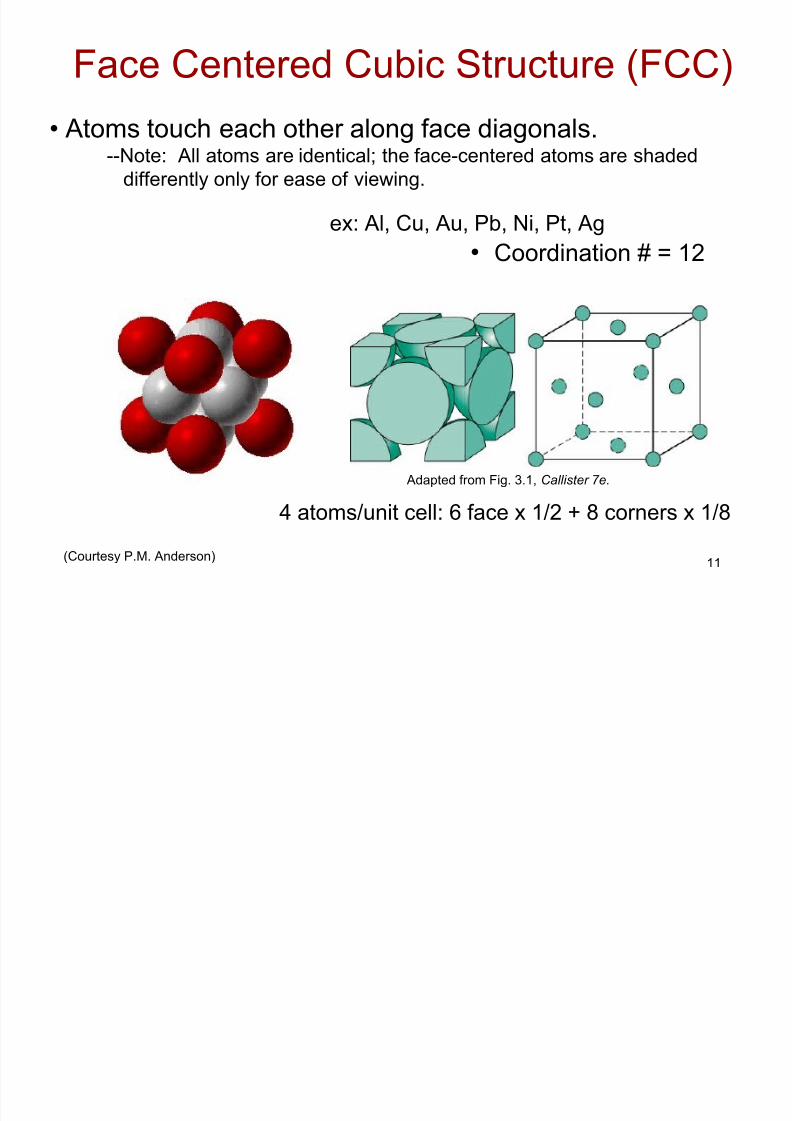
• Coordination # = 12
Adapted from Fig. 3.1, Callister 7e.
(Courtesy P.M. Anderson)
• Atoms touch each other along face diagonals.--Note: All atoms are identical; the face-centered atoms are shaded
differently only for ease of viewing.
Face Centered Cubic Structure (FCC)
ex: Al, Cu, Au, Pb, Ni, Pt, Ag
4 atoms/unit cell: 6 face x 1/2 + 8 corners x 1/8
8/7/2019 Ch03_the Structure of Metals
http://slidepdf.com/reader/full/ch03the-structure-of-metals 12/40
12
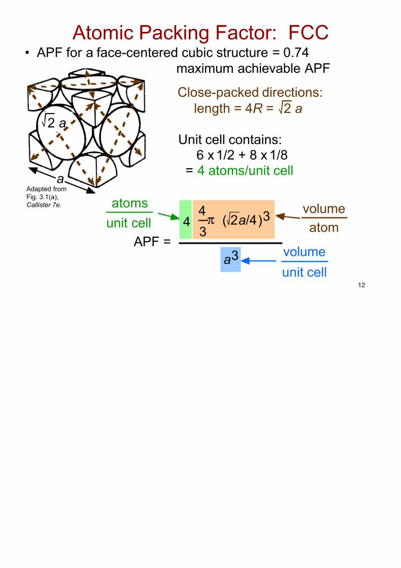
• APF for a face-centered cubic structure = 0.74
Atomic Packing Factor: FCC
maximum achievable APF
APF =
4
3π ( 2a/4)34
atoms
unit cell atomvolume
a3
unit cell
volume
Close-packed directions:
length = 4R = 2 a
Unit cell contains:6 x 1/2 + 8 x 1/8
= 4 atoms/unit cella
2 a
Adapted from
Fig. 3.1(a),
Callister 7e.
8/7/2019 Ch03_the Structure of Metals
http://slidepdf.com/reader/full/ch03the-structure-of-metals 13/40
13
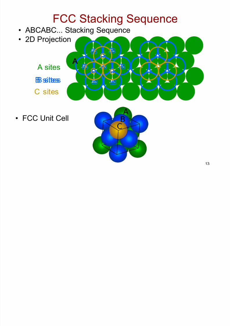
A sites
B B
B
BB
B B
C sites
C C
CA
B
B sites
• ABCABC... Stacking Sequence
• 2D Projection
• FCC Unit Cell
FCC Stacking Sequence
B B
B
BB
B B
B sites
C C
CA
C C
CA
A
BC
8/7/2019 Ch03_the Structure of Metals
http://slidepdf.com/reader/full/ch03the-structure-of-metals 14/40
14
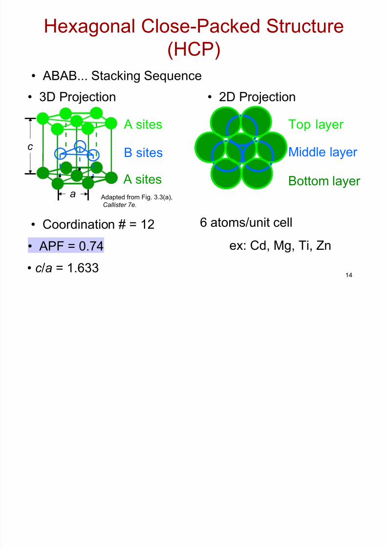
• Coordination # = 12
• ABAB... Stacking Sequence
• APF = 0.74
• 3D Projection • 2D Projection
Adapted from Fig. 3.3(a),
Callister 7e.
Hexagonal Close-Packed Structure
(HCP)
6 atoms/unit cell
ex: Cd, Mg, Ti, Zn
• c /a = 1.633
c
a
A sites
B sites
A sites Bottom layer
Middle layer
Top layer
8/7/2019 Ch03_the Structure of Metals
http://slidepdf.com/reader/full/ch03the-structure-of-metals 15/40
15
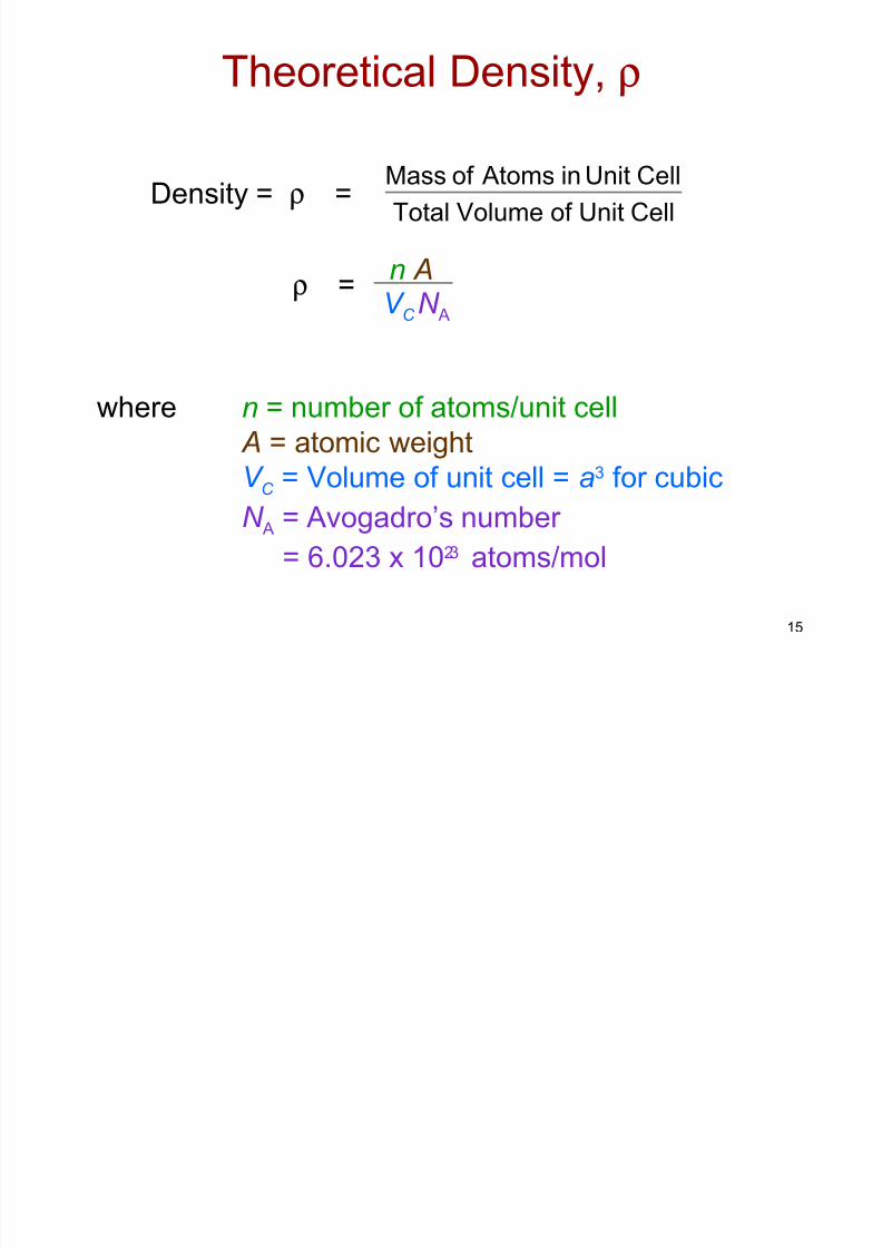
Theoretical Density, ρ
where n = number of atoms/unit cell
A = atomic weight
V C = Volume of unit cell = a3 for cubic
N A = Avogadro’s number
= 6.023 x 10²³ atoms/mol
Density = ρ =
V C N A
n Aρ =
CellUnitof VolumeTotal
CellUnitinAtomsof Mass
8/7/2019 Ch03_the Structure of Metals
http://slidepdf.com/reader/full/ch03the-structure-of-metals 16/40
16
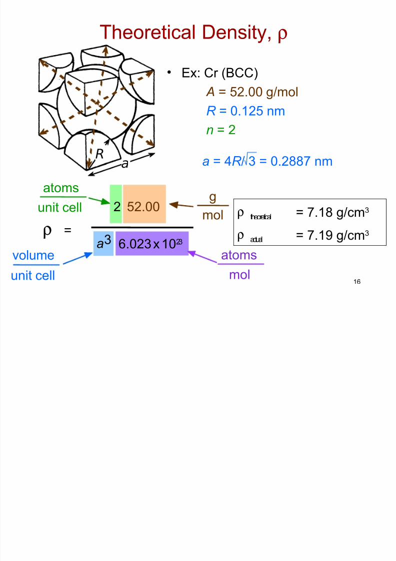
• Ex: Cr (BCC)
A = 52.00 g/mol
R = 0.125 nm
n = 2
ρ theoretical
a = 4R / 3 = 0.2887 nm
ρ actual
aR
ρ =a3
52.002
atoms
unit cell mol
g
unit cell
volume atoms
mol
6.023 x 10²³
Theoretical Density, ρ
= 7.18 g/cm3
= 7.19 g/cm3

8/7/2019 Ch03_the Structure of Metals
http://slidepdf.com/reader/full/ch03the-structure-of-metals 17/40
17
Densities of Material Classes
ρ metals
>ρ ceramics
>ρ polymers
Why?
Data from Table B1, Callister 7e.
ρ
(g/cm
)3
Graphite/Ceramics/
Semicond
Metals/Alloys
Composites/fibers
Polymers
1
2
20
30Based on data in Table B1, Callister
*GFRE, CFRE, & AFRE are Glass,Carbon, & Aramid Fiber-ReinforcedEpoxy composites (values based on60% volume fraction of aligned fibers
in an epoxy matrix).10
3
4
5
0.3
0.4
0.5
Magnesium
Aluminum
Steels
Titanium
Cu,Ni
Tin, Zinc
Silver, Mo
TantalumGold, WPlatinum
Graphite
Silicon
Glass-sodaConcrete
Si nitrideDiamondAl oxide
Zirconia
HDPE, PSPP, LDPE
PC
PTFE
PET
PVCSilicone
Wood
AFRE*
CFRE*
GFRE*
Glass fibers
Carbon fibers
Aramid fibers
Metals have...• close-packing
(metallic bonding)
• often large atomic masses Ceramics have...
• less dense packing
• often lighter elements
Polymers have...
• low packing density(often amorphous)
• lighter elements (C,H,O)
Composites have...• intermediate values
In general
8/7/2019 Ch03_the Structure of Metals
http://slidepdf.com/reader/full/ch03the-structure-of-metals 18/40
18
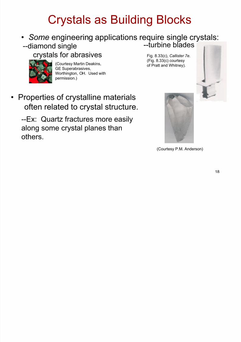
• Some engineering applications require single crystals:
• Properties of crystalline materials
often related to crystal structure.
(Courtesy P.M. Anderson)
--Ex: Quartz fractures more easily
along some crystal planes thanothers.
--diamond single
crystals for abrasives
--turbine blades
Fig. 8.33(c), Callister 7e.
(Fig. 8.33(c) courtesy
of Pratt and Whitney).(Courtesy Martin Deakins,
GE Superabrasives,
Worthington, OH. Used with
permission.)
Crystals as Building Blocks

8/7/2019 Ch03_the Structure of Metals
http://slidepdf.com/reader/full/ch03the-structure-of-metals 19/40
19
• Most engineering materials are polycrystals.
• Nb-Hf-W plate with an electron beam weld.
• Each "grain" is a single crystal.• If grains are randomly oriented,
overall component properties are not directional.
• Grain sizes typ. range from 1 nm to 2 cm
(i.e., from a few to millions of atomic layers).
Adapted from Fig. K,
color inset pages of
Callister 5e.
(Fig. K is courtesy of
Paul E. Danielson,
Teledyne Wah Chang
Albany)
1 mm
Polycrystals
Isotropic
Anisotropic
8/7/2019 Ch03_the Structure of Metals
http://slidepdf.com/reader/full/ch03the-structure-of-metals 20/40
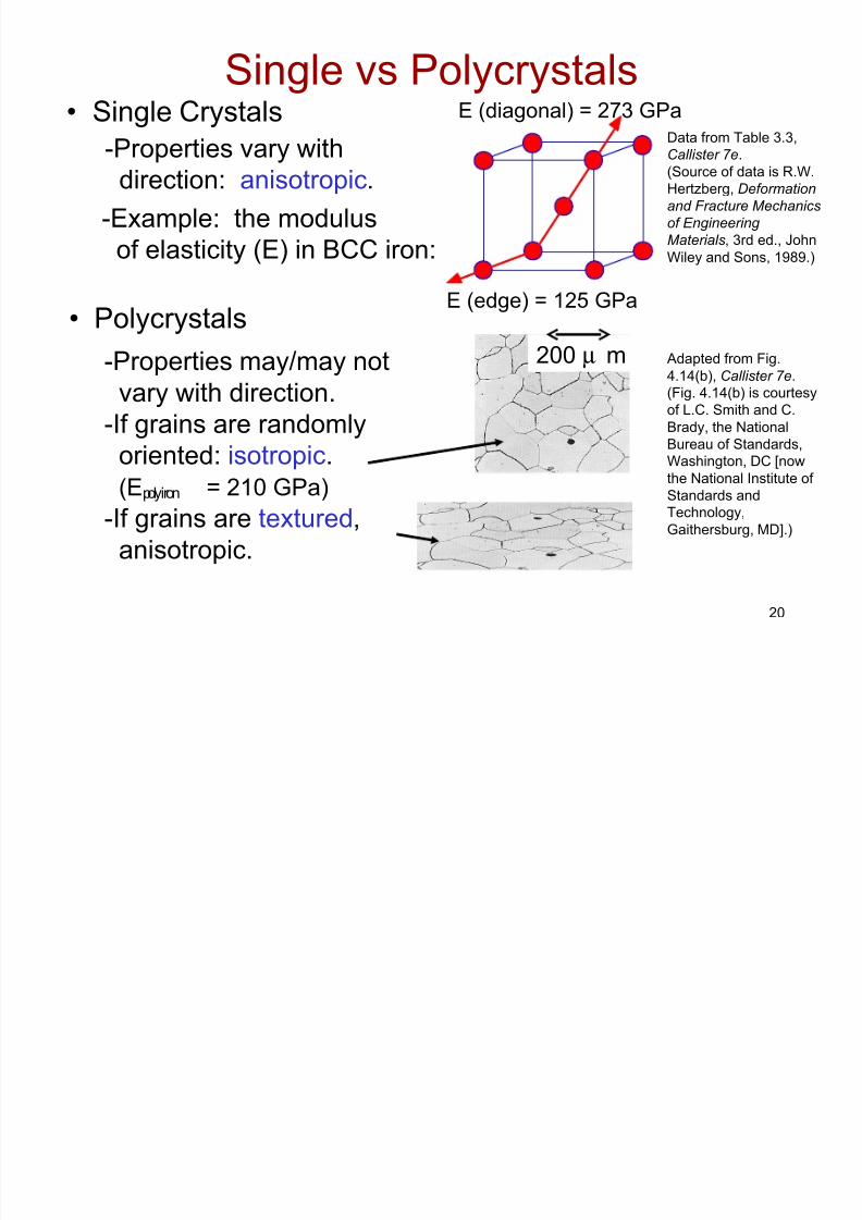
20
• Single Crystals
-Properties vary withdirection: anisotropic.
-Example: the modulus
of elasticity (E) in BCC iron:
• Polycrystals
-Properties may/may not
vary with direction.
-If grains are randomly
oriented: isotropic. (Epoly iron = 210 GPa)
-If grains are textured,
anisotropic.
200 µ m
Data from Table 3.3,
Callister 7e.(Source of data is R.W.
Hertzberg, Deformation
and Fracture Mechanics
of Engineering
Materials, 3rd ed., John
Wiley and Sons, 1989.)
Adapted from Fig.
4.14(b), Callister 7e.
(Fig. 4.14(b) is courtesy
of L.C. Smith and C.
Brady, the National
Bureau of Standards,
Washington, DC [now
the National Institute of
Standards and
Technology,
Gaithersburg, MD].)
Single vs PolycrystalsE (diagonal) = 273 GPa
E (edge) = 125 GPa

8/7/2019 Ch03_the Structure of Metals
http://slidepdf.com/reader/full/ch03the-structure-of-metals 21/40
21
Section 3.6 – Polymorphism
• Two or more distinct crystal structures for the same
material (allotropy/polymorphism)
titanium
α , β -Ti
carbon
diamond, graphite
BCC
FCC
BCC
1538ºC
1394ºC
912ºC
δ -Fe
γ -Fe
α -Fe
liquid
iron system
8/7/2019 Ch03_the Structure of Metals
http://slidepdf.com/reader/full/ch03the-structure-of-metals 22/40
22
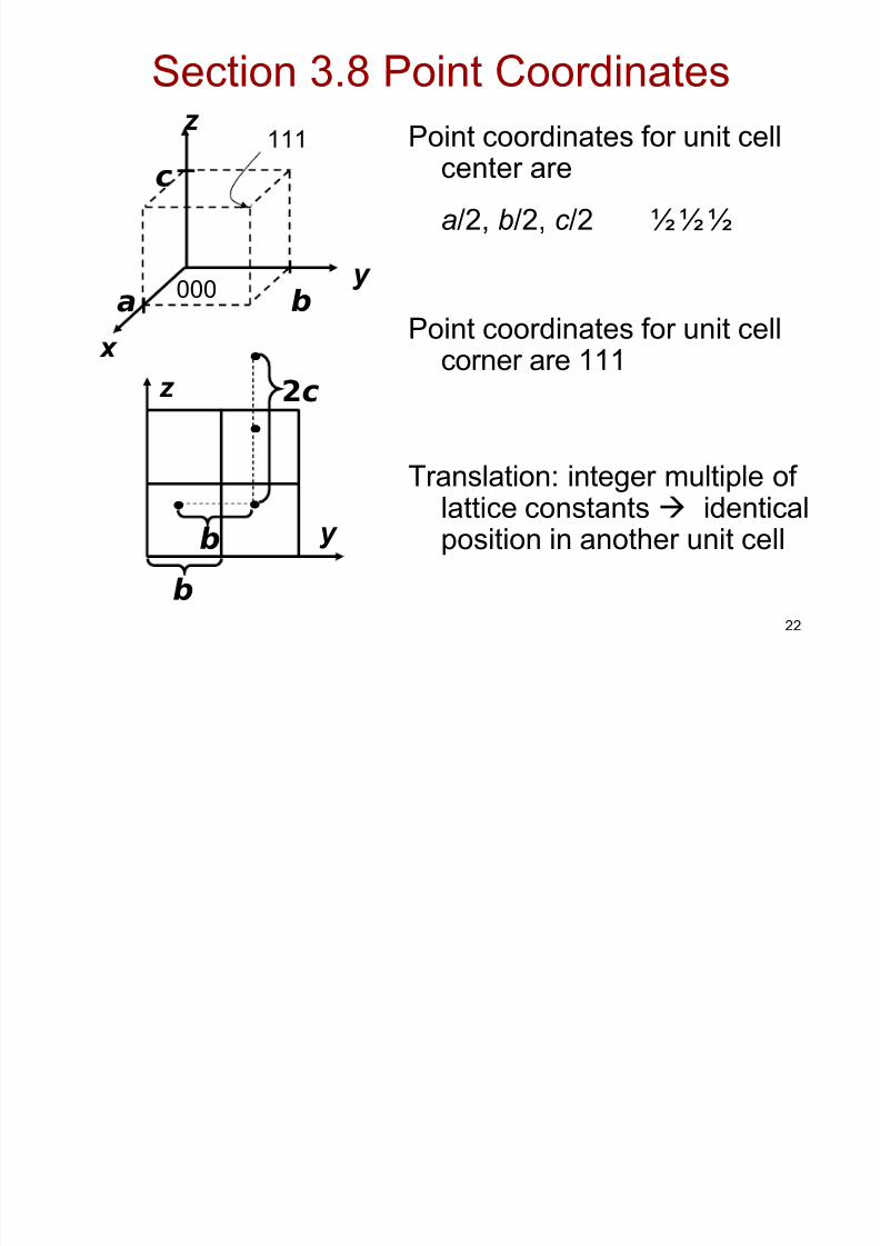
Section 3.8 Point Coordinates
Point coordinates for unit cellcenter are
a/2, b/2, c /2 ½ ½ ½
Point coordinates for unit cellcorner are 111
Translation: integer multiple of lattice constants identicalposition in another unit cell
z
x
y
a b
c
000
111
y
z
•
2c
•
•
•
b
b
8/7/2019 Ch03_the Structure of Metals
http://slidepdf.com/reader/full/ch03the-structure-of-metals 23/40
23
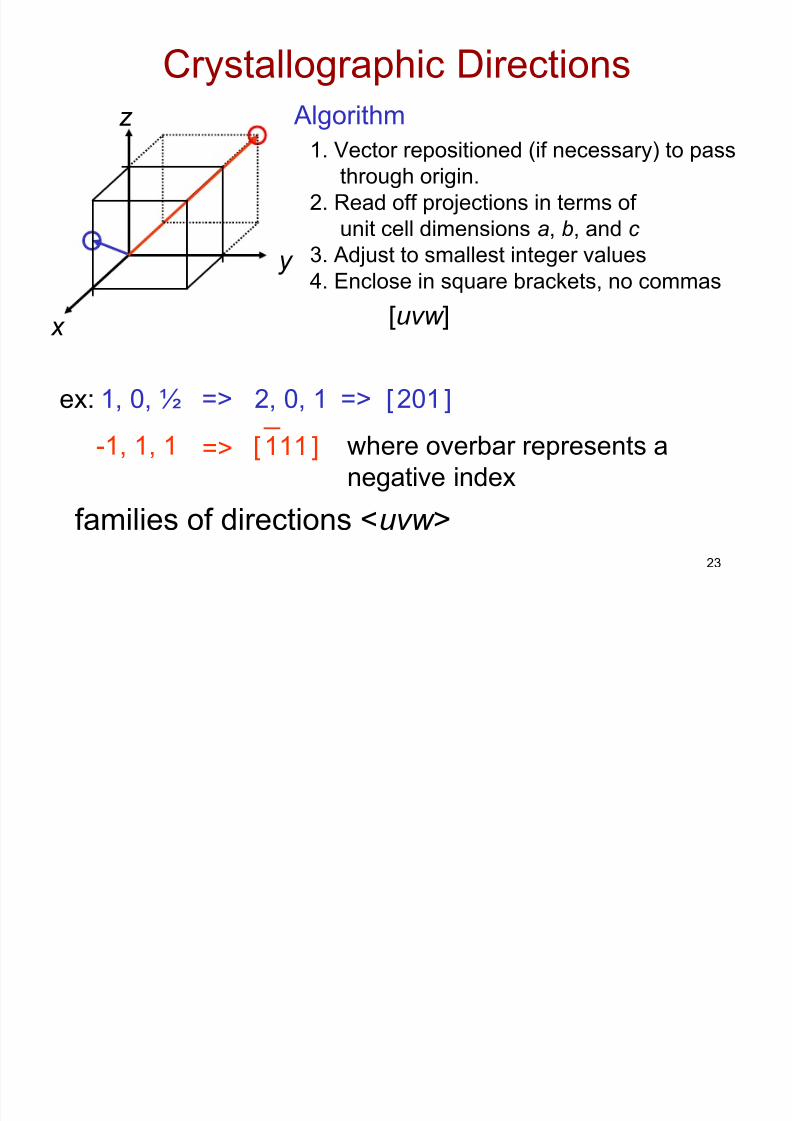
Crystallographic Directions
1. Vector repositioned (if necessary) to pass
through origin.
2. Read off projections in terms of
unit cell dimensions a, b, and c
3. Adjust to smallest integer values
4. Enclose in square brackets, no commas
[uvw ]
ex: 1, 0, ½ => 2, 0, 1 => [ 201 ]
-1, 1, 1
families of directions <uvw >
z
x
Algorithm
where overbar represents a
negative index
[ 111 ]=>
y
8/7/2019 Ch03_the Structure of Metals
http://slidepdf.com/reader/full/ch03the-structure-of-metals 24/40
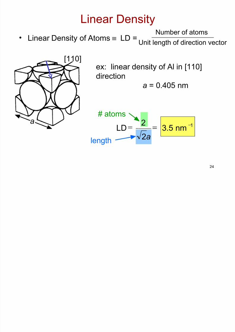
24
ex: linear density of Al in [110]
direction
a = 0.405 nm
Linear Density
•Linear Density of Atoms ≡ LD =
a
[110]
Unit length of direction vector
Number of atoms
# atoms
length
13.5 nma2
2LD −==
8/7/2019 Ch03_the Structure of Metals
http://slidepdf.com/reader/full/ch03the-structure-of-metals 25/40
25
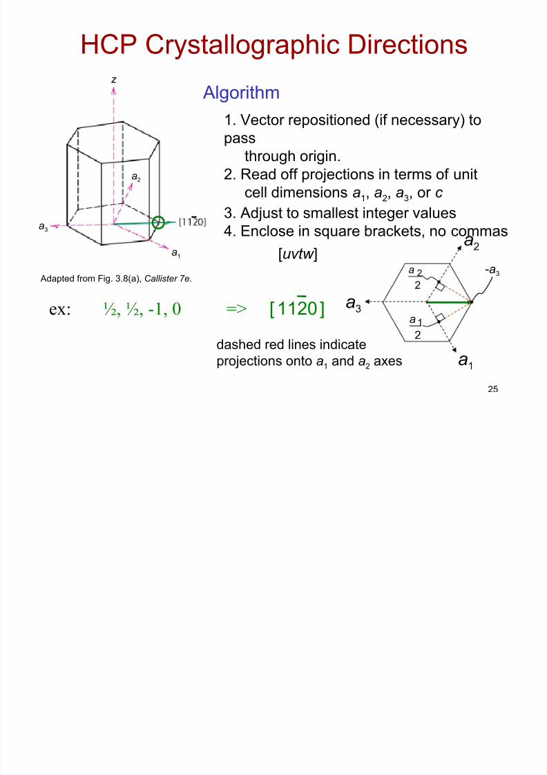
HCP Crystallographic Directions
1. Vector repositioned (if necessary) to
pass
through origin.
2. Read off projections in terms of unit
cell dimensions a1, a2, a3, or c 3. Adjust to smallest integer values
4. Enclose in square brackets, no commas
[uvtw ]
[ 1120 ]ex: ½, ½, -1, 0 =>
Adapted from Fig. 3.8(a), Callister 7e.
dashed red lines indicate
projections onto a1 and a2 axes a1
a2
a3
-a3
2
a 2
2
a 1
-a3
a1
a2
z
Algorithm
8/7/2019 Ch03_the Structure of Metals
http://slidepdf.com/reader/full/ch03the-structure-of-metals 26/40
26
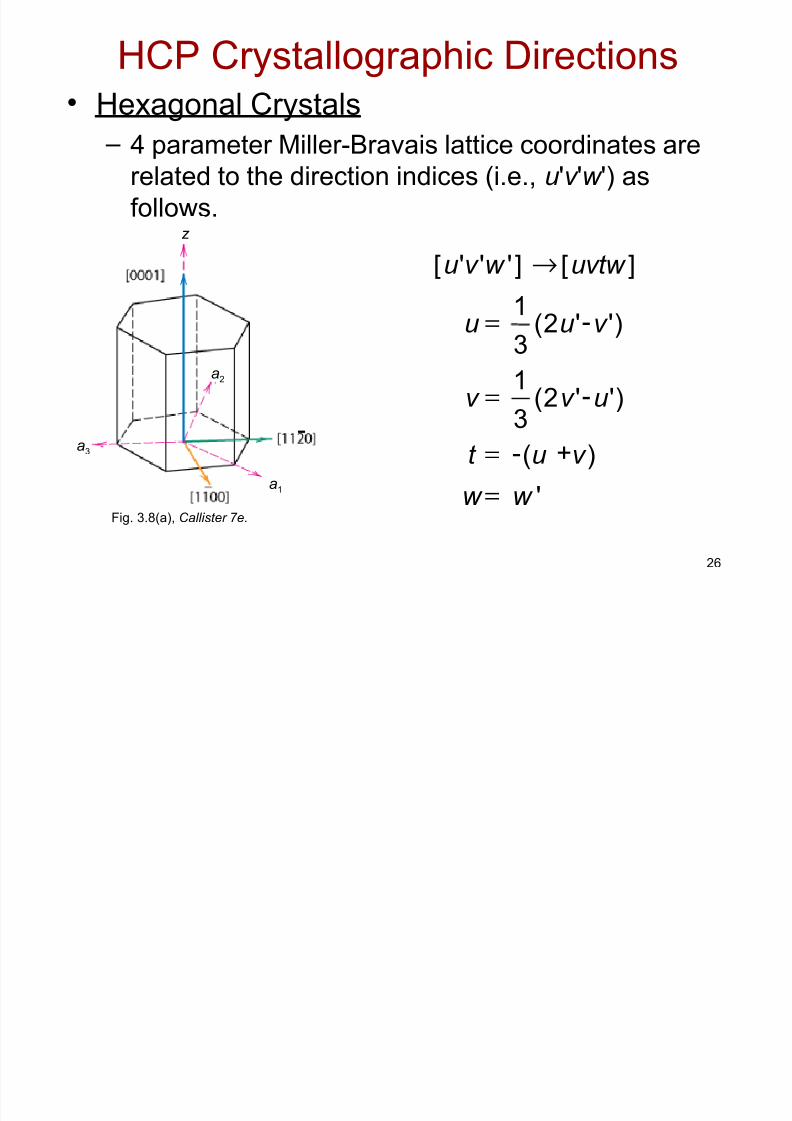
HCP Crystallographic Directions• Hexagonal Crystals
– 4 parameter Miller-Bravais lattice coordinates arerelated to the direction indices (i.e., u 'v 'w ') as
follows.
=
=
=
'w w
t
v
u
)v u ( +-
)'u 'v 2(3
1-
)'v 'u 2(3
1-=
]uvtw []'w 'v 'u [ →
Fig. 3.8(a), Callister 7e.
-a3
a1
a2
z
8/7/2019 Ch03_the Structure of Metals
http://slidepdf.com/reader/full/ch03the-structure-of-metals 27/40
27
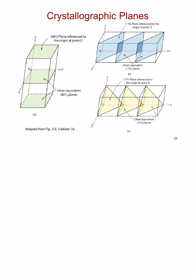
Crystallographic Planes
Adapted from Fig. 3.9, Callister 7e.

8/7/2019 Ch03_the Structure of Metals
http://slidepdf.com/reader/full/ch03the-structure-of-metals 28/40
28
Crystallographic Planes
• Miller Indices: Reciprocals of the (three) axialintercepts for a plane, cleared of fractions &common multiples. All parallel planes havesame Miller indices.
• Algorithm1. Read off intercepts of plane with axes in
terms of a, b, c 2. Take reciprocals of intercepts
3. Reduce to smallest integer values4. Enclose in parentheses, nocommas i.e., (hkl )
8/7/2019 Ch03_the Structure of Metals
http://slidepdf.com/reader/full/ch03the-structure-of-metals 29/40
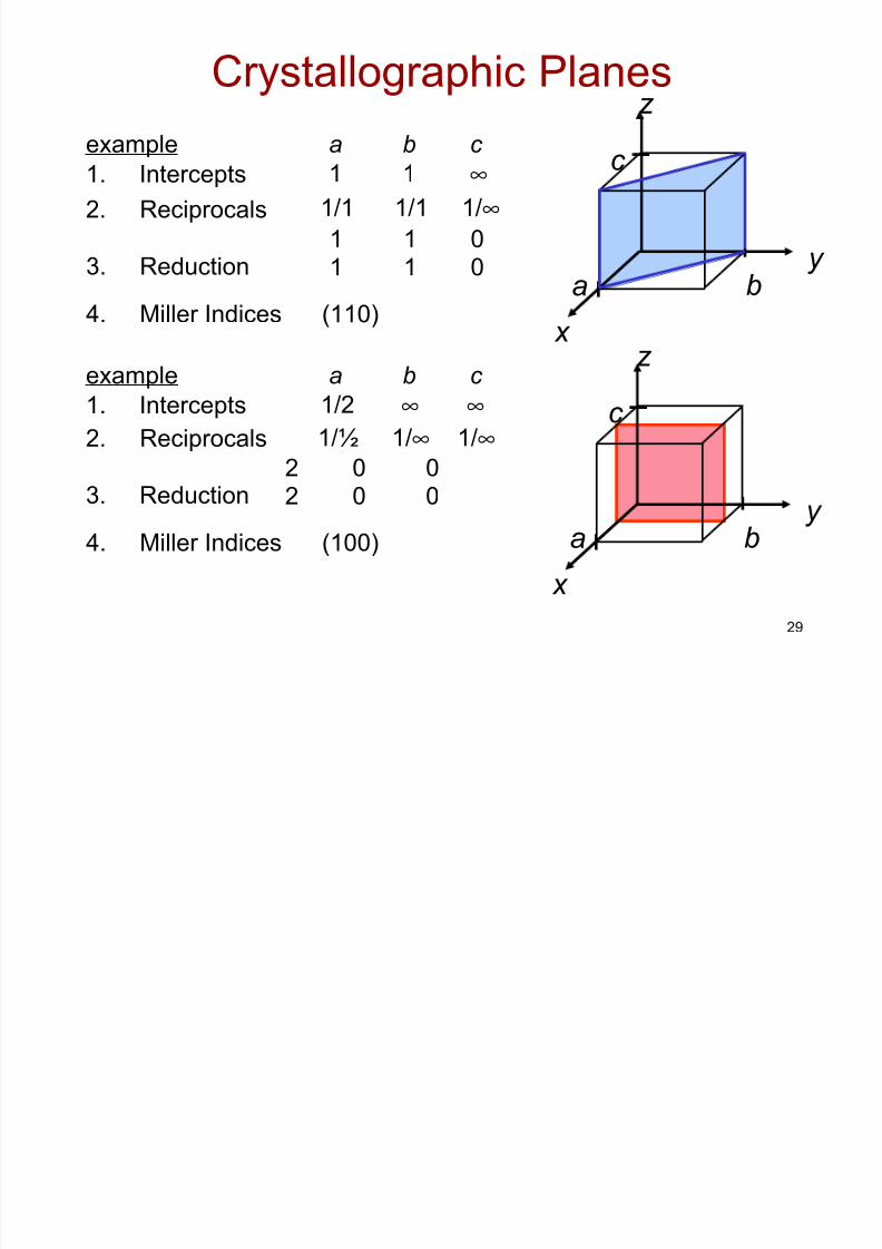
29
Crystallographic Planesz
x
y a b
c
4. Miller Indices (110)
example a b c z
x
y a b
c
4. Miller Indices (100)
1. Intercepts 1 1 ∞2. Reciprocals 1/1 1/1 1/∞
1 1 03. Reduction 1 1 0
1. Intercepts 1/2 ∞ ∞2. Reciprocals 1/½ 1/∞ 1/∞
2 0 03. Reduction 2 0 0
example a b c
8/7/2019 Ch03_the Structure of Metals
http://slidepdf.com/reader/full/ch03the-structure-of-metals 30/40
30
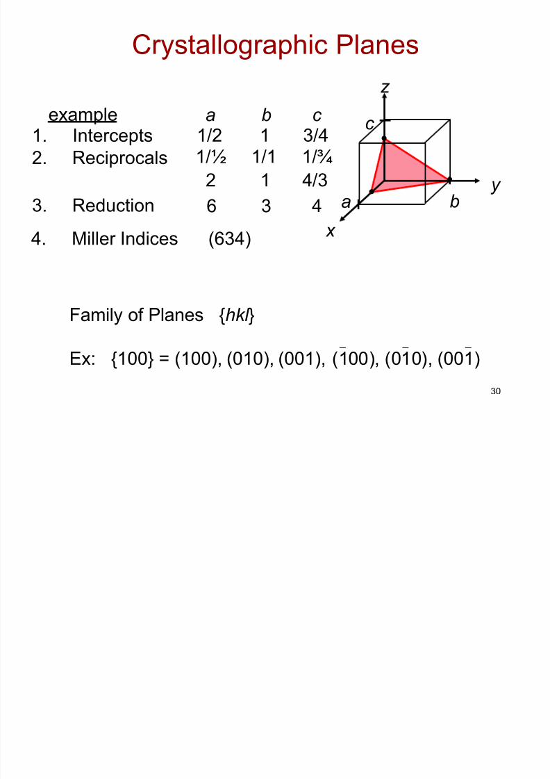
Crystallographic Planes
z
x
y a b
c •
•
•
4. Miller Indices (634)
example1. Intercepts 1/2 1 3/4
a b c
2. Reciprocals 1/½ 1/1 1/¾
2 1 4/3
3. Reduction 6 3 4
(001)(010),
Family of Planes {hkl }
(100), (010),(001),Ex: {100} = (100),
8/7/2019 Ch03_the Structure of Metals
http://slidepdf.com/reader/full/ch03the-structure-of-metals 31/40
31
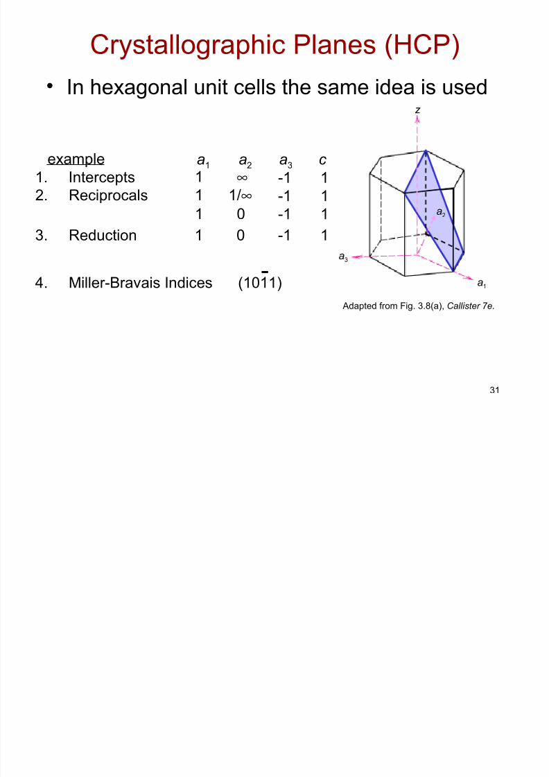
Crystallographic Planes (HCP)
• In hexagonal unit cells the same idea is used
example a1 a2 a3 c
4. Miller-Bravais Indices (1011)
1. Intercepts 1 ∞ -1 1
2. Reciprocals 1 1/∞1 0
-1-1
11
3. Reduction 1 0 -1 1
a2
a3
a1
z
Adapted from Fig. 3.8(a), Callister 7e.
8/7/2019 Ch03_the Structure of Metals
http://slidepdf.com/reader/full/ch03the-structure-of-metals 32/40
32
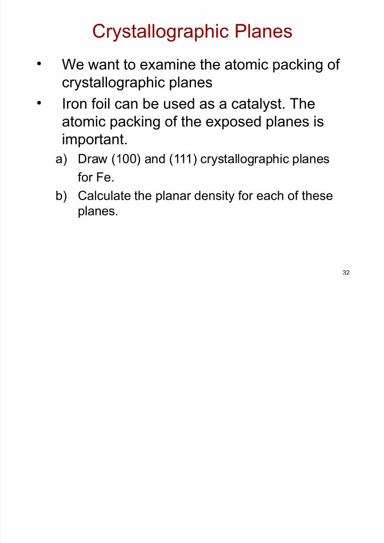
Crystallographic Planes
• We want to examine the atomic packing of crystallographic planes
• Iron foil can be used as a catalyst. The
atomic packing of the exposed planes is
important.a) Draw (100) and (111) crystallographic planes
for Fe.
b) Calculate the planar density for each of these
planes.
8/7/2019 Ch03_the Structure of Metals
http://slidepdf.com/reader/full/ch03the-structure-of-metals 33/40
33
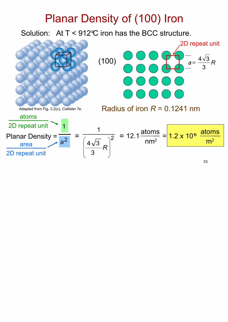
Planar Density of (100) Iron
Solution: At T < 912°C iron has the BCC structure.
(100)
Radius of iron R = 0.1241 nm
R 3
34a=
Adapted from Fig. 3.2(c), Callister 7e.
2D repeat unit
=Planar Density = a2
1
atoms
2D repeat unit
=nm2
atoms12.1
m2
atoms= 1.2 x 10¹⁹
1
2
R 3
34area
2D repeat unit
8/7/2019 Ch03_the Structure of Metals
http://slidepdf.com/reader/full/ch03the-structure-of-metals 34/40
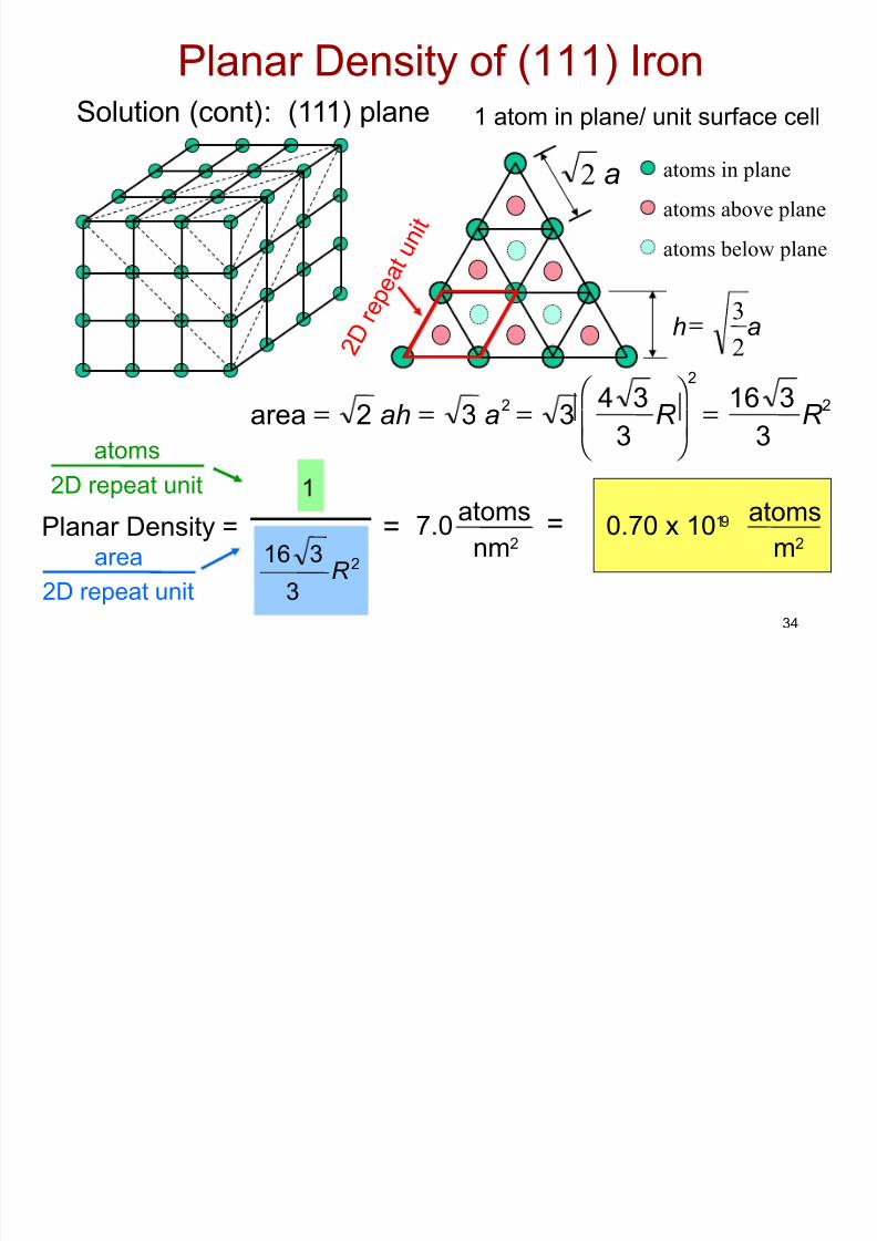
34
Planar Density of (111) IronSolution (cont): (111) plane 1 atom in plane/ unit surface cell
333
2
2
R 3
16R
3
4
2a3ah2area =
===
atoms in plane
atoms above plane
atoms below plane
ah23=
a2
2 D
r e p e a t u n i t
1
= =nm2
atoms7.0
m2
atoms0.70 x 1019
3 2R 3
16Planar Density =
atoms
2D repeat unit
area
2D repeat unit
8/7/2019 Ch03_the Structure of Metals
http://slidepdf.com/reader/full/ch03the-structure-of-metals 35/40
35
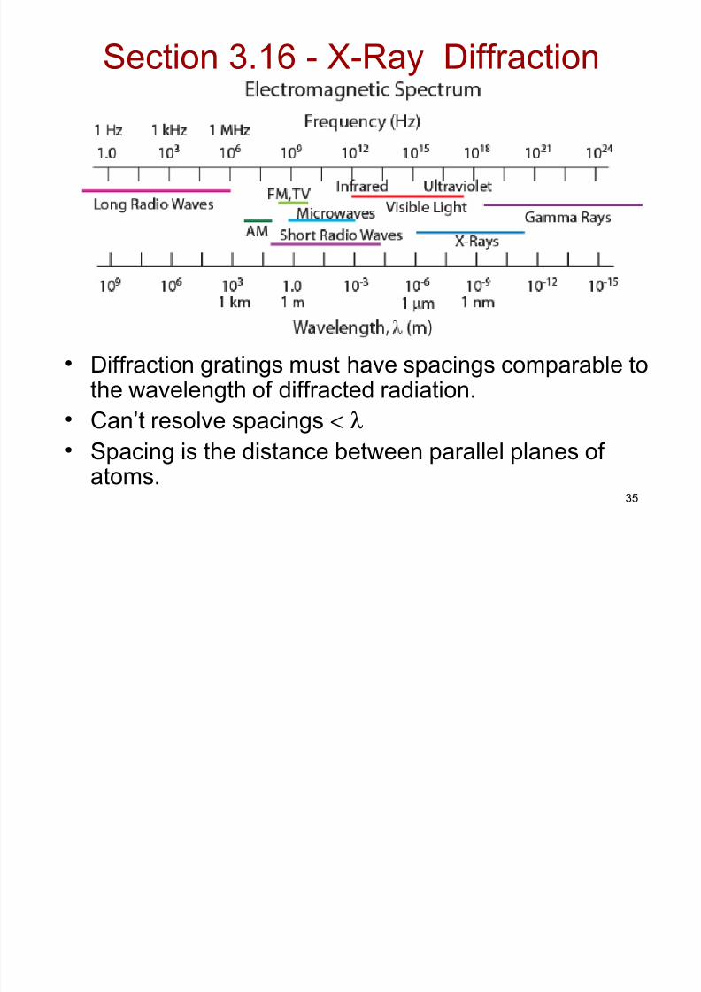
Section 3.16 - X-Ray Diffraction
• Diffraction gratings must have spacings comparable tothe wavelength of diffracted radiation.
• Can’t resolve spacings < λ• Spacing is the distance between parallel planes of
atoms.
8/7/2019 Ch03_the Structure of Metals
http://slidepdf.com/reader/full/ch03the-structure-of-metals 36/40
36
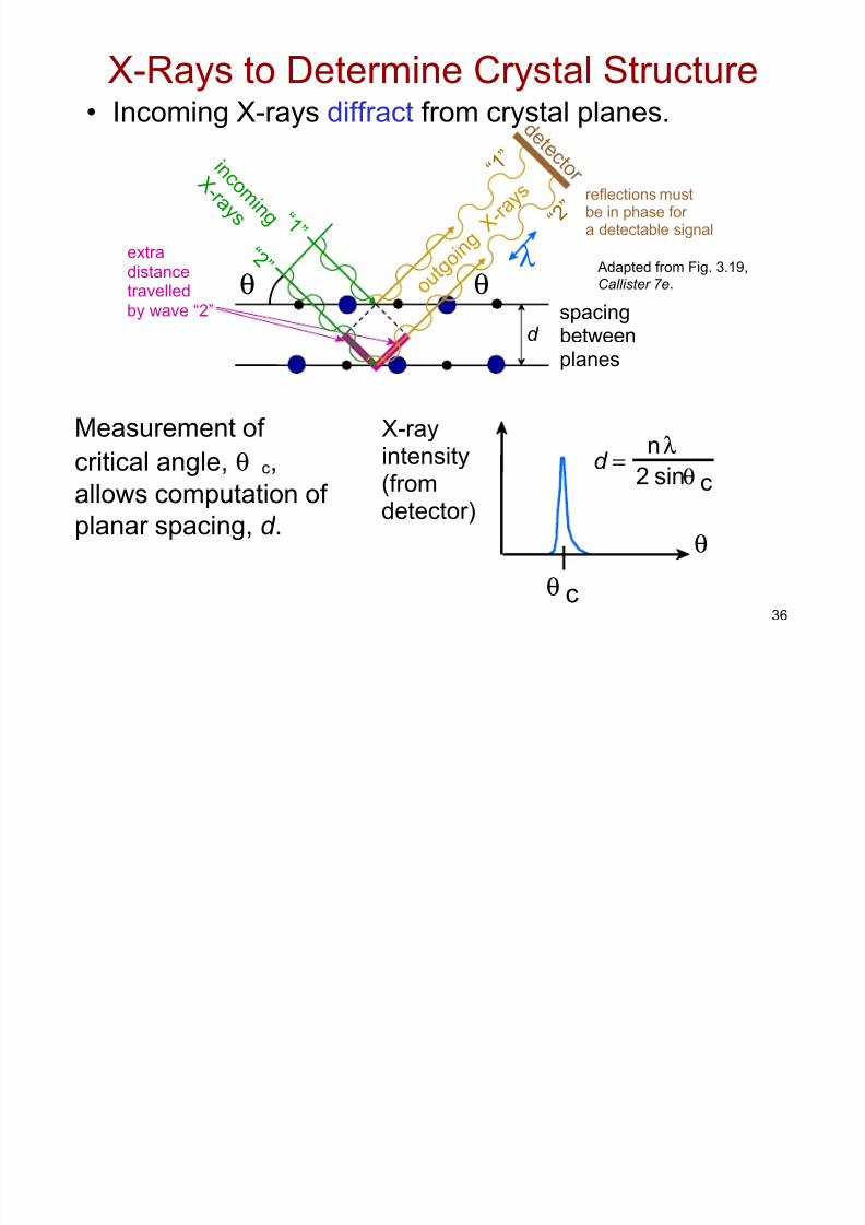
X-Rays to Determine Crystal Structure
X-ray
intensity(fromdetector)
θ
θ c
d =n
λ2 sinθ c
Measurement of
critical angle, θ c,allows computation of
planar spacing, d .
• Incoming X-rays diffract from crystal planes.
Adapted from Fig. 3.19,
Callister 7e.
reflections mustbe in phase for a detectable signal
spacingbetweenplanes
d
i n c o m i n g
X - r a y s
o u t g o i n g
X - r a
y s
d e
t e c t o r
θλ
θextradistancetravelled
by wave “2”
“ 1 ” “ 2 ”
“ 1 ”
“ 2 ”
8/7/2019 Ch03_the Structure of Metals
http://slidepdf.com/reader/full/ch03the-structure-of-metals 37/40
37
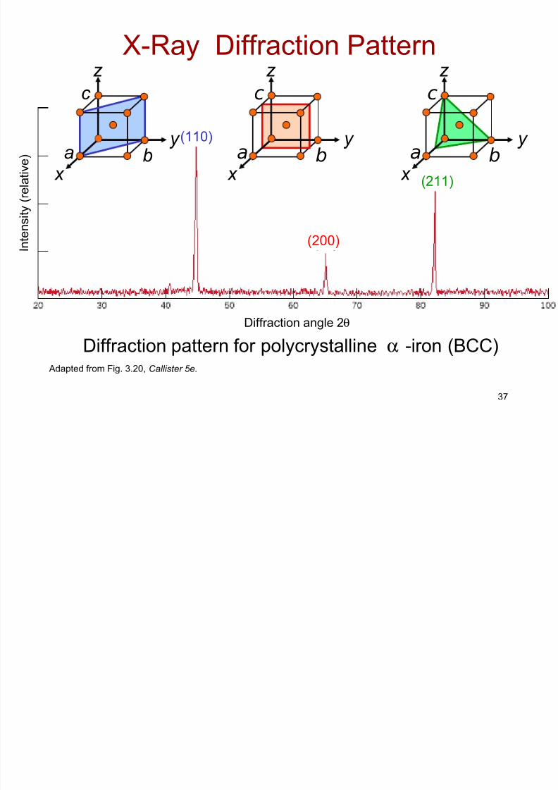
X-Ray Diffraction Pattern
Adapted from Fig. 3.20, Callister 5e.
(110)
(200)
(211)
z
x
y a b
c
Diffraction angle 2θ
Diffraction pattern for polycrystalline α -iron (BCC)
Intensity (
relative)
z
x
y a b
c
z
x
y a b
c
8/7/2019 Ch03_the Structure of Metals
http://slidepdf.com/reader/full/ch03the-structure-of-metals 38/40
38
• Atoms may assemble into crystalline or amorphous structures.
• We can predict the density of a material, provided we
know the atomic weight, atomic radius, and crystal
geometry (e.g., FCC, BCC, HCP).
SUMMARY
• Common metallic crystal structures are FCC, BCC, and
HCP. Coordination number and atomic packing factor
are the same for both FCC and HCP crystal structures.
• Crystallographic points, directions and planes are
specified in terms of indexing schemes.
Crystallographic directions and planes are related
to atomic linear densities and planar densities.
8/7/2019 Ch03_the Structure of Metals
http://slidepdf.com/reader/full/ch03the-structure-of-metals 39/40
39
• Some materials can have more than one crystal
structure. This is referred to as polymorphism (or
allotropy).
SUMMARY
• Materials can be single crystals or polycrystalline.Material properties generally vary with single crystal
orientation (i.e., they are anisotropic), but are generally
non-directional (i.e., they are isotropic) in polycrystals
with randomly oriented grains.
• X-ray diffraction is used for crystal structure andinterplanar spacing determinations.

8/7/2019 Ch03_the Structure of Metals
http://slidepdf.com/reader/full/ch03the-structure-of-metals 40/40
40
Core Problems:
Self-help Problems:
ANNOUNCEMENTS
Reading: