Embed Size (px)
Citation preview
Ch 28-DC Circuits

EMF & Terminal Voltage
9.0 V 8.7 V 8.7 V
V =ε − Ir
Terminal Open circuit internal!voltage voltage (emf) resistance

Resistors in series
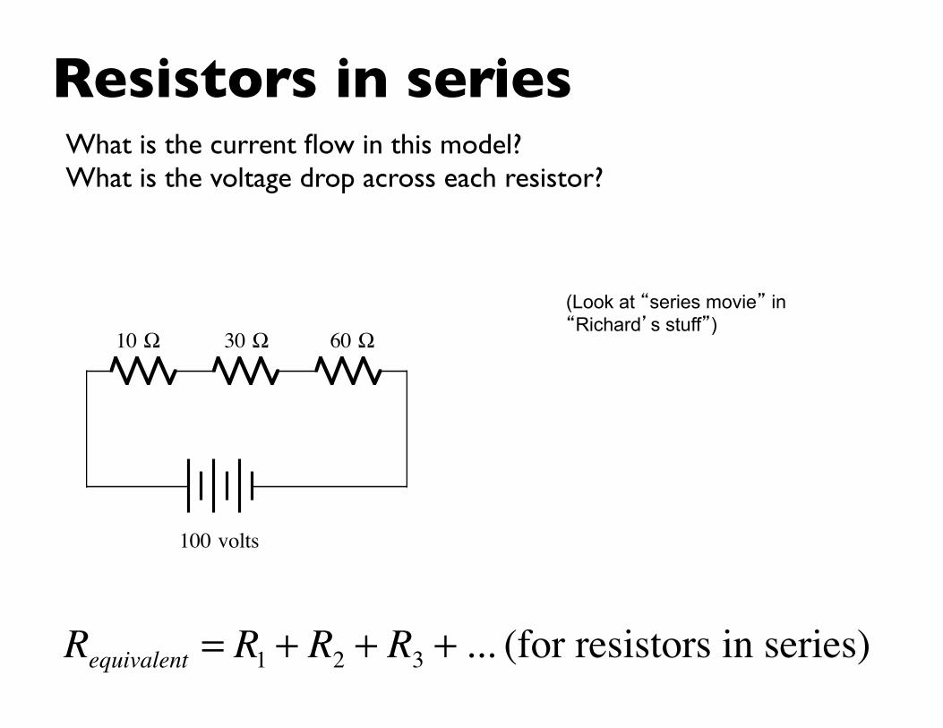
Resistors in seriesWhat is the current flow in this model?What is the voltage drop across each resistor?
Requivalent = R1 + R2 + R3 + ... (for resistors in series)
10 Ω 30 Ω 60 Ω
100 volts
(Look at “series movie” in “Richard’s stuff”)
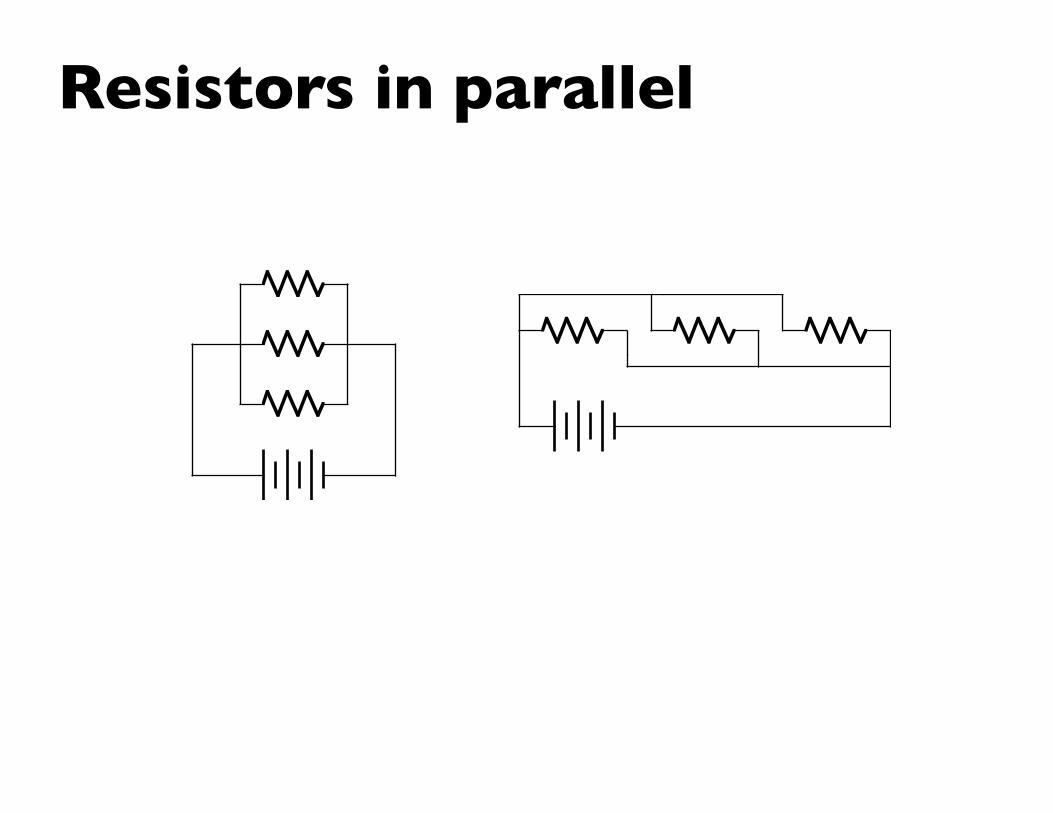
Resistors in parallel
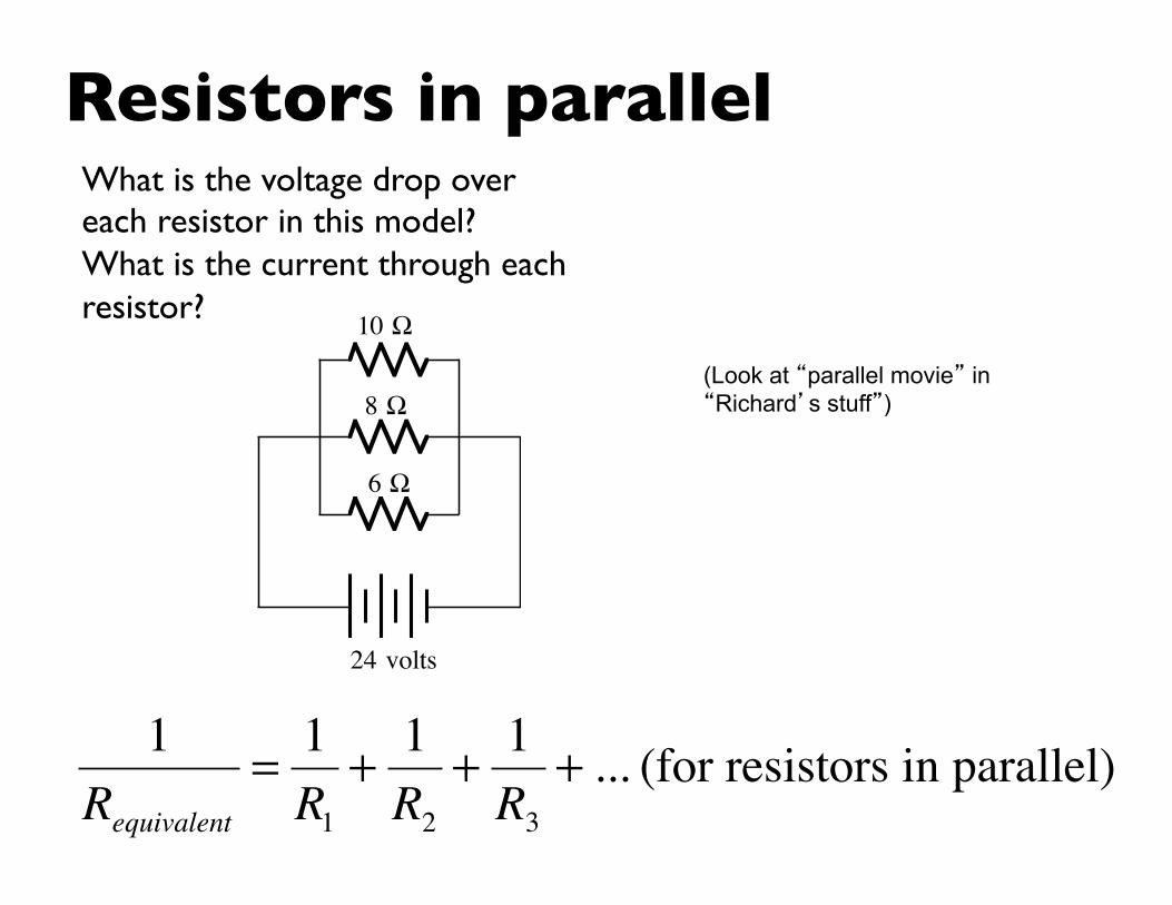
Resistors in parallelWhat is the voltage drop over each resistor in this model?What is the current through each resistor?
1Requivalent
= 1R1
+ 1R2
+ 1R3
+ ... (for resistors in parallel)
10 Ω
24 volts
8 Ω
6 Ω
(Look at “parallel movie” in “Richard’s stuff”)
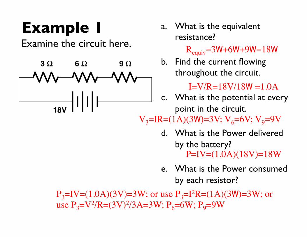
Example 1Examine the circuit here.
a. What is the equivalent resistance?
b. Find the current flowing throughout the circuit.
c. What is the potential at every point in the circuit.
d. What is the Power delivered by the battery?
e. What is the Power consumed by each resistor?
18V
3 Ω 6 Ω 9 Ω
Requiv=3W+6W+9W=18W
I=V/R=18V/18W =1.0A
V3=IR=(1A)(3W)=3V; V6=6V; V9=9V
P=IV=(1.0A)(18V)=18W
P3=IV=(1.0A)(3V)=3W; or use P3=I2R=(1A)(3W)=3W; or use P3=V2/R=(3V)2/3A=3W; P6=6W; P9=9W

Example 2Examine the circuit here.
a. What is the equivalent resistance?
b. Find the current flowing throughout the circuit.
c. What is the potential at every point in the circuit.
d. What is the Power delivered by the battery?
e. What is the Power consumed by each resistor?
24V
4Ω
6Ω
12Ω
1/Requiv=1/4W+1/6W+1/12W; Requiv=2W
V drop identical for each resistor=24V
I from battery = V/Requiv= 24V/2W =12A; I4=V/R=(24V)/(4W)=6A; I6=4A; I12=2A

Example 3Examine the circuit here.
a. What is the equivalent resistance?
b. Find the current flowing throughout the circuit.
c. What is the potential at every point in the circuit.
d. What is the Power delivered by the battery?
e. What is the Power consumed by each resistor?
36V
8 Ω
12 Ω
6 Ω

Kirchhoff’s Rules
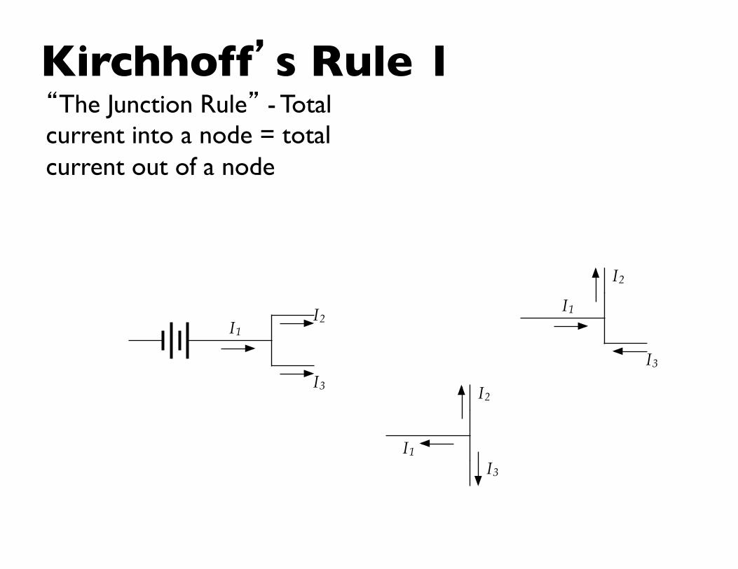
Kirchhoff’s Rule 1
I1 I2
I3
I1 I2
I3
I1
I2
I3
“The Junction Rule” - Total current into a node = total current out of a node
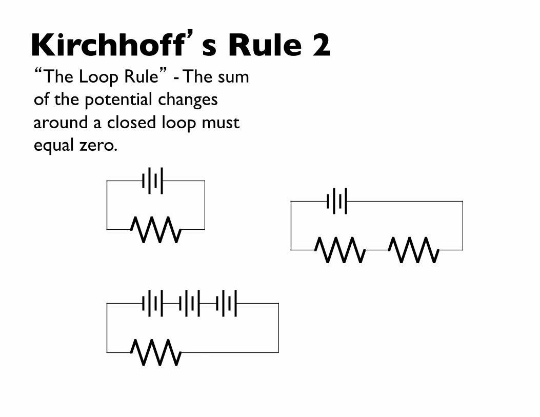
Kirchhoff’s Rule 2“The Loop Rule” - The sum of the potential changes around a closed loop must equal zero.
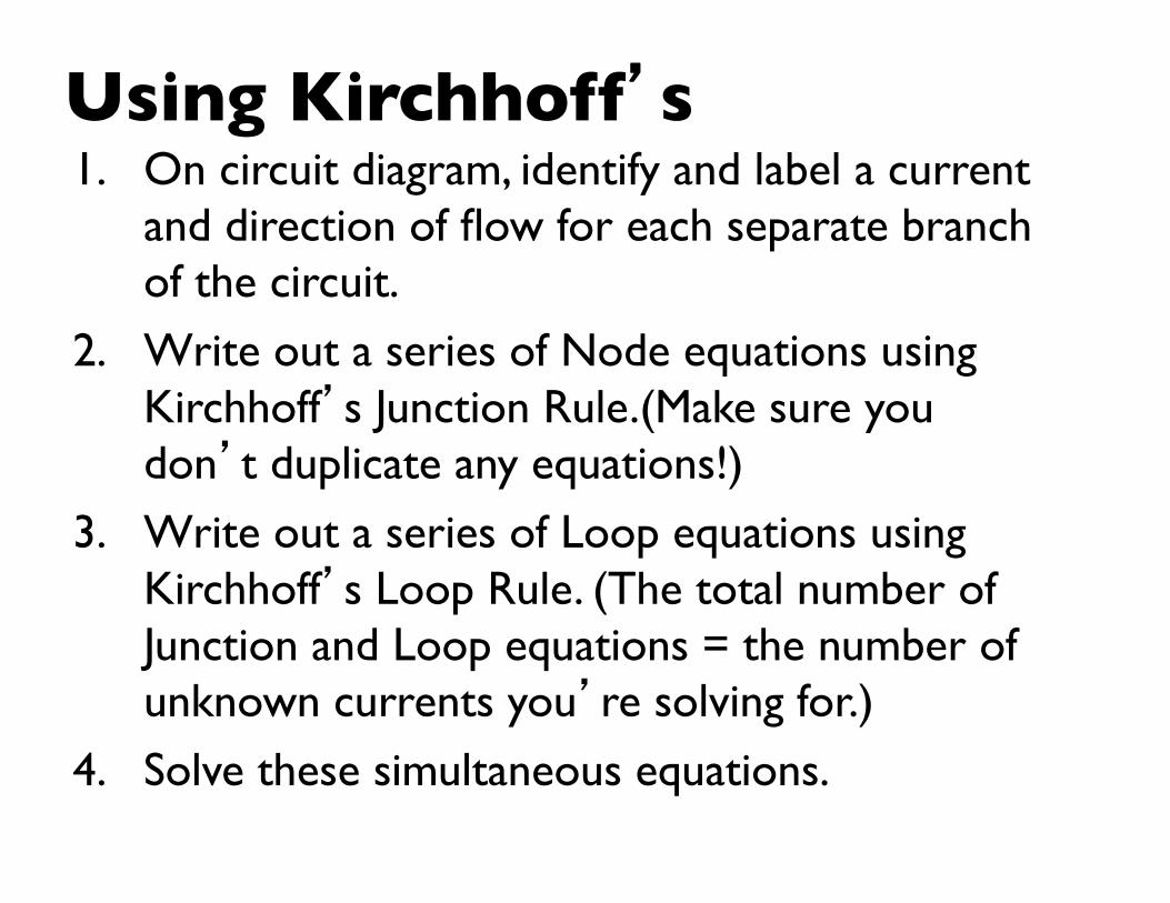
Using Kirchhoff’s1. On circuit diagram, identify and label a current
and direction of flow for each separate branch of the circuit.
2. Write out a series of Node equations using Kirchhoff’s Junction Rule.(Make sure you don’t duplicate any equations!)
3. Write out a series of Loop equations using Kirchhoff’s Loop Rule. (The total number of Junction and Loop equations = the number of unknown currents you’re solving for.)
4. Solve these simultaneous equations.
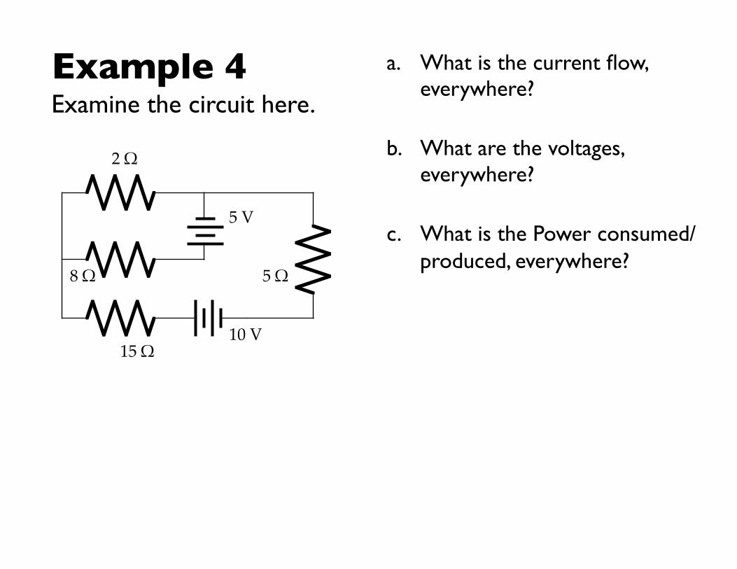
Example 4Examine the circuit here.
a. What is the current flow, everywhere?
b. What are the voltages, everywhere?
c. What is the Power consumed/produced, everywhere?
2 Ω
8 Ω
15 Ω 10 V
5 V
5 Ω
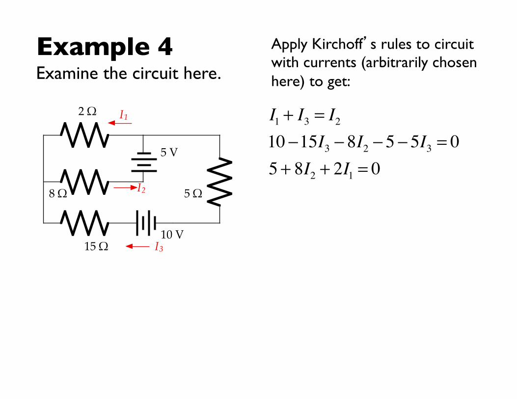
Example 4Examine the circuit here.
Apply Kirchoff’s rules to circuit with currents (arbitrarily chosen here) to get:
I2
2 Ω
8 Ω
15 Ω 10 V
5 V
5 Ω
I1
I3
I1 + I3 = I210 −15I3 − 8I2 − 5 − 5I3 = 05 + 8I2 + 2I1 = 0
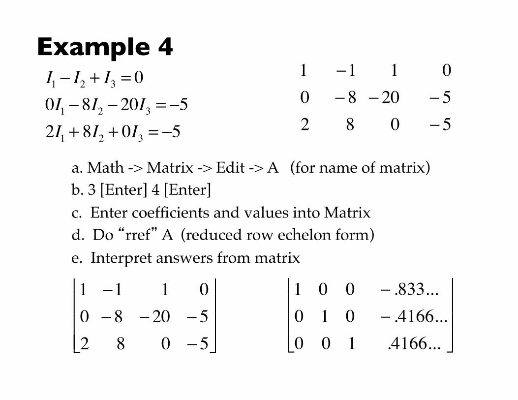
Example 4
I1 − I2 + I3 = 00I1 − 8I2 − 20I3 = −52I1 + 8I2 + 0I3 = −5
1 −1 1 00 − 8 − 20 − 52 8 0 − 5
a. Math -> Matrix -> Edit -> A (for name of matrix)b. 3 [Enter] 4 [Enter]c. Enter coefficients and values into Matrixd. Do “rref” A (reduced row echelon form)e. Interpret answers from matrix
1 −1 1 00 − 8 − 20 − 52 8 0 − 5
⎡
⎣
⎢ ⎢ ⎢
⎤
⎦
⎥ ⎥ ⎥
1 0 0 − .833...0 1 0 − .4166...0 0 1 .4166...
⎡
⎣
⎢ ⎢ ⎢
⎤
⎦
⎥ ⎥ ⎥

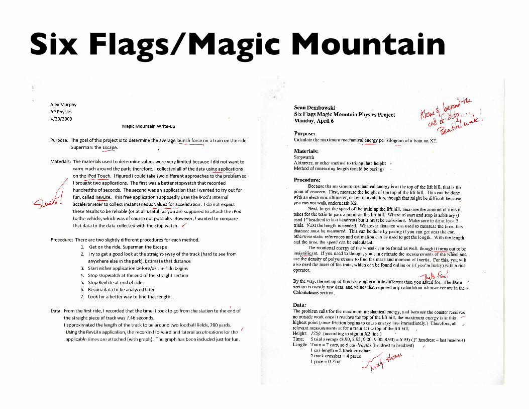
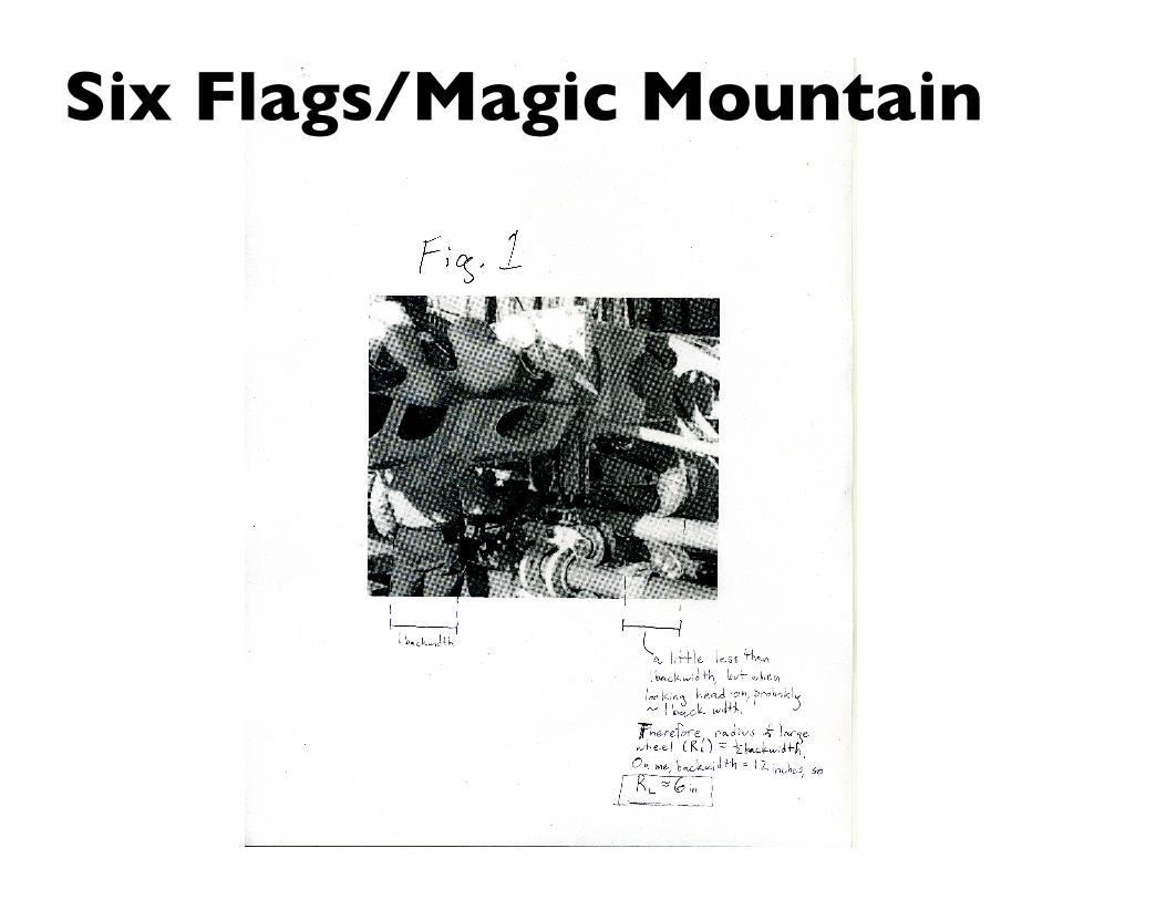
Six Flags/Magic MountainWhen: Monday, May 26, 2012Who: All able-bodied senior physics studentsHow much: Don't worry about it. (Book bill)
Leaving: In AM. Come to school and meet in 203.Returning: That depends. Let's talk about it.Assignment: One "applied physics" problem, assigned at beginning of AprilWrite-up: A "nice" one, word processed, 3-7 pages, with diagrams, illustrations, data tables, graphs, calculations, blurbs, explanations, sources of error, as required.
Six Flags/Magic Mountain

Six Flags/Magic Mountain
Six Flags/Magic Mountain
Series & Parallel ActivityExamine the series and parallel circuits assembled in class... and don’t touch the wires.
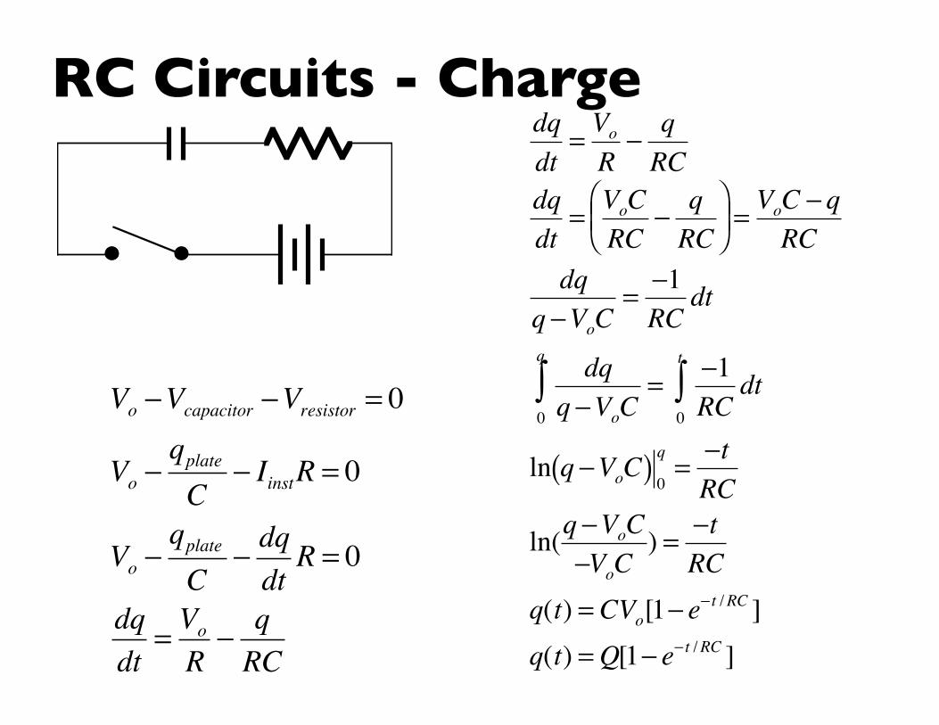
RC Circuits - Charge
Vo −Vcapacitor −Vresistor = 0
Vo −qplateC
− IinstR = 0
Vo −qplateC
− dqdtR = 0
dqdt
= Vo
R− qRC
dqdt
= Vo
R− qRC
dqdt
= VoCRC
− qRC
⎛ ⎝ ⎜
⎞ ⎠ ⎟ = VoC − q
RCdq
q −VoC= −1RC
dt
dqq −VoC0
q
∫ = −1RC
dt0
t
∫
ln q −VoC( ) 0q
= −tRC
ln(q −VoC−VoC
) = −tRC
q(t) = CVo[1− e− t /RC ]
q(t) = Q[1− e− t /RC ]
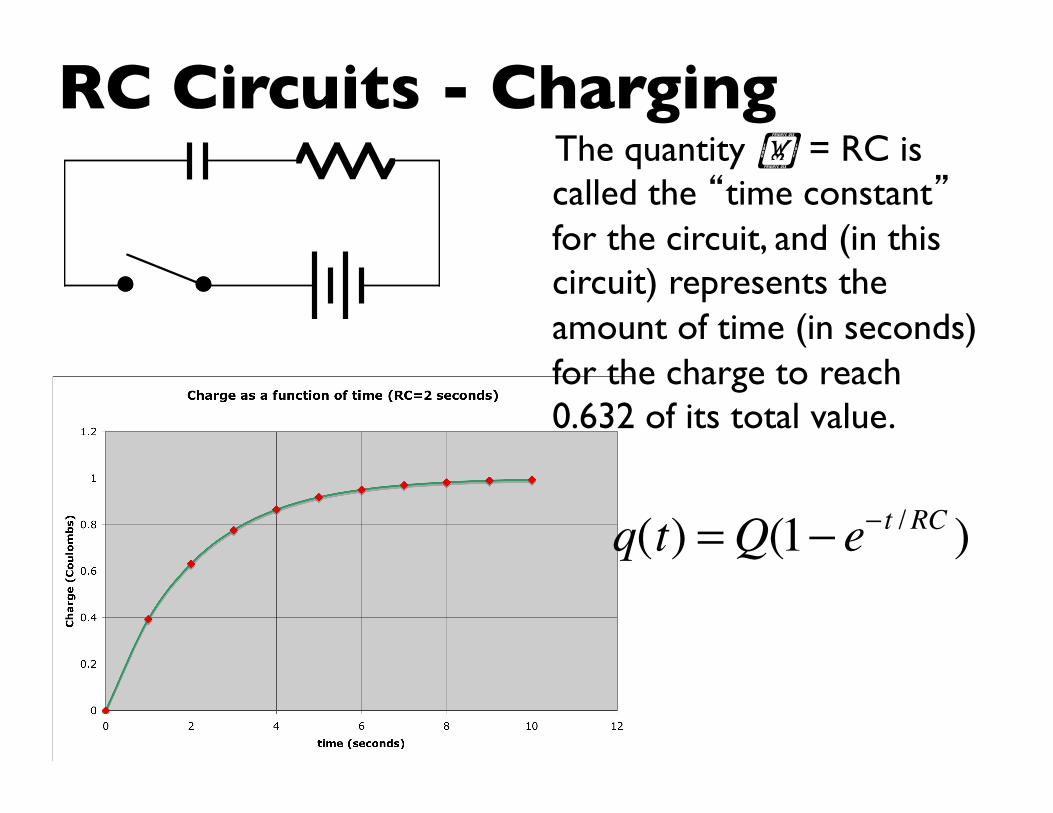
RC Circuits - ChargingThe quantity = RC is called the “time constant” for the circuit, and (in this circuit) represents the amount of time (in seconds) for the charge to reach 0.632 of its total value.
q(t) = Q(1− e− t /RC )
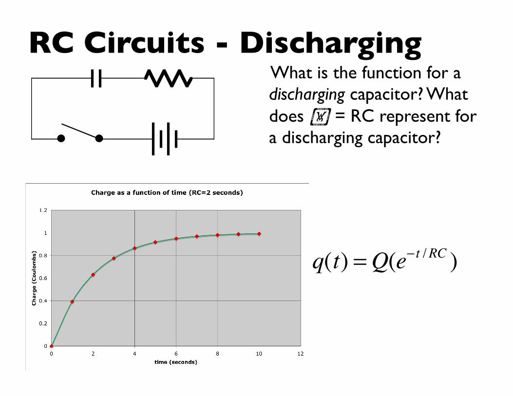
RC Circuits - DischargingWhat is the function for a discharging capacitor? What does = RC represent for a discharging capacitor?
q(t) = Q(e− t /RC )
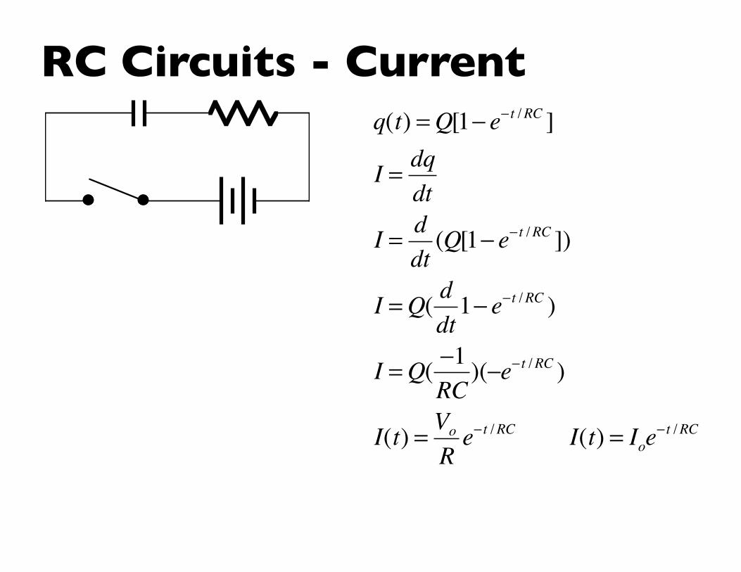
RC Circuits - Current
q(t) = Q[1− e− t /RC ]
I = dqdt
I = ddt
(Q[1− e− t /RC ])
I = Q( ddt
1− e−t /RC )
I = Q( −1RC
)(−e− t /RC )
I(t) = Vo
Re− t /RC I(t) = Ioe
− t /RC

RC Circuits - CurrentWhat is the function for current of a discharging capacitor?
I(t) = − QRC
e−t /RC

Example 5An RC circuit has a 6V battery, a 200µF capacitor, and a 5000 resistor.
a. Draw a picture of the circuit.b. What is the flow of current
through the circuit Io just after the switch is thrown?
c. What is the time constant for the circuit?
d. How much current is flowing in the circuit 5 seconds after the switch has been thrown?
e. Sketch a graph of the circuit’s current vs. time, using at least 3 data points that you calculate.

GalvanometersA galvanometer is a type of meter that, in conjunction with appropriate resistors, will allow one to measure current (as an ammeter) and electric potential difference (as a voltmeter).
Ideal ammeters have low resistance.
Ideal voltmeters have high resistance.
COM VΩ
COM VΩ
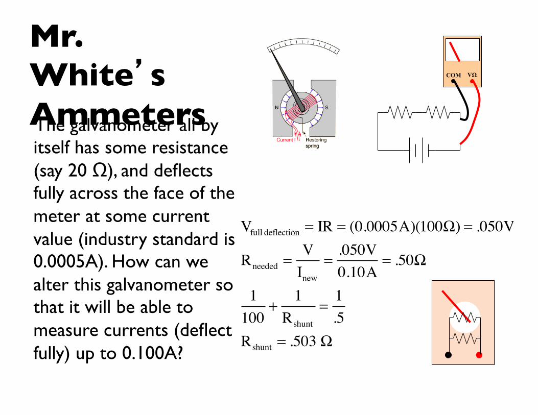
Mr. White’s AmmetersThe galvanometer all by itself has some resistance (say 20 Ω), and deflects fully across the face of the meter at some current value (industry standard is 0.0005A). How can we alter this galvanometer so that it will be able to measure currents (deflect fully) up to 0.100A?
COM VΩ
Vfull deflection = IR = (0.0005A)(100Ω) = .050V
Rneeded =V
Inew
=.050V0.10A
= .50Ω
1100
+1
Rshunt
=1.5
Rshunt = .503 Ω

VoltmetersThe galvanometer all by itself has some resistance (say 100Ω), and deflects fully across the face of the meter at some potential value (say 0.10V). How can we alter this galvanometer so that it will be able to measure currents (deflect fully) up to 10V?
V = IR = (0.001A)(100Ω) = 0.10V
Rneeded = Vnew
I= 10V0.001A
=10,000Ω
100 + R =10,000ΩR = 9900Ω
COM VΩ