Embed Size (px)
Citation preview
CGT Ultra-high PurityNitrogen Generators
www.nitrogen-generators.com
High Purity Nitrogen
Compressed Gas Technologies Inc. has been an industry leader of on-site nitrogen generators throughout North America since 2001. We can help you save money on your nitrogen gas costs.
Our line of generators allows you to produce nitrogen gas on-site, simply and cost effectively from a supply of compressed air. Eliminate rental charges, transportation expenses, labor costs, and evaporation losses of bulk systems.
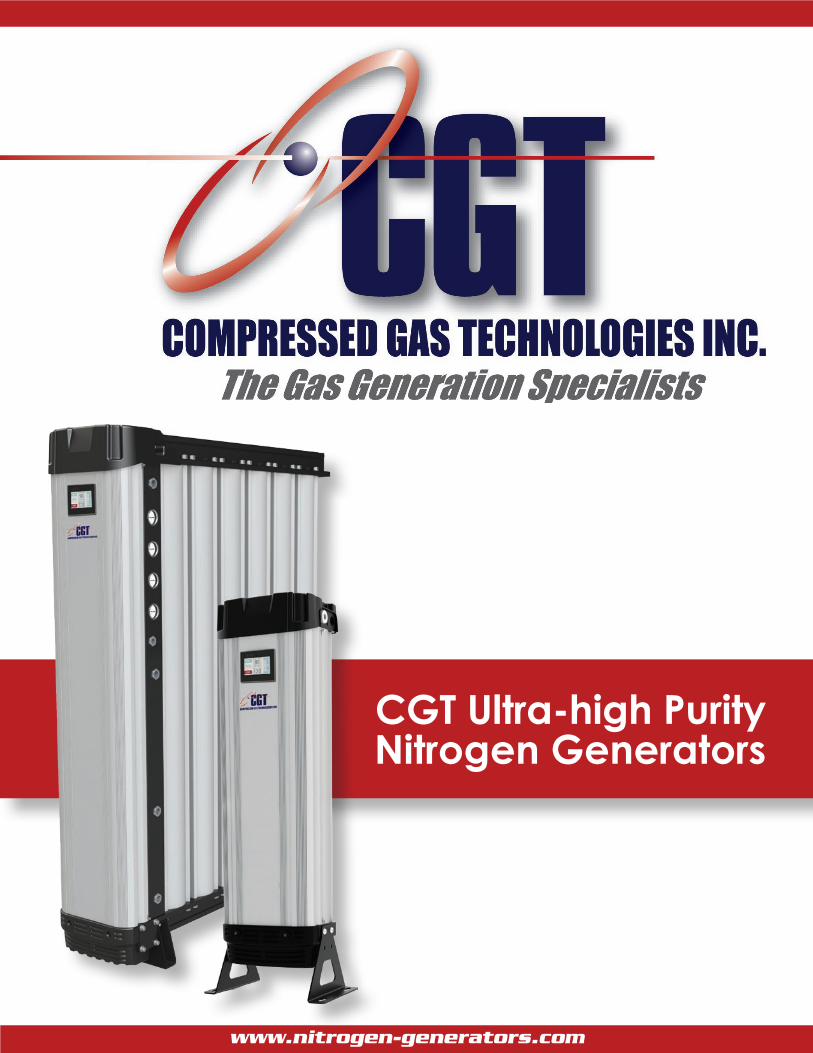
Design Research & Development Manufacture
Our experienced team of design engineers are always looking for new and unique technologies and products to bring you the highest level of performance and lowest overall operating cost.
Our team endeavors to provide solutions that go beyond developing an existing product. They are continually researching new technologies which can provide unique advantages over competitive offerings.
These advanced, reliable and energy saving Nitrogen generators are manufactured in a state of the art facility to the highest standards of build quality to ensure reliability and high levels of performance.
Nitrogen is used in many commercial and industrial applications to improve the quality of a product or process, or as a safety measure to prevent combustion. Liquid or bottled Nitrogen delivery and storage can be expensive, unreliable, and a safety concern. Nitrogen generators allow users to produce Nitrogen in-house simply and inexpensively using an existing compressed air system.
CGT recognizes the importance of having a safe, reliable and cost effective supply of high-purity Nitrogen. We bring you this Nitrogen generator to meet the increasing demand for high quality complete packaged solutions which save energy and time, while fulfilling the needs of their intended application.
CGT Ultra-high PurityNitrogen Generators
www.nitrogen-generators.com
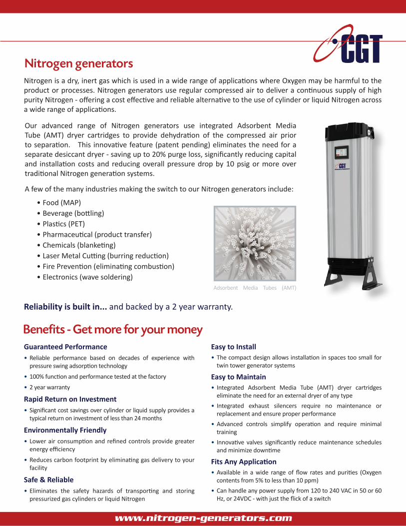
Nitrogen generators
Benefits - Get more for your money
Reliability is built in... and backed by a 2 year warranty.
Our advanced range of Nitrogen generators use integrated Adsorbent Media Tube (AMT) dryer cartridges to provide dehydration of the compressed air prior to separation. This innovative feature (patent pending) eliminates the need for a separate desiccant dryer - saving up to 20% purge loss, significantly reducing capital and installation costs and reducing overall pressure drop by 10 psig or more over traditional Nitrogen generation systems.
A few of the many industries making the switch to our Nitrogen generators include:
• Food (MAP)• Beverage (bottling)• Plastics (PET)• Pharmaceutical (product transfer)• Chemicals (blanketing)• Laser Metal Cutting (burring reduction)• Fire Prevention (eliminating combustion)• Electronics (wave soldering)
Nitrogen is a dry, inert gas which is used in a wide range of applications where Oxygen may be harmful to the product or processes. Nitrogen generators use regular compressed air to deliver a continuous supply of high purity Nitrogen - offering a cost effective and reliable alternative to the use of cylinder or liquid Nitrogen across a wide range of applications.
Guaranteed Performance• Reliable performance based on decades of experience with
pressure swing adsorption technology
• 100% function and performance tested at the factory
• 2 year warranty
Rapid Return on Investment• Significant cost savings over cylinder or liquid supply provides a
typical return on investment of less than 24 months
Environmentally Friendly• Lower air consumption and refined controls provide greater
energy efficiency
• Reduces carbon footprint by eliminating gas delivery to your facility
Safe & Reliable• Eliminates the safety hazards of transporting and storing
pressurized gas cylinders or liquid Nitrogen
Easy to Install• The compact design allows installation in spaces too small for
twin tower generator systems
Easy to Maintain• Integrated Adsorbent Media Tube (AMT) dryer cartridges
eliminate the need for an external dryer of any type• Integrated exhaust silencers require no maintenance or
replacement and ensure proper performance• Advanced controls simplify operation and require minimal
training• Innovative valves significantly reduce maintenance schedules
and minimize downtime
Fits Any Application• Available in a wide range of flow rates and purities (Oxygen
contents from 5% to less than 10 ppm)• Can handle any power supply from 120 to 240 VAC in 50 or 60
Hz, or 24VDC - with just the flick of a switch
Adsorbent Media Tubes (AMT)
www.nitrogen-generators.com
Integrated AMT dryer cartridgeTraditional Nitrogen generators often require installing and operating an external desiccant dryer. Our innovative Nitrogen generators feature an integrated Adsorbent Media Tube (AMT) dryer cartridge which eliminates the need for a pre-treatment dryer of any type. The integrated drying system reduces purge loss by approximately 20% and reduces pressure drop by 10 psi or more, providing significant energy savings over a traditional generator system.
Ecomode energy saving controlThis unique control feature utilizes an outlet pressure monitor to reduce energy consumption during periods of low demand to ensure a continuous uninterrupted Nitrogen supply while minimizing power consumption.
PLC controlled operationEach CGT Nitrogen generator is operated by a reliable PLC control system with digital and analog outputs for remote monitoring and alarm capabilities. Includes an easy-to-operate touch screen graphical interface which offers valuable features including ‘power on’, ‘hours run’, ‘Oxygen purity’, ‘pressure’, ‘online column’ and ‘service required’ indicators. In addition, four pressure gauges provide the operator with continuous indication of column A, column B, air inlet and Nitrogen outlet pressures.
Multi-bank designThe unique multi-bank design (GEN2 2110 to GEN2 12130) enables additional generators to be added in the future as demand increases. Your CGT Nitrogen generator can grow with your company.
Reliable high performance valvesInlet, outlet and exhaust are managed through coaxial flow valves integrated into the upper and lower manifolds. These low maintenance valves provide unrestricted flow capacity. They are designed for durability, ease of maintenance and long service life and are backed by a comprehensive two year warranty.
Maximum corrosion protection High tensile aluminum columns are first alocromed and then powder coated to provide maximum protection for corrosive environments.
Optional Oxygen analyzer A built in Oxygen Analyzer continuously monitors the Oxygen concentration in the Nitrogen stream. The analyzer is incorporated into the PLC controls to guarantee downstream purity levels are consistently achieved and maintained.
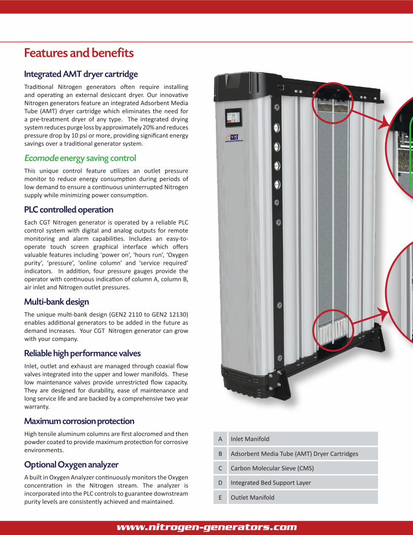
A Inlet Manifold
B Adsorbent Media Tube (AMT) Dryer Cartridges
C Carbon Molecular Sieve (CMS)
D Integrated Bed Support Layer
E Outlet Manifold
www.nitrogen-generators.com
Features and benefits
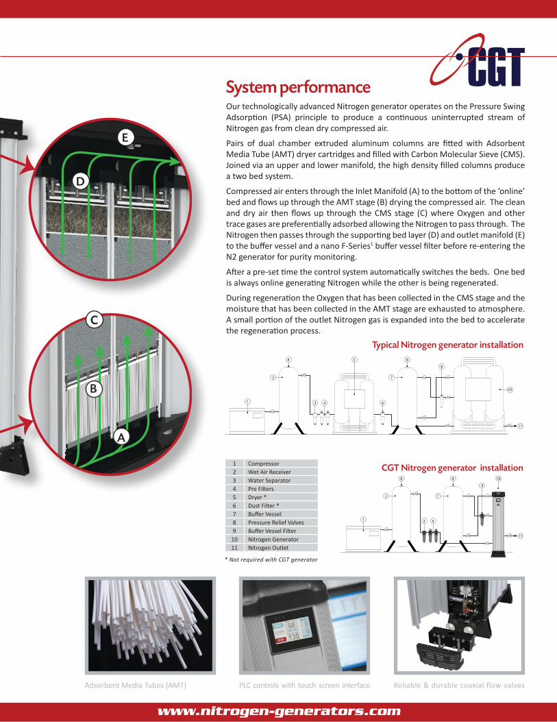
System performanceOur technologically advanced Nitrogen generator operates on the Pressure Swing Adsorption (PSA) principle to produce a continuous uninterrupted stream of Nitrogen gas from clean dry compressed air.
Pairs of dual chamber extruded aluminum columns are fitted with Adsorbent Media Tube (AMT) dryer cartridges and filled with Carbon Molecular Sieve (CMS). Joined via an upper and lower manifold, the high density filled columns produce a two bed system.
Compressed air enters through the Inlet Manifold (A) to the bottom of the ‘online’ bed and flows up through the AMT stage (B) drying the compressed air. The clean and dry air then flows up through the CMS stage (C) where Oxygen and other trace gases are preferentially adsorbed allowing the Nitrogen to pass through. The Nitrogen then passes through the supporting bed layer (D) and outlet manifold (E) to the buffer vessel and a nano F-Series1 buffer vessel filter before re-entering the N2 generator for purity monitoring.
After a pre-set time the control system automatically switches the beds. One bed is always online generating Nitrogen while the other is being regenerated.
During regeneration the Oxygen that has been collected in the CMS stage and the moisture that has been collected in the AMT stage are exhausted to atmosphere. A small portion of the outlet Nitrogen gas is expanded into the bed to accelerate the regeneration process.
11
9
88
7
1 3 4
2
PURIFICATION SOLUTIONS PURIFICATION SOLUTIONSPURIFICATION SOLUTIONS
11
9
88
1 3 4
2
5
PURIFICATION SOLUTIONS
7
10
10
6
Typical Nitrogen generator installation
1 Compressor2 Wet Air Receiver3 Water Separator4 Pre Filters5 Dryer *6 Dust Filter *7 Buffer Vessel8 Pressure Relief Valves9 Buffer Vessel Filter
10 Nitrogen Generator11 Nitrogen Outlet
* Not required with CGT generator
CGT Nitrogen generator installation
11
9
88
7
1 3 4
2
PURIFICATION SOLUTIONS PURIFICATION SOLUTIONSPURIFICATION SOLUTIONS
11
9
88
1 3 4
2
5
PURIFICATION SOLUTIONS
7
10
10
6
PLC controls with touch screen interface Reliable & durable coaxial flow valvesAdsorbent Media Tubes (AMT)
E
D
C
B
A
www.nitrogen-generators.com

Technical data
ModelOutlet Flow
(1)
Nitrogen Purity at the Outlet (Maximum Oxygen Content) Dimensionsin (mm) Weight
lbs (kg)99.999% 99.995% 99.99% 99.75% 99.95% 99.9% 99.5% 99% 98% 97% 96% 95%(10 ppm) (50 ppm) (100 ppm) (250 ppm) (500 ppm) (0.10%) (0.50%) (1%) (2%) (3%) (4%) (5%) A B C
GEN2 1110scfh 49 71 81 95 110 127 184 205 258 293 336 364 48
(1220)16
(400)23
(580)176(50)m3/hr 1.4 2.0 2.3 2.7 3.1 3.6 5.2 5.8 7.3 8.3 9.5 10.3
GEN2 2110scfh 99 141 162 191 219 254 367 410 516 586 671 728 48
(1220)16
(400)30
(760)242
(110)m3/hr 2.8 4.0 4.6 5.4 6.2 7.2 10.4 11.6 14.6 16.6 19.0 20.6
GEN2 3110scfh 148 212 244 286 328 381 551 615 773 879 1007 1091 48
(1220)16
(400)36
(910)374
(170)m3/hr 4.2 6.0 6.9 8.1 9.3 10.8 15.6 17.4 21.9 24.9 28.5 30.9
GEN2 2130scfh 180 254 297 353 403 466 667 742 932 1070 1218 1324 71
(1800)16
(400)30
(760)365
(166)m3/hr 5.1 7.2 8.4 10.0 11.4 13.2 18.9 21.0 26.4 30.3 34.5 37.5
GEN2 3130scfh 270 381 445 529 604 699 1001 1112 1398 1605 1828 1986 71
(1800)16
(400)36
(910)490
(222)m3/hr 7.6 10.8 12.6 15.0 17.1 19.8 28.3 31.5 39.6 45.4 51.8 56.2
GEN2 4130scfh 360 509 593 706 805 932 1335 1483 1865 2140 2437 2649 71
(1800)16
(400)43
(1090)610
(277)m3/hr 10.2 14.4 16.8 20.0 22.8 26.4 37.8 42.0 52.8 60.6 69.0 75.0
GEN2 6130scfh 540 763 890 1058 1208 1398 2002 2225 2797 3210 3655 3973 71
(1800)16
(400)56
(1420)852
(387)m3/hr 15.3 21.6 25.2 30.0 34.2 39.6 56.7 63.0 79.2 90.9 103.5 112.5
GEN2 8130scfh 720 1017 1187 1411 1610 1865 2670 2966 3729 4280 4873 5297 71
(1800)16
(400)69
(1750)1100(550)m3/hr 20.4 28.8 33.6 40.0 45.6 52.8 75.6 84.0 105.6 121.2 138.0 150.0
GEN2 10130scfh 828 1170 1365 1623 1852 2144 3070 3411 4289 4922 5604 6092 71
(1800)16
(400)83
(2110)1350(610)m3/hr 23.4 33.1 38.7 46.0 52.4 60.7 86.9 96.6 121.4 139.4 158.7 172.5
GEN2 12130scfh 962 1358 1584 1884 2150 2489 3564 3960 4979 5714 6506 7072 71
(1800)16
(400)96
(2440)1600(722)m3/hr 27.2 38.5 44.9 53.3 60.9 70.5 100.9 112.1 141.0 161.8 184.2 200.3
Correction FactorsTo calculate the outlet flow for any model at operating conditions other than those above:
Outlet Flow (from table above) x K1 x K2 (from tables below) = Outlet Flow at new conditions (4)
Inlet Temperature - oF (oC) 50 - 75oF (10 - 24oC) 85oF (30oC) 95oF (35oC) 105oF (41oC)
K1
10 ppm 1 0.90 0.81 0.66
50 to 500 ppm 1 0.98 0.86 0.75
0.1 to 5.0% 1 0.98 0.95 0.90
Inlet Pressure - psig (barg) 90 (6) 100 (7) 115 (8) 130 (9) 145 (10) 160 (11) 174 - 232 (12 - 16)
K2 0.90 1.00 1.10 1.20 1.25 1.30 1.35
Inlet Air Purity Requirements Inlet Temperature Working Pressure Outlet Gas Dewpoint
SupplyVoltageParticulate Dewpoint Oil Content Minimum Maximum Minimum Maximum
< 0.1 micron < 80oF (27oC)PDP < 0.01 ppm (2) 50oF
(10oC)104oF(40oC)
87 psig(6 barg)
232 psig(16 barg)
< -40o F (-40oC)PDP (3)
120-240 VAC50 or 60 Hzor 24 VDC
(1) At 100 psig inlet pressure and 68 - 77oF inlet temperature. For outlet flow at all other conditions, refer to the correction factors above or contact us.(2) Including oil vapor.(3) Outlet gas dewpoint is < -76oF (-60oC) in high purity applications.(4) To be used as a rough guide only. All applications should be confirmed by CGT. Contact us for sizing assistance. A
B C
A
B C
GEN2 1110 to 12130
U.S. Mailing address:
Compressed Gas TechnologiesP.O. Box 1953 - Troy, Michigan, USA - 48099-1953
email: [email protected]: www.nitrogen-generators.com
Canadian Mailing address:
Compressed Gas TechnologiesP.O. Box 61, Station “A” - Windsor, Ontario, Canada - N9A 6J5
Toll Free: 1-877-737-7760Phone: 1-519-737-7760 - Fax: 1-519-737-6944