Embed Size (px)
Citation preview

en
s
CG60_CG60DL_TMA_0498_00_01_23225_A6L.fm Page -1 Tuesday, November 22, 2011 12:19 PM
Model CG60Model CG60DL
Corrosion Gauge
Operating Instruction

en
This product meets The product is ClasGroup 1 ISM produc used conductively coupled radio-frequency energy w nt itself.
Class A product are and those directly connected to alow voltage power s urposes.
is a
All other trademarks© Copyright ElcomeAll rights reserved. transcribed, stored (in a retrievalsystem or otherwise (electronic, mechanical, magnetic,optical, manual or ot ited.A copy of this Instru w.elcometer.com.
Doc.No. TMA-0498 Issue 01Text with Cover No: 23225
CG60_CG60DL_TMA_0498_00_01_23225_A6L.fm Page 0 Tuesday, November 22, 2011 12:19 PM
the Electromagnetic Compatibility Directive.s A, Group 1 ISM equipment according to CISPR 11.t: A product in which there is intentionally generated and/or
hich is necessary for the internal functioning of the equipme
suitable for use in all establishments other than domestic upply network which supplies buildings used for domestic p
registered trademark of Elcometer Limited.
acknowledged.ter Limited. 2011.No part of this document may be reproduced, transmitted,) or translated into any language, in any form or by any meansherwise) without the prior written permission of Elcometer Limction Manual is available for download on our Website via ww

1
en
. . . . . . . . . . . . . . . . . . . . . . . . . . . 2
. . . . . . . . . . . . . . . . . . . . . . . . . . . 4
. . . . . . . . . . . . . . . . . . . . . . . . . . . 8
. . . . . . . . . . . . . . . . . . . . . . . . . . 10
. . . . . . . . . . . . . . . . . . . . . . . . . . 13
. . . . . . . . . . . . . . . . . . . . . . . . . . 15
. . . . . . . . . . . . . . . . . . . . . . . . . . 21
. . . . . . . . . . . . . . . . . . . . . . . . . . 23
. . . . . . . . . . . . . . . . . . . . . . . . . . 28
. . . . . . . . . . . . . . . . . . . . . . . . . . 31
. . . . . . . . . . . . . . . . . . . . . . . . . . 33
. . . . . . . . . . . . . . . . . . . . . . . . . . 34
. . . . . . . . . . . . . . . . . . . . . . . . . . 34
. . . . . . . . . . . . . . . . . . . . . . . . . . 36
. . . . . . . . . . . . . . . . . . . . . . . . . . 38
. . . . . . . . . . . . . . . . . . . . . . . . . . 38
. . . . . . . . . . . . . . . . . . . . . . . . . . 43
. . . . . . . . . . . . . . . . . . . . . . . . . . 43
. . . . . . . . . . . . . . . . . . . . . . . . . . 46
CG60_CG60DL_TMA_0498_00_01_23225_A6L.fm Page 1 Tuesday, November 22, 2011 12:19 PM
Contents1 About your gauge . . . . . . . . . . . . . . . . . . . . . . . . . . . . . . . . . . . . . . . . . . 2 The keypad . . . . . . . . . . . . . . . . . . . . . . . . . . . . . . . . . . . . . . . . . . . . . . . . 3 Getting started . . . . . . . . . . . . . . . . . . . . . . . . . . . . . . . . . . . . . . . . . . . . . 4 The display . . . . . . . . . . . . . . . . . . . . . . . . . . . . . . . . . . . . . . . . . . . . . . . . 5 Measurement modes . . . . . . . . . . . . . . . . . . . . . . . . . . . . . . . . . . . . . . . . 6 Setting up the gauge . . . . . . . . . . . . . . . . . . . . . . . . . . . . . . . . . . . . . . . . 7 Measurement - Taking readings . . . . . . . . . . . . . . . . . . . . . . . . . . . . . . . 8 Measurement options . . . . . . . . . . . . . . . . . . . . . . . . . . . . . . . . . . . . . . . 9 Measurement - Recording your readings (CG60DL only) . . . . . . . . . . 10 Transferring readings to a computer . . . . . . . . . . . . . . . . . . . . . . . . . . . 11 Storage . . . . . . . . . . . . . . . . . . . . . . . . . . . . . . . . . . . . . . . . . . . . . . . . . . . 12 Maintenance . . . . . . . . . . . . . . . . . . . . . . . . . . . . . . . . . . . . . . . . . . . . . . . 13 Technical specification . . . . . . . . . . . . . . . . . . . . . . . . . . . . . . . . . . . . . . 14 Warranty . . . . . . . . . . . . . . . . . . . . . . . . . . . . . . . . . . . . . . . . . . . . . . . . . . 15 Spares . . . . . . . . . . . . . . . . . . . . . . . . . . . . . . . . . . . . . . . . . . . . . . . . . . . . 16 Transducers . . . . . . . . . . . . . . . . . . . . . . . . . . . . . . . . . . . . . . . . . . . . . . . 17 Condition and preparation of surfaces . . . . . . . . . . . . . . . . . . . . . . . . . 18 Application notes. . . . . . . . . . . . . . . . . . . . . . . . . . . . . . . . . . . . . . . . . . . 19 Sound velocities of common materials . . . . . . . . . . . . . . . . . . . . . . . . .

enge. Welcome to Elcometer NDT.products. With the purchase of thisrk of Elcometer NDT . For more
fast and accurate measurement of
f various materials with accuracy asent over traditional methods is thate material being measured. toggle between pulse-echo modekness).lus a data-logging (memory) facility
omputer.DL.
e with the following Standards and
CG60_CG60DL_TMA_0498_00_01_23225_A6L.fm Page 2 Tuesday, November 22, 2011 12:19 PM
2
hank you for purchasing this Model CG60/Model CG60DL Corrosion GauThe Elcometer CG60 and CG60DL Corrosion Gauges are world beating
gauge you now have access to the worldwide service and support netwoinformation visit our website at www.elcometerndt.com.
1 ABOUT YOUR GAUGE
The Model CG60 and CG60DL Corrosion Gauges are handheld gauges for material thickness.The Model CG60 and CG60DL are both capable of measuring the thickness ohigh as ± 0.1 mm (± 0.004"). The principal advantage of ultrasonic measuremultrasonic measurements can be performed with access to only one side of thThe multi-mode feature of the Model CG60 and CG60DL allows the user to(standard measurements) and echo-echo mode (eliminate paint or coating thicThe Model CG60DL model includes all the features of the Model CG60 model pwhich allows readings to be stored in batches before being downloaded to a cThis manual describes the operation of the Model CG60 and the Model CG60
1.1 STANDARDSThe Model CG60 and CG60DL Corrosion Gauges can be used in accordanctest methods ASTM E 797, EN 14127 & EN 15317.
T

3
en
ttery, 2 x, Carrying case, Test software - CG60DL only, RS232
parately. To order a transducer,
Gauges
CG60_CG60DL_TMA_0498_00_01_23225_A6L.fm Page 3 Tuesday, November 22, 2011 12:19 PM
1.2 WHAT THIS BOX CONTAINSModel CG60 Gauge or Model CG60DL Gauge, Bottle of couplant, Bacertificate, Operating instructions, CD with data transfer and data collectioncable and USB to Serial converter CG60DL only
Note: The box does not include a transducer; these must be ordered secontact Elcometer or your local Elcometer NDT supplier.
Figure 1. Model CG60 and CG60DL Corrosion
Elcometer 208 DL
Ultrasonic Thickness Gauge
R
CLR
MEM
SEND
MODE
CAL
PRB0
Data Logger
ONOFF
CAL
PRB0SEND
ALRM
INMMINMM
DUALMULTI
SCAN
Elcometer 208
Ultrasonic Thickness Gauge
R
CAL
SEND
ALRM
PRB0
INMM
ONOFF
SCAN
DUALMULTI CLR
MEM
SEND
MODE
CAL
PRB0

en
a brief test by illuminating all of the nal software version number and ’ (or ‘0.000’ if using imperial units),
its settings even when the power is conserve battery life. If the gauge is
hanical micrometer is set to zero. gauge makes may be in error by
alibration. when calculating thickness. The al being measured, or allow a known
.kness (MM or IN) or a velocity value
CG60_CG60DL_TMA_0498_00_01_23225_A6L.fm Page 4 Tuesday, November 22, 2011 12:19 PM
4
2 THE KEYPAD
2.0.1 Model CG60 keypad
The ON/OFF key switches the gauge on or off.To switch the gauge on, press the ON/OFF key. The gauge will perform segments in the display. After one second, the display will show the interthen the measurement mode ‘P-E’ or ‘E-E’. The display then shows ‘0.00indicating the gauge is ready to take readings.To switch the gauge off press the ON/OFF key. The gauge retains all of off. The gauge also features an ‘auto-power down’ function designed to idle for 5 minutes, it will switch itself off.
The PRB-0 key sets the gauge to zero in much the same way that a mecIf the gauge is not set to zero correctly, all of the measurements that thesome fixed value.See “Setting up the gauge” on page 15.
When the Model CG60 is taking readings, press the CAL key to adjust cCalibration adjustment sets the sound-velocity value that the gauge usesgauge will either calculate the sound-velocity from a sample of the materivelocity value to be entered directly. See “Calibration” on page 17.
The IN/MM key toggles between metric (mm) and imperial (inches) unitsThis key may be used at any time, whether the gauge is displaying a thic(M/s or IN/µs)
PRB0
INMMINMM

5
en
ease numeric values on the display. meric values increment at an
surement on and off.
decrease numeric values on the own, numeric values decrease at an
s the display backlight between three
the audible beeper on or off. the alarm on or off, and to allow the
and echo-echo measurement mode.t modes depending on application
an external storage device via the
CG60_CG60DL_TMA_0498_00_01_23225_A6L.fm Page 5 Tuesday, November 22, 2011 12:19 PM
The UP arrow/SCAN key has two functions.When the Model CG60 is in CAL or ALARM mode, press this key to incrAn auto-repeat function is built in, so that when the key is held down, nuincreasing rate.When the Model CG60 is taking readings, this key switches SCAN meaSee “Measurement options” on page 23.
The DOWN arrow/Backlight key has two functions.When the Model CG60 is in the CAL or ALARM mode, press this key todisplay. An auto-repeat function is built in, so that when the key is held dincreasing rate.When the Model CG60 is taking readings, the DOWN arrow key switchesettings; on, off and auto.See “Backlight” on page 27.
The ALRM key has two functions.Hold down the ALRM key when switching on the Model CG60 to switch When the Model CG60 is taking readings, press the ALRM key to togglenominal thickness value to be adjusted.See “Alarm” on page 24.
The DUAL/MULTI key toggles between pulse-echo measurement modeThis enables the user to switch very conveniently between measuremenrequirements.See “Measurement options” on page 23.
The SEND key sends the currently displayed thickness measurement toRS232 port.See “Transferring readings to a computer” on page 31.
DUALMULTI

en
brief test by illuminating all of the nal software version number, the ode ‘P-E’ or ‘E-E’. The display then ady to take readings.its settings even when the power is conserve battery life. If the gauge is
hanical micrometer is set to zero. gauge makes may be in error by
t calibration. when calculating thickness. The al being measured, or allow a known
just the features and settings of the ey is used in conjunction with the
CG60_CG60DL_TMA_0498_00_01_23225_A6L.fm Page 6 Tuesday, November 22, 2011 12:19 PM
6
2.0.2 Model CG60DL keypad
The ON/OFF key switches the gauge on or off.To switch the gauge on press the ON/OFF key. The gauge will perform asegments in the display. After one second, the display will show the intercurrent batch location and location status, and then the measurement mshows ‘0.00’ (or ‘0.000’ if using imperial units), indicating the gauge is reTo switch the gauge off press the ON/OFF key. The gauge retains all of off. The gauge also features an ‘auto-power down’ function designed to idle for 5 minutes, it will switch itself off.
The PRB-0 key sets the gauge to zero in much the same way that a mecIf the gauge is not set to zero correctly, all of the measurements that thesome fixed value.See “Setting up the gauge” on page 15.
When the Model CG60DL is taking readings, press the CAL key to adjusCalibration adjustment sets the sound-velocity value that the gauge usesgauge will either calculate the sound-velocity from a sample of the materivelocity value to be entered directly.See “Calibration” on page 17.
When the Model CG60DL is taking readings, press the MODE key to adgauge (alarm, scan, units, P-E/E-E, backlight, and beeper). The MODE karrow and SEND keys to enable/disable the features and settings.
PRB0
MODE

7
en
umeric values on the display. An ric values increment at an increasing gh the various features and settings
key, pressing the UP arrow key data logger.
se numeric values on the display. An ric values decrease at an increasing through the various features and
key, pressing the DOWN arrow key data logger.
60DL. This key is used in ys, in combination, control the data
. This key clears the contents of an send an obstruct message (ObSt) to
user was unable to take a reading at
d external peripheral devices (serial unctions in the Model CG60DL.
CG60_CG60DL_TMA_0498_00_01_23225_A6L.fm Page 7 Tuesday, November 22, 2011 12:19 PM
The UP arrow key has three functions.When the gauge is in CAL or ALARM mode, press this key to increase nauto-repeat function is built in, so that when the key is held down, numerate. When MODE key has been pressed, the UP arrow key scrolls throuof the gauge.When the data-logging feature has been activated by pressing the MEMscrolls through the various files, memory locations, and functions of the
The DOWN arrow key has three functions.When the gauge is in the CAL or ALARM mode, press this key to decreaauto-repeat function is built in, so that when the key is held down, numerate. When MODE key has been pressed, the DOWN arrow key scrolls settings of the gauge.When the data-logging feature has been activated by pressing the MEMscrolls through the various files, memory locations, and functions of the
The MEM key enables/disables the data logging feature of the Model CGconjunction with the UP/DOWN arrows, SEND, and CLR keys. These kelogging features of the Model CG60DL.See “Measurement options” on page 23.
The CLR key is used with the data-logging feature of the Model CG60DLentire batch, or individual memory locations. The CLR key is also used toan individual memory location. The ObSt symbol would indicate that thea particular location. See “Measurement options” on page 23.
The SEND key is used for sending data to internal memory locations, anprinter or computer). The SEND key is also used to select data logging f
MEM
CLR

en
eable batteries.
Elcometer 208 DL
Ultrasonic Thickness Gauge
R
CLR
MEM
SEND
MODE
CAL
PRB0
Data Logger
ONOFF
CAL
PRB0SEND
ALRM
INMMINMM
DUALMULTI
SCAN
Battery compartment cover
Figure 2. Fitting batteries
CG60_CG60DL_TMA_0498_00_01_23225_A6L.fm Page 8 Tuesday, November 22, 2011 12:19 PM
8
3 GETTING STARTED
3.1 FITTING BATTERIESThe Model CG60/CG60DL may be used with dry cell batteries or recharg2 x LR6 (AA) alkaline batteries are supplied in the kit.When the battery voltage is low the entire display will start to flash. Whenthis occurs the batteries should be replaced.To fit or replace batteries:1. Locate battery compartment cover (Figure 2) at top of gauge.2. Unscrew battery compartment cover.3. Referring to battery polarity instructions on rear of gauge, insert
batteries into gauge ensuring correct polarity.4. Replace battery compartment cover.
Note: Remove the batteries from the gauge if it is to remain unused for along period of time. This will prevent damage to the gauge in the event ofmalfunction of the batteries.

9
en
a suitable transducer for your8, which will help you identify thel Elcometer NDT supplier or visit
accurate, reliable measurements.
3. Typical Transducer
CG60_CG60DL_TMA_0498_00_01_23225_A6L.fm Page 9 Tuesday, November 22, 2011 12:19 PM
3.2 CHOOSING THE TRANSDUCERWhen you purchased your gauge you should have also purchasedapplication. If you have not yet done so, refer to “Transducers” on page 3correct transducer type. Alternatively contact Elcometer NDT, your locawww.elcometerndt.com.3.3 FITTING THE TRANSDUCERThe transducer (Figure 3) transmits and receives ultrasonicsound waves that the gauge uses to calculate the thickness ofthe material being measured.The transducer connects to the gauge via the attached cable,and two coaxial connectors. When using transducersmanufactured by Elcometer NDT, the orientation of the dualcoaxial connectors is not critical; either plug may be fitted toeither socket.The transducer must be used correctly in order for the gauge to produce
Figure

en
f automatically after 5 minutes of
Wearface
4. Transducer - bottom view
INMM/ sµ
Figure 5. The LCD Display - Elcometer CG60 and
CG60_CG60DL_TMA_0498_00_01_23225_A6L.fm Page 10 Tuesday, November 22, 2011 12:19 PM
10
Figure 4 shows the two semicircles of the wearface and thebarrier separating them.One of the semicircles transmits ultrasonic sound into thematerial being measured, and the other semicircle receivesthe sound echoes back into the transducer. When thetransducer is placed against the material being measured, it isthe area directly beneath the centre of the wearface that isbeing measured.
3.4 SWITCHING ON/OFFTo switch on or off, press the on/off key The gauge will switch ofinactivity.
4 THE DISPLAY
The display segments for the Model CG60 and the Model CG60DL areshown in Figure 5.
The following section describes the individual parts of the display andtheir meaning.
Figure

11
en
te digits preceded by a leading ‘1’, ional simple words which indicate the thickness measurements, the
easurement is made. Additionally, egin to flash. When this occurs, the
ly the left-most bar and the underline ars should be on when the gauge is e gauge is having difficulty achieving ed could be in error.on page 38 for information on how to
t the Model CG60DL is currently
CG60_CG60DL_TMA_0498_00_01_23225_A6L.fm Page 11 Tuesday, November 22, 2011 12:19 PM
Display segment Information displayed
The numeric portion of the display consists of 4 compleand is used to display numeric values, as well as occasstatus of various settings. When the gauge is displayingdisplay will hold the last value measured, until a new mwhen the battery voltage is low, the entire display will bbatteries should be replaced.
These eight vertical bars form the Stability Indicator. Onwill be on when the gauge is idle. Six or seven of the btaking a measurement. If fewer than five bars are on, tha stable measurement, and the thickness value displayRefer to “Read display” on page 22 and “Transducers” achieve a stable measurement.
When the + symbol is on and blinking, this indicates thaoperating in echo-echo (through-paint/coating) mode.
INMM/ sµ
INMM/ sµ
INMM/ sµ

en
ickness value in millimetres. The
ckness value in inches. The hes (IN).
bol, the gauge is displaying a sound-
mbol, the gauge is displaying a .
CG60_CG60DL_TMA_0498_00_01_23225_A6L.fm Page 12 Tuesday, November 22, 2011 12:19 PM
12
When the MM symbol is on, the gauge is displaying a thmaximum value displayed is 25.40 millimetres (MM).
When the IN symbol is on, the gauge is displaying a thimaximum thickness that can be displayed is 1.0000 inc
When the M symbol is on, in conjunction with the /s symvelocity value in metres-per-second (M/S).
When the IN symbol is on, in conjunction with the /µs sysound-velocity value in inches-per-microsecond (IN/µS)
Display segment Information displayed
IN / sµMM
INMM/ sµ
INMM/ sµ
IN / sMM µ

13
en
n artificial zero) to the first echoost sensitive mode for measuringd metals. If this mode is used tog will be measured.
racy in this mode. If the surfacection with performing an off block
CG60_CG60DL_TMA_0498_00_01_23225_A6L.fm Page 13 Tuesday, November 22, 2011 12:19 PM
4.1 FRONT PANEL LIGHTSGreen light illuminates when:• The alarm mode is active, and• the measured thickness is greater than the alarm value.Red light illuminates when:• The alarm mode is active, and• the measured thickness is less than the alarm value.
5 MEASUREMENT MODES
Your gauge has two measurement modes, Pulse-Echo and Echo-Echo.
5.1 PULSE-ECHO MODE (P-E)This mode measures from the initial pulse (sometimes referred to as a(reflection). This mode only requires one reflection and it is therefore the mweak reflections (flaws) typically found when measuring heavily corrodemeasure a coated sample, then the thickness of the substrate plus coatin
Note: Rough surface conditions can have an effect on the overall accucondition is in question, the pulse-echo mode should be used in conjunautomatic zero as the temperature gradient changes.

en
nly used to eliminate errors fromterials. The disadvantage is that
., inspectors may need to use thistion mode for some applications.echo-echo mode for tubing withmbination of using both modes is
key to switch on the gauge.key to activate features andauge will display GAtE P-E orpending on which mode the
key to toggle between theodes.key when correct mode is
odel CG60DL
CG60_CG60DL_TMA_0498_00_01_23225_A6L.fm Page 14 Tuesday, November 22, 2011 12:19 PM
14
5.2 ECHO-ECHO MODE (E-E)This mode measures between two reflections. This technique is commosurface coatings and also to make measurements in multiple layered matwo echoes are needed which requires a much stronger echo (reflection)Note: Echo-echo mode cannot be used for flaw or pit detection. Thereforemode in conjunction with the standard coating off (pulse-echo) flaw detecChassis tubing inspectors and sanctioning bodies will typically use the powder coatings, and pulse-echo mode for tubing without coating. This coideal for very detailed inspections.To select measurement mode:
Selection of measurement mode is now complete.
1. Press ON/OFF key to switch on the gauge.2. Press DUAL/MULTI key to toggle between the
measurement modes. The gauge will displayP-E or E-E, depending on which mode thegauge is in.
3. Repeat step 2 until correct mode is displayed.
1. Press ON/OFF2. Press MODE
settings. The gGAtE E-E, degauge is in.
3. Press SEND measurement m
4. Press MODE displayed.
Model CG60 M

15
en
setting the zero on a mechanicalll of the measurements the gauge
gauge is set, this fixed error valueents. idea to set the zero whenever thehis will ensure that the zero point prior to calibration.
re fully engaged. Check that the
as a metal ‘probe-disc’. Apply a
CG60_CG60DL_TMA_0498_00_01_23225_A6L.fm Page 15 Tuesday, November 22, 2011 12:19 PM
6 SETTING UP THE GAUGE
6.1 TRANSDUCER - ZEROINGSetting the zero point of the gauge is important for the same reason thatmicrometer is important. If the zero point of the gauge is not set correctly, amakes will be in error by some fixed number. When the zero point of the is measured and automatically corrected for in all subsequent measuremThough the gauge will remember the last zero point, it is generally a goodgauge is switched on, as well as any time a different transducer is used. Tof the instrument is always correct. The zero probe routine must be doneTo set the zero point:1. Plug the transducer into the gauge ensuring that the connectors a
wearface of the transducer is clean and free of any debris.2. Press ON/OFF key to switch on the gauge.3. The battery compartment cover on the top end of the gauge acts
single droplet of ultrasonic couplant to the face of this disc.

en
t mode, and has been disabled. If will be displayed.
y value of the built-in probe-disc,asurements.
key. key to toggle measurement
. key to confirm selection.
odel CG60DL
Elcometer 208
CG60_CG60DL_TMA_0498_00_01_23225_A6L.fm Page 16 Tuesday, November 22, 2011 12:19 PM
16
4. Make sure that the gauge is in P-E (pulse-echo mode):
Note: The Probe-Zero feature is not used in Echo-Echo through-painthe PRB-0 key is pressed, while in this mode, ‘nO’ followed by ‘Prb0’
4. Press the transducer against the probe-disc, making surethat the transducer is flat against the surface (Figure 6).The display should show some thickness value, and nearlyall the bars of the stability indicator should be illuminated.
5. While the transducer is firmly coupled to the probe-disc,press the PRB-0 key on the keypad. The gauge will display‘Prb0’ while it is calculating the zero point.
6. Remove the transducer from the probe-disc.Figure 6. Transducer pressed against probe-disc
When setting the zero point, the gauge will always use the sound-velociteven if some other velocity value has been entered for making actual me
1. Press DUAL/MULTI key to togglemeasurement mode to P-E.
1. Press MODE2. Press SEND
mode to P-E3. Press MODE
Model CG60 M

17
en
good idea to set the zero pointucer is used. This will ensure that
the correct sound-velocity for the
he velocity of sound through steelium is 6350 m/s (about 0.248
ments the gauge makes will be
DL gauges: alibration procedure - optimisingown thickness.s. Two-point calibration is carried
measured is entered directly into
nd two-point calibrations must beove the paint or coating prior todifferent from the actual material
CG60_CG60DL_TMA_0498_00_01_23225_A6L.fm Page 17 Tuesday, November 22, 2011 12:19 PM
Though the gauge will remember the last zero point, it is generally awhenever the gauge is switched on, as well as any time a different transdthe zero point of the instrument is always correct.6.2 CALIBRATIONIn order for the gauge to make accurate measurements, it must be set tomaterial being measured.Different types of material have different sound-velocities. For example, tis 5918 m/s (about 0.233 in/µs) and the velocity of sound through aluminin /µs).If the gauge is not set to the correct sound-velocity, all of the measureerroneous by some fixed percentage.There are three methods of calibrating the Model CG60 and Model CG60One-point CALIBRATION: This is the simplest and most commonly used clinearity over large ranges. One-point calibration is carried out using a knTwo-point CALIBRATION: This allows for greater accuracy over small rangeout using two known thicknesses.Known velocity CALIBRATION: The sound-velocity of the material being the gauge.
Note: Although the gauge has a through-paint/coating feature, one-point aperformed on material with the paint or coating removed. Failure to remcalibration will result in a multi-material velocity calculation that may be velocity intended to be measured.

en
, the exact thickness of which is
15.
he transducer is flat against therrect) thickness value, and nearly
transducer was coupled, repeat
up or down, until it matches the
gin flashing. The gauge is now
CG60_CG60DL_TMA_0498_00_01_23225_A6L.fm Page 18 Tuesday, November 22, 2011 12:19 PM
18
6.2.1 One-point calibrationThis procedure requires a sample piece of the material to be measuredknown, e.g. from having been measured by some other means.1. Press ON/OFF key to switch on the gauge.1. Set the zero point of the gauge - see “Setting up the gauge” on page2. Apply couplant to the sample piece.3. Press the transducer against the sample piece, making sure that t
surface of the sample. The display should show some (probably incoall the bars of the stability indicator should be illuminated.
4. Having achieved a stable reading, remove the transducer.If the displayed thickness changes from the value shown while thestep 3 and 4.
5. Press the CAL key. The MM (or IN) symbol should begin flashing.6. Use the UP and DOWN arrow keys to adjust the displayed thickness
known thickness of the sample piece.7. Press the CAL key again. The M/s (or IN/µs) symbols should be
displaying the sound-velocity value it has calculated.8. Press the CAL key once more to exit the calibration mode.The gauge is now ready to perform measurements.

19
en
oints on the test piece that are
15.
tion point, making sure that they should show some (probablyator should be illuminated.
transducer was coupled, repeat
s up or down, until it matches the
gin flashing. The gauge is now
CG60_CG60DL_TMA_0498_00_01_23225_A6L.fm Page 19 Tuesday, November 22, 2011 12:19 PM
6.2.2 Two-point calibrationThis procedure requires that the operator has two known thickness prepresentative of the range to be measured.1. Set the zero point of the gauge - see “Setting up the gauge” on page2. Apply couplant to the sample piece.3. Press the transducer against the sample piece, at the first calibra
transducer is flat against the surface of the sample. The displaincorrect) thickness value, and nearly all the bars of the stability indic
4. Having achieved a stable reading, remove the transducer.If the displayed thickness changes from the value shown while thesteps 3 and 4.
5. Press the CAL key. The IN (or MM) symbol should begin flashing.6. Use the UP and DOWN arrow keys to adjust the displayed thicknes
thickness of the sample piece.7. Press the PRB-0 key. The display will flash 1OF2.8. Repeat steps 3 to 6 on the second calibration point.9. Press the CAL key again. The M/s (or IN/µs) symbols should be
displaying the sound-velocity value it has calculated.10. Press the CAL key once more to exit the calibration mode.The gauge is now ready to perform measurements within this range.

en
material to be measured. A tablelocities of common materials” on
ol is flashing, press the CAL key
up or down, until it matches the
, or M/s flashing in the display),und-velocity for steel, 5918 m/s
isable to calibrate the gauge to ad-velocity) sometimes varies fromf known thickness will ensure thatial to be measured.
CG60_CG60DL_TMA_0498_00_01_23225_A6L.fm Page 20 Tuesday, November 22, 2011 12:19 PM
20
6.2.3 Known velocity calibrationThis procedure requires that the operator knows the sound-velocity of theof common materials and their sound-velocities can be found in “Sound vepage 46.1. Press ON/OFF key to switch on the gauge.2. Press the CAL key to enter calibration mode. If the MM (or IN) symb
again, so that the M/s (or IN/µs) symbols are flashing.3. Use the UP and DOWN arrow keys to adjust the displayed velocity
sound-velocity of the material to be measured.4. Press the CAL key once more to exit the calibration mode.The gauge is now ready to perform measurements.
Note: At any time during the gauge calibration procedure (IN, MM, IN/µspressing the PRB-0 key will restore the gauge to the factory default so(0.233 in/µs).
To achieve the most accurate measurements possible, it is generally advsample piece of known thickness. Material composition (and thus, its sounlot to lot and from manufacturer to manufacturer. Calibration to a sample othe gauge is set as closely as possible to the sound-velocity of the mater

21
en
trument will use the second echoured while in standard pulse-echould be.g echo-echo mode may result in
he responsibility for proper use ofy with the user of the instrument.
CG60_CG60DL_TMA_0498_00_01_23225_A6L.fm Page 21 Tuesday, November 22, 2011 12:19 PM
7 MEASUREMENT - TAKING READINGS
DisclaimerInherent in ultrasonic thickness measurement is the possibility that the insrather than the first echo from the back surface of the material being measmode. This may result in a thickness reading which is TWICE what it shoIn addition, measurements through very thick paint or coatings while usinthe paint or coating being measured rather than the material intended. Tthe instrument and recognition of these types of phenomenon rests solel
7.1 Before you start• Set the zero point of the gauge.
See “Setting up the gauge” on page 15.
• Calibrate the gauge.See “Calibration” on page 17.
• Select the correct measurement mode.See “Measurement options” on page 23.
• Prepare the surface.See “Condition and preparation of surfaces” on page 43.

en
ransducer and the surface of the
plant supplied with the gauge on
e top of the transducer using theucer stationary and the wearface
e reading the correct thickness of
n the display seem erratic, checkducer, and that the transducer isry to select a different transducer
ucer is in contact with the surface
CG60_CG60DL_TMA_0498_00_01_23225_A6L.fm Page 22 Tuesday, November 22, 2011 12:19 PM
22
7.2 PROCEDURE
7.2.1 Apply couplantFor the gauge to work correctly there must be no air gap between the tmaterial to be measured. This is achieved using a couplant.Before the transducer is placed on the surface, put a small amount of couthe surface of the material. Typically a single drop is sufficient.
7.2.2 Place transducer onto surface of material to be measuredPress the transducer wearface into the couplant. Moderate pressure on ththumb or index finger is sufficient; it is only necessary to keep the transdseated flat against the surface of the material.
7.2.3 Read displayIf six or seven bars of the stability indicator are showing, the display will bthe material directly beneath the transducer.If the stability indicator has fewer than five bars showing, or the numbers oto make sure that there is an adequate film of couplant beneath the transseated flat against the material. If the condition persists, it may be necessa(size or frequency) for the material being measured.The gauge will perform four measurements every second when the transdof the material. The display is updated as each reading is taken.

23
en
he transducer and the surface asrm a measurement through thist should be. This phenomenon iss in place, and another value isg again using less couplant.
ometimes desirable to examine aDL include a feature, called Scan
nts every second, which is quitee performs eight measurements
contact with the material beinge transducer may be ‘scrubbed’hen the transducer loses contact
value it found.
disabled. If scan mode is selected
CG60_CG60DL_TMA_0498_00_01_23225_A6L.fm Page 23 Tuesday, November 22, 2011 12:19 PM
7.2.4 Remove transducer from surfaceThe display will show the last measurement made.
Note: Occasionally, a small film of couplant will be drawn out between tthe transducer is removed. When this happens, the gauge may perfocouplant film, resulting in a measurement that is larger or smaller than iobvious when one thickness value is observed while the transducer iobserved after the transducer is removed. If this happens, take the readin
8 MEASUREMENT OPTIONS
8.1 SCAN MODE Although the gauge excels at making single point measurements, it is slarger region, searching for the thinnest point. The Model CG60 and CG60Mode, which allows it to do just that.In normal operation, the gauge performs and displays four measuremeadequate for single measurements. In Scan Mode, however, the gaugevery second, but does not display them. While the transducer is inmeasured, the gauge memorises the lowest measurement it finds. Thacross a surface, and any brief interruptions in the signal will be ignored. Wwith the surface for more than a second the gauge will display the lowest
Note: The Scan mode is not available in echo-echo mode, and has been while in echo-echo mode, ‘nO’ followed by ‘SCAn’ will be displayed.

en
an audible and visual alarm when
s illuminated. If the measurementl of the gauge and the beeper is
inspection process by eliminating
key to switch on the gauge.key to activate features and
DOWN arrow keys to scroll to The gauge will display SCAn On depending on which mode.y to switch scan mode on or off.ey when finished.
meter CG60DL
CG60_CG60DL_TMA_0498_00_01_23225_A6L.fm Page 24 Tuesday, November 22, 2011 12:19 PM
24
8.1.1 To switch scan mode on/off
Selection of scan mode is now complete.
8.2 ALARMThe Alarm feature of the Model CG60 and CG60DL allows the user to set taking measurements.If the alarm is switched on, the green light on the front panel of the gauge ifalls below the value set by the user, a red light shows on the front panesounded if it is switched on.Use of the red light and beeper improves the speed and efficiency of the constant viewing of the reading displayed.
1. Press ON/OFF key to switch on the gauge.2. Press UP/SCAN key to toggle the status of the
Scan mode. The gauge will display SCAn OFFor SCAn On depending on which mode thegauge is in.
3. Repeat step 2 to switch scan mode on or off.
1. Press ON/OFF2. Press MODE
settings.3. Press UP and
SCAn symbol.OFF or SCAnthe gauge is in
4. Press SEND ke5. Press MODE k
Elcometer CG60 Elco

25
en
key to switch on the gauge.key to activate features and
DOWN arrow keys to scroll touge will display bEEP OFF ornding on whether the beeper is
key to toggle the status of the
ey when finished.
ometer CG60DL
CG60_CG60DL_TMA_0498_00_01_23225_A6L.fm Page 25 Tuesday, November 22, 2011 12:19 PM
8.2.1 To switch beeper on/off
Selection of beeper on/off is now complete.
1. While the gauge is off, press and hold downALRM key.
2. Press ON/OFF key to switch on the gauge.3. Release ALRM key. The gauge will display
bEEP OFF or bEEP On depending on whetherthe beeper is on or off.
4. Repeat steps 1 to 3 to toggle between bEEPON and bEEP OFF.
1. Press ON/OFF2. Press MODE
settings.3. Press UP or
bEEP. The gabEEP On depeon or off.
4. Press SEND beeper on/off.
5. Press MODE k
Elcometer CG60 Elc
en
key to switch on the gauge.key to activate features and
OWN arrow keys to scroll toge will display:
y. The gauge will display:alue and flashing MM (or IN)
DOWN arrow keys to adjust.key when correct value is
ey.
meter CG60DL
CG60_CG60DL_TMA_0498_00_01_23225_A6L.fm Page 26 Tuesday, November 22, 2011 12:19 PM
26
8.2.2 To set alarm value and switch alarm on
The alarm value is now set and the alarm is switched on.
8.2.3 To switch alarm offRepeat the steps in 8.2.2, but select ALAr OFF.
1. Press ON/OFF key to switch on the gauge.2. Press ALRM key to toggle the status of the
alarm until the gauge displays:ALAr followed by a thickness value andflashing MM (or IN) symbol.
3. Press UP and DOWN arrow keys to adjustthickness value.
4. Press ALRM key when correct value isdisplayed.
1. Press ON/OFF2. Press MODE
settings.3. Press UP or D
ALAr. The gauALAr OFF
4. Press SEND keA thickness vsymbol.
5. Press UP andthickness value
6. Press SEND displayed.
7. Press MODE k
Elcometer CG60 Elco

27
en
f three modes - on/off/auto.
a measurement and switches off
key to switch on the gauge.key to activate features and
DOWN arrow keys to scroll tool. The gauge will display LItE or LItE AutO, depending ong.key until the correct setting is
ey.
odel CG60DL
CG60_CG60DL_TMA_0498_00_01_23225_A6L.fm Page 27 Tuesday, November 22, 2011 12:19 PM
8.3 BACKLIGHTThe gauge display includes a backlight. The backlight can be set to one o• ON - backlight is on• OFF - backlight is off• AUTO - backlight automatically illuminates while the gauge is making
after several seconds (to conserve battery life).
8.3.1 To set backlight mode
Selection of backlight mode is now complete.
1. Press ON/OFF key to switch on the gauge.2. Press DOWN key to toggle the status of the
backlight. The gauge will display OFF, On orAutO, depending on backlight setting.
3. Repeat step 2 until the correct setting isdisplayed.
1. Press ON/OFF2. Press MODE
settings.3. Press UP and
the LItE symbOFF, LItE Onbacklight settin
4. Press SEND displayed.
5. Press MODE k
Model CG60 M

en ONLY)
a valuable reporting gauge for takes to manually record theonnected to a computer or serial
stored in up to 10 batches (files),
0 batches, numbered F-01 to F-
isplayed (F-01, F-03, etc.)ll be used.
cted..), followed by the status of theible things:
CG60_CG60DL_TMA_0498_00_01_23225_A6L.fm Page 28 Tuesday, November 22, 2011 12:19 PM
28
9 MEASUREMENT - RECORDING YOUR READINGS (CG60DL
The Model CG60DL is equipped with a data logging feature. This isinspection purposes. It increases efficiency by reducing the time itmeasurements during the inspection process. The gauge can then be cprinter to save and print the results of the inspection.The gauge has a memory capacity of 1000 readings. Measurements are each consisting of up to 100 readings (memory locations).
9.1 SETTING-UP THE DATA LOGGER1. Press ON/OFF key to switch on the gauge.2. Press MEM key to activate the data logger.
The display will flash FILE F-01 (or the last batch used). There are 110.
3. Press the SEND key to enter batch setup. The current batch will be d4. Press the UP / DOWN arrow keys to scroll to the batch (1-10) that wi5. Press the SEND key once again to select the batch.
The display will flash FILE F-04 (or the selected batch).6. Press the MEM key, to access the memory locations in the batch sele
The display will flash the current memory location (L007, L039, etcmemory location. The memory location can contain one of three poss• a measurement that was previously stored
29
en
not be obtainedlocation.
e memory location. location in sequential order.
itten. The procedure for deletingteps:
ted, and 9.2 is being repeated.
e cleared.ymbol.e display will flash the memory
the same memory location just
CG60_CG60DL_TMA_0498_00_01_23225_A6L.fm Page 29 Tuesday, November 22, 2011 12:19 PM
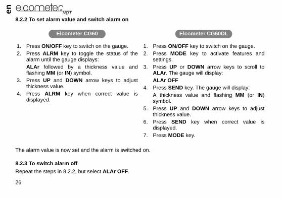
• CLr in the display, indicating that the memory location is empty• ObSt (obstruct) in the display, indicating that a measurement could
7. Press the UP / DOWN arrow keys to advance to the desired memory
9.2 STORING A MEASUREMENT1. Take a measurement and press the SEND key to store a reading in th
The data logger will then automatically advance to the next memory2. Repeat step 1 as required.
9.3 DELETING CONTENTS OF A MEMORY LOCATIONThe user may require a memory location that is currently full to be over wr(clearing) the contents of the memory location is outlined in the following s
Note: This procedure assumes the steps in 9.1 and 9.2 have been comple
1. Press the UP / DOWN arrow keys to move to the memory location to bIf the memory location is currently full, the display will flash the FuLL s
2. Press the CLR key to delete the contents of the memory location. Thlocation (L011, L099, etc.) and the CLr symbol.
3. Take another measurement, and press the SEND key to write to cleared.

en
easurements. This would allow01, for example. The procedure
d of all measurements. flash FILE F-05 (or the batch
batch selected). CLr?
CG60_CG60DL_TMA_0498_00_01_23225_A6L.fm Page 30 Tuesday, November 22, 2011 12:19 PM
30
9.4 DELETING CONTENTS OF AN ENTIRE BATCHThe user may require the contents of an entire batch to be cleared of all mthe user to start a new list of measurements starting at memory location L0is outlined in the following steps:1. Press ON/OFF key to switch on the gauge.2. Press MEM key to activate the data logging functions and settings.3. Press SEND key to enter batch setup.4. Press UP / DOWN arrow keys to scroll to the batch that is to be cleare5. Press SEND key once again to select the batch. The display will
selected).6. Press UP / DOWN arrow keys to scroll to the flashing CLr F-05 (or the7. Press SEND key to select the clear batch option. The display will show8. Press CLR key to confirm and clear the contents of the entire batch.9. Press MEM key at any time to exit data logging functions.
9.5 DELETING CONTENTS OF ALL BATCHES1. Press ON/OFF key to switch on the gauge.2. Immediately press the CLR key. The display will show CLr?3. Press CLR key once again to clear all batches.
31
en
to a computer. The Model CG60r readings as they are taken and
cable is supplied with the Modelsee “Spares” on page 38).meterndt.com but other types of
er cable into the COM port on the
RS232 data connection socket
R
PRB0
ONOFF
INMMINMM
RS232 data connection socket
CG60_CG60DL_TMA_0498_00_01_23225_A6L.fm Page 31 Tuesday, November 22, 2011 12:19 PM
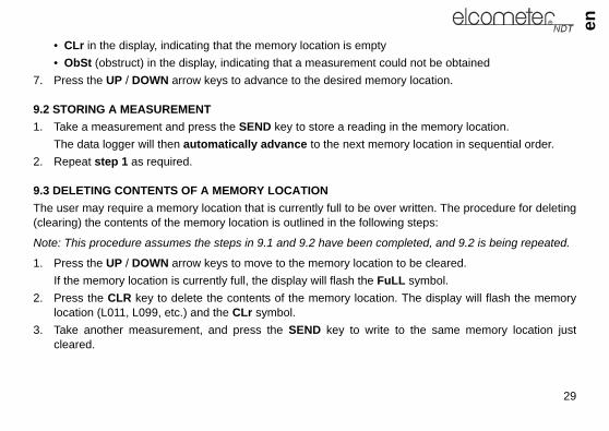
10 TRANSFERRING READINGS TO A COMPUTER
Readings can be transferred from the Model CG60 and Model CG60DLwill transfer readings as they are taken. The Model CG60DL will transfealso transfer the contents of its memory.A data transfer cable is used to connect the gauge to the computer. ThisCG60DL and is available as an optional accessory for the Model CG60 (Elcometer recommends the use of NDT Link available from www.elcosoftware may also be used.
10.1 CONNECTING THE DATA TRANSFER CABLE1. Plug the 9-pin female D-type connector on one end of the data transf
PC, or USB to COM adapter.2. Plug the jack connector on the other end of the data transfer
cable into the RS232 data connection socket on the bottomof the gauge (Figure 7).
3. Start the communications software.4. Select gauge type Elcometer CG60 or CG60DL.
Figure 7.

en
ent to the computer.
- see “Transferring readings to a
to the computer.l flash FILE F-05 (or the batch
cted) flashing on the display.lay will show buSY during data
CG60_CG60DL_TMA_0498_00_01_23225_A6L.fm Page 32 Tuesday, November 22, 2011 12:19 PM
32
10.1.1 Transferring dataModel CG60After taking a measurement, press the SEND key to send the measurem
Model CG60DLFollow the instructions in “Measurement options” on page 23
10.1.2 Transferring one batch1. Connect the gauge to a computer and start the data transfer software
computer” on page 31.2. Press ON/OFF key to switch on the gauge.3. Press MEM key to activate the data logging functions and settings.4. Press SEND key to enter batch setup.5. Press UP / DOWN arrow keys to scroll to the batch that is to be sent 6. Press SEND key once again to select the batch. The display wil
selected).7. Press UP / DOWN arrow keys to scroll to LISt F-05 (or the batch sele8. Press the SEND key to send readings to the computer. The disp
transfer. Wait until all the data has been transferred.9. Press the MEM key to exit the data logging functions.

33
en
.
display.
y. If the display is heated abovege is left in a car parked in strong
teries and store them separately.batteries.
CG60_CG60DL_TMA_0498_00_01_23225_A6L.fm Page 33 Tuesday, November 22, 2011 12:19 PM
10.1.3 Transferring all batches1. Connect the gauge to a computer and start the data transfer software2. Press ON/OFF key to switch on the gauge.3. Press MEM key to activate the data logging functions and settings.4. Press UP / DOWN arrow keys to scroll to SEnd ALL flashing on the 5. Press the SEND key to send readings to the computer.
The display will show buSY during data transfer.Wait until all the data has been transferred.
6. Press the MEM key to exit the data logging functions.
11 STORAGE
The Model CG60/CG60DL gauge has a Liquid Crystal Displa50°C (120°F) it may be damaged. This can happen if the gausunlight.
Always store the gauge in its case when it is not being used.If the gauge is to remain unused for long periods of time, remove the batThis will prevent damage to the gauge in the event of malfunction of the

en
ice under normal operating and
e number of measurements takenlways set the transducer down song the surface will reduce the lifelcometer NDT supplier or directly
likely event of a fault, the gaugeElcometer. The warranty will be
CG60_CG60DL_TMA_0498_00_01_23225_A6L.fm Page 34 Tuesday, November 22, 2011 12:19 PM
34
12 MAINTENANCE
The Model CG60/CG60DL is designed to give many years reliable servstorage conditions.
12.1 TransducerThe transducer will wear with repeated use. Transducer life depends on thand the manner in which readings are taken. To extend transducer life, athat it is perpendicular to the panel surface. Dragging the transducer aloof the transducer. Replacement transducers are available from your local Efrom Elcometer.
12.2 FaultsThe gauge does not contain any user-serviceable components. In the unshould be returned to your local Elcometer NDT supplier or directly to invalidated if the instrument has been opened.
13 TECHNICAL SPECIFICATION
13.1 PerformanceRange (pulse-echo): 0.63 mm to 500 mm (0.025" to 19.999")Range (echo-echo): 2.54 mm to 25.4 mm (0.1" to 1.0")Resolution: 0.01 mm (0.001")Accuracy: ±0.1 mm (±0.004"), depends on material and conditions

35
en
ic conditions)
caps
quivalents
tamination. Please consult your local
ble batteries. Follow the instructionsable batteries.
CG60_CG60DL_TMA_0498_00_01_23225_A6L.fm Page 35 Tuesday, November 22, 2011 12:19 PM
Sound-velocity range: 1250 m/s to 10 000 m/s (0.0492 in/μs to 0.3937 in/μs)Physical Weight: 295 g (10 oz) including batteries
Size: 63.5 mm x 120.6 mm x 31.5 mm (2.5" x 4.5" x 1.24")
Operating temperature: -30°C to 50°C (-20°F to 120°F) (depending upon climat
Case: Extruded aluminium body, Nickel plated aluminium end
13.2 KeypadType: Sealed membrane
Properties: Resistant to water and petroleum products
13.3 Power supplyType: Internal batteries
Battery type: 2 x LR6 (AA), alkalinea dry batteries or rechargeableb e
Battery life: 200c hours continuous (alkaline dry batteries)
a. Alkaline batteries must be disposed of carefully to avoid environmental conenvironmental authority for information on disposal in your region.Do not dispose of any batteries in fire.
b. Rechargeable batteries can be used if they are charged outside the gauge.c. Battery life is reduced to approximately 120 hours when using rechargea
provided by the battery manufacturer when charging and disposing of recharge
en
onic gauges against defects innd user.st such defects for a period of 90such defects during the warrantys that prove to be defective. The
a reasonable amount of time, therice upon return of the product.
r inadequate maintenance by the environmental specifications for
espect to this product. Elcometer fitness for a particular purpose. implied warranty, so the abovety of merchantability or fitness is
ther rights, which may vary from
CG60_CG60DL_TMA_0498_00_01_23225_A6L.fm Page 36 Tuesday, November 22, 2011 12:19 PM
36
14 WARRANTY
Elcometer NDT warrants the Model CG60 and Model CG60DL ultrasmaterials and workmanship for a period of two years from receipt by the eAdditionally, Elcometer NCT warrants transducers and accessories againdays from receipt by the end user. If Elcometer NDT receives notice of period, Elcometer NDT will either, at its option, repair or replace productwarranty will be invalidated if the instrument has been opened.Should Elcometer NDT be unable to repair or replace the product within customer's alternative exclusive remedy shall be refund of the purchase p
14.1 ExclusionsThe above warranty shall not apply to defects resulting from: improper ocustomer; unauthorised modification or misuse; or operation outside thethe product.Elcometer NDT makes no other warranty, either express or implied, with rNDT specifically disclaims any implied warranties of merchantability orSome states or provinces do not allow limitations on the duration of anlimitation or exclusion may not apply to you. However, any implied warranlimited to the two-year duration of this written warranty.This warranty gives you specific legal rights, and you may also have ocountry to country, state to state or province to province.

37
en
NDT and arrange for servicing of
llowing methods:
r NDT for details of the services
CG60_CG60DL_TMA_0498_00_01_23225_A6L.fm Page 37 Tuesday, November 22, 2011 12:19 PM
14.2 Obtaining service during warranty periodIf your hardware should fail during the warranty period, contact Elcometerthe product. Retain proof of purchase in order to obtain warranty service.For products that require servicing, Elcometer NDT may use one of the fo• Repair the product• Replace the product with a re-manufactured unit• Replace the product with a product of equal or greater performance• Refund the purchase price.
14.3 After the warranty periodIf your hardware should fail after the warranty period, contact Elcometeavailable, and to arrange for non-warranty service.

en
quired to get started and takehe gauge replacement items may from your local Elcometer NDT
ales Part No.X2M25CP-2X5M00CP-4X5M00CP-10X7M50CP-6X10M0CP-4C-24034-1C-24034-2C-24034-4C-24034-5
age 38 for further details.
asurements on a wide range ofaterial, however, have different
of transducers which should be
CG60_CG60DL_TMA_0498_00_01_23225_A6L.fm Page 38 Tuesday, November 22, 2011 12:19 PM
38
15 SPARES
The Model CG60/CG60DL gauge is complete with all the items remeasurements (transducers must be ordered separately). Over the life of tbe required. The following replacement and optional items are availablesupplier or directly from Elcometer.
Description S2.25 MHz 1/4” Potted Side Transducer T5 MHz 1/4” Potted Side Transducer T5 MHz 1/4” Potted Side High Damped Transducer T7 MHz 1/4” Potted Side High Damped Transducer T10 MHz 1/4” Potted Side Transducer TUltrasonic Couplant, 120 ml (4 oz) TUltrasonic Couplant, 360 ml (12 oz) TUltrasonic Couplant, High Temperature 340°C (650°F), 60 ml (2 oz) TUltrasonic Couplant, High Temperature 480°C (896°F), 60 ml (2 oz) T
A wide range of other transducers are available - see “Transducers” on p
16 TRANSDUCERS
The Model CG60 and Model CG60DL are capable of performing mematerials, from various metals to glass and plastics. Different types of mproperties. The following paragraphs highlight the important propertiesconsidered when assessing a particular measurement task.

39
en
gy is sent into the material being
utlined below:
. Initial signal strength is largely aitting area will send more energy6 mm (1/4”) transducer will emit a
aterials through which the soundring. Both of these effects reduce
ound of a lower frequency. It mayr in every instance, however low
ine the suitability of a transducerined areas. Also, the surface area a curved surface may require the
CG60_CG60DL_TMA_0498_00_01_23225_A6L.fm Page 39 Tuesday, November 22, 2011 12:19 PM
The best measurement condition is one where sufficient ultrasonic enermeasured such that a strong, stable echo is received by the gauge.Several factors affect the strength of ultrasound as it travels. These are o
16.1 INITIAL SIGNAL STRENGTHThe stronger a signal is to begin with, the stronger its return echo will befactor of the size of the ultrasound emitter in the transducer. A large eminto the material being measured than a small emitting area. Therefore a stronger signal than a 3 mm (1/8”) transducer.
16.2 ABSORPTION AND SCATTERINGAs ultrasound travels through any material, it is partly absorbed. If the mtravels have any grain structure, the sound waves will experience scattethe strength of the waves.Higher frequency ultrasound is absorbed and scattered more than ultrasseem therefore that using a lower frequency transducer might be bettefrequencies are less directional than high frequencies.
16.3 GEOMETRY OF THE TRANSDUCERThe physical constraints of the measuring environment sometimes determfor a given job. The transducer may simply be too large to be used in confavailable for contacting with the transducer may be limited. Measuring onuse of a transducer with a matching curved wearface.

en
y hot, special high-temperaturerforming a ‘Calibration to Knownces” on page 44.
rements, including:
sducer head.r head by a connector - allows
meet your application, taking into
a range of measurement tasks:
CG60_CG60DL_TMA_0498_00_01_23225_A6L.fm Page 40 Tuesday, November 22, 2011 12:19 PM
40
16.4 TEMPERATURE OF THE MATERIALWhen it is necessary to measure on surfaces that are exceedingltransducers may be necessary. Additionally, care must be taken when peThickness’ with a high temperature application - see “Measuring hot surfa
16.5 SELECTING THE CORRECT TRANSDUCERElcometer NDT have a complete range of transducers to meet your requi• A range of frequencies and sizes• Straight and right angle• Transducers available as potted or microdot transducers:
Potted transducers - transducer cable is permanently fixed to the tranMicrodot transducers - transducer cable is fixed to the transducetransducer heads to be replaced quickly and easily.
• High temperature transducers - temperature up to 480ºC (896ºF)When selecting a transducer, it is important to choose one which will bestconsideration:• The measurement range• The type of material to be tested• The design of the transducer probe typeThe following table gives guidance on the type of transducer required for

41
en
es
er diameters offer greater etration power because of the tal size, for difficult to measure erials.
lower frequencies for greater etration and use higher uencies for better resolution.se transducers are suitable for in both pulse-echo and echo- modes. This enables you to sure overall material thickness g the Echo-echo mode, and then ch to pit detection mode (Pulse-) without changing transducers.
CG60_CG60DL_TMA_0498_00_01_23225_A6L.fm Page 41 Tuesday, November 22, 2011 12:19 PM
Material being measured Mode Transducer type
required Not
High penetrationplastics andcastings
PULSE-ECHO(P-E)
Cast iron - 1MHz to 5MHz transducer.Cast aluminium - 10MHz transducer.Plastics typically require lower frequency transducers depending on the thickness and make-up of the material.
Largpencrysmat
Corrosion and pitdetection in steeland cast materials
PULSE-ECHO(P-E)
Typically a 5MHz transducer or higher is required.
Usepenfreq
Material thickness measured through a coating
ECHO-ECHO(E-E)
Special high damped transducers are required; typically the 3.5MHz, 5MHz, and 7.5MHz hi damped transducers.
Theuse echomeausinswitecho

en
higher frequencies provide ter resolution and a lower mum thickness rating overall.
-echo mode will eliminate error ed by temperature variations in elay line of the transducer.rials such as titanium, stainless
l, and aluminium may produce ce noise. This is a signal that ars at the surface of the rial when using a dual element
y line probe.
s
CG60_CG60DL_TMA_0498_00_01_23225_A6L.fm Page 42 Tuesday, November 22, 2011 12:19 PM
42
Thin materials PULSE-ECHO(P-E)
High frequency transducers are required; typically the 7.5MHz and 10MHz models with extra resolution.
The greamini
High temperature PULSE-ECHOandECHO-ECHO
Special 2.25MHz and 5 MHz High temperature transducers are required.
Echocausthe d
Noisy material Select a higher frequency transducer to reduce this noise - 7.5MHz and higher for better resolution.
Matesteesurfaappematedela
Measuring extreme curvatures or areas of restricted access
Higher frequency transducers with smaller diameters are required.The smallest diameter uses 3/16" crystals with a contact area of .250"
Material being measured Mode Transducer type
required Note

43
en
nce when carrying out ultrasonicrasound through the material, and
cles, rust, or scale. The presencegainst the surface. Often, a wireases, rotary sanders or grindingouging, which will inhibit proper
t iron, will prove most difficult tos acts on light, the beam becomes
tribute to excessive wear of thelong the surface.
all, orientation of the transducers
CG60_CG60DL_TMA_0498_00_01_23225_A6L.fm Page 43 Tuesday, November 22, 2011 12:19 PM
17 CONDITION AND PREPARATION OF SURFACES
The shape and roughness of the test surface are of paramount importathickness testing. Rough, uneven surfaces may limit the penetration of ultresult in unstable, and therefore unreliable, measurements.The surface being measured should be clean, and free of any small partiof such obstructions will prevent the transducer from seating properly abrush or scraper will be helpful in cleaning surfaces. In more extreme cwheels may be used, though care must be taken to prevent surface gtransducer coupling.Extremely rough surfaces, such as the pebble-like finish of some casmeasure. These kinds of surfaces act on the sound beam like frosted glasdiffused and scattered in all directions.In addition to posing obstacles to measurement, rough surfaces contransducer, particularly in situations where the transducer is ‘scrubbed’ a
18 APPLICATION NOTES
18.1 MEASURING TUBINGWhen measuring a piece of pipe to determine the thickness of the pipe wis important.

ensurements should be made with
at right angles) to the long axis of
med, one with the wearface gap the long axis of the pipe (Figure
hickness at that point.
eter pipe
of the material. As materials heatth surface temperatures less than At temperatures above 100°Cstarts to have a noticeable effect
rm a calibration procedure (seeat, or near, the temperature of thethe velocity of sound through the
CG60_CG60DL_TMA_0498_00_01_23225_A6L.fm Page 44 Tuesday, November 22, 2011 12:19 PM
44
If the diameter of the pipe is larger than approximately 100 mm (4”), meathe transducer oriented so that the gap in the wearface is perpendicular (the pipe.If the diameter of the pipe is small, two measurements should be perforperpendicular to the long axis of the pipe, another with the gap parallel to8). The smaller of the two displayed values should then be taken as the t
Figure 8. Transducer positioning on small diam
18.2 MEASURING HOT SURFACESThe velocity of sound through a material depends upon the temperature up, the velocity of sound in the material decreases. In most applications wiapproximately 100°C (~200°F), no special procedures are required.(~200°F), the change in sound-velocity of the material being measured upon the accuracy of ultrasonic measurement.At such elevated temperatures, it is recommended that the user perfo“Calibration” on page 17) on a sample piece of known thickness, which is material to be measured. This will allow the gauge to correctly calculate hot material.
Perpendicular Parallel

45
en
ssary to use a high-temperaturethe surface for as short a time asact with a hot surface, it will begindversely affect the accuracy of
ry considerably from one piece to in sound-velocity across a singleing a calibration procedure on ae a part of the same piece being each test piece individually, the
ps or pockets within the laminatease in thickness in an otherwiseaterial thickness, it does provide
paint/coating may be significantlyn example of this would be a mildThe sound-velocity of the pipe is/s (.0900 in/µsec). If the gauge is
CG60_CG60DL_TMA_0498_00_01_23225_A6L.fm Page 45 Tuesday, November 22, 2011 12:19 PM
When performing measurements on hot surfaces, it may also be necetransducer. It is recommended that the transducer be left in contact with needed to acquire a stable measurement. While the transducer is in contto heat up, and through thermal expansion and other effects, may ameasurements.
18.3 MEASURING LAMINATED MATERIALSThe density (and therefore sound-velocity) of laminated materials may vaanother. Some laminated materials may even exhibit noticeable changessurface. The only way to reliably measure such materials is by performsample piece of known thickness. Ideally, this sample material should bmeasured, or at least from the same lamination batch. By calibrating toeffects of variation of sound-velocity will be minimised.An additional consideration when measuring laminates, is that any air gawill reflect the ultrasound beam. This will be noticed as a sudden decreregular surface. While this may impede accurate measurement of total mpositive indication of air gaps in the laminate.
18.4 MEASURING THROUGH PAINT AND COATINGSWhen measuring through paints and coatings the sound-velocity of the different from the sound-velocity of the actual material being measured. Asteel pipe with approximately 0.6 mm (.025") of coating on the surface. 5918 m/s (.2330 in/µsec), and the sound-velocity of the paint is 2286 m

entual coating thickness will appearound-velocity.asurements for applications suchd entirely and the steel will be the
Soundvelocity (m/s)
Soundvelocity (in/µs)
2210 0.0873962 0.1562692 0.1062337 0.0925842 0.230 (Approx.)2388 0.0945639 0.2222311 0.0913607 0.1425918 0.2335664 0.2236985 0.275 (Approx.)1422 0.056
CG60_CG60DL_TMA_0498_00_01_23225_A6L.fm Page 46 Tuesday, November 22, 2011 12:19 PM
46
calibrated for mild steel pipe and measures through both materials, the acto be 2.5 times thicker than it actually is, as a result of the differences in sThe error can be eliminated by using the echo-echo mode to perform meas these. In echo-echo mode, the paint/coating thickness will be eliminateonly material measured.
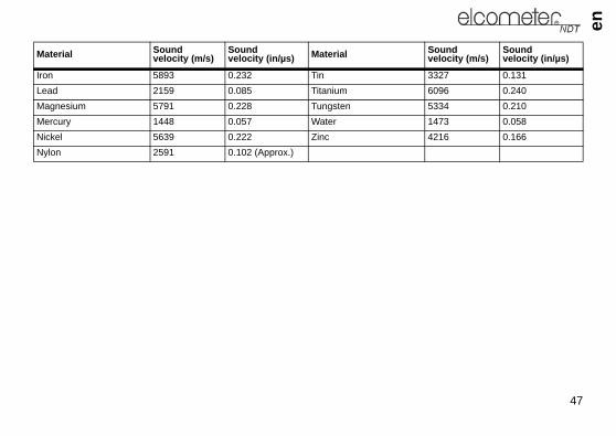
19 SOUND VELOCITIES OF COMMON MATERIALS
Material Soundvelocity (m/s)
Soundvelocity (in/µs) Material
Aluminium 6350 0.250 ParaffinBismuth 2184 0.086 PlatinumBrass 4394 0.173 PlexiglasCadmium 2769 0.109 PolystyreneCast Iron 4572 0.180 (Approx.) PorcelainConstantan 5232 0.206 PVCCopper 4674 0.184 Quartz GlassEpoxy Resin 2540 0.100 (Approx.) Rubber, VulcanisedGerman Silver 4750 0.187 SilverGlass, Crown 5664 0.223 SteelGlass, Flint 4267 0.168 Steel, StainlessGold 3251 0.128 StelliteIce 3988 0.157 Teflon
47
en
3327 0.1316096 0.2405334 0.2101473 0.0584216 0.166
Soundvelocity (m/s)
Soundvelocity (in/µs)
CG60_CG60DL_TMA_0498_00_01_23225_A6L.fm Page 47 Tuesday, November 22, 2011 12:19 PM
Iron 5893 0.232 TinLead 2159 0.085 TitaniumMagnesium 5791 0.228 TungstenMercury 1448 0.057 WaterNickel 5639 0.222 ZincNylon 2591 0.102 (Approx.)
Material Soundvelocity (m/s)
Soundvelocity (in/µs) Material