Embed Size (px)
Citation preview
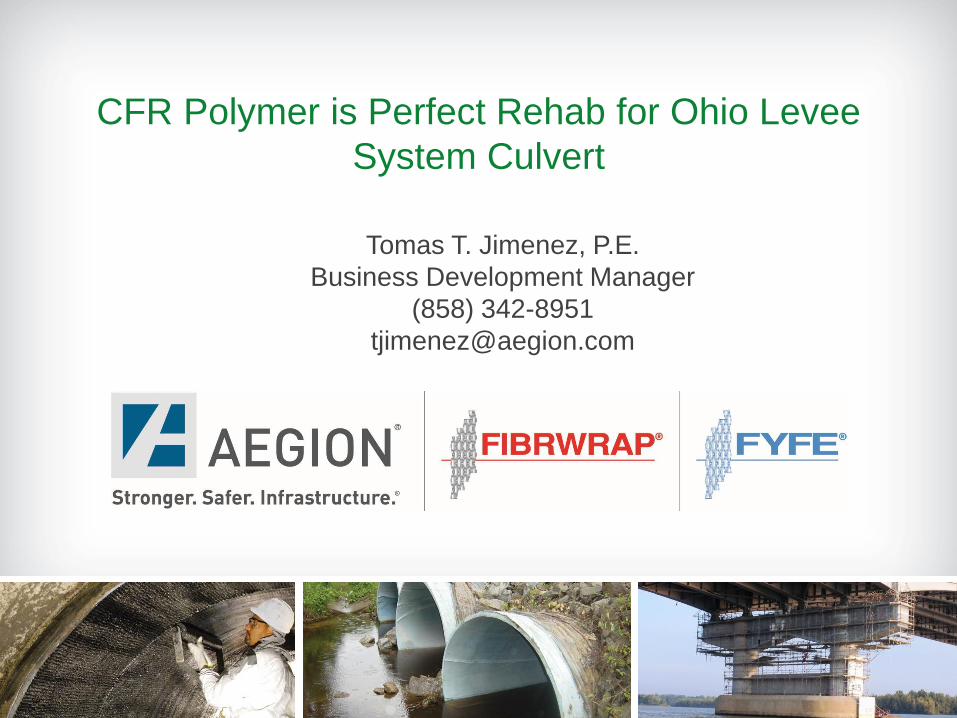
CFR Polymer is Perfect Rehab for Ohio Levee
System Culvert
Tomas T. Jimenez, P.E.
Business Development Manager
(858) 342-8951

Presentation Outline
Introduction to FRP
Project Background
Installation Inspection
Conclusion

Fiber-Reinforced Polymer (FRP)
The Tyfo® fiber-reinforced polymer (FRP) system are designed to increase
the structural performance of existing PCCP, RC and steel pipes.
Fibrwrap® Construction, an Aegion company, is the exclusive installer of
the Tyfo ® FRP pipeline repair system for pipelines.
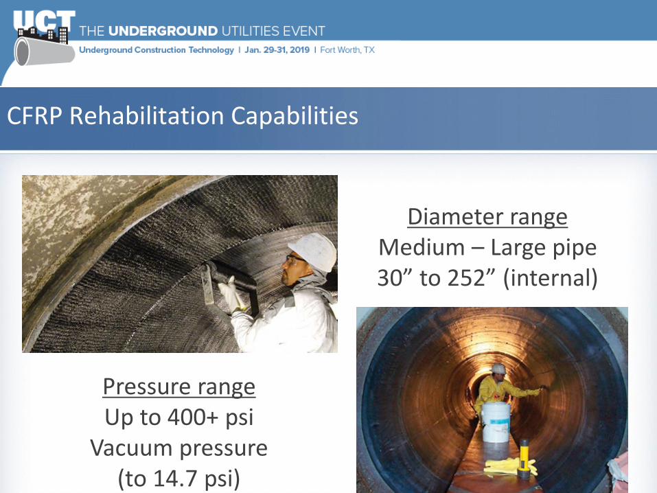
CFRP Rehabilitation Capabilities
Diameter rangeMedium – Large pipe 30” to 252” (internal)
Pressure rangeUp to 400+ psi
Vacuum pressure (to 14.7 psi)
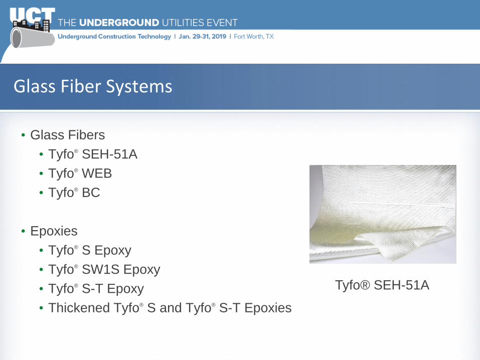
Glass Fiber Systems
• Glass Fibers
• Tyfo® SEH-51A
• Tyfo® WEB
• Tyfo® BC
• Epoxies
• Tyfo® S Epoxy
• Tyfo® SW1S Epoxy
• Tyfo® S-T Epoxy
• Thickened Tyfo® S and Tyfo® S-T Epoxies
Tyfo® SEH-51A

Tyfo® SCH Systems – Carbon Fiber Systems
• Carbon Fibers
• Tyfo® SCH-41
• Tyfo® SCH-41-2X
• Tyfo® SCH-Mark V
• Tyfo® SCH-11UP
• Tyfo® UC Strips
• Epoxies
• Tyfo® S Epoxy
• Tyfo® SW1S Epoxy
• Tyfo® S-T Epoxy
• Thickened Tyfo® S and Tyfo® S-T Epoxies
Tyfo® SCH-41 Tyfo® SCH-Mark V

Carbon Fiber Reinforced Polymer (CFRP): Properties are based on the fiber and durability is based on the polymer

Stress-Strain Behavior Illustrates Critical Design Principals

Typical CFRP Design Approach
• Consider degradation level of host pipe
• Stand-alone (fully structural design) versus composite design (with inner core)
• Use Load resistance factor design/AWWA C305 (LRFD)
Limit
State
Loads
CFRP
Rupture
(2)
1-Internal pressure
2-Internal pres. +
External Loads
Buckling External loads:
Groundwater +
Vacuum
Debonding Empty pipe under
external loads
Circumferential Design
Limit State Loads
CFRP
Rupture
Internal pressure
(Thrust, Poisson) +
Temperature
Debonding Internal pressure
(Thrust, Poisson) +
Temperature
Buckling Temperature
Longitudinal Design

FRP Codes-Reports-Design Guidelines
Code/ Report Code Title Date
AWWA C305CFRP Renewal and Strengthening of
PCCPDec-18
AWWA C304-04Prestressed Concrete Pressure Pipe,
Steel Cylinder TypeDec-07
AWWA M11Steel Water Pipe - A Guide for Design
and InstallationJul-04
ASME PCC-2Repair of Pressure Equipment and
PipingApr-11
ASME B31.1Power Piping (ASME Code for
Pressure Piping, B31)Jun-12

Uses of FRP Rehabilitation Systems
• Structural rehabilitation
• Segmental repairs
• Full length repairs
• Fully structural rehabilitation
• Single criteria requirement – pressure, transient, broken back, joint rehab
• Joint rehabilitation
• Leak remediation
• Structural strengthening
• Reinforced coating application
• Durable coating
• Nominal strength

Sand Blasting Equipment Finished Surface - Concrete
FRP Installation Method
STEP 1: SURFACE PREPARATION

CFRP Impregnation
Material TransportSurface Primer
FRP Installation Method
STEP 2: PRIMER / SATURATION
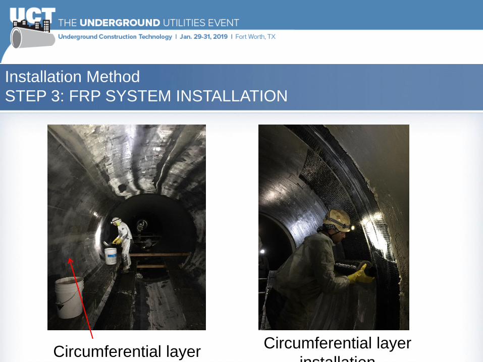
Circumferential layerCircumferential layer
installation
Installation Method
STEP 3: FRP SYSTEM INSTALLATION
QA/QC Process
• Continuous Inspection conducted by Quality Control Specialist (QCS)
• Selected QA/QC steps documented
• CFRP material manufactured by an ISO 9001:2015 certified company
• Verify installation is in accordance with drawings and specifications
• Condition of host pipe
• Control of air flow, temperature, and humidity
• Surface preparation
• Adhesion tests
• Material saturation
• Application (details, timing)
• Termination details
• Preparation of witness panels
• Post-installation inspection
• Curing (85% cure before service)
• Thickness measuring device

•Minimum (3) 2 ft x 2 ft panels on
adjacent non-repair pipes
•Prepared and tested by Installer
(ASTM D4541)
•Witnessed by Inspector
•>200 psi required for at least 3 tests
per panel
•Failure mode may affect design
approach!
In-Situ Quality Control TestingASTM D4541 – Adhesion Testing

Testing of Witness Panels after Construction
• Prepared by the Installer, witnessed by the Inspector,
tested by the Independent Testing Agency
• Three panels or one panel per day per work shift,
whichever is greater
• One layer of CFRP
• Preparation of panels spread throughout construction

Case Study – Zoar Levee
Unique Project Requirements
• 36” reinforced concrete box culvert rehabilitation
• Operated by US Army Corps of Engineers
• The box culvert structure is critical for dam safety
• Box culver joints were cracked and damaged due to service
conditions
• The FRP composite wrap was designed to prevent soil erosion
behind the culvert and to maintain dam integrity
• The FRP wrap was used in conjunction with concrete repairs
• The FRP wrap supported watertight requirements and nominal
strength requirements

Case Study – Zoar Levee
Ventilation and Dehumidification

Case Study – Zoar Levee
Unique Project Requirements
• Background and E-verify checks
• USACE safety practices
• Confined space entry plan and
rescue team
• Cleaning and jetting of culvert
• Pre and Post CCTV
• Ventilation
• Surface preparation
• Inspection and QC testing
(ASTM D3039 and D4541)
• Materials contain 0% VOC
• 22 joints repaired

Case Study – Zoar Levee
Unique Project Challenges
• Small site setup footprint
• No truck access was allowed on the levee walls and hence a CIPP
crew was not allowed to enter the site
• Hydraulic capacity requirement prevented the loss of cross sectional
area
• CIPP liners would reduce the culvert hydraulic capacity
• The USACE required a repair method to prevent sink holes at the
dam structure
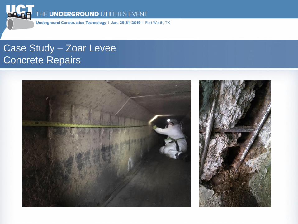
Case Study – Zoar Levee
Concrete Repairs
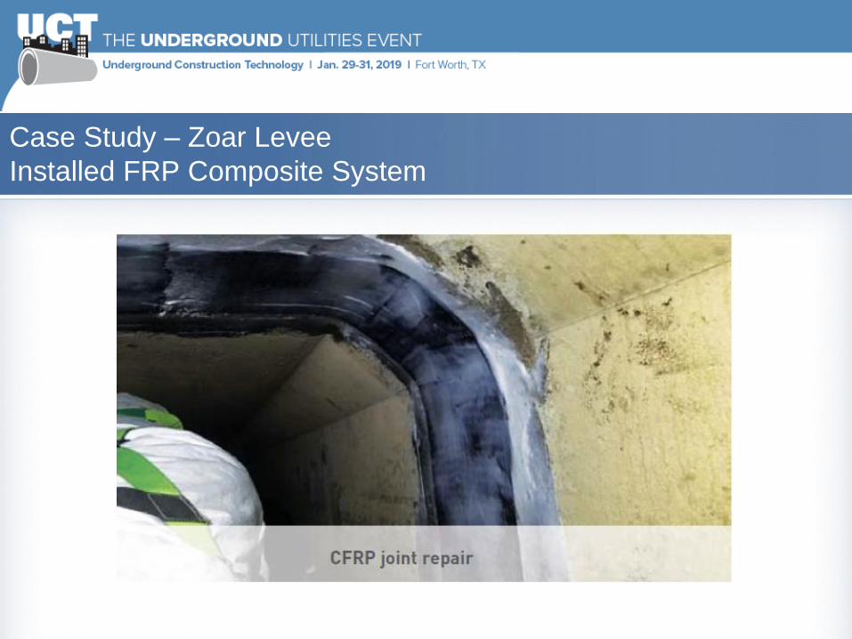
Case Study – Zoar Levee
Installed FRP Composite System

Case Study – Zoar Levee
FRP Material Inspection

Conclusions
• Unique box culvert structure was successfully rehabilitated with FRP
materials
• Joint rehabilitation or spot repairs for pipes or box culverts can be
cost effectively rehabilitated with FRP materials
• The concrete repairs and FRP materials effectively provide the leak
prevention and nominal strengthening required by project
• The project team was able to support all required safety, quality
control, logistics and structural criteria
• The project team delivered the project on time and on budget
Thank you!
Tomas T. Jimenez, P.E.
Business Development Manager
Cell. 858-342-8951