Embed Size (px)
Citation preview

ICEBO2006, Shenzhen, China HVAC Technologies for Energy Efficiency Vol.IV-3-3
CFD Simulation and Analysis of the Combined Evaporative Cooling and
Radiant Ceiling Air-conditioning System
Huang Xiang Li Yinming Wu Junmei
Xi’an Polytechnic University
Xi’an, P.R.China,
Abstract: Due to such disadvantages as large air duct and high energy consumption of the current all- outdoor air evaporative cooling systems used in the dry region of Northwest China, as well as the superiority of the ceiling cooling system in improving thermal comfort and saving energy, a combined system is presented in this paper. It combines an evaporative cooling system with ceiling cooling, in which the evaporative cooling system handles the entire latent load and one part of the sensible loads, and the ceiling cooling system deals with the other part of sensible loads in the air-conditioned zone, so that the condensation on radiant panels and the insufficiency of cooling capacity can be avoided. The cooling water at 18℃ used in the cooling coils of ceiling cooling system can be ground water, tap water or the cooled water from cooling towers in the summer.
This new air-conditioning system and existing all- outdoor air evaporative cooling system are applied to a project in the city of Lanzhou. Energy consumption analysis of the building is carried out using the energy consumption code. Velocity and temperature distribution in the air-conditioned zone is computed using CFD. According to the results, the energy consumption and indoor human thermal comfort of both systems are then compared. It is concluded that the new system occupies less building space, reduces energy consumption, improves indoor human thermal comfort and saves initial investment. Key words: evaporative cooling, radiant ceiling, energy consumption analysis, CFD, thermal comfort
1. INTRODUCTION With the development of computer technology,
CFD is widely used in the energy consumption analysis and simulation of fluid fields in HVAC. Now, a new air-conditioning system and the existing all outdoor air evaporative cooling system is applied to an project in the city of Lanzhou respectively. Energy consumption analysis of the building is carried out using energy consumption code and velocity and temperature distribution in the air-conditioned zone is computed using CFD.
2. OBJECT OF STUDY 2.1 Radiant ceiling and evaporative cooling
air-conditioning systems Evaporative cooling is widely used in northwest
area of China such as Xinjiang province, It shows good effects including good indoor air quality, environment protecting and energy saving compared with the traditional mechanical cooling in most public and civil buildings, such as hotel, office building, restaurant, amusement, gymnasium, cinema, and some industrial buildings. However, there exists such problems as with large air ducts[2,3] and can not control every room independently to meet the different need in the existing all outdoor air evaporative cooling system(named system 1), as shown in Fig.1. The feasible cooling water can be generated to supply to ceiling cooling system by using an unit composed of indirect evaporative cooling and cooling towers because of the local suitable climate. To inherit the advantages of So the ceiling cooling and evaporative cooling system, a composed system shown in Fig.2(named system1) is
ESL-IC-06-11-90
Proceedings of the Sixth International Conference for Enhanced Building Operations, Shenzhen, China, November 6 - 9, 2006

ICEBO2006, Shenzhen, China HVAC Technologies for Energy Efficiency Vol.IV-3-3
presented.The evaporative cooling system affords the whole latent loads and one part of sensible loads, and the ceiling cooling system deals with other part of sensible loads in the air-conditioned zone, so the condensation on radiant panels and the insufficiency of cooling capacity can be avoided. The cooling water at 18℃ in the cooling coils of ceiling cooling system can be the ground water, tap water and cooled water from cooling water units in summer[4].
Fig.1 System 1
Fig.2 System 2
The energy consumption and indoor thermal comfort of the building using the combined air-conditioning system will be analyzed by comparing with that of the existing all outdoor air evaporative cooling system. 2.2 Outline of the office
To compare the performances in thermal comfort and energy consumption of the above two different air conditioning systems, a typical office room in anorth-facing five-storied building in the city of Lanzhou in China is simulated in this study. The
office room is located in middle story with sizes of 12m long, 6.3m wide, and 2.8m high. The total thickness of the wall structure is 240mm and the heat transfer coefficient U is 1.136 Kmw ⋅2 . The area of double-pane windows is 14.4m2 , the U value is 2.3
Kmw ⋅2 . The north wall is facing to outside and the south wall is adjacent to a corridor.
Because the cooling to indoor air is mainly by radiation in the room with system 2, the comfortable temperature people feel may be 2� lower than the real indoor air temperature.So the designed temperature in the room with system 2 is 2� higher than that with system 1.
3. CFD MODEL 3.1 Physical Model
Fig.3 The office room model with the system 1
Fig.4 The office model with the system 2
(1) To simplify the physical model, the shape of
indoor lamps is simplified to be cuboid with be cuboid with sizes of 1.2m long, 0.6m wide, and 0.02m high, the sizes of the indoor computer is 0.4m long, 0.4m wide, and 0.26m high, the sizes of person seated in a chair is 0.35m long, 0.4m wide, and 1.1m high. Cooling load from one human body and one computer is 58.5W(sensible heat is considered only) and 129KW[5], respectively. Cooling capacity from radiant ceiling is 112W/m2.
(2) Heat gain through the envelopes of room by radiation and conduction is considered.
(3) Ceiling diffusers are used to supply air[6].
ESL-IC-06-11-90
Proceedings of the Sixth International Conference for Enhanced Building Operations, Shenzhen, China, November 6 - 9, 2006

ICEBO2006, Shenzhen, China HVAC Technologies for Energy Efficiency Vol.IV-3-3
(4) Latent heat from person is not considered. The resulting physical models corresponding to
the system1 and 2 are as in Fig. 3 and 4. 3.2 Computational Model 3.2.1 Governing Equations
The range of Reynolds numbers in the computation condition is from 2100 to 3453. The indoor air flow is taken as steady incompressible flow. The governing equations include Based on turbulence property of air in this paper, zero equation is used[7,8]. 3.2.2 Boundary Conditions
Firstly, the designing computations of system 1 and system2 to the office room are carried out to obtain the working conditions of system1 and system2, respectively.
For system 1: supply air temperature is 19.2�, supply air flow of a diffuser is 0.113m3/s, heat transfer through outside wall is 179.75W, cooling loads through windows by radiation and conduction are 397.81W and 119.23W, respectively.
For system 2: Supply air temperature is 21�, supply air flow of a diffuser is 0.0406m3/s, heat transfer through outside wall is 99.11W,cooling loads through windows by radiation and conduction are 397.81W and 52.99W, respectively. The cooling loads from other objects such as lamp, computer and human body can refer to 3.1.
3.3 Numerical Methods
To improve the accuracy of the numerical results, the grid density near the heat sources is fine[9] because of local large temperature gradient and velocity gradient Tab. 1 Discretization schemes and sub-relaxation
factors of both models terms pressure energy momentum
discretization scheme
standard two-order upwind
two-order upwind
sub-relaxation factor
0.3 1.0 0.7
Finite volume method is used to discrete governing equations. Discretization schemes and sub-relaxation factors are shown in table 1. The convergence criterion for the velocity is that the maximum mass residual of the cells divided by the
maximum residual of the first 5 iterations is less than 10-4, and after that, the residuals of momentum and energy equations are all less than 10-6. 3.4 Simulated Results and Analysis
The simulated results are shown in Fig. 5-12. Fig.5 and 6 show the temperature and velocity distribution near the human body in the vertical direction in the office with system 1 and system 2. Horizontal distribution of temperature and velocity in the office with system 1 and system 2 is shown in Fig. 7 and 8. Comparison of thermal comfort in the office with system 1 and system 2 is shown in Fig. 9 -12.
Fig.5 Temperature distribution in the vertical direction
Fig. 6 Velocity distribution in the vertical direction
a. system 1
ESL-IC-06-11-90
Proceedings of the Sixth International Conference for Enhanced Building Operations, Shenzhen, China, November 6 - 9, 2006

ICEBO2006, Shenzhen, China HVAC Technologies for Energy Efficiency Vol.IV-3-3
b.system2 Fig. 7 Temperature distributions at mz 2=
Conclusions are drawn as: (1)It is found that 31.01.1 ≤−t from Fig. 5 and 7 at x=3.55m, z=0.78m , it satisfies the Code for design of heating ventilation and air conditioning GB 50019-2003. Because of the heat transfers between the ceiling panel and indoor air through radiation and convection in the office with system 2, the temperature gradient in the room with system 2 is less than that with system 1, and thermal comfort in the room with system 2 is improved.
a. system 1
b. system 2
Fig. 8 Velocity distributions at my 1.1=
(2)Because of heat transfer between the ceiling panel and indoor air through diaion and convection in the office with system 2, the supplying air flow decreases
greatly, air velocity in the office room with system 2 meets the item listed in the Code for design of heating ventilation and air conditioning GB 50019-2003 , while air velocity in the office room with system 1 does not meet it from Fig. 6 and 8.
Fig. 9 PMV distribution in the x direction
Fig.10 PPD distribution in the x direction
a. system 1
b. system 2 Fig. 11 PMV distribution at the plane my 1.1=
ESL-IC-06-11-90
Proceedings of the Sixth International Conference for Enhanced Building Operations, Shenzhen, China, November 6 - 9, 2006
ICEBO2006, Shenzhen, China HVAC Technologies for Energy Efficiency Vol.IV-3-3
a. system 1
b. system 2
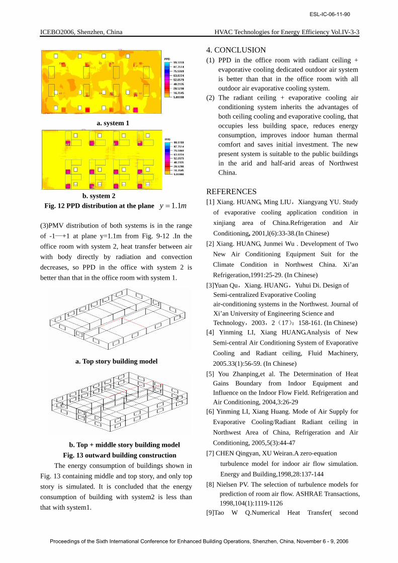
Fig. 12 PPD distribution at the plane my 1.1=
(3)PMV distribution of both systems is in the range of -1—+1 at plane y=1.1m from Fig. 9-12 .In the office room with system 2, heat transfer between air with body directly by radiation and convection decreases, so PPD in the office with system 2 is better than that in the office room with system 1.
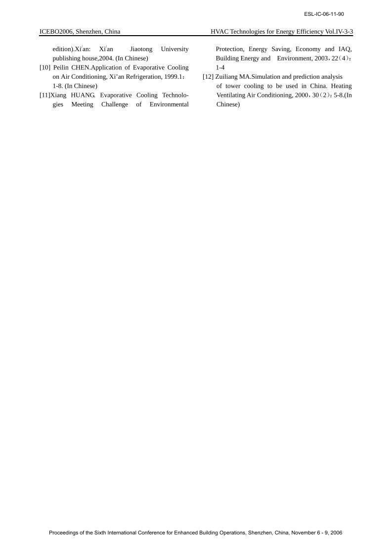
a. Top story building model
b. Top + middle story building model Fig. 13 outward building construction The energy consumption of buildings shown in
Fig. 13 containing middle and top story, and only top story is simulated. It is concluded that the energy consumption of building with system2 is less than that with system1.
4. CONCLUSION (1) PPD in the office room with radiant ceiling +
evaporative cooling dedicated outdoor air system is better than that in the office room with all outdoor air evaporative cooling system.
(2) The radiant ceiling + evaporative cooling air conditioning system inherits the advantages of both ceiling cooling and evaporative cooling, that occupies less building space, reduces energy consumption, improves indoor human thermal comfort and saves initial investment. The new present system is suitable to the public buildings in the arid and half-arid areas of Northwest China.
REFERENCES [1] Xiang. HUANG, Ming LIU,Xiangyang YU. Study
of evaporative cooling application condition in xinjiang area of China.Refrigeration and Air Conditioning, 2001,l(6):33-38.(In Chinese)
[2] Xiang. HUANG, Junmei Wu . Development of Two New Air Conditioning Equipment Suit for the Climate Condition in Northwest China. Xi’an Refrigeration,1991:25-29. (In Chinese)
[3]Yuan Qu,Xiang. HUANG,Yuhui Di. Design of Semi-centralized Evaporative Cooling air-conditioning systems in the Northwest. Journal of Xi’an University of Engineering Science and Technology,2003,2(17):158-161. (In Chinese)
[4] Yinming LI, Xiang HUANG.Analysis of New Semi-central Air Conditioning System of Evaporative Cooling and Radiant ceiling, Fluid Machinery, 2005.33(1):56-59. (In Chinese)
[5] You Zhanping,et al. The Determination of Heat Gains Boundary from Indoor Equipment and Influence on the Indoor Flow Field. Refrigeration and Air Conditioning, 2004,3:26-29
[6] Yinming LI, Xiang Huang. Mode of Air Supply for Evaporative Cooling/Radiant Radiant ceiling in Northwest Area of China, Refrigeration and Air Conditioning, 2005,5(3):44-47
[7] CHEN Qingyan, XU Weiran.A zero-equation turbulence model for indoor air flow simulation. Energy and Building,1998,28:137-144
[8] Nielsen PV. The selection of turbulence models for prediction of room air flow. ASHRAE Transactions, 1998,104(1):1119-1126
[9]Tao W Q.Numerical Heat Transfer( second
ESL-IC-06-11-90
Proceedings of the Sixth International Conference for Enhanced Building Operations, Shenzhen, China, November 6 - 9, 2006
ICEBO2006, Shenzhen, China HVAC Technologies for Energy Efficiency Vol.IV-3-3
edition).Xi/an: Xi/an Jiaotong University publishing house,2004. (In Chinese)
[10] Peilin CHEN.Application of Evaporative Cooling on Air Conditioning, Xi’an Refrigeration, 1999.1:1-8. (In Chinese)
[11]Xiang HUANG. Evaporative Cooling Technolo- gies Meeting Challenge of Environmental
Protection, Energy Saving, Economy and IAQ, Building Energy and Environment, 2003,22(4):1-4
[12] Zuiliang MA.Simulation and prediction analysis of tower cooling to be used in China. Heating Ventilating Air Conditioning, 2000,30(2):5-8.(In Chinese)
ESL-IC-06-11-90
Proceedings of the Sixth International Conference for Enhanced Building Operations, Shenzhen, China, November 6 - 9, 2006