Embed Size (px)
Citation preview

Pirooz Moradnia, Chalmers / Applied Mechanics / Fluid Dynamics 1
CFD OF AIR FLOW IN HYDRO POWER GENERATORS
FOR CONVECTIVE COOLING, USING OPENFOAM
ECCOMAS CFD 2010
Pirooz Moradnia, Hakan Nilsson
Lisbon-Portugal
2010-06-16
Pirooz Moradnia, Chalmers / Applied Mechanics / Fluid Dynamics 2
Importance of cooling in generators
• Hydroelectric power generation stands for about half of the electricity generation in Sweden
• Modifications to the existing units would lead to significant contributions to the total energy
production
• An increased power output leads to more heat that needs to be removed
• The two large sources of energy losses in the generators: thermal and ventilation losses:
- Production of heat by the electric resistance in the generator coils (should be removed)
- The rotor and stator are cooled by air, which causes ventilation losses
• The stators should be cooled by air flowing through the stator air channels
• Focus of the present work: Axially cooled generators
Pirooz Moradnia, Chalmers / Applied Mechanics / Fluid Dynamics 3
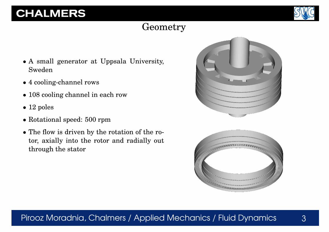
Geometry
• A small generator at Uppsala University,
Sweden
• 4 cooling-channel rows
• 108 cooling channel in each row
• 12 poles
• Rotational speed: 500 rpm
• The flow is driven by the rotation of the ro-
tor, axially into the rotor and radially out
through the stator
Pirooz Moradnia, Chalmers / Applied Mechanics / Fluid Dynamics 4
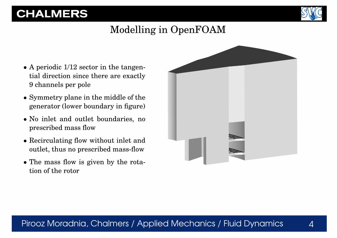
Modelling in OpenFOAM
• A periodic 1/12 sector in the tangen-
tial direction since there are exactly
9 channels per pole
• Symmetry plane in the middle of the
generator (lower boundary in figure)
• No inlet and outlet boundaries, no
prescribed mass flow
• Recirculating flow without inlet and
outlet, thus no prescribed mass-flow
• The mass flow is given by the rota-
tion of the rotor

Pirooz Moradnia, Chalmers / Applied Mechanics / Fluid Dynamics 5
Stator cooling channels
The rotor rotates clockwise. The channel numbers will be shown again in the results section
Pirooz Moradnia, Chalmers / Applied Mechanics / Fluid Dynamics 6
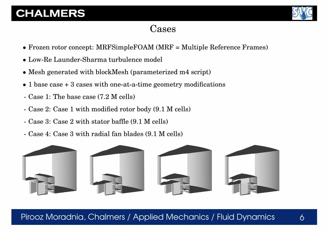
Cases
• Frozen rotor concept: MRFSimpleFOAM (MRF = Multiple Reference Frames)
• Low-Re Launder-Sharma turbulence model
• Mesh generated with blockMesh (parameterized m4 script)
• 1 base case + 3 cases with one-at-a-time geometry modifications
- Case 1: The base case (7.2 M cells)
- Case 2: Case 1 with modified rotor body (9.1 M cells)
- Case 3: Case 2 with stator baffle (9.1 M cells)
- Case 4: Case 3 with radial fan blades (9.1 M cells)
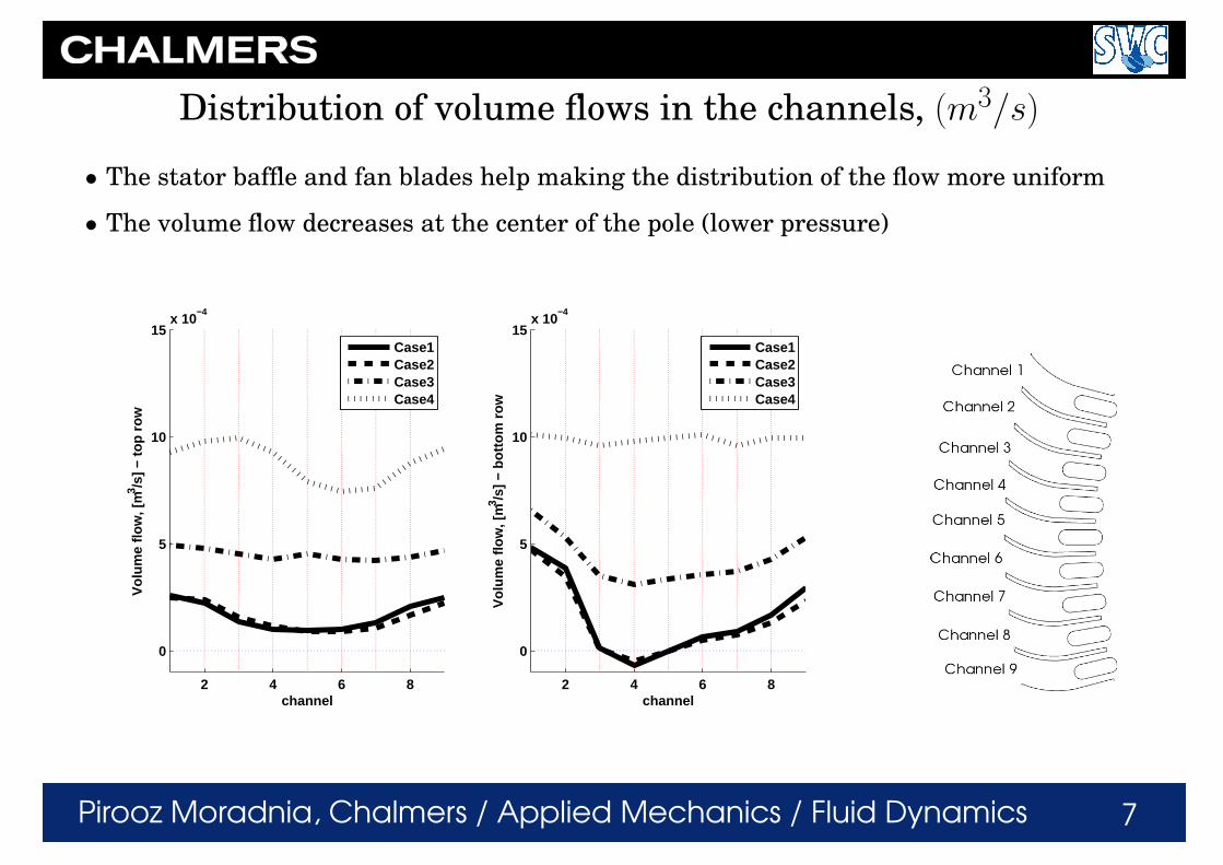
Pirooz Moradnia, Chalmers / Applied Mechanics / Fluid Dynamics 7
Distribution of volume flows in the channels, (m3/s)
• The stator baffle and fan blades help making the distribution of the flow more uniform
• The volume flow decreases at the center of the pole (lower pressure)
2 4 6 8
0
5
10
15x 10
−4
channel
Vol
ume
flow
, [m
3 /s] −
top
row
Case1Case2Case3Case4
2 4 6 8
0
5
10
15x 10
−4
channel
Vol
ume
flow
, [m
3 /s] −
bot
tom
row
Case1Case2Case3Case4
Pirooz Moradnia, Chalmers / Applied Mechanics / Fluid Dynamics 8
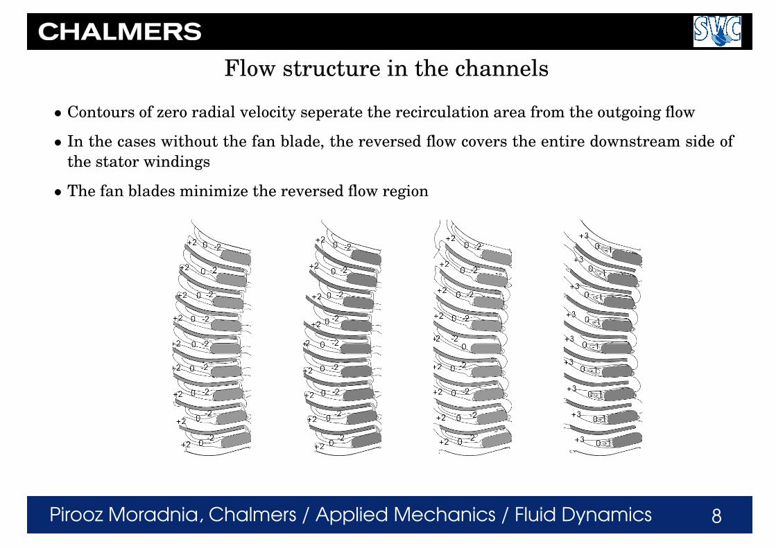
Flow structure in the channels
• Contours of zero radial velocity seperate the recirculation area from the outgoing flow
• In the cases without the fan blade, the reversed flow covers the entire downstream side of
the stator windings
• The fan blades minimize the reversed flow region

Pirooz Moradnia, Chalmers / Applied Mechanics / Fluid Dynamics 9
Unit vectors of meridional flow
• Regions with upward velocity near the stator inner
wall
• Higher pressure make-up by the stator baffle and ro-
tor fan blades give more downward flow
• Separation just at the inlet in cases with stator baffle
(less powerful separation with fan blades)
• Purely inward flow at the inlet to the stator baffle

Pirooz Moradnia, Chalmers / Applied Mechanics / Fluid Dynamics 10
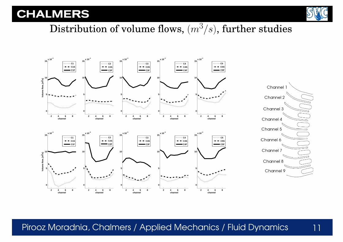
Further parametric studies
Rotor design C1 Rotor design C2 Rotor design C3 Rotor design C4 Rotor design C5
Base
Baffle
Blade
Pirooz Moradnia, Chalmers / Applied Mechanics / Fluid Dynamics 11
Distribution of volume flows, (m3/s), further studies
2 4 6 8
0
5
10
15x 10
−4
channel
Vol
ume
flow
, [m
3 /s]
C1
C1S
C1F
2 4 6 8
0
5
10
15x 10
−4
channel
C2
C2S
C2F
2 4 6 8
0
5
10
15x 10
−4
channel
C3
C3S
C3F
2 4 6 8
0
5
10
15x 10
−4
channel
C4
C4S
C4F
2 4 6 8
0
5
10
15x 10
−4
channel
C5
C5S
C5F
2 4 6 8
0
5
10
15x 10
−4
channel
Vol
ume
flow
, [m
3 /s]
C1
C1S
C1F
2 4 6 8
0
5
10
15x 10
−4
channel
C2
C2S
C2F
2 4 6 8
0
5
10
15x 10
−4
channel
C3
C3S
C3F
2 4 6 8
0
5
10
15x 10
−4
channel
C4
C4S
C4F
2 4 6 8
0
5
10
15x 10
−4
channel
C5
C5S
C5F

Pirooz Moradnia, Chalmers / Applied Mechanics / Fluid Dynamics 12
Validation cases
• Two well-known test cases - backward
facing step and Couette flow
• Comparisons with experiments and
theory
• Backward Facing step: A detailed
study of turbulence models in Open-
FOAM, led to the selection of the
Launder-Sharma turbulence model
• Laminar Couette flow, to verify the
pressure and velocity distributions
0 5 10 150
1
2
3
(x/H)
(y/H
)
U/Ucl
high−Re k−ε turbulence models
Experimentstandard k−εrealizable k−εRNG k−εNon Linear Shih k−εLien Cubic k−ε
0 5 10 150
1
2
3
(x/H)
(y/H
)
U/Ucl
low−Re k−ε turbulence models
ExperimentLam−Bremhorst k−εLaunder−Sharma k−ε
0 5 10 150
1
2
3
(x/H)
(y/H
)
U/Ucl
other turbulence models
ExperimentLRRLaunder−Gibson RSTMSpalart−Almarask−ω SST
0.37 0.375 0.38 0.385 0.39 0.395 0.4 0.4050
0.05
0.1
0.15
0.2
0.25
0.3
0.35
0.4
radius (m)
Pressure (Pa)
TheoryComputaions
0.37 0.375 0.38 0.385 0.39 0.395 0.4 0.4050
0.5
1
1.5
2
2.5
3
3.5
4
radius (m)
Velocity (m/s)
TheoryComputations
Pirooz Moradnia, Chalmers / Applied Mechanics / Fluid Dynamics 13
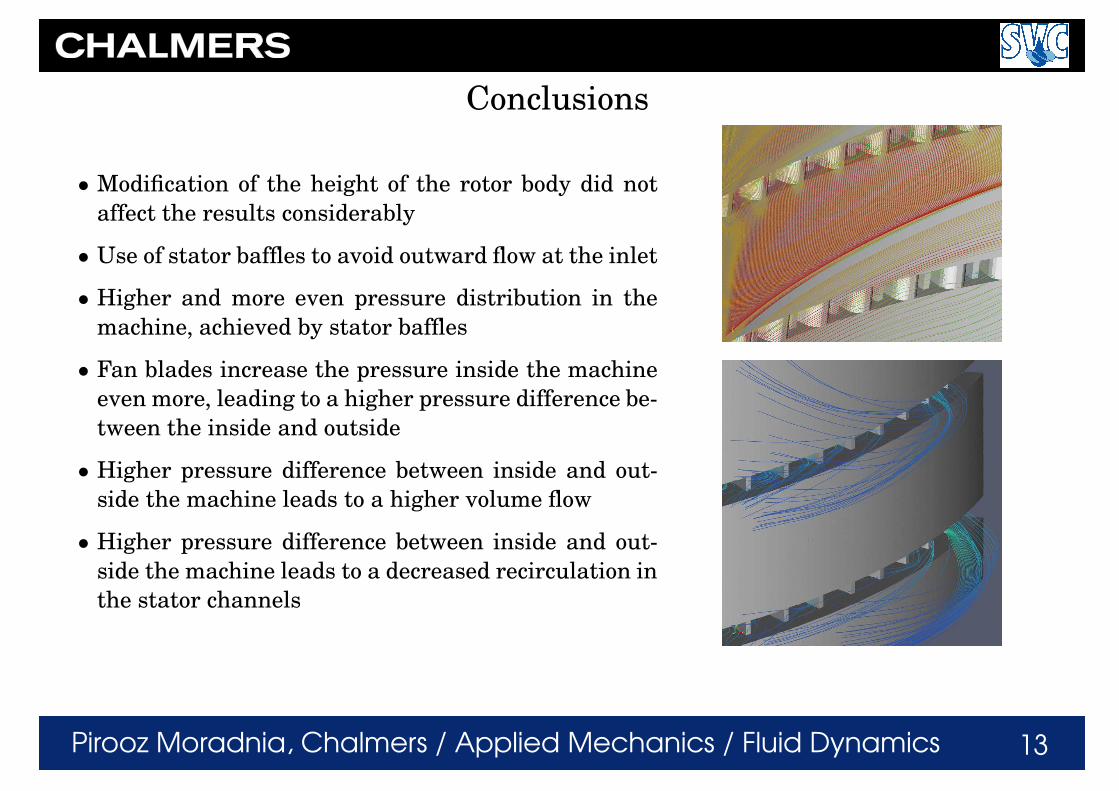
Conclusions
• Modification of the height of the rotor body did not
affect the results considerably
• Use of stator baffles to avoid outward flow at the inlet
• Higher and more even pressure distribution in the
machine, achieved by stator baffles
• Fan blades increase the pressure inside the machine
even more, leading to a higher pressure difference be-
tween the inside and outside
• Higher pressure difference between inside and out-
side the machine leads to a higher volume flow
• Higher pressure difference between inside and out-
side the machine leads to a decreased recirculation in
the stator channels
Pirooz Moradnia, Chalmers / Applied Mechanics / Fluid Dynamics 14
Thank you!
Acknowledgements
The work has been financed by SVC (www.svc.nu):
Swedish Energy Agency, ELFORSK, Svenska Kraftnat, 1
Chalmers, LTU, KTH, UU
SNIC (Swedish National Infrastructure for Computing) and C3SE (Chalmers Centre for Com-
putational Science and Engineering) have provided the computational resources.
1Companies involved: CarlBro, E.ON Vattenkraft Sverige, Fortum Generation, Jamtkraft, Jonkoping Energi, Malarenergi, Skelleftea Kraft, Sollefteaforsens,
Statoil Lubricants, Sweco VBB, Sweco Energuide, SweMin, Tekniska Verken i Linkoping, Vattenfall Research and Development, Vattenfall Vattenkraft, VG Power,
Oresundskraft, Waplans and Andritz Inepar Hydro