Embed Size (px)
Citation preview

CFD Modeling to Optimize Hydraulic Design of
River Intake Pump Station, LOTWP
Liaqat Khan, Steven Kwan, and Thomas Demlow, NHC
Patrick Van Duser, Black & Veatch
Joel Komarek, LOTWP
June 1, 2016
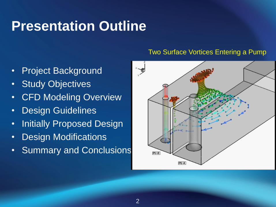
Presentation Outline
• Project Background
• Study Objectives
• CFD Modeling Overview
• Design Guidelines
• Initially Proposed Design
• Design Modifications
• Summary and Conclusions
2
Two Surface Vortices Entering a Pump

Project Background
3
• LOTWP is a partnership
between Cities of Lake
Oswego and Tigard
• LOTWP program will
upgrade to 38 mgd
• Key elements are1) River Intake Pump Station
(RIPS)
2) Raw Water Pipeline (RWP)
to transport water to the WTP
3) WTP in West Linn
4) Finish Water Pipeline (FWP)
to distribution
5) Waluga Reservoir 2 (WR2) to
store water
6) Bonita Pump Station (BPS)
to Tigard service zones River Intake Pump Station withdraws water from
the Clackamas River
Six Key Elements
1
2
3
4
56

Hydraulic Design Considerations
• Operational problems– Excessive noise
– Reduced performance
– Air binding
– Loss of prime
– Component failure
– Cavitation damage
• Causes of problems– Non-uniform velocity
– Excessive turbulence
– Vortices
– Pre-swirl
4
Damaged Pumps

Hydraulic Design Guidelines
• HI(2012) guidelines – Mean pre-swirl less than 5o
– Velocity uniform to 10% of the
mean
– No strong surface and subsurface
vortices
5
Vortex Classification

CFD Modeling
• Solves fundamental equations of fluid
flow by numerical algorithms
– Navier-Stokes equations
– Turbulence closure equations
• Divides the computational domain
into a large number of small cells
• Simultaneous solution at each node
provides a complete picture of the
hydraulic regime
• CFD software package: STAR-CCM+
6

Initial Design
• Project features
– 38-mgd capacity
– 41-foot long and 21-foot wide
– 4 operating and 1 standby
pumps
– Three screened inlet with T-
screens
• CFD model
– Mesh consists of 2.5 million
polyhedral cells
– High resolution mesh around
• pump bells and gates
– 38 mgd flow equally divided
among three gates
7
Model D
om
ain
Com
puta
tional M
esh

Initial Design: 3-D Circulation
• Higher velocity near
– Gates
– Pumps
• Several eddies are
visible
• No strong surface
vortices
8

Initial Design: Velocity Distributions
9
Ho
rizo
nta
l S
ectio
nV
ert
ica
l S
ectio
n

Initial Design: Pump Bell Hydraulics
• Eight points in each pump
bell throat
• Streamlines indicate flow
rotation or pre-swirl
• Pre-swirl varies from 4 to 12o
• Pre-swirl exceeds HI
criterion (5o) at thee pumps
• Velocities at eight points are
within with 10% of the
average
10
Pump station hydraulics do not
comply with the HI guidelines

Design Alternatives: Options 1 & 2
11
Option 1: Columns, Splitters & Fillets Option 2: Vane/Grating Basket
Pump bay width reduced to twice the bell inlet diameter

Options 1 & 2: Velocity Distributions
12
Op
tio
n1
: C
olu
mn
s,
Split
ters
& F
illets
Op
tio
n 2
: V
an
e/
Gra
ting B
asket
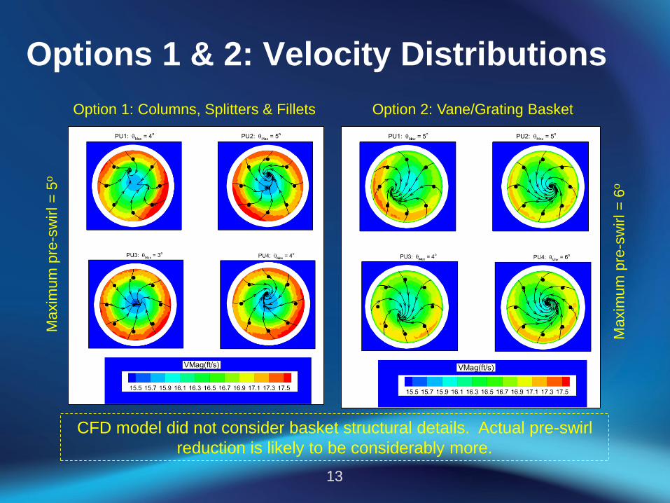
Options 1 & 2: Velocity Distributions
13
Option 1: Columns, Splitters & Fillets Option 2: Vane/Grating Basket
CFD model did not consider basket structural details. Actual pre-swirl
reduction is likely to be considerably more.
Ma
xim
um
pre
-sw
irl =
5o
Maxim
um
pre
-sw
irl =
6o

Options 1 & 2: 3-D Circulation
14
Option 1 Option 2
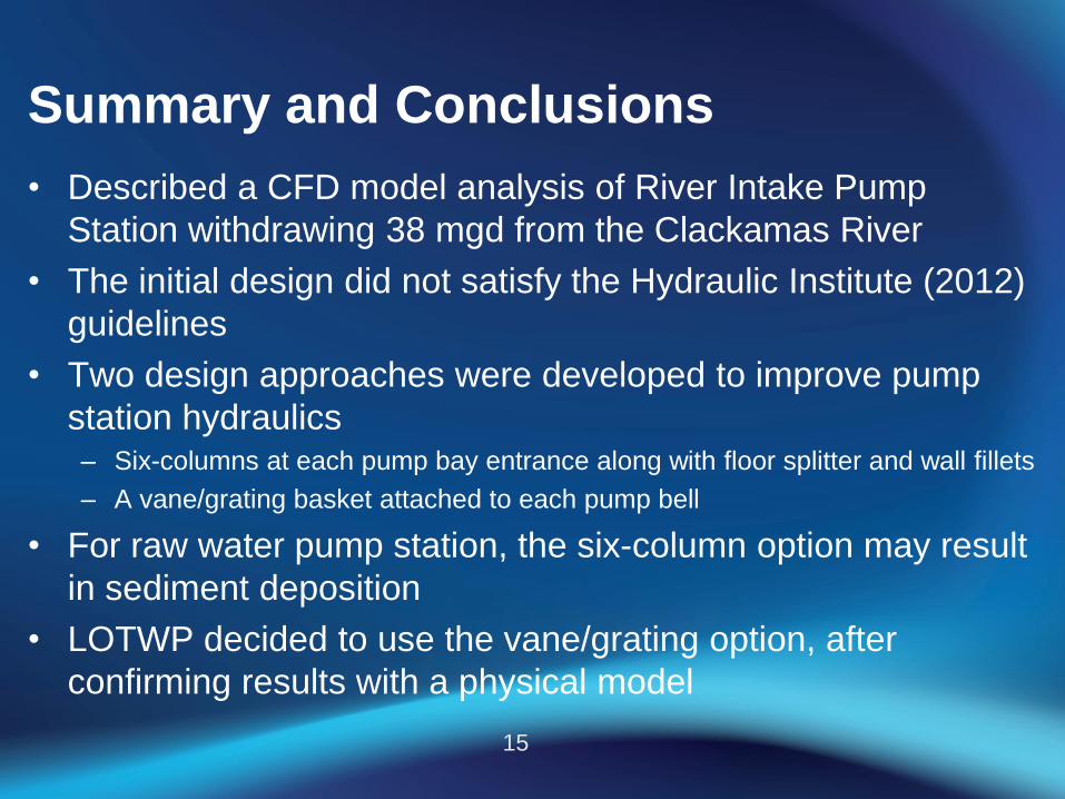
Summary and Conclusions
• Described a CFD model analysis of River Intake Pump
Station withdrawing 38 mgd from the Clackamas River
• The initial design did not satisfy the Hydraulic Institute (2012)
guidelines
• Two design approaches were developed to improve pump
station hydraulics – Six-columns at each pump bay entrance along with floor splitter and wall fillets
– A vane/grating basket attached to each pump bell
• For raw water pump station, the six-column option may result
in sediment deposition
• LOTWP decided to use the vane/grating option, after
confirming results with a physical model
15