Embed Size (px)
Citation preview
8/10/2019 CFD Exhaust jet wake and thrust characteristics of several nozzles designed for vtol downwash supresion nasa report.pdf
http://slidepdf.com/reader/full/cfd-exhaust-jet-wake-and-thrust-characteristics-of-several-nozzles-designed 1/100
C O N T R A C T O R
R E P O R T
JET
WAKE AND
VERAL NOZZLES DESIGNED
VTOL DOW NWASH SUPPRESSION
I N A N D
OUT
OF GROUND EFFECT
7 0 F AND
1200
F
NOZZLE
C.C. Higgins
D, P .
Kelly and T, W. Wainwright
E R O N A U T I C S N D P A C E D M I N I S T R A T I O N - W A S H I N G T O N ,D .C . -
JAN U%l? 'Y 1 9 6 6

8/10/2019 CFD Exhaust jet wake and thrust characteristics of several nozzles designed for vtol downwash supresion nasa report.pdf
http://slidepdf.com/reader/full/cfd-exhaust-jet-wake-and-thrust-characteristics-of-several-nozzles-designed 2/100
TECH
LIBRARY
KAFB. N Y
EXHAUST J E T WAKE AND THRUST CHARACTERISTICS OF SEVERAL
NOZZLES DESIGNED
FOR
VTOL DOWNWASH SUPPRESSION
TESTS
IN
AND OUT
OF
GROUND E FF E C T WITH
70' F
AND
1200' F
NOZZLE DISCHARGE TEMPERATURES
By C.C.Higgins, D. P. Kelly,andT. W. Wainwright
Distribution
of
t h i s repor t is provided in the interest
of
informationexchange.Responsibil i ty or hecontents
re s ides in the author or organizat ion that prepared
it.
Prepared under Contract
No .
NASw-908
by
THE BOEING COMPANY
Renton,Wash.
for
NA TIONA L A ERONAUTICS AND SPACE ADMINISTRATION
F o r s a l e b y t h e C i e o r i n g h o u s e o r F e d e r al S c i e n t i f i c an d Te c h n i c a l n f o r m a t i o n
S p r i n g f i e l d , V i r g i n i a 22151
-
P r i c e $3.00

8/10/2019 CFD Exhaust jet wake and thrust characteristics of several nozzles designed for vtol downwash supresion nasa report.pdf
http://slidepdf.com/reader/full/cfd-exhaust-jet-wake-and-thrust-characteristics-of-several-nozzles-designed 3/100
. . -
- . . .
.

8/10/2019 CFD Exhaust jet wake and thrust characteristics of several nozzles designed for vtol downwash supresion nasa report.pdf
http://slidepdf.com/reader/full/cfd-exhaust-jet-wake-and-thrust-characteristics-of-several-nozzles-designed 4/100
EXHAUST J E T WAKE AND THRUST CHARACTERISTICS OF SEVERAL
NOZZLES DESIGNED FOR VTOL DOWNWASH SUPPRESSION- TESTS
IN
AND OUT OF GROUND EF FECT WITH 7 0 ° F AND 1200°F NOZZLE
DISCHARGE TEMPERATURES
By
C.C.
Higgins, D.
P.
Kelly,and T. W. Wainwright
SUMMARY
The jet wake degradatio n and thrust character istics of eleven exhaust
nozzle models designed for dynamic pressure and temperature reduction in the
jet were evaluated statically, using both hot gases and unheated air, and similar
tests were conducted with
a
reference circular nozzle. Addition al tests of
selected nozzles were co nducted to determ ine effec ts of fuselage and/or proximity
of a ground plane upon thrust and jet wake character is tics .
Results show significant jet wake degradation for all suppressor nozzles
tested, both in and out of ground effect and with various fuselage configurations.
Most rapid
jet
wake degradation was achieved with nozzle designs having widely
spaced and/or high aspect ratio nozzle elements. Except for regions very
close to the nozzle exit , increasing exit wall divergence angles provided only a
small improvement in jet wake degradation characteristics.
Thrus t losses were a function of no zzle geo metry, w ith losses m inimized
for nozzle s having sm all exit wall dive rgence an gles and m oderate va lues of
aspe ct ra tio of the discharge openings. The effect upon thr us t of varying spacing
between nozzle elements was not clearly established by these tests. Combining
the nozzles with a fuselage resulted in additional thrust losses ; these losses
further increase d when operating in proximity with a ground surface. Ventila-
tion of the fuselage reduc ed thrust losses, partic ularly with suppre ssor nozzles ,
but all nozzle and fuselage configurations exhibited large los ses when tested in
proximity to a ground surface. These thrust losses were associated with the
large projected fuselage area used in the present tests, and it
is
concluded
that the projected area must be minimized i f excess ive losses are to be avoided
during operation in ground effect.

8/10/2019 CFD Exhaust jet wake and thrust characteristics of several nozzles designed for vtol downwash supresion nasa report.pdf
http://slidepdf.com/reader/full/cfd-exhaust-jet-wake-and-thrust-characteristics-of-several-nozzles-designed 5/100
I
I
. .
_.
. . ..
INTRODUCTION
Ground impingement of the downwash from VTO L aircraft can produce
ope rati ona l problem s of varying degree , depending upon the type of landing
site
and the disc-loading of the
lift
system. With
jet
powered VTOL
aircraft
built
to date, operations have been conducted primarily from prepared sites, thereby
avoiding problems of surface deterior ation from imping ement of high velocity,
high temperature exhaust gases on unp rotected natural surfaces. Some success
has been achieved with operational techniques which reduce exposure time of'the
surfaces to jet impingement, and ways of rapidly preparing the sites with surface
coatings
are
being investigated. Other solutions to the jet impingement problem
have been proposed, but no solution appears to be completely satisfactor y at
this time . Many of the proposed solution s involve some operat ional o r logistic
penalties, and other approaches to the problem must be investigated if VTOL
aircraft are to achiev e maxim um utilization . In practice, a combination of the
best elements of a number of so lutions may be required to achieve the desired
operational capability.
In an effort to reduce the severity of the fundamental problem, particularly
with jet-lift
aircraft
with high disc loadings,
a
program to evaluate various ex-
haust nozzle design factors which could lead to a reduction
of
dynamic pressures
and temperatures
at
the ground surface was undertaken (reference
1).
The
current ef for t represents a follow-on to the program reported in re fer ence
1;
emphasis in the current tests was directed toward an evaluation of the nozzle
performance and
jet
wake degradation characteristics of suppressor nozzle de-
signs under representat ive jet engine nozzle discharge temperatures and
pres-
sure s. Effe cts of
a
simulate d fuselage upon instal led nozzle perform ance,
together with the effects of an adjace nt groun d plane, were evalua ted. Significant
thrust lo sses d ue to advers e press ure field s indu ced on the undersurface of the
fuselage
(i .
e.
,
suck-down losses) have been reporte d by other investigato rs,
references 2 , 3 , and
4 ,
and it was anticipa ted that the higher rates of mixing
associated with suppressor nozzles would result in proportio nately larger
t h r u s t
losses .
Twelve nozzle configurations were evaluated in the current tests, designated
as
Phase I1 tests to distinguish the present efforts from those reported in
reference
1 ,
which
are
designated
as
Phase I
tests.
Of the twelve nozzle con-
figuratio ns tested, three nozzle s duplica ted Nozzles No. 1 , No. 8, and No. 12
of
the Phase
I tests.
Nine additional nozzles, each with four parallel rectangular
discha rge ports, were design ed to investig ate in greater detail the range of
nozzle design param eters applica ble to VTOL
jet
lift
aircraft.
The principal
design parameters were:
1) spacingbetweennozzleelements
2) internalexitwalldivergenceangle
3) asp ect ratio of the elemen ts forming the nozzle exit
2

8/10/2019 CFD Exhaust jet wake and thrust characteristics of several nozzles designed for vtol downwash supresion nasa report.pdf
http://slidepdf.com/reader/full/cfd-exhaust-jet-wake-and-thrust-characteristics-of-several-nozzles-designed 6/100
All nozzle designs were evaluated without fuselage o r ground plane at
both
70°F
and
1 2 0 0 ° F
nozzle discharge temperatures. Surveys of the pres sure s
and tempera tures in the jet wake of each nozzle were made at a nozzle pressure
ra ti o of 2 . 0 , while thrust measurements were made over
a
range of nozzle
pressure r a t ios f rom 1. 3 to 2 .5 . Following these tests, the thrust and jet wake
degrada tion chara cteristics of the circular n ozzle and
two
suppressor nozzles
were evaluated with
a
large simulated fuselage outof ground
effect
in which
vary ing d egre es of fuselage ventilation were provided. Testing was completed
with these three nozzles and various fuselage configurat ions while operat ingt
a distance of five equivalent nozzle diameters from
a
ground plane. Thrust
measure ments and survey s of jet wake pressures and temperatures in the
efflux
ove r the surf ace of the ground plane were obtained in these
tests.
Except for
differen ces of proced ure and eq uipmen t necessita ted by the tes ts at 1200 F ex-
haust gas t emperatures , the cur rent tests were conducted in
a
manner s imi lar
to those of the Pha se
I
tests.
This rese arch was spo nso red by the National Aeronautics and Space
Administration through the Office of G rants and Re search Co ntracts und er
Contract NASw-9d8.
SYMBOLS
CF
cP
L
W
exit area of the nozzle, square inche s
projected
area
of the fuselage on the ground plane, square
inches
aspect
ratio, D /Area o r length/width
m as s flow coefficien t, actual mass flow/ide al mass flow
stat ic pressure coeff icient ,
's
measured
-
PJPt
-Po
n
effective velocity coefficient, effective exit velocity/ideal
exit velocity. Effective velocity
=
(thrust/mass flow)actual
incremental change of effective velocity coefficient
dia me ter of nozzle exit, inches
di am ete r of
a
circular nozzle with
exit
area
equal to that
of
a
non-circular nozzle, inches
length of an element of rectangular exit planform, inches
width of an element of rectang ular exit planform, inches
3

8/10/2019 CFD Exhaust jet wake and thrust characteristics of several nozzles designed for vtol downwash supresion nasa report.pdf
http://slidepdf.com/reader/full/cfd-exhaust-jet-wake-and-thrust-characteristics-of-several-nozzles-designed 7/100
R
radialis tanceromen ter of groundlane,nches
S distanceetweenente rlines of nozzlelements,nches
X f
Y f z axes of a righthandcoordinatesystemwith he Z axis n
the dire ction of flow. Also designat es distance s along
each re spe ctiv e axis from c ente r of nozzle exit, inches
distance from core
o r
apparent core to any point in the
mixing region, measured parallel to the
X
axis, inches
(ref. f igure 29).
x 25, distanceromore o r apparentore oeferenceontour
m a x
at twenty-five
pe r
cent ynamic ressure,nches
(ref.
f igure 29).
x SOT, distancerom ore r apparent ore oeference ontour
m a x
at fifty
pe r
centdifferentialemperatures,nches (ref. figure
2 9,
by analogy).
Y
distance from core or apparen t core to any point in the
mixing region, measured parallel to the Y axis, inches
(ref. figure 29).
y 254, distancerom ore
o r
apparent ore oeference ontour
m a x at
twenty-five
per
cent ynamic ressure,nches (ref.
f igure 29).
Y.50T, distanceromore o r apparentore oeferenceontour
m a x at
fiftyper entdifferential emperatures,nches
(ref.
figure
29,
by
analogy).
h
n
P o
p s f
p s g
height above the ground plane, inches
distance from ground plane to the end of the jet core, inches
load induced on plate , lb .
number of exit segmen ts
a tmospher ic pressure , Ibs / sq f t
stati c pres sure m easu red by orifices in the fuselage surface,
lbs/sq f t
stati c p ress ure mea sure d by orifices in the ground plane,
lbs/sq f t
4

8/10/2019 CFD Exhaust jet wake and thrust characteristics of several nozzles designed for vtol downwash supresion nasa report.pdf
http://slidepdf.com/reader/full/cfd-exhaust-jet-wake-and-thrust-characteristics-of-several-nozzles-designed 8/100
P t
9
m a x
' g m a x
qgS
rnax
static pressure at any specified point in the
jet
wake,
lbs/sq f t
total or stagnation pressure, lbs/sq
f t
total
o r
stagnation pressure
at
the nozzle exit , lbs/sq
f t
total o r stagnat ion pressure at any specified point in the
jet
wake, lbs/sq f t
F
total o r s tagnat ion pressure
at
any specified point on, or
over the ground plane, lbs/sq f t
compressible dynamic pressure at the nozzle exit, p
-
po,
lbs/sq f t tn
compressible dynamic pressure
at
any specified point in the
jet
wake,p - pot bs/sq t
t Z
maximum compressible dynamic pressure measured at any
specified transverse plane perpendicular to the Z axis,
Pt
- po, lbs/sq f t
%ax
compressible dynamic pressure
at
any specified point on, o r
adjacent o, he ground plane, pt -
po,
Ibs/sq f t
.gr
maximum compressible dynamic pressure measured on,
o r
adjacent to, the ground plane at specified distances of the
ground laneromhe ozzle, p
-
po, lbs/sq f t
tgr
max
local dynamic pressure measured on, o r adjacent to the
ground plane p
maximum local dynamic pressure measured on, or adjacent
toheroundlane
,
lb/sq
f t
T
5
jet thrust , lbs

8/10/2019 CFD Exhaust jet wake and thrust characteristics of several nozzles designed for vtol downwash supresion nasa report.pdf
http://slidepdf.com/reader/full/cfd-exhaust-jet-wake-and-thrust-characteristics-of-several-nozzles-designed 9/100
+ t
g l m a x
g'rnax
t t
t t
n
Z
t t
Z
ma x
Z
C
r
Tg rnax
tZ
rnax
e
6
ambient emperature,
F
total
or
stagnat ion temperature , F
total temperature measured in the boundary layer
immediately adjacent to the ground plane, O F
maximum total temperature measured in the boundary
layer immediately adjacent to the ground plane,
O F
total temperature measured in the
jet efflux
over the
ground plane, O F
maximum total temperature measured in the
jet
efflux over
the ground plane,
O F
total temperature at nozzle exit ,
O F
total temperature measured
at
any specified point in the
jet wake, O F
maximum total temperature measured
at
any t ransverse
plane perpendicular to the Z axis , O F
length of unmixed jet core, measured from nozzle exi t ,
inches
nozzle wall divergence angle, referred to the longitudinal
axis of th e nozzle, degrees
nozzle wall convergence angle, referred to the longitudinal
axis of. the nozzle, degrees
differential temperature at any specified point on,
o r
adjacent o, he'groundplane
it - - t
o r
tt - to, F
gl
0
g r
maximum differential temperature at any specified point on, o r
adjacent o, hegroundplane
t
-
t o r tt - to,
O F
g1maxrmax
t
0
differential temperature
at
the nozzle exit ,
tt -
to,
F
n
differential temperature
at
any specified point in the
jet
wake,
tt
-
to,
F
Z
maximum differential temperature measured
at
any specified
transverseplaneperpendicular o he Z axis ,
tt - to, F
angle subtended by a nozzle sector , degrees
Z
max

8/10/2019 CFD Exhaust jet wake and thrust characteristics of several nozzles designed for vtol downwash supresion nasa report.pdf
http://slidepdf.com/reader/full/cfd-exhaust-jet-wake-and-thrust-characteristics-of-several-nozzles-designed 10/100
A P P A R A T U S A N D P R O C E D U R E
Models
The nozzle models used in this program are described in figures 1
through
4
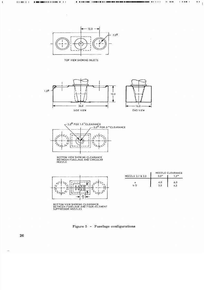
while figure
5
give s deta ils of the fuselage configurations used with
nozzles 1 . 1 , 2.1,
2. 5 ,
2.6, and 2.8. The circular and twelve segment nozzles
shown in figure
1
were the same nozzles (designated
as
nozzles Nos.
1
and
1 2
during the Phase
I
tests, reference 1)previously tested, while the delta nozzle
shown in figure 1 was a new nozzle of sta inless steel whic h duplicate d the
conto urs of the previous fiberglas s delta nozzle.
The circular nozzle provided
a
reference standard to which the perform-
anc e of the remaining nozzles could be compared, while the delta and twelve
segment nozzles provided correlation with previou's Phase I tests
at
lower
pressure s and tempera tures. Basic characte r is t ics of these nozzles
are
shown
in
Nozzle No. Configuration
1. 1
1 . 2
1. 3
Circular Nozzle
DeltaNozzle
A3
= 5
,
0
=
5
Twelve Segment Suppressor Nozzle,
8
=
6
The additional nine nozzles
shown
in figure
2
consiste d of four rectangular
discharge elements w hich were designed to cover the probable range of nozzle
geometry applicable to
jet-lift VTOL
aircraf t . Nozzle design parameters for
the four-element suppressor nozzles were (1) nozzle internal wall divergence
angle,
0
; (2) spacing
to
width ratio
of
the nozzle elements,
S/W;
and
(3 )
aspect
ratio of thenozzleelement, . Thedimensions of the our-ele mentsuppressor
nozzles
2 . 1
through 2.9,
are
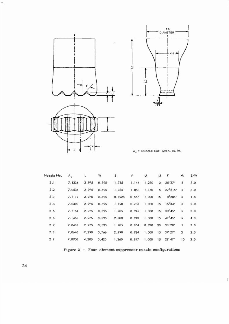
shown in figure 3. Configurations were selected
so that a systema tic v ariation of each of the n ozzle design parame ters w as
obtained for
at least
three nozzles. The nozzles selected
are
shown in the
following table:
7

8/10/2019 CFD Exhaust jet wake and thrust characteristics of several nozzles designed for vtol downwash supresion nasa report.pdf
http://slidepdf.com/reader/full/cfd-exhaust-jet-wake-and-thrust-characteristics-of-several-nozzles-designed 11/100
Nozzle Bo. Variablenvestigatedariableseldonstant
2 . 1
2 . 2
2 . 5
2 . 7
2 . 3
2 . 4
2 . 5
2 . 6
2 . 8
2. 5
2.9
(3
=
0
to
30
s /w= 1 . 5 to 4.0
A3 =
3 . 0
to 10. 0
m = 5 . 0
s/w= 3 . 0
Ai
= 5 . 0
p = 15
S/W
=
3 . 0
(3
=
1 5
All nozzles were designed to have the same physical exit area as that of
the three-inch-diameter circular nozzle. The four-element suppressor nozzles
were designed with internal contours which provided similar cross-sectional
area distributions as shown in figure 4. A l l nozzles, except Nos. 1.1 and 1 .3 ,
were fabri cate d of stainless steel for dimensional stability at the
1 2 0 0 ° F
exhaust
gas temperatures. Circular nozzle No. 1. 1 was fabricated with thick walls of
mild steel, and distortion did not appear to be a problem. However, thermal
distortion and failure of a weld occurred with the twelve segment nozzle, and
only
a
limited number of tests we re conducted.
The fuselage incorporated large orifices on the Ifupper side of the fuselage
which would permit ambient air to flow from the upp er fuselage s urface into th e
fuselage cavity; for some of the tests these orifices were covered with solid
plates to prevent the flow of ventilating
air
through the fuselage. The lower
sur fac e of the fuselage also incorporated removable plates which permitted
varia tion in the clearance between the nozzle and the lower surface of the
fuselage. With these plates, clearances of 0 0 . 5 , and 1.
5
inches were tested
with circular nozzle 1.1 and suppressor nozzles 2 . 1 and
2.5.
Combining varia-
tion of lower fuselage cleara nce space with up per fuselage ven tilation opening s
provided six fuselage and nozzle configura tions; of these, the two extrem e con-
figurations were investigated in greatest detail; i. e. , sealed nozzle and fuselage
for minimum ventilation in one
case,
and maximum nozzle clearance with upper
fuselage open for maximum ventilation in the other
case.
The fuselage was
cons truc ted prim arily of aluminum, but the plates used to vary the clearance
between the nozzles and the lower fuselage surface were fabricated from stainless
steel. F o r the plates which reduced the clearance space between the nozzles
and fuselage to zero, a perfect seal was not achieved and spaces on the order
of
0.
02 inches existed between the nozzles and the fuselage at some points.
8

8/10/2019 CFD Exhaust jet wake and thrust characteristics of several nozzles designed for vtol downwash supresion nasa report.pdf
http://slidepdf.com/reader/full/cfd-exhaust-jet-wake-and-thrust-characteristics-of-several-nozzles-designed 12/100
Nozzle Test Rig
A schematic of the
test
faci lity is shown in fig ure 6. Additional details of
the instrumentation are shown in figure 7, and photographs of the rig and
in-
strumentation
are
shown in figure 8.
A s
in the Phase
I
tests,
the nozzle mod els were installed on
a
bellmouth
transition section
at
the end of a twenty-inch inside diameter plenum chamber.
Three internal baffle plates and a sc reen were used to provide unifo rm flow at
the entrance to the bellmou th section. The plenum was suspended by mea ns of
four flexures which minimized resistance to fore and aft movement. Thrust
loads were balanced only by the strain -gaged thrust rin g and a small force
resulting from deflection of the flexible inlet air pipe. Direct calibration of the
installed strain-gage d thrust ring by means of dead weights effectively isolated
nozzle th rust force s from a ny mec hanical lo ads imp osed y the inlet air pipe
and other service connections.
Airflow was measu red with an ASME l ong r adiu s flow noz zle upstre am of
the air preheater , and
a
dual valve arrangem ent permitted a constant Mach
number to be maintained through the flow nozzle . Filte red air for the noz zle
tests was obtained from a laboratory supply system at approximately
70
F with
a dew point of -40°F or less. For hot gas testing a propane-fired preheater was
installed upstream of the plenum chamber.
Pressure measurements in the jet wake were obtained with a remotely-
controlled Pitot-static probe which could be trave rsed along ea ch coordin ate
axis
of the model . Pressures
were
sensed by mean s of tra nsdu cers . Press ures
obtained in wake surveys we re recorde d directly as a function of probe pos ition
on Moseley
X Y
plot ters; other pressure data were recorded ei ther manual ly or
automatic ally on IBM punch c ard equipm ent.
Temperature measurements in the jet wake were obtained with
a
forty-one
element chrome l-alumel thermocouple rake installed on the ma st of the probe
traversing me chanism ; the thermocoup les were of the shielded stagnation type
shown in figure
7.
For the hot gas
tests,
operating conditions were based upon
the ma xim um tem pera ture found with the forty-one element thermocouple rake
when positioned
at
the nozzle exit plane; this nozzle discharge temperature was
then maintained throughout the jet wake surveys or other tests by means of a
reference thermoco uple just upstream of the nozzle exit. For the 1 2 0 0 °F nozzle
discharge condition of the prese nt tests , the ave rage no zzle di scha rge tem pera -
tur e was found to be 1161°F.
A
thermal profile was present at the nozzle
exit,
apparently the resultof non-uniform temperature distribution generated within
the propane fired preheater.
A
24 inch by 36 inch translating ground plane
was
instrumented as shown
in figures
7
and
8
to measure pressures and temperatures
at
the surface. Pres-
sure and temperature surveys in the boundary layer above the ground plane were
obtained using traversing five-element total pressure and stagnation tempera-
tu re ra ke s of the type shown in figure
7.
Surveys along the major and minor
9

8/10/2019 CFD Exhaust jet wake and thrust characteristics of several nozzles designed for vtol downwash supresion nasa report.pdf
http://slidepdf.com/reader/full/cfd-exhaust-jet-wake-and-thrust-characteristics-of-several-nozzles-designed 13/100
axes were o btained by rotacmg the nozzles (and fuselage when used)90 degrees
at a quick-disconnect nozzle flange.
Data Accuracy
Repeated calibrations and checks on the
rig
instrumentation and read-out
equipment were made during the program, and it
is
believed that all data, with
the exception of the temperatures, were accurate within f 0.5 per cent of full
scale values. Temperatures were repeatable within
f 15 F , o r
in the
case
of
differential temperature ratios,
f 1
0 per cent. Shielded thermocouples were
used, where possible, to minimize radiation effects at the thermocouple junctions,
and it
is
believed that the accurac y of these readings was within f 2 . 0 per cent
of
f u l l
scale value
RESULTS
Method of Data Presentation
Because of uncertainties a ssociated with static pressure measurements
in an intensely turbulent stream, all dynamic pressure measurements are pre-
sented as differentials between indicated probe total pressure and atmospheric
pressure . S ta t ic pressures are presented
as
differential pressures with respect
to atmosp heric pressure s. Presentatio n of dynamic pressure data in this form
introduces effects of co mpress ibility, but the treatmen t is consistent with
.previous investigations. The use of dimensio nless ratios further minimizes
poss ible er rors due to compress ibi l ity effects. Sign conventions have been
taken
as
posi t ive for values where the measured pressure was greater than
atmospheric, and negative when the pressure was less than atmospheric.
In the c ase of dynamic p ressures d etermined w ith respect toa ground
surface, it has been found advantageous in some analy ses to use the differential
pressure between total pressure measured above the ground anda local s tat ic
pressure measured at the su rfac e of the ground plane, rather than a differential
between the total pressure above the ground plane and atmospheric. Wherever
this procedure has been followed, the resultant dynamic pressure has been d es-
ignated as a local dynamic pressure, to distinguish from dynamic pressures
referenced to atmospheric pressure. Data obtained for the tests in ground
effect
have been presented in both form s; conseq uen tly, care must be used in
making comparisons between various sections or figures of this report.
10

8/10/2019 CFD Exhaust jet wake and thrust characteristics of several nozzles designed for vtol downwash supresion nasa report.pdf
http://slidepdf.com/reader/full/cfd-exhaust-jet-wake-and-thrust-characteristics-of-several-nozzles-designed 14/100
Nozzle Performance Evaluation
Effective velocity and mass flow coefficients were determined for all
basic nozzles using unheated air;
a
typical test configuration is shown in figure
8a. Resul ts for the three Phase I nozzle configurations previously evaluated in
reference
1 a re
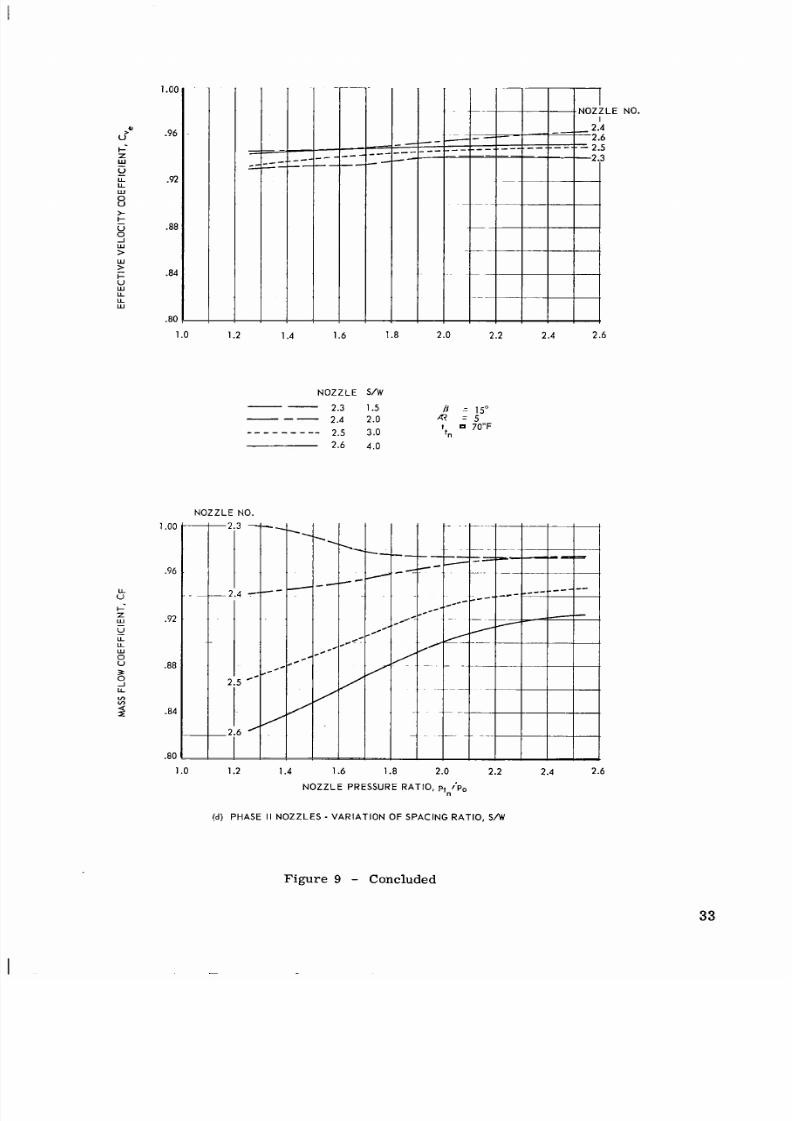
shown in figure 9a. Other results obtaine d in these tests have
been grouped according to the su ppressor no zzle design parameters of exit wall
angle
fj
aspe ct ratio of the elements A z and spacing to width ratio
S/W,
figures 9b, 9c and 9d.
It
may be seen from these resul ts that , in general , both
effective v elocitv and m ass flow coefficients incre ased with inc reasing n ozzle
pressure ratio. In genera l, effective velocity and mass flow coefficients de-
crease progressively with increasing
exit
wall angle, increasing aspect ratio of
the nozzle elements, and increasing spacing to width ratio. Howev er, the
mass
flow coefficients for nozzle 2.3 show a rev er sal of trend at low nozzle pressure
rat ios. This
effect is
believed to be related to internal flow separa tion due to
local high velocities and unfavorable pressure gradients associated with
xit wall
divergence angle fj
=
15 and the small exit
w a l l
convergence angle r
=
8.4 .
The other nozzles in this
series
(nozzle s 2.4, 2.5, and 2.6) had larger values of
exit
wall
convergence angle
r
,
thus providing more favorable pressure gradients
and lower velocities
at
any specified cross section prior to the nozzle exit .
Following evaluation of t he b asic noz zles , tests w e r e conducted with
nozzles Nos. 1. 1 , 2.
1, 2. 5 , 2.
6, and 2.
8
in conjunction with an unventilated
fuse lage , simi lar to that sho wn~ n figure 8c. The effect of a ground plane on
effective velocity and flow coefficients was evaluated in th is se ri es of test s.
Results obtained in ground effect and out of ground effect for both the basic
nozzle and the unventila ted fuselage config urations are shown in fig ure 10 for
nozzles Nos.
1. 1, 2.
1, and 2.5. These results indicate that effective velocity
coefficients were reduced by either the presenc e of
a
fuselage
o r
ground plane,
and largest reductio ns were found when the fuselage and ground plane were tested
together. These effects
are
caused by reduce d static pressures acting over the
pr oje cte d are a of the fuselage and plenu m, rather than chang es in the effective
velocity coefficient of the bas ic noz zles .
N o
significa nt effects upon m a ss flow
coefficients
were
noted for any configuration of fu selage or ground plane evalua ted
in the present program.
The effects of variation of the clearance between the nozzle exit and fuselage
lower surface upon thrust wer e evaluate d for
two
conditions of fuselage cavity
ventilation; i. e.
,
upper fuselage inlets were ei ther both open or both closed.
The resul ts for tests out of ground effect a r e shown in figure 11, while results
obtained in ground effect
are
shown in figure
12
for the circular nozzle 1. 1 and
suppressor nozzles
2 . 1
and 2.5. These results indicate that increased clearance
between the nozzle and fuselage im proves effective velocity coefficient, while
ma ss flow coefficients remain essentially unchanged in all cases . Larges t
benefits of clearance between the nozzles and fuselage were obtained with the
suppre ssor nozzles, and it was found that
a
clea ran ce of
0.5
inches
was
nearly
as
effective as a cle ara nc e of 1 .5 inches. Ventilating the fuselage cavity
re-
sult ed in only minor improvement in effective velocity coeffic ients.
1 1
8/10/2019 CFD Exhaust jet wake and thrust characteristics of several nozzles designed for vtol downwash supresion nasa report.pdf
http://slidepdf.com/reader/full/cfd-exhaust-jet-wake-and-thrust-characteristics-of-several-nozzles-designed 15/100
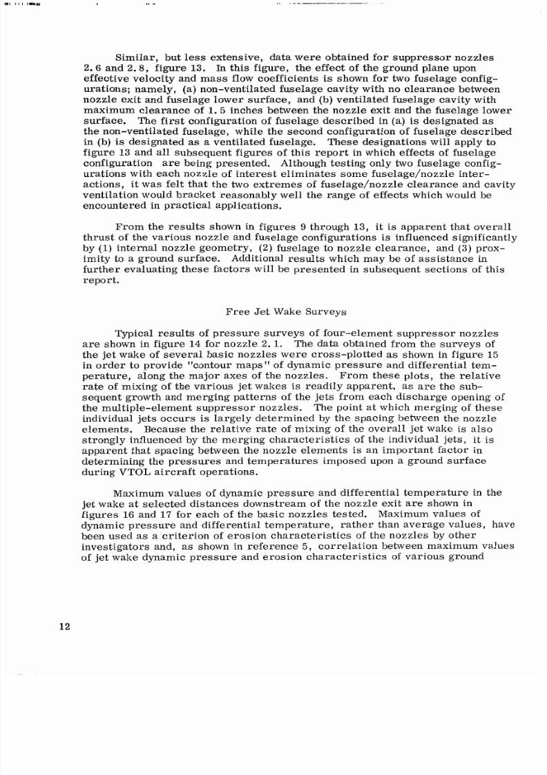
Similar, but
less
extensive, data were obtained for suppressor nozzles
2 . 6
and
2.8,
f igure 13.
In
this figure, the
effect
of the ground plane upon
effective velocity and mass flow coefficients
is
shown for two fuselage config-
urations; namely, (a)non-ventilated fuselage cavity with no clearance between
nozzle
exit
and fuselage lower surface, and (b) vent i lated fuselage cavi ty with
maximum clearance of 1 . 5 inches between the nozzle exit and the fuselage lower
surface.
The
first configuration of fuse lage described in
(a)
is
designated
as
the non-ventilated fuselage, while the second configuration of fusel age descri bed
in (b) is designated as
a
ventilated fuselage. These designations will apply to
f igure 13 and all subsequent figures of thi s re po rt in which
effects
of fuselage
configuration are being presented. Although testing only two fuselage config-
urations with each n ozzle of intere st eliminates some fus elage/noz zle inter-
actions, it was felt that the two extremes of fuselage/nozzle clearance and cavity
ventilation would bracket reasona bly well the range of
effects
which would be
encountered in practical applications.
From the results shown in figures 9 through 13, it is apparent that overall
thrust
of
the various nozzle and fuselage configurations
is
influenced significantly
by
(1)
nternal nozzle geometry,
(2 )
fuselage to nozzle clearance, and
(3)
prox-
imity to a ground surface. Additional results which may be of as si st an ce in
further evalu ating these factors will be pre sented in subsequent sections of this
report .
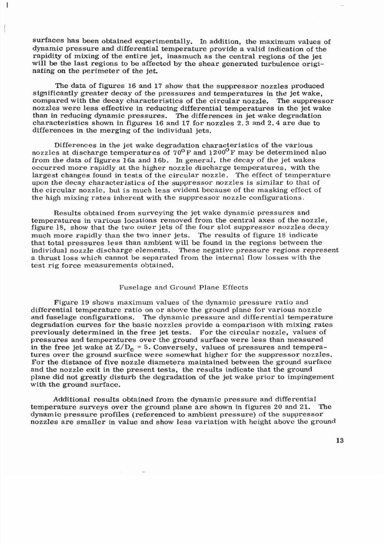
Fr ee Je t Wake Surveys
Typical results of p res sur e sur vey s of four-element suppressor nozzles
are shown in figure
14
for nozzle 2.1. The data obtained from the surveys of
the jet wake of several basic n ozzles were cro ss-plotted as shown in figure 15
in order to provide contour maps of dynamic pressure and differential tem-
perature, along the major axes of the nozzles. From these plots, the relative
rate of mixing of the va rious jet wake s is readily apparent, as are the sub-
sequent g rowth an d mergin g patterns of the jets from each discharge opening of
the multiple-e lement suppress or nozzles. The point at which merging of these
individual jets occurs is largely de termined by the spacing between the nozzle
elements. Becau se the relative rate of mixing of the ove rall jet wake is also
strongly influenced by the me rg ing char act eri sti cs of the individual jets,
it
is
apparent that spacing between the nozzle elements is an important factor in
determining the pressur es and tem peratures im posed upon a ground surface
during
VTOL
aircraft operations.
Maximum values
of
dynamic pressure and differential temperature in the
jet wake at selected dis tances do wnstream of the nozzle exit a r e shown in
figures 16 and 17 for e ach of the basic nozzles tested. Maximum values of
dynamic pressure and different ial temperature, rather than average values, have
been used as a crite rion of e rosio n char acter istic s of the nozzles by other
investigators and, as shown in reference 5, correlation between maximum values
of jet wake d ynamic pressure and e rosion c haracteristics of various ground
12
8/10/2019 CFD Exhaust jet wake and thrust characteristics of several nozzles designed for vtol downwash supresion nasa report.pdf
http://slidepdf.com/reader/full/cfd-exhaust-jet-wake-and-thrust-characteristics-of-several-nozzles-designed 16/100
surfaces has been obtained experimentally. In addition , the maximum values of
dynamic pressure and differential temperature provide a valid indication of the
rapidity of mixing of the entire jet, inasmuch
as
the ce ntra l regi ons of the jet
will be the last regions to be affected by the shear generated turbulenc e origi-
nating
on
the perimeter of the jet.
The data of figures 16 and 1 7 show that the suppressor nozzles produced
significantly
greater
decay of the pressures and temperatures in the jet wake,
compared with the decay characteris tics of the circ ular noz zle. The suppressor
nozzles
were less
effective in reduc ing differential temp eratures in the jet wake
than in reducing dynamic pressures . The differences in jet wake degradation
cha rac ter ist ics shown in figures 16 and 17 for nozzles
2 . 3
and 2.4
are
due to
diff eren ces in the mer ging of the individual
jets.
Differences in the jet wake deg-radation cha rac ter ist ics of th e vari ous
nozzles at discharge temperature s of 70°F and 1200°F may be determined also
from the data of
figures
16a and
16b.
In general, the decay of th e jet wakes
occurred more rapidly at the higher nozzle discharge temperatures , with the
largest changes found in tes ts of the circular nozzle. The effect of tem per atu re
upon the dec ay chara cteristics of the suppressor nozzles is similar to that of
the circular nozzle, but
is
much less evident beca use of the masking effec t of
the high mixing rates inherent with the suppressor nozzle configurations.
Results obtained from surveying the jet wake dynamic pressures and
tem per atu res in various locations removed from the central axes of the nozzle,
figu re 18, show that the two outer jets of the fo ur slot suppressor no zzles decay
much more rapidly than the two inner jets. The results of figure 18 indicate
that total pressures less than am bient w ill be found in the regions between the
individual nozzle discharge elements. These negative pressure regions represent
a thrust loss which can not be separate d from the internal flow losses with the
test
rig force measurements obtained.
Fuselage and
Ground Plane
Effects
Figure 1 9 shows maximum values of the dynamic pressure ratio and
differential temperature ratio on o r above the ground plane for various nozzle
and fuselage configurations. The dynamic pressure and differential temperature
degradation curves for the basic nozzles provide
a
comparison with mixing rates
previously determine d in the free jet
tests.
For the circular nozzle, values of
pressures and temperatures over the ground surface were less than measured
in the free jet wake at Z/De
= 5.
Conversely, values of pres sure s and temper a-
tures over the ground surface were somewhat higher for the suppressor nozzles.
For th e dis tance of five nozzle diameters maintained between the ground surface
and the nozzle exit in the present tests, the results indicate that the ground
plane did not greatly disturb the degradation of the jet wake prior to impingement
with the ground surface.
Additional res ults obtaine d from the dynamic pressure a nd differen tial
temperature surveys over the ground plane are shown in figures 20 and 21. The
dynamic pressure profiles (ref erenced to ambien t pressure ) of the suppressor
nozzles are sm all er in value and show less variation with height above the ground
13

8/10/2019 CFD Exhaust jet wake and thrust characteristics of several nozzles designed for vtol downwash supresion nasa report.pdf
http://slidepdf.com/reader/full/cfd-exhaust-jet-wake-and-thrust-characteristics-of-several-nozzles-designed 17/100
than do the profiles produced by the circular nozzle. This result is attributable
to the
greater
mixing in the jet wakes of the supp ressor nozzles. The values of
dynamic pressures and different ial temperatures over the ground plane were
slightly higher in tests of the basic nozzles, compa red with non-ven tilated fuse-
lage and nozzle configurations. Surveys over the ground plane indicated that
larger valu es of dynamic pressu re were pres ent along th e major
xis ( x
axis ) of
the nozzles and fuselage than along the minor axis
( Y
axis).
A
similar
but much
smaller effect of nozzle and fuselage orientation with respect to the ground plane
was observed in the different ial temperatures measured in the jet eff lux over
the ground plane. Because
effects
of orien tatio n were obs erve d in
tests
with and
without the fuselage,
it
is believed that these effects
are
related to nozzle geom-
etry.
Some of th e dyn amic p ress ures m easu red in th e surv eys of the efflux over
the ground plan e were found to be lower than the static pressures measured on
the surf ace of the ground plane at corresponding radial locations from the center
of the ground plane; these data have been indicated by hrolten lines in fig ure s
2011 and 20c. It is believed that these data are an indication that the efflux over
the ground plane
at
these locations was flowing radially toward the center of the
ground plane rather than radially away from the center of the ground plane.
Mclial inflow direc tion over the ground plane may be caused by merg ing of the
jets impinging at points not located at the c en ter of the ground plane. Further
evidenc e of this behavio r may be seen in the free
jet
wake survey s of nozzle
2. 1, figure 14a.
Con tour maps of
static
pressure coefficients and local gas temperatures
on o r immediately above the ground plane are presented for the circular nozzle
and suppressor nozzles 2 . 1 and 2. 5 with non-ventilated fuselage configurations,
f igure 22. These data were obtained using the instrumented traversing ground
plan e, deta ils of which
are
shown in figures
7
and
8b.
The contours obtained in
the
circular
nozzle
tests
were n early sym metrical w ith respe ct to the center of
the ground plane, but the contours developed for the suppressor nozzles con-
tained dist inct islan ds of high
static
pressures displaced 1. 0 to 1. 5 nozzle
dia me ter s fro m th e ce nte r of the ground plane.
A
larg e regi on of nearly uniform
temp eratu re was found
at
the ce nter of the ground plane during the suppres sor
nozzle tests.
While it is difficult to obtain meaningful measurements near the point of
jet impingement, it
is
believed that some useful interpretation of the flow field
may be made from the difference between total pressure measurements just
above the ground plane boundary layer and the
tatic
pressures measured on
the su rfa ce of the ground plane. Figure 23 shows the radial distribution of
maximum ocaldynamicpressures
(q
/qn) long hemajor ndminor
gs max
axes of the ground plane, together with the corresponding radial variation of the
maximum different ial temperature rat ios (t
/Til). For the circular nozzle,
figure 23a, the local dynamic pressure is very low nea r t he ce nt er of the ground
plane. The loca l dyn amic pres sure incr ease s to a maximum at approximately
one diame ter from the center , and then decrea ses in an exponential manner Ivith
radi al dista nce beyond that point. The radial distribution of masimum differentia l
g max
14

8/10/2019 CFD Exhaust jet wake and thrust characteristics of several nozzles designed for vtol downwash supresion nasa report.pdf
http://slidepdf.com/reader/full/cfd-exhaust-jet-wake-and-thrust-characteristics-of-several-nozzles-designed 18/100
temperature above the ground p lane exhibited highest values t the cen ter of the
ground plane, and these values decreased non-linearly with radial distance from
the center .
Local dynamic pressures over the ground plane in the suppressor nozzle
tests
acted in a manner similar to that of . the circular nozzle; however, the
highest values were found
at
radial distance s of 1 .5 t o
2.
0
nozzle diameters
from the cen ter of the ground plane. These results
are
due to merging charac-
ter is t ics of the jets ,
as
noted above for figures 20b and 20c. The negative
values of local dynam ic pressures in figu res 23b and 23c are also an indication
of th e radi al inflow toward the center of the ground plane. Survey s paralle l to
the major and minor axes of the suppress or nozzles and fuselag e ( X and Y axes)
show
that higher values of the iocal dyna mic pressu re and different ial temper-
a tdre ra t ios are found along the major axis, both with and without fuselage;
consequently, it was concluded that the primary factor which produces the effects
noted is nozzle geometry.
The radial distribution of flow from the point of impingemen t of a ci rc ul ar
jet
has been investigated in ref erences 5 and
G
and results similar to that shown
in figure 23a were obtained. However, the nozzles used in these investigations
exhibited differences in the
jet
core length which were reflected in differences
in the magnitude of lo cal dynamic pressu res measured over the ground surfa ce.
It has been suggested that the distance from the end of the jet core to the ground
plane constitutes
a
refe renc e param eter of jet wake mixing characteristics.
Figure 24 shows the correlation between the results of r efer enc es 5 and 6 and
the present tests .
Figure 25 shows the distribution of sta tic press ure coef ficie nts over the
lower fuselage surface, while figure 26 shows the variation of these fuselag e
static pressu re coeffic ients with distanc e radially from the nozzle exit. In-
creased s ta t ic pressure di f ferent ia l s (p
-
p
)
w er e found in ground effect.
Largest static pressure differentials were found to occur very near the nozzle
exit. These differentials were both large and non-uniform in the region between
elemen ts of the suppre ssor nozzles . Static pressure differen tials found between
outermost suppressor nozzle elements were much larger for nozzle 2 . 5 than
2 . 1 ,
indicating a strong influence of wall divergence angle upon loc al jet ent rain -
ment. The largest values of static pressure differentials were located near the
outer ends of the suppressor nozzle elements,
as
indicat ed by the islands in
figu re 25. The static pressure differentials between the outermost nozzle
elements were larger than the corresponding stat ic pressure different ials be-
tween the two most centrally located elements.
Sf
0
Temperature distributions on the lower fuselage surface
are
shown in
figu re 25. Measurements were made with the ground plane
at
a di sta nc e of five
diameters from the nozzle exi t . A t the nozzle discharge tempera ture of 1200 F,
tempera tures on the fuselage were less than
200
F.
1 5

8/10/2019 CFD Exhaust jet wake and thrust characteristics of several nozzles designed for vtol downwash supresion nasa report.pdf
http://slidepdf.com/reader/full/cfd-exhaust-jet-wake-and-thrust-characteristics-of-several-nozzles-designed 19/100
DISCUSSION
Free Jet Cha racte risti cs of Basic Nozzles
In order to be effective , suppressor nozzle designs must substantia l ly
reduce the dynamic pressures and temperatu res of the
jet
wake prior to im-
pingement on the ground surface. A primary consideration in the program
has been the evaluation of those fact ors which co uld alter the m ixing
rates
in
the jet wake. The objective of Ph as e
II
of the program has been the evaluation
of VTOL nozzle desig n parameters and con figuratio ns which prom ise significan t
reduction of the dyna mic p ressu res and t emp erat ures im pose d upon
a
ground
surface, consiste nt with minim um thrust reduction . The effects of a fuselage
and of a ground plane upon jet mixing and nozzle thrust were investigated.
Effects of nozzl e wall discharge angle, discharg e aspect ratio, and spacing
to width ratio upon dynamic pressure and differential temperature degradation
of free jets of t he basi c nozz les are shown in figures 27 and 28. The gains due
to increasing nozzle wall divergence angle and aspect ratio are shown to be
minor, except
at
small distances from the nozzle exit. Variati on of the spacing
between the nozzle elements was found to be an important parameter in det er-
mining jet wake degradation (figures
27
and 28); maximum degradation was
achieved with the largest values of the spacing ratio.
Data obtained from the jet wake surveys were used to determine the
rate
of sp re ad in g of the
jet
wake and the progre ssion of the mi xing proc ess in a
manner simila r to that used in the Phase I tests, reference 1. By non-dimen-
sionaliz ing the respective dynamic pressures and dif ferentia l temperatures
against selected reference values, it was possible to collapse the dynamic pres-
sure and dif ferentia l temperature dis tr ibutions across the je t wake onto
universal profiles as shown in figure 29. Th e res ul ts pre sen ted in fig ure 29
indicate that the shear-generated turbulent mixing processes remain generally
similar throughout the fully developed
jet
wake region. However, the rate of
spreading of the jet appears to be influenced by factors related to nozzle geom-
etry, and the general observation may be made that those jets which spread
most rapidly also decay most rapidly with distance from the nozzle exit. Be-
caus e of the interrelationship between nozzle geometry and the subsequent
sprea ding ch aract erist ics of the jet wake from suppressor nozzles, methods
of predicting the location of the refer ence dy nam ic pres sures an d diffe rent ial
temperatures appear to be less than sat isfactory
at
this t ime.
In order to inve stig ate changes in the mechan ics of mixing
as a
function of
nozzle design, the maximum dynamic pressure ra t io at seve ral loca tion s down-
strea m from the nozz le exit f each basic nozzle was compared with the max-
imum differential temperature ratios at corresponding locations, figure 30a.
Maximum values of dynam ic pressure s and te mperature s maint ain a well es-
tablished relationship along the jet for all nozzle configurat ions in which merging
between individual jets does not occur. Figure 30a shows that temperature
1 6

8/10/2019 CFD Exhaust jet wake and thrust characteristics of several nozzles designed for vtol downwash supresion nasa report.pdf
http://slidepdf.com/reader/full/cfd-exhaust-jet-wake-and-thrust-characteristics-of-several-nozzles-designed 20/100
degradation lags dynamic pressure degradation in the fully developed mixing
region of the jets. For jets in which merging occurre d, the decay of differential
temperatures was inhibi ted to a grea ter deg ree than the dec ay of dynamic pres-
sures. Turbulent energy dissipation continues during the merging process, but
only small amounts of external air can enter the mixing zone between the jets to
reduce the temperatures.
Figure 30b shows that the distance from the nozzle exit
at
which
a
specific
rat io of dynam ic pressure to differentia l tempera ture occurs
is
distinctly
different for various basic nozzle configurations. The suppressor n ozzles,
becaus e of the rapid rates of dynami c pressure degradatio n achieve d, quickly
rea ch ra tio s of dynamic pressure to differenti al tempera ture which correspond
to simi lar ratio s found much farther downstream in the
jet
wake of a circular
nozzle. The principal effect achieved by the suppressor nozzles
is
a compression
of the distance scale in which the mixing occu rs.
Comparisons of the
free
jet maximum dynamic pressure and differential
tempera ture deg radation of the various nozzles with that of the circ ular noz zle
have been made in figur e
31.
The se curves were determ ined by finding the
differences between the respective quantities for the suppressor and circular
nozzles for various distances downstream from the nozzle exit . These curves
repr esen t an incr eme ntal gain (in term s of nozzle exit values) which can be
obtained by use of eac h su ppresso r noz zle as contrasted with that of the circ ular
nozzle. It
is
seen that gains on the orde r of
70
per cent in dynamic pressure
reduction and 50 pe r cent in different ial tempera tures may be obtaine d by using
suppressor nozzles. For the nozzles tested, maximum gains occur
at
approx-
imately five to six nozzle diameters from the exit. Becaus e of the nature of the
circular nozzle degradation curve, the distance from the ground surface for
maximum gains will always occur in the range of four to six equiva lent circula r
nozzle diameters.
Data from figure 31, when combined with the effective velocity coefficients
of ea ch nozzle, can be used to show the trades between jet wake degradation
characteristics and nozzle thrust performance. Figure 32 shows the trades for
a
distance of five equivalent nozzle diameters from the nozzle exit. The results
indicate that dynamic pressure and differential temperature degradation
are
nearly independent of nozzle thrust coefficient. Maximum degradation with
minimum thrust losses were achieved with nozzles 2 . 1 , 2 . 2 , 2 . 6 , 2 . 8 , and 1 . 3 ,
and
it
was found that b est re sults f rom the Ph ase I1
tests
correspond well with
the best
results
of the Phase
I
tests. It should be noted that thrust losses were
largest with nozzles 2 . 7 , 2 . 9 , 2 . 3 , and
2. 5, i. e. ,
nozzles with large wall
divergence angles ( 2 5 ), small spacing to width ratio (S/W = 1.5), and
high aspect ratio
(,qx
=
10).
Nozzle 2 . 4 showed somewhat better thrust performance than would be
anticipa ted on the ba sis of the perf orm ance of nozzles 2 . 3 ,
2.5,
and 2 . 6 . The
value of effective velocity coefficient shown for nozzle 2 . 4
in
figure 32 was
verified by sev eral check runs.
In
compa rison with the perform ance of nozzle
17
8/10/2019 CFD Exhaust jet wake and thrust characteristics of several nozzles designed for vtol downwash supresion nasa report.pdf
http://slidepdf.com/reader/full/cfd-exhaust-jet-wake-and-thrust-characteristics-of-several-nozzles-designed 21/100
2 . 4 , nozzle 2. 3 exhibits a markedly lower effective velocity coefficient. The
low effective velocity coefficien t of
2 . 3
is at t r ibuted to large internal losses.
Consequently, it is possible to visualize nozzle designs with small spacing to
width ratios (i. e. , S/W < 2.
0)
which have high velocity coefficients. If a point
is
visualized with an effective velocity coefficientf approximately
0. 96
to
0. 97
instead of the
0 . 9 4
found with nozzle
2 . 3 ,
then the curve conn ecting nozzle s of
variable
S / W
in figure
32
would assume
a
shape s imi lar to tha tof the envelope
curve from the Phase I tests.
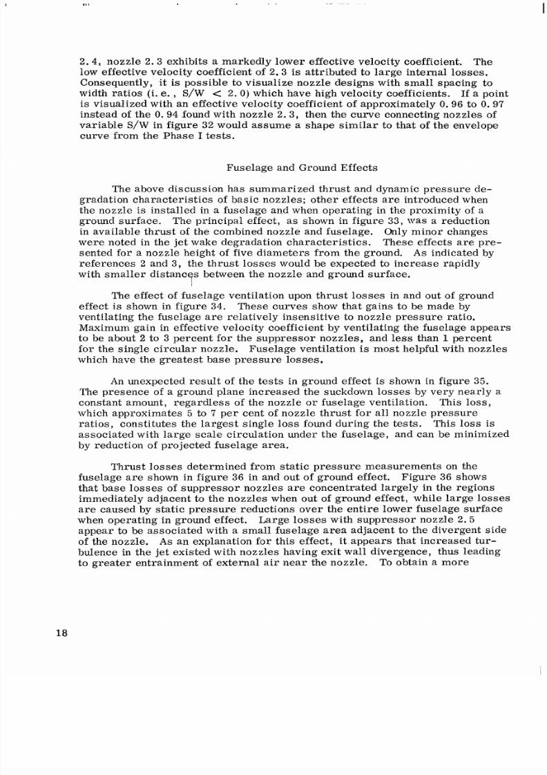
Fuselage and Ground Effects
The above discussion has summarized thrust and dynamic pressure de-
grad atio n charac teris tics of basic nozzles; other effects are introduce d when
the nozzle is installed in a fuselage and when operating in the proximity of a
ground surface. The principal effect, as shown in figure 33, was a reduction
in ava ilab le thru st of the combined nozzle and fuselage. Only minor change s
were noted in the jet wake degradation characteristics. These effects
are
pre-
sented for
a
nozzle height of five diameters from the ground.
A s
indicated by
references 2 and 3, the thrust losses would be expected to increase rapidly
with smaller distanc
s
between the nozzle and ground surface.
'i
The effect of fuselag e ventilation upon th ru st lo ss es in and out of ground
effect is shown in figure 34. These curves show that gains to be made by
ventilating the fuselage are relat ively insensi t ive to nozzle pressure rat io.
Maximum gain in effective velocity coefficient by ventilating the fuselage appears
to be about
2
to
3
percent for the suppressor nozzles, and
less
than
1
percent
for the single circular nozzle. Fuselage vent i lat ion is most helpful with nozzles
which have the greatest base pressure losses.
An unexpe cted result of the tests in ground effect
is
shown in figure
35.
The presence of a ground plane increased the suckdown losses by very nea rly
a
constant amount, regardles s of the nozzle o r fuselage ventilation. This loss,
which approximates
5
to 7 per cent of nozzle thrus t for all nozzle pre ssure
ratios, constitutes the largest single loss found d uring the tests. This loss
is
associated with large scale circulation under the fuselage, and can be minimized
by reduction of projec ted fusel age
area.
Thrust losses determined from static pressure measurem ents on the
fuselage
are
shown in figure 36 in and out of ground effect. Figure 36 shows
that base loss es of suppre ssor nozz les are concentrated largely in the regions
immedia tely adjacen t to the nozzles whe n out of ground
effect,
while large losses
are caused by
static
pressure reduct ions over the ent i re lower fuselage surface
when operating in ground effect. Large losses with suppressor nozzle
2 . 5
appear to be associated with a small fuselage area adjacent to the divergent side
of the noz zle. A s an explanation for this
effect,
it appears that increased tur-
bulence in the jet existed with nozzles having exit w all divergence, thus leading
to grea ter entr ainm ent of external air near the nozzle. To obtain a more
18

8/10/2019 CFD Exhaust jet wake and thrust characteristics of several nozzles designed for vtol downwash supresion nasa report.pdf
http://slidepdf.com/reader/full/cfd-exhaust-jet-wake-and-thrust-characteristics-of-several-nozzles-designed 22/100
positive explanation of this beh avior w ould r equire extensiv e mea sureme nts of
the flow in the nozzle, as well as more comp lete surveys of the
jet
wake and
entrainment region near the nozzle exi t .
The results obtained in tests with various fuselage and nozzle configura-
tion s wer e found to
agree
with that of oth er inve stig ator s, refe renc e 2 . These
res ult s, with the ratio of projected mod el area to nozzle exit area
as
a
primary
pa ra me te r , a re shown in f igure
3 7 .
Although only a single large fuselage
was
used in the cu rrent tests , it is apparent from figure 37 that small fuselage
projected areas will be required to avoid significant suckdown effects, particu-
lar ly when operating in ground effect. Figure 37 also shows that fuselage
ventilation assists materially in maintaining competit ive effective velocity
coefficients for the suppressor nozzle configurations. Thrust losses due to
suckdown effects associated with suppressor nozzles vary from 0 . 5 to
2 . 0
per-
cent greater than those of the c ircular nozzle.
A summary of al l thrust losse s for the variou s nozzle an d fuselageon-
figurations are shown in figure
38.
The losses are shown to be cumu lative.
Nozzles which had greatest losses in the
tests
of the basic no zzles also ex-
hibited higher suckdown losses with the fuselage and ground plane.
CONCLUDING
REMARKS
Several exh aust nozzle mo dels design ed to achieve downwash s uppress ion
of the exhaust
jets
of
VTOL
aircraft have been evaluated for jet wake d egradation
and thrust chara cteristics with both hot gases and unheated
air.
For the best suppressor nozzle and fuselage configuration tested,
dynamic pressures were reduced by
GO
to
70
per cent, d ifferential
temperatures were reduced by nearly 50 per cent, and thrust losses
increased by less than 2 per cent compared with
a
reference circular
nozzle at five nozzle diameters above the g round surface.
A
l a rge thrus t
loss
resul ted from small negat ive pressure differen-
tials acting over the lower fuselage surface in ground effect, and this
loss was nearly constant for all nozzle configurations. This loss is
related to projected
area
of the model on the ground surface.
Jet
wake degradation characteristics were strongly influenced by the
merg ing cha ract eris tics of the multiple jets. Merging of the
jets
was
pri ma ril y rel ate d to the spacing between the nozzle elements. In-
crea sing the a spe ct ra tio of the nozzle elements was effective in in-
creas ing
jet
wake degradation. Increasing the exit wall divergence
angle was effec tive in increasi ng
jet
wake degradation for the region
less than three diameters away from the nozzle exit , but related
19

8/10/2019 CFD Exhaust jet wake and thrust characteristics of several nozzles designed for vtol downwash supresion nasa report.pdf
http://slidepdf.com/reader/full/cfd-exhaust-jet-wake-and-thrust-characteristics-of-several-nozzles-designed 23/100
thrust losses resul t in an opt imum nozzle having smallxit wall
divergen ce angles, modera te aspect ratio of the elements , and a
large
spacing between the elements.
4)
Base area of the nozzle and fuselage immediately adjacen t to the
nozzle contributes significantly to the thrust losses with suppressor
type nozzles. Providing clearance between the suppressor nozzles
and fuselage was found to bean effective way to minimize these
losses. Ventilation , in the sense of providing
large
open areas
around the nozzle exit , will be necessary for best thrust performance
with suppressor nozzles. Openings on the upper fuselage surface
did not reduce thrust losses.
5)
A t
a distance of f ive diameters from the nozzle exi t , the ground
plane had only small effects upon jet wake degrada tion prior to
impingement. Effects of a fuselage upon the mixing processes
were minor,
Airplane Division, The Boeing Company
Renton,Washington
June 22, 1965
20

8/10/2019 CFD Exhaust jet wake and thrust characteristics of several nozzles designed for vtol downwash supresion nasa report.pdf
http://slidepdf.com/reader/full/cfd-exhaust-jet-wake-and-thrust-characteristics-of-several-nozzles-designed 24/100
REFERENCES
1.
Higgins, C. C.
,
andWainwright,
T. W. :
DynamicPressureandThrust
Cha rac teris tics of Cold Jets Discharging from Several Exhaust Nozzles
Designed fo r VTOL Downwash Suppressio n. NASA T N D-2263,
April 1964
2. Gentry,Gar1 L.
,
Margason,Richard
J. ,
and Kuhn,RichardE. :
Jet-
Induced B as e Lo ss es on VTOL Configurations Hovering In and Out of
GroundEffect. NASA T N D-3166
3.
Spreemann,Kenneth
P.
,
andSherm an, rving R.
:
Effects of Ground
Proximity on the Thrust of A Simple Downward-Directed
Jet
Beneath
a
Flat Surface. NACA
TN
4407,
Septem ber 1958
4.
Davenport,Edwin
E.
,
.and Spreeman ,Kenneth
P.
: ThrustCharacter i s t ics
of Multip le Lifting
Jets
in Ground Proxim ity. NASA TN D-513, Septem be r
1960
5Kuhn,Richard. : An Inves tigation oDetermineConditionsUnder Which
Downwash from VTOL Aircraft will Start Surface Erosion From
Various Type s of Te rr ai n. NASA
T N
D-56, Septem be r 1959
6. Tani, tero,andKomatsu,Yasuo : mpingeme nt of
A
Round
Jet
on
a
Flat
Surface. Presented
at
Eleven th Internationa l Congress of Applied
Mechanics,Munchen,1964
21

8/10/2019 CFD Exhaust jet wake and thrust characteristics of several nozzles designed for vtol downwash supresion nasa report.pdf
http://slidepdf.com/reader/full/cfd-exhaust-jet-wake-and-thrust-characteristics-of-several-nozzles-designed 25/100
(a)
CIRCULAR NOZZLE 1 . 1
(b) D E L T A NOZZLE
1.2
(c)
TWELVE SEGMENT
NOZZLE 1.3
Figure 1.
-
Phase I nozzles evaluated under phase 11.
22

8/10/2019 CFD Exhaust jet wake and thrust characteristics of several nozzles designed for vtol downwash supresion nasa report.pdf
http://slidepdf.com/reader/full/cfd-exhaust-jet-wake-and-thrust-characteristics-of-several-nozzles-designed 26/100
NOZZLE 2.1
NOZZLE
2.4
NOZZLE 2.7
NOZZLE 2.2
. d.,...
NOZZLE 2.5
NOZZLE 2.8
NOZZLE 2.3
NOZZLE
2.6
NOZZLE
2.9
Figure
2.
-
Non-circular nozzle configurations
for
phase
11.
23
8/10/2019 CFD Exhaust jet wake and thrust characteristics of several nozzles designed for vtol downwash supresion nasa report.pdf
http://slidepdf.com/reader/full/cfd-exhaust-jet-wake-and-thrust-characteristics-of-several-nozzles-designed 27/100
I
A, = N O Z Z L E E X I T A R E A . SQ.
IN.
Nozz le No.
A, L
W
2 . 1. 1 3 3 6
2 . 9 7 5. 5 9 5
2 . 2. 0 5 3 4
2 . 9 7 5. 5 9 5
2 . 3.11 9
2 . 9 7 5. 5 9 5
2 . 4. 0 3 0 0
2 . 9 7 5. 5 9 5
2 . 5. 1 1 5 1
2 . 9 7 5. 5 9 5
2 . 6. 1 4 6 5
2 . 9 7 5. 5 9 5
2 . 7. 0 4 0 7
2 . 9 7 5. 5 9 5
2 . 8. 0 6 4 0
2 . 2 9 8. 7 6 6
2 . 9. 0 9 0 0
4 . 2 0 0. 4 2 0
5
V
U P
1 . 7 8 5 1 . 1 4 4 1 . 2 5 0
0
1 . 7 8 5
1 . 0 5 3
1 . 1 5 0 5
0 . 8 9 2 5 0 . 5 6 7
1.000 15
1 . 1 9 0
0 . 7 8 5
1.000 15
1 . 7 8 5
0 . 9 1 5
1.000
15
2 . 3 8 0
0 . 9 4 3
1 .OOO I5
1 . 7 8 5
0 . 8 5 4 0 . 9 3 00
2 . 2 9 8 0 . 9 3 4 1 .OOO I5
1 . 2 6 0
0 . 8 4 7
1.000 15
r
2 5 O 2 7 '
27'2 1.5'
8 0 2 8 5
1 6 O 3 4 '
30 '45 '
4 1O 4 5 '
33 '28 '
3 7 0 2 7 '
22 '47 '
4
5
5
5
5
5
5
5
3
IO
s / w
3 .O
3
.O
1 . 5
2 . 0
3
.O
4 . 0
3
.O
3 .O
3
.O
Figure 3
-
Four-element suppressor nozzleconfigurations
24

8/10/2019 CFD Exhaust jet wake and thrust characteristics of several nozzles designed for vtol downwash supresion nasa report.pdf
http://slidepdf.com/reader/full/cfd-exhaust-jet-wake-and-thrust-characteristics-of-several-nozzles-designed 28/100
BELLMOUTHNSTRUMENTATIONRANSITION
SECTION
1 .o
.8
.6
m
3
I
z
U
x
W
Q -4
.2
0
E L L I P T I C A LO Z Z L E
0 4
8 1 2
T
DISTANCE FROM PLENUM
-
INCHES
Figure
4
- Typical four-element suppressor nozzle cross-sectional
area and Mach number progression
25
8/10/2019 CFD Exhaust jet wake and thrust characteristics of several nozzles designed for vtol downwash supresion nasa report.pdf
http://slidepdf.com/reader/full/cfd-exhaust-jet-wake-and-thrust-characteristics-of-several-nozzles-designed 29/100

8/10/2019 CFD Exhaust jet wake and thrust characteristics of several nozzles designed for vtol downwash supresion nasa report.pdf
http://slidepdf.com/reader/full/cfd-exhaust-jet-wake-and-thrust-characteristics-of-several-nozzles-designed 30/100
T R A V E R S I N G
C/A RAKE
q
T R A V E R S I N G
PROBE
OTAL PRESSURE R A K E 2)
G R O U N D P L A N E
7
Figure
6 -
Schematic
of
test
r i g
and facilities

8/10/2019 CFD Exhaust jet wake and thrust characteristics of several nozzles designed for vtol downwash supresion nasa report.pdf
http://slidepdf.com/reader/full/cfd-exhaust-jet-wake-and-thrust-characteristics-of-several-nozzles-designed 31/100
-
( a )
TRAVERSINGPITOTP R O B E
S U R F A C E T H E R M O C O U P L E
(TYP.)
SURFACE STATIC PRESSURE
(TYP.)
-0.125
X
0.028 W A L L
0.0625
C-A MEGAPAK
1
5
' H+.0
c )
FORTY-ONE ELEMENT TRAVERSING T H E R M O C O U P L ER A K E
( P R E S S U R E T U B E S A N D T H E R M O C O U P L E S I N T E R C H A N G E A B L E )
24.75' OD; 20" ID
P L E N U M C H A M B E R
\ N O Z Z L E
55.5 L 7 2 . 7 5 d - 3 7 4
T R A V E R S I N G J E T
WAKEPROBE
G R OU N D P L A N E
M O V E A B L E G R O U N
P L A N E (56
IN.
DIA .
I
Figure 7
- Schematic of
test
ri g and instrumentation
28

8/10/2019 CFD Exhaust jet wake and thrust characteristics of several nozzles designed for vtol downwash supresion nasa report.pdf
http://slidepdf.com/reader/full/cfd-exhaust-jet-wake-and-thrust-characteristics-of-several-nozzles-designed 32/100
(a
TEST RIG (b) TRAVERSING GROUND PL AN E
( c )
CIRCULAR NOZZLE WITHON- ( 4 NTERIOR OF FUSELAGE
VENTILATED FUSELAGE
( e ) N O Z Z L E
2.5
WITH VENTILATED ( f ) N O Z Z L E
2.5
WITH INSTRUMENTED
FUSELAGE FUSELAGE
Figure
8. - Photog raphs of test
rig
for various nozzle and fuselage configurations
29

8/10/2019 CFD Exhaust jet wake and thrust characteristics of several nozzles designed for vtol downwash supresion nasa report.pdf
http://slidepdf.com/reader/full/cfd-exhaust-jet-wake-and-thrust-characteristics-of-several-nozzles-designed 33/100
1 oo
U
6
e- .96
w
u
.92
I
Z
U
U
W
U
>
U
.88
>
W
e
1
$
84
W
U
.80
1 .o 1.2
1.4
1.6
NOZZLE
CONFIGURATION
1.1
CIRCULAR
.2
D E L T A
5 t R , 5 " f l
.3 TWELVE SEGMENT
1.8 2.0
a )
PHASE I NOZZLES
i
I
-
-
2.4
.6
Figure 9
-
Variation of effective velocity and mass
flow
coefficients
w i t h
nozzle pressure ratio for all basic nozzle configurations
30

8/10/2019 CFD Exhaust jet wake and thrust characteristics of several nozzles designed for vtol downwash supresion nasa report.pdf
http://slidepdf.com/reader/full/cfd-exhaust-jet-wake-and-thrust-characteristics-of-several-nozzles-designed 34/100
1 .oo
V
.96
c'
z
I
W
>
w
L
.84
LL
w
.80-
1 .o
1 .ocJ
.96
V
LL
I--
z
W
.52
-
LL
LL
W
V
g .88
LL
m
.84
.a0
NOZZL
1.5
1.2
NO.
-
.
--
-:;.6
N O Z Z L E f i
2.1
0"
2.2 5"
2.5 15"
2.7
30"
L
1.8
2.0
2.2 2.4
2.6
N O Z Z L I
2.1
2.2
2.5
'
/
2.7
.
1.2
S A V =
3.0
t, =
70°F
= 5.0
n
2.0 2.2 2.4 2.6
NOZZLE PRESSURE RATIO, pt /p,
n
(b) PHASE
I I
N O Z Z L E S - V A R I A T I O N OF E X I T W A LL A N G L E , I
Figure 9
-
Continued
31

8/10/2019 CFD Exhaust jet wake and thrust characteristics of several nozzles designed for vtol downwash supresion nasa report.pdf
http://slidepdf.com/reader/full/cfd-exhaust-jet-wake-and-thrust-characteristics-of-several-nozzles-designed 35/100
1 .oo
.96
.92
.88
.84
.80
1 .o 1.2 1.4
1.6
N O Z Z L E 4
2.8 3
2.5
5
2.9 10
_
1 .o 1.2 1.4
i
1.8 2.0 2.2
P
= 15"
S
W
=
3.0
tt, 70°F
1.6.8 .o 2.2
2.4.6
NOZZLE PRESSURE RATIO,
p ,/Po
c ) PHASE II
N O Z Z L E S
- VARIATION OF ASPECTRATIO,
A
2.4.6
Figure 9 - Continued
32
8/10/2019 CFD Exhaust jet wake and thrust characteristics of several nozzles designed for vtol downwash supresion nasa report.pdf
http://slidepdf.com/reader/full/cfd-exhaust-jet-wake-and-thrust-characteristics-of-several-nozzles-designed 36/100

8/10/2019 CFD Exhaust jet wake and thrust characteristics of several nozzles designed for vtol downwash supresion nasa report.pdf
http://slidepdf.com/reader/full/cfd-exhaust-jet-wake-and-thrust-characteristics-of-several-nozzles-designed 37/100

8/10/2019 CFD Exhaust jet wake and thrust characteristics of several nozzles designed for vtol downwash supresion nasa report.pdf
http://slidepdf.com/reader/full/cfd-exhaust-jet-wake-and-thrust-characteristics-of-several-nozzles-designed 38/100
6
+-
w
u
Z
U
U
W
U
>
V
W
_1
>
W
+
U
W
U
U
W
k
?
I .oo
.96
.92
.88
.84
.80
1 oo
.96
V
U
e
w
u
.92
Z
U
L L
W
U
.88
U
v
In
Q
I
.84
.80
+.
I
.o 1.2.4.6.8
2 . 0.2.4.6
- - - - - - - -
BASIC NOZZLE 2.1 IN GROUND EFFECT (Z'D,
=
5.0)
O Z Z L E
2.1
WITHNON-VENTILATED FUSELAGE OUTOF GROUND EFFE CT
BASIC NOZZLE 2.1 OUT OF GROUND EFFE CT
N O Z Z L E
2.1
WITHNON-VENTILATEDFUSELAG E N GROUND EF FEC T (Z'D, =
5.0)
2 . 4
NO ZZ LE PRESSURE RATIO, pt,'p,
(b)
SUPPRESSOR NOZZLE
2.1
WITHFUSELAGEAND GROUND PLANE .
Figure
10
-
Continued
2.6
35

8/10/2019 CFD Exhaust jet wake and thrust characteristics of several nozzles designed for vtol downwash supresion nasa report.pdf
http://slidepdf.com/reader/full/cfd-exhaust-jet-wake-and-thrust-characteristics-of-several-nozzles-designed 39/100
U
6
I--
w
u
Z
LL
W
U
U
>-
U
E
9
W
>
W
I
V
W
LL
U
W
1
1
.oo
.96
.92
.88
.84
.80
1 .o
1.2
1.4 1.6.8.0 2.2 .2. 4.6
BASIC NOZZLE 2.5 OUT OF GROUND EFFEC T
-
- -
- - - BASIC NO ZZLE 2.5 IN GROUND E FF EC T (Z.'De = 5.0)
O Z Z L E 2.5 WITH NON-VENTILATEDFUSELAG E N GROUND EFF EC T (Z'De
=
5.0)
- - N O Z Z L E 2.5 WITH NON-VENTILATED FUSELAGE OUT OF GROUND EFFE CT
t = 70°F
t "
2.4 2.6
NOZZLE PRESSURE RATIO, ptn/Po
( C ) SUPPRESSOR NOZZLE
2.5
WITH FUSELAGE AND GROUND PLAN E.
Figure 10
-
Concluded
36

8/10/2019 CFD Exhaust jet wake and thrust characteristics of several nozzles designed for vtol downwash supresion nasa report.pdf
http://slidepdf.com/reader/full/cfd-exhaust-jet-wake-and-thrust-characteristics-of-several-nozzles-designed 40/100
1 .oo
U
s .88
W
>
W
I
>
-
Y .e4
LL
LL
W
.80
t
=
70°F
NO GROUND PLA NE
'"
N O C L E A R A N C E
- - - -
-
- -
INT ERMEDIAT E CLEA RANCE
AXIMUM CLEARANCE
N O Z Z L E N O .
1 .oo
.96
U
U
I
W
Z
E
.92
L L
U
W
U
v
v
4
I
.84
.80
1
.o 1.2 1.4 1.6 1.8.0 2.2 2.4 2.6
NOZZLE PRESSURE RATIO,
t+ /Fo
( a )
F U S E L A G ECAVIT YNOTVENT ILAT ED.
Figure 11 - Effect of clearance between fuselage lower surface and nozzle
ef i t on effective velocity and
mass
flow coefficients for nozzles
1. 1, 2. 1, and 2.5 out of ground effect
37

8/10/2019 CFD Exhaust jet wake and thrust characteristics of several nozzles designed for vtol downwash supresion nasa report.pdf
http://slidepdf.com/reader/full/cfd-exhaust-jet-wake-and-thrust-characteristics-of-several-nozzles-designed 41/100
-
1
.o 1.2.4.6 1.8 2.0 2.2 2.4 2.6
=
70°F
' t "
NO CLEARANCE
MAXIMUM CLEARANC E
-
- - - - - - - - INTERMEDIATE CLEARANCE
O G R O U N D P L A N E
1
.o 1.2.4.6 I .a 2.0 2.2 2.4 2.6
NOZZLE PRESSURE RATIO, p t n / Po
(b l FUSELAGE CAVITY WITH MAXIMUM VENT ILATIO N
Figure 11
-
Concluded
3 8

8/10/2019 CFD Exhaust jet wake and thrust characteristics of several nozzles designed for vtol downwash supresion nasa report.pdf
http://slidepdf.com/reader/full/cfd-exhaust-jet-wake-and-thrust-characteristics-of-several-nozzles-designed 42/100
1
.oo
.96
U
V
b-
W
z
g
.92
U
LL
W
V
g
.88
LL
_J
In
1
.o
1.2.4 1.6 1.8
I-
i
t t
1
70'F
Z De GROUND PLANE = 5.0
n
1
1 . 1
L
-2.1
~*
I
2.5
'
1
ZZLE NO.
ll
.2
2.0
2.2.4.6
rc
#
-
1.4 1.6 1.8.0
~~
NON-VENTILATED
VENTILATED
-
- -
-
- .
2.2.4 2.6
NOZZLE PRESSURE RATIO, pt /P,
n
Figure 1 2 - Effect of fuselage ventilation on effective velocity and ma ss
flow coefficients for nozzles
1.1, 2 . 1 ,
and
2 . 5
in ground effect

8/10/2019 CFD Exhaust jet wake and thrust characteristics of several nozzles designed for vtol downwash supresion nasa report.pdf
http://slidepdf.com/reader/full/cfd-exhaust-jet-wake-and-thrust-characteristics-of-several-nozzles-designed 43/100
1 .o 1.2 1.4 1.6 1.8 2.0 2.2 2.4
2.6
NOZZLEONFIGURATION
2.6
2.6
V E N T I L A T E D
2 .8
V E N T I L A T E D
N O N - V E N T I L A T E D
2.8 NON-VENTILATED
- - -- - -
-
-
-
t = 70°F
1"
1 .oo
.96
.92
.88
.84
.@I
1 .o 1.2
NOZ ZLE PRESSURE RATIO,
p /p0
(a) OUTOF GROUND EFF EC T
t"
Figure 13 - Effect of fuselage ventilation on effective velocity and mass flow
coefficients for nozzles 2.6 and
2.8
in and out of ground
effect
40

8/10/2019 CFD Exhaust jet wake and thrust characteristics of several nozzles designed for vtol downwash supresion nasa report.pdf
http://slidepdf.com/reader/full/cfd-exhaust-jet-wake-and-thrust-characteristics-of-several-nozzles-designed 44/100
1 .oo
.96
.92
.88
.ed
.80
1
o
1 .oo
.96
U
U
I--
.92
w
u
z
U
U
W
.88
V
3
-I
U
m
.84
.80
1
I _.4
z
"".1.6
-
t = 70°F
t"
1.8
1
.o
1.2.4 1.6 1.8
N O Z Z L E
2 . 6
2.6
2.8
2 . 8
-1
2 . 0
NOZ ZLE PRESSURE RATIO,
pt,/p0
2.2.4.6
CONFIGURATION
i
. i
NON-VENTILATED
2.4.6
(b)
IN GROUND EF FEC T C / D , = 5 .0 )
Figure
13
- Concluded
4 1

8/10/2019 CFD Exhaust jet wake and thrust characteristics of several nozzles designed for vtol downwash supresion nasa report.pdf
http://slidepdf.com/reader/full/cfd-exhaust-jet-wake-and-thrust-characteristics-of-several-nozzles-designed 45/100
l~H
4
2
1
. o r
.4
-
.2
0
L
I I I
0
-4
-3
-2
- 1 0 1 \ 2
3
4
P+,/Po
=
2.0
ttn
= 1200" F
Y
Z/D,
-
0
.01
-
--.03
- .02
-.01
1
.o
0
-.01
J-.03
J-.03
-4
-3 -2
- 1 0 1 2
3
4
DISTANCEFROM
JET
CENTERLINE/EQUIVALENT CIRCULAR NOZZLE DIAMETER , X /De
( a
SURVEYS ALONG
X
AXIS.
Figure
14 -
Dynamic and
static
pressure surveys for basic suppressor nozzle
2.1
out of ground effect
4 2

8/10/2019 CFD Exhaust jet wake and thrust characteristics of several nozzles designed for vtol downwash supresion nasa report.pdf
http://slidepdf.com/reader/full/cfd-exhaust-jet-wake-and-thrust-characteristics-of-several-nozzles-designed 46/100
P,"/P0 =
2.0
t t n = 1200" F
Z/D,
0
Y
x -
I
I
0
-
501
.2
-4 -3
-2 - 1 0
1
2 3
4
0
a
I
a
-.01
-.03 _
w
L L
w
U
J L
4.0
-.03
+
I
1 0 2
m
J -.OI
-I .01
-4
-3 -2 - 1 0 1
2
3
4
DISTANCE
FROM
JET CENTER LINE EQUIVAL ENT CIRCULA R NOZZLE DIAME TER, Y/'Do,
b) SURVEYS ALON G Y AXIS
Fi,gure 14
-
Continued
43
-

8/10/2019 CFD Exhaust jet wake and thrust characteristics of several nozzles designed for vtol downwash supresion nasa report.pdf
http://slidepdf.com/reader/full/cfd-exhaust-jet-wake-and-thrust-characteristics-of-several-nozzles-designed 47/100
Y /
1.0
-
8
-
-7
.6
-
.4
-
.2
-
0
I I 1 I I I
P+,/Po
=
2.0
'tn = 1200" F
::Il
A
,
,
0
.2
0
I
.2
0
I
- 4 -3 -2 - 1
0
1 2
3
4
0 I
I
- -.01
- -.02
J
-.03
a
J -.03
"7
a
V
t
W
[II
8.0
I
I
10.0
- 1
~-
0
-
- -.02
-.01
-4
-3 -2 - 1 0 1 2
3 4
DISTANCE FROM JET CENTER LINE'EQUIVALE NT CIRCUL AR NOZZLE DIAMETER , Y/D,
( c ) SURVEY AT DISTANCE OF
0.90
INCHES FROM NOZZLE CENTERLINE.
Figure 14
-
Continued
4 4

8/10/2019 CFD Exhaust jet wake and thrust characteristics of several nozzles designed for vtol downwash supresion nasa report.pdf
http://slidepdf.com/reader/full/cfd-exhaust-jet-wake-and-thrust-characteristics-of-several-nozzles-designed 48/100
.2
0 I I I J
.4
r
I l l
-4
-3 -2
-1 0 1 2 3 4
Z,D,
/ L I
1
.o
2 . 0
3.0
4.0
8.0
10.0
1
I I 0
-.01
I t I 0
-.01
-
.02
-
' - .02
-4
-3 -2 - 1 0 1 2 3 4
DISTANCE FROM JET CENTER LINE/EQU JVALENT CIRCULAR NOZZLE DIAMETE R, Y/D,
(d)
SURVEYS AT DISTANCE OF 1.80 INCHESFROM NOZZLE CENTERLINE
Figure 14 - Continued
45

8/10/2019 CFD Exhaust jet wake and thrust characteristics of several nozzles designed for vtol downwash supresion nasa report.pdf
http://slidepdf.com/reader/full/cfd-exhaust-jet-wake-and-thrust-characteristics-of-several-nozzles-designed 49/100
Y /
Ptn/Po = 2.0
t
-
12GW F
'n -
I
Z/D,
1
1 .o
.a
.6
.4
.2
0
a
. 2
0
I
I
I 1
.2
0
I
I I 1 I
- 4
-3
-2
1
0 1 2
3
4
8.0
I 1
10.0
-.02
I 1 1 - 0
-
- -.02
-.01
-4 -3
-2 - 1 0 1 2 3
4
DISTANCE
FROM
JET CEN TERL INE EQU IVALE NT CIRC ULAR NOZZL E DIAM ETER , Y/D,
( e )
SURVEY AT DISTANCE OF 2.70 INCHESFROM NOZZLE CENTER LINE
Fig-ure 14 - Concluded
46

8/10/2019 CFD Exhaust jet wake and thrust characteristics of several nozzles designed for vtol downwash supresion nasa report.pdf
http://slidepdf.com/reader/full/cfd-exhaust-jet-wake-and-thrust-characteristics-of-several-nozzles-designed 50/100
4 6
8
10
12 14
16 180
0 2
4
6 8 10 12 14 168 20
AXIAL D IST ANCE F ROM NOZ Z LE EXIT /EQUIVALENT C IRCULA R NOZ Z LE D IAMET ER, Z 'D ,
b) TWELVE-SEGMENT NOZ Z LE
1.3
(Y = 0)
Figure
15 -
Jet
wake dynamic pressure and differential temperature surveys
of s everal basic nozz les out of ground effect
4 7

8/10/2019 CFD Exhaust jet wake and thrust characteristics of several nozzles designed for vtol downwash supresion nasa report.pdf
http://slidepdf.com/reader/full/cfd-exhaust-jet-wake-and-thrust-characteristics-of-several-nozzles-designed 51/100

8/10/2019 CFD Exhaust jet wake and thrust characteristics of several nozzles designed for vtol downwash supresion nasa report.pdf
http://slidepdf.com/reader/full/cfd-exhaust-jet-wake-and-thrust-characteristics-of-several-nozzles-designed 52/100
Y
W
N
N
W
z
3
2
1
0
1
2
3
3
2
1
0
1
2
3
4
I
X
-
I
1 2 3 4 5 6
7 8
9
10
( d )
SUPPRESSOR NOZZLE
2.1
(X
0.90
INCHES)
Ptn 'Po = 2 .0
tt,
:
200"
F
2 3
A X I A L D I ST A NC E F R O M N O Z Z L E E X I T / EQUIVALENT CIRCULAR NOZZLE DIAMETER, Z 'De
(e)
SUPPRESSOR NOZZLE 2.1 (X = 2.70 INCHES).
Figure 15
-
Continued
4 9

8/10/2019 CFD Exhaust jet wake and thrust characteristics of several nozzles designed for vtol downwash supresion nasa report.pdf
http://slidepdf.com/reader/full/cfd-exhaust-jet-wake-and-thrust-characteristics-of-several-nozzles-designed 53/100
( f ) SUPPRESSOR N OZ ZL E 2.7 X = 0.90 INCHES)
t
i
I
I
L
7
A X I A L 9 l S T A N C E F RO M N O Z Z L E E X I T
/
EQUIVALENT CIRCULAR NO ZZLE DI . \METER, Z /De
(9) SUPPRESSOR NOZ ZLE 2.7 IX = 2.70 INCHES)
Figure 15 - Concluded

8/10/2019 CFD Exhaust jet wake and thrust characteristics of several nozzles designed for vtol downwash supresion nasa report.pdf
http://slidepdf.com/reader/full/cfd-exhaust-jet-wake-and-thrust-characteristics-of-several-nozzles-designed 54/100
NOZ ZLE CONFIGURATION NOZ ZLE CONFIGURATION
m
s /w P RL S A Y A
5 3.0
0"
2.5
5 3.0
15"
5 3.0
5"
2 2.6
5 4.0
15'
5 1.5
15"
2.7
5.0
30"
5
2.0
15"
A
2.8 3 3.0
15"
0
NOZZLE CONFIGURATION
m
SAY D
L
2.9 10.05"
1.1 CIRCULAR
1.3 TWE LVE SEGMENT
1.2 D E LT A 5 a 5"
A
2
4 6 10 12 14
168
20
AXIAL DISTANCE FROM
N O Z Z L E E X I T / E Q U I V A L EN T C I R C U L A R N O Z Z L E
DIAMETER, Z/D,
i a ) NO ZZL E DISCHARGE TEMPERATURE = 70°F
1
0
2 10 12 1468
20
AXIAL DISTANCE FROM NOZZLE EXIT /EPUIVALENT CIRCULAR NOZZLE DIAMETER, ZID,
(b) NO ZZL E DISCHARGE TEMPERATURE
=
1200" F
Figure
16 - Jet
wake dynamic pressure degradation versus distance
from
nozzle exit fo r all basic nozzl e out of ground effect
51

8/10/2019 CFD Exhaust jet wake and thrust characteristics of several nozzles designed for vtol downwash supresion nasa report.pdf
http://slidepdf.com/reader/full/cfd-exhaust-jet-wake-and-thrust-characteristics-of-several-nozzles-designed 55/100
1 o
.8
.6
.4
.2
I
NOZZLEONFIGURATION
.R s w B
2.1 5 3.0 0
0
2.2
5
3.0
5'
0
2.3 5 1.55'
x 2.4
5 2.0
15'
0 2.5 5 3.0 15-
2.6 5 4.0 15'
2.7 5 3.0 3 0
E 2 . 9 IO 3.0
1 5
A
2.8
3
3.0
15'
0 1 . 1
CIRCULAR
0 1.2
D EL T A 5R 5 /3
0
1.3
TWELVE SEGMENT
2 8
10
I
I
12
14
I
," 'Po = 2.0
t, = 1200"F
n
16
18
AXIA L DISTANCE FROM hOZZ LE EXIT ,' QUIVALE NT CIRCULA R NOZZLE DIAMETER, Z./D,
NOZ ZLE DISCHARGE TEM PERATURE = 1200°F
20
Figure 1 7 -
Jet
wake differential temperature degradation versus distance
from nozzle exit for all basic no zzles out of ground effect
52

8/10/2019 CFD Exhaust jet wake and thrust characteristics of several nozzles designed for vtol downwash supresion nasa report.pdf
http://slidepdf.com/reader/full/cfd-exhaust-jet-wake-and-thrust-characteristics-of-several-nozzles-designed 56/100
1 .o
.8
c
0
\ x .6
e
LT
P
2
.4
a:
W
a:
3
v
v
W .2
a
u
a:
I
Q
E o
n
-.2
- .4
1.0
.8
.6
.4
.2
0
I
4
l l
I I I I
I
I I
"-
-
SINGLE ELEMENTHARACTERISTICS
4
6
8
IO
12 14
16
18 20
AXI AL DISTANCE FROM NOZZLE EXIT /EQIJ IVALENT CIRCULAR NOZZLE DIAMETER, Z/D,
(a) N O Z Z L E 2.1
Figure 1 8 -
Jet
wake degradation characteristics
for
several basic nozzle
configurations and survey planes
53

8/10/2019 CFD Exhaust jet wake and thrust characteristics of several nozzles designed for vtol downwash supresion nasa report.pdf
http://slidepdf.com/reader/full/cfd-exhaust-jet-wake-and-thrust-characteristics-of-several-nozzles-designed 57/100
1 .o
.8
c
e
w .6
D-
c
+
Q
IL:
x
1
v
v
W
IL:
w
.4
a
u
I
Q
z
>
.2
n
0
- .2
-
4
54
E X T R A P O L A T E D F R O M P H A S
1 1
t," =
12"O"
F -
P+,/Po
=
2.0
--
b2
-
12
14
0
2
4
6 8
124
16
18 20
AXIAL
DISTANCE
FROM
N O Z Z L E
EXIT'EQUIVALENT CIRCULAR NOZ ZLE DIAM ETER ,
Z/D,
(b) N O Z Z L E 2.3
Figure 18
- Continued

8/10/2019 CFD Exhaust jet wake and thrust characteristics of several nozzles designed for vtol downwash supresion nasa report.pdf
http://slidepdf.com/reader/full/cfd-exhaust-jet-wake-and-thrust-characteristics-of-several-nozzles-designed 58/100
1 o
.8
c
.6
8
G
2
m
I- .4
. I I - "
/--
1 - 1
1 I
I
I I
SINGLE ELEMENT CHARACTERISTICS
EXT R APO L AT ED FKUM PnASE
I
R
2 4 6 8 10
12
14 16 18
20
AXI AL DISTANCE
FROM
NOZZLE EXIT /EQUIVALENT CIRCULAR NOZZLE DIAUETER, Z/D,
c ) N O Z Z L E 2.5
Figure
18 -
Continued
55

8/10/2019 CFD Exhaust jet wake and thrust characteristics of several nozzles designed for vtol downwash supresion nasa report.pdf
http://slidepdf.com/reader/full/cfd-exhaust-jet-wake-and-thrust-characteristics-of-several-nozzles-designed 59/100
~ I 1 1 1 1 1 1 1
SINGLE ELEMENT CHARACTERISTICS
EXTRAPOLATED FROM PHASE (REF. 1)-
PtPo
=
2.0
ttn
=
1200"
Ft
I
10
12
?
8
16
2
4
6
8 10
12
14
AXIAL DISTANCE FROM N O Z ZL E EXITIEQUIVALENT CIRCULAR
N O Z Z L E
DIAMETER, 20,
(d) NOZ ZLE 2.8
Figure 18 - Continued
56

8/10/2019 CFD Exhaust jet wake and thrust characteristics of several nozzles designed for vtol downwash supresion nasa report.pdf
http://slidepdf.com/reader/full/cfd-exhaust-jet-wake-and-thrust-characteristics-of-several-nozzles-designed 60/100

8/10/2019 CFD Exhaust jet wake and thrust characteristics of several nozzles designed for vtol downwash supresion nasa report.pdf
http://slidepdf.com/reader/full/cfd-exhaust-jet-wake-and-thrust-characteristics-of-several-nozzles-designed 61/100
1 .o
.8
.6
.4
.2
0
0 2
4 6
8 IO
12 14
16
18 20
AXIAL
DISTANCE FROM NOZZ LE EXIT 'EPUIVA LENT CIRCULAR NOZZLE DIAMETER,
Z/D,
BASIC NO ZZL E OUT OF ;ROUND EF FE CT
""-
-
N O Z Z L E W I T H V E N T I L A T E DF U S E L A G E O U T O F G R O U b D E F F E C T
OZZLE WITH NON-VENTILATEDFUSELAGEOUTOF GROUND EFFE CT
FLAG
SYMBOLS
( r )
TAGNATION
PRESSURES
ON
OR
ABOVE SURFACE OF GROUND PLANE
BASIC NO ZZL E N GROUND EFF ECT (Z/D, =
5 .0 )
>
NOZ ZLE WITH NON-VENTILATED FUSELAGE N GROUND EFF ECT (Z/D,
=
5 . 0 )
a )
CIRCULAR NOZZLE
1 .1
WITH DISCHARGE TEM PERATURE
= 70"
F
'Figure 1 9
-
Effect of fuse lage and ground plane on jet wake degradation
characteris t ics
58

8/10/2019 CFD Exhaust jet wake and thrust characteristics of several nozzles designed for vtol downwash supresion nasa report.pdf
http://slidepdf.com/reader/full/cfd-exhaust-jet-wake-and-thrust-characteristics-of-several-nozzles-designed 62/100
0
l a
12 14
16
18
20
AXI AL DISTANCE FROM NOZZLE EXIT'EQUIVALENT CIRCULAR NOZZLE DIAMETER, ZD,
BASIC NOZZLE
OUT
OF GROUND EFFECT
FLA G SYMBOLS
( r ) STAGNATION P R E S S U R E S
OR
DIFFERENTIAL TEMPERATURES
ON OR
A B O V E S UR FA CE O F G R O U N D P L A N E
BASIC
N O Z Z L E
IN
G R O U N D E FF EC T
Z/D, = 5.0)
> N O Z Z L EW I T HN O N - V E N T I L A T E DF U S E L A G E IN GROUND EFFECT (Z /D, = 5.0)
0 2
4 6
8 IO
12
14
16 18 20
AXI AL DISTANCE FROM NOZZLE EXIT./EQUIVALENT CIRCULAR NOZZLE DIAMETER, Z/D,
b) CIRCULAR NOZZLE 1 . 1 WITH DISCHARGE TEMPERATURE 1200" F
Figure 19
- Continued
59

8/10/2019 CFD Exhaust jet wake and thrust characteristics of several nozzles designed for vtol downwash supresion nasa report.pdf
http://slidepdf.com/reader/full/cfd-exhaust-jet-wake-and-thrust-characteristics-of-several-nozzles-designed 63/100
0 2 4
6
a
1 0 12
14 168 20
AX IAL DISTANCE FROM NOZZLE EXIT 'EQU IVALEN T CIRCUL AR NOZZLE DIAME TER, Z/D,
B A S I C N O Z Z L E O U T O F S R O U N D E F F E C T
_
-
N O Z Z L EW IT H VEN T IL AT EDF U SEL AG EO U T O F G R O U H DEF F EC T
O Z Z L EW IT H N O N - VEN T IL AT ED F U SEL AG E O U T O F G R O U N DEF F EC T
F L AG SYMBOLS ( r ) TAGNATION P R E S S U R E S ON ORABOVE SURFACE
OF
GROUND PLANE
B A S I C N O Z Z L E IN G RO UN D EFFECT (Z/D, = 5.0)
> N O Z Z L E W I T H N O N - V E N T I L A T E D F U S E L A G E IN GR OU ND EFFECT (Z /D ,
5 .O)
( C ) SUPPRESSOR NOZZLE 2.1 WITH DISCHARGE TEMP ERAT URE 70" F
Figure
1 9
- Continued
60

8/10/2019 CFD Exhaust jet wake and thrust characteristics of several nozzles designed for vtol downwash supresion nasa report.pdf
http://slidepdf.com/reader/full/cfd-exhaust-jet-wake-and-thrust-characteristics-of-several-nozzles-designed 64/100
0 2
\
102 14680
A XI A L D IST ANCE F ROM NOZ Z LE EXIT EQUIVALENT C IRCULAR NOZ Z LE D IAMET ER, Z *'D ,
BASIC NOZ Z LCOUT OFGROUND EF F ECT
FLA G SYMBOLS
ST AGNAT ION PRESSURES
OR
DIFFERENTIA L TEMPERATURES
(r)ON OR
AB OVE SURFACE
OF
G R O U N D P L A N E
/* B A S IC N O Z Z L E N G R O U N D E FFE CT ( Z/ D ,
=
5.0)
> N O Z Z L E W I T H N O N - V E N T I L A T E D F U S E L A G E N G R O U N D E FFE CT ( Z /D , = 5.0)
.
-~
2
4
6 8
10 12 1468 20
AXIAL D IST ANCE F ROM NOZ Z LE EXIT /EPUIVALENT C IRCULAR NOZ Z LE D IAMET ER, Z 'De
(d)
SUPPRESSOR NOZZLE
2.1
WITH DISCHARGE TEMPERATURE
1200"
F
Figure 19
- Continued
61

8/10/2019 CFD Exhaust jet wake and thrust characteristics of several nozzles designed for vtol downwash supresion nasa report.pdf
http://slidepdf.com/reader/full/cfd-exhaust-jet-wake-and-thrust-characteristics-of-several-nozzles-designed 65/100
0
2
4
6
8
AXIAL DISTANCE FROM NOZZLE EXIT ’EQUIVALENT CIRCULAR NOZZLE DIAMETER, Z ID,
B A S I C N O Z Z L E O U T O F r J R O U N D E F F E C T
””- N O Z Z L E W I T H V E N T I L A T E D F U S E L A G E O U T O F G R O U K D E F F E C T
”
O Z Z L E W I T H N O N - V E N T I L A T E D F U S E L A G EO U T O F G R O U N DE F F E C T
FLAG SYMBOLS (r)
STAGNATION
P R E S S U R E S ORDIFFERENTIAL TEMPERATURES
ON OR ABOVE SURFACE OF G R O U N D P L A N E
f i
B A S I C N O Z Z L E IN G R O U N D EFFECT (Z /D, =
5.0)
N O Z Z L E WITH N O N - V E N T I L A T E D F U S E L A G E
IN
G R O U N D EFFECT (Z /D, = 5.0)
(e) SUPPRESSOR NOZZLE 2.5 WITHDISCHARGE TEMPERATURE 70” F
Figure
19
-
Continued
62

8/10/2019 CFD Exhaust jet wake and thrust characteristics of several nozzles designed for vtol downwash supresion nasa report.pdf
http://slidepdf.com/reader/full/cfd-exhaust-jet-wake-and-thrust-characteristics-of-several-nozzles-designed 66/100
0 2 4 6
8
IO 12 14 16 18 2 0
AXIAL DISTANC E FROM NOZZLE EXIT 'EPUIVALENT CIRCULAR NOZZLE DIAMETER, Z/D,
BASICNOZZLE.OUTOF GROUND EFFE CT
FLAG SYMBOLS
0 2
ST AG NA TI ON PRESSURES OR DIFFERE NTIAL TEMPERATURES
( O N OR ABOVE SURFACE OF GROUND P L A N E
/*
B A S I C N O Z Z L E IN GROUND EFFECT (Z/D, = 5.0)
> N O Z Z L E W I T H N O N - V E N T I LA T E D F U S E L A G E IN GROUND EFFECT (Z/D, = 5.0)
8 IO
12 14
16
18
6 20
AXIAL DISTANCE FROM NOZZLE EXIT/EQU IVALENT CIRCULA R NOZZLE DIAMET ER, Z.'D,
( f )
SUPPRESSOR NOZZLE 2.5 WITH DISCHARGE TEMPERATURE =
1200' F
Figure 19
-
Concluded
63

8/10/2019 CFD Exhaust jet wake and thrust characteristics of several nozzles designed for vtol downwash supresion nasa report.pdf
http://slidepdf.com/reader/full/cfd-exhaust-jet-wake-and-thrust-characteristics-of-several-nozzles-designed 67/100
WITHOUT FUSELAGE
.5
.4
.3
.2
.1
0
0 .2
.4
.6 .8 1
o
R 'De
-
0 0
.15
P+,/Po 2.0
n
.50
t tn =
1200" F
A 1.00 GROUND PL AN ET Z/D,
=
5.0
0
2.00
0 3.00
0
5.00
NON-VENTILATED FUSELAGE
.5
.4
.3
.2
. I
0
0 .2 .4
.6
.8 1 o
DYNAMIC PRESSURE RATIO OVER GROUND FL AN E,
qdq,
(a) C IR C U L ARNOZZLE 1.1
Figure 2 - Dynamic pres sure distributi on in the jet
efflux adjacent to the ground plane
64

8/10/2019 CFD Exhaust jet wake and thrust characteristics of several nozzles designed for vtol downwash supresion nasa report.pdf
http://slidepdf.com/reader/full/cfd-exhaust-jet-wake-and-thrust-characteristics-of-several-nozzles-designed 68/100
WITHOUT FUSELAGE
.2
.4 .6
.I5
S O
1 .oo
2 .oo
3.00
5.00
Y AXIS
.a
1.0 0 .2
.4
.6
.a 1.0
- - - - -
-
- - CROSS FLOW CON DITION WITH R ESPEC T TO AXES OF PROBE
NON-VENTILATED FUSELAGE
X AXIS
.2
.4
.6
.a
1.0 0 .2
Ptn /Po = 2.0
t t n
= 1200 F
GROUND PLANEAT Z/D,
5.0
I
AXIS
DYNAMIC PRESSURE RAT iO OVER GROUND PLAN E,
q d q ,
(b)
SUPPRESSOR NOZZLE 2.1
.6 .a 1 .o
Figure 20 -
Continued
65

8/10/2019 CFD Exhaust jet wake and thrust characteristics of several nozzles designed for vtol downwash supresion nasa report.pdf
http://slidepdf.com/reader/full/cfd-exhaust-jet-wake-and-thrust-characteristics-of-several-nozzles-designed 69/100
X AXIS
.5
.4
'1
.3
d
W
+
w .2
I
4
D
W
J
N
N
.1
Z
Q
-
R De
n .50
. I 5
A 1.00
0
2.00
0 3.00
0 5.00
WITH3UTUSELAGE
Y AXIS
.8 1.0 0 .2
.4
. .
. -
.
.6
-
-
-
- - - -
-
CROSSFLOW COND ITION WITH RESP ECT
T O
AXES OF PROBES
NON-VENTILATED FUSELAGE
XXIS
0
.2 .4 .6 .8
1.0
0
.2
.4
DYNAMIC PRESSURE RATIO OVER GROUND PL AN E, qq
c ) SUPPRESSOR NO ZZ LE
2.5
Pt,/Po = 2.0
t , = 1200" F
n
GROUND PLA NE AT Z/De =
5.0
-
.6
.8
Figure
20 - Concluded
66

8/10/2019 CFD Exhaust jet wake and thrust characteristics of several nozzles designed for vtol downwash supresion nasa report.pdf
http://slidepdf.com/reader/full/cfd-exhaust-jet-wake-and-thrust-characteristics-of-several-nozzles-designed 70/100

8/10/2019 CFD Exhaust jet wake and thrust characteristics of several nozzles designed for vtol downwash supresion nasa report.pdf
http://slidepdf.com/reader/full/cfd-exhaust-jet-wake-and-thrust-characteristics-of-several-nozzles-designed 71/100
.5
X AXIS
.4
.3
.2
1
E-
+
W
I
n
W
J
N
s o
5
z o
.2
.4
E
V
V
k
w
Z
J
E
P+"/P0
2 . 0
t t n = 1200" F
I
-
6
GROUND
P L A N E
A T Z / D = 5.0
W
Z
_I
Q
X AXIS
a
n .5
Z
E
w
>
.4
m
Q
W
V
Z
2 .3
n
.2
.1
0
0
2 .4 .6
-
8
WITHOUT FUSELAGE
-
.o
0
.2
.4
NON-VENTILATED FUSELAGE
Y AXIS
~~
-~
~-
~~
. 2
DIFFERENTIAL TEMPERATURE RATIO OVER GROUND
PLANE,
tdT,
b ) SVPPRESSOR N OZ ZLE 2.1
.0 0
2
.4
.8
R 4
0
\ .oo
0
2.00
.50
3.00
0
5.00
.
..
L
Figure 21 - Continued
68

8/10/2019 CFD Exhaust jet wake and thrust characteristics of several nozzles designed for vtol downwash supresion nasa report.pdf
http://slidepdf.com/reader/full/cfd-exhaust-jet-wake-and-thrust-characteristics-of-several-nozzles-designed 72/100
.2
WITHOUT FUSELAGE
X AXIS
.4 .6 .a 1 .o
P," ,Po
=
2.0
t,
=
1200 F
n
GROUND PLANE AT
Z / D :
5.0
.2
X AXIS
.6
Y AXIS
.4 .6
.a
1
.o
R De
0 0
0 S O
A
1.00
0
2.00
0
3.00
0
5.00
NON-VENTILATED FUSELAGE
Y AXIS
1.0
0 .2 .4
.8
1
.o
DIFFERENTIAL T E M P E R A T U R E RATIO O VER GROUND PLANE, t,p,
( c ) SUPPRESSOR NOZZLE 2.5
Figure
21 - Concluded
69

8/10/2019 CFD Exhaust jet wake and thrust characteristics of several nozzles designed for vtol downwash supresion nasa report.pdf
http://slidepdf.com/reader/full/cfd-exhaust-jet-wake-and-thrust-characteristics-of-several-nozzles-designed 73/100
II - c,
I
Y/D,
I
I -
c
1 1 1 - TEMPERATURES, "F
IV -
TEMPERATURES, "F
QUADRANTONFIGURATION
I
AND
IV
N O Z Z L E
1 . 1
WITHOUT FUSELAGE
II AND
1 1 1
N O Z Z L E 1 . 1 WITH NON-VENTILATEDUSELAGE
P tn /P o 2.0
t tn
= 1200°F
Z/D, GROUND PL AN E
= 5.0
(a) C I R C U L A RNOZZLE 1 .1
Figure
22
- Distribution of surface stat ic pressures and exhaust gas
temperatures adjacent to ground plane for various nozzle
and fuselage configurations
70

8/10/2019 CFD Exhaust jet wake and thrust characteristics of several nozzles designed for vtol downwash supresion nasa report.pdf
http://slidepdf.com/reader/full/cfd-exhaust-jet-wake-and-thrust-characteristics-of-several-nozzles-designed 74/100
I1
-
c,
t
I -
cp
-
1
I l l - TEMPERATURES, "F I IV - TEMPERATURES, "F
QUADRANTONFIGURATION
I AN DVOZZ LE 2.1 WITH NON-V ENTIL ATEDUSELAGE
II AND
1 1 1
NO ZZL E 2.5 WITH NON-V ENTIL ATEDUSELAGE
Ptn/Po 2.0
t tn
= 1200°F
Z/D, GROUND PL AN E = 5.0
(b) SUPPRESSOR NO ZZ LE S 2.1 AN D 2.5
Figure
22 -
Concluded
7 1

8/10/2019 CFD Exhaust jet wake and thrust characteristics of several nozzles designed for vtol downwash supresion nasa report.pdf
http://slidepdf.com/reader/full/cfd-exhaust-jet-wake-and-thrust-characteristics-of-several-nozzles-designed 75/100
mm I WITHOUT FUSELAGE
NON-VENTILATED FUSELAGE
Q
W
>
W
5 .4
m
m
W
D:
a
U
Q
Z
>
a
5 .2
I
IO
3
4
WITHOUT FUSELAGE
5
Pt,/Po
=
2.0
t t n = 1200 F
GROUND PL AN E AT Z/D,
=
5.0
3 4
NON-VENTILATED FUSELAGE
0
1
2 3 4
DISTANC E FROM CENT ER OF GROUND PLANE/EP UIVALEN T CIRCU LAR NOZZL E DIArdETER , R/De
( 0 ) C I R C U L A RN O Z Z L E 1.1
5
5
Figure
23
- Radial distribution of maximu m dynamic pressures and
dif-
ferential temperatures in theefflux over the ground plane
for various nozzle and fuselage configurations
72

8/10/2019 CFD Exhaust jet wake and thrust characteristics of several nozzles designed for vtol downwash supresion nasa report.pdf
http://slidepdf.com/reader/full/cfd-exhaust-jet-wake-and-thrust-characteristics-of-several-nozzles-designed 76/100
1
1
WITHOUT FUSELAGE
2 3 4
5 0
WITHOUT FUSELAGE
NON-VENTILATED FUSELAGE
X AXIS
Y AXIS
"
Ptn/Po
2 .0
t t n
= 1200" F
GROUND PLA rlE AT Z/D,
I5.0
3 4 5
NON-VENTILATED FUSELAGE
.-I; .;
I : [11
~.
1 3
4
5
DISTANCE FROM CENTER O F GROUND
PLANE/EQUIVALENT
CIRCULAR N O Z Z L E DIAMETER, R/D,
(b)
SUPPRESSOR N OZ ZL E 2.1
Figure
23 -
Continued
73

8/10/2019 CFD Exhaust jet wake and thrust characteristics of several nozzles designed for vtol downwash supresion nasa report.pdf
http://slidepdf.com/reader/full/cfd-exhaust-jet-wake-and-thrust-characteristics-of-several-nozzles-designed 77/100
WITHOUT FUSELAGE
N O N - V E N T I L A T E D F U S E L A t i E
1 2 3 4
n
5 0
1
2 3
4
5
X AXIS
Y AXIS
p t p 2.0
' t " = 12000F
GROUND PL ANT A T Z/De 5.0
WITHOUT FUSELAGE
DISTANCE FROMCENTEROFGROUNDPLANE/EQI
NON-VENTILATED FUSELAGE
~~ ~-
0
1 2 3
4
5
UIVALEN T CIRCUL AR NOZZLE DIAMETER, R/O,
c ) SUPPRESSOR NOZZLE 2.5
Figure
23
- Concluded
74

8/10/2019 CFD Exhaust jet wake and thrust characteristics of several nozzles designed for vtol downwash supresion nasa report.pdf
http://slidepdf.com/reader/full/cfd-exhaust-jet-wake-and-thrust-characteristics-of-several-nozzles-designed 78/100
h
i
0.5
De
CIRCULARNOZZLE 1.1 (Ptn/Po =
2.0,
t, =
l200"
F,
CIRCULAR NOZZLE REF. 6
CIRCULAR NOZZLE REF. 5
"""_
-"
0
.4
.8
1.2
1.6.0.4.0
DISTANCE FROM
CENTER
OF GROUND
PLANE/EQUIVALENT
CIRCULAR
NOZZLE DIAMETER,
R/D,
Figure 24 - Radial variation of local dynamic pressure over ground plane
for various investigations
7 5

8/10/2019 CFD Exhaust jet wake and thrust characteristics of several nozzles designed for vtol downwash supresion nasa report.pdf
http://slidepdf.com/reader/full/cfd-exhaust-jet-wake-and-thrust-characteristics-of-several-nozzles-designed 79/100
I I - N O Z Z L E 2.5 O U TFR O U N DF F E C T I
-
N O Z Z L E 2.1 O U T O FR O U N DF F E C T
a
4
v
W
V
z
I 0.
-
-
4
8
16 12 8
4 0
4 8 12 16
INCHES
111 - N O Z Z L E 2.5 INR O U N DF F E C TV - N O Z Z L E 2.1 INR O U N DF F E C T
V A L U E O F C p S H O W N A R E A C T U A L V A L U E S
X
100
(a)
STATICPRESSUREDISTRIBUTION ON TH E LCWERFUSELAGESURFACE, cp
Ptn /Po =
2.0
ttn
= 1200
O
F
162 8
4
0
4
8 12 16
INCHES
Ill
-
N O Z Z L E 2.5 INR O U N DF F E C TV
-
N O Z Z L E 2.1 INR O U N DF F E C T
(b)
TEMPERATURE DISTRIBUTIONADJACENT TOTHE LOWER FUSELAGE SURFACE, F
Figure 25 - Static pressure and temperature distributions on lower surface
of non-ventilated fuselage for various nozzle configurations
76

8/10/2019 CFD Exhaust jet wake and thrust characteristics of several nozzles designed for vtol downwash supresion nasa report.pdf
http://slidepdf.com/reader/full/cfd-exhaust-jet-wake-and-thrust-characteristics-of-several-nozzles-designed 80/100
-
.003
-
.002
- .001
0
1 -
1
3 4 5 6 7
DISTANCE FROM CENTER OF GROUND PLANE/EQUIV ALENT CIRCULAR NOZZLE DIAME TER, RID,
0
n
I
Ln
n
-
- - ON-VENTILATED FUSELAGE
a
u - VENTILATED FUSELAGE
IN GROUND EFF EC T (Z/D, = 5.0)
I
z
w
-
2 --------
NON-VENTILATEDUSELAGE
LL
LLI
P+
/Po
=
2.0
t" -
LL O U T O F G R O U N DF F EC T
n
VENTILATED FUSELAGE
t - 7 0 ° F
- ,003
- 002
-
.001
0
0 1 2 3 4 5 6 7
DISTANCE FROM CENTER OF GROUND PLANE /EQUIVA LENT CIRCULA R NOZZLE DIAME TER, R/D,
( 0 )
C IR C U L ARNOZZLE 1 .1
Figure 26 - Radial distribution
of
pressures induced on the lower
surface of the fuselage by the jet
77

8/10/2019 CFD Exhaust jet wake and thrust characteristics of several nozzles designed for vtol downwash supresion nasa report.pdf
http://slidepdf.com/reader/full/cfd-exhaust-jet-wake-and-thrust-characteristics-of-several-nozzles-designed 81/100
-
.012
-
.008
-
.004
0
- T
LAJOR
X I S
I 1
0 1 2 3 4
5 6
7
DISTANCE FROM
CENTER OF
GROUND
PLANE/EQUIVALENT
CIRC ULAR NOZZLE OIAME TER, R/D,
a
I
y1
NON-VENTILATED FUSELAGE
VENTILATED FUSELAGE
a
IN GROUND EF FE CT (Z/D,
5.0)
-
V
E
z ON-VENTILATEDUSELAGE
+
u
VENTILATEDUSELAGE
O U T O F G R O U N D E F F E C T
L L
U
W
V
W
- .020
,016
-
,012
-
,008
-
.004
0
I
I
. i
0
1
2
3
NOR AXIS
i
.
. -
I
4
-
-
DISTANCE FROM CENTER OF GROUND PLANE/EQ UIVALENT CIRCU LAR NOZZL E DIAMETER , R/D,
(b) SUPPRESSOR NOZZLE 2.1
Figure 26
-
Continued
78
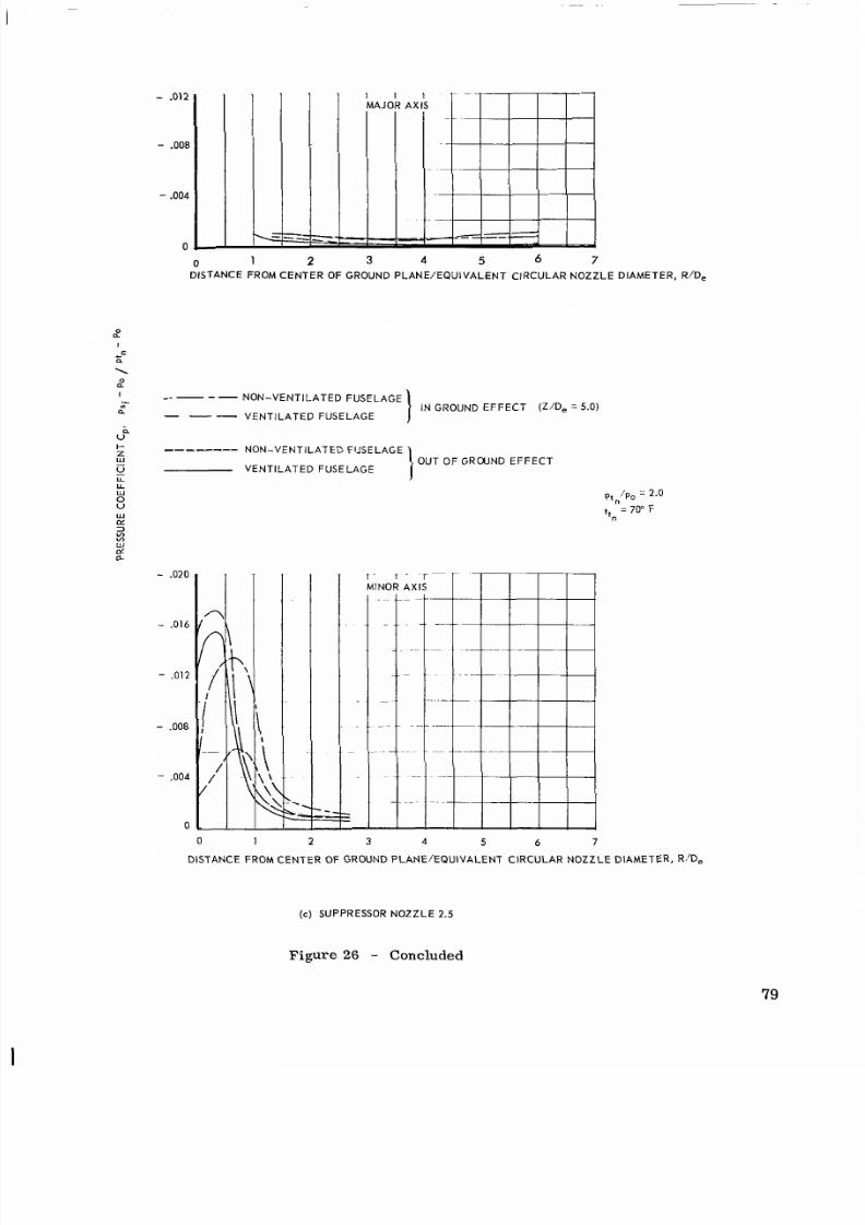
8/10/2019 CFD Exhaust jet wake and thrust characteristics of several nozzles designed for vtol downwash supresion nasa report.pdf
http://slidepdf.com/reader/full/cfd-exhaust-jet-wake-and-thrust-characteristics-of-several-nozzles-designed 82/100
- .012
-
.008
-
.004
0
0
1
2 3 4 5 6 7
DISTANCE FROM CENTE R OF GROUND PLANE/EQUIVALENT CIRCULAR NOZZLE DIAMETER, R/De
0
n
I
NON-VENTILATEDUSELAGE
a
-
VENTILATEDFUSELAGE
I
IN GROUND E FFECT Z /De = 5.0)
V"
I-
z
ON-VENTILATEDFUSELAGE
w
u
VENTILATED FUSELAGE
O UT O F G R W N D E F F E C T
-
.020
1 - I
MINOR 1
3 4 5 6 7
DISTANCE FROM CENTER OF GROUND PLAN E/EQU IVALEN T CIRC ULAR NOZZ LE DIAME TER, R/D,
c ) SUPPRESSOR NOZZLE
2.5
Figure 26 - Concluded
79

8/10/2019 CFD Exhaust jet wake and thrust characteristics of several nozzles designed for vtol downwash supresion nasa report.pdf
http://slidepdf.com/reader/full/cfd-exhaust-jet-wake-and-thrust-characteristics-of-several-nozzles-designed 83/100
1 o
.8
.6
.4
.2
0
0
5050 25 30
EXIT WALL ANGLE,
19,
DEGREES
1
o
.8
.6
.4
.2
0
2/D,
0 0
0 1
$ 2
e13
0 4
0 6
D 8
x 10
P
15
Q
20
Q
Z
0 2 4 6
8 10
12
n
ASPECT RATIO, 4
Ptn/Po
=
2.0
ttn = 70" F
1 .o
.8
.6
.4
.2
0
0
1
2
3 4 5 6
SPACING RATIO, S A
(a) NOZ ZLE DISCHARGE TEMPERATURE = 70" F
Figure 2 7 - Dynamic pres sure degradati on versus
exit
wall angle, aspect
ratio, and spacing ratio for all basic suppressor nozzles out
of ground effect
8

8/10/2019 CFD Exhaust jet wake and thrust characteristics of several nozzles designed for vtol downwash supresion nasa report.pdf
http://slidepdf.com/reader/full/cfd-exhaust-jet-wake-and-thrust-characteristics-of-several-nozzles-designed 84/100
1
.o
.8
.6
.4
.2
0
0 5 10 15 2 0 25 30
EXITA L LNGLE,
,
DEGREES
0 2 4 6 8 10 12
ASPECTRATIO, 4
I
. .
Ptn/Po = 2.0
tt,
=
1200" F
0
1 3 4 5 6
SPACING RA TIO, S/W
(b) NOZ Z LE D ISCHARGE T EMPERAT URE
=
1200"
F
Z/D,
0
1
2
3
4
6
8
10
15
20
Figure 27
-
Concluded
81

8/10/2019 CFD Exhaust jet wake and thrust characteristics of several nozzles designed for vtol downwash supresion nasa report.pdf
http://slidepdf.com/reader/full/cfd-exhaust-jet-wake-and-thrust-characteristics-of-several-nozzles-designed 85/100
1 .o
.8
.6
.4
.2
0
0 5 10 15 20 25 30
EXIT WALL ANGLE,
p,
DEGREES
1 .o
.8
.6
.4
.2
0
0 2 4 6 a 10 12
Z/D,
0 0
0 1
0 2
0 4
0 3
ASPECT RATIO, +R
P," 'Po
= 2.0
t
-
1200°F
+"
-
1
.o
.8
.6
.4
.2
0
0 1 2 3 4
5
6
SPACING RATIO, S N
NOZ ZLE DISCHARGE TEMPERATURE = 1200" F
Figure
28
- Differential temperature degradation versus exit wall
angle,
aspect ratio, and sp acing ratio for all basic suppressor
nozzles out of ground effect
82

8/10/2019 CFD Exhaust jet wake and thrust characteristics of several nozzles designed for vtol downwash supresion nasa report.pdf
http://slidepdf.com/reader/full/cfd-exhaust-jet-wake-and-thrust-characteristics-of-several-nozzles-designed 86/100

8/10/2019 CFD Exhaust jet wake and thrust characteristics of several nozzles designed for vtol downwash supresion nasa report.pdf
http://slidepdf.com/reader/full/cfd-exhaust-jet-wake-and-thrust-characteristics-of-several-nozzles-designed 87/100
0 2
1
o
.8
.6
.4
.?
0
'E I
1
.
4
...
6 8
10
1 2 14 16
AX IAL DISTANCE FROM NOZZLEEXIT /EQUIVALENTCIRCULARNOZZLEDIAMETER, Z/D,
.2
.4
,
I . -
Z 'DL
0 1 -
0 3
0 4
D 5
D 6
0 8
x
10
.
17 15
:2.5
7.5 '
Q
20
.6
.8
1 .o 1 . 2 1.4 1.6.8 2.0
TRANSVERSE MIXING DISTANCE RATI0S.X X,50r
=rno.x
( b ) CIRCULARNOZZLE
1 . 1
- DIFFERENTIALTEMPERATURERATIO
Figure 29 -
Continued
84

8/10/2019 CFD Exhaust jet wake and thrust characteristics of several nozzles designed for vtol downwash supresion nasa report.pdf
http://slidepdf.com/reader/full/cfd-exhaust-jet-wake-and-thrust-characteristics-of-several-nozzles-designed 88/100
5 -
4 -
3 -
GEOMETRY
OF
M I X I N G Z O N E
BOUNDARY
OF
"APPARENT CORE"
-
X =
TRANSVERSE M IX IN G
-
DISTANCE FROM BOUNDARY
OF
"APPARENT CORE" AL ONG
X AXIS.
-
Y
=
ANALOGOUS TRANSVERSE
-
M I X I N G DI ST A NC E A L O N G
Y
AXIS.
-
0
1
.o
.8
.6
.4
.2
2
4
6
R
10
12
14
16
18
A X I A LDIST ANCEF ROMNOZ Z LEEXIT /EQUIVALENTCIRCULARNOZ Z LEDIAMET ER,
Z/D,
I 1 1
- LA IN SYMBOLS = VALUES OF x 1 X . 2 5
D 6
D
-
F L A G
S YM BO LS ( / ) = V A L U E S O F Y/Y.
L
.8
1
.o
1.2 1.4.6 1.8 2
.o
TRANSVERSEMIXINGISTANCEATIOS,/X.25, 8. Y l y . 2 5 q z m a x
'max
( c ) NOZZLE 2.1 - DYNAMICPRESSURERATIO
Figure 29 -
Continued
85

8/10/2019 CFD Exhaust jet wake and thrust characteristics of several nozzles designed for vtol downwash supresion nasa report.pdf
http://slidepdf.com/reader/full/cfd-exhaust-jet-wake-and-thrust-characteristics-of-several-nozzles-designed 89/100
~
L
0 .2 .4
.6
.a 1 o
1.2 1.4
1.6 1 .a 2.0
" . . . 3
TRANSVERSE MIXING ISTANCE ATIOS,X/X,gfir 8 Y/Y.50rmOX
mox
(d) N O Z Z L E
2.1
- DIFFERENTIAL T EMPER AT U R ERATIO
Figure
29 -
Continued
86
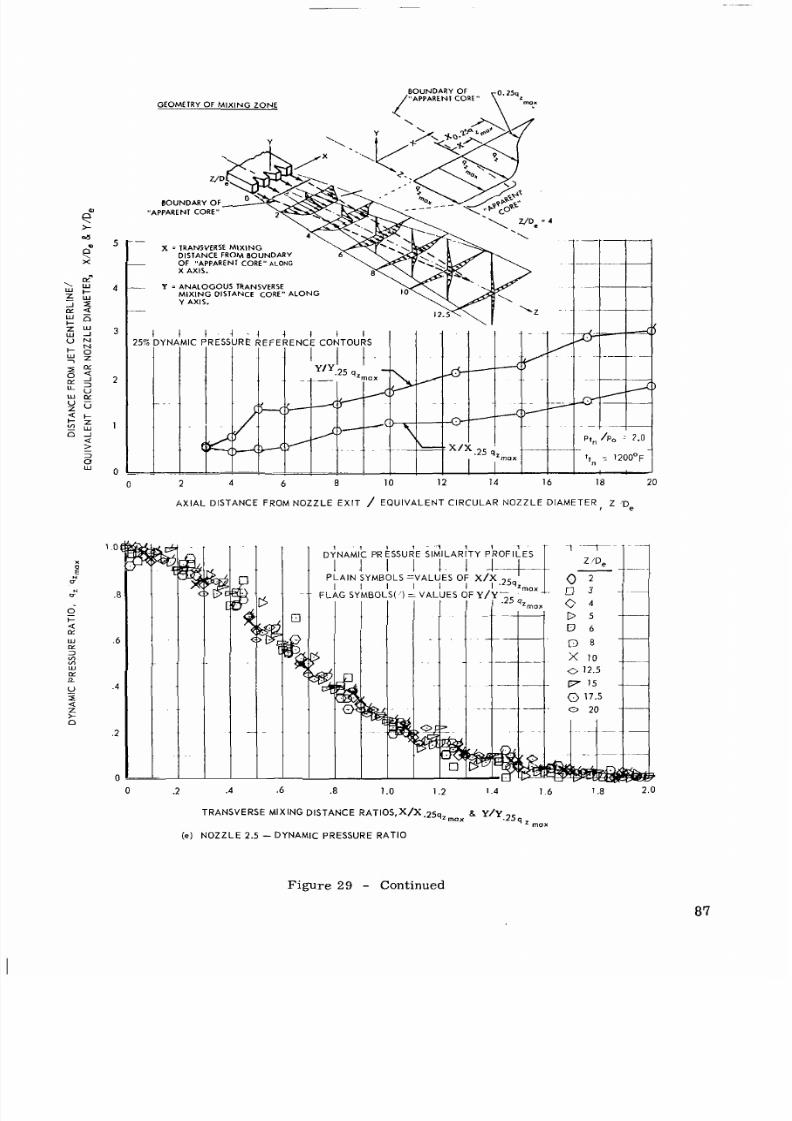
8/10/2019 CFD Exhaust jet wake and thrust characteristics of several nozzles designed for vtol downwash supresion nasa report.pdf
http://slidepdf.com/reader/full/cfd-exhaust-jet-wake-and-thrust-characteristics-of-several-nozzles-designed 90/100
GEOMETRY OF M I X I N G Z O N E
/ "APPARENI
CORE
B O U N D A R Y
OF
B O U N D A R Y OF
"APPARENT CORE"
X = TRANSVERSE M I XI NG
DISTANCE FROM B O U N D A R Y
Y = ANALOGOUS TRANSVERSE
0 2 4 6
8
IO 12 14 16 18 20
AXI AL DISTANCE FROM N O Z Z L EEXIT / EQUIVALENTCIRCULARNOZZLEDIAMETER, Z
' D ~
.a
.6
.4
.2
0
0
.2
.4
.6 .8 1 .o 1.2 I 4 1 6 1.8 2 .0
TRANSVERSE MIXINGISTANCEAT10S,X/X~~5q,mox
g m o x
( e )
N O Z Z L E 2.5 - DYNAMIC PRESSURE RATIO
Figure
29 -
C o n t i n u e d
87

8/10/2019 CFD Exhaust jet wake and thrust characteristics of several nozzles designed for vtol downwash supresion nasa report.pdf
http://slidepdf.com/reader/full/cfd-exhaust-jet-wake-and-thrust-characteristics-of-several-nozzles-designed 91/100
\
W
Z
J
W
@L
I
Z
V
W
-
I
CL:
LI
W
N
J
N
z
W
u
Z
6
E
I-
n
AXIA L DISTANCE FROM NOZZL E EXIT /EQUIVALENT CIRCULAR NOZZLE DIAMETER, Z/C,
1
0 .2
.4
.6 .8 1 o 1.2 1.4 1.6 1.8 2.0
TRANSVERSE MIXING DISTANCE
RATIOS,
X h . 5 0 ~ a Y / y . 5 0 ~
'max ' m a x
( f ) N O Z Z L E 2.5
-
D I F F E R E N T I A L T E M PE R A TU R E R AT I O
Figure 29
-
Concluded
88

8/10/2019 CFD Exhaust jet wake and thrust characteristics of several nozzles designed for vtol downwash supresion nasa report.pdf
http://slidepdf.com/reader/full/cfd-exhaust-jet-wake-and-thrust-characteristics-of-several-nozzles-designed 92/100
1
o
.8
.6
.4
.2
0
0 .2 .4 .6 . 8 1 .o
DIF F ERENT IAL T E M P E R A T U R ERAT IO, T r m a x T n
(a) DYNAMICPRESSURE
R A T I O
VERSUS DIFFERENTIALT E M P E R A T U R ER A T I O
N O Z Z L E
7 2.1
0
0
2.2
2.3
X
2.4
0
2.5
2.6
2.7
n
2.8
II
2.9
0 1.1
0
0 1.2
1.3
Ptn/Po = 2.0
tt,
=
1200” F
2 4 6 8 10
12
14 16 18 20
A X I A L
D I S T A N C E
F ROM NOZ Z LE EXIT /EPUIVAL ENT C IRCULA R NOZ Z LE D IAMET ER. Z/’D,
(b)
VARIAT ION WIT H D IST ANCE F ROM NOZ Z LE EXIT
Figure 30 - Comp arison of d ynam ic pres sure degr adati on with differential
temperature degradation for all basi c nozzles out of ground effect
89

8/10/2019 CFD Exhaust jet wake and thrust characteristics of several nozzles designed for vtol downwash supresion nasa report.pdf
http://slidepdf.com/reader/full/cfd-exhaust-jet-wake-and-thrust-characteristics-of-several-nozzles-designed 93/100
N O Z Z L E
CONFIGURATION
-
1 .o
.a
.6
.4
.2
0
0
2
4 6
8 10
12
14
16
18
20
AXIAL DISTANCE FROM
N O Z Z L E
EXIT/EQUIVALENT CIRCULAR NOZZ LE DIAMETER, VD,
Figure 31
-
Jet wake degradation characteristics of supp ressor nozzl es
relative
to
the degradation characteristics of a circular
nozzle
for
all
basic nozzles out of ground effect
90

8/10/2019 CFD Exhaust jet wake and thrust characteristics of several nozzles designed for vtol downwash supresion nasa report.pdf
http://slidepdf.com/reader/full/cfd-exhaust-jet-wake-and-thrust-characteristics-of-several-nozzles-designed 94/100
1 .o
.8
.6
.4
.2
0
.%
1
.o
.8
.6
.4
.88 .90 .92 .94 .96 .98 1 .oo
NOZZLEONFIGURATION
& S'W f
7
2.1 5 3.0
0"
0
2.2
5
3.0
5"
0
2.3
5
1.5
15"
x
2.4
5
2.0
15"
2.5
5
3.0
15"
0
2.6
5
4.0
15"
2 . 7
5 3.0
30"
A
2.8
3 3.0 15"
b
2.9 10
3.0
15"
0 1 . 1
CIRCULAR
0
1.2
D E L T A 5 & ,
0 1.3
TWELVE SEGMENT
Pt,/Po =
2.0
tt"
=
1200'F
Z/D,
= 5.0
.86 .88 .90 .92 .94 .9698 1 .oo
EFFECTIVE VELOCITY COEFF ICIENT, Cve
Figure 32 - Jet wake degradation versus thrust of basic nozzles
for free jet tests
9 1

8/10/2019 CFD Exhaust jet wake and thrust characteristics of several nozzles designed for vtol downwash supresion nasa report.pdf
http://slidepdf.com/reader/full/cfd-exhaust-jet-wake-and-thrust-characteristics-of-several-nozzles-designed 95/100
1
.@
.8
.6
.4
.2
@
1
o
1.2.4.6.8
1I
_i
2 . 0
tt
1
.2
2.4.6 2.8
NO ZZL E PRESSURE RATIO,
Ptn/Po
CIRC ULAR NOZ ZLE 1.1, OUT OFGROUND EFFECT
SUPPRESSOR NO ZZ LE 2.1, OUT OF GROUND EFF EC T
SUPPRESSOR NOZZLE
2.5,
OUT OF GROUND EFFECT
-
@
C I R C U L A RNOZ ZLE 1.1, IN GROUND EFF ECT (Z/D, z5.0)
0'
SUPPRESSOR NO ZZ LE 2.1, IN GROUND EFFE CT
(Z/D, = 5.0)
SUPPRESSOR NOZZLE 2.5, N GROUND EFF ECT (Z/D, =5.0)
0 2
4
IO
124 168
20
AXIAL DISTANCE FROM NOZZLEEXIT /EPUIVALENTCIRCULARNOZZLEDIAMETER, z/D,
Figure 33 -
Comparison of thru st and dynam ic press ure degr adatio n of
nozzles
1.1,
2.1, and 2.5 with non-ventilated fuselage
in
and out of ground effect
92

8/10/2019 CFD Exhaust jet wake and thrust characteristics of several nozzles designed for vtol downwash supresion nasa report.pdf
http://slidepdf.com/reader/full/cfd-exhaust-jet-wake-and-thrust-characteristics-of-several-nozzles-designed 96/100
.04
.03
.02
.01
0
O U T O F G R O U N D E F F E C T
1.4 1.6 1.8.0
N O Z Z L E
1 .1
2.2.4 2.6
IN GROUND EF FE CT (Z/D, = 5.0)
1 .o 1.2 1.4 1.6 1.8 2.0 2.2 2.4 2.6
NOZZLE PRESSURE RATIO, P,,/P~
Figure
34
- Effect of fuselage ventilat ion on effective velocity coefficien ts
for various nozzle and fuselage configurations
93

8/10/2019 CFD Exhaust jet wake and thrust characteristics of several nozzles designed for vtol downwash supresion nasa report.pdf
http://slidepdf.com/reader/full/cfd-exhaust-jet-wake-and-thrust-characteristics-of-several-nozzles-designed 97/100
.... .." ~
e
0
0)
L?
I-
W
I-
z
n
w
u
L L
_I
W
>
W
U
U
W
NON-VENTILATED FUSELAGE
1
o
1.2
I .4
1.6.8
2.0
2.2 2.4 2.6
N O Z Z L E
1.1 t, = 70" F
n
-
- -
- -
- -
-
-
-
2.1
2.5
2.6
2.8
"-"
Z/D,
=
5.0
VEN T IL AT ED F U SEL AG E
LL
1
o
1.2 .4 1.6 1.8 2.0 2.2
2.4
2.6
NOZZLE PRESSURE RATIO, pt,/po
Figure
35
- Effect of ground proxi mity on effective velocity coefficients
of various nozzle and fuselage configurations
94

8/10/2019 CFD Exhaust jet wake and thrust characteristics of several nozzles designed for vtol downwash supresion nasa report.pdf
http://slidepdf.com/reader/full/cfd-exhaust-jet-wake-and-thrust-characteristics-of-several-nozzles-designed 98/100
I I
-
SUPPRESSOR NO ZZL E
2.1 8.2.5
C IR C U L AROZZLE
1.1
I
(NON-VENTILATED)NON-VENTILATED)
I l l
- IV -
SUPPRESSOR NOZZLE 2.1 8 2.5 CIRCULAR OZZLE 1.1
(VENTILATED)
1 00
40
Q
I
U
I
Z
w
a
NOZZL E NO.
n
I-
U
a
U
Z
u
I- 2 0
a
w
II Ill IV
QUADRANT
Pt,/Po =
2.0
t,, = 70" F
3
1 .1 2.1
c
A
9 3
2 -
.'
2.5
O U T O F G R O U N D EF F EC T
1 .1
49
2.1 2.5
IN GROUND EFFECT (Z/D, = 5.0)
Figure
36
- Relative distribution of thrust losses for various nozzle
and fuselage configurations
9 5
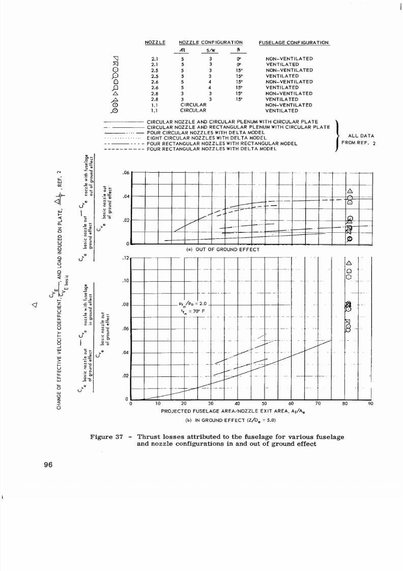
8/10/2019 CFD Exhaust jet wake and thrust characteristics of several nozzles designed for vtol downwash supresion nasa report.pdf
http://slidepdf.com/reader/full/cfd-exhaust-jet-wake-and-thrust-characteristics-of-several-nozzles-designed 99/100
NOZZLEOZZLEONFIGURATIONUSELAGEONFIGURATION
A
SAV
P
-
c 2.1
5 3
0 N O N - VEN T IL AT ED
2.1
5
3
(P V E N T I L A T E D
5
3 15" N O N - VEN T IL AT ED
2.5 5
3
15'
V E N T I L A T E D
2.6 5
4
1
5"
N O N - VEN T IL AT ED
2.6 4 15" V E N T I L A T E D
n
2.8 3 3
15
N O N - VEN T IL AT ED
2.8
3 3
15" V E N T I L A T E D
1.1
CIRCULAR
N O N - VEN T IL AT ED
;
2.5
;
g
J 3 1.1 C IR C U L AREN T IL AT ED
CIRCULAR NOZZLE AND CIRCULAR PLENUM WITH CIRCULAR PLATE
- .
C IR C U L AR N O Z Z L EN D R EC T AN G U L ARL EN U MW IT H C IR C U L ARL AT E
-
OUR CIRCULAR NOZZLES WITH DEL TA MODEL
. . .
. . .
. . . .
.
.
.
EIGHTIRCULAROZZLES WITH DE LTA MODEL ALLA T A
-
-
-
- -
-
FOUR RECTANGULAROZZLESWITHECTANGULARMODEL FROM REF. 2
-
--
-
---- - F O U R R E C T A N G U L A R N O Z Z L E S W I T H D E L T A M O D E L
.06
.04
.02
0
(a) OUT OF GROUND EFFEC T
PROJECTED FUSELAGE AREA/NOZZLE EXIT AREA, Af/A,
b)
IN GROUND EFFECT (Z/D, = 5.0)
0
Figure 37 -
Thrust losses attr ibuted
to
the fuselage for various fuselage
and nozzle configurations
in
and out
of
ground effect
96

8/10/2019 CFD Exhaust jet wake and thrust characteristics of several nozzles designed for vtol downwash supresion nasa report.pdf
http://slidepdf.com/reader/full/cfd-exhaust-jet-wake-and-thrust-characteristics-of-several-nozzles-designed 100/100
+-
w
U
U
W
U
>
U
W
-I
>
.16
k
.I2
W
.08
k
x
U
W
LL
W
Q
z
I
.04
v o
BASIC NOZZLE LOSSES
ADDIT IONA L LOSSES DUE TO FUSELAGE
a DDITIONAL LOSSES DUE
TO
GROUND PROXIMITY (Z/D, =
5.0)
. .
.
:.......
.
.. ..
.
.
.
. ..
.
.
.
_..
. ..
.
.....
. . .
.
.
.
L?
A
P
P
1
. I
2.1 2.5
2.6
Pt"/P0
= 2.0
ttn = 70"
F
k .
P
2.8
N O Z Z L EN U MBER