Embed Size (px)
Citation preview

CFD ANALYSIS OF AIRFLOW CHARACTERISTICS IN OFFICE ROOM WITH TASK AIR-CONDITIONING AND NATURAL VENTILATION
Eunsu Lim 1†, Kazunobu Sagara 1, Toshio Yamanaka 1, Hisashi Kotani 1,
Noriaki Mishima 2, Susumu Horikawa 3, and Tomoaki Ushio 3
1Department of Architectural Engineering, Osaka University, Japan 2The Kansai Electric Power CO. INC., Japan
3NIKKEN SEKKEI LTD., Japan
ABSTRACT The performance of indoor airflow for the office room with the hybrid air-conditioning system has been investigated by means of CFD analysis. The hybrid air-conditioning system is composed of under floor air supply outlets for task zone and the natural ventilation openings for ambient zone. The measured data (Kotani et al. 2006) at the office room in existence was used as the boundary condition of the flow rate of each natural ventilation opening and task flow outlets for CFD. To investigate the influence of location of the natural ventilation opening, two models with different location of openings for natural ventilation were made; one is the case with openings for natural ventilation under the ceiling (“ceiling-model”; Lim et al. 2007) and the other is the case with openings for natural ventilation near the window side (“counter-model”). It was made clear that the ceiling-model can supply the fresh air more widely to the occupancy zone than counter-model. Moreover, CFD analysis using ceiling-model was conducted to investigate the influence of the outdoor air condition (wind direction, wind velocity and outdoor temperature). As the results, the distribution of fresh air under the north wind is more uniform than that of the west wind. Under the west wind, SVE4 of natural ventilation openings is highest in the west-side zone. KEYWORDS Task air-conditioning system, Natural ventilation, SVE4, CFD
INTRODUCTION Recently, hybrid ventilation, which has air-conditioning and natural ventilation, is proposed. It is important to know the airflow characteristics in the room with the hybrid ventilation to use it well. The aim of this study is to investigate the airflow characteristics in the office room with hybrid ventilation, which is influenced by the location of natural ventilation openings and outdoor air condition (wind direction, wind velocity and outdoor temperature, etc.). The office room, the target of this study, is located in the 30th floor (the height of FL+131.63m) of a high-rise office building in Osaka, Japan. As presented in previous papers (Ushio et al. 2006) (Kotani et al. 2006), the HAVAC system of this building was designed to control the occupancy zone by the under floor air-conditioning and the ambient zone by the natural ventilation in intermediate seasons. In summer and winter seasons, all the natural ventilation openings are closed, and the indoor environment is to be controlled by so-called “task and ambient air-conditioning system” (Yamanaka et al. 2007). Outline of air-conditioning system and the results of measurement will be presented in another paper (Ushio et al. 2007). This paper presents the results of the air characteristics of the office room in intermediate seasons analyzed by means of CFD. The influence of location of natural ventilation openings and outdoor air condition (wind direction, wind velocity and outdoor temperature) will be discussed. The distribution of velocity, † Corresponding Author: Tel: +81-6-6879-7645, Fax: +81-6-6879-7646 E-mail address: [email protected]

temperature and scale for ventilation efficiency No.4 (SVE4; Murakami and Kato et al. 1994) was used to examine the airflow characteristics of the zone in the height of seated occupants (FL+1100mm). It can be said that SVE4 presents the contribution ratio of each supply outlet at a certain point in the room. OUTLINE AND RESULTS OF CFD ANALYSIS
Model of CFD analysis
Table 1 shows the outlines of CFD analysis. The analysis model consists of the office and the workspace in the southwest as shown in Figure 1. Two models with different location of the natural ventilation openings were made in this research; they are settled below the ceiling near window in ceiling-model and on the counter by the window in counter-model (see Figure 1. (2) and (3)). The flow rate of each natural ventilation opening was calculated from the measured wind pressure coefficients (Kotani et al. 2006) under the outdoor velocity of 5m/s. In the case of ceiling-model, the size of a natural ventilation opening is 120×10cm and the outdoor air was supplied into the room with an angle of 20 degrees to the ceiling. In counter-model, the size of a natural ventilation opening is 120×20cm and the air was supplied into the room with an angle of 45 degrees to the window. The size of mesh is 20×20×20cm except the vicinity of the natural ventilation openings. A task outlet (under task outlet) was assumed to be a 400×400mm horizontal plane and the airflow direction was upward vertically. Table 2 shows the boundary conditions of CFD. Lighting equipment and exhaust openings were installed on the ceiling. The total flow rate of exhaust air is equal to the total amount of air from the task outlet. The outdoor condition for CFD analysis is shown in Table 3. This paper presents the influence of natural ventilation opening location, wind direction, velocity and outdoor temperature on the airflow characteristics in the room. In the examination of the influence of the location of natural ventilation openings, ceiling-model and counter-model were compared under the
Table 2 Boundary conditions
Table 1 Outlines of CFD analysis
Table 3 Analysis conditions
Figure 1. Analysis area

outdoor conditions of 17.5ºC (temperature), west wind (wind direction) and 5m/s (velocity). To examine the influence of outdoor wind direction using ceiling-model, wind direction was set at west, northwest and north in turn. In this case, temperature and velocity are fixed at 17.5ºC and 5m/s. In each condition, the inflow openings are W1~4 and E3 for west wind, W1~4, N1~4, N7 and N8 for northwest wind, and N1~4 and N7~10 for north wind. To examine the influence of outdoor temperature using ceiling-model, temperature of 17.5ºC, 20ºC and 25ºC are assumed. In this case, wind direction and velocity are set at west and 5m/s. In the examination of the influence of the wind velocity, wind velocity was set at 2.5m/s, 5m/s and 10m/s in turn. In this case, wind direction and outdoor temperature are fixed at west wind and 17.5ºC.
RESULTS
Influence of the location of natural ventilation openings on the indoor airflow (ceiling-model case and counter-model case)
WEST WIND
SVE4 presents the contribution ratio of each supply outlet in a certain point within the room. Here, SVE4-NV is defined as the contribution ratio all natural ventilation openings in a certain point within the room. The distribution of velocity, temperature and SVE4-NV at AA’ section and FL+1100mm plane (see Figure 1) are shown in Figure 2 and Figure 3. The velocity in this plane is ranging from about 0.1 to 0.4m/s in ceiling-model and less than 0.2m/s in counter-model, except the vicinity of natural ventilation openings. It can be seen that the flesh air from outdoor flows along the passage between desks. From the distribution in section, flesh air supplied from the west-side openings reaches farther in ceiling-model than in counter-model. This can be because of the flesh air flowed along the ceiling surface by Coanda effect. In each case of either model, the velocity in the west-side zone is higher than that in the east-side zone, because outdoor air was supplied from the west-side openings. Therefore, the
Figure 2. Distribution of velocity, temperature and SVE4-NV at AA’ section under the west wind

temperature in the west-side zone is lower than that in the east-side zone. The temperature in this plane is ranging from 19 to 21.5ºC in ceiling-model and from 18.5 to 23ºC in counter-model. The important thing is that the temperature distribution of ceiling-model is more uniform than that of counter-model. This tendency is also shown in the distribution of SVE4-NV. SVE4-NV of west-side zone is larger than east-side zone.
NORTH WIND
The distribution of velocity, temperature and SVE4-NV at BB’ section and FL+1100mm plane (see Figure 1) are shown in Figure 4 and Figure 5. The velocity in this plane is almost from 0.1 to 0.6m/s in ceiling-model and less than 0.2m/s in counter-model except the vicinity of natural ventilation openings. As is seen in the section, flesh air in ceiling-model, which flowed into the room through the north-side openings, reaches farther than the case of counter-model. The temperature variation of counter-model is larger than ceiling-model. This is because there are natural ventilation openings at the same height of FL+1100mm plane. The temperature in this plane is ranging from 20 to 21ºC in
Figure 3. Distribution of velocity, temperature and SVE4-NV at FL+1100mm plane under west wind
Figure 4. Distribution of velocity, temperature and SVE4-NV at BB’ section under the north wind
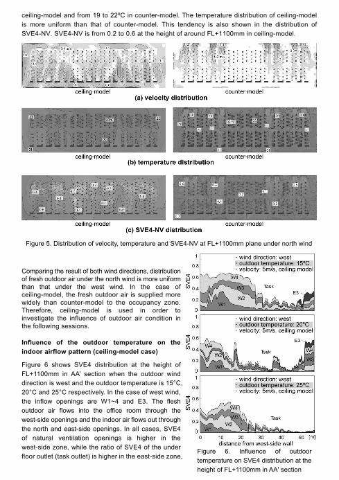
ceiling-model and from 19 to 22ºC in counter-model. The temperature distribution of ceiling-model is more uniform than that of counter-model. This tendency is also shown in the distribution of SVE4-NV. SVE4-NV is from 0.2 to 0.6 at the height of around FL+1100mm in ceiling-model.
Comparing the result of both wind directions, distribution of fresh outdoor air under the north wind is more uniform than that under the west wind. In the case of ceiling-model, the fresh outdoor air is supplied more widely than counter-model to the occupancy zone. Therefore, ceiling-model is used in order to investigate the influence of outdoor air condition in the following sessions.
Influence of the outdoor temperature on the indoor airflow pattern (ceiling-model case)
Figure 6 shows SVE4 distribution at the height of FL+1100mm in AA’ section when the outdoor wind direction is west and the outdoor temperature is 15°C, 20°C and 25°C respectively. In the case of west wind, the inflow openings are W1~4 and E3. The flesh outdoor air flows into the office room through the west-side openings and the indoor air flows out through the north and east-side openings. In all cases, SVE4 of natural ventilation openings is higher in the west-side zone, while the ratio of SVE4 of the under floor outlet (task outlet) is higher in the east-side zone,
Figure 5. Distribution of velocity, temperature and SVE4-NV at FL+1100mm plane under north wind
Figure 6. Influence of outdoor temperature on SVE4 distribution at the height of FL+1100mm in AA' section
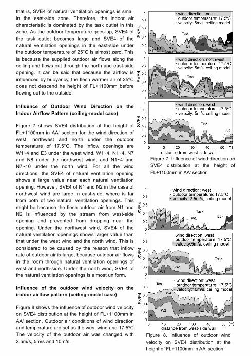
that is, SVE4 of natural ventilation openings is small in the east-side zone. Therefore, the indoor air characteristic is dominated by the task outlet in this zone. As the outdoor temperature goes up, SVE4 of the task outlet becomes large and SVE4 of the natural ventilation openings in the east-side under the outdoor temperature of 25°C is almost zero. This is because the supplied outdoor air flows along the ceiling and flows out through the north and east-side opening. It can be said that because the airflow is influenced by buoyancy, the flesh warmer air of 25ºC does not descend he height of FL+1100mm before flowing out to the outside. Influence of Outdoor Wind Direction on the Indoor Airflow Pattern (ceiling-model case)
Figure 7 shows SVE4 distribution at the height of FL+1100mm in AA’ section for the wind direction of west, northwest and north under the outdoor temperature of 17.5°C. The inflow openings are W1~4 and E3 under the west wind, W1~4, N1~4, N7 and N8 under the northwest wind, and N1~4 and N7~10 under the north wind. For all the wind directions, the SVE4 of natural ventilation opening shows a large value near each natural ventilation opening. However, SVE4 of N1 and N2 in the case of northwest wind are large in east-side, where is far from both of two natural ventilation openings. This might be because the flesh outdoor air from N1 and N2 is influenced by the stream from west-side opening and prevented from dropping near the opening. Under the northwest wind, SVE4 of the natural ventilation openings shows larger value than that under the west wind and the north wind. This is considered to be caused by the reason that inflow rate of outdoor air is large, because outdoor air flows in the room through natural ventilation openings of west and north-side. Under the north wind, SVE4 of the natural ventilation openings is almost uniform.
Influence of the outdoor wind velocity on the indoor airflow pattern (ceiling-model case)
Figure 8 shows the influence of outdoor wind velocity on SVE4 distribution at the height of FL+1100mm in AA' section. Outdoor air conditions of wind direction and temperature are set as the west wind and 17.5ºC. The velocity of the outdoor air was changed with 2.5m/s, 5m/s and 10m/s.
Figure 7. Influence of wind direction on SVE4 distribution at the height of FL+1100mm in AA' section
Figure 8. Influence of outdoor wind velocity on SVE4 distribution at the height of FL+1100mm in AA' section

As the velocity of outdoor air becomes large, SVE4 of the floor outlet becomes small and SVE4 of the natural ventilation openings becomes large. This is because the natural airflow rate increases. CONCLUSION In this paper, the influence of location of the natural ventilation openings, wind direction, velocity and outdoor temperature on the indoor airflow pattern was examined based on CFD analysis. Airflow patterns mainly cased by natural ventilation were analyzed. SVE4 is used to examine the airflow characteristics of the breathing zone of seated occupants (FL+1100mm). As a result, the following remarks were obtained.
・ Influence of location of natural ventilation openings on airflow characteristics in the room is large. The fresh outdoor air in ceiling-model case is supplied more widely to the occupancy zone than the counter-model. The domination ratio of fresh air from natural ventilation openings (SVE4-NV) in the perimeter zone in the case of counter-model is larger than that of the ceiling-model case. In the case of counter-model, however, the distribution of temperature and SVE4-NV between perimeter zone and interior zone are very large. This means that the ceiling-model is superior to counter-model from the viewpoint of distributing fresh air into the room more uniformly.
・ Under northwest wind, SVE4s of the natural ventilation openings shows larger values than west wind and north wind. This is considered to be caused by the reason that inflow rate of outdoor air is large, because outdoor air flows in the room through natural ventilation openings of west and north-side. As for the uniformity, it can be said that the fresh air can be distributed more uniformly under north wind than west or northwest wind. This is due to the aspect ratio of the room plan.
ACKNOWLEDGEMENTS Authors would like to appreciate Grant-in Aid for Scientific Research of the Ministry of Education, Culture, Sports, Science and Technology, Japan, Fundamental Research (B) 2006-No.18360274 (Representative, T. Yamanaka) that supported a part of this research.
REFERENCES 1. H. Kotani, K. Sagara, T. Yamanaka, M. Yamagiwa, T. Yamashita, S. Horikawa and T.Ushio
(2006) “Task Ambient Air Conditioning System with Natural Ventilation for High Rise Office Building (Part 2: Measurement of Natural Ventilation Rate and CFD Analysis using Measured Data)”, Proceedings of Healthy Buildings ‘06, Vol. 5, 135-140
2. E. Lim, K. Sagara, T. Yamanaka, H. Kotani, M.Yamagiwa, S. Horikawa and T. Ushio (2007) “Airflow Characteristics in Room with Hybrid Air-conditioning System of Task Air Supply and Natural Ventilation”, Proceedings of Roomvent 2007.
3. T. Ushio, K. Sagara, T. Yamanaka, H. Kotani, M. Yamagiwa, T. Yamashita and S. Horikawa (2006) “Task Ambient Air Conditioning System with Natural Ventilation for High Rise Office Buildings (Part 1: Outline of System and Thermal Environment in Working Zone)”, Proceedings of Healthy Buildings ‘06, Vol. 4, 269-274.
4. T. Yamanaka, K. Sagara, H. Kotani, M.Yamagiwa, S. Horikawa and T. Yamashita, E. Lim (2007) “Airflow Characteristics and Ventilation Effectiveness in the Office Room with Task and Ambient Air-Conditioning System using Personalized Selective Task Diffusers”, Proceedings of Roomvent 2007.

5. S. Murakami and S. Kato (1992) “ New Scales for Ventilation Efficiency and Their Application based on Numerical Simulation of Room Airflow”, International Symposium on Room Air Convection and Ventilation Effectiveness (ISRAVE), 22-38.
6. T. Ushio. S. Horikawa, K. Sagara, T. Yamanaka, H. Kotani, N. Mishima and T. Yamashita (2007) “A Study on Task Ambient Air Conditioning system with Natural Ventilation (Part 1: Outline of System and Field Measurement of Indoor Thermal Environment)”, Proceedings of Indoor Air Quality, Ventilation &Energy Conservation in Buildings (IAQVEC) 2007.


![The acute effect of budesonide/formoterol in COPD: a multi ...segmentation and computational fluid dynamics (CFD) [17]. Patient-specific assessments of the airway volume and airflow](https://img.dokumen.tips/doc/110x75/5f484cf6fbbbf70d8a07ff47/the-acute-effect-of-budesonideformoterol-in-copd-a-multi-segmentation-and.jpg)