Embed Size (px)
Citation preview
CESSNA 182 TRAINING MANUAL
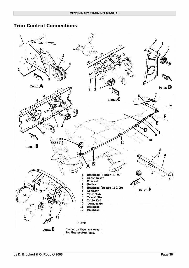
Trim Control Connections
by D. Bruckert & O. Roud © 2006 Page 36

CESSNA 182 TRAINING MANUAL
Flaps
The flaps are constructed basically the same as the ailerons with the exception ofthe balance weights and the addition of a formed sheet metal leading edge section.
The maximum deflection of the flaps is 40 degrees on all models.
Flap actuation is either by manual flap lever or electrically through a flap switch andelectric motor.
The wing flaps are of the single-slot,fowler type. Both design featuresact to further reduce the stallingspeed. The single slot modifies the directionof the airflow to maintain laminarflow longer.The fowler design increasing thesize of the wing surface area onextension.
Manual Flap
The manual flap system installed on the early models of C182 consists of .� an actuation lever;� locking push button; � mechanical linkages to the flap.
Actuation of the manual flap requires depressing the locking push button and raisingor lowering the flap to the desired position. Releasing the push button will allow theflap to lock into the next position. If you are unfamiliar with manual operation raiseand lower the flaps into each position before flight until you are comfortable withthe selections.
Mechanical flaps are directly linked to the flaps so forces required to activate aredirectly related to the air pressure on the flaps. Extending flaps close to the flaplimiting speed can be difficult, proper approach planning should be adhered to toavoid this situation.
Electric Flap
The electric flap control system is comprised of: � an electronic motor; � transmission assembly; � drive pulley, cables, and push-pull rods; � follow-up control and position indicator.
by D. Bruckert & O. Roud © 2006 Page 37

CESSNA 182 TRAINING MANUAL
Power from the motor and transmission assembly is transmitted to the flaps by thedrive pulley, cables and push-pull rods.
Electrical power to the motor is controlled by two microswitches mounted on afloating arm assembly, through a camming lever and follow-up control. They areextended or retracted by positioning the flap lever on the instrument panel to thedesired flap deflection position.
Flap Toggle Switch
The first electric flap fitted to the C182 contained a toggle switch for flap actuation.
The switch is a three position, double-throw switch, with selections for UP, OFF andDOWN. The flap position transmitter is mechanically connected to right flap drivepulley and electrically transmits position information to the flap position indicatorlocated on the instrument panel.
Selection requires holding the switch in the desired position until the settingrequired is achieved. The system is most effectively used by application of reliabletiming backed up by intermittent monitoring of the gauge.In flight at 110mph, indicated airspeed, the flaps should take approximately 9seconds to fully extend and 7 seconds to retract. On the ground with minimal airresistance, and with the engine running so the generator is supplying power, theflaps take approximately 7 seconds to extend or retract.
To select from zero to 10 degrees the toggle switch is moved to the down positionfor 3-4 seconds while intermittently monitoring the flap indicator, and then returnedto neutral when the desired. position is reached, likewise from 10 degrees to 20degrees etc.
These switches had the inherent design fault ofselecting fully up or down if the neutral positionwas not selected correctly again after selectingthe desired position.
This error invariable occurred in two ways: � Flap was selected up or down and
forgotten about (ie pilots thereafteromitted to return the switch to neutral),resulting in full travel up or down;
� After selection when returning to neutralthe selector is returned to far andinstead of neutral the flap begins travelling in the opposite direction.
Should the aircraft you are flying have a toggle switch for a flap lever remember totake particular care with selection to prevent these errors.
by D. Bruckert & O. Roud © 2006 Page 38

CESSNA 182 TRAINING MANUAL
○ rpm drop; ○ manifold pressure increase; ○ oil pressure drop, and return;
● If the engine is cold or to allow checking of each item individually,repeat the process until the rpm drops smoothly and rapidly andcorrect operation is confirmed, up to three cycles;
� Magnetos check should be done as follows:● Move ignition switch first to L and note rpm; ● Next move the switch back to BOTH to clear the other set of plugs
and regain the reference rpm; ● Then move the switch to R position, note rpm and return the switch
to BOTH position; ● Rpm drop in either L or R position should not exceed 125 rpm and
show no greater than 50 rpm differential between magnetos; � Verify proper operation of alternator, alternator control, suction system;
and correct indications (in the green) of all engine control gauges;� DI may be set to compass at this point as engine interference and
suction operation is more indicative at 1700rpm;� Reduce the engine rpm to idle to confirm idle operation on warm engine
at the correct mixture settings (approximately 500-700rpm);� Return to 1000 rpm for pre-takeoff checks.
Pre Takeoff Vital Actions
The flight manual provides the “minimum required actions” before takeoff, generallythere are some additional operational items to check. Many flight schools oroperators will have their own check lists and/or acronyms for the pre take-offchecks. Acronyms are highly recommended for single pilot operations. One of themost popular acronyms for pre-takeoff checks is as follows:
Too Test controls and trims;Many Mixture set for takeoff*;
Magnetos on both;Pilots Pitch full fine;Go Gills (cowl flaps) open and Gyros uncaged and set (as applicable) Fly Fuel contents checked on correct tank, primer locked, fuel pump-off
(C182S,T); Flaps set for takeoff;
In Instruments, panel check from right to left, DI aligned with compass, time check;
Heaven Hatches and harnesses secure;Early Electrics circuit breakers checked, lights, switches correct position,
systems (Autopilot/GPS/Fuel management) set for departure.
*For normally aspirated engines Cessna recommends leaning above 5000ftpressure altitude in the latest models, and earlier models recommend 3000ft. Basedon extensive experience at high density altitudes, these altitudes are far too high if
by D. Bruckert & O. Roud © 2006 Page 104

CESSNA 182 TRAINING MANUAL
combined with a high outside temperature, and significant loss of performance willresult. Takeoff fuel flow on a fuel injected engines must closely match therecommended maximum power fuel flow placard, provided by Cessna in theexpanded performance section. This fuel flow placard provides incrementalreductions from SL in 2000ft steps, which often will require leaning to achieve. Withthis in mind, it is recommended that carburettor engines should be leaned above3000ft density altitude. Full rich operations above this will result in significant lossof performance. Where not specified altitudes should be taken to mean densityaltitude, since engine performance is dependant on the prevailing density notpressure.
Takeoff
Takeoff is always carried out under full power with the heels on the floor to avoidaccidentally using the toe brakes. Unless on gravel or with traffic around, it isalways good airmanship to line up straight on the runway centreline, stop andcomplete final line up checks.
The following items should be selected and checked on line up, (these also have ahelpful acronym):
REmember Runway clear from obstruction; Engine parameters checked;
What Windsock aligned, controls into wind;To Transponder on ALT;Do DI aligned with compass and indicating runway direction;Last Lights strobe and landing lights.
It is important to check full-throttle engine operation early in the takeoff run.Although setting the power too quickly will result in possible rich cut, rough running,overrun of the rpm red line while the CSU reacts and piston damage due to rapidacceleration. When the runway surface is clear static or partial static powerapplications may be made.
Any sign of rough engine operation or sluggish engine acceleration or less thanexpected takeoff power is cause to discontinue the takeoff.
The engine should run smoothly and with constant redline static rpm (2400 or 2600depending on model) and manifold indicating within 1-2 inches of ambient pressure.
When taking off from gravel runways, a rolling takeoff should be used, as the gravelwill be blown back of the propeller rather than pulled into it. The throttle should beadvanced slowly, allowing the aeroplane to start rolling before high rpm isdeveloped to minimize damage to the propeller and engine.
by D. Bruckert & O. Roud © 2006 Page 105

CESSNA 182 TRAINING MANUAL
After full throttle is applied, adjust the throttle friction lock clockwise to prevent thethrottle from creeping back. Keep one hand on the throttle when possible untilreaching a safe altitude of 500-1000ft AGL
Takeoff and Maximum Power Setting for Fuel Injected Engines (C182S and C182T)
A normally aspirated fuel injected enginewill typically have a maximum powerversus fuel flow placard, like the one fromthe C182T illustrated opposite.
The takeoff procedure for a normallyaspirated engine from the Cessna POHstipulates “the mixture should be leaned togive maximum rpm at full throttle, thisshould provide a fuel flow to closely matchthe placard” and further for a maximumpower climb “for maximum power, the fuel flow should be set in accordance withthe placard, this is a minimum required fuel flow”. For normal operations, theengine fuel flow may be set at run-up rpm for departure, thereafter the fuel flowchecked against the maximum power placard. For maximum performance,however, a full power setting will not only ensure the mixture is set correctly, butalso enable a full power engine check prior to departure.
In the turbo engine, the recommended fuel flow and power setting do not changewith altitude, since the pressure developed in the manifold is the same at altitudeas it is at sea level up to the maximum certified take-off altitude. The mixture musttherefore be set fully rich for takeoff, and the fuel flow checked against thatspecified in the flight manual. The recommended takeoff power for the turbo-charged T182T is 32” manifold and 24GPH fuel flow.
Wing Flaps Setting for Takeoff
Takeoff may be made with 0, 10, or 20 degrees of flap. Using the flaps for takeoffwill shorten ground roll but will reduce climb performance of aircraft. During testing, it is established which flap settings will be most favourable and theassociated performance is tabulated.
Using 20º wing flaps on C182 reduces the total takeoff distance to 50ft obstacleclearance considerable, however if there is rising terrain after the 50ft point climbperformance should be considered. Use of flap on soft or rough surfaces will assist with reducing the frictional dragconsiderably.Flap deflections greater than 20º are not approved for takeoff.
by D. Bruckert & O. Roud © 2006 Page 106

CESSNA 182 TRAINING MANUAL
If flaps are used for takeoff, they should not be retracted below 300ft AGL and notbefore a safe flap retraction speed has been reached. On flap retraction the aircraftloses lift and with insufficient speed may sink down. The AFM does not specify a flapretraction speed, 80mph is recommended.
Short Field Takeoff
For the minimum takeoff distance to clear a 50ft obstacle the AFM Recommendedshort field take off procedure specifies: � Wing flaps 20 degrees� Apply full throttle against brakes*, 2600rpm� Elevator should be slightly low, lift off early� Maintain 55kts / 65**mph until obstacles are cleared � Retract flaps once obstacles are cleared (and after safe retraction speed is
reached )
* If power is applied after brake release increase distance by the distance taken toapply full power.
**Note on takeoff safety speedsVt/o or V2 the takeoff target speed at 50ft according to internationalrecommendation should not be less than 1.2 Vs, or 1.2 x the indicated stall speed inthe applicable configuration.
The indicated stall speed is marked by the bottom of the green or white arcdepending on the configuration. These are 67 and 60mph respectively. Taking 60mph stall speed with full flap, 60x1.2 = 72mph, however therecommended short field speed for takeoff in the POH of many models is 61mphwith 20 degrees flap.
It can be assumed from the calibrated airspeed tables that due to errors from theangle and configuration this speed is safely achievable if we require maximumperformance, however we know better in aviation than to assume. It is advised to add a 5kt margin to the recommended speed, but not less than thebottom of the green arc as a minimum target speed for takeoff to compensate forwind, turbulence and performance deviations. Performance requiring more accuracy than this is probably operating withoutadequate safety margins on field length and should not be considered for normaloperations.
Takeoff Performance Graphs
To obtain the correct figures for takeoff for your aircraft model, configuration, andweight, consult the performance graphs in the POH from the aircraft you are flying. Any deviation from the recommended procedure should be expected to give adecrease in performance.
by D. Bruckert & O. Roud © 2006 Page 107