Embed Size (px)
Citation preview

Page 1
CES322417
Computational modeling linear structure with Civil 3D, Revit & Dynamo CivilConnection Package Michel Beliën Royal HaskoningDHV Rob Zutt Royal HaskoningDHV
Class Description In an early design phase, a parametric Civil 3D model of a tunnel was setup using the subassembly composer. Where Civil 3D is strong in linear oriented design, Revit is strong in placing object-oriented elements. With the CivilConnection package for Dynamo it is possible to setup and change a Revit model based on the corridor and feature lines from the civil 3D model. Where the Civil 3D Model follows the curved alignment as much as possible, it is necessary to work towards a more implementation-ready model in Revit during designing. We constantly look for optimizations. Without computational modeling, quickly processing new design insights is a time-consuming job and no longer of this time
Learning Objectives • Creating a Civil 3D model with the subassembly composer that is ready for
applying with the CivilConnection Package for Dynamo • Use dynamo to read your Civil 3D model • Build your Revit Model based on the Civil 3D model and information • Use the power of Civil 3D and Revit together

Page 2
Speaker(s) Michel Beliën Revit & BIM specialist Royal HaskoningDHV I am a structural engineer who has been focusing for many years on managing, standardizing and optimizing design software to enable us to be more efficient, effective and profitable in our way working. In recent years I have been made responsible for implementations and developments of applications that need to directly interface with Revit within Royal HaskoningDHV. Therefore we have started in the summer of 2016 looking for opportunities to automate design challenges by either parametric or computational design. I have a keen interest in staying up to date to latest industry trends and I investigate new technologies for their potential usage within the company. I am also actively involved in a Infrastructure User group in the Netherlands with many progressive minds in our field. Rob Zutt Design leader - Civil 3D expert Royal HaskoningDHV Rob is a design leader and responsible for the design of roads for many different clients; managing of designers, exchange between professional disciplines and assistant project leader. In recent years Rob has been, as one of the pioneers in Royal HaskoningDHV, mainly engaged in 3D road design, visualisations, scripting and the development of innovative methods. These new methods enable us to support our customers efficiently and visually in their development process, so that they can make informed choices. After his study Civil Engineering in 2002 Rob started as a draftsman and from that direction he participated in all facets of civil engineering (draftsman, designer, contract writer, assistant project manager). Rob is constantly looking for ways to simplify working methods, to do things faster and to make them transparent for everyone. This keeps people involved and then we are able to make beautiful things together!

Page 3
Table of Contents Class Description .......................................................................................................................... 1
Speaker(s) .................................................................................................................................... 2
Introduction ................................................................................................................................... 5
Project ........................................................................................................................................... 5
Access Ramps Tunnel ........................................................................................................... 5
Tender Design – Civil 3D ....................................................................................................... 6
Prelimenary Design ............................................................................................................... 8
Final Design ......................................................................................................................... 10
Preparation Final Design (FD) .................................................................................................... 13
Project Approach FD ........................................................................................................... 13
Trade off Matrix .................................................................................................................... 14
Workflow .............................................................................................................................. 15
Civil 3D Vs Revit .................................................................................................................. 16
Setting up the Civil 3D model ...................................................................................................... 17
Corridor modeling basics ........................................................................................................................ 17
The Subassembly .................................................................................................................................... 18
Adding points to the Subassembly ......................................................................................................... 19
Adding points to the corridor ................................................................................................ 19
Dynamo for Revit ........................................................................................................................ 21
CivilConnection Package ............................................................................................................ 24
CivilConnection Example Nodes ......................................................................................... 26
Work process .............................................................................................................................. 29
C3D | Extract Corridor Solid ................................................................................................ 29
C3D | Property Sets ............................................................................................................. 35
Dynamo | Extract Corridor Solid .......................................................................................... 36
Revit | Link the IFC .............................................................................................................. 38
Revit | C3D Shared Parameters ......................................................................................... 39
Revit | Parameter RegionName .......................................................................................... 40
Revit | Parameter CodeName ............................................................................................. 42
Civil 3D “IFC” into Revit .............................................................................................................. 44

Page 4
.................................................................................................................................................... 44
Revit Project Model ..................................................................................................................... 45
Model Elements Construction Pit ......................................................................................... 45
Model Elements Access ramps ........................................................................................... 49
Specials ............................................................................................................................... 51
Current Situation ......................................................................................................................... 52
Advantages CivilConnection ....................................................................................................... 53
Focus Areas CivilConnection ...................................................................................................... 53
Skills ............................................................................................................................................ 54
About Royal HaskoningDHV ....................................................................................................... 55

Page 5
Introduction This document is the handout that provides context and more in-depth information for the presentation.
Figure 1: Connection Civil 3D Dynamo CivilConnection Package Revit
Project Access Ramps Tunnel Royal HaskoningDHV responsible for the design off the access ramps of the tunnel
Figure 2: Situation access ramps North & south

Page 6
Tender Design – Civil 3D Tender design is done with Civil 3D
Figure 3: Civil 3D Tender drawing North
Figure 4: Civil 3D Tender drawing South

Page 7
Figure 5: Civil 3D Tender section access ramp

Page 8
Prelimenary Design In the preliminary design the Civil 3D model is still the basic model added with 2D details to get a good overview of the design principles and all the needed tolerances.
Figure 6: AutoCad PD Detail
Figure 7: AutoCad PD Details

Page 9
Tunnel – half deepend (not in the scope) • Reinforced underwater concrete with screwed-combi piles • Temporary sheet piles without anchors • Without structural floor • Fillings (Variable) • Emergency tube • 89 Segments x 25m (2,225 Km)
Access Ramps
• Underwater concrete with screwed-combi piles • Permanent Sheet piles with anchors • Structural Floor • Fillings (Variable) • Central emergency reservation • Cladding walls • 16 + 13 Segments (North = 400m+ South = 325m)

Page 10
Final Design For the final design a Revit model is required (by the BIM managers) for all civil structures. With the BIM Execution Plan the development for the final design is defined. Preperation and a good project approach good be defined for creating the Final Design Models
Model agreements • Design shouled be done in 3D! • All Structures with Revit • Detailed Revit Project manual
o Template o Project Basepoint / Shared Coordinates o File Name convention, include for families o View templates o Filters o Sheets / revision o (Shared) Parameters o Legends o Object styles & Subcategories (NLCS NL CAD Standards infrastructures) o Materials o Assembly codes o Cad Link / Imports
o o Exports settings
• DWG • NWC • IFC
o Project Logbook

Page 11
Model Division & Components • Models North
• Pit Model • Access Ramp Model • Specials, Pomp Room
• Models South • Pit Model • Access Ramp Model
Figure 8: 3D overview construction pit
Figure 9: 3D access ramp north

Page 12
Classification
Every element should be logically coded by: • Assembly Code • Location properties
• Segment Numbers • Main Road (Left, Right) • Side (In- or ex- terroir)
Figure 10: Classification

Page 13
Preparation Final Design (FD) Project Approach FD
• Continuity Tender Model • Digital Engineering
o Parametric design o Scripting o Applications
Civil 3D Revit Dynamo
• CivilConnection Package
Figure 11: brainstorm session

Page 14
Trade off Matrix
Figure 12: trade off matrix

Page 15
Workflow
• MX (Road Design0 • Design Parameters • Design Changes • Aplications
o Civil 3D o Dynamo (CivilConnection) o Revit (Civil Structures)
• Document management Engineering Data (WIP) o Vault o BIM 360
- Figure 13: workflow scheme

Page 16
Civil 3D Vs Revit Linear Curved vs Straight Segments Corridor segment 25 m vs Discrete objects, Elements 2,5m/ 5m
Page 17
Setting up the Civil 3D model Civil 3D is the common Application for linear orientated infrastructure projects. Civil 3D has multiple options for 3d modeling. For this class we mainly will look at the Corridor modeling part of Autodesk Civil 3D. When wanting to use the Dynamo CivilConnection package, the Civil 3D model needs to be set up correctly. This chapter will explain how to code your model so it can be read in Dynamo. It will also give a short introduction to the Civil 3D basics that are needed to setup the Civil 3D model.
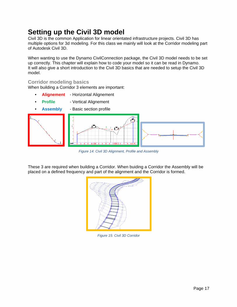
Corridor modeling basics When building a Corridor 3 elements are important:
• Alignement - Horizontal Alignement • Profile - Vertical Alignement • Assembly - Basic section profile
Figure 14: Civil 3D Alignment, Profile and Assembly
These 3 are required when building a Corridor. When buiding a Corridor the Assembly will be placed on a defined frequency and part of the alignment and the Corridor is formed.
Figure 15: Civil 3D Corridor

Page 18
The Subassembly An important part of the assembly is the subassembly. The subassembly defines which parts of the Corridor are generated, by using Point-, Link- and Shapecodes.
Figure 16: Civil 3D Subassembly codes
The Points from the subassembly define the Corridor featurelines. In the Corridor, the Points with the same code are connected. This is the Corridor FeatureLine.
Figure 17: Civil 3D Corridor featureline connection
The Autodesk out-of-the-box subassemblies can be used and edited to add codes to subassemblies. And there is also a possibility to create custom subassemblies in the Subassembly Composer. The Autodesk® Subassembly Composer provides an interface for composing and modifying complex subassemblies, without a need for programming. For this case a custom subassembly was created in the subassembly composer.
Figure 18: Subassembly composer

Page 19
Adding points to the Subassembly The point codes are added to a subassembly in the subassembly composer or you can add it to the pre-defined fields in the properties window in Civil 3D.
Figure 19: Adding Point Codes to the Subassembly composer
Figure 20: Adding Point Codes to the Subassembly in Civil 3D
Adding points to the corridor When the point codes are filled in you need to check if they are also added to the corridor. The Code Set Style the Corridor uses, must contain the codes you added to the subassembly. Go to the Settings tab, General \ Multipurpose Styles \ Codes Set Styles and right-click to edit the Code Set Style you want to change.
Figure 21: Adding Point Codes to the Subassembly in Civil 3D

Page 20
With import codes, you can select your subassembly to add the codes to the Code Style Set used for the Corridor.
.
Figure 22: Import Codes to the Code Set Style
Now the codes are added to the Corridor and recognized when reading it into Dynamo via the Civil Connection Package. The Corridor.GetFeaturelinesByCode can be used to read the Corridor Feature lines.
Figure 23: Dynamo Node Corridor.GetFeaturelineByCode
The node will look at the PointCodes of the specific featureline and will then use it.

Page 21
Dynamo for Revit To make the dynamo scripts readable for other users we made some agreements
Dynamo legend
Group nodes by topics Give general information about the script Needed instructions Known issues Used packages
Figure 24: Dynamo Legend
Group colors In the legend we use a different color for used nodes from a Dynamo packages. This red color isn’t available in the standard group colors of Dynamo
Figure 25: standard Dynamo group colors
To change the group color we are using a Dynamo add-in named Beyond Dynamo

Page 22
Beyond Dynamo
Figure 26: about Beyond Dynamo
https://github.com/JoelvanHerwaarden/BeyondDynamo2.X
Figure 27: Change group color Beyond Dynamo

Page 23
Parts By Component
Creating a group with 2 note nodes and a big (Font Size 96) clear title name above the relevant nodes for the components will help to order your script
Figure 28: parts by component
Rename Groups and Nodes
Renaming the group name and also the node name with a clear description will help to make the script readable for others Rename the node <OriginalName><Space><Vertical line><Space><Clear Description>
Figure 29: rename string

Page 24
CivilConnection Package CivilConnection is a package for Dynamo for Revit that connects Revit and Civil 3D. The package enables prototyping and interoperability between the two modeling environments. Autodesk Consulting has developed this package to support the linear Structure Model Authoring workflow. Linear structure Workflow Guide.pdf Or …\AppData\Roaming\Dynamo\Dynamo Revit\2.2\packages\CivilConnection2020\extra
Figure 30: Linear Structure Workflow guide

Page 25
The Dynamo CivilConnection package can be installed through Packages > Search for a package.. in Dynamo for Revit.
Figure 31: CivilConnection Package install
Figure 32: CivilConnection github
https://github.com/Autodesk/civilconnection
CivilPython Installation CivilPython is also needed to let CivilConnection work properly. Make sure the CivilPython.bundle folder is copied to. C:\ProgramData\Autodesk\ApplicationPlugins

Page 26
CivilConnection Example Nodes CivilApplication Get the DocumentName from the Civil 3D Application
Figure 33: CivilConnection nodes; CivilApplication and GetDocumentByName
CivilDocument From the Civil DocumentName read the alignements and Corridors
Figure 34: CivilDocument get…

Page 27
Corridor From the corridors get the Codes and Featurelines (By Station)
Figure 35: CivilConnection, corridor.Get..
Warning: about Geometry Working Range see Linear Structures Workflow Guide …\AppData\Roaming\Dynamo\Dynamo Revit\2.2\packages\CivilConnection2020\extra
Featureline From the Featurelines get the curves or points on the featureline by station.
Figure 36: CivilConnection, Featureline

Page 28
RevitUtils with the curves and points create Revit Elements and assign them to featurelines
Figure 37: RevitUtils, assign featureline
In Revit there are ADSK Parameters created by CivilConnection with Civil 3D data
Figure 38: ADSK parameters
Page 29
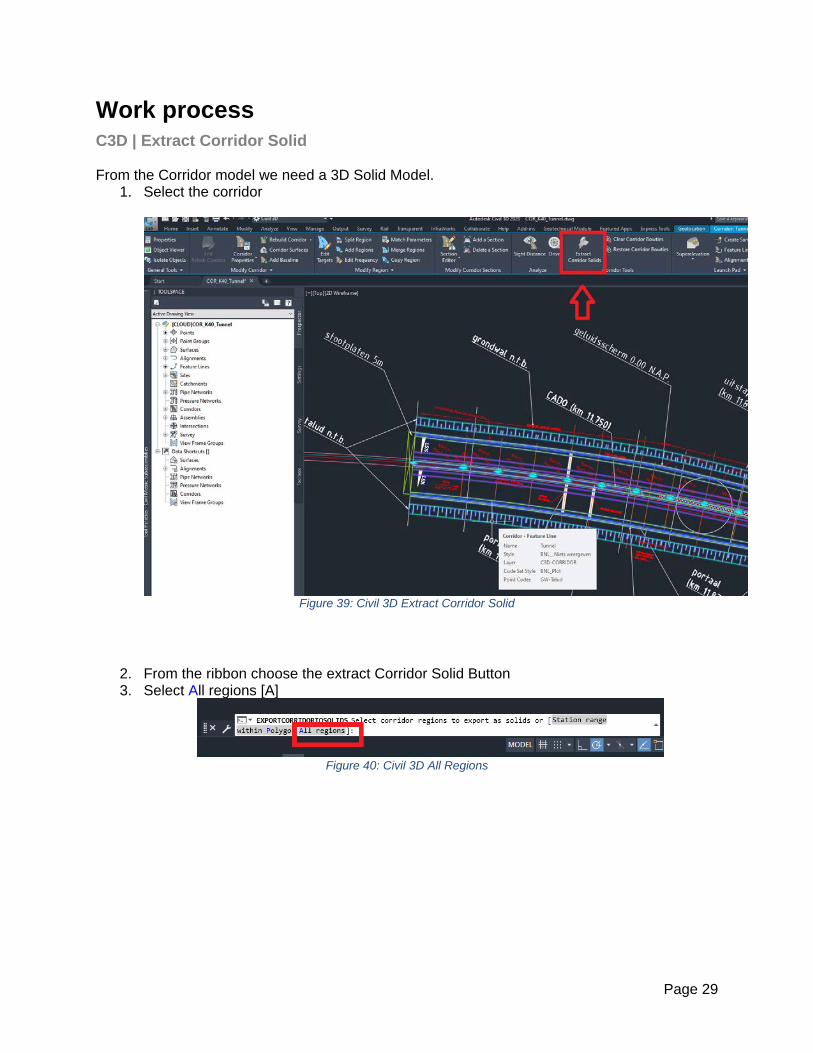
Work process C3D | Extract Corridor Solid From the Corridor model we need a 3D Solid Model.
1. Select the corridor
Figure 39: Civil 3D Extract Corridor Solid
2. From the ribbon choose the extract Corridor Solid Button 3. Select All regions [A]
Figure 40: Civil 3D All Regions

Page 30
4. The extract Corridor Solids Dialog box is shown
Figure 41: Civil 3D Corridor Solid Dialog box
5. Codes to extract | Make your selection a. Regions
Figure 42: Civil 3D Codes to extract

Page 31
b. No Link (turn them off)
Figure 43: Civil 3D Corridor Solid Dialog box unselect Link
c. Avoid White Colors, Change them in Color 254
Figure 44: Civil 3D avoid white colors

Page 32
d. Turn off unnecessary Shape
Figure 45: Civil 3D Corridor Solid Dialog box turn off unnecessary shapes
e. After finishing your selection Click next
Figure 46: Civil 3D Corridor Solid Dialog box next

Page 33
f. Property Data | as they are and click Next
Figure 47: Civil 3D Solid Property data
g. Output Option | 1. add to a new drawing; 2.select output file
Figure 48: Civil 3D Solid output options
h. 1.Correct folder; 2.file name (Sol = Solid); 3.save
Figure 49: Civil 3D Solid file name

Page 34
i. Extract Solids
Figure 50: Civil 3D extract Solids
6. Open the Solid model file in C3D
Figure 51: Civil 3D Solid model

Page 35
C3D | Property Sets Every solid in C3D has a property sets, with Corridor Model Information & Corridor Shape Information.

Page 36
Dynamo | Extract Corridor Solid
1. Open Dynamo file CC_Export CivilSolids to IFC 2. Fill in CivilDocument and browse to path where your Revit file is saved
Figure 52: Dynamo CivilConnection Export CivilSolid to IFC
3. Run Dynamo script

Page 37
4. Dynamo export a IFC from Civil 3D
Figure 53: IFC Export Progress (In C3D)
Figure 54: IFCEXPORT
5. The IFC is named as your Civil 3D file with the suffix _Origin 6. Also a log file is created
Figure 55: IFC solid file

Page 38
Revit | Link the IFC
1. In Revit Link the IFC
Figure 56: Revit Link IFC
2. The IFC will appear in Revit
3. Figure 57: IFC in Revit

Page 39
4. There are also new files created
Figure 58: Origin.ifc files
Revit | C3D Shared Parameters With linking the IFC in Revit the properties from C3D are visible.
Figure 59: C3D properties in Revit
These are stored in a shared parameter file and can be add in Revit as a Project Parameter to use them for filtering your object.

Page 40
Revit | Parameter RegionName add the project parameter from the shared parameter RegionName(Corridor Model Information) to create filters by RegionNames and play with the Region visibilities.
Figure 60: add shared parameter in Revit
Figure 61: create region filters in Revit

Page 41
Figure 62: region visibility in Revit

Page 42
Revit | Parameter CodeName When creating sections, the linked ifc model doesn’t have the correct pattern yet.
Figure 63: Revit section without patterns
To make the section useable we can use the property Codename from the C3D model by creating a Project Parameter of CodeName(Corridor Shape Information) Shared Parameter.
Figure 64: Add CodeName Parameter

Page 43
Creating filters with overrides will give a better section
Figure 65: filter CodeName parameter
Figure 66: Filter overrides

Page 44
Civil 3D “IFC” into Revit
With the IFC linked into Revit we do not have a Specific Revit model We use the IFC as a reference for modelling the revit object

Page 45
Revit Project Model
Model Elements Construction Pit
Capping Beam • Structural Framing • Featureline code • Variabele distance edge asphalt • Slope ramp (determine horizontal distance cladding wall) • Dimensions elements
• Capping beam (1000x1200) 1100x1200 • Barriers • Cladding wall (angle 0-20° 40m)
• Tolerances

Page 46
Sheet Piles Structural Columns with voids.
Piles Structural Columns Floors
Generic Model Adaptive (4points)
• Concrete structural floor • Plinth along sheet piles • Filling • Gravel • Underwater concrete (Basic)
•

Page 47
Cutting Sheet piles with Floors
Figure 67: Python scripting for cutting sheet piles with floors

Page 48
Result scripting construction Pit North

Page 49
Model Elements Access ramps
Figure 68: overview model elements access ramp
Cladding walls 4 Point Adaptive Component Fillings Generic Model (external Family) Asphalt Generic Model (external Family) Barriers Structural Framing Guide rails 2 Point Adaptive Component Concrete Plinth Wall by Profile

Page 50
Result Scripting Access ramp North

Page 51
Specials Tunnel Portal
Figure 69: 3D section view Tunnel portal
Pomp Room
Figure 70: 3D Pomp Room
Traffic barrier area
Figure 71: 3D section traffic barrier area

Page 52
Current Situation North
South

Page 53
Advantages CivilConnection
• Best of 2 worlds C3D (Linear) & Revit (discrete objects) • Civil 3D model long useable during design
o Alignment changes o Featurelines o Codenames (subassembly)
• Lineare C3D object bi-directional with revit model • Revit objects zijn coordinated and dynamic connected with Civil 3D • Changing Alignement as long as Possible. • Placed objects can be convert to C3D.
Focus Areas CivilConnection • Dynamo knowledge • Clean Civil 3D model (Dynamo is consequent, roundups !) • Reading Corridor Featurelines Codes names, “slow” {188 x (16+89+13)= 22,184 } • Not yet many project experience. • C3D, IFC and Revit in same directorystructuur!
o Vault, not with Revit Collaboration o BIM 360, not yet for C3D! (2020 Beta 2) o IFC possible with Desktop connector

Page 54
Skills Main skills
Software skills Revit Engineer Civil 3D Engineer

Page 55
About Royal HaskoningDHV Royal HaskoningDHV is an independent international engineering and project management consultancy leading the way in sustainable development and innovation. An organization with 6000 employees, 100 permanent offices in more than 30 countries committed to enhance society together. Royal HaskoningDHV professionals deliver services in the fields of aviation, buildings, energy, industry, infrastructure, maritime, mining, transport, urban and rural development and water. The organization focuses on delivering added value for the clients while at the same time addressing the challenges that societies are facing. These include the growing world population and the consequences for towns and cities; the demand for clean drinking water, water security and water safety; pressures on traffic and transport; resource availability and demand for energy and waste issues facing industry. By showing leadership in sustainable development and innovation, together with the clients, Royal HaskoningDHV is becoming part of the solution to a more sustainable society now and into the future. The organization is driving positive change through innovation and technology, helping clients use resources more efficiently and creating solutions which connect with people to make their lives easier, happier and safer. Connecting lives is our history and our future. We are connected through a passion to work on projects that matter and to engineer solutions for our clients that go beyond the original brief. We are connected through work that is enhancing society, contributing to a more sustainable future for our children and our children’s children.
Royal HaskoningDHV Corporate video www.royalhaskoningdhv.com Enhancing Society Together