Embed Size (px)
Citation preview

© 2016 by Robert Taylor, Titan Industries, and Lockheed Martin Corporation (PIRA #AER201607010)
1
Certification Strategy for Additively Manufactured
Structural Fittings
Robert M. Taylor 1
University of Texas at Arlington, Arlington, TX, 76019
Joe Manzo 2
Titan Industries, Tempe, AZ 85281
Lori Flansburg 3
Lockheed Martin Aeronautics, Marietta, GA 30063
While many opportunities exist to leverage additive manufacturing technology for design
improvement, structural component fabrication with additive technologies must
demonstrate reliability and integrity sufficient to satisfy certification authorities in order to
open the door for use on flight vehicles. This certification challenge is formidable given the
large number of process parameters, the magnitude of process variability, and the sensitivity
of mechanical properties to these process variables. Historical precedent in certification of
other materials and processes, such as composites, castings, and welded joints that exhibit
sensitivity to parameters, geometry, and operator skill provides a guide to certification of
additive structures. This paper discusses certification processes for these components and
applies lessons and methods from them to develop a strategy to certify an additively
manufactured structural fitting component.
I. Introduction
Additive manufacturing (AM) has the potential to revolutionize design of many types of structural components if
the challenge of designing and fabricating components with reliability sufficient for certification can be met.
Opportunities to leverage AM processes for structural improvement include low volume production, aging
component replacement, piece part reduction, multi-functionality, increased complexity, and performance
improvement through physics-based design optimization free from many conventional manufacturing constraints.
Despite these opportunities, the certification challenge is formidable and must address reliability throughout the
component life cycle through material integrity, manufacturing process integrity, design and analysis method
integrity, and robust testing and inspection built on a foundation of statistics. Knowledge, methods, and tools in
each of these domains must be correlated and calibrated against robust testing at multiple scales. As with other
manufacturing processes, a comprehensive building block test program, tailored to AM process specifics, can be
effective in building reliability by developing statistical confidence through testing, analysis correlation, and
inspection at various levels of structural complexity, starting with small coupon specimens and progressing through
structural elements, components and full-scale products. Only through such rigorous, structured investigation of
manufacturing capability will reliability of AM structures improve sufficiently to enable widespread application of
this promising technology.
This need for rigor and structured methodology to ensure reliability must be balanced with the unique demands
and opportunities of additive manufacturing. For example, if additive manufacturing is to be used for low-volume
production of a component, execution of a full building block test program with the thousands of coupons typical for
composite structures is not economically feasible. Another consideration is the effect of increased geometric
complexity on the validity of assumptions used in conventional analysis methods widely used to write margins-of-
1 Professor in Practice, University of Texas at Arlington
2 CEO, Titan Industries
3 Principal Engineer, Lockheed Martin Aeronautics
1985
Solid Freeform Fabrication 2016: Proceedings of the 26th Annual InternationalSolid Freeform Fabrication Symposium – An Additive Manufacturing Conference
Solid Freeform Fabrication 2016: Proceedings of the 27th Annual International
© 2016 by Robert Taylor, Titan Industries, and Lockheed Martin Corporation (PIRA #AER201607010)
2
safety for aerospace structures. Still another consideration is the ability of AM materials to equivalently replace
wrought materials in a replacement of an aging component that was certified potentially many decades ago. Yet in
all of these considerations, the structural reliability requirement stands and must be addressed effectively and
economically.
Developing methods to ensure reliability in additive structures requires industry and researchers to examine
sources of variability and determine methods to demonstrate it is within acceptable limits at all size scales across
fabrication processes, material properties, design and analysis methods, and inspection capabilities. Fabrication
processes must be demonstrated to be stable and controlled with process specifications that yield consistent
component performance and enable supplier qualification. Specifications for monitoring and control of raw
materials must ensure material integrity during handling and storage while specifying required environmental
control. Specifications for monitoring and control of process parameters must call on well-characterized parameter
sensitivities and specify variances and control limits to communicate acceptable settings and ranges. With these
specifications, processes must be fixed to ensure consistency and repeatability from part-to-part, location-to-
location, and supplier-to-supplier.
To establish design and manufacturing process reliability, fabricated components must be inspected, tested, and
evaluated to verify that as-built properties and part performance matches predictions. Historically, this has been
accomplished through a combination of non-destructive inspection (NDI), destructive testing, and part-specific
acceptance testing using NDI and traveler or witness material to verify process control. AM processes challenge
these standard methods due to the increased sensitivity to and interaction among process parameters. For example,
since AM material properties exhibit sensitivity to geometry (e.g. wall thickness) and interlayer time interval effects
due to size effects, witness coupons printed in the same build must be carefully planned to ensure they exhibit
similar geometric and build characteristics representative of the fabricated part.
Current structural design practice ensures reliability through reliance on well-characterized, statistically-based
mechanical properties developed through a robust coupon test program that incorporates manufacturing process
capability. These allowable property values ensure designs account for material and process variability within
acceptable statistical ranges and confidence levels. AM challenges current design practice again due to the
increased sensitivity to and interaction among process parameters and their interaction with design configuration.
Because properties can vary significantly due to size variation, surface roughness, and porosity, all of which exhibit
strong sensitivity to process parameters, material allowables must be developed with respect to significant process
parameters.
Finally, structural reliability requires predictable structural performance determined using accessible, verified,
and validated design tools. Many AM material and process characteristics challenge assumptions used in standard
analysis methods and tools used to develop margins-of safety for aerospace structural components. For example,
some components use plastic bending analysis to allow loading to develop stresses in the material plastic range. AM
part behavior must be characterized to determine if build orientation effects on anisotropy, surface roughness, and
porosity can be accommodated in the underlying assumptions that form the basis of plastic strain redistribution in
plastic bending analysis.
Of course, industry teams can continue to pursue a part-specific certification process that tests the design,
material, and fabrication process against all criteria, loads, and parameters without verified and validated allowables,
design methods, and inspection process. This part-specific process is unique to individual parts, expensive, and
prohibitive to broader application of AM to realize its potential benefits. Instead, a lean, tailored building block
approach is needed in order to provide a comprehensive, standardized strategy that is accepted by certifying
authorities to enable AM as a viable manufacturing option. Indeed, researchers at the United States Air Force
Research Lab highlighted the many qualification challenges for additive structures but concluded that despite these
challenges, the main barriers to broader application of AM are cost, performance, and schedule.1 A standardized,
comprehensive strategy is need to improve the cost, performance, and schedule outlook.
This paper discusses certification processes for conventionally manufactured components and applies lessons
and methods from them to develop a strategy to certify an additively manufactured structural fitting component.
First, conventional structural certification is discussed as a basis for AM processes against those for wrought metal,
composites, casting, and welding. Next, a strategy is proposed and discussed for AM structural certification,
including building block for AM, coupon testing and inspection, component testing and inspection, and analysis
method development, calibration, and verification. Finally, this AM certification strategy is applied to design of a
structural fitting to illustrate implementation and identify current capability gaps.
1986

© 2016 by Robert Taylor, Titan Industries, and Lockheed Martin Corporation (PIRA #AER201607010)
3
II. Conventional Structural Certification
A review of certification processes for structures manufactured using conventional (non-AM) manufacturing
processes illustrates the various paths that are used to ensure structural reliability in aerospace vehicles. First, an
overview of structural certification processes and requirements is given to establish context. Next, certification
process details specific to components fabricated from different conventional processes are given. These processes
include wrought metals, composite materials, castings, weldments, and powder metallurgy. In particular, the last
four processes highlight how reliability is demonstrated in structures where there is high sensitivity of mechanical
properties to process parameters and controls.
A. Structural Certification Processes and Requirements
Before an aircraft model can be sold and delivered for service, it must be certified by government regulators that
it meets the government specifications, as applied to the specific aircraft program. Part of the requirements that must
be fulfilled for certification is to present proof of compliance to the requirements to the certifying agency. This is
required for all systems on the aircraft, but this discussion is limited to the aircraft structure. The demonstration
artifacts that must be presented for structural integrity to obtain certification include the design drawings, analysis
and correlated test results. At the end of this process, if the certifying agency is satisfied, the aircraft is certified safe
to fly and can then be sold and flown.
Typical certifying agencies are the Federal Aviation Administration for commercial aircraft and the U.S. Air
Force, U.S. Navy or U.S. Army, depending on the military aircraft. Each agency has its own regulatory documents
governing structural integrity and airworthiness such as 14 CFR Part 25 for Transport Category Aircraft2 for the
FAA. Additional guidance for FAA-certified aircraft and rotorcraft exists in other parts of the code of federal
regulations. The Joint Services Specification Guide (JSSG-2006)3 provides the requirements for the Air Force and
Navy. Additional Air Force requirements for the Aircraft Structural Integrity Program (ASIP) are called out in Mil-
STD-1530C4 and AWB-1015
5.
Both the airworthiness requirements of 14 CFR Part 25 and the ASIP program require the classification of parts
based on criticality. Table 1 provides a summary of the parts classification categories.
Table 1 Summary of Parts Classification Requirements
Military Certification (JSSG-2006 and Mil-STD-1530C) Civilian Certification (FAR-25, et. al.)
Fracture Critical I or II (FC) – Highly critical, single
load path safety of flight parts Principal structural elements (PSE) and Detail Design
Points (DDP) – Structural parts, the failure of which
could result in catastrophic failure of the airplane.
Also called “Critical Part.”
Durability Critical (DC) or Maintenance Critical (MC)
– Structural parts affecting the economic life of the
aircraft
Normal Controls – All remaining structural parts
Aircraft typically use strain-based certification. This is also sometimes referred to as the Test-Model-Analyze-
Test Correlation approach and can be described as
Test – obtain statistically based basic material properties from a stable, documented process
Model – mathematically model the structure
Analyze – perform analysis on the structure using test-correlated analysis approaches
Test Correlation – test the finished part either separately, as part of a full scale component or as part of a
full-scale airframe and correlate the strains to finite element based predictions and standard analysis
approaches.
This approach is used because of the complexity of the design and the impossibility of testing each part within
the airframe to failure in a full scale static or fatigue test.
If a material and its governing specifications have statistically based material properties published in the Metallic
Materials Properties Development and Standardization (MMPDS)6 handbook then all certifying agencies recognize
the values and they may be used in analysis without further demonstration of compliance. Parts made from those
materials may still require full-scale testing as part of a larger assembly or if they are of unusual configuration or
application. If a material is not published in MMPDS, then the original equipment manufacturer (OEM), material
supplier, or both must undertake the development of the statistically based material properties necessary as a part of
the certification process.7 If a material is process sensitive, such as an additive manufactured material, then the
certifying agencies have indicated there will be additional data requirements to obtain certification. Although the
certifying agencies have not yet defined these additional requirements, an approach is provided in this document that
1987

© 2016 by Robert Taylor, Titan Industries, and Lockheed Martin Corporation (PIRA #AER201607010)
4
is based on historical approaches used as other new materials and processes have been introduced into aircraft
design.
B. Conventional Wrought Metal Structure Certification
For conventional wrought material product such as sheet and plate materials the normal design cycle would be to
design and analyze the part using statistically based material properties obtained from MMPDS6, if available. For a
new conventional wrought material, these material properties would need to be developed via a battery of tests as
described in Section 9 of MMPDS, which typically involves multiple heats and lots of materials in order to capture
the process variabilities which might be present. If there is more than one manufacturer of the material, data is
obtained from each manufacturer. The analysis performed on these parts, whether based on finite element analysis,
classical theory, or a combination of the two, is well understood. What is often forgotten, however, is that in the
early days of metal aircraft design, there was a significant body of part and component testing performed by
individual aircraft manufacturers and by entities such as the National Advisory Committee for Aeronautics (NACA)
and universities to develop the confidence that analysis methods using the fundamental material properties
adequately and accurately represented part behavior. It is that body of work that provides the confidence that for
most new wrought materials there is a straightforward path to certification.
Forgings and extrusions provided a variation to the certification requirements for wrought plate. Although these
product forms are also wrought product, they do have some dependencies which are a function of the forging or
extrusion dies and final product shape. Typically for forged or extruded product forms, typical shapes are
manufactured, cut up and tested in the same way as plate material. Care must be taken to obtain test specimens from
all grain orientations within these sample parts. From these sample part tests, statistically based material properties
are developed which are then used in preliminary design. Once the specific parts are designed and manufactured,
additional testing is required. The extent of the testing is a function of criticality of the part and how different the
part is from the sample test parts. If the designed part is a single load path fracture critical part, then sufficient
testing to result in part-specific statistically based material properties may be performed. Additionally, excess
material will be added to each part manufactured which can be made into prolongation coupons. The prolongation
coupons may be tested for every part or for each lot of parts to ensure the integrity of the as-manufactured part.
Typically the prolongations are tensile ultimate and yield and possibly fracture toughness specimens. The same
testing and development effort that verified the analysis methods used adequately predicted the behavior of wrought
plate and sheet also included forgings and extrusions.
C. Composite Structure Certification
Design criteria for composite structure include a wide range of possible failure modes, environments, and
economic considerations. Depending on the mission and application, these criteria can include: design loads,
fastened connections, bonded connections, static strength, stiffness, durability, damage tolerance, crashworthiness,
producibility, and maintainability. Each program delineates specific requirements for composite structural design
criteria in accordance with the guidance from the applicable certifying agency as described in Section II.A above.
Like AM materials, composite materials exhibit significant process sensitivity because the material only achieves a
usable state as part of the component fabrication process. Consequently, appropriate material system allowables,
design and analysis methods, manufacturing processes, and inspection processes must be defined, implemented and
controlled in order to ensure the entire process produces robust structures that repeatedly satisfy the requirements.
As AM is experiencing now in early applications, safe application of composites to primary structure initially
progressed slowly as experience and methods for testing, inspection, and analysis evolved.8
In order to maximize effectiveness and simplicity in achieving required reliability given this process sensitivity,
aircraft manufacturers follow a building block approach, which relies on analysis supported by test evidence, as the
principal certification methodology for composite structures. As shown in Figure 1 below, the building block
approach9 conducts analysis and associated tests at increasing levels of structural complexity, beginning with small
coupons and progressively increasing complexity through elements, sub-components, components, and full scale
product. Specimen count is large (1000’s of coupons) for the simple specimens and decreases as complexity
increases.10
1988
© 2016 by Robert Taylor, Titan Industries, and Lockheed Martin Corporation (PIRA #AER201607010)
5
Figure 1—Building Block Approach
Only laminate level, non-interactive criteria are used for margin-of-safety calculations of composite structures.11
The nonhomogeneous nature of composite materials complicates prediction of the onset of failure beyond
acceptable levels of probability and economy, thus precluding the use of micromechanical approaches based on
constituent material and interface behavior. Likewise, lamina level failure criteria based on experimental data from
unidirectional laminae or laminates that combine the effects of several different failure mechanisms into interaction
formulas have been unable to provide sufficient generality and robustness to capture complex interactions between
laminae and are also not used. Consequently, statistical basis allowables for composite material systems are
developed at the laminate level from fiber-dominated laminate families that encompass the entire design space.11
In addition to capturing complex interactions, this laminate level approach captures manufacturing and
inspection process capabilities. Test articles are fabricated using production process specifications and coupons are
included that demonstrate the effect of acceptable manufacturing defects at a detectable flaw size.
Integral to the building block approach is structural testing that supports development, calibration, verification,
and validation of the structural analysis methods that will be used to write margins-of-safety at all critical locations
in the structure. This robust connection between analysis and test establishes confidence in the accuracy of the
analysis predictions.
D. Cast Structure Certification
Cast metallic materials bring additional challenges to the certification process. Because the final material and the
part are formed at the same time, castings do fall into the category of process-sensitive materials and can have a high
degree of process variability. For most aluminum castings included in MMPDS6, only specification minimums are
published. The result is that aluminum castings are almost never used in normal aircraft structural applications and
then only for non-critical structure. More often they are found in fuel or control systems. Hot Isostatic Press (HIP)
and annealed titanium castings do find their way into structural applications and there are statistically based material
properties published for this material and product form. The HIP process removes some of the variability thus
providing a more reliable part.
The certifying agencies require additional casting safety factors as a part of the certification process and, if a
casting is used in a structural application, there is additional testing required based on the criticality of the part.
Table 2 summarizes these factors and additional inspection requirements for critical castings based on the selection
of casting safety factor for commercial aircraft. Additional guidance is available for non-critical castings from
Reference 2 and for military hardware from Reference 3.
1989
© 2016 by Robert Taylor, Titan Industries, and Lockheed Martin Corporation (PIRA #AER201607010)
6
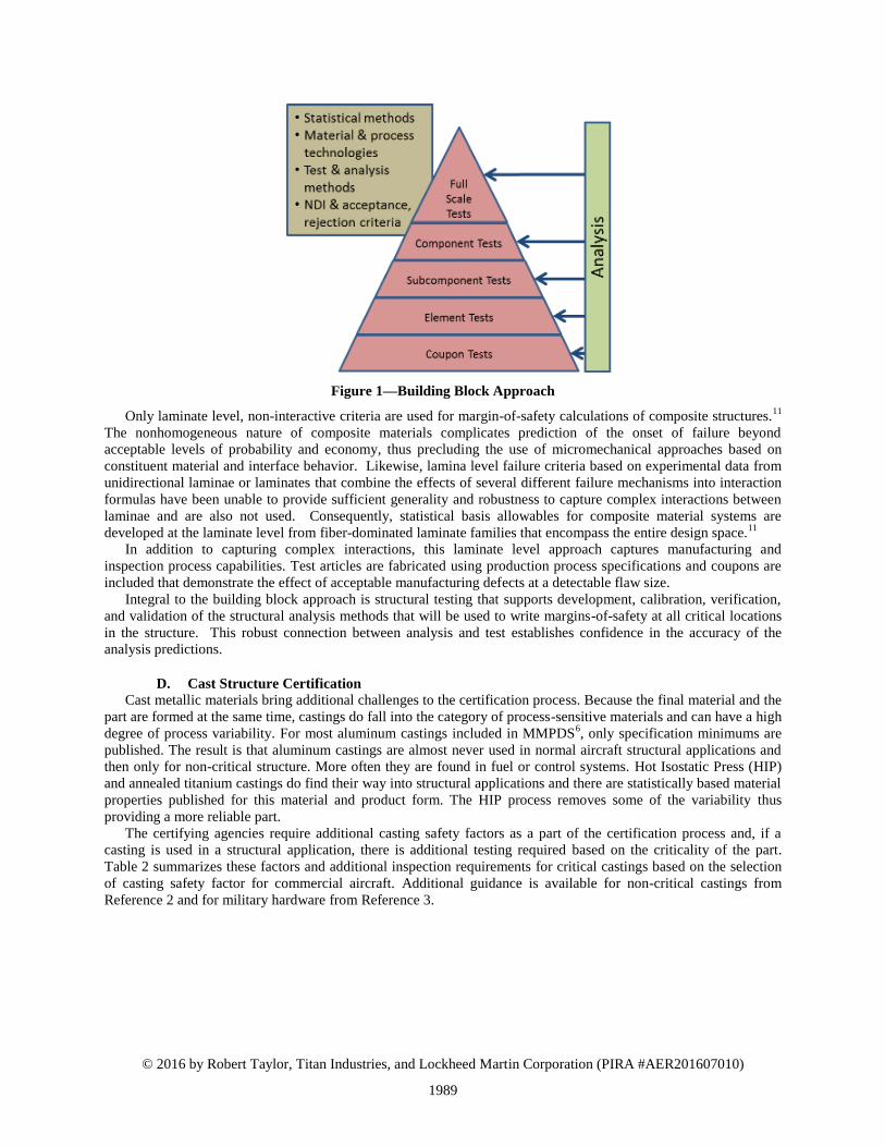
Table 2 Sample of Casting Safety Factor and Inspection Requirements per CFR 14 Part 25.621
Type
Casting
Safety
Factor
Discussion
Critical
Casting1
≥1.00
Each foundry and process variation has a material property coefficient of variation
(COV) equivalent to wrought alloy, similar composition
Prolongations and periodic cut-up required
100% Surface inspection (visual + die penetrant); Radiographic inspection of
Structurally Significant internal areas and areas of likely defect
1 casting – static test (Strength and deformation)
1.25
100% Surface inspection (visual + die penetrant); Radiographic inspection of
Structurally Significant internal areas and areas of likely defect
3 casting – static test (Strength and deformation)
≥1.50
100% Surface inspection (visual + die penetrant); Radiographic inspection of
Structurally Significant internal areas and areas of likely defect
1 casting – static test (Strength and deformation) 1Failure could preclude continued safe flight and landing of the airplane or could result in serious injury to
occupants
The selection of casting factor requires the typical flaws and defects found in cast parts are well characterized
and sufficient inspection studies have been performed to have a high confidence in the probability of detection of
these flaws. This is crucial in setting the certification requirements for castings and will also play an important role
in the certification of process sensitive AM materials.
Finally, full scale testing of cast parts for correlation to structural analysis indicates that, for the most part,
castings behave in a similar fashion to wrought materials and the familiar classical analysis methods do apply except
that typically a reduction is required for the low elongation present in castings. Additionally, the use of the plastic
bending analysis techniques are not recommended as they can be non-conservative for castings.
E. Powder Metal Structure Certification
Powder metal (PM) components present similar challenges and are treated similarly to cast components. The
presence of voids and porosity in PM components is a fundamental characteristic and void size and spacing depends
on density developed during pressing as well as post-process heat treatment. Additionally, powder material state
must be assessed in terms of powder size, shape factors, and agglomerates as these also contribute to porosity levels.
With these characteristics, PM components have testing, inspection, and analysis factors applied in a similar manner
as cast components, although the magnitude and scope of these additional processes varies depending on the severity
of the porosity developed within the PM process parameters.
F. Welded Structure Certification
Welding is another process that exhibits sensitivity in quality and achievable mechanical properties to process
parameters and operator skill. The American Welding Society has developed a multi-pronged approach to standards
to qualify operator skills and specify procedures for specific geometries and parts based on test results. At the top
level, fusion welds are qualified based on a Welding Procedure Specification (WPS), as given in AWS B02.112
,
which specifies part deposition procedures relevant to a specific application. A WPS details the welding variables
required for a specific application to ensure repeatability when the weld is performed by a qualified welder. The
WPS cites Procedure Qualification Records (PQR) for specific deposit geometries that are tested to ensure good
weld performance according to specific industry standards. For the aerospace industry, AWS D17.113
contains
requirements for fusion welding of aerospace hardware, specifies qualification requirements for welders, welding
operators, and welding procedures, and gives requirements for design, fabrication, inspection, and repair of
aerospace welded connections. Finally, welders must show knowledge and skill for a specific WPS through
individual certification. This is accomplished with a qualification test that is documented in a Welder Qualification
Test Record (WQTR) as defined in the industry standard.
This multi-pronged approach to welding qualification has relevance to a general approach to AM certification
procedures. It highlights the interdependence of geometry-, process-, and operator-specific quality of the operation.
Korbin, et al,1 from AFRL, advocate development of the PQR/WPS approach to AM qualification procedures by
1990

© 2016 by Robert Taylor, Titan Industries, and Lockheed Martin Corporation (PIRA #AER201607010)
7
generating design databases for specific AM deposit features (the PQR) that can be used to substantiate specific part
deposition procedures.
The small amount of weld allowables in MMPDS6 are given as a reduction factor on the parent material strength.
This is acceptable because welds are used for joining and typically make up a small percentage of the overall part. In
addition, another 15% joint efficiency factor is added for analysis for some welded materials. These factors are
typically conservative. Finally the certifiers require full scale testing, typically both static and fatigue and the use of
the welding procedure specification discussed above.
III. Proposed Additively Manufactured Structural Certification
Any additively manufactured structural certification approach will need to include elements from the various
certification methods described in Section II, including some form of a building block approach, testing and
inspection at multiple scales, analysis method development and validation, and standards development. Much of this
effort is well underway across a wide range of organizations.
A. Building Block Approach for AM
AM structures must follow a building block approach tailored to AM materials and processes. While evolution
of this process is in its early stages, its scope and characteristics can be deduced from the knowledge and lessons
embedded in the certification approaches discussed above. Some pertinent observations follow.
The test-model-analyze-test correlation embodied in building block approach testing provides confidence
that analysis methods accurately represent material behavior.
A qualified manufacturing process is required that produces controlled, consistent materials so that
structural design and analysis uses statistical basis material properties and allowables.
As composite structures exhibit high variation at the micro scale, inhomogeneity at the meso scale, and
interactions among constituent materials that are difficult to predict at these scales, their properties are
developed and applied at the macro scale in order to embed interactions and manufacturing effects at a
scale where they can be effectively characterized.
The process sensitivity that occurs in cast structures is effectively accounted through mitigating post-
process heat treatment that reduces variability and use in analysis of casting factors dependent on the nature
and scope of additional testing and inspection requirements. For critical applications, this can include part-
specific manufacturing process qualification.
The mechanical property degradation (i.e. low elongation, or ductility) seen in castings drives allowable
reductions and precludes use of certain analysis methods (i.e. plastic bending analysis).
The geometric sensitivity seen in welded structures is effectively accounted through geometry specific
process qualification.
Porosity levels in powder metal components depends on the powder size, shape factors, and agglomerates
of the powder material state.
Robust, comprehensive standards are the foundation for repeatable, reliable manufacturing processes,
testing, inspection, and analysis.
From these observations a framework is proposed for an AM building block approach that accounts for
variability at multiple scales and is sensitive to process parameters, material characteristics, part geometry, and
interrelationships among these variables. Development of statistically based allowables is required, but low volume
production (a key AM advantage in some applications) challenges the economics of large coupon test programs.
These material properties will be associated with specific material and process specifications, and depending on the
process variabilities, perhaps to specific manufacturing machines. Additionally key features or design details of
some parts may require element level testing for determination of notch sensitivity or detail robustness. Finally full
scale component testing will be required to determine if there are any additional effects due to scale up of the
process, details or build geometry and limitations.
B. Testing and Inspection for AM
As part of the building block approach, testing and inspection occurs at all size scales.10
The nature and scope of
such testing in the context of AM is discussed below.
1. Material and Process Specifications and Testing
Material specifications for the raw material which define constituents, raw material processing, storage, handling
and quality control are required to define the material to be used in the manufacture of aircraft parts. The process
1991

© 2016 by Robert Taylor, Titan Industries, and Lockheed Martin Corporation (PIRA #AER201607010)
8
specifications should be established once the process is reasonably well understood and required process controls
codified in the process specifications. Process specifications must fully define the manufacturing process space. As
an example they should include:
Material Specifications
Facilities Control (specific environmental requirements: temperature/humidity/cleanliness)
Material Controls (handling, storage, recycling and reuse limits)
First part Qualification Requirements
Machinery/Tool/Process/Part Requalification Requirements after machine maintenance, process
changes/improvements
Process Control Testing Requirements
Requirements for Detailed Manufacturing Plans, by Part Number
Process Description including machine type, software requirements, software and machine configuration
control
o Pre-processing requirements/equipment
o Process Parameters and Variables
o Post-Build Removal
o Post-Build Processing, e.g. thermal treatments, surface finishing, etc)
Quality Assurance and Acceptance Requirements
o In-situ inspection requirements
o Visual (part)
o NDT (part) e.g., inspect: Porosity, discontinuities, cracks, incomplete fusion and acceptance limits
o Mechanical (process control specimens) e.g., test: tensile, fracture toughness, as required, surface
roughness, as required and acceptance limits
o Metallurgical and Composition (process control specimens) – Inspect: microstructure, minimum
and maximum elemental limits
2. Coupon Testing and Statistically Based Material Properties
Coupon level testing is needed for material characterization and for basic material properties for use in the
design process. It is important that the variability be captured in the generation of the material properties, including
machine to machine variability. Table 36,14
provides the static strength subset of a proposed test matrix based on the
requirements Chapter 9 of Reference 6. In addition, to the testing for static strength properties, testing for fatigue
and fracture properties would also be required. The test coupons would be taken from an engineered test part similar
in size and shape to anticipated usage which allows for coupons to be obtained for all material directions. To capture
the process variability, multiple heats and lots and multiple machines should be used in the generation of this data.
From Reference 14, “a heat is defined as a single uniform composition. For a powder based process a heat may be
defined as a heat or lot based on the AMS7001 definition. For a wire based process a heat is based on a single wire
lot or lots of the same size produced from the same ingot in consecutive (continuous) runs.” Builds are separate
processing of parts where feedstock, process parameters, configuration or machine have changed. Prior to the start
of testing, the material and process specifications must be stable and mature.
At the current state of the art, the material properties generated from Table 3 could only be used for preliminary
design to initially size the part, followed by significant part-specific material property testing or full scale point
design testing. As a result, an argument could be made for a reduced test matrix to obtain only preliminary design
properties for use in initial sizing. However, it is anticipated that as more information becomes available and the
processes become more fully characterized that there will be a path for the use of statistically based properties for
design and analysis of additively manufactured parts based on Table 3, much in the same way as is the current
practice for wrought, cast parts or composite parts.
1992

© 2016 by Robert Taylor, Titan Industries, and Lockheed Martin Corporation (PIRA #AER201607010)
9
Table 3 Typical Test Matrix for Statistically Based Static Material Properties14
3. Inspection Methods
As discussed in item 1, inspection requirements and accept/reject limits are a part of the process specification;
however, additively manufactured parts provide both some opportunities for in-situ inspection15
that are not
available for other material product forms as well as some challenges relative to final part inspection. These methods
do not offer sufficient fidelity, as yet, to replace post-manufacture quality inspections. In-situ monitoring is most
useful in ensuring the process stays within specification parameters. Post-manufacture inspection ensures the final,
finished part meets all of the requirements and may take the form of non-destructive inspection using radiographic
or ultrasonic inspection techniques, part cut-up and metallurgical examination or the testing of traveler or
prolongation coupons.
C. Analysis Method Development for AM
While individual components can be certified by test in the absence of material allowables and validated analysis
methods, this approach does not scale to a general certification approach for AM due to the large expense of testing
every geometry, loading, environment, and failure mode for each individual component. Nevertheless, this
approach must currently be used for AM components given the uncertainties in AM materials and process.
A more general and cost- and schedule-effective approach would satisfy structural requirements primarily by
analysis supported by testing. For this approach to be a feasible AM structural certification process, validated
analysis methods are key. Given the variability in as-built AM materials and the sensitivity to microscale flaws,
analysis methods must be closely calibrated and correlated using suitable test data and a controlled manufacturing
process. From this, test data must be used to determine appropriate safety factors, based on probabilities of failure
for measured process variability levels. Furthermore, appropriate modeling idealizations at appropriate size scales
must be correlated to demonstrate analysis methods suitably predict mechanical behavior and critical failure modes
and loads. Aircraft development programs effectively use analysis methods based on classical theories, finite
element analysis, and empirical curve fitting or calibration16
to ensure close correlation and failure prediction.
Building block tests at coupon, element, component and full-scale aircraft all serve to calibrate and correlate
analysis methods.
D. Standards for AM
The development of industry accepted standards is a critical step in transitioning additive manufacturing into
practice. The creation of standards accelerates the adoption of new technology by allowing for the qualification of
new material and processes, specification of requirements, and definition of test methods and protocols.
Practitioners in industry, academia, and the regulatory agencies develop standards to communicate guidance, share
best practices, and document technical data. Standards are necessary for the additive manufacturing industry in
areas such as the following:
Powder/Feedstock Recycling Materials Technical Data Packages
Machines & Operators In-process Sensing Post Processing
Repair Safety Modeling & Simulation
Test Type Addl Info X-Orientation Y- Orientation Z-Orientation Type Heats Lots Builds Statistical Basis
Ftu 100 100 100 Direct 10 10 10 A and B
Fty 100 100 100 Direct 10 10 10 A and B
Fcy 20 20 20 Derived 3 10 10 A and B
Fsu 20 20 20 Derived 3 10 10 A and B
Bearing Yield e/D=1.5 20 (X-Y) 20 (X-Z) Derived 3 10 10 A and B
e/D=2.0 20 (X-Y) 20 (X-Z) Derived 3 10 10 A and B
Bearing Ultimate e/d=1.5 20 (X-Y) 20 (X-Z) Derived 3 10 10 A and B
e/D=2.0 20 (X-Y) 20 (X-Z) Derived 3 10 10 A and B
Coefficient of Thermal Expansion10 10 Typical
Elastic Modulus, Tension 9 9 9 3 Multiple 3 Typical
Elastic Modulus, Compression 9 9 9 3 Multiple 3 Typical
Stress-Strain Curves to Yield 6 6 3 6 6 Typical
Stress-Strain Curves full Range 6 6 3 6 6 Typical
Density 10 10
Elongation 30 30 30 3 3 3 S-Basis
Heat/Lots or Builds, as
applicable
Duplicate Measurements
1993
© 2016 by Robert Taylor, Titan Industries, and Lockheed Martin Corporation (PIRA #AER201607010)
10
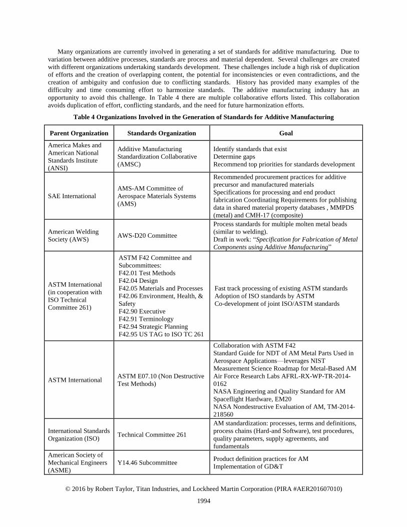
Many organizations are currently involved in generating a set of standards for additive manufacturing. Due to
variation between additive processes, standards are process and material dependent. Several challenges are created
with different organizations undertaking standards development. These challenges include a high risk of duplication
of efforts and the creation of overlapping content, the potential for inconsistencies or even contradictions, and the
creation of ambiguity and confusion due to conflicting standards. History has provided many examples of the
difficulty and time consuming effort to harmonize standards. The additive manufacturing industry has an
opportunity to avoid this challenge. In Table 4 there are multiple collaborative efforts listed. This collaboration
avoids duplication of effort, conflicting standards, and the need for future harmonization efforts.
Table 4 Organizations Involved in the Generation of Standards for Additive Manufacturing
Parent Organization Standards Organization Goal America Makes and
American National
Standards Institute
(ANSI)
Additive Manufacturing
Standardization Collaborative
(AMSC)
Identify standards that exist Determine gaps Recommend top priorities for standards development
SAE International AMS-AM Committee of
Aerospace Materials Systems
(AMS)
Recommended procurement practices for additive
precursor and manufactured materials Specifications for processing and end product
fabrication Coordinating Requirements for publishing
data in shared material property databases , MMPDS
(metal) and CMH-17 (composite)
American Welding
Society (AWS) AWS-D20 Committee Process standards for multiple molten metal beads
(similar to welding). Draft in work: “Specification for Fabrication of Metal
Components using Additive Manufacturing”
ASTM International
(in cooperation with
ISO Technical
Committee 261)
ASTM F42 Committee and
Subcommittees: F42.01 Test Methods F42.04 Design F42.05 Materials and Processes F42.06 Environment, Health, &
Safety F42.90 Executive F42.91 Terminology F42.94 Strategic Planning F42.95 US TAG to ISO TC 261
Fast track processing of existing ASTM standards Adoption of ISO standards by ASTM Co-development of joint ISO/ASTM standards
ASTM International ASTM E07.10 (Non Destructive
Test Methods)
Collaboration with ASTM F42 Standard Guide for NDT of AM Metal Parts Used in
Aerospace Applications—leverages NIST
Measurement Science Roadmap for Metal-Based AM Air Force Research Labs AFRL-RX-WP-TR-2014-
0162 NASA Engineering and Quality Standard for AM
Spaceflight Hardware, EM20 NASA Nondestructive Evaluation of AM, TM-2014-
218560
International Standards
Organization (ISO) Technical Committee 261 AM standardization: processes, terms and definitions,
process chains (Hard-and Software), test procedures,
quality parameters, supply agreements, and
fundamentals American Society of
Mechanical Engineers
(ASME) Y14.46 Subcommittee Product definition practices for AM
Implementation of GD&T
1994

© 2016 by Robert Taylor, Titan Industries, and Lockheed Martin Corporation (PIRA #AER201607010)
11
In addition to the organizations listed in Table 4, other agencies are also actively involved in the development of
standards, either directly or indirectly, including the National Institute of Standards and Technology (NIST),
NADCAP, MMPDS and NASA. NIST is primarily focused on four research thrusts, characterization of AM
materials, real-time control of AM processes, qualification of am material, processes, and parts, and AM systems
integration. The MMPDS Emerging Technology Working Group for new metallic materials is heavily involved
with SAE AMS-AM committee to generate material property data. NASA has developed the draft standard EM20,
Engineering and Qualification Standard for Additively Manufactured Parts for Spaceflight Hardware.
The regulators are reaching out to subject matter experts to guide their certification criteria. Regulators are
looking for standardization across producers through industry specifications. The FAA has identified the following
top five challenges for additive manufacturing: limited understanding of acceptable ranges of variation for key
manufacturing parameters, limited understanding of key failure mechanisms and material anomalies, lack of
industry databases/allowables, development of capable NDI methods, lack of industry specifications and
standardization. The FAA is also concerned with the lack of a robust powder supply base, the chance of an OEM-
proprietary technology path, and the low barrier to entry of new, inexperienced suppliers. It is expected that AM
will rapidly expand into aviation with increased levels of AM part criticality. This highlights the need to develop
procedures (similar approach to CMH-17 for composite materials) which would allow individual manufactures to
demonstrate that mechanical properties of parts produced at their facilities achieve ‘equivalent’ properties to
published statistically-based values.
IV. Electron Beam Melting Process Parameters
A repeatable process is critical to certification of parts fabricated by additive manufacturing. In contrast to
traditional manufacturing processes, a large number of variables are present during additive manufacturing
processes. To certify components fabricated with AM, these variables must be observed and their uncertainty
quantified. These may be measured with proper processes and quality procedures.
Due to the wide variety of additive manufacturing processes, and differences in process variables between them,
a single process (Electron Beam Melting, Arcam Q20) has been selected for the focus of this paper. Similarities in
process variables will exist, but ultimately a thorough understanding of each process is required to observe and
quantify sources of variation. The Electron Beam Melting (EBM) process is a powder bed fusion method for
additive manufacturing that utilizes an electron beam as the thermal source.
A brief overview of the Electron Beam Melting process is included below, followed by a discussion of the
primary factors that can influence part quality. The factors are grouped in four categories: Powder Quality,
Hardware Setup, Thermal Source, and Build Instructions. Factors to consider in each group are described in Table 5.
An understanding of the parameters that can vary during the process will allow for a certification plan that addresses
and quantifies each source of variation.
A. Electron Beam Melting Additive Manufacturing
The Electron Beam Melting (EBM) process is similar to other powder
bed fusion additive manufacturing processes. A thin layer of powdered
material in a powder bed is melted by a thermal source. The differences in
capabilities and limitations between laser based powder bed fusion
processes and electron beam melting (EBM) stem from the choice of
thermal source. The EBM system must occur in a vacuum since gaseous
atoms will deflect the beam. Also, since electrons are being used, magnetic
lensing controls the beam. A conceptual schematic of an EBM machine is
shown in Figure 2. Similar to that of a scanning electron microscope,
electrons are emitted by a crystal cathode that is heated by an applied
current. The electron beam is controlled by three magnetic coils, which are
housed in the lower column. The first magnetic lens corrects for
astigmatism and generates a circular electron beam with a Gaussian energy
distribution. The second magnetic lens is used to focus the beam to the
desired diameter. The third magnetic lens is used to deflect the focused
beam to the desired point on the build platform.
Magnetic control of the electron beam allows for beam deflections
without the involvement of moving mechanical parts. This results in high
scan speeds and the ability to keep multiple melt pools alive
Figure 2: EBM Conceptual
Schematic
1995

© 2016 by Robert Taylor, Titan Industries, and Lockheed Martin Corporation (PIRA #AER201607010)
12
simultaneously, which in turn allows for high build rates. Magnetic control also enables wide beam spots to scan at
high speeds to preheat each successive powder layer. This preheating reduces thermal gradients, which minimizes
residual stresses as the part is built.
Metal powder (45 –106 µm diameter) is fed to the build table from two powder hoppers. A mechanical rake
spreads the powder from the hoppers into a thin layer (90 µm) across the build table. Initially, the beam scans at a
high speed in multiple passes to preheat powder to a sintered state. After preheating, a slower beam scan is used
during the melting cycle. Upon completion of the melting cycle, the build table is lowered by one layer thickness
into the build tank and the process is repeated. The build platform moves down the z-axis as the build progresses.
When all layers have been completed, the built part is allowed to cool inside the chamber, which is then filled up
with helium to assist cooling.
During the process, the entire EBM build system, build tank and electron beam column is under vacuum. This is
required since electrons interact with the gaseous atoms, which may deflect the electrons if present. The use of
vacuum is advantageous for the process, since the vacuum will prevent reactions between reactive metals, e.g.
titanium, with atmospheric gases, such as oxygen. Additionally, the vacuum also acts an insulator to help keep the
process at an elevated temperature. The elevated temperature of the build chamber is achievable due to the high
power of the electron beam (up to 3 kW) and the ability to rapidly scan the beam in a defocused mode. The elevated
build temperature minimizes thermal gradients between the powder bed and part, which helps to prevent residual
stress build up in the finished part. The elevated temperature will also lightly sinter the powder particles surrounding
the fully melted finished part.
B. Factors Affecting Material Variability
As discussed in the previous section, the EBM process creates fully dense metal parts through layer by layer
melting of metal powders with an electron beam. Material properties of the fabricated parts depend on the thermal
history of the build. The time history of spatially deposited energy affects cooling rates, which in turn affects
microstructure. The microstructure of the part, along with any defects created during the process will determine the
material properties. Variability in material properties between builds will be created by changes in the thermal
history and process defects. Table 5 describes the factors that can create changes in thermal history. These factors
are discussed in detail below.
Table 5: Factors to Consider with EBM
Powder Quality Hardware Thermal Source Build Instructions
Chemical Composition Calibration / Alignment Cathode Age Control Software
Physical Characteristics Maintenance Cathode Current Process Themes
Inert Gas Flow Part Position / Packing Density
1. Powder Quality
Differences in the feedstock powder used between builds can affect final material properties. Chemical and
physical characteristics of the powder influence thermal history in two ways: Differences in absorption of thermal
energy and differences in ability to spread powder.
Chemical composition of the powder is especially important when the feedstock material is an alloy. Melting
and evaporation temperatures between various alloying elements differ. Thus, for the same application of energy,
differences in chemical composition will affect thermal energy absorption, which in turn affects solidification of
microstructure, or differences in defects. Chemical composition may influence the rate of defects by variation of
elements with potential to evaporate during the build. For example, when using Ti-6Al-4V for feedstock powder,
evaporation of Al is likely to occur due to its relatively low vaporization point. Evaporation of elements can create
porosity in parts, which will affect material properties.
The physical composition of feedstock powders affects the ability for the mechanical raking system to grab the
proper amount of powder for a layer and its ability to evenly spread powder across the build area. The physical
composition includes the size distribution of the powder particles (PSD), as well as the powder shape. Irregular
shapes will impact flowability. Flowability of the powder affects the size and shape of the powder heaps beneath
the powder hoppers. Variation in these heaps vary the quantity of powder spread across the plate. Too little powder
will create regions of porosity and too much powder may create layers that are too thick to be melted to the layer
below, creating delamination.
Variation in chemical and physical characteristics occurs between the individual powder blends received from
the material suppliers. This variation is inherent to the manufacturing process and unavoidable. Additional changes
to powder chemical composition and physical characteristics may occur to the same powder lot over time. Powder
1996

© 2016 by Robert Taylor, Titan Industries, and Lockheed Martin Corporation (PIRA #AER201607010)
13
that is recycled from build to build may experience changes in chemical composition due to pick up of oxygen,
evaporation of alloying elements, or due to the introduction of contamination. The physical characteristics of the
powder may also change since a majority of the powder in a build is semi-sintered during the process. This sintering
will cause shape distortion of powder particles (less spherical) and introduce satellites (smaller particles bonding to
larger particles). Both of these phenomenon cause changes in flowability and powder size distribution.
2. Hardware
The maintenance and configuration of equipment can cause variability in final parts. Hardware strongly
influences the accuracy and precision of powder layers and the time history distribution of energy. Both of these
factors create variation in the thermal history of the build. The three major subsystems influencing this most are the
rake, table, and electron magnetic lensing. The rake’s main influence over the repeatability of process stems from
the systems only goal being to spread a proper layer of powder. In pursuit of this goal the rake does not spread a
layer of powder in a consistent amount of time. It varies with powder heap size and powder flowability. This
results in a varying cooling times between layers. The table is a mechanical system that moves in the z-axis and,
under ideal conditions, is known to vary +/- 5 microns. The electron magnetic lenses are susceptible to outside
influences. Moving metal objects, high power eclectic devices cycling nearby, and other magnets can change
magnetic fields shapes. These external variables are not measured by the machine.
Calibration and alignment of the electron beam are required to apply the desired beam intensity to the desired
location. Variation in the beam intensity and location will create changes in the thermal history of the build.
Calibration of the magnetic lenses is required to compensate for the local magnetic field. This calibration process is
partially manual and as such, can introduce variability. The astigmatism, focus, and deflection lenses are calibrated,
which can lead to variation in beam spot size and spatial accuracy. Alignment of the electron beam is performed
prior to each build. This is often performed manually and may also introduce variation into beam spot size.
As discussed above, low pressure helium gas is introduced during the process. This gas is used to assist in
cooling and removal of electric charge. Variation in the flow of this gas could create variation in the process. Too
much gas will create interference with the electron beam, effectively reducing the beam energy reaching the powder
bed. Too little gas will increase the chances of part swelling or smoke events (repulsion of powder during the
process, causes porosity and deflection the electron beam by airborne particles).
3. Thermal Source
The electron beam that constitutes the thermal source in this system is generated from a crystal cathode. The
electron production has a number of sources of variability. The operator who installs and positions the cathode in
the Wehnelt cylinder (also known as the grid cup), positioning of the anode to the cathode, voltage noise present
from the power supply, age of the crystal used, and control loop used for regulation of grid voltage. All of these
items form variability in the beam current and in turn the beam power applied to the powder.
As the cathode ages, the crystal degrades. Degradation of the crystal is known to cause an increase in the beam
diameter and may influence symmetry. While the magnetic focus attempts to compensate for this degradation, the
control is open loop. Thus the accuracy of actual beam spot diameter to commanded diameter (via the focus offset)
varies as the cathode ages.
4. Build Instructions
Arcam’s additive manufacturing equipment contains a multitude of user adjustable parameters. The process
themes and control software are the largest factors in build-to-build variability. Process themes and control software
define the instructions that tell the electron beam where to be, when to be there, and how much power should be
applied. The operator of the machine is in control of all these variables. Scanning algorithms built into the control
software may vary from version to version. Operating builds with different versions of the control software will also
introduce variability. Position, orientation, and packing density of the parts within the build will influence the final
fabricated components. Changes to the build packaging will change the thermal history of the build. For repeatable
results, the position, orientation, and packaging density must be consistent from build to build. Even though the
largest source of variation may be introduce through the build instructions, these factors are the easiest to track and
control. A configuration management system that can manage the build files, process parameters, and software
versions is necessary for certification.
5. Build Defects
Due to the negative charge of the electrons that bombard the surface, the powder bed will accumulate charge if
inadequate conduction exists between the powder particles and the ground. Accumulation of charge increases the
risk of electron beam deflection, which will result in a decrease in beam accuracy and spot spreading. Additionally,
if the charge in the powder bed builds high enough, the negative repulsing forces between the powder particles will
1997
© 2016 by Robert Taylor, Titan Industries, and Lockheed Martin Corporation (PIRA #AER201607010)
14
become higher than the gravitational and friction forces holding them in place. Repulsion of powder during the
process will cause porosity and airborne particles may deflect the electron beam. Accumulation of electrical charge
is minimized by semi-sintering the powder bed to increase the conductivity between the individual powder grains,
and by additional of low pressure of inert helium gas to the vacuum chamber during the melting process.
Variation in location and frequency of build defects will influence the final material properties. Common defects
include porosity, delamination, shrinkage, and swelling. Major defects are typically caused by poor part orientation,
packaging, or supporting and are addressed with modification of build instructions during development. In a well-
developed build major defects will be corrected and the primary concern is variation in porosity. Many factors
influence porosity a list of common events follows:
Local accumulation of electric charge causes power particles to repel and creates a gap in the powder bed.
An arc trip occurs in the cathode, interrupting the electron beam and keeping powder from melting.
Evaporation of alloyed elements, removing material from the powder bed.
V. AM Fitting Design
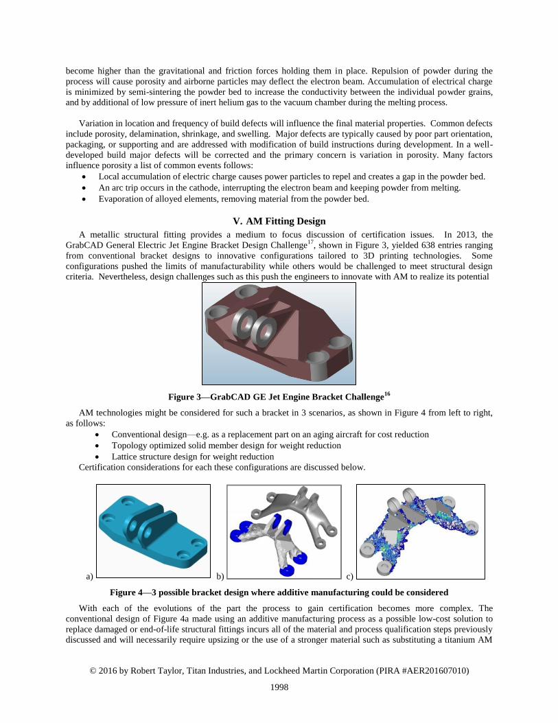
A metallic structural fitting provides a medium to focus discussion of certification issues. In 2013, the
GrabCAD General Electric Jet Engine Bracket Design Challenge17
, shown in Figure 3, yielded 638 entries ranging
from conventional bracket designs to innovative configurations tailored to 3D printing technologies. Some
configurations pushed the limits of manufacturability while others would be challenged to meet structural design
criteria. Nevertheless, design challenges such as this push the engineers to innovate with AM to realize its potential
Figure 3—GrabCAD GE Jet Engine Bracket Challenge16
AM technologies might be considered for such a bracket in 3 scenarios, as shown in Figure 4 from left to right,
as follows:
Conventional design—e.g. as a replacement part on an aging aircraft for cost reduction
Topology optimized solid member design for weight reduction
Lattice structure design for weight reduction
Certification considerations for each these configurations are discussed below.
a) b) c)
Figure 4—3 possible bracket design where additive manufacturing could be considered
With each of the evolutions of the part the process to gain certification becomes more complex. The
conventional design of Figure 4a made using an additive manufacturing process as a possible low-cost solution to
replace damaged or end-of-life structural fittings incurs all of the material and process qualification steps previously
discussed and will necessarily require upsizing or the use of a stronger material such as substituting a titanium AM
1998

© 2016 by Robert Taylor, Titan Industries, and Lockheed Martin Corporation (PIRA #AER201607010)
15
part for an aluminum wrought part. For this approach stable materials and processes, characterized through coupon
testing is necessary. It is also likely that some testing of the full scale part for critical failure modes is required. Prior
testing of components show correlation to the analysis methods is recommended, although it could be accomplished
as part of the specific part certification.
In recent years structural topology optimization18
has demonstrated its utility in configuring components for
improved structural performance.19,20,21
Commercial finite element-based topology optimization software is now
being used to configure components to leverage the capabilities22
and work within the constraints23,24
of additive
manufacturing. While topology optimization can help determine efficient structural configurations, the design
freedom opened by AM often drives these configurations to complex, intricate geometries that challenge some of the
assumptions in classical and empirical analysis methods. Furthermore, any structural criteria not explicitly
constrained in the topology optimization is completely ignored and the optimizer will leverage the omission as it
converges on a configuration. A topology-optimized solution, such as that shown in Figure 4b, will require all of the
testing of the previous example. In addition, it will likely require additional full scale testing for both static and
fatigue to ensure that the strength, life and stiffness of the optimized part is comparable to the original fitting.
A lattice-optimized part, shown in Figure 4c, would result in the most complex certification process because the
lattice structure is an unknown in terms of effect on part life. The extremely large number of stress concentrations,
unknown material characteristics (particularly at lattice intersection nodes), and unsuitability of most classical
analysis methods drive dependence on complex finite element modeling for load and stress concentration
characterization makes certification problematic. For the foreseeable future, a lattice design such as is shown in
Figure 6 likely requires a certification by test approach, thus increasing certification cost and creating part-specific
uncertainty in the certification path.
VI. Conclusion
This work has outlined a certification strategy for additively manufactured structural components based on the
lessons and knowledge developed over many years of certifying structural components from a range of
manufacturing processes. In particular, components fabricated using processes that exhibit strong sensitivity of
mechanical properties to manufacturing process parameters provide guidance in how to approach certification of
AM structures. Of particular importance in this certification strategy is an integrated approach—an AM- tailored
building block approach—that tightly connects testing, design, analysis, and inspection at all size scales. This
integrated approach relies on characterization of variability in as-built materials to develop appropriate safety
factors, application of robust standards to ensure repeatability, test-correlated and -calibrated analysis methods to
ensure physical relevance, and attention to geometry specific-variability. While AM brings substantial complexity,
variability, and substantiation challenges to structural design, the opportunities and potential to improve structural
performance, reduce costs, and influence system performance justify the great effort required to certify these
structures.
VII. References
1 Kobryn, P.A.; Ontko, N.R.; Perkins, L.P.; Tiley, J.S. (2006) Additive Manufacturing of Aerospace Alloys for
Aircraft Structures. in Cost Effective Manufacture via Net-Shape Processing (pp. 3-1 – 3-14). Meeting Proceedings
RTO-MP-AVT-139, Paper 3. Neuilly-sur-Seine, France: RTO. 2 14 CFR Part 25 Transport Category Aircraft
3 JSSG-2006, Department of Defense Joint Services Specification Guide, Aircraft Structures, 1998.
4 MIL-STD-1530C, Department of Defense Standard Practice, Aircraft Structural Integrity Program (ASIP),
2005. 5 AWB–1015, “Airworthiness Process for Deploying New or Substitute Materials, Processes, and
Product Forms,” United States Air Force Airworthiness Bulletin, Department of the Air Force, 2015. 6 Metallic Materials Properties Development and Standardization (MMPDS), Battelle Memorial Institute for the
Federal Aviation Administration, William J. Hughes Technical Center, Battelle, Columbus, OH. 7 Ball, D.L., Norwood, D.S., Termaath, S. “Joint Strike Fighter Airframe Durability and Damage Tolerance
Certification,” 47th AIAA/ASME/ASCE/AHS/ASC Structures, Structural Dynamics, and Materials Conference,
Newport, Rhode Island, 2006. 8 Ilcewicz., L.B., and Murphy, B., “Safety & Certification Initiatives for Composite Airframe Structure,” AIAA
2005-1877.
1999

© 2016 by Robert Taylor, Titan Industries, and Lockheed Martin Corporation (PIRA #AER201607010)
16
9 Composite Materials Handbook, CMH-17-3G, Vol. 3, Chapter 4.
10 Norwood, D.S., Hahn, G.L., Wippich-Dienhart, R.j., and Joyce, P.F., “A Historical Assessment of Building Block
Development Test Programs for Modern Military Aircraft,” 57th AIAA/ASCE/AHS/ASC Structures, Structural
Dynamics, and Materials Conference, San Diego, California, 2016. 11
Feraboli, P., “Composite Materials Strength Determination Within the Current Certification Methodology for
Aircraft Structures,” Journal of Aircraft, Vol. 46, No. 4., July-August 2009. 12
AWS B2.1, Specification for Welding Procedure and Performance Qualification, American Welding Society,
2014. 13
AWS D17.1, Specification for Fusion Welding for Aerospace Applications, American Welding Society, 2010. 14
Rice, R, “Guidelines for Emerging Materials and Technologies”, MMPDS Agenda Item 11-40 28th
MMPDS
Coordination Meeting Agenda, Battelle Memorial Institute, Columbus, OH 15
Everton, S.K., Hirsch, M., Stravroulakis, P., Leach, R.K. and Clare, A.T., “Review of in-situ process monitoring
and in-situ metrology for metal additive manufacturing,” Materials & Design, 95, 2016. 16
Selvarathinam, A., Rousseau, C.Q., Engelstad, S.P., and Flansburg, L, “Role of FEA, Closed-Form, and Empirical
Models in Certifying Aircraft Composite Structures,” 57th
AIAA/ASCE/AHS/ASC Structures, Structural Dynamics,
and Materials Conference at SciTech, San Diego, California, 2016. 17
https://grabcad.com/challenges/ge-jet-engine-bracket-challenge 18
Rozvany, G. I. N., “A Critical Review of Established Methods of Structural Topology Optimization,” Structural
and Multidisciplinary Optimization, January 2009, Volume 37, Issue 3, pp 217-237 19
Taylor R, Thomas J, MacKaron N, Riley S, and Lajczok M., “Detail Part Optimization on the F-35 Joint Strike
Fighter,” Proceedings of the 47th AIAA/ASME/ASCE/AHS/ASC Structures, Structural Dynamics and Materials
Conference, Newport, Rhode Island, 2006. 20
Taylor, R., “The Role of Optimization in Component Structural Design: Application to the F-35 Joint Strike
Fighter,” Proceedings of the 25th International Congress of the Aeronautical Sciences, Hamburg, Germany, 2006. 21
Taylor R., Garcia J., and Tang P., “Using Optimization for Structural Analysis Productivity Improvement on the
F-35 Lightning II,” Proceedings of the 48th AIAA/ASME/ASCE/AHS/ASC Structures, Structural Dynamics and
Materials Conference, Honolulu, HI, 2007. 22
Brackett, D., Ashcroft, I., and Hague, R.. "Topology optimization for additive manufacturing." Proceedings of the
Solid Freeform Fabrication Symposium, Austin, TX. 2011. 23
Leary, M., Merli, L., Torti, F., Mazur, M., and Brandt, M., "Optimal Topology for Additive Manufacture: A
Method for Enabling Additive Manufacture of Support-Free Optimal Structures," Materials & Design, 63 2014:678-
690. 24
Zhou, M., Lazarov, B. S., Wang, F., & Sigmund, O., “Minimum Length Scale in Topology Optimization by
Geometric Constraints,” Computer Methods in Applied Mechanics and Engineering, 293, 2015:266-282.
2000