Embed Size (px)
Citation preview


Certificates

SAKETH EXIM is an Industrial Powerhouse with a dominant presence in Manufacturing and Fabrication of Metal Products used in Pipe Support Systems, HVAC Anti Vibration System and Equipments for Industrial, Commercial, Utility and OEM Installation. Saketh Exim is Young, Agile and responsive company which is constantly expanding its capabilities to fuel its fairy tale journey that has seen it grow its standards of Research, Design, Engineering and Manufacturing that go into each and every product that comprise our Pipe Hangers Products Line. Our customer have access to the most complete Support Systems offered in the Industry, including Pipe Hangers, Metal Framing, Cable Tray, Slotted Angle. Fasteners, Rubber Support Inserts, Threaded Bars and Anchors.
Saketh's products are listed by Underwriter's Laboratory Inc. (U.S.A.) and FM Global Approved (U.S.A.) for Fire Sprinklers System Installations. All Saketh products are manufactured to meet or exceed industry standards set for their design and manufacture.
Saketh products are produced in Five advanced and technologically most advanced modern plants. These facilities are located in Commercial Capital of the India i.e. Mumbai. Regional sales and distribution centre in United States, Gulf, Asian, Countries stocking standards products.
This catalogue is designed to be helpful to engineers and contractors in the application and selection of pipe hangers, support and HVAC for construction, maintenance, fire & safety.
If a unique application require a special products not included in this catalogue, Saketh engineer personnel are ready to furnish design consultation and realistic material estimates in addition, sales representative with engineering expertise are located throughout the United States, Gulf and Asian Countries through its net work of distributors for your convenience.
Saketh reserve the right to change the specification, materials and process or the availability of products at any time without prior notice. While every effort had been made to assure the accuracy of information contained in this catalogue at the time of publication, Saketh is not responsible for in accuracies resulting from undetected errors or omissions.
INTRODUCTION
NOTICE

MATERIALS
Carbon SteelCarbon steel is used in the manufacture of Saketh pipe hangers and supports. Excellent strength characteristics and adaptability to cold forming provide a well engineered design. By cold forming the steel, mechanical properties are increased, adding to the structural integrity of the fabricated hanger.
Stainless SteelAISI Type 304 and Type 316 are non-magnetic members of the austenitic stainless steel group.Several conditions make the use of stainless steel ideal. These include reducing long term maintenance costs, high ambient temperatures, appearance, and stable structural properties such as yield strength, and high creep resistance.
CORROSIONAll metal surfaces exposed to the environment are affected by corrosion. Depending on the physical properties of the metal and its proximity to other dissimilar metals, an electrochemical reaction may occur which causes an attack on the metal itself, resulting in corrosion. Chemical corrosion is limited to highly corrosive environments, high temperatures, or a combination of both.
FINISHESZinc CoatingsProtective zinc coatings are available on a number of pipe hangers and accessories in three basic forms:Electro-galvanized, pre-galvanized, and hot-dip galvanized after fabrication. In all cases, the zinc protects the steel first as a sacrificial anode to repair bare areas on cut edges and gouges.When exposed to air and moisture, zinc forms a tough, adherent protective film consisting of a mixture of zinc oxides, hydroxides, and carbonates. The corrosion resistance of zinc is directly related to its thickness and the environment. For example a 0.2 mil (5 μm) coating will last twice as long as a 0.1 mil (2.5 μm) coating in the same environment.
Electro-Galvanized(ASTM B633 SC1 or SC3)An electro-galvanized process deposits a coating of zinc on the steel by electrolysis from a bath of zinc salts. This coating is pure zinc and adheres to the steel with a molecular bond. A maximum of 0.5 mils (12.7 μm) of zinc can be applied by this method. This coating is recommended for in-door use in relatively dry areas.
Pre-Galvanized Zinc(ASTM A653 Coating Designation G90)Pre-galvanized zinc is produced by continuously rolling the steel coils or sheets through molten zinc at the steel mills. This is also known as "mill galvanized" or "hot-dipped mill galvanized". Coils are then slit to size for fabrication of pipe hangers. Coating thicknesses of G90, is 0.90 ounces per square foot (0.27 kg/m2) of steel surface.
Cut edges and welded areas are not zinc coated; however, zinc near the uncoated metal becomes a sacrificial anode which protects the bare areas after a short period of time. Pre-galvanized steel is not generally recommended for use outdoors in industrial environments, but is suitable for extended exposure in dry or mildly corrosive atmospheres.Hot-Dip Galvanized After Fabrication (ASTM A123)After a pipe hanger or fitting has been fabricated, it is completely immersed in a bath of molten zinc. A metallurgical bond is formed, resulting in a zinc coating that completely coats all surfaces, including edges. Zinc coatings of this specification have a minimum thickness of 1.50 ounces per square foot (0.45 kg/m2) on each side or a total of 3.0 ounces per square foot (0.9 kg/m2) of steel.
Zn
ZnFe
Fe
ZnO
Protection of cut edges with zinc coatings.
TECHNICAL DATA

Hot-dip galvanized after fabrication is recommended for outdoor exposure. For best results, a zinc rich paint (available from B-Line) should be applied to field cuts. The zinc rich paint will provide immediate protection for field cuts and eliminate the short time period for galvanic action to "heal" the damaged coating.
Plastic CoatingSome products offered by Saketh are plastic or vinyl coated for prevention of galvanic reaction between materials or for noise reduction. These coated products can also be used where contact between glass pipe and hanger is not desirable. Felt lined hangers may be substituted for same purpose.
Red PrimerA corrosion resistant metal primer containing rust inhibitive pigments.
Quality AssuranceSaketh's Quality Assurance Program has been developed and implemented for compliance to various industry standards and specifications.
GeneralTorqueThe torque values in this catalog are to be used as a guide only. The relationship between the applied torque or torque wrench reading and the actual tension created in the bolt may be substantially different. Important factors affecting torque-tension relationships include friction under the bolt head or nut, hole tolerances, and torque wrench tolerances. Accuracy of many commercial torque wrenches may vary as much as plus or minus 25%.
Charts and TablesCharts and tables in this section are compiled from information published by nationally recognized organizations and are intended for use as a guide only. Saketh recommends that users of this information determine the validity of such information as applied to their own applications.
Saketh reserves the right to make specification changes without notice.SECTION 15140 - PIPE HANGERS AND SUPPORTS
Part I – GENERAL1.01 SECTION INCLUDESA. The work covered under this section consists of the furnishing of all necessary labor, supervision, materials,
equipment, and services to completely execute the pipe hanger and supports as described in this specification.
1.02 REFERENCESA. ASTM B633 - Specification for Electrodeposited Coatings of Zinc on Iron and Steel.B. ASTM A123 - Specification for Zinc (Hot-Dip Galvanized) Coatings on Iron and Steel Products.C. ASTM A653 - Specification for Steel Sheet, Zinc-Coated (Galvanized) or Zinc-Iron Alloy-Coated (Galvannealed) by
the Hot-Dip Process.D. ASTM A1011 - Specification for Steel, Sheet and Strip, Hot-Rolled, Carbon, Structural, High-Strength Low-Alloy,
and High-Strength Low-Alloy with Improved Formability.E. ANSI/MSS SP-58 - Manufacturers Standardization Society: Pipe Hangers and Supports - Materials, Design, and
Manufacture.F. ANSI/MSS SP-69 - Manufacturers Standardization Society: Pipe Hangers and Supports - Selection and
Application.G. NFPA 13 - Installation of Sprinkler Systems.
1.03 QUALITY ASSURANCEA. Hangers and supports used in fire protection piping systems shall be listed and labeled by Underwriters
Laboratories FM APPROVALS. B. Steel pipe hangers and supports shall have the manufacturer's BRAND name Tembo Sevenstar / Etalia, and
applicable size stamped in the part itself for identification.C. Hangers and supports shall be designed and manufactured in conformance with ANSI/MSS SP-58.D. Supports for sprinkler piping shall be in conformance with NFPA 13.
1.04 SUBMITTALSA. Submit product data on all hanger and support devices, including shields and attachment methods. Product data
to include, but not limited to materials, finishes, approvals, load ratings, and dimensional information.

Part II – PRODUCTS
2.01 ACCEPTABLE MANUFACTURERSA. Manufacturer: Subject to compliance with these specifications, pipe hanger and support systems shall be as manufactured
by Saketh Exim Pvt. Ltd.
2.02 PIPE HANGERS AND SUPPORTSA. HANGERS1. Uninsulated pipes 2 inches and smaller:
a. Sprinkler Hanger.b. Pipe Hanger.c. Clevis Hanger.
B. VERTICAL SUPPORTS1. Steel Riser Clamp sized to fit outside diameter of pipe.
C. COPPER TUBING SUPPORTS 1. Hangers shall be sized to fit copper tubing outside diameters.
a. Sprinkler Hanger.b. Pipe Hanger.c. Clevis Hanger.
D. SUPPLEMENTARY STRUCTURAL SUPPORTS1. Design and fabricate supports using structural quality steel bolted framing materials as manufactured by Saketh. Channels
shall be roll formed, 12 gauge ASTM A1011 SS Grade 33 steel, 15/8” x 15/8” or greater as required by loading conditions. Submit designs for pipe tunnels, pipe galleries, etc., to engineer for approval. Use clamps and fittings designed for use with the strut system.
2.04 UPPER ATTACHMENTSA. BEAM CLAMPS
1. Beam clamps shall be used where piping is to be suspended from building steel. Clamp type shall be selected on the basis of load to be supported, and load configuration.
2. C-Clamps shall have locknuts and cup point set screws.3. Center loaded beam clamps shall be used where specified.
B. CONCRETE INSERTS1. Cast in place spot concrete inserts shall be used where applicable; either steel or malleable iron body. Spot inserts shall
allow for lateral adjustment and have means for attachment to forms. Select insert nuts to suit threaded hanger rod sizes.2. Continuous concrete inserts shall be used where applicable. Channels shall be 12 gauge, ASTM A 1011 SS Grade 33
structural quality carbon steel, complete with Styrofoam inserts and end caps with nail holes for attachment to forms. The continuous concrete insert shall have a load rating of 2,000 lbs/ft. suitable for strut and rod sizes.
2.05 VIBRATION ISOLATION AND SUPPORTSA. For refrigeration, air conditioning, hydraulic, pneumatic, and other vibrating system applications, uses a clamp that has a
vibration dampening insert and a nylon inserted locknut.B. For larger tubing or piping subjected to vibration, use neoprene or spring hangers as required.C. For base mounted equipment use vibration pads, molded neoprene mounts, or spring mounts as required.D. Vibration isolation products are manufactured by Saketh Exim Pvt. Ltd.
2.06 ACCESSORIESA. Hanger rods shall be threaded both ends. Or continuous threaded rods of circular cross section. Use adjusting locknuts at
upper attachments and hangers. No wire, chain, or perforated straps are allowed.
B. Shields shall be 180° galvanized sheet metal, 12 inch minimum length, 18 gauge minimum thickness, designed to match outside diameter of the insulated pipe.
C. Pipe protection saddles shall be formed from carbon steel, 1/8 inch minimum thickness, sized for insulation thickness. Saddles for pipe sizes greater than 12 inch shall have a center support rib.
2.07 FINISHESINDOOR FINISHESA. Hangers and clamps for support of bare copper piping shall be coated with copper colored epoxy paint. Additionally a plastic
coating or a felt lining in hanger can be used.B. Hangers for other than bare copper pipe shall be zinc plated in accordance with ASTM B633-SC3.C. Strut channels shall be pre-galvanized in accordance with ASTM A653 G90 or have an electro-deposited green epoxy finish.
OUTDOOR AND CORROSIVE AREA FINISHESD. Hangers and strut located outdoors shall be hot dip galvanized after fabrication in accordance with ASTM A123. All hanger
hardware shall be hot-dip galvanized or stainless steel. Zinc plated hardware is not acceptable for outdoor or corrosive use.E. Hangers and strut located in corrosive areas shall be Type 304 (316) stainless steel with stainless steel hardware.

Clevis HangerPage 1
Sprinkler HangerPage 2
Pipe Hanger without LiningPage 4
Pipe HangerPage 6-7
Pipe Hanger -Heavy DutyPage 8
Two Bolt Pipe ClampsPage 9
Riser ClampPage 11
Riser Clamp With LiningPage 12
Riser Clamp-Four BoltsPage 13
U StrapPage 14-15
U Strap with LiningPage 16-17
Two Bolt Pipe Clamp with LiningPage 10
Pipe Hanger with EPDM LiningPage 3
INDEX
Pipe Hanger with EPDM LiningPage 5

Two Bolt Pipe Clamp with LiningPage
Light SaddlePage 21
Heavy SaddlePage 22
Offset HangerPage 23
Pipe Roller StandPage 25
Pipe RollerPage 28
Pipe Insulation SaddlePage 29
Spring HangerPage 34
Rubber Support InsertsPage 30-33
Half SaddlePage 20
U Bolt with LiningPage 19
Adjustable Roller HangerPage 27
Pipe Roller ChairPage 26
Two Piece Channel Clip (strut Pipe|tube Clamp /Strut Mounting Pipe GuidePage 24
U BoltPage 18

Rubber PadsPage 43-44
Turret MountPage 42
Cup Spring MountPage 45
Anti Vibration PadsPage 40-41
Floating Flange Expansion JointPage 39
Single Arch Expansion JointPage 37-38
Closed Spring MountPage 35-36
Cup Spring Mount “A”Page 46
Enclosed Spring IsolatorPage 47
Open Spring MountingsPage 48-49
Closed Spring IsolatorPage 50
Restraint ModelPage 53
Inertia BasePage 51-52
Double Arch Expansion JointsPage 54-56

Accessory SeriesPage 90
Flexible Metallic Pump ConnectorPage 61
Metallic Expansion JointsPage 57-60
Beam Clamp
Page 62
Gate Valve
Page 96-102
Threaded Rods Page 63-64
Floor DrainsPage 91-95
Installation Instruction
Testing of Product
Page 112-119
Stud Bolts& Anchor BoltsPage 65-67
Bolts, Nuts& Washers Page 68-88
Butterfly Valve
Page 106-109
Y Strainer
Page 110-111
Check Valve
Page 103-105
Drop In Anchor
& Draw In Anchor
Page 89

Pipe
Han
gersPipe
Hangers


APPLICATION: A CLEVIS HANGER provides for sizeable loads to be supported and for an elevation adjustment depending upon the pipe diameter. The lower nut adjusts the piping to the proper elevation and the upper nut, when locked into position, prevents loosening due to vibration.
CONSTRUCTION: A CLEVIS HANGER consists of a yoke and a support strap made from shaped carbon steel strip and a joining bolt. 15° swing in either direction allows pipe to easily feed through. Pipe will not pinch when installing. Engineered design aligns bolt holes for quicker overhead installation.
MATERIAL: Carbon Steel. Also other materials can also be provided on request
APPROVALS: Underwriter's Laboratory (UL) Factory Mutual's (FM) Manufacturers Standardization Society ANSI/MSS SP-69 & SP-58 (Type 1)Federal Specification WW-H-171E & A-A-1192A (Type 1)
MAXIMUM TEMPERATURE: 343°C (650°F)
FINISH AVAILABLE: Plain, Hot Dip Galvanized, Electro-Galvanized.
CLEVIS HANGER
1
Product Code
Nominal Pipe Size Pipe OD (mm)
D
Material Dimension (mm) Hanger Rod Size (mm)
R
Cross Bolt Dia.
(CRD )
MAX LOAD (KG) In. mm
Height H
Top Hole Dia. S
SE-CH- 0.50 ½” DN15 21.3 68 11 M10 M8 350
SE-CH- 0.75 ¾” DN20 26.7 72 11 M10 M8 350
SE-CH- 01 1” DN25 33.4 76 11 M10 M8 350
SE-CH- 1.25 1 ¼” DN32 42.1 87 11 M10 M8 350
SE-CH- 1.50 1 ½” DN40 48.2 97 11 M10 M8 350
SE-CH- 02 2” DN50 60.3 114 11 M10 M8 350
SE-CH- 2.50 2 ½” DN65 73.0 142 13 M12 M10 780
SE-CH- 03 3” DN80 88.9 165 13 M12 M10 780
SE-CH- 04 4” DN100 114.3 202 13 M12 M10 780
SE-CH- 05 5” DN125 141.3 236 13 M12 M12 1250
SE-CH- 06 6” DN150 168.3 278 13 M12 M12 1250
SE-CH- 08 8” DN200 219.1 338 13 M12 M12 2100
SE-CH- 10 10” DN250 273.1 419 17 M16 M16 2100
SE-CH- 12 12” DN300 323.8 490 21 M20 M20 2100
SE-CH- 14 14” DN350 355.6 556 21 M20 M20 3800
SE-CH- 16 16” DN400 406.4 610 25 M24 M20 3800
SE-CH- 18 18” DN450 457.2 675 25 M24 M24 4000
SE-CH- 20 20” DN500 508.0 715 32 M30 M24 4000
SE-CH- 14 24” DN600 609.6 850 32 M30 M24 9400
SE-CH- 30 30” DN750 762.0 995 32 M30 M24 9400
Pipe
Han
gers

APPLICATION: A SPRINKLER HANGER recommended to provide vertical support to non insulated piping systems. By adjusting the position of the sprinkler nut on the hanger rod at the top of the hanger, pipe elevation can be altered.
CONSTRUCTION: A SPRINKLER HANGER consists of a piece of carbon steel shaped to support pipe. Gives Double thickness at the support. Most suitable for fire extinguishing pipes installation. MATERIAL: Carbon Steel. Also other materials can also be provided on request
MAXIMUM TEMPERATURE: 343°C (650°F)
APPROVALS:
Underwriter's Laboratories (UL) Factory Mutual Approved (FM) Manufacturers Standardization Society ANSI/MSS SP-69 & SP-58 (Type10)Federal Specification WW-H-171E & A-A-1192A (Type 10)
FINISH AVAILABLE: Plain, Hot Dip Galvanized, Electro-Galvanized.
SPRINKLER HANGER
2
Product Code Nominal Pipe Size Pipe OD
(mm) D
Height H
Hanger Rod Size (mm)
R
MAX LOAD (KG) In. mm
SE-SH – 0.75 ¾” DN20 26.7 61 M10 220
SE-SH – 01 1" DN25 33.4 70 M10 220
SE-SH – 1.25 1 ¼” DN32 42.1 78 M10 220
SE-SH – 1.5 1 ½” DN40 48.2 84 M10 220
SE-SH – 02 2” DN50 60.3 102 M10 220
SE-SH – 2.5 2 ½” DN65 73.0 118 M10 300
SE-SH – 03 3” DN80 88.9 144 M10 300
SE-SH – 04 4” DN100 114.3 176 M10 300
SE-SH – 06 6” DN150 168.3 262 M12 550
SE-SH – 08 8” DN200 219.1 305 M12 1300
SE-SH – 10 10’’ DN250 273.0 315 M12 1300
SE-SH – 12 12’’ DN300 323.8 378 M12 1300
WITH SPRINKLER NUT
Product Code Nominal Pipe Size Pipe OD
(mm) D
Height H
Hole Size (mm)
R
MAX LOAD (KG) In. mm
SE-SHWN – 0.75 ¾” DN20 26.7 61 M10 220
SE-SHWN – 01 1" DN25 33.4 70 M10 220
SE-SHWN – 1.25 1 ¼” DN32 42.1 78 M10 220
SE-SHWN – 1.5 1 ½” DN40 48.2 84 M10 220
SE-SHWN – 02 2” DN50 60.3 102 M10 220
SE-SHWN – 2.5 2 ½” DN65 73.0 118 M10 300
SE-SHWN – 03 3” DN80 88.9 144 M10 300
SE-SHWN – 04 4” DN100 114.3 176 M10 300
SE-SHWN – 06 6” DN150 168.3 262 M12 550
SE-SHWN – 08 8” DN200 219.1 305 M12 1300
SE-SHWN – 10 10’’ DN250 273.0 315 M12 1300
SE-SHWN – 12 12’’ DN300 323.8 378 M12 1300
WITHOUTSPRINKLER NUT
SPRINKLER HANGER WITHOUT NUT
PIPE HANGER WITH EPDM LINING
3
Product Code
Nominal Pipe Size Pipe OD (mm)
Range (mm)
Hanger Rod Size (mm)
( A )
Side Screw size
MAX LOAD (KG) In. mm
SE-ULNCL 0.5 ½” DN15 21.3 20-25 M10 M6 460
SE-ULNCL 0.75 ¾” DN20 26.7 26-30 M10 M6 460
SE-ULNCL 01 1" DN25 33.4 32-36 M10 M6 460
SE-ULNCL 1.25 1 ¼” DN32 42.1 38-43 M10 M6 460
SE-ULNCL 1.50 1 ½” DN40 48.2 47-51 M10 M6 460
SE-ULNCL 02 2" DN50 60.3 60-64 M10 M6 460
SE-ULNCL 2.50 2 ½” DN65 73.0 74-80 M10 M6 570
SE-ULNCL 03 3" DN80 88.9 87-92 M10 M6 570
SE-ULNCL 3.50 3 ½” DN90 101.6 99-105 M10 M6 570
SE-ULNCL 04 4" DN100 114.3 113-118 M10 M6 570
SE-ULNCL 05 5” DN125 141.3 138-142 M12 M6 570
SE-ULNCL 06 6" DN150 168.3 168-172 M12 M8 570
SE-ULNCL 08 8" DN200 219.1 215-220 M12 M8 930
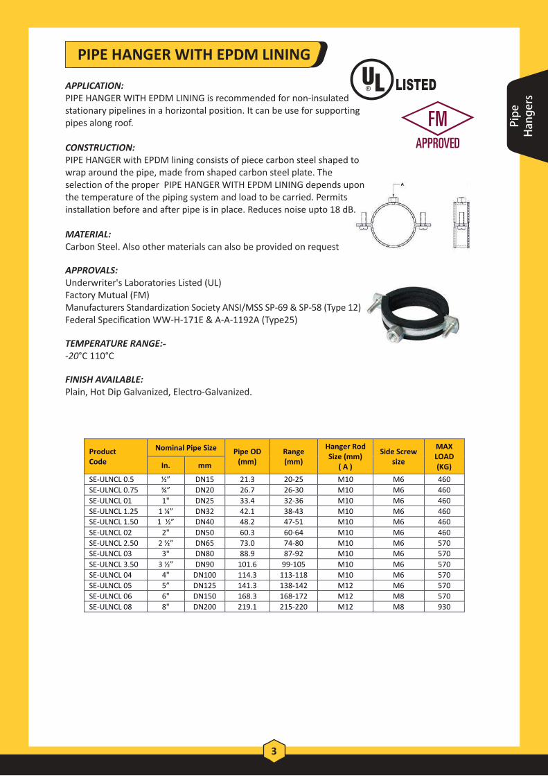
APPLICATION: PIPE HANGER WITH EPDM LINING is recommended for non-insulated stationary pipelines in a horizontal position. It can be use for supporting pipes along roof.
CONSTRUCTION: PIPE HANGER with EPDM lining consists of piece carbon steel shaped to wrap around the pipe, made from shaped carbon steel plate. The selection of the proper PIPE HANGER WITH EPDM LINING depends upon the temperature of the piping system and load to be carried. Permits installation before and after pipe is in place. Reduces noise upto 18 dB.
MATERIAL: Carbon Steel. Also other materials can also be provided on request
APPROVALS:Underwriter's Laboratories Listed (UL) Factory Mutual (FM) Manufacturers Standardization Society ANSI/MSS SP-69 & SP-58 (Type 12)Federal Specification WW-H-171E & A-A-1192A (Type25)
TEMPERATURE RANGE:- -20°C 110°C
FINISH AVAILABLE: Plain, Hot Dip Galvanized, Electro-Galvanized.
Pipe
Han
gers

PIPE HANGER WITHOUT LINING
4
Product Code
Nominal Pipe Size Pipe OD
(mm) Range (mm)
Hanger Rod Size (mm)
( A )
Side Screw
size
MAX LOAD (KG) In. mm
SE-ULNC 0.5 ½” DN15 21.3 20-25 M10 M6 460
SE-ULNC 0.75 ¾” DN20 26.7 26-30 M10 M6 460
SE-ULNC 01 1" DN25 33.4 32-36 M10 M6 460
SE-ULNC 1.25 1 ¼” DN32 42.1 38-43 M10 M6 460
SE-ULNC 1.50 1 ½” DN40 48.2 47-51 M10 M6 460
SE-ULNC 02 2" DN50 60.3 60-64 M10 M6 460
SE-ULNC 2.50 2 ½” DN65 73.0 74-80 M10 M6 570
SE-ULNC 03 3" DN80 88.9 87-92 M10 M6 570
SE-ULNC 3.50 3 ½” DN90 101.6 99-105 M10 M6 570
SE-ULNC 04 4" DN100 114.3 113-118 M10 M6 570
SE-ULNC 05 5” DN125 141.3 138-142 M12 M6 570
SE-ULNC 06 6" DN150 168.3 168-172 M12 M8 570
SE-ULNC 08 8" DN200 219.1 215-220 M12 M8 930
APPLICATION: PIPE HANGER is recommended for non-insulated stationary pipe lines in either a horizontal or vertical position. It can be use for supporting pipes along roof as well as along wall
CONSTRUCTION: PIPE HANGER consists of piece of carbon steel shaped to wrap around the pipe, made from shaped carbon steel plate. The selection of the PIPE CLAMP depends upon the temperature of piping system and load to be carried. Pipe hanger permits installation before and after pipe is placed.
MATERIAL: Steel. Also other materials can also be provided on request.
APPROVALS: Underwriter's Laboratories Listed (UL)Factory Mutual (FM)Manufacturers Standardization Society ANSI/MSS SP-69 & SP – 58 (Type 58) Federal Specification WW-H-171E & A-A-1192A (Type 25)
MAXIMUM TEMPERATURE: 343°c (650°F)
FINISH AVAILABLE: Plain, Hot dipped Galvanised, Electro-Galvanized.

PIPE HANGER WITH EPDM LINING
APPLICATION: PIPE HANGER WITH EPDM LINING is recommended for non-insulated stationary pipelines in a horizontal position. It can be use for supporting pipes along roof.
CONSTRUCTION: PIPE HANGER with EPDM lining consists of piece carbon steel shaped to wrap around the pipe, made from shaped carbon steel plate. The selection of the proper PIPE HANGER WITH EPDM LINING depends upon the temperature of the piping system and load to be carried. Permits installation before and after pipe is in place. Reduces noise upto 18 dB.
MATERIAL: Carbon Steel. Also other materials can also be provided on request
APPROVALS:
• Manufacturers Standardization Society ANSI/MSS SP-69 & SP-58 (Type 12)
• Federal Specification WW-H-171E & A-A-1192A (Type25)
TEMPERATURE RANGE: -20°C 110°C
FINISH AVAILABLE: Plain, Hot Dip Galvanized, Electro-Galvanized.
85
Product Code
Nominal Pipe Size Pipe OD (mm)
Range (mm)
Nut Size ( A )
Side Screw size
MAX LOAD (KG) In. mm
SE-NCL 0.375 ? ” DN10 17.1 15-19 M8 X M10 M6 450
SE-NCL 0.5 ½” DN15 21.3 20-25 M8 X M10 M6 450
SE-NCL 0.75 ¾” DN20 26.7 26-30 M8 X M10 M6 450
SE-NCL 01 1" DN25 33.4 32-36 M8 X M10 M6 450
SE-NCL 1.25 1 ¼” DN32 42.1 38-43 M8 X M10 M6 450
SE-NCL 1.50 1 ½” DN40 48.2 47-51 M8 X M10 M6 450
SE-NCL 54 - 54 53-58 M8 X M10 M6 450
SE-NCL 02 2" DN50 60.3 60-64 M8 X M10 M6 450
SE-NCL 63 - 63 63-66 M8 X M10 M6 450
SE-NCL 70 - 70 68-72 M8 X M10 M6 450
SE-NCL 2.15 2 ½” DN65 73.0 74-80 M8 X M10 M6 600
SE-NCL 83 - 83 81-86 M8 X M10 M6 600
SE-NCL 03 3" DN80 88.9 87-92 M8 X M10 M6 600
SE-NCL 3.5 3 ½” DN90 101.6 99-105 M8 X M10 M6 600
SE-NCL 110 - 110 107-112 M8 X M10 M6 600
SE-NCL 04 4" DN100 114.3 113-118 M8 X M10 M6 600
SE-NCL 125 - 125 125-130 M8 X M10 M6 600
SE-NCL 133 - 133 131-137 M8 X M10 M6 600
SE-NCL 05 5” DN125 141.3 138-142 M8 X M10 M6 600
SE-NCL 150 - 150 148-153 M8 X M10 M6 600
SE-NCL 160 - 160 159-166 M8 X M10 M6 600
SE-NCL 06 6" DN150 168.3 168-172 M8 X M10 M8 600
SE-NCL 210 - 210 200-212 M8 X M10 M8 950
SE-NCL 08 8” DN200 219.1 215-220 M8 X M10 M8 950
SE-NCL 10 10” DN250 273.0 269-274 M8 X M10 M8 950
SE-NCL 12 12” DN300 323.8 313-318 M8 X M10 M8 1200
3/8”
Pipe
Han
gers

PIPE HANGER
APPLICATION: PIPE HANGER is recommended for non-insulated stationary pipe lines in either a horizontal or vertical position. It can be use for supporting pipes along roof as well as along wall.
CONSTRUCTION: PIPE HANGER consists of piece carbon steel shaped to wrap around the pipe, made from shaped carbon steel plate. The selection of the proper 3-Bolt PIPE CLAMP depends upon the temperature of the piping system and load to be carried. Permits installation before and after pipe is in place. MATERIAL: Steel. Also other materials can also be provided on request
APPROVALS:Manufacturers Standardization Society ANSI/MSS SP-69 & SP-58 (Type 12)Federal Specification WW-H-171E & A-A-1192A (Type25) MAXIMUM TEMPERATURE: 343°C (650°F)
FINISH AVAILABLE: Plain, Hot Dip Galvanized, Electro-Galvanized.
6
Product Code
Nominal Pipe Size Size (mm)
Range (mm)
Nut Size (mm) ( A )
Side Screw
size
MAX LOAD (KG) In. mm
SE-NC 0.375 3/8” DN10 17.1 15-19 M8 X M10 M6 450
SE-NC 0.50 ½” DN15 21.3 20-25 M8 X M10 M6 450
SE-NC 0.75 ¾” DN20 26.7 26-30 M8 X M10 M6 450
SE-NC 01 1" DN25 33.4 32-36 M8 X M10 M6 450
SE-NC 1.25 1 ¼” DN32 42.1 38-43 M8 X M10 M6 450
SE-NC 1.50 1 ½” DN40 48.2 47-51 M8 X M10 M6 450
SE-NC 54 - 54 53-58 M8 X M10 M6 450
SE-NC 02 2" DN50 60.3 60-64 M8 X M10 M6 450
SE-NC 63 - 63 63-66 M8 X M10 M6 450
SE-NC 70 - 70 68-72 M8 X M10 M6 450
SE-NC 2.50 2 ½” DN65 73.0 74-80 M8 X M10 M6 600
SE-NC 83 - 83 81-86 M8 X M10 M6 600
SE-NC 03 3" DN80 88.9 87-92 M8 X M10 M6 600
SE-NC 3.50 3 ½” DN90 101.6 99-105 M8 X M10 M6 600
SE-NC 110 - 110 107-112 M8 X M10 M6 600
SE-NC 04 4" DN100 114.3 113-118 M8 X M10 M6 600
SE-NC 125 - 125 125-130 M8 X M10 M6 600
SE-NC 133 - 133 131-137 M8 X M10 M6 600
SE-NC 05 5” DN125 141.3 138-142 M8 X M10 M6 600
SE-NC 150 - 150 148-153 M8 X M10 M6 600
SE-NC 160 - 160 159-166 M8 X M10 M6 600
SE-NC 06 6" DN150 168.3 168-172 M8 X M10 M8 600
SE-NC 210 - 210 200-212 M8 X M10 M8 950
SE-NC 08 8” DN200 219 215-220 M8 X M10 M8 950
SE-NC 10 10” DN250 273.0 269-274 M8 X M10 M8 950
SE-NC 12 12” DN300 323.8 313-318 M8 X M10 M8 1200
3/8”

7
ABS = Acrylonitrile-Butadiene-StyreneuPVC = unplasticized polyvinyl chloridepe = Polyethylene
SELECTION TABLE FOR DIFFERENT TYPES OF PIPES
NPS (in)
Pipe outside Dia(mm)
uPVC/ PE (mm)
ABS (mm)
Copper (mm)
- 16 - - 15,18
1/2" 22 20 DN15(21.4) 22
3/4" 28 25 DN20(26.8) 24, 28
1" 35 32, 38 DN25(33.6) 35
1 1/4" 42 40, 43 DN32(42.3) 42
1 1/2" 48 45 DN40(48.3) -
- - 54 - 54
2" 60 60 DN50(60.4) 64
- - - - -
- - 70 67, 70
2 1/2" 75 75 DN65(75.4) 76
- - 83 - 80
3" 90 90 - -
- - 102 DN80(88.9) 102, 105
- - 110 - 108
4" 115 115 DN100(114.3) -
- - 125 - 125
- - 135 - -
5" 140 140 DN125(121.4) -
- - 152 - -
- - 160 - 159
6" 168 - DN150(168.3) 167
- - 200 - 206
8" 219 220, 225 DN200(225.0) -
- - 250 DN225(250.4) -
- - - DN300(315.5) -
Pipe
Han
gers

PIPE HANGER – HEAVY DUTY
8
Product Code
Nominal Pipe Size Pipe OD
(mm) Range (mm)
Nut Size (mm) ( A )
Side Screw size
MAX LOAD (KG) In. mm
SE-HNCL 0.375 ? ” DN10 17.1 15-19 M8 X M10 M6 500
SE-HNCL 0.5 ½” DN15 21.3 20-25 M8 X M10 M6 500
SE-HNCL 0.75 ¾” DN20 26.7 26-30 M8 X M10 M6 500
SE-HNCL 01 1" DN25 33.4 32-36 M8 X M10 M6 500
SE-HNCL 1.25 1 ¼” DN32 42.1 38-43 M8 X M10 M6 500
SE-HNCL 1.50 1 1/2” DN40 48.2 47-51 M8 X M10 M6 500
SE-HNCL 54 - 54 53-58 M8 X M10 M6 500
SE-HNCL 02 2" DN50 60.3 60-64 M8 X M10 M6 500
SE-HNCL 63 - 63 63-66 M8 X M10 M6 550
SE-HNCL 70 - 70 68-72 M8 X M10 M6 550
SE-HNCL 2.15 2 ½” DN65 73.0 74-80 M8 X M10 M6 700
SE-HNCL 83 - 83 81-86 M8 X M10 M6 700
SE-HNCL 03 3" DN80 88.9 87-92 M8 X M10 M6 700
SE-HNCL 3.5 3 ½” DN90 101.6 99-105 M8 X M10 M6 700
SE-HNCL 110 - 110 107-112 M8 X M10 M6 700
SE-HNCL 04 4" DN100 114.3 113-118 M8 X M10 M6 700
SE-HNCL 125 - 125 125-130 M8 X M10 M6 700
SE-HNCL 133 - 133 131-137 M8 X M10 M6 700
SE-HNCL 05 5” DN125 141.3 138-142 M8 X M10 M6 700
3/8”
APPLICATION: HEAVY DUTY PIPE HANGER is recommended for non-insulated stationary heavy pipe lines in either a horizontal or vertical position. It can be use for supporting pipes along roof as well as along wall. Used where loads to be carried are larger in magnitude.
CONSTRUCTION: HEAVY DUTY PIPE HANGER consists of piece carbon steel shaped to wrap around the pipe, made from shaped carbon steel plate. Quick – Locking permits simple and fast installation. Large opening angles for easy insertion of the pipes. Clamping range without gaps. Reduces noise upto 18 dB.
MATERIAL: Steel. Also other materials can also be provided on request
APPROVAL: Manufacturers Standardization Society ANSI/MSS SP-69 & SP-58 (Type 12)Federal Specification WW-H-171E & A-A-1192A (Type25) MAXIMUM TEMPERATURE: 110°CMINIMUM TEMPERATURE: -20°CFINISH AVAILABLE: Plain, Hot Dip Galvanized, Electro-Galvanized.

APPLICATION: Recommended for suspension of cold pipe lines or hot lines where no insulation is required.
CONSTRUCTION: PIPE CLAMPS consists of two carbon steel flat bars bent to shape and held together by two bolts.
MATERIAL: Steel. Also other materials can also be provided on request
APPROVALS: Manufacturers Standardization Society ANSI/MSS SP-69 & SP-58 (Type 4)Federal Specification WW-H-171E & A-A-1192A (Type 4)
MAXIMUM TEMPERATURE: 343°C (650°F)
FINISH AVAILABLE: Plain, Hot Dip Galvanized, Electro-Galvanized.
TWO BOLT PIPE CLAMPS
9
Product
Code
Nominal Pipe Size Pipe OD
(mm)
DIMESNSIONS(mm) MAX LOAD
(kg) In. mm
LENGTH
A
BOLT
SIZE B GAP G
SE-TBC 0.5 ½’’ DN15 21.3 200 M10 12 170
SE-TBC 0.75 ¾’’ DN20 26.7 210 M10 12 170
SE-TBC 1 1’’ DN25 33.4 230 M10 12 170
SE-TBC 1.25 1 ¼’’ DN32 42.1 260 M10 12 170
SE-TBC 1.5 1 ½’’ DN40 48.2 260 M10 12 170
SE-TBC 2 2’’ DN50 60.3 260 M10 16 170
SE- TBC 2.5 2 ½’’ DN65 73.0 290 M12 16 400
SE- TBC 3 3’’ DN80 88.9 290 M12 16 400
SE- TBC 3.5 3 ½’’ DN90 101.6 330 M12 16 400
SE- TBC 4 4’’ DN100 114.3 330 M12 19 400
SE- TBC 5 5’’ DN125 141.3 350 M16 19 600
SE- TBC 6 6’’ DN150 168.3 380 M16 22 600
SE- TBC 8 8’’ DN200 219.1 470 M16 25 1100
SE- TBC 10 10’’ DN250 273.0 520 M16 25 1200
SE- TBC 12 12’’ DN300 323.8 580 M20 25 1500
SE- TBC 14 14’’ DN350 355.6 610 M20 28 1500
SE- TBC 16 16’’ DN400 406.4 660 M20 28 2200
SE- TBC 18 18’’ DN450 457.2 710 M20 32 2200
SE- TBC 20 20’’ DN500 508.0 760 M20 35 2200
SE- TBC 24 24’’ DN600 609.6 880 M20 42 2200
Pipe
Han
gers
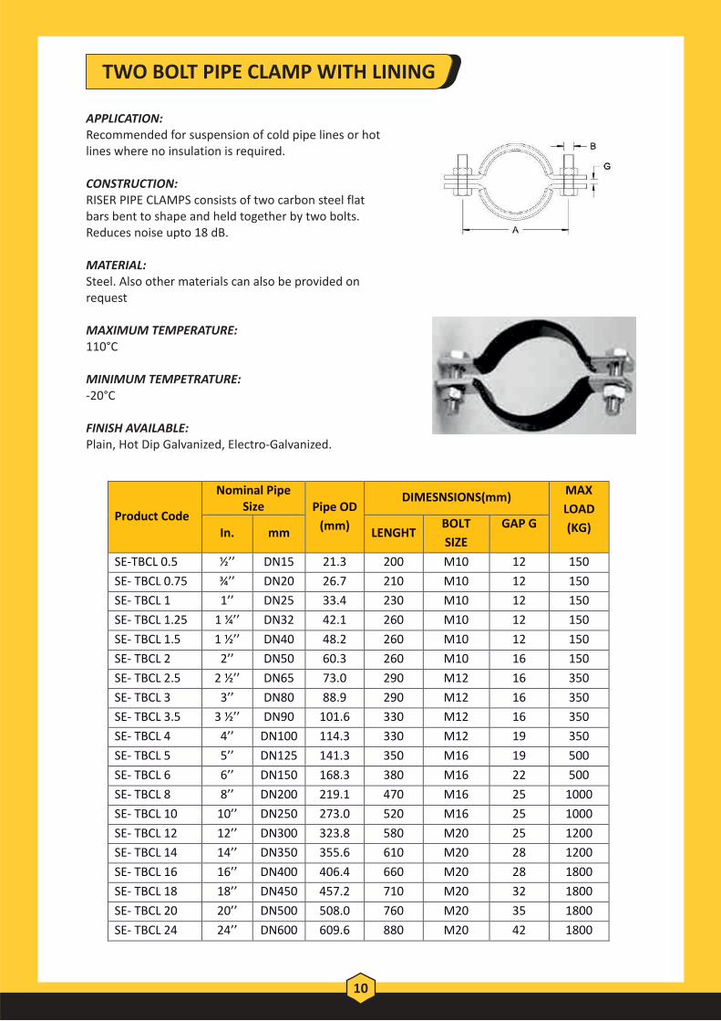
APPLICATION: Recommended for suspension of cold pipe lines or hot lines where no insulation is required.
CONSTRUCTION: RISER PIPE CLAMPS consists of two carbon steel flat bars bent to shape and held together by two bolts. Reduces noise upto 18 dB.
MATERIAL: Steel. Also other materials can also be provided on request
MAXIMUM TEMPERATURE: 110°C
MINIMUM TEMPETRATURE: -20°C
FINISH AVAILABLE: Plain, Hot Dip Galvanized, Electro-Galvanized.
TWO BOLT PIPE CLAMP WITH LINING
10
Product Code
Nominal Pipe Size Pipe OD
(mm)
DIMESNSIONS(mm) MAX
LOAD
(KG) In. mm LENGHT BOLT
SIZE
GAP G
SE-TBCL 0.5 ½’’ DN15 21.3 200 M10 12 150
SE- TBCL 0.75 ¾’’ DN20 26.7 210 M10 12 150
SE- TBCL 1 1’’ DN25 33.4 230 M10 12 150
SE- TBCL 1.25 1 ¼’’ DN32 42.1 260 M10 12 150
SE- TBCL 1.5 1 ½’’ DN40 48.2 260 M10 12 150
SE- TBCL 2 2’’ DN50 60.3 260 M10 16 150
SE- TBCL 2.5 2 ½’’ DN65 73.0 290 M12 16 350
SE- TBCL 3 3’’ DN80 88.9 290 M12 16 350
SE- TBCL 3.5 3 ½’’ DN90 101.6 330 M12 16 350
SE- TBCL 4 4’’ DN100 114.3 330 M12 19 350
SE- TBCL 5 5’’ DN125 141.3 350 M16 19 500
SE- TBCL 6 6’’ DN150 168.3 380 M16 22 500
SE- TBCL 8 8’’ DN200 219.1 470 M16 25 1000
SE- TBCL 10 10’’ DN250 273.0 520 M16 25 1000
SE- TBCL 12 12’’ DN300 323.8 580 M20 25 1200
SE- TBCL 14 14’’ DN350 355.6 610 M20 28 1200
SE- TBCL 16 16’’ DN400 406.4 660 M20 28 1800
SE- TBCL 18 18’’ DN450 457.2 710 M20 32 1800
SE- TBCL 20 20’’ DN500 508.0 760 M20 35 1800
SE- TBCL 24 24’’ DN600 609.6 880 M20 42 1800

RISER CLAMP
11
Product Code Nominal Pipe Size Pipe
OD (mm)
Length between Hole centre
(mm) Bolt Size
MAX LOAD (KG)
In. mm
SE – RC 0.50 ½” DN15 21.3 57 M10 1250
SE – RC 0.75 ¾” DN20 26.7 68 M10 1250
SE – RC 01 1” DN25 33.4 76 M10 1250
SE – RC 1.25 1 ¼” DN32 42.1 90 M10 1250
SE – RC 1.50 1 ½” DN40 48.2 110 M10 1250
SE – RC 02 2” DN50 60.3 130 M10 1850
SE – RC 2.50 2 ½” DN65 73.0 142 M12 1850
SE – RC 03 3” DN80 88.9 161 M12 2250
SE – RC 04 4” DN100 114.3 190 M12 3600
SE – RC 06 6” DN150 168.3 258 M16 4500
SE – RC 08 8” DN200 219.1 333 M16 4500
SE – RC 10 10” DN250 273.0 409 M16 5800
SE – RC 12 12” DN300 323.8 467 M20 7300
SE – RC 16 16" DN400 406.4 583 M20 7300
SE – RC 20 20" DN500 508.0 708 M20 13400
SE – RC 24 24" DN600 609.6 833 M20 13400
APPLICATION: RISER CLAMPS are recommended for the support and/or restraint of vertical steel pipes. A RISER CLAMP is designed to attach to the pipe and to rest on a structural member or floor; it is not designed to have hanger rods attached to it to support the pipe.
CONSTRUCTION: RISER CLAMPS consists of two carbon steel flat bars bent to shape and held together by two bolts. Designed to act as a rigid support or guide for vertical pipes. The clamp should be bolted to the pipe just below support lugs or other attachments that can carry a shear load.
MATERIAL: Steel. Also other materials can also be provided on request
APPROVALS:Underwriters Laboratories (UL) Factory Mutual (FM) Manufacturers Standardization Society ANSI/MSS SP-69 & SP-58 (Type 8)Federal Specification WW-H-171E & A-A-1192A (Type 8)
MAXIMUM TEMPERATURE: 343°C (650°F)
FINISH AVAILABLE: Plain, Hot Dip Galvanized, Electro-Galvanized.
Pipe
Han
gers

APPLICATION: RISER CLAMPS WITH LINING are recommended for the support and/or restraint of vertical steel pipes. A RISER CLAMP with lining is designed to attach to the pipe and to rest on a structural member or floor; it is not designed to have hanger rods attached to it to support the pipe.
CONSTRUCTION: RISER CLAMPS WITH LINING consists of two carbon steel flat bars bent to shape and held together by two bolts. Designed to act as a rigid support or guide for vertical pipes. The clamp should be bolted to the pipe just below support lugs or other attachments that can carry a shear load. Reduces noise upto 18dB.
MATERIAL: Steel. Also other materials can also be provided on request
APPROVALS: Manufacturers Standardization Society ANSI/MSS SP-69 & SP-58 (Type 8)Federal Specification WW-H-171E & A-A-1192A (Type 8)
TEMPERATURE RANGE: -20°C to 110°C
FINISH AVAILABLE: Plain, Hot Dip Galvanized, Electro-Galvanized.
RISER CLAMP WITH LINING
12
Product Code Nominal Pipe Size Pipe
OD (mm)
Length between Hole centre
(mm) Bolt Size
MAX LOAD (KG)
In. mm
SE – RCL 0.50 ½” DN15 21.3 57 M10 1250
SE – RCL 0.75 ¾” DN20 26.7 68 M10 1250
SE – RCL 01 1” DN25 33.4 76 M10 1250
SE – RCL 1.25 1 ¼” DN32 42.1 90 M10 1250
SE – RCL 1.50 1 ½” DN40 48.2 110 M10 1250
SE – RCL 02 2” DN50 60.3 130 M10 1850
SE – RCL 2.50 2 ½” DN65 73.0 142 M12 1850
SE – RCL 03 3” DN80 88.9 161 M12 2250
SE – RCL 04 4” DN100 114.3 190 M12 3600
SE – RCL 06 6” DN150 168.3 258 M16 4500
SE – RCL 08 8” DN200 219.1 333 M16 4500
SE – RCL 10 10” DN250 273.0 409 M16 5800
SE – RCL 12 12” DN300 323.8 467 M20 7300
SE – RCL 16 16" DN400 406.4 583 M20 7300
SE – RCL 20 20" DN500 508.0 708 M20 13400
SE – RCL 24 24" DN600 609.6 833 M20 13400

RISER CLAMP – FOUR BOLTS
13
Product
Code
Nominal Pipe Size
Pipe OD
(mm)
DIMESNSIONS(mm) MAX LOAD
(KG) In. mm LENGHT BOLT SIZE
SE-RCT 0.5 ½’’ DN15 21.3 57 M10 1250
SE-RCT 0.75 ¾’’ DN20 26.7 68 M10 1250
SE-RCT 1 1’’ DN25 33.4 76 M10 1250
SE-RCT 1.25 1 ¼’’ DN32 42.1 90 M10 1250
SE-RCT 1.5 1 ½’’ DN40 48.2 110 M10 1250
SE-RCT 2 2’’ DN50 60.3 130 M10 1850
SE-RCT 2.5 2 ½’’ DN65 73.0 142 M12 1850
SE-RCT 3 3’’ DN80 88.9 161 M12 2250
SE-RCT 3.5 3 ½’’ DN90 101.6 170 M12 2250
SE-RCT 4 4’’ DN100 114.3 190 M12 3600
SE-RCT 5 5’’ DN125 141.3 224 M16 3600
SE-RCT 6 6’’ DN150 168.3 258 M16 4500
SE-RCT 8 8’’ DN200 219.1 333 M16 4500
SE-RCT 10 10’’ DN250 273.0 409 M16 5800
SE-RCT 12 12’’ DN300 323.8 467 M20 7300
SE-RCT 14 14’’ DN350 355.6 519 M20 7300
SE-RCT 16 16’’ DN400 406.4 571 M20 7300
SE-RCT 18 18’’ DN450 457.2 710 M20 11000
SE-RCT 20 20’’ DN500 508.0 760 M20 13400
SE-RCT 24 24’’ DN600 609.6 833 M20 13400
APPLICATION: FOUR BOLT RISER CLAMPS are recommended for the support and/or restraint of more heavy vertical steel pipes. A RISER CLAMP with four bolts is designed to attach to the pipe and to rest on a structural member or floor; it is not designed to have hanger rods attached to it to support the pipe.
CONSTRUCTION: RISER CLAMPS WITH FOUR BOLTS consists of two carbon steel flat bars bent to shape and held together by four bolts.
MATERIAL: Steel. Also other materials can also be provided on request
APPROVALS: Manufacturers Standardization Society ANSI/MSS SP-69 & SP-58 (Type ##)Federal Specification WW-H-171E & A-A-1192A (Type ##)
MAXIMUM TEMPERSTURE: 343°C (650°F)
FINISH AVAILABLE: Plain, Hot Dip Galvanized, Electro-Galvanized.
Pipe
Han
gers

APPLICATION: A Standard Pipe Strap is recommended for supporting a piping system with fittings vertically or horizontally to walls or ceilings. It can be used as a restrainer when installed on top of structural wood beams for beam, for limiting pipe movements due to thrust loads during sprinkler system start-up.
CONSTRUCTION: A Standard Pipe Strap consists of a piece of carbon steel shaped to hold the pipe down to walls or ceilings. MATERIALS: Steel. Also other materials can also be provided on request
APPROVALS:Underwriter's Laboratories Listed (UL)Factory Mutual Engineering Approved (FM)Manufacturers Standardization Society ANSI/MSS SP-69 & SP-58 (Type 26)Federal Specification WW-H-171E (Type 26) & A-A-1192A (Type 26) MAXIMUM TEMPERATURE: 343°C (650°F)
FINISH AVAILABLE: Plain, Hot Dip Galvanized, Electro-Galvanized.
U STRAP
14

15
Product Code
Nominal Pipe Size
Pipe OD (mm)
Hanger Dimension (mm) Bolt Size
(mm)
MAX LOAD (KG) In. mm
Overall dimension
A
Distance Between two
bolt B
SE-US 0.50 ½” DN15 21.3 76 51 M8 500
SE-US 0.75 ¾” DN20 26.7 82 57 M8 500
SE-US 01 1” DN25 33.4 89 64 M8 500
SE-US 1.25 1 ¼” DN32 42.1 96 71 M8 500
SE-US 1.50 1 ½” DN40 48.2 102 77 M8 500
SE-US 54 - 54 108 83 M8 500
SE-US 02 2” DN50 60.3 114 89 M8 500
SE-US 67 - 67 121 96 M8 500
SE-US 2.50 2 ½” DN65 73.0 145 113 M8 600
SE-US 82 - 82 152 120 M8 600
SE-US 03 3” DN80 88.9 160 128 M8 600
SE-US 3.50 3 ½” DN90 101.6 170 138 M8 600
SE-US 108 - 108 178 146 M8 600
SE-US 04 4” DN100 114.3 185 153 M8 600
SE-US 126 - 126 196 164 M8 600
SE-US 05 5" DN125 141.3 210 178 M10 600
SE-US 148 - 148 218 186 M10 600
SE-US 155 - 155 225 193 M10 600
SE-US 06 6” DN150 168.3 237 205 M10 600
SE-US 179 - 179 249 217 M10 600
SE-US 190 - 190 260 228 M10 800
SE-US 205 - 205 275 243 M10 800
SE-US 08 8” DN200 219.1 289 257 M10 800
SE-US 230 - 230 300 268 M10 800
SE-US 241 - 241 332 291 M12 1250
SE-US 263 - 263 354 313 M12 1250
SE-US 10 10’’ DN250 273.0 364 323 M18 1250
SE-US 295 - 295 386 345 M18 1250
SE-US 12 12” DN300 323.8 417 376 M18 1250
SE-US 14 14” DN350 355.6 447 409 M18 1800
SE-US 374 - 374 465 427 M18 1800
SE-US 16 16” DN400 406.4 497 459 M18 1800
SE-US 432 - 432 523 485 M18 1800
SE-US 18 18” DN450 457.2 547 509 M18 1800
SE-US 482 - 482 573 535 M18 1800
SE-US 20 20” DN500 508.2 599 561 M18 1800
SE-US 533 - 533 624 586 M18 1800
SE-US 559 - 559 650 612 M18 1800
SE-US 583 - 583 674 636 M18 1800
SE-US 24 24” DN600 609.6 701 663 M18 1800
SE-US 658 - 658 766 721 M18 2300
SE-US 690 - 690 798 753 M18 2300
SE-US 760 - 760 868 823 M18 2300
SE-US 863 - 863 971 926 M18 2300
SE-US 918 - 918 1026 981 M18 2300
Pipe
Han
gers

APPLICATION: A Standard Pipe Strap is recommended for supporting a piping system with fittings vertically or horizontally to walls or ceilings. . It can be used as a restrainer when installed on top of structural wood beams for beam, for limiting pipe movements due to thrust loads during sprinkler system start-up.
CONSTRUCTION: A Standard Pipe Strap consists of a piece of carbon steel shaped to hold the pipe down to walls or ceilings. Reduces noise upto 18 dB. MATERIALS: Steel. Also other materials can also be provided on request.
APPROVALS:Manufacturers Standardization Society ANSI/MSS SP-69 & SP-58Federal Specification WW-H-171E & A-A-1192A
MAXIMUM TEMPERATURE: 110°C
MINIMUM TEMPETRATURE: -20°C
FINISH AVAILABLE: Plain, Hot Dip Galvanized, Electro-Galvanized.
U STRAP WITH LINING
16

17
Product Code
Nominal Pipe Size
Pipe OD (mm)
Hanger Dimension (mm) Bolt Size
(mm)
MAX LOAD (KG) In. mm
Overall dimension
A
Distance Between two
bolt B
SE-USL 0.50 ½” DN15 21.3 76 51 M8 500
SE-USL 0.75 ¾” DN20 26.7 82 57 M8 500
SE-USL 01 1” DN25 33.4 89 64 M8 500
SE-USL 1.25 1 ¼” DN32 42.1 96 71 M8 500
SE-USL 1.50 1 ½” DN40 48.2 102 77 M8 500
SE-USL 54 - 54 108 83 M8 500
SE-USL 02 2” DN50 60.3 114 89 M8 500
SE-USL 67 - 67 121 96 M8 500
SE-USL 2.50 2 ½” DN65 73.0 145 113 M8 600
SE-USL 82 - 82 152 120 M8 600
SE-USL 03 3” DN80 88.9 160 128 M8 600
SE-USL 3.50 3 ½” DN90 101.6 170 138 M8 600
SE-USL 108 - 108 178 146 M8 600
SE-USL 04 4” DN100 114.3 185 153 M8 600
SE-USL 126 - 126 196 164 M8 600
SE-USL 05 5" DN125 141.3 210 178 M10 600
SE-USL 148 - 148 218 186 M10 600
SE-USL 155 - 155 225 193 M10 600
SE-USL 06 6” DN150 168.3 237 205 M10 600
SE-USL 179 - 179 249 217 M10 600
SE-USL 190 - 190 260 228 M10 800
SE-USL 205 - 205 275 243 M10 800
SE-USL 08 8” DN200 219.1 289 257 M10 800
SE-USL 230 - 230 300 268 M10 800
SE-USL 241 - 241 332 291 M12 1250
SE-USL 263 - 263 354 313 M12 1250
SE-USL 10 10’’ DN250 273.0 364 323 M18 1250
SE-USL 295 - 295 386 345 M18 1250
SE-USL 12 12” DN300 323.8 417 376 M18 1250
SE-USL 14 14” DN350 355.6 447 409 M18 1800
SE-USL 374 - 374 465 427 M18 1800
SE-USL 16 16” DN400 406.4 497 459 M18 1800
SE-USL 432 - 432 523 485 M18 1800
SE-USL 18 18” DN450 457.2 547 509 M18 1800
SE-USL 482 - 482 573 535 M18 1800
SE-USL 20 20” DN500 508.2 599 561 M18 1800
SE-USL 533 - 533 624 586 M18 1800
SE-USL 559 - 559 650 612 M18 1800
SE-USL 583 - 583 674 636 M18 1800
SE-USL 24 24” DN600 609.6 701 663 M18 1800
SE-USL 658 - 658 766 721 M18 2300
SE-USL 690 - 690 798 753 M18 2300
SE-USL 760 - 760 868 823 M18 2300
SE-USL 863 - 863 971 926 M18 2300
SE-USL 918 - 918 1026 981 M18 2300
Pipe
Han
gers

U BOLT
APPLICATION: U-Bolts are used to secure piping to structural members. When the piping is below the structural member, the U-Bolt provides vertical support and restricts lateral movement while allowing for axial movement. When the piping system is above the structural member, the U-Bolt restricts lateral movement and upward movement while allowing axial movement of the piping.
CONSTRUCTION: U-Bolt is provided with four standard hex nuts and has a longer straight threaded length.
MATERIALS: Steel. Also other materials can also be provided on request
APPROVALS:Manufacturers Standardization Society ANSI/MSS SP-69 & SP-58 (Type 24)Federal Specification WW-H-171E & A-A-1192A (Type 24)
MAXIMUM TEMPERATURE: 399°C (750°F)
FINISH AVAILABLE: Plain, Hot Dip Galvanized, Electro-Galvanized.
18
Product Code
Nominal Pipe Size Pipe
OD (mm)
Material Dimension (mm) Bolt Size
(mm) A
MAX LOAD (KG) In. mm Rod Dia.
W Height
L
Thread Length
T
SE-UB 0.50 ½” DN15 21.3 21 65 50 M10 550
SE-UB 0.75 ¾” DN20 26.7 27 77 50 M10 550
SE-UB 01 1” DN25 33.4 34 85 50 M10 550
SE-UB 1.25 1 ¼” DN32 42.1 43 93 50 M10 550
SE-UB 1.50 1 ½” DN40 48.2 48 100 50 M10 550
SE-UB 02 2” DN50 60.3 60 110 50 M10 550
SE-UB 2.50 2 ½” DN65 73.0 76 127 50 M12 900
SE-UB 03 3” DN80 88.9 89 140 50 M12 900
SE-UB 04 4” DN100 114.3 115 165 50 M12 900
SE-UB 05 5” DN125 141.3 140 190 50 M12 900
SE-UB 06 6” DN150 168.3 168 220 50 M12 900
SE-UB 08 8” DN200 219.1 219 295 75 M16 1900
SE-UB 10 10” DN250 273.0 273 370 100 M20 3200
SE-UB 12 12” DN300 323.8 324 420 100 M20 3200
SE-UB 14 14” DN350 355.6 356 455 100 M20 3200
SE-UB 16 16” DN400 406.4 406 505 100 M20 3200
SE-UB 18 18” DN450 457.2 457 555 100 M24 4400
SE-UB 20 20” DN500 508.0 508 605 100 M24 4400
SE-UB 24 24” DN600 609.6 610 710 100 M24 4400

APPLICATION: U-BOLTS are used to secure piping to structural members. When the piping is below the structural member, U-BOLT provides vertical support and restricts lateral movement while allowing for axial movement. When the piping system is above the structural member, the U-BOLT restricts lateral movement and upward movement while allowing axial movement of the piping.
CONSTRUCTION: U-BOLT is provided with four standard hex nuts and has a longer straight threaded length. Reduces noise upto 18dB.
MATERIALS: Steel. Also other materials can also be provided on request
APPROVALS:Manufacturers Standardization Society ANSI/MSS SP-69 & SP-58 (Type 24)Federal Specification WW-H-171E & A-A-1192A (Type 24) MAXIMUM TEMPERATURE: 110°C
MINIMUM TEMPETRATURE: -20°C
FINISH AVAILABLE: Plain, Hot Dip Galvanized, Electro-Galvanized.
U BOLT WITH LINING
19
Product Code
Nominal Pipe Size Pipe
OD (mm)
Material Dimension (mm)
Bolt Size
(mm) A
MAX LOAD (KG)
inch mm Rod Dia. W
Height L
Thread Length
T
SE-UBL 0.50 ½” DN15 21.3 21 65 50 M10 550
SE-UBL 0.75 ¾” DN20 26.7 27 77 50 M10 550
SE-UBL 01 1” DN25 33.4 34 85 50 M10 550
SE-UBL 1.25 1 ¼” DN32 42.1 43 93 50 M10 550
SE-UBL 1.50 1 ½” DN40 48.2 48 100 50 M10 550
SE-UBL 02 2” DN50 60.3 60 110 50 M10 550
SE-UBL 2.50 2 ½” DN65 73.0 76 127 50 M12 900
SE-UBL 03 3” DN80 88.9 89 140 50 M12 900
SE-UBL 04 4” DN100 114.3 115 165 50 M12 900
SE-UBL 05 5” DN125 141.3 140 190 50 M12 900
SE-UBL 06 6” DN150 168.3 168 220 50 M12 900
SE-UBL 08 8” DN200 219.1 219 295 75 M16 1900
SE-UBL 10 10” DN250 273.0 273 370 100 M20 3200
SE-UBL 12 12” DN300 323.8 324 420 100 M20 3200
SE-UBL 14 14” DN350 355.6 356 455 100 M20 3200
SE-UBL 16 16” DN400 406.4 406 505 100 M20 3200
SE-UBL 18 18” DN450 457.2 457 555 100 M24 4400
SE-UBL 20 20” DN500 508.0 508 605 100 M24 4400
SE-UBL 24 24” DN600 609.6 610 710 100 M24 4400
Pipe
Han
gers

APPLICATION: Recommended for support of standard conduit, cable and steel pipe on walls or sides of beams. Not recommended for use horizontally on ceilings, bottoms of beams and similar installations since the factor of safety is greatly reduced when so used.
CONTRUCTION: HALF SADDDLE consists of piece of steel shaped to proper configuration as shown in above diagram.
MATERIAL: Steel. Also other materials can also be provided on request
APPROVALS: MAXIMUM TEMPERATURE: 343°C (650°F)
FINISH AVAILABLE: Plain, Hot Dip Galvanized, Electro-Galvanized.
HALF SADDLE
20
Product Code
Nominal Pipe Size Diameter (mm)
Screw Size inch mm
SE- HS 0.50 ½” DN15 21.3 M6
SE- HS 0.75 ¾” DN20 26.7 M6
SE- HS 01 1 " DN25 33.4 M6
SE- HS 1.25 1 1/4" DN32 42.1 M6
SE- HS 1.50 1 1/2 " DN40 48.2 M6
SE- HS 54 - 54 M6
SE- HS 02 2 " DN50 60.3 M6
SE- HS 67 - 67 M6
SE- HS 2.50 2 1/2 " DN65 73.0 M6
SE- HS 10 - 82 M6

LIGHT SADDLE
APPLICATION: LIGHT SADDLE is recommended for supporting a piping system with vertically or horizontally to walls or ceilings.
CONTRUCTION: A LIGHT SADDLE consists of piece of steel shaped to the proper configuration as shown in the diagram.
MATERIAL: Steel. Also other materials can also be provided on request
MAXIMUM TEMPERATURE: 343°C (650°F)
FINISH AVAILABLE: Plain, Hot Dip Galvanized, Electro-Galvanized.
21
Product Code
Nominal Pipe Size Diameter (mm)
Screw Size inch mm
SE-LS 0.50 1/2 " DN15 21.3 M6
SE-LS 0.75 3/4 " DN20 26.7 M6
SE-LS 01 1 " DN25 33.4 M6
SE-LS 1.25 1 1/4" DN32 42.1 M6
SE-LS 1.50 1 1/2 " DN40 48.2 M6
SE-LS 54 - - 54 M6
SE-LS 02 2 " DN50 60.3 M6
SE-LS 67 - - 67 M6
SE-LS 2.50 2 1/2 " DN65 73.0 M6
SE-LS 82 - - 82 M6
SE-LS 03 3 " DN80 88.9 M6
SE-LS 3.50 3 1/2" DN90 101.6 M6
SE-LS 108 - - 108 M6
SE-LS 04 4 " DN100 114.3 M6
SE-LS 126 - - 126 M6
SE-LS 05 5" DN125 141.3 M6
SE-LS 148 - - 148 M6
SE-LS 155 - - 155 M6
SE-LS 06 6" DN150 168.3 M6
SE-LS 179 - - 179 M6
SE-LS 190 - - 190 M6
SE-LS 205 - - 205 M6
SE-LS 08 8" DN200 219.1 M8
Pipe
Han
gers

APPLICATION: Recommended for supporting a piping system of heavy weight with fittings vertically or horizontally to walls or ceilings. It can be used to mount electrical & insulated pipes, corner locking and better gripping of electrical conduits.
CONSTRUCTION: A HEAVY SADDLE consists of piece of steel shaped to the proper configuration as shown in the diagram.
MATERIALS: Steel. Also other materials can also be provided on request
APPROVALS:
MAXIMUM TEMP: 343°C (650°F)
FINISH AVAILABLE:Plain, Hot Dip Galvanized, Electro-Galvanized.
HEAVY SADDLE
22
Product Code Nominal Pipe Size Diameter
(mm) Screw Size inch mm
SE-UC 0.50 1/2 " DN15 21.3 M6
SE-UC 0.75 3/4 " DN20 26.7 M6
SE-UC 01 1 " DN25 33.4 M6
SE-UC 1.25 1 1/4" DN32 42.1 M6
SE-UC 1.50 1 1/2 " DN40 48.2 M6
SE-UC 54 54 M6
SE-UC 02 2 " DN50 60.3 M6
SE-UC 67 67 M6
SE-UC 2.50 2 1/2 " DN65 73.0 M6
SE-UC 82 82 M6
SE-UC 03 3 " DN80 88.9 M6
SE-UC 3.50 3 1/2" DN90 101.6 M6
SE-UC 108 108 M6
SE-UC 04 4 " DN100 114.3 M6
SE-UC 126 126 M6
SE-UC 05 5" DN125 141.3 M6
SE-UC 148 148 M6
SE-UC 155 155 M6
SE-UC 06 6" DN150 168.3 M6
SE-UC 179 179 M6
SE-UC 190 190 M6
SE-UC 205 205 M6
SE-UC 08 8" DN200 219.1 M8
SE-UC 230 230 M8
SE-UC 240 241 M8
SE-UC 263 263 M8
SE-UC 10 10 " DN250 273.1 M8

APPLICATION: Recommended for support of pipe lines running at a definite distance from the wall or floor of a building or structure. Used where removing and installing of pipe is done periodically.
CONSTRUCTION: An OFFSET HANGER consists of piece of steel shaped to the proper configuration.
MATERIALS: Steel. Also other materials can also be provided on request
APPROVALS:
MAXIMUM TEMP: 343°C (650°F)
FINISH AVAILABLE: Plain, Hot Dip Galvanized, Electro-Galvanized.
OFFSET HANGER
23
Product Code Nominal Pipe Size Pipe OD
(mm) Dimension
inch mm L W H
SE-AC 02 2 " DN50 60.3 214 186 83
SE-AC 2.50 2 1/2 " DN65 73 269 231 113
SE-AC 03 3 " DN80 88.9 284 246 113
SE-AC 110 - 110 298 259 113
SE-AC 04 4 " DN100 114.3 311 271 113
SE-AC 05 5 " DN125 141.3 386 336 138
SE-AC 06 6 " DN150 168.3 411 361 138
SE-AC 168 - 168 431 394 138
SE-AC 08 8 " DN200 219.1 469 419 138
Pipe
Han
gers

APPLICATION:
Designed as a guide to permit longitudinal movement of pipe.
MATERIALS: Steel. Also other materials can also be provided on request
FINISH AVAILABLE: Plain, Hot Dip Galvanized, Electro-Galvanized.
Product Code
Pipe Size Product
Code Pipe Size
TPCC 01 8cu TPCC 30 98ns
TPCC 02 10cu TPCC 31 102cu
TPCC 03 15cu TPCC 32 105ns
TPCC 04 17cu TPCC 33 108ns
TPCC 05 20cu TPCC 34 110ns
TPCC 06 15nb TPCC 35 100nb
TPCC 07 25cu TPCC 36 117ns
TPCC 08 20nb TPCC 37 121ns
TPCC 09 29ns TPCC 38 125cu
TPCC 10 32cu TPCC 39 133ns
TPCC 11 25nb TPCC 40 125nb
TPCC 12 40cu TPCC 41 146ns
TPCC 13 32nb TPCC 42 152cu
TPCC 14 40nb TPCC 43 159ns
TPCC 15 50cu TPCC 44 150nb
TPCC 16 54ns TPCC 45 50/nb/sched40
TPCC 17 57ns TPCC 46 171ns
TPCC 18 50nb TPCC 47 178ns
TPCC 19 65cu TPCC 48 190ns
TPCC 20 67ns TPCC 49 200cu
TPCC 21 70ns TPCC 50 200nb
TPCC 22 65nb/sched40 TPCC 51 228ns
TPCC 23 65nb/80cu TPCC 52 240ns
TPCC 25 83ns TPCC 53 252cu
TPCC 26 86ns TPCC 54 268ns
TPCC 27 80nb TPCC 55 250nb
TPCC 28 92ns TPCC 56 300cu
TPCC 29 95ns TPCC 57 300nb
TWO PIECE CHANNEL CLIP (STRUT PIPE|TUBE CLAMP / STRUT MOUNTING PIPE GUIDE)
24

APPLICATION:
Recommended to support pipe in applications where horizontal
movement, due to expansion and contraction, will occur.
MATERIALS: Steel. Also other materials can also be provided on request
APPROVALS:
Manufacturers Standardization Society ANSI/MSS SP-69 & SP-58
(Type 44)
Federal Specification WW-H-171E & A-A-1192A (Type 45)
FINISH AVAILABLE: Plain, Hot Dip Galvanized, Electro-Galvanized.
PIPE ROLLER STAND
25
Product Code
Nominal Pipe Size Pipe OD
(mm) S
Base Plate R Q P
In. mm L W
SE-ROS 02 2" DN50 59 80 90 145 50 40 100
SE-ROS 2.50 2 1/2" DN65 75 90 100 145 50 48 100
SE-ROS 03 3" DN80 89 95 105 145 50 55 100
SE-ROS 3.50 3 1/2" DN90 102 100 110 145 50 61 100
SE-ROS 04 4" DN100 115 115 125 155 50 72 115
SE-ROS 05 5" DN125 141 130 140 155 55 85 115
SE-ROS 06 6" DN150 168 160 170 165 65 100 125
SE-ROS 08 8" DN200 219 190 200 170 75 125 130
SE-ROS 10 10" DN250 273 225 235 170 90 155 130
SE-ROS 12 12" DN300 323 260 270 170 90 180 130
SE-ROS 14 14" DN350 356 275 285 170 120 197 130
SE-ROS 16 16" DN400 406 300 310 205 120 220 165
SE-ROS 18 18" DN450 457 345 355 205 130 250 165
SE-ROS 20 20" DN500 508 370 380 205 130 275 165
SE-ROS 24 24" DN600 610 480 490 230 160 330 190
SE-ROS 26 26" DN650 661 500 510 245 180 355 200
SE-ROS 28 28" DN700 712 530 540 245 180 385 200
SE-ROS 30 30" DN750 755 550 560 245 200 405 200
Pipe
Han
gers

APPLICATION:
Recommended for support of pipe where longitudinal movement
due to expansion and contraction may occur, but where no
vertical adjustment is required.
MATERIALS: Steel. Also other materials can also be provided on request
APPROVALS:
Manufacturers Standardization Society ANSI/MSS SP-69 & SP-58
(Type 44)
Federal Specification WW-H-171E & A-A-1192A (Type 45)
FINISH AVAILABLE: Plain, Hot Dip Galvanized, Electro-Galvanized.
PIPE ROLLER CHAIR
26
Product Code
NPS (in)
NPS (mm)
Width Thickness Dimensions (mm)
A B C D L
SE-PRC 02 2” 59 30 6 35 40 M12 M12 115
SE-PRC 2.50 2 ½” 75 30 6 35 40 M12 M12 125
SE-PRC 03 3” 89 30 6 50 45 M12 M12 145
SE-PRC 3.50 3 ½” 102 30 6 50 45 M12 M12 160
SE-PRC 04 4” 115 40 10 50 55 M12 M16 175
SE-PRC 05 5” 141 40 10 75 55 M12 M16 200
SE-PRC 06 6” 168 50 10 80 65 M20 M16 245
SE-PRC 08 8” 219 50 10 85 75 M24 M20 305
SE-PRC 10 10” 273 50 12 130 90 M24 M20 365
SE-PRC 12 12” 323 50 12 140 90 M24 M20 425
SE-PRC 14 14” 356 50 12 165 120 M24 M24 460
SE-PRC 16 16” 406 75 12 210 120 M24 M24 515
SE-PRC 18 18” 457 75 12 235 130 M33 M24 580
SE-PRC 20 20” 508 75 12 260 130 M33 M24 630
SE-PRC 24 24” 610 100 16 310 160 M50 M24 780
SE-PRC 26 26” 661 100 16 335 180 M50 M24 845
SE-PRC 28 28” 712 100 16 360 180 M50 M24 895
SE-PRC 30 30” 755 100 16 385 200 M50 M24 940

APPLICATION: Recommended for suspended pipes in applications where horizontal movement, due to expansion and contraction, will occur and vertical adjustment is necessary.
MATERIALS: Steel. Also other materials can also be provided on request
APPROVALS:
Manufacturers Standardization Society ANSI/MSS SP-69 & SP-58
(Type 43)
Federal Specification WW-H-171E & A-A-1192A (Type 43)
FINISH AVAILABLE: Plain, Hot Dip Galvanized, Electro-Galvanized.
ADJUSTABLE ROLLER HANGER
27
Product Code
Nominal Pipe Size
Pipe OD
(mm)
Dimensions (mm)
In. mm A C E H
SE-ARH 02 2” DN50 59 M12 M12 x 115 70 105
SE-ARH 2.50 2 ½” DN65 75 M12 M12 x 125 83 125
SE-ARH 03 3” DN80 89 M12 M12 x 145 99 140
SE-ARH 3.50 3 ½” DN90 102 M16 M12 x 160 112 155
SE-ARH 04 4” DN100 115 M16 M12 x 175 125 170
SE-ARH 05 5” DN125 141 M20 M12 x 200 152 200
SE-ARH 06 6” DN150 168 M20 M20 x 245 179 230
SE-ARH 08 8” DN200 219 M20 M24 x 305 231 290
SE-ARH 10 10” DN250 273 M24 M24 X 365 285 350
SE-ARH 12 12” DN300 323 M24 M24 x 425 336 400
SE-ARH 14 14” DN350 356 M24 M24 x 460 368 445
SE-ARH 16 16” DN400 406 M24 M24 x 515 419 500
SE-ARH 18 18” DN450 457 M30 M33 x 580 470 555
SE-ARH 20 20” DN500 508 M30 M33 x 630 520 610
SE-ARH 24 24” DN600 610 M30 M50 x 780 626 725
SE-ARH 26 26” DN350 661 M36 M50 x 845 679 785
SE-ARH 28 28” DN700 712 M36 M50 x 895 732 840
SE-ARH 30 30” DN750 755 M36 M50 x 940 778 885
Pipe
Han
gers

APPLICATION:
Recommended for supporting pipe in applications where
horizontal movement, due to expansion and contraction, will
occur.
MATERIALS: Steel. Also other materials can also be provided on request
APPROVALS:
Manufacturers Standardization Society ANSI/MSS SP-69 & SP-58
(Type 41)
Federal Specification WW-H-171E & A-A-1192A (Type 42)
FINISH AVAILABLE: Plain, Hot Dip Galvanized, Electro-Galvanized.
PIPE ROLLER
28
Product Code
Nominal Pipe Size
Pipe OD
(mm)
Dimensions (mm)
In. mm D L D1 D2
SE-PR 02 2” DN50 59 27.90 66 20 18
SE-PR 2.50 2 ½” DN65 75 32.05 79 22 20
SE-PR 03 3” DN80 89 33.92 95 22 20
SE-PR 3.50 3 ½” DN90 102 35.67 108 22 20
SE-PR 04 4” DN100 115 41.41 121 26 24
SE-PR 05 5” DN125 141 48.89 148 30 28
SE-PR 06 6” DN150 168 58.51 175 36 34
SE-PR 08 8” DN200 219 67.34 227 38 36
SE-PR 10 10” DN250 273 80.58 281 44 42
SE-PR 12 12” DN300 323 93.27 330 50 48
SE-PR 14 14” DN350 356 115.69 362 68 66
SE-PR 16 16” DN400 406 122.39 413 68 66
SE-PR 18 18” DN450 457 131.23 464 70 68
SE-PR 20 20” DN500 508 144.06 514 76 74
SE-PR 24 24” DN600 610 173.72 616 92 90
SE-PR 26 26” DN650 661 188.56 669 100 98
SE-PR 28 28” DN700 712 201.39 722 106 104
SE-PR 30 30” DN750 755 215.15 768 114 112

PIPE INSULATION SADDLE
29
Product
Code
Nominal Pipe Size
Pipe OD
(mm)
Insulation
(mm)
In.
mm
SE-PS 1-25
1”
DN25
33.4
25
SE-PS 1-50
1”
DN25
33.4
50
SE-PS 1.25-25
1 ¼”
DN32
42
25
SE-PS 1.25-50
1 ¼”
DN32
42
50
SE-PS 1.5-25
1 ½”
DN40
48
25
SE-PS 1.5-50
1 ½”
DN40
48
50
SE-PS 2-25
2”
DN50
60
25
SE-PS 2-50
2”
DN50
60
50
SE-PS 2-75
2”
DN50
60
75
SE-PS 2.5-25
2 ½”
DN65
73
25
SE-PS 2.5-50
2 ½”
DN65
73
50
SE-PS 2.5-75
2 ½”
DN65
73
75
SE-PS 3-25
3”
DN80
90
25
SE-PS 3-50
3”
DN80
90
50
SE-PS 3-75
3”
DN80
90
75
SE-PS 4-25
4”
DN100
115
25
SE-PS 4-50
4”
DN100
115
50
SE-PS 4-75
4”
DN100
115
75
SE-PS 5-25
5”
DN125
140
25
SE-PS 5-50
5”
DN125
140
50
SE-PS 5-75
5”
DN125
140
75
SE-PS 6-25
6”
DN150
168
25
SE-PS 6-50
6”
DN150
168
50
SE-PS 6-75
6”
DN150
168
75
SE-PS 8-25
8”
DN200
219
25
SE-PS 8-50
8”
DN200
219
50
SE-PS 8-75
8”
DN200
219
75
SE-PS 10-25
10”
DN250
273
25
SE-PS 10-50 10” DN250 273 50
SE-PS 10-75 10” DN250 273 75
SE-PS 12-25 12” DN300 323 25
SE-PS 12-50 12” DN300 323 50
SE-PS 12-75 12” DN300 323 75
SE-PS 14-25 14” DN350 356 25
SE-PS 14-50 14” DN350 356 50
APPLICATION: Designed for use on insulated high temperature
systems where heat losses are to be kept to a minimum and to
protect insulation against damage.
MATERIALS: Steel. Also other materials can also be provided on request
APPROVALS: Manufacturers Standardization Society ANSI/MSS
SP-69 & SP-58 (Type 39)
Federal Specification WW-H-171E & A-A-1192A (Type 40A & 40B)
FINISH AVAILABLE: Plain, Hot Dip Galvanized, Electro-Galvanized.
Pipe
Han
gers

APPLICATION: Designed to install U Bolts on wall or floor.
Brackets helps to maintain distance between wall surface and
pipeline.
MATERIALS: Steel. Also other materials can also be provided on request
FINISH AVAILABLE: Plain, Hot Dip Galvanized, Electro-Galvanized.
SIZES: 4”X2”, 5”X2”, 6”X2”, 8”X2”, 8”X4”, 10”X2”
Note: Any non standard size also can manufacture.
BRACKET FOR U BOLT
SUPPORT CHANNELS
MATERIALS: Steel. Also other materials can also be provided on request
FINISH AVAILABLE: Plain, Hot Dip Galvanized, Electro-Galvanized.
SIZES: 4’ X 2”, 4’ X 4”
Note: Any non standard size also can manufacture.

R.S.
I
R.S.I


R.S.
I

APPLICATION:
Recommended to use at the supporting points of insulated pipes to prevent
crushing of insulation.
CONSTRUCTION:
Dimensionally accurate as each piece is moulded. It has excellent resistance
to deterioration/ distortion. Steel reinforcement gives higher strength and load bearing
capacity.
MATERIAL: 3DENSITY: 1400kg/m
THERMAL CONDUCTIVITY:
0.16W/m°C
MAXIMUM TEMPERATURE:
110°C
MINIMUM TEMPERATURE:
-20°C
RUBBER SUPPORT INSERTS
30

31
Nominal Pipe Sizes
Schedule 40 Steel Pipe OD
(mm)
Part number for Rubber Support Inserts
Inches mm 1/2"
(13 mm) 3/4"
(19 mm) 1"
(25 mm) 1 1/4"
(32 mm) 1 1/2"
(38 mm) 2"
(50 mm) 2 1/2"
(65 mm) 3"
(75 mm)
1/2” 15 21.3 SE RSI 13-01
SE RSI 19-01
SE RSI 25-01
SE RSI 32-01
SE RSI 38-01
SE RSI 50-01
SE RSI 65-01
SE RSI 75-01
3/4" 20 26.7 SE RSI 13-02
SE RSI 19-02
SE RSI 25-02
SE RSI 32-02
SE RSI 38-02
SE RSI 50-02
SE RSI 65-02
SE RSI 75-02
1" 25 33.4 SE RSI 13-03
SE RSI 19-03
SE RSI 25-03
SE RSI 32-03
SE RSI 38-03
SE RSI 50-03
SE RSI 65-03
SE RSI 75-03
1 1/4" 32 42.1 SE RSI 13-04
SE RSI 19-04
SE RSI 25-04
SE RSI 32-04
SE RSI 38-04
SE RSI 50-04
SE RSI 65-04
SE RSI 75-04
1 1/2" 40 48.2 SE RSI 13-05
SE RSI 19-05
SE RSI 25-05
SE RSI 32-05
SE RSI 38-05
SE RSI 50-05
SE RSI 65-05
SE RSI 75-05
2" 50 60.3 SE RSI 13-06
SE RSI 19-06
SE RSI 25-06
SE RSI 32-06
SE RSI 38-06
SE RSI 50-06
SE RSI 65-06
SE RSI 75-06
2 1/2" 65 73 SE RSI 13-07
SE RSI 19-07
SE RSI 25-07
SE RSI 32-07
SE RSI 38-07
SE RSI 50-07
SE RSI 65-07
SE RSI 75-07
3" 80 88.9 SE RSI 13-08
SE RSI 19-08
SE RSI 25-08
SE RSI 32-08
SE RSI 38-08
SE RSI 50-08
SE RSI 65-08
SE RSI 75-08
3 1/2" 90 101.6 SE RSI 13-09
SE RSI 19-09
SE RSI 25-09
SE RSI 32-09
SE RSI 38-09
SE RSI 50-09
SE RSI 65-09
SE RSI 75-09
4" 100 114.3 SE RSI 13-10
SE RSI 19-10
SE RSI 25-10
SE RSI 32-10
SE RSI 38-10
SE RSI 50-10
SE RSI 65-10
SE RSI 75-10
5" 125 141.3 SE RSI 13-11
SE RSI 19-11
SE RSI 25-11
SE RSI 32-11
SE RSI 38-11
SE RSI 50-11
SE RSI 65-11
SE RSI 75-11
6" 150 168.3 SE RSI 13-12
SE RSI 19-12
SE RSI 25-12
SE RSI 32-12
SE RSI 38-12
SE RSI 50-12
SE RSI 65-12
SE RSI 75-12
8" 200 219.3 SE RSI 13-13
SE RSI 19-13
SE RSI 25-13
SE RSI 32-13
SE RSI 38-13
SE RSI 50-13
SE RSI 65-13
SE RSI 75-13
10" 250 273 SE RSI 13-14
SE RSI 19-14
SE RSI 25-14
SE RSI 32-14
SE RSI 38-14
SE RSI 50-14
SE RSI 65-14
SE RSI 75-14
12" 300 232.8 SE RSI 13-15
SE RSI 19-15
SE RSI 25-15
SE RSI 32-15
SE RSI 38-15
SE RSI 50-15
SE RSI 65-15
SE RSI 75-15
14" 350 355.6 SE RSI 13-16
SE RSI 19-16
SE RSI 25-16
SE RSI 32-16
SE RSI 38-16
SE RSI 50-16
SE RSI 65-16
SE RSI 75-16
16" 400 406.4 SE RSI 13-17
SE RSI 19-17
SE RSI 25-17
SE RSI 32-17
SE RSI 38-17
SE RSI 50-17
SE RSI 65-17
SE RSI 75-17
18" 450 457.2 SE RSI 13-18
SE RSI 19-18
SE RSI 25-18
SE RSI 32-18
SE RSI 38-18
SE RSI 50-18
SE RSI 65-18
SE RSI 75-18
20" 500 508 SE RSI 13-19
SE RSI 19-19
SE RSI 25-19
SE RSI 32-19
SE RSI 38-19
SE RSI 50-19
SE RSI 65-19
SE RSI 75-19
24" 600 609.6 SE RSI 13-20
SE RSI 19-20
SE RSI 25-20
SE RSI 32-20
SE RSI 38-20
SE RSI 50-20
SE RSI 65-20
SE RSI 75-20
R.S.
I

Size OD RSI size Total OD
1/2 " 21.3 1/2" X 13mm X 25mm 47.3
3/4 " 26.7 3/4 " X 13mm X 25mm 52.7
1 " 33.4 1 " X 13mm X 25mm 59.4
1 1/4" 42.1 1 1/4" X 13mm X 25mm 68.1
1 1/2" 48.2 1 1/2" X 13mm X 25mm 74.2
2 " 60.3 2 " X 13mm X 25mm 86.3
2 1/2 " 73 2 1/2 " X 13mm X 38mm 99
3 " 88.9 3 " X 13mm X 38mm 114.9
3 1/2 " 101.6 3 1/2 " X 13mm X 38mm 127.6
4 " 114.3 4 " X 13mm X 38mm 140.3
5 " 141.3 5 " X 13mm X 38mm 167.3
6 " 168.3 6 " X 13mm X 50mm 194.3
8 " 219.1 8 " X 13mm X 50mm 245.1
10 " 273 10 " X 13mm X 50mm 299
12 " 323.8 12 " X 13mm X 50mm 349.8
14 " 355.6 14 " X 13mm X 50mm 381.6
16 " 406.4 16 " X 13mm X 50mm 432.4
18 " 457.2 18 " X 13mm X 50mm 483.2
20 " 508 20 " X 13mm X 50mm 534
24 " 609.6 24 " X 13mm X 50mm 635.6
Size OD RSI size Total OD
1/2 " 21.3 1/2" X 19mm X 25mm 59.3
3/4 " 26.7 3/4 " X 19mm X 25mm 64.7
1 " 33.4 1 " X 19mm X 25mm 71.4
1 1/4" 42.1 1 1/4" X 19mm X 25mm 80.1
1 1/2" 48.2 1 1/2" X 19mm X 25mm 86.2
2 " 60.3 2 " X 19mm X 25mm 98.3
2 1/2 " 73 2 1/2 " X 19mm X 38mm 111
3 " 88.9 3 " X 19mm X 38mm 126.9
3 1/2 " 101.6 3 1/2 " X 19mm X 38mm 139.6
4 " 114.3 4 " X 19mm X 38mm 152.3
5 " 141.3 5 " X 19mm X 38mm 179.3
6 " 168.3 6 " X 19mm X 50mm 206.3
8 " 219.1 8 " X 19mm X 50mm 257.1
10 " 273 10 " X 19mm X 50mm 311
12 " 323.8 12 " X 19mm X 50mm 361.8
14 " 355.6 14 " X 19mm X 50mm 393.6
16 " 406.4 16 " X 19mm X 50mm 444.4
18 " 457.2 18 " X 19mm X 50mm 495.2
20 " 508 20 " X 19mm X 50mm 546
24 " 609.6 24 " X 19mm X 50mm 647.6
Size OD RSI size Total OD
1/2 " 21.3 1/2" X 25mm X 25mm 71.3
3/4 " 26.7 3/4 " X 25mm X 25mm 76.7
1 " 33.4 1 " X 25mm X 25mm 83.4
1 1/4" 42.1 1 1/4" X 25mm X 25mm 92.1
1 1/2" 48.2 1 1/2" X 25mm X 25mm 98.2
2 " 60.3 2 " X 25mm X 25mm 110.3
2 1/2 " 73 2 1/2 " X 25mm X 38mm 123
3 " 88.9 3 " X 25mm X 38mm 138.9
3 1/2 " 101.6 3 1/2 " X 25mm X 38mm 151.6
4 " 114.3 4 " X 25mm X 38mm 164.3
5 " 141.3 5 " X 25mm X 38mm 191.3
6 " 168.3 6 " X 25mm X 50mm 218.3
8 " 219.1 8 " X 25mm X 50mm 269.1
10 " 273 10 " X 25mm X 50mm 323
12 " 323.8 12 " X 25mm X 50mm 373.8
14 " 355.6 14 " X 25mm X 50mm 405.6
16 " 406.4 16 " X 25mm X 50mm 456.4
18 " 457.2 18 " X 25mm X 50mm 507.2
20 " 508 20 " X 25mm X 50mm 558
24 " 609.6 24 " X 25mm X 50mm 659.6
Size OD RSI size Total OD
1/2 " 21.3 1/2" X 32mm X 32mm 85.3
3/4 " 26.7 3/4 " X 32mm X 32mm 90.7
1 " 33.4 1 " X 32mm X 32mm 97.4
1 1/4" 42.1 1 1/4" X 32mm X 32mm 106.1
1 1/2" 48.2 1 1/2" X 32mm X 32mm 112.2
2 " 60.3 2 " X 32mm X 32mm 124.3
2 1/2 " 73 2 1/2 " X 32mm X 38mm 137
3 " 88.9 3 " X 32mm X 38mm 152.9
3 1/2 " 101.6 3 1/2 " X 32mm X 38mm 165.6
4 " 114.3 4 " X 32mm X 38mm 178.3
5 " 141.3 5 " X 32mm X 38mm 205.3
6 " 168.3 6 " X 32mm X 50mm 232.3
8 " 219.1 8 " X 32mm X 50mm 283.1
10 " 273 10 " X 32mm X 50mm 337
12 " 323.8 12 " X 32mm X 50mm 387.8
14 " 355.6 14 " X 32mm X 50mm 419.6
16 " 406.4 16 " X 32mm X 50mm 470.4
18 " 457.2 18 " X 32mm X 50mm 521.2
20 " 508 20 " X 32mm X 50mm 572
24 " 609.6 24 " X 32mm X 50mm 673.6
32

33
Size OD RSI size Total OD
1/2 " 21 1/2" X 38mm X 25mm 97.3
3/4 " 27 3/4 " X 38mm X 25mm 102.7
1 " 33 1 " X 38mm X 25mm 109.4
1 1/4" 42 1 1/4" X 38mm X 25mm 118.1
1 1/2" 48 1 1/2" X 38mm X 25mm 124.2
2 " 60 2 " X 38mm X 25mm 136.3
2 1/2 " 73 2 1/2 " X 38mm X 38mm 149
3 " 89 3 " X 38mm X 38mm 164.9
3 1/2 " 102 3 1/2 " X 38mm X 38mm 177.6
4 " 114 4 " X 38mm X 38mm 190.3
5 " 141 5 " X 38mm X 38mm 217.3
6 " 168 6 " X 38mm X 50mm 244.3
8 " 219 8 " X 38mm X 50mm 295.1
10 " 273 10 " X 38mm X 50mm 349
12 " 324 12 " X 38mm X 50mm 399.8
14 " 356 14 " X 38mm X 50mm 431.6
16 " 406 16 " X 38mm X 50mm 482.4
18 " 457 18 " X 38mm X 50mm 533.2
20 " 508 20 " X 38mm X 50mm 584
24 " 610 24 " X 38mm X 50mm 685.6
Size OD RSI size Total OD
1/2 " 21.3 1/2" X 50mm X 25mm 121.3
3/4 " 26.7 3/4 " X 50mm X 25mm 126.7
1 " 33.4 1 " X 50mm X 25mm 133.4
1 1/4" 42.1 1 1/4" X 50mm X 25mm 142.1
1 1/2" 48.2 1 1/2" X 50mm X 25mm 148.2
2 " 60.3 2 " X 50mm X 25mm 160.3
2 1/2 " 73 2 1/2 " X 50mm X 38mm 173
3 " 88.9 3 " X 50mm X 38mm 188.9
3 1/2 " 101.6 3 1/2 " X 50mm X 38mm 201.6
4 " 114.3 4 " X 50mm X 38mm 214.3
5 " 141.3 5 " X 50mm X 38mm 241.3
6 " 168.3 6 " X 50mm X 50mm 268.3
8 " 219.1 8 " X 50mm X 50mm 319.1
10 " 273 10 " X 50mm X 50mm 373
12 " 323.8 12 " X 50mm X 50mm 423.8
14 " 355.6 14 " X 50mm X 50mm 455.6
16 " 406.4 16 " X 50mm X 50mm 506.4
18 " 457.2 18 " X 50mm X 50mm 557.2
20 " 508 20 " X 50mm X 50mm 608
24 " 609.6 24 " X 50mm X 50mm 709.6
Size OD RSI size Total OD
1/2 " 21.3 1/2" X 75mm X 25mm 171.3
3/4 " 26.7 3/4 " X 75mm X 25mm 176.7
1 " 33.4 1 " X 75mm X 25mm 183.4
1 1/4" 42.1 1 1/4" X 75mm X 25mm 192.1
1 1/2" 48.2 1 1/2" X 75mm X 25mm 198.2
2 " 60.3 2 " X 75mm X 25mm 210.3
2 1/2 " 73 2 1/2 " X 75mm X 38mm 223
3 " 88.9 3 " X 75mm X 38mm 238.9
3 1/2 " 101.6 3 1/2 " X 75mm X 38mm 251.6
4 " 114.3 4 " X 75mm X 38mm 264.3
5 " 141.3 5 " X 75mm X 38mm 291.3
6 " 168.3 6 " X 75mm X 50mm 318.3
8 " 219.1 8 " X 75mm X 50mm 369.1
10 " 273 10 " X 75mm X 50mm 423
12 " 323.8 12 " X 75mm X 50mm 473.8
14 " 355.6 14 " X 75mm X 50mm 505.6
16 " 406.4 16 " X 75mm X 50mm 556.4
18 " 457.2 18 " X 75mm X 50mm 607.2
20 " 508 20 " X 75mm X 50mm 658
24 " 609.6 24 " X 75mm X 50mm 759.6
Size OD RSI size Total OD
1/2 " 21.3 1/2" X 65mm X 25mm 151.3
3/4 " 26.7 3/4 " X 65mm X 25mm 156.7
1 " 33.4 1 " X 65mm X 25mm 163.4
1 1/4" 42.1 1 1/4" X 65mm X 25mm 172.1
1 1/2" 48.2 1 1/2" X 65mm X 25mm 178.2
2 " 60.3 2 " X 65mm X 25mm 190.3
2 1/2 " 73 2 1/2 " X 65mm X 38mm 203
3 " 88.9 3 " X 65mm X 38mm 218.9
3 1/2 " 101.6 3 1/2 " X 65mm X 38mm 231.6
4 " 114.3 4 " X 65mm X 38mm 244.3
5 " 141.3 5 " X 65mm X 38mm 271.3
6 " 168.3 6 " X 65mm X 50mm 298.3
8 " 219.1 8 " X 65mm X 50mm 349.1
10 " 273 10 " X 65mm X 50mm 403
12 " 323.8 12 " X 65mm X 50mm 453.8
14 " 355.6 14 " X 65mm X 50mm 485.6
16 " 406.4 16 " X 65mm X 50mm 536.4
18 " 457.2 18 " X 65mm X 50mm 587.2
20 " 508 20 " X 65mm X 50mm 638
24 " 609.6 24 " X 65mm X 50mm 739.6
R.S.
I

NOTES

Ant
i-Vib
rati
onPr
oduc
ts
Anti-VibrationProducts


Ÿ Due to policy of continual improvement, the specifications are subject to change without prior notice Ÿ Measurements are subject to 5% tolerance. Ÿ To achieve good sound suppressions do not over load fitting. Ÿ Compliance – Springs designed according to BS 1726 (Part 1) : 1987 and recommendations made by
SAE (US)
Applications:-Hangers are used to isolate suspended sources of both noise and vibration. Suspended mechanical equipment such as air handling units, FCU's cabinet fans, piping and ductwork in close proximity to rotating mechanical equipment are typical applications of model hangers.
Features:-Spring Hangers consist of freestanding; laterally stable steel springs in series with a moulded elastomeric element assemble into a stamped and welded hanger bracket. The hanger brackets and the springs are powder coated. Spring Vibration isolation hangers are designed to provide high efficiency isolation from structure-borne vibration and noise. Springs are colour-coded according to load ratings and are designed for 50% overload.
Product Code COLOUR
CODE
RATED LOAD (kg)
DEFLECTION (mm)
M (mm)
L (mm)
W (mm)
H (mm)
F (mm)
TOP HOLE (mm)
SESH 20/15 WHITE 15 20 53 57 38 70 10 12
SESH 20/30 YELLOW 30 20 53 57 38 70 10 12
SESH 20/50 PURPLE 50 20 53 57 38 70 10 12
SESH 25/10 PURPLE 10 25 53 62 52 100 12 13
SESH 25/15 YELLOW 15 25 53 62 52 100 12 13
SESH 25/20 GREY 20 25 53 62 52 100 12 13
SESH 25/40 LIGHT BLUE 40 25 53 62 52 100 12 13
SESH 25/60 GREEN 60 25 53 62 52 100 12 13
SESH 25/100 GREEN 100 25 83 90 65 125 14 15
SESH 25/160 ORANGE 160 25 83 90 65 125 14 15
SESH 25/200 RED 200 25 83 90 65 125 14 15
SESH 25/250 PURPLE 250 25 83 90 65 125 14 15
SESH 25/300 GREY 300 25 102 112 95 165 18 19
SESH 25/400 ORANGE 400 25 102 112 95 165 18 19
SESH 25/500 BROWN 500 25 102 112 95 165 18 19
SESH 25/600 BLACK 600 25 102 112 95 165 18 19
SESH 25/800 RED 800 25 102 112 95 165 18 19
SESH 25/1050 WHITE 1050 25 102 112 95 165 18 19
SESH 25/1250 GREEN 1250 25 102 112 95 165 18 19
SPRING HANGER
34
Ant
i-Vib
rati
onPr
oduc
ts

Typical Application:-Application examples include – Chillers. AHU”S pumps, centrifugal / Axial Fans, Condensing Units, Rooftop Packaged units, Reciprocating compressors , DG sets , Punch presses, Drop Hammers, Floor Pipe supports ( Normally at first few pipe supports points leading from isolated equipments.Note –
Ÿ Custom load and deflection are also available. Ÿ Compliance – Springs designed according to BS 1726 (Part 1) : 1987 and recommendations
made by SAE (US)
Design Features:-Ÿ Colour coded spring to facilitate identification. Ÿ Powder coated springs. Ÿ Load upto 5000 kgs. Ÿ Deflection upto 25mm. Ÿ 4 Models Ÿ 26 Load Ranges Ÿ Deflection is at rated load with 15% Tolerances Ÿ All mounts have approximately 50% over load capacity. Ÿ Unique mount design provides horizontal stability, high loading capacity and protective
spring enclosure. Ÿ All Mounts have external leveling casing arrangement, capable of compensating for full
static deflection.Ÿ Inner walls of lower casing have resilient rubber snubbers which - Eliminates possibility of binding by providing a smooth guide path for the top casing
- Limits lateral movement, particularly due to start up, start – up, shut – down and horizontal wind load
Ÿ Prevents isolator short – circuiting by avoiding metal to metal contact. Ÿ Neoprene inserts below springs and 6 mm thick ribbed base pad act as noise breaks for
high frequencies in the audible range, which can otherwise get transmitted to building structure.
Ÿ Mounting must be adjusted so that upper housing clears lower housing by at least 6 mm and not more than 12 mm
CLOSED SPRING MOUNT
35

Compliance – spring designed according to BS 1726 (PART 1): 1987 and recommendations made by SAE (US)
TECHNICAL SPECIFICATION
36
Product Code Colour Code
Rated Load (mm)
Deflection (mm)
SECS 060 BLUE 60 25
SECS 100 GREEN 100 25
SECS 160 ORANGE 160 25
SECS 200 RED 200 25
SECS 250 PURPLE 150 25
SECS 300 GREY 300 25
SECS 400 ORANGE 400 25
SECS 500 BROWN 500 25
SECS 600 BLACK 600 25
SECS 800 RED 800 25
SECS 1050 WHITE 1050 25
SECS 1250 GREEN 1250 25
SECS II 600 GREY 6000 25
SECS II 800 ORANGE 800 25
SECS II 1000 BROWN 1000 25
SECS II 1200 BLACK 1200 25
SECS II 1600 RED 1600 25
SECS II 2100 WHITE 2100 25
SECS II 2500 GREEN 2500 25
SECS IV 1200 GREY 1200 25
SECS IV 1600 ORANGE 1600 25
SECS IV 2000 BROWN 2000 25
SECS IV 2400 BLACK 2400 25
SECS IV 3200 RED 3200 25
SECS IV 4200 WHITE 4200 25
SECS IV 5000 GREEN 5000 25
Ant
i-Vib
rati
onPr
oduc
ts

MOVING CAPABILITY
DESIGN FEATURES :• Greater Movements
• Higher Pressure Ratings
• No gaskets required
• Absorbs & Isolates Vibrations/Noise/shock
• Reduces System Noise
• Absorbs pipe Movement/Stress.
• Compensates for Misalignment/Offset
• Available with tie rod assembly
Temperature Ratings:- O OStandard (-) 10 to 70 C O OSpecial (-) 10 to 150 C
* Expansion Joints for special applications in different Polymers and Pressure ratings available as per customer specifications.
Nominal Bore (mm)
Length(mm) Axial
Comp.(mm) Axial
Elongation(mm)
Transverse Deflection
(mm)
Angular Movement
Torsional Movement
Deg. Bore (mm)
Deg.
25 150 12 6 12 25 14.5 3
32-200 150 12 6 12 50 14.5 3
75 10 3
100 7.5 3
125 6 3
150 5 3
200 5 3
250-350 200 19 10 12 250-300 4 3
350 2.5 2
* Standard PN10 and PN16 REJ design chart for sizes 25NB to 350NB available on next page
Ÿ Due to policy of continual improvement, the specifications are subject to change withoutprior notice.
Ÿ Measurements are subject to 5% tolerance. Ÿ To achieve good sound suppressions do not over load fitting. Ÿ Compliance – As per FSA Standards USA.
SINGLE ARCH EXPANSION JOINT
37

PN – 10Nominal Size
(I.D.) Length
Nominal f.f. Flange Dia.
Nominal Flange Thick
Operating Conditions Expansion Joint Style
INS. mm mm mm mm Pressure
Design(Bar) Test Pressure
(Bar)
1” 25 150 114 14 10 15 SI 100
1.25” 32 150 121 14 10 15 SI 100
1.5”” 40 150 127 14 10 15 SI 100
2”” 50 150 152 14 10 15 SI 100
2.5”” 65 150 178 14 10 15 SI 100
3”” 80 150 191 14 10 15 SI 100
4”” 100 150 229 14 10 15 SI 100
5”” 125 150 254 14 10 15 SI 100
6”” 150 150 280 16 10 15 SI 100
8”” 200 150 343 19 10 15 SI 100
10”” 250 200 406 19 10 15 SI 100
12”” 300 200 483 19 10 15 SI 100
14”” 350 200 533 22 10 15 SI 100
PN – 16
Nominal Size (I.D.)
Length Nominal f.f.
Flange Dia. Nominal
Flange Thick
Operating Conditions Expansion Joint Style
INS. mm mm mm mm Pressure
Design(Bar) Test Pressure
(Bar)
1” 25 150 114 14 16 24 SI 200
1.25” 32 150 121 14 16 24 SI 200
1.5” 40 150 127 14 16 24 SI 200
2” 50 150 152 14 16 24 SI 200
2.5” 65 150 178 14 16 24 SI 200
3” 80 150 191 14 16 24 SI 200
4” 100 150 229 14 16 24 SI 200
5” 125 150 254 14 16 24 SI 200
6” 150 150 280 16 16 24 SI 200
8” 200 150 343 19 16 24 SI 200
10” 250 200 406 19 16 24 SI 200
12” 300 200 483 19 16 24 SI 200
14” 350 200 533 22 16 24 SI 200
Ÿ Flange Drilling to: BS 10 Table D/E/F, ANSI B16.5 125 / 150 or as per customer requirementŸ Higher Pressure Ratings and Movement Capabilities Available. Ÿ Expansion Joints are available in a variety of polymers for different applications duty
conditions. Ÿ Vacuums – 26 inches of Hg
PN – 10
SINGLE ARCH EXPANSION JOINTS
38
Ant
i-Vib
rati
onPr
oduc
ts

This Type Rubber Expansion Joint is a totally effective Saketh's solution for unwanted vibration in heat-ing and air conditioning systems. Available in the common HVAC, Plumbing and Fire Fighting pipeline sizes, it is ideal for motion compensation, vibration elimination, and noise control and stress relief.
Manufactured to a fully moulded spherical design the style has a high pressure rating with the added benefit of a non-clogging, long radius Arch. Available in Natural rubber and many different polymers like EPDM, Neoprene, Nitrile, and Butyl having a wide range of flange drilling standards to your building services requirements.
Type Floating Flange is designed as per the latest International Standards of FSA and EJMA (USA) which are used all over the world. Further, the most beneficial advantage is that if replacement is required it can be replaced without distributing the welded flange due to floating/rotating flange design.
Flange Drilling To BS Table D / E / F ANSI B16.5 Class 125 / 150 BS 4504 / DIN 2501 or as per customer requirement Elastomers Neoprene – Provides excellent resistance to oxidation, ozone and sunlight ageing. Good resistance to oil. EPDM Good for hot and cold water service and chemicals. Flanges 'Expansion joints are furnished with zinc plated steel flanges. They rotate easily on the bellow which allows for simple bolt alignment. Control Units Tie rods and gusset plates are normally recommended and can be supplied along with the bellows. Warning: Control unit must be used unless piping is properly anchored. When Expansion joints are installed in pipelines or equipment carrying fluids and gases at a elevated temperatures and pressures, precautions should be taken to ensure proper installation and regular inspection. Care is required to protect personnel in the event of leakage or splash.
oNote: Maximum pressures rating is based on 40 C operating temperature.
Temperature/Pressure Ratings:-
Maximum Temperature Maximum Pressure Vacuum Rating
115°C (Neoprene/EPDM) 16 bar Full vacuum (26”Hg)
Working pressure depends on temperature and at higher temperature and at higher temperature, the pressure ratings are reduced slightly
Ÿ Due to policy of continual improvement, the specifications are subject to change without prior notice. Ÿ Measurements are subject to 5% tolerance.
Size I.D (mm)
Standard F/F
length (mm)
Operating Condition Expression Joints
Style Axial
Compn (mm)
Elongation
(mm)
Lateral (mm)
Angular Degrees
25 150 13 12 13 15° SI 400
32 150 13 12 13 15° SI 400
40 150 13 12 13 15° SI 400
50 150 13 12 13 15° SI 400
65 150 13 12 13 15° SI 400
80 150 13 12 13 15° SI 400
100 150 16 12 16 15° SI 400
125 150 16 12 16 15° SI 400
150 150 16 12 16 15° SI 400
200 150 16 12 16 15° SI 400
250 200 16 15 16 15° SI 400
300 200 16 15 16 15° SI 400
350 200 16 15 16 15° SI 400
FLOATING FLANGE EXPANSION JOINT
39

RIBBED MOUNTING PAD
WAFFLE PADS
Ÿ Due to policy of continual improvement, the specifications are subject to change without prior notice. Ÿ
Ÿ Measurements are subject to 5% tolerance. Ÿ
Ÿ To achieve good sound suppressions do not over load fitting.
Specifications:Ÿ Designed within built suction cups.Ÿ Easy Cut design without tools allows job site flexibilityŸ No need for bolting.Ÿ Easy field Installation.
Specifications:
Ÿ Alternate High/ Low Ribbed Construction.
Ÿ Easy to Cut.
Ÿ Pads can be cut slightly larger than the size of leg of machines using
shear or knife
Ÿ Easy Field Installation.
Ÿ Multiple layers of Ribbed Mounting Pad can be used to increase deflection.
Size (Inches) Load(PSI) Load (kg/cm2)
3/8’’ x 18’’ x 18’’ 12960 911
3/8’’ x 12’’ x 12’’ 5760 404 3/8’’ x 8’’ x 8’’ 2560 180
3/8’’ x 6’’ x 6’’ 1440 101 3/8’’ x 4’’ x 4’’ 640 45
3/8’’ x 3’’ x 3’’ 360 25
Size(Inches) Load(PSI) Load (kg/cm2)
3/8’’ x 18’’ x 18’’ 12960 911
3/8’’ x 12’’ x 12’’ 5760 404
3/8’’ x 8’’ x 8’’ 2560 180
3/8’’ x 6’’ x 6’’ 1440 101
3/8’’ x 4’’ x 4’’ 640 45
3/8’’ x 3’’ x 3’’ 360 25
ANTI VIBRATION PADS
40
Ant
i-Vib
rati
onPr
oduc
ts

CORK SANDWICH PADS
Size (inches) Load (PSI) Load
(kg/cm2)
7/8” X 18” X 18” 16200 1139
7/8” X 12” X 12” 7200 506
7/8” X 8”X 8” 3200 225
7/8” X 6” X 6” 100 126
7/8” X 4” X 4” 860 56
7/8” X 3” X3” 450 31
Size (inches) Load (PSI) Load
(kg/cm2)
1” X 18” X 18” 19440 1368
1” X 12” X 12” 8640 607
1” X 8” X 8” 3840 270
3/4” X 6” X 6” 2160 152
3/4” X 4” X 4” 960 67
3/4” X 3” X 3” 540 38
METAL SANDWICH PADS
Specifications:-Ÿ Metal Sandwich Pads are constructed of a steel plate bondedŸ Ribbed Anti Vibration Pads. Ÿ Designed for very high load capacity.
41
Specifications:-Ÿ Cork sandwich Pads are laminated pads having 1/2'' thick close
grained cork securely bonded between two layers of 1/4'' alternate low high ribbed Neoprene rubber pads.
Ÿ Offers highest level of sound attenuation and vibration isolation. Ÿ No need for bolting.
Ÿ Due to policy of continual improvement, the specifications are subject to change without prior notice. Ÿ
Ÿ Measurements are subject to 5% tolerance. ŸŸ To achieve good sound suppressions do not over load fitting.

Ÿ Due to policy of continual improvement, the specifications are subject to change without prior notice. Ÿ
Ÿ Measurements are subject to 5% tolerance. Ÿ
Ÿ To achieve good sound suppressions do not over load fitting
SITM rubber mountings are designed to provide superior attenuation of medium to high frequency vibration and noise emanating from wide range of motor driven machines particularly axial and centrifugal fans, high resilience rubber with low dynamic to static stiffness ratio ensures maximum efficiency, good creep performance and long service life.
Design Features:Ÿ Moulded in first grade natural rubber with integral steel base and upper fixing boss. Ÿ Also available with oil & environment resistant durable neoprene/Nitrile Rubber. Ÿ Manufactured in three sizes, each available in three rubber compounds identified by a colour three
rubber compounds identified by a colour spot. Ÿ Static deflections of up to 8mm with loads from 5kg to 400 kg.
Product Code
Colour Code
Rate load
Deflection at Rate
Nominal Dimension (mm) Approx Wt. (kg) A B C D E F G H J
SETM 100.Y YELLOW 28
6 80 57 45 9 12 32 5 41 M8 X 20 0.11 SETM 100.B BLUE 50
SETM 100.R RED 80
SETM 101.Y YELLOW 110
8 95 71 60 9 14 45 5 56 M10 X 25 0.25 SETM 101.B BLUE 180
SETM 101.R RED 280
SETM 102.Y YELLOW 150
8 150 115 86 11 22 70 6 82 M12 X 30 0.73 SETM 102.B BLUE 260
SETM 102.R RED 400
NOTE: Turret mountings should not be used on machines exhibiting high out of balance forces without restraining bolt.
TECHINICAL SPECIFICATION :
Ÿ Typical Applications:Ÿ Axial and Centrifugal Fans Ÿ Air Handling Units Ÿ Air Conditioning equipments Ÿ Packaged Air Conditioners Ÿ Floating Floors Ÿ Generators & Mobile Equipments Ÿ Pumps & Refrigeration Plants
Ÿ Rotary and Multi Cylinder Compressors.
TURRET MOUNT
42
Ant
i-Vib
rati
onPr
oduc
ts

Selection Procedure:• Compute the total load in kg. To be supported by Saketh's Pads. This includes machine weight and work load it carries and also concrete or steel base or inertia block if
used.
• Determine unit loading to suit type of machine and supporting ground structure.
• Divide the static weight by unit load to get total area of Saketh's Pad that is required.
• Arrange the total area of into adequate number of pads that are necessary to give stable support and to avoid base distortion. The area of each pad should be in proportion to the load carried by it so that the unit loading or stress on all pads will be approximately the same.
• The pads should be placed in such way that uniform deflection is obtained. Uniform load distribution pre-vents over loading and possible premature failure of some of the mountings, prevents sagging and enables the machine to maintain the normal horizontal position and make maximum isolation
possible.
Features:• Scientifically designed resilient material that isolates shock and all the six modes of Vibration and reduce acoustic noise.
• They give more deflection than any other material i.e. cork, felt etc.
• They are cheaper than metal springs and have greater sound insulation ability.
• They are highly resistant to oil, cleaning compounds, dirt, water, strength, heat aging and fatigue.
• These are mostly used for machine tools, production equipments, heating and ventilation equipments, pumps, generators, compressors, air handling units, under heavy concrete bases, electronics
or sensitive laboratory apparatus, business machines, computers and data processor etc.
• Due to policy of continual improvement, the specifications are subject to change without prior notice.
Measurements are subject to 5% tolerance.
RUBBER PADS
43

DEFLECTION IN INCHESSIRP – 101 - ASIRP – 102 –BSIRP - 103 – CSIRP – 104 – D
Technical Specifications:-
LOADING CHART OF SAKETH PADS
Loading 50 Lbs8mm Tk
(3.5 Kgs/cm) per Sq. InchLoading Cap. in Lbs.
Standard SizeCut Pieces
450 x 4.50225 x 225150 x 150100 x 10075 x 75
of 8 mmof 8 mmof 8 mmof 8 mmof 8 mm
1800800450
4050
STYLE : SIRP - 101 (With square cells both sides)
Loading 100 Lbs8mm Tk
(7 Kgs/cm) per Sq. InchLoading Cap. in Lbs.
Standard SizeCut Pieces
450 x 4.50225 x 225150 x 150100 x 10075 x 75
of 8 mmof 8 mmof 8 mmof 8 mmof 8 mm
36001600
900
8102
STYLE : SIRP - 102 (With square cells both sides)
Loading 200 Lbs12mm Tk
(14 Kgs/cm) per Sq. InchLoading Cap. in Lbs.
Standard SizeCut Pieces
450 x 4.50225 x 225150 x 150100 x 10075 x 75
of 12 mmof 12 mmof 12 mmof 12 mmof 12 mm
720032001800
16200
STYLE : SIRP - 103 (With square cells both sides)
Loading 350 Lbs12mm Tk
(17.5 Kgs/cm) per Sq. InchLoading Cap. in Lbs.
Standard SizeCut Pieces
450 x 4.50225 x 225150 x 150100 x 10075 x 75
of 12 mmof 12 mmof 12 mmof 12 mmof 12 mm
900040002250
20250
STYLE : SIRP - 104 (With square cells both sides)
44
Ant
i-Vib
rati
onPr
oduc
ts

Applications:SICUS Cup Spring isolators are recommended for use in isolating sources of noise and vibration located near critically quiet areas. They are highly effective for control of both high and low frequency vibration produced by reciprocating refrigeration compressors, pumps, packaged air-handling and air- conditioning equipment, centrifugal and axial fans, inertia bases, internal bases, internal combustion engines etc.
Ÿ Due to policy of continual improvement, the specifications are subject to change without prior notice. Ÿ Measurements are subject to 5% tolerance. Ÿ
Ÿ To achieve good sound suppressions do not over load fitting.
Product code COLOUR
CODE RATED
LOAD (kg) DEFLECTION
(mm) A
(mm) B
(mm) R
(mm) FH*
(mm) D d
SECUS 25 - 30 YELLOW 30 25 112 76 92 116 M 16 M 8
SECUS 25 - 60 BLUE 60 25 112 76 92 116 M 16 M 8
SECUS 25 - 100 GREEN 100 25 112 76 92 116 M 16 M 8
SECUS 25 - 160 ORANGE 160 25 112 76 92 116 M 16 M 8
SECUS 25 - 200 RED 200 25 112 76 92 116 M 16 M 8
SECUS 25 - 250 PURPLE 250 25 112 76 92 116 M 16 M 8
SECUS 25 - 300 GREY 300 25 140 100 115 150 M 18 M 12
SECUS 25 - 400 ORANGE 400 25 140 100 115 150 M 18 M 12
SECUS 25 - 500 BROWN 500 25 140 100 115 150 M 18 M 12
SECUS 25 - 600 BLACK 600 25 140 100 115 150 M 18 M 12
SECUS 25 - 800 RED 800 25 140 100 115 150 M 18 M 12
SECUS 25 - 1050 WHITE 1050 25 140 100 115 150 M 18 M 12
SECUS 25 - 1250 GREEN 1250 25 140 100 115 150 M 18 M 12
Features:Ÿ Laterally stable springs with neoprene tap and base. Ÿ Colour – coded springs according to load ratings. Ÿ Non-skid bolt down base. Ÿ Plated leveling / lock bolt. Ÿ Isolates low frequency vibration. Ÿ Springs are designed for 50% overload capacity.
CUP SPRING MOUNT
45

Features:• Laterally stable springs with neoprene tap and base.• Colour – coded springs according to load ratings. • Non-skid bolt down base. • Plated leveling / lock bolt. • Isolates low frequency vibration. • Springs are designed for 50% overload capacity.
Applications:SICUSA Cup Spring isolators are recommended for use in isolating sources of noise and vibration located near critically quiet areas. They are highly effective for control of both high and low frequency vibration produced by reciprocating refrigeration compressors, pumps, packaged air-handling and air conditioning equipments, centrifugal and axial fans, inertia bases, internal combustion engines etc.
Ÿ Due to policy of continual improvement, the specifications are subject to change without prior notice. Ÿ Measurements are subject to 5% tolerance. Ÿ To achieve good sound suppressions do not over load fitting.
CUP SPRING MOUNT “A”
46
Product Code COLOUR
CODE RATED
LOAD (kg) DEFLECTION
(mm) FH*
(mm) D
(mm) H
(mm)
SICUSA 25-30 YELLOW 30 25 118 M 16 68
SICUSA 25-60 BLUE 60 25 118 M 16 68
SICUSA 25-100 GREEN 100 25 118 M 16 68
SICUSA 25-160 ORANGE 160 25 118 M 16 68
SICUSA 25-200 RED 200 25 118 M 16 68
SICUSA 25-250 PURPLE 250 25 118 M 16 68
SICUSA 25-300 GREY 300 25 142 M 18 90
SICUSA 25-400 ORANGE 400 25 142 M 18 90
SICUSA 25-500 BROWN 500 25 142 M 18 90
SICUSA 25-600 BLACK 600 25 142 M 18 90
SICUSA 25-800 RED 800 25 142 M 18 90
SICUSA 25-1050 WHITE 1050 25 142 M 18 90
SICUSA 25-1250 GREEN 1250 25 142 M 18 90
Ant
i-Vib
rati
onPr
oduc
ts

Specifications:A unique range of spring mountings are designed primarily for building services applications where the control of low frequency vibrations and noise emanating from mechanical plants is of paramount importance. The benefits of a combined rubber and steel housing for the spring have helped establish the Enclosed Spring Isolater mount as an industry standard accepted by specifier, equipment manufacturers and mechanical services installers.
Design Feature:Ÿ Nitrile rubber (oil resistant) lower spring housing eliminates the possibility of metallic
continuity and ensures excellent acoustic performance. Ÿ Full enclosed captive assembly protects the spring and controls transient motion. Ÿ All steel components are zinc plated. Ÿ Nominal 25 & 50 mm deflection colour helical steel springs to BS 1726 Class B Ÿ Laterally Stable Springs with 50% overload capacity. Ÿ Simple single screw height adjustment. Ÿ Ribbed Rubber pads on base. Ÿ Colour coded for easy identification Spring Ÿ Stainless Steel and Zinc Electroplated variants available.
Typical Application:Ÿ Axial and Centrifugal FansŸ Air Handling UnitsŸ Chillers and Cooling TowersŸ Rotary and Multi Cylinder Compressor
Ÿ Due to policy of continual improvement, the specifications are subject to change without prior notice. Ÿ Measurements are subject to 5% tolerance. Ÿ To achieve good sound suppressions do not over load fitting. Ÿ Compliance – Springs designed according to BS 1726 (Part 1) : 1987 and recommendations made by
SAE (US)
Product Code
Colour Code
Rated Load (kg)
Deflection At Rated Load
(mm)
Dimension (mm)
A B C D E F (mm)
SEESI 25/30 YELLOW 30 25
110 70 85 82 M 10 10
SEESI 25/60 GREEN 60 25
SEESI 25/100 BLUE 100 25
SEESI 25/160 WHITE 160 25
SEESI 25/250 RED 250 25
SEESI 25/200 RED 200 25
180 95 140 138 M 16 14
SEESI 25/300 PURPLE 300 25
SEESI 25/400 GREY 400 25
SEESI 25/500 ORANGE 500 25
SEESI 25/600 BROWN 600 25
SEESI 25/700 ORANGE 700 25
SEESI 25/800 BLACK 800 50
SEESI 50/100 YELLOW 100 50
SEESI 50/200 GREEN 200 50
180 95 140 175 M 16 14 SEESI 50/300 BLUE 300 50
SEESI 50/400 WHITE 400 50
SEESI 50/500 BLACK 50/500 50
ENCLOSED SPRING ISOLATOR
47

Isolation Efficiency at Typical Machine Speeds:
M/C Speed (rpm)
Efficiency %
15 mm DEFL 25 mm DEFL
50 mm DEFL
300 Do not use 34.0 75.2
500 68.7 83.3 92.3
150 88.1 93.2 96.7
1000 93.7 96.3 98.2
1200 95.5 97.4 98.7
1500 97.3 98.4 99.2
1750 98.0 99.8 99.4
2000 98.5 99.1 99.5
These above figures are theoretical values only based on the vertical natural frequency of the spring system assuming in infinity stiff structural supports. The effects of high frequency spring coil resonances on low frequency performance are also ignored.
Ÿ Due to policy of continual improvement, the specifications are subject to change without prior notice. Ÿ Measurements are subject to 5% tolerance. Ÿ To achieve good sound suppressions do not over load fitting. Ÿ Compliance – Springs designed according to BS 1726 (Part 1) : 1987 and recommendations made by
SAE (US)
Design Features:Ÿ Unique expanding rubber and fixing of spring which also provides high frequency attenuation
Ÿ Nominal 20, 25 & 50 mm deflection colour code
spring with 50% overload capacity.
Ÿ Can be bolted to supporting structure or free standing
on 6 mm thick rubber pad. Ÿ Fully height adjustable Ÿ Zinc plated metals Ÿ No snubbing gives maximum efficiency.
Size Load range
(kg) Nominal Deflection (mm)
SEOS25 30-2300 25
SEOS50 100-1300 30
This unique range of open spring mounting uses an integral rubber and fixing of the spring which sets them apart from all other designs. Loose spring and plats are now history and high frequency and noise attenuation is provided regardless of whether rubber seating pad is used or not.
Originally designed for use with type IPF inertia pouring frames the mountings are now widely used to isolate vibration from every conceivable type of rotating and reciprocating machine. Some examples being air handing units axial and centrifugal fans, low level pipe work. Ductwork condensing units, pumps generating sets, chillers, etc. where control of transient motion is required open spring mountings can be used in conjunction with our viscous dampers type.
OPEN SPRING MOUNTINGS
48
Ant
i-Vib
rati
onPr
oduc
ts

Ÿ Due to policy of continual improvement, the specifications are subject to change without prior notice. Ÿ Measurements are subject to 5% tolerance. Ÿ To achieve good sound suppressions do not over load fitting. Ÿ Compliance – Springs designed according to BS 1726 (Part 1) : 1987 and recommendations made by
SAE (US)
*Spring Stiffness is linear over its working range.
Colour code
Rated Load (kg)
Deflection at rated load
Dim ensions (mm )
A B C D E F G H J
SEOS25/30 YELLOW 30 25
115 85 70 110 10 M 10 10 20 55
SEOS25/60 GREEN 60 25
SEOS25/100 BLUE 100 25
SEOS25/160 W HITE 160 25
SEOS25/250 RED 250 25
SEOS25/200 RED 200 25
160 110 100 140 11 M 16 12 27 75
SEOS25/300 PURPLE 300 25
SEOS25/400 GREY 400 25
SEOS25/500 ORANGE 500 25
SEOS25/600 BROW N 600 25
SEOS25/700 ORANGE 700 25
SEOS25/800 BLACK 800 25
SEOS50/100 YELLOW 100 50
188 110 100 140 11 M 16 12 27 75
SEOS50/200 GREEN 200 50
SEOS50/300 BLUE 300 50
SEOS50/400 W HITE 400 50
SEOS50/500 BLACK 500 50
SEOS25/650 YELLOW 650 26
182 110 110 140 11 M 16 12 27 75 SEOS25/850 GREEN 850 27
SEOS25/1050 BLUE 1050 26
SEOS25/1250 W HITE 1250 26
SEOS25/1300 RED 1300 27
225 210 150 250 18 M 24 16 51 75 SEOS25/1600 PURPLE 1600 25
SEOS25/2000 GREY 2000 26
SEOS25/2300 BROW N 2300 29
SEOS50/510 PURPLE 510 51
240 210 150 250 18 M 20 16 42 72 SEOS50/760 GREY 760 51
SEOS50/1000 ORANGE 1000 50
SEOS50/1300 BROW N 1300 53
INSTALLATION INSTRUCTION
49

Features:-Ÿ Unique expanding rubber and fixing of spring which also provides high frequency
attenuation.Ÿ 25mm deflection colour coded springs with 50% overload capacity.Ÿ Can be bolted to supporting structure or free standing on 6mm thick ribbed rubber pad.Ÿ Fully height adjustable.Ÿ Powder Coated Springs & Body.Ÿ No snubbing gives maximum efficiency.
Ÿ Due to policy of continual improvement, the specifications are subject to change without prior notice. Ÿ Measurements are subject to 5% tolerance. Ÿ To achieve good sound suppressions do not over load fitting. Ÿ Compliance – Springs designed according to BS 1726 (Part 1) : 1987 and recommendations made by SAE (US)
Introduction:-
This unique range of Closed Spring Isolators uses an integral rubber end fixing of the spring which sets them apart from all other designs. Loose springs and plates are now history and high frequency and noise attenuation is provided with stable mounting.
Originally designed for use for Isolation of heavy equipment the Closed Spring Isolators are now widely used to isolate vibration from every conceivable type of rotating and reciprocating machine. Some examples being big Cooling Towers, Heavy Centrifugal Fans, Heavy Condensing Units, Pumps, Generating Sets, Chillers etc.
These Closed Spring Isolators are cost effective and are a much cheaper option compared to our spring and Viscous Dampers.
CLOSED SPRING ISOLATOR
50
Product code
Colour code
Rated Load (kg)
Deflection at rated
load
Dimensions (mm)
A B C D E F G H
SECSI2 25/400 RED 400 kg 25 mm 145 250 150 10 M 16 210 137 110
SECSI2 25/600 PURPLE 600 kg 25 mm 145 250 150 10 M 16 210 137 110
SECSI2 25/800 GREY 800 kg 25 mm 145 250 150 10 M 16 210 137 110
SECSI2 25/1000 ORANGE 1000 kg 25 mm 145 250 150 10 M 16 210 137 110
SECSI2 25/1200 BROWN 1200 kg 25 mm 145 250 150 10 M 16 210 137 110
SECSI2 25/1400 BLACK 1400 kg 25 mm 155 250 150 15 M 16 210 137 110
SECSI2 25/1600 BLUE 1600 kg 25 mm 155 250 150 15 M 16 210 137 110
SECSI2 25/1700 GREEN 1700 kg 25 mm 175 250 150 15 M 16 210 137 110
SECSI2 25/2100 BLUE 2100 kg 25 mm 180 250 150 15 M 16 210 137 110
SECSI2 25/2500 WHITE 2500 kg 25 mm 180 250 150 15 M 16 210 137 110
Application:-
Ÿ Heavy BlowersŸ Generating setsŸ Heavy PressesŸ CentrifugesŸ Cooling TowersŸ Drop HammersŸ Large Machinery Ÿ Building Foundations
Ant
i-Vib
rati
onPr
oduc
ts

Introduction:-
Inertia Base should be used where the machine to be vibration isolated produces large unbalanced forces which
would result in excessive motion if supported directly on spring or rubber based isolators. They should also be used
where the machine is subject to external forces or is inherently unstable.
Saketh's Inertia Base come in several standard sizes as listed in our catalogue. However these bases can also
manufactured to any size and specifications, even for heavier and more complex vibration isolation would normally
recommend 6 isolators or more for exceptionally large bases.
Examples of equipment requiring Inertia Base are as follows:-
Ÿ Reciprocating Compressors
Ÿ Diesel Generating Sets
Ÿ Engine / Dynamometer Test Rigs
Ÿ Refrigeration Plants Ÿ Pumps (Particularly Belt Driven Types)
Features:- Ÿ Fully welded steel construction with integral concrete reinforcement fixed at 40 mm above bottom of
frame. Ÿ Recessed height reducing corner brackets designed to accept standard Saketh's type SIOS open spring
mountings.Ÿ Range of standard size frames available in three thicknesses 150, 200, 300 & 350 mm.
Frame thicknesses not less than L/12 where 'L' is the longest side of the frame. Ÿ Finished with a single coat of red oxide primer on external surface only.
Ÿ Due to policy of continual improvement, the specifications are subject to change without prior notice.
Ÿ Measurements are subject to 5% tolerance. Ÿ To achieve good sound suppressions do not over load fitting.
INERTIA BASE
51

Ordering Information required:-
Ÿ Equipment Model / Make Ÿ HP/ RPM Of motor Ÿ Static weight of equipment. Ÿ Operating / Dynamic weight of equipment Ÿ Outside Dimensions L XB XH Ÿ Concrete Plinth Y/N. Ÿ Height / Space constraint if any Ÿ Required Deflection offspring(25 mm /50mm) Ÿ Location- Ground / Roof / Basement.
Notes:- Frame weights include concrete density
3at 2400 kg/m and mounting selections are base allowing 50 % additional weight for the equipment to be supported Nominal 25 mm deflection type (open Spring Isolators) have been listed, however the exact deflection will vary depending on the applied load. When ordering bases should be specified as follows – 150 – 600 X 900 other size .Type and Thickness required and plan dimensions commencing with smallest length. Mounting should also be listed e.g. “25/100 – BULE”
Important:- The equipment should be located on the base such that the load is evenly distributed over the 4 mountings. Equipment and ancillary parts should not overhang frame and hold down bolts must not be at a distance less than 100 mm from the outer edge of the base. All the connections to the equipment should incorporate flexible sections a n d p i p e w o r k e tc . m u st b e independently supported.
Concrete plinth if any should be at least 200 mm more than the size of base in all directions. In case of installation of snubbers it should be increased to 300 mm.
Frame size 150mm Thick 200mm Thick 300mm Thick
600 X 600 147 SIOS25/60 GREEN
600 X 750 180 SIOS25/100 BLUE
600 X 900 211 SIOS25/100 BLUE
600 X 1200 277 SIOS25/160 WHITE
600 X 1500 341 SIOS25/160 BLUE
750 X 750 219 SIOS25/100 BLUE
288 SIOS25/160 WHITE
750 X 900 259 SIOS25/100 BLUE
342 SIOS25/160 WHITE
750 X 1200 339 SIOS25/160 WHITE
448 SIOS25/250 RED
750 X 1500 420 SIOS25/160 WHITE
554 SIOS25/250 RED
750 X 1800 500 SIOS25/250 RED
660 SIOS25/300 PURPLE
900 X 900 307 SIOS25/160 WHITE
404 SIOS25/160 WHITE
600 SIOS25/300 PURPLE
900 X 1200 402 SIOS25/160 WHITE
531 SIOS25/250 RED
788 SIOS25/300 PURPLE
900 X 1500 498 SIOS25/250 RED
658 SIOS25/300 PURPLE
977 SIOS25/400 GREY
900 X 1800 594 SIOS25/250 RED
785 SIOS25/300 PURPLE
1166 SIOS25/500 ORANGE
900 X 2100 911 SIOS25/400 GREY
1353 SIOS25/500 ORANGE
1050 X 1050 465 SIOS25/250 RED
542 SIOS25/250 RED
804 SIOS25/300 PURPLE
1500 X 1500 575 SIOS25/250 RED
761 SIOS25/300 PRUPLE
1121 SIOS25/500 ORANGE
1050 X 1800 687 SIOS25/300 PURPLE
908 SIOS25/400 GREY
1350 SIOS25/500 ORANGE
1050 X 2100 1055 SIOS25/400 GREY
1570 SIOS25/600 BROWN
1050 X 2400 1201 SIOS25/500 ORANGE
1788 SIOS25/800 GREEN
1200 X 1200 699 SIOS25/300 PURPLE
1038 SIOS25/40 GREY
1200 X 1500 865 SIOS25/400 GREY
1286 SIOS25/50 ORANGE
1200 X 1800 1032 SIOS25/400 GREY
1536 SIOS25/60 BROWN
1200 X 2100 1199 SIOS25/500 ORANGE
1785 SIOS25/80 GREEN
1200 X 2400 1369 SIOS25/600 BROWN
2038 SIOS25/80 GREEN
1400 X 1400 1397 SIOS25/600 BROWN
1400 X 1800 1783 SIOS25/800 GREEN
1400 X 2100 12074 SIOS25/800 GREEN
TECHNICAL SPECIFICATIONS
52
Ant
i-Vib
rati
onPr
oduc
ts

Specification:
Thrust Restraints shall consist of high deflection, large diameter, laterally stable steel coil springs
assembled into rod and angle bracket assembly. Coil springs shall have lateral spring stiffness greater
than 1.0 times the rated vertical stiffness to assure coil stability. Coil springs shall provide a minimum of
50% overload deflection capability to solid capacity. Coil springs shall be epoxy powder coated. Thrust
Restraints shall include threaded bracket angels, bracket back-up plated, and shall include primer
painted fan and ductwork mounting Thrust Restraints shall be Model SITR as manufactured by Saketh
Industries.
Insulator Type Spring colour
Rated capacity
Rated Capacity
Spring OD
Coil free Height
A B C D E F G H
kg lbs mm mm mm mm mm mm mm mm mm mm
SETR 30 YELLOW 30 66 50 70 100 75 40 12 50 13 6 100
SETR 60 BLUE 60 132 50 70 100 75 40 12 50 13 6 100
SETR 100 GREEN 100 220 50 70 100 75 40 12 50 13 6 100
SETR 160 ORANGE 160 352 50 70 100 75 40 12 50 13 6 100
SETR 200 RED 200 440 50 70 100 75 40 12 50 13 6 100
SETR 250 PURPLE 250 551 50 70 100 75 40 12 50 13 6 100
SETR 300 GREEN 300 661 63 92 125 75 50 16 62 13 6 125
SETR 400 ORANGE 400 881 63 92 125 75 50 16 62 13 6 125
SETR 500 BROWN 500 1102 63 92 125 75 50 16 62 13 6 125
SETR 600 BLACK 600 1322 63 92 125 75 50 16 62 13 6 125
SETR 800 RED 800 1763 63 92 125 75 50 16 62 13 8 125
SETR 1050 WHITE 1050 2314 63 92 125 75 50 16 62 13 8 125
SETR 1250 GREEN 1250 2755 63 92 125 75 50 16 62 13 8 125
RESTRAINT MODEL
53

Ÿ Greater Movement (Almost Double of Single Arch)
Ÿ Higher Pressure
Ÿ No gaskets required
Ÿ Absorbs & Isolates Vibrations/Noise/Shock
Ÿ Reduces Systems Noise
Ÿ Absorbs Pipe Movement/Stress Ÿ Compensates for Misalignment/Offset
*Available pressure rating PN10 and PN16
Ÿ Flange Drilling to: BS 10 Table D/E/F, ANSI B16.5 125 / 150 or as per customer requirement
Ÿ Due to policy of continual improvement, the specifications are subject to change without prior notice.
Ÿ Measurements are subject to 5% tolerance.
Ÿ To achieve good results do not over load fitting more than designed parameters as per drawing / catalogue.
Ÿ Compliance – As per FSA Standards USA.
Expansion joint size Nom. ID
Neutral length Expansion
joint style Inch (mm) Inch (mm)
1.5” 40 10 250 SI300
2” 50 10 250 SI300
2.5” 65 10 250 SI300
3” 80 10 250 SI300
4” 100 10 250 SI300
5” 125 10 250 SI300
6” 150 10 250 SI300
8” 200 10 250 SI300
10” 250 12 300 SI300
12” 300 12 300 SI300
14” 350 12 300 SI300
DOUBLE ARCH EXPANSION JOINTS
54
Ant
i-Vib
rati
onPr
oduc
ts

Ÿ Due to policy of continual improvement, the specifications are subject to change without prior notice.
Ÿ Measurements are subject to 5% tolerance. Ÿ To achieve good results do not over load fitting more than designed parameters as per
drawing / catalogue
CONSTRUCTION FEATURES
55

The purpose of an Expansion joints in general, regardless of
design or materials of construction, is to provide a point of
flexibility in a piping or duct system in order to absorb the growth
of the piping due to thermal changes in the media and/or the
environment, and to absorb the dynamic movements of
machinery, buildings and structures that the piping is attached to
or a part of.
The Rubber Expansion joints, because of the non-metallic nature
of its construction, offers the piping and ductwork designer
advantages within the temperature and pressure ranges of these
joints, which cannot be matched by all metal expansion, joints.
Consisting of flanged ends and a flexible section, much the same
as a flanged metal bellows, the rubber expansion joints can
absorb within its free length more movements, particularly
lateral, than any other joint of similar overall size and pressure
rating.
The flexible section of a Rubber Expansion Joints is most often a
single convolution, which, because of the inherent flexibility of
the material, can accept large lateral movements with low force,
phenomena which requires multiple convolutions in metal
bellows. During axial and
Angular movements, the rubber convolution deflects much the
same way that the metal convolution does. The limits of these
motions are determined by the geometric shape and size of the
convolution and the inherent pressure resisting capacity of the
design.
The manner in which the pressure loads are resisted in a Rubber
Expansion joints is the major difference between Rubber and
Metal Bellows. Circumferential (hoop) loads due to pressure are
carried by the convolution itself in metallic bellows. In a Rubber
Expansion joint, the convolution is basically incapable of resisting
pressure by itself, but is supported by the adjacent rubber tube
with its internal fabric and/or fabric – metal reinforcing, or by the
attachment flanges themselves.
All Saketh's Units have integrally moulded flanges, sized and
drilled to much standard flanges. All Rubber Expansion joints
require metallic split retaining rings behind the flanges to back up
protect the rubber integral flanges. Control rods must be used to
protect expansion joints from excessive movement if piping
system is not properly anchored and are normally recommended
for most piping installations
Ÿ Due to policy of continual improvement, the specifications are subject to change without prior notice.
Ÿ Measurements are subject to 5% tolerance.
Ÿ To achieve good results do not over load fitting more than designed parameters as per drawing / catalogue
HOW A RUBBER EXPANSION JOINTS WORKS
56
Ant
i-Vib
rati
onPr
oduc
ts

Saketh Industries bellows are fabricated from cylindrical tubes made of high ductility material. The cylindrical body is formed onto parallel corrugation which accommodates all basic movements without encountering wear and tear as associated with conventional mechanical devices. Bellows are designed and manufactures as per the latest additional of EJMA, ASME, GIS, BS, DIN, IS standards under the supervision of highly qualified team of engineers and technocrats.
To attain high flexibility and above average life expectancy, our Bellows are made from tested S.S. 316 / 321 / 304 stainless steel material. These bellows retain the flexibility when subject to internal pressure. Saketh's Industries Bellows have been their outstanding performance in a wide variety of application
Ÿ Due to policy of continual improvement, the specifications are subject to change without prior notice.
Ÿ Measurements are subject to 5% tolerance. Ÿ To achieve good results do not over load fitting more than designed parameters as per
drawing / catalogue
Bellows are a flexible piping element. The corrugation of the expansion joint is designed to be flexible in order to absorb pipe expansion and contraction due to changes in temperature. The number of corrugation of bellows is decided according to the displacement amount and the expansionary and contracting force that the bellows have to absorb. Bellows have to be strong to the design pressure an operating pressure of piping and pressure and installation and they also have to be flexible to absorb thermal movement. The thrust force of the flow In the piping has to be buttressed by things other than bellows.
METALLIC EXPANSION JOINTS
57

Ÿ Metallic of standard Metallic Bellow SA 240 TP 321, SA 240 TP 304 also available. Ÿ Material of End Flanges IS 2062 Grade 2 ( Carbon Steel ) Ÿ Custom Made Bellows as per customer specification available for additional movements. Ÿ End flanges as per customer s specification available. Ÿ Accessories like nut bolts / gaskets / tie rods assembly / mating flanges available at extra cost. Ÿ Compliance – Springs designed according to BS 1726 (Part 1) : 1987 and recommendations
made by SAE (US)
Model No. Design Temperature
Upto
Maximum Working Pressure (kg/cm²)
Lateral movement
Pressure (mm)
Axial movement
Pressure (mm)
Cycle Life(Cycles)
Nominal Bore X Overall Length
SSEB 6" X 200 600°C 2 2 ±10 12000
SSEB 6" X 250 600°C 2 4 ±15 12000
SSEB 6" X 300 600°C 2 6 ±20 12000
SSEB 8" X 200 600°C 2 2 ±10 12000
SSEB 8" X 250 600°C 2 4 ±15 12000
SSEB 8" X 300 600°C 2 6 ±20 12000
SSEB 10" X 200 600°C 2 2 ±10 12000
SSEB 10" X 250 600°C 2 4 ±15 12000
SSEB 10" X 300 600°C 2 6 ±20 12000
SSEB 12" X 200 600°C 2 2 ±10 12000
SSEB 12" X 250 600°C 2 4 ±15 12000
SSEB 12" X 300 600°C 2 6 ±20 12000
SSEB 14" X 200 600°C 2 2 ±10 12000
SSEB 14" X 250 600°C 2 4 ±15 12000
SSEB 14" X 300 600°C 2 6 ±20 12000
SSEB 16" X 200 600°C 2 2 ±10 12000
SSEB 16" X 250 600°C 2 4 ±15 12000
SSEB 16" X 300 600°C 2 6 ±20 12000
SSEB 18" X 200 600°C 2 2 ±10 12000
SSEB 18" X 250 600°C 2 4 ±15 12000
SSEB 18" X 300 600°C 2 6 ±20 12000
SSEB 20" X 200 600°C 2 2 ±10 12000
SSEB 20" X 250 600°C 2 4 ±15 12000
SSEB 20" X 300 600°C 2 6 ±20 12000
SSEB 22" X 200 600°C 2 2 ±10 12000
SSEB 22" X 250 600°C 2 4 ±15 12000
SSEB 22" X 300 600°C 2 6 ±20 12000
SSEB 24" X 200 600°C 2 2 ±10 12000
SSEB 24" X 250 600°C 2 4 ±15 12000
SSEB 24" X 300 600°C 2 6 ±20 12000
STAINLESS STEEL METALLIC EXHAUST BELLOW
58
Ant
i-Vib
rati
onPr
oduc
ts

Saketh Industries manufactures Corrugated Hoses and Hose Assemblies at an ultra-modern facility under the supervision of a qualified team of engineers and technocrats. They are suitable for wide range of chemicals, petroleum products, super heated steam, liquefied gas and cooling lines.
Size: 1/4” (6mm) to 12” (300mm)
Temperature: -200O°C to 700O°C
Material: Hose S.S. 3016/321/304, Braiding S.S.304. End Connections
Material of End connection: M.S., Carbon Steel, brass, NPTF, METRIC. Flange: As per BS, ASA, DIN, Slipon, or as per your requirement.
End Fittings: Manufactured from Mild Steel, Stainless Steel or Brass.These are fitted by Argon welding (TIG) or brazing on S.S. Hose depending upon hose type and service conditions to from a complete hose assembly
FLEXIBLE METALLIC HOSE CONNECTIONS
59

SIZE SINGLE BRAID DOUBLE BRAID
Nominal size DN Max.
Working Pressure (kg/cm²)
Test Pressure (kg/cm²)
Burst Bend
(kg/cm²)
Static Bend
Radius (mm)
Dynamic Bend
Radius (mm)
Max. Working Pressure (kg/cm²)
Test Pressure (kg/cm²)
Burst Bend
(kg/cm²) Inch mm
1/4" 6 100 150 400 25 100 160 240 640
3/8" 10 90 135 360 40 150 144 216 576
1/2" 12 80 120 320 50 200 128 192 512
5/8 16 70 105 280 50 200 112 168 448
3/4" 20 64 96 256 70 200 102 153 408
1" 25 50 75 200 90 200 80 120 320
1 1/4" 32 40 60 160 110 250 64 96 256
1 1/2" 40 32 48 128 130 250 48 72 192
2" 50 28 42 112 175 350 44 66 176
2 1/2" 65 24 36 96 200 410 42 61 152
3" 80 18 27 72 205 450 28 42 112
4" 100 16 24 64 230 560 26 39 104
5" 125 12 18 48 280 660 20 30 80
6" 150 10 15 40 320 815 16 24 64
8" 200 8 12 32 435 1015 12 18 48
Ÿ Due to policy of continual improvement, the specifications are subject to change without prior notice.
Ÿ Measurements are subject to 5% tolerance. Ÿ To achieve good results do not over load fitting more than designed parameters as per
drawing catalogue
60
Ant
i-Vib
rati
onPr
oduc
ts

Ÿ End flanges as per customer specification available Ÿ Due to policy of continual improvement, the specifications are subject to change without
prior notice. Ÿ Measurements are subject to 5% tolerance. Ÿ To achieve good results do not over load fitting more than designed parameters as per
drawing / catalogue
Nominal I.D. of S.S.
Braised Bellow
Overall Length
Inch/mm
Max. Working
Pressure At Room
Temp.(PSI)
1/2" 6"/150 16
3/4" 6"/150 16
1" 6"/150 16
1 1/4" 6"/150 16
1 1/2" 6"/150 16
2" 6"/150 16
2 1/2" 6"/150 16
3" 6"/150 16
4" 6"/150 16
5" 6"/150 16
6" 6"/150 16
8" 6"/150 10
10" 12"/300 4.5
12" 12"/300 4.5
Application:Saketh's stainless steel pump connectors have been optimally designed for use in pipe work systems for pumps or compressors and used to suppress noise, absorb vibration, to correct and accommodate for minor lateral misalignment or thermal movements and to adjust for any building settlement.
Construction:Manufactured with AISI 32 stainless steel corrugated tubing (to BS 6501 pt.1) with AISI 304 stainless steel single over braid & carbon or stainless steel end fittings, TIG welded AISI 304/316 stainless steel Corrugated Hose also available.
End Fittings:Screwed assemblies – Threaded BSP Taper Male Hexagon or Half Barrel Fittings Flanged assemblies, to BS10 table D/BS4504 & ANSI/ASA standards.
Installation:Braided pump connectors are not designed to absorb lateral movements and vibration. For maximum efficiency the connectors should be placed in both the pipe work on the away from the source.
FLEXIBLE METALLIC PUMP CONNECTOR
61

Thre
aded
Bar
&
Acc
esso
ry
Threaded Bar & Accessory


BEAM CLAMP
62
Size Range: 3/8” and 1/2” or M10 and M12
Material: Ductile Iron, Hardened Steel cup point set screw and lock nut.
Finish: Black or Galvanized.
Service: Structural attachment to top or bottom of metal beams, purlins, channels or angel iron
Approval: • Complies with Federal Specification A-A-1192A (Type 19 & 23) WW-H-171-E (Type 23) and
MSS-SP-69 (Type 19 & 23).• FM Approved & UL/ULC Listed.
Product Code RS
(inch)
A
(inch)
B
(inch)
SE-BC 3/8 3/8 3/4 1 1/8
SE-BC 1/2 1/2 3/4 1 1/4
Product Code RS
(mm)
A
(mm)
B
(mm)
SE-BC M10 M10 19 29
SE-BC M12 M12 19 31
Thre
aded
Bar
&
Acc
esso
ry

THREADED RODS
63

64
Thre
aded
Bar
&
Acc
esso
ry

Full Threaded Studs and Engineering Studs
Standards:- • ASTM/ASME/BS/DIN/BS EN ISO /JIS
Material:- • Mild Steel, Carbon Steel, Alloy Steel & Stainless Steel.
Size Range:- • M6 to M100 in metric series • ¼” to 4” in imperial
Threads:- • UNC, 8UN, UNF, Metric Coarse and Metric Fine
Typical Grades & Standards:-• ASTM A193 Grade B, B7M, B8, B8M & B16• ASTM A320 Grade L7 & L7MAny other specific grade can be manufactured upon request with short lead times.
Ordering Information:-• Dimension - Dia and Length.• Standards and Grade• Finish (Black, GI, Yellow, HDG, Cadmium, Nickel, PTFE etc)• Nut and washer quantity.
STUD BOLTS
65

Anchor bolts, Foundation bolts, holding down Bolts, U Bolts, sag Rods & Tie Rods can be manufactured as per customer’s drawing and as per grade required.
Standards:-• ASTM/ASME/BS/DIN/BS EN ISO /JIS
Material:-• Mild Steel, Carbon Steel, Alloy Steel & Stainless Steel.
Size Range:-• M6 to M100 in metric series• ¼” to 4” in imperial
Threads:-• UNC, 8UN, UNF, Metric Coarse and Metric Fine• Typical Grades & Standards:-• BS 3692 / BS 4190 grade 4.6, 4.8, 5.6, 5.8, 8.8, 10.9 and 12.9 • ASTM A307, A325, A193, B7 & B16, ASTM A320 L7• Stainless Steel 304, 304L, 316, 316L, A2-70/80, A4-70/80, ASTM A193 Grade B8 & B8M• ASTM A675 Grade 90, ASTM A572 Grade 50 and ASTM F1554 grade 36, 55 and 105Any other specific grade can be manufactured upon request with short lead times.
Ordering Information:-• Dimensions.• Standard and Grade.• Finish (Black, GI, Yellow, HDG, Cadmium, Nickel, PTFE etc.)• Nut and washer quantity• Plate and sleeve dimensions (if required).
ANCHOR BOLTS
66
Thre
aded
Bar
&
Acc
esso
ry

Specially Manufactured Items:-
‘U’ Bolts Gripand Non Grip
Type
N.B. (1/2”) M15-(24”)M600 DIA.
Bar Size Range (1/4”)M6 - (4”) M100
Square Bend‘U’ Bolts
Bar Size Range(1/4”) M6 - (4”) M100
‘J’ FoundationBolts
Bar Size Range(1/4”) M6 - (4”) M100
Double EndedEngineer Studs
Bar Size Range(1/4”) M6 - (4”) M100
Waisted DoubleEnded Engineer
Studs
Bar Size Range(1/4”) M6 - (4”) M100
Tie Bars &Foundation Bolts
Bar Size Range(1/4”) M6 - (4”) M100
All products are available with the appropriate grades of nuts and washersAll forms of plating and coating can be carried out
67

Hex Head and Heavy Hex Head in Full and Partial Threading
Standards:-• ASTM/ASME/BS/DIN/BS EN ISO /JIS
Material:-• Mild Steel, Carbon Steel, Alloy Steel & Stainless Steel.
Size Range:-• M6 to M64 in metric series• ¼” to 2½” in imperial• Bigger sizes can be manufactured as per order.
Threads:-• UNC, 8UN, UNF, Metric Coarse and Metric Fine
Typical Grades & Standards:-• BS3692 / BS4190 grade 4.6, 4.8, 5.6, 5.8, 8.8, 10.9 and 12.9• ASTM A307 Grade A and B• ASTM A325• ASTM A193 Grade B7, B7M, B8, B8M & B16• ASTM A320 Grade L7 & L7M• Stainless Steel 304, 304L, 316, 316L, A2-70/80, A4-70/80Any other specific grade can be manufactured upon request with short lead times.
Ordering Information:-• Dimensions – Size Dia and Length.• Standards and Grade• Finish (Black, GI, Yellow, HDG, Cadmium, Nickel, PTFE etc)• Nut and washer quantity
HEX BOLTS
68
Thre
aded
Bar
&
Acc
esso
ry

Min 9.78 12.73 16.73 18.67 23.67 29.67 35.38 40.00 45.00 49.00 53.80 58.80 63.10 68.10 78.10
Max 10.00 13.00 17.00 19.00 24.00 30.00 36.00 41.00 46.00 50.00 55.00 60.00 65.00 70.00 80.00
Min 11.05 14.38 18.90 21.10 26.75 33.53 39.98 45.20 50.85 55.37 60.79 66.44 71.30 76.95 88.25
Min 3.85 5.15 6.22 7.32 9.82 12.28 14.78 16.65 18.28 20.58 22.08 24.58 25.58 27.58 32.50
Max 4.15 5.45 6.58 7.68 10.18 12.72 15.22 17.35 19.12 21.42 22.92 25.42 26.42 28.42 33.50
Unthreaded
Length (a)
Min 1.00 1.25 1.5 1.75 2.00 2.50 3.00 3.00 3.50 3.50 4.00 4.00 4.50 4.50 5.00
Max 3.00 4.00 4.50 5.30 6.00 7.50 9.00 9.00 10.50 10.50 12.00 12.00 13.50 13.50 5.00
Washer face
Depth (c)
Min 0.15 0.15 0.15 0.15 0.20 0.20 0.20 0.20 0.20 0.20 0.20 0.30 0.30 0.30 0.30
Max 0.50 0.60 0.60 0.60 0.80 0.80 0.80 0.80 0.80 0.80 0.80 1.00 1.00 1.00 1.00
Washer face
Dia (dw) Min 8.88 11.63 15.60 17.40 22.49 28.19 33.61 38.00 42.70 46.50 51.10 55.90 55.90 64.70 74.20
Min 0.25 0.40 0.40 0.60 0.60 0.80 0.80 1.00 1.00 1.00 1.00 1.00 1.20 1.20 1.60
Threads (d) M6 M8 M10 M12 M16 M20 M24 M27 M30 M33 M36 M39 M42 M45 M52
Across flat (s)
Across corner(e)
Head Thickness(k)
Head junctionRadius(r)
DIN 93 HEXAGON HEAD BOLTMaterial ASTM A193 Grade B7
69

Min 9.78 12.73 16.73 23.67 29.67 35.38 40.00 45.00 49.00 53.80 58.80 63.10 68.10 78.10
Max 10.00 13.00 17.00 19.00 24.00 30.00 36.00 41.00 46.00 50.00 55.00 60.00 65.00 70.00 80.00
Min 11.05 14.38 18.90 21.10 26.75 33.53 39.98 45.20 50.85 55.37 60.79 66.44 71.30 76.95 88.25
Min 3.85 5.15 6.22 7.32 9.82 12.28 14.78 16.65 18.28 20.58 22.08 24.58 25.58 27.58 32.50
Max 4.15 5.45 6.58 7.68 10.18 12.72 15.22 17.35 19.12 21.42 22.92 25.42 26.42 28.42 33.50
Unthreaded
Length (a)
Min 1.00 1.25 1.5 1.75 2.00 2.50 3.00 3.00 3.50 3.50 4.00 4.00 4.50 4.50 5.00
Max 3.00 4.00 4.50 5.30 6.00 7.50 9.00 9.00 10.50 10.50 12.00 12.00 13.50 13.50 5.00
Washer face
Depth (c)
Min 0.15 0.15 0.15 0.15 0.20 0.20 0.20 0.20 0.20 0.20 0.20 0.30 0.30 0.30 0.30
Max 0.50 0.60 0.60 0.60 0.80 0.80 0.80 0.80 0.80 0.80 0.80 1.00 1.00 1.00 1.00
Washer face
Dia (dw) Min 8.88 11.63 15.60 17.40 22.49 28.19 33.61 38.00 42.70 46.50 51.10 55.90 55.90 64.70 74.20
Head junctionRadius(r)
Min 0.25 0.40 0.40 0.60 0.60 0.80 0.80 1.00 1.00 1.00 1.00 1.00 1.20 1.20 1.60
18.7
Threads (d)
Across flat (s)
Across corner(e)
Head Thickness(k)
M6 M8 M10 M12 M16 M20 M24 M27 M30 M33 M36 M39 M42
A320 L7 HEX BOLTS
M45 M52
DIN 933 HEXAGON HEAD BOLTMaterial ASTM A320 Grade L7
70
Thre
aded
Bar
&
Acc
esso
ry

ASTM A325M HEX BOLTS
Min 35.00 40.00 45.00 49.00 58.80
Max 27.00 34.00 36.00 41.00 46.00 50.00 60.00
Min 29.56 37.29 39.55 45.20 50.85 55.37 66.44
Min
Max
Shank Diameter
(d s)
Min
Max
Washer face
Dia (dw) Min 24.90 31.40 33.30 38.00 42.80 46.50 55.90
Head junctionRadius(r)
Min 0.60 0.80 0.80 1.00 1.20 1.20 1.50
26.16 33.00
31.18 39.26 41.57 47.34 53.12 57.74 69.28
9.25 11.60 13.10 14.10 16.10 17.65 21.45
10.75 13.40 14.90 15.90 17.90 19.75 23.55
15.30 19.16 21.16 23.16 26.16 29.16 35.00
16.70 20.84 22.84 24.84 27.84 30.84 37.00
Thread
Length (b)
1<100 31 36 38 41 44 49 56
1>100 38 43 45 48 51 56 63
Max
Washer face
Depth (c)
Min 0.40 0.40 0.40 0.40 0.40 0.40 0.40
Max 0.80 0.80 0.80 0.80 0.80 0.80 0.80
l = Overall length of the Bolt
Threads (d)
Across flat (s)
Across corner(e)
Head Thickness(k)
A325M HEX BOLTS
M16 M20 M24 M27 M30 M33 M36
71

DIN 933 HEX SCREWS (FULL THREAD)Grades 4.6, 8.8, 10.9, 12.9, A2 70, A2 80, A4 70 and A4 80
Min 9.78 12.73 16.73 23.67 29.67 35.38 40.00 45.00 49.00 53.80 58.80 63.10 68.10 78.10
Max 10.00 13.00 17.00 19.00 24.00 30.00 36.00 41.00 46.00 50.00 55.00 60.00 65.00 70.00 80.00
Min 11.05 14.38 18.90 21.10 26.75 33.53 39.98 45.20 50.85 55.37 60.79 66.44 71.30 76.95 88.25
Min 3.85 5.15 6.22 7.32 9.82 12.28 14.78 16.65 18.28 20.58 22.08 24.58 25.58 27.58 32.50
Max 4.15 5.45 6.58 7.68 10.18 12.72 15.22 17.35 19.12 21.42 22.92 25.42 26.42 28.42 33.50
Unthreaded
Length (a)
Min 1.00 1.25 1.5 1.75 2.00 2.50 3.00 3.00 3.50 3.50 4.00 4.00 4.50 4.50 5.00
Max 3.00 4.00 4.50 5.30 6.00 7.50 9.00 9.00 10.50 10.50 12.00 12.00 13.50 13.50 5.00
Washer face
Depth (c)
Min 0.15 0.15 0.15 0.15 0.20 0.20 0.20 0.20 0.20 0.20 0.20 0.30 0.30 0.30 0.30
Max 0.50 0.60 0.60 0.60 0.80 0.80 0.80 0.80 0.80 0.80 0.80 1.00 1.00 1.00 1.00
Washer face
Dia (dw) Min 8.88 11.63 15.60 17.40 22.49 28.19 33.61 38.00 42.70 46.50 51.10 55.90 55.90 64.70 74.20
Min 0.25 0.40 0.40 0.60 0.60 0.80 0.80 1.00 1.00 1.00 1.00 1.00 1.20 1.20 1.60
18.7
M6 M8 M10 M12 M16 M20 M24 M27 M30 M33 M36 M39 M42 M45 M52Threads (d)
Across flat (s)
Across corner(e)
Head Thickness(k)
Head junctionRadius(r)
72
Thre
aded
Bar
&
Acc
esso
ry

DIN 931 HEX BOLTS (HALF THREAD)Grades - 4.6, 8.8, A2 70, A2 80, A4 70 and A4 80
l = Overall length of the Bolt
Min 9.78 12.73 16.73 23.67 29.67 35.38 40.00 45.00 49.00 53.80 58.80 63.10 68.10 78.10
Max 10.00 13.00 17.00 19.00 24.00 30.00 36.00 41.00 46.00 50.00 55.00 60.00 65.00 70.00 80.00
Min 11.05 14.38 18.90 21.10 26.75 33.53 39.98 45.20 50.85 55.37 60.79 66.44 71.30 76.95 88.25
Min 3.85 5.15 6.22 7.32 9.82 12.28 14.78 16.65 18.28 20.58 22.08 24.58 25.58 27.58 32.50
Max 4.15 5.45 6.58 7.68 10.18 12.72 15.22 17.35 19.12 21.42 22.92 25.42 26.42 28.42 33.50
ShankDiameter (ds)
Min
Max
Washer face
Depth (c)
Min 0.15 0.15 0.15 0.15 0.20 0.20 0.20 0.20 0.20 0.20 0.20 0.30 0.30 0.30 0.30
Max 0.50 0.60 0.60 0.60 0.80 0.80 0.80 0.80 0.80 0.80 0.80 1.00 1.00 1.00 1.00
Washer face
Dia (dw)
Min
Min 0.25 0.40 0.40 0.60 0.60 0.80 0.80 1.00 1.00 1.00 1.00 1.00 1.20 1.20 1.60
18.7
0.15 0.15 0.15 0.15 0.20 0.20 0.20 0.20 0.20 0.20 0.20 0.30 0.30 0.30 0.30
0.50 0.60 0.60 0.60 0.80 0.80 0.80 0.80 0.80 0.80 0.80 1.00 1.00 1.00 1.00Max
5.82 7.78 9.78 11.73 15.73 19.67 23.67 27.00 30.00 33.00 36.00 39.00 42.00 45.00 52.00
6.00 8.00 10.00 12.00 16.00 20.00 24.00 26.48 29.48 32.38 35.38 38.38 41.38 44.38 51.26
1<125* 18 22 26 30 38 46 54 60 66
125<200 24 28 32 36 44 52 60 66 72 78 84 90 96 102 116
1>200* 37 41 45 49 57 65 73 79 85 91 97 103 109 115 129
Thread Length (b)
A320 L7 HEX BOLTS
Head junctionRadius(r)
Threads (d)
Across flat (s)
Across corner(e)
Head Thickness(k)
M52M6 M8 M10 M12 M16 M20 M24 M27 M30 M33 M36 M39 M42 M45
73

DIN 603 STAINLESS STEEL CARRIAGE BOLT/MUSHROOM BOLT
Threads ( d ) M6 M8 M10 M12
dk Min 15.45 19.35 23.35 29.35
Max 16.55 20.65 24.65 30.65
ds Min 5.52 7.42 9.42 11.30
Max 6.00 8.00 10.00 12.00
f Min 3.40 4.40 5.40 7.25
Max 4.60 5.60 6.60 8.75
k Min 3.12 4.12 4.62 6.05
Max 3.88 4.88 5.38 6.95
r1 Approx 12.60 16.00 19.20 24.10
r2 Max 0.50 0.50 0.50 1.00
r3 Max 0.90 1.20 1.50 1.80
v Min 5.52 7.42 9.42 11.30
Max 6.48 8.58 10.58 12.70
(b) 1<125* 18 22 26 30
125<200 24 28 32 36
1>200* 37 41 45 49
l = Overall length of the Bolt
74
Thre
aded
Bar
&
Acc
esso
ry

Socket Screws are also known as Allen Head Bolts and are fastened with a hex Allen wrench. Socket Screws are available in various head styles and materials.
Standards:-• DIN/BS EN ISO
Material:-• Alloy Steel & Stainless Steel (304, 304L, 316, 316L)
Size Range:-• M5 to M24 in metric series• Bigger sizes can be manufactured as per order.
Threads:-• Metric Coarse and Metric Fine
Typical Grades & Standards:-• A2-70/80, A4-70/80• DIN 912• DIN 7991• ISO 7380Any other specific grade can be manufactured upon request with short lead times.
Ordering information:-• Dimensions - Size Dia and Length.• Standard and Material Grade• Nut and Washer quantity
SOCKET SCREWS
75

DIN 912 STAINLESS STEEL HEXAGONSOCKET HEAD CAPSCREW
Threads ( d ) M6 M8 M10 M12
dk Min 9.78 12.73 15.73 17.73
Max For
Plain Heads 10.00 13.00 16.00 18.00
Max For
Knurled Heads 10.22 13.27 16.27 18.27
ds Min 5.82 7.78 9.78 11.73
Max 6.00 8.00 10.00 12.00
s Min 5.02 6.02 8.03 10.03
Max 5.14 6.14 8.175 10.175
e Min 5.723 6.863 9.149 11.429
k Min 5.70 7.64 9.64 11.57
Max 6.00 8.00 10.00 12.00
t Min 3.00 4.00 5.00 6.00
(b) Ref 24 28 32 36
l = Overall length of the Bolt
76
Thre
aded
Bar
&
Acc
esso
ry
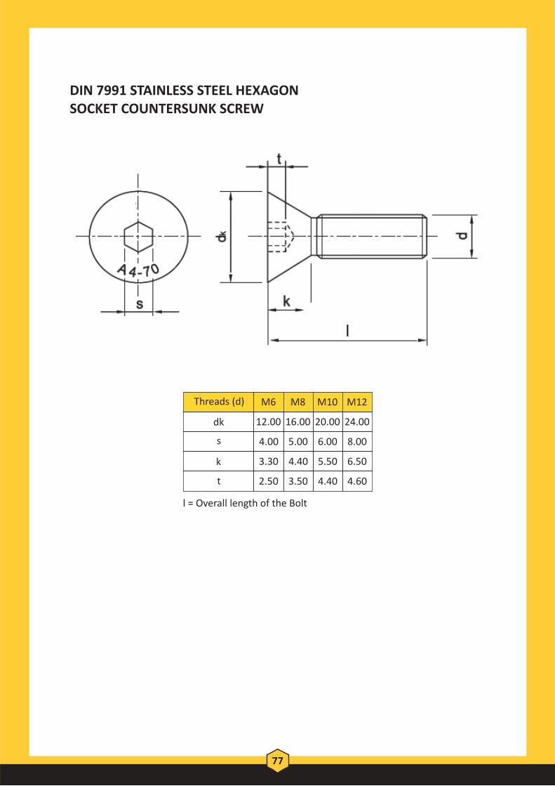
DIN 7991 STAINLESS STEEL HEXAGONSOCKET COUNTERSUNK SCREW
l = Overall length of the Bolt
dk 12.00 16.00 20.00 24.00
s 4.00 5.00 6.00 8.00
k 3.30 4.40 5.50 6.50
t 2.50 3.50 4.40 4.60
Threads (d) M6 M8 M10 M12
77

Standard Hex Nut, Heavy Hex Nut, Hex Coupling Nut, Nylon Lock Nut, Spring Nut, Dome Nut and Wing Nut
Standards:-• ASTM/ASME/BS/DIN/BS EN ISO /JIS
Material:-• Mild Steel, Carbon Steel, Alloy Steel & Stainless Steel.
Size Range:-• M6 to M64 in metric series• ¼" to 2-½" in imperial• Bigger sizes can be manufactured as per order.
Threads:-• UNC, 8UN, UNF, Metric Coarse and Metric Fine
Typical Grades & Standards:-• DIN 934 Class 4, 8, 10, 12, A270, A280, A470 and A480• ASTM A194/A194M Grades 2H, 2HM, 4L, 7L and 7LM• ASTM A563/563M Grades 8, 10S, A, B, C, D, DH, DH3
Ordering Information:-• Dimensions - Size.• Standard and Grade• Finish (Black, GI, Yellow, HDG, Cadmium, Nickel, PTFE etc)
NUTS
78
Thre
aded
Bar
&
Acc
esso
ry

HEAVY HEX NUTS TO DIN 934 (H=D)Material ASTM A194 Grade 2H/2HM/4L, 7L, 7LM
A194 HEAVY HEX BOLTS
Dia.(D) Thread Across Thickness weight
Pitch Flats AF (m) KG/100
M8 1.25 13 8 0.65
M10 1.5 17 10 1.45
M12 1.75 19 12 2.17
M14 2 22 14 3.13
M16 2 24 16 4.16
M18 2.5 27 18 6.20
M20 2.5 30 20 8.05
M22 2.5 32 22 9.85
M24 3 36 24 13.80
M27 3 41 27 20.65
M30 3.5 46 30 27.90
M33 3.5 50 33 36.00
M36 4.0 55 36 49.15
M39 4.0 60 39 42.75
M42 4.5 65 42 81.50
M45 4.5 70 45 100.00
M48 5.0 75 48 122.00
M52 5.0 80 52 152.50
M56 5.5 85 56 177.50
M64 6.0 95 64 247.50
M72 6.0 105 72 334.50
M76 6.0 110 76 380.00
79

HEAVY HEX NUTS TO ANSI B18.2.2Material ASTM A194 Grade 2H/2HM/4L, 7L, 7LM
A563M - 10S HEAVY HEX NUTS
A563-10S HEAVY HEX BOLTS
Threads ( d ) M12 M16 M20 M22 M24 M27 M30 M36
Across flat ( s ) Min 20.16 26.16 33.00 35.00 40.00 45.00 49.00 58.80Max 21.00 27.00 34.00 36.00 41.00 46.00 50.00 60.00
Acrosscorner ( e ) Min 22.78 29.56 37.29 39.55 45.20 50.85 55.37 66.44
Nut Thickness (m) Min 11.90 16.40 19.40 22.30 22.90 26.30 29.10 35.00Max 12.30 17.10 20.70 23.60 24.20 27.60 30.70 36.60
Bearing face Dia(dw) Min 19.20 24.90 31.40 33.30 38.00 42.80 46.60 55.90
80
Thre
aded
Bar
&
Acc
esso
ry

KG/100
A194 HEAVY HEX BOLTS
Dia.(D) Thread Across Thickness(m) weight
Pitch Flats AF
1/4" UNC 20 7/16" 1/4" 0.3
5/16" UNC 18 1/2" 5/16" 0.4
3/8" UNC 16 11/16" 3/8" 1.4
7/16" UNC 14 3/4" 3/16" 1.9
1/2" UNC 13 7/8" 1/2" 3.0
9/16" UNC 12 15/16" 9/6" 3.7
5/8" UNC 11 1.1/16" 5/8" 5.4
3/4" UNC 10 1.14" 3/4" 8.8
7/8" UNC 9 1.7/16" 7/8" 13.5
1" UNC 8 1.5/8" 1" 19.3
1.1/8" UNS 8 1.13/16" 1.1/8" 26.9
1.1/4" UNS 8 2" 1.1/4" 35.7
1.3/8" UNS 8 2.3/16" 1.3/8" 46.3
1.1/2" UNS 8 2.3/8" 1.1/2" 59.5
1.5/8" UNS 8 2.9/16" 1.5/8" 73.6
1.3/4" UNS 8 2.3/4" 1.3/4" 92.7
1.7/8" UNS 8 2.15/16" 1.7/8" 109.5
2" UNS 8 3.1/8" 2" 135.8
2.1/4" UNS 8 3.1/2" 2.1/4" 190.3
2.1/2" UNS 8 3.7/8" 2.1/4" 256
2.3/4" UNS 8 4.1/4" 2.3/4" 335
3" UNS 8 4.5/8" 3" 432
3.1/4" UNS 8 5" 3.1/4" 543
3.1/2" UNS 8 5.3/8" 3 1/2" 694
81

DIN 934 HEX NUTS
DIN 934 HEX NUTS
Threads (d) Across Across Nut flat (s) corner (e) thickness (m)
M6 10.00 11.05 6.00
M8 13.00 14.38 6.50
M10 17.00 18.90 8.00
M12 19.00 21.10 10.00
M16 24.00 26.75 13.00
M20 30.00 32.95 16.00
M24 36.00 39.55 19.00
M27 41.00 45.20 22.00
M30 46.00 50.85 24.00
M33 50.00 55.37 26.00
M36 55.00 60.79 29.00
M39 60.00 66.44 31.00
M42 65.00 71.30 34.00
M45 70.00 76.95 36.00
M48 75.00 82.60 38.00
M52 80.00 88.25 42.00
M56 85.00 93.56 45.00
M64 95.00 104.86 51.00
M72 105.00 116.16 58.00
82
Thre
aded
Bar
&
Acc
esso
ry

Plain Washers, Spring Lock Washers and Hardened Steel Washers
Standards:-
• ASTM/ASME/BS/DIN/BS EN ISO /JIS
Material:-
• Mild Steel, Carbon Steel, Alloy Steel & Stainless Steel.
Size Range:-
• M6 to M64 in metric series
• ¼” to 2-½” in imperial
• Bigger sizes can be manufactured as per order.
Typical Grades & Standards:-
• DIN 125/A
• DIN 127/B
• DIN 9021
• ASTM F436 and F436MAny other specific grade can be manufactured upon request with short lead times
Ordering information:-
• Dimensions – Size.
• Standard and Grade
• Finish (Black, GI, Yellow, HDG, Cadmium, Nickel, PTFE etc.)
WASHERS
83

DIN 125 FLAT WASHER
M6 6.40 12.00 1.60
M8 8.40 16.00 1.60
M10 10.50 20.00 2.00
M12 13.00 24.00 2.50
M16 17.00 30.00 3.00
M20 21.00 37.00 3.00
M24 25.00 44.00 4.00
M27 28.00 50.00 4.00
M30 31.00 56.00 4.00
M33 34.00 60.00 5.00
M36 37.00 66.00 5.00
M39 40.00 72.00 6.00
M42 43.00 78.00 7.00
M45 46.00 85.00 7.00
M48 50.00 92.00 8.00
M52 54.00 98.00 8.00
M56 58.00 105.00 9.00
M64 66.00 115.00 9.00
M72 74.00 125.00 10.00
washer size
Inner Diameter (d1)
Outer Diameter (d2)
Thickness (h)
84
Thre
aded
Bar
&
Acc
esso
ry

F436M WASHER
12 14.40 14.00 27.00 25.70 4.60 3.10
14 16.40 16.00 30.00 28.70 4.60 3.10
16 18.40 18.00 34.00 32.40 4.60 3.10
20 22.50 22.00 42.00 40.40 4.60 3.10
22 24.50 24.00 44.00 42.40 4.60 3.40
24 26.50 26.00 50.00 48.40 4.60 3.40
27 30.50 30.00 56.00 54.10 4.60 3.40
30 33.60 33.00 60.00 58.10 4.60 3.40
36 39.60 39.00 72.00 70.10 4.60 3.40
42 45.60 45.00 84.00 81.10 7.20 4.60
48 52.70 52.00 95.00 92.80 7.20 4.60
56 62.70 62.00 101.00 104.50 8.70 6.10
64 70.70 70.00 187.00 115.80 8.70 6.10
72 78.70 76.00 130.00 127.50 8.70 6.10
washer size
Inner Diameter (d1) Outer Diameter (d2) Thickness(h)
Max. Min.Min. Max. Min. Max.
85

PTFE (FLUOROPOLYMER Coating):-
Hot Dip Galvanizing:-
STD COMPONENTS
ASTM A153 Rolled/ Pressed/ steel/ Hardware
ASTM A641 Carbon Steel Wire(Nails/ Straples etc)
ASTM B695 Iron & Steel
ASTM A123 Iron & Steel Anchor Bolts, Fabricated Products
BS EN ISO 461 Heavy Zinc Deposit 388.1 to 76.2 microns
ELECTRO-DEPOSITED Zinc Plating:-
ASTM B633 Iron & Steel Products
BS 3382 PART 2 Bright Finish
BS 3382 PART 1 Semi- Bright FinishELECTRO-DEPOSITED Cadmium Plating:-
AMS 2416 SteelELECTRO-DEPOSITEDNickel Cadmium Plating:-
BS 3382 PART 3 & 4 Steel & Copper AlloyELECTRO-DEPOSITED Nickel & NickelPlus Chromium:-
XYLAN 1070Colour- Red, Medium Dark Blue, Green, Orange, Yellow, Black
XYLAN 1052 Blue
XYLAN 1424 Water Base Blue
xylan standard Aluminium "cermet" Coating
XYLAN Cobalt Blue 1514
Blue
MATERIAL FINISHES
86
Thre
aded
Bar
&
Acc
esso
ry

Mechanical properties per ISO 898-1(Externally Threaded Fasteners)
4.6 Low or Medium Carbon Steel
M5-M39 225 400 (58,000 PSI) B67 B99.5 240
Medium Carbon Steel: quenched & tempered
8.8
M5-M16 580 800 (116,000 PSI) C22 C32 640
M18-M39 600 830(120,000 PSI) C23 C34 660
Min. Max.
10.9
Alloy Steelquenched & tempered
M5-M39 830 1040 (150,800 PSI) C32 C39 940
12.9
Alloy Steel quenched & tempered
M16-M39 970 1220 (177,000 PSI) C39 C44 1100
Metric Property Class
MaterialSize
Range
Min. ProofStrength
MPA
Min. Tensile Strength MPA
Core Hardness Rockwell
Min. Yield Strength MPA
Grade Identification
Marking’
TECHNICAL INFORMATION
87

Mechanical properties per DIN 267 PART 4(Internally Threaded Fasteners)
Class 8Low to Medium Carbon Steel
800 C30
Class 10
Medium Carbon Steel; quenched & tempered
1000 C36
Class 12
Medium Carbon Steel; quenched & tempered
1200 C36
Property Class Typical Material Proof Stress MPACore Hardness Rockwell (max.)
Grade Identifications Marking
88
Thre
aded
Bar
&
Acc
esso
ry

DROP IN ANCHOR
89
DRAW IN ANCHOR
Product Code Size Drill Bit Anchor Length Thread Length
(B) ( C ) (D)
SE-DPA M6 M6 8 25 10
SE-DPA M8 M8 10 30 13
SE-DPA M10 M10 12 40 16
SE-DPA M12 M12 16 50 21
SE-DPA M16 M16 20 65 30
SE-DPA M20 M20 25 80 30
Product Code Size Shield Length
Hole Diameter
Length of Anchor
SE-DWA M6 M6 45 12 45
SE-DWA M8 M8 50 14 50
SE-DWA M10 M10 60 16 60
SE-DWA M12 M12 75 20 65
SE-DWA M16 M16 115 25 95
SE-DWA M20 M20 130 32 115

Duct Corner Piece
G - Clamp
ACCESSORY SERIES
90
Thre
aded
Bar
&
Acc
esso
ry

NOTES

Floo
r Dra
in
Floor Drain


Stainless Steel Floor Drains – Non Magnetic
SS FLOOR DRAINOUT 3PC GRADENON MAGNETIC(BODY + SCREWED GRATING + LID)
Techinical Discription:200mm x 200mm x 102mm Fits Inside 4”Pipe 150mm x 150mm x 102mm Fits Inside 4”Pipe 109mm x 109mm x 78mm Fits Inside 3”Pipe 79mm x 79mm x 51mm Fits Inside 2”Pipe
Techinical Discription:200mm x 200mm x 102mm Fits Inside 4”Pipe 150mm x 150mm x 102mm Fits Inside 4”Pipe 109mm x 109mm x 78mm Fits Inside 3”Pipe 79mm x 79mm x 51mm Fits Inside 2”Pipe63 mm x63 mm x38 mm Fits Inside 1.1/2”Pipe
SS FLOOR CLEANOUT 2PC. - NON MAGNETIC(BODY + LID)
Techinical Discription:150mm x 150mm x 102mm Fits Inside 4”Pipe 109mm x 109mm x 78mm Fits Inside 3”Pipe 79mm x 79mm x 51mm Fits Inside 2”Pipe63 mm x63 mm x38 mm Fits Inside 1.1/2”Pipe
Thumb Type
SS Floor Grating 2pc. - Non Magnetic (Body + Screwed Grating)
FLOOR DRAINS
91
Floo
r Dra
in

Shower Channel Drains
This channel drain is manufactured using the finest quality material in conformity with the international quality standards. The offered channel drain finds immense application in residential and commercial sectors. Available in multiple specifications, this is admired for the features like durable nature, high strength, dimensional accuracy, corrosion resistance, etc.
Overall Size: Overall Size: 915 x 105 x 83mm (36 x 4 x 3.1/4 Inch) 800 x 105 x 83mm (31.1/2 x 4 x 3.1/4 Inch)
Overall Size: Overall Size: 600 x 105 x 83mm (23.1/2 x 4 x 3.1/4 Inch) 460 x 105 x 83mm (18 x 4 x 3.1/4 Inch)
FLOOR DRAINS
92

FLOOR DRAINS
93
Floo
r Dra
in

FLOOR DRAINS
94

FLOOR DRAINS
95
Floo
r Dra
in

NOTES

Valv
es
Valves


GATE VALVE
96
Note:
Freezing Weather Precaution-Subsequent to testing a piping system, valves should
be in an open position to allow complete drainage.
Product Code Size L d H
Tums To Open In. mm In. mm In. mm In. mm
SE-105Q-065 2.5 65 7.5 190 2.5 64 11.4 289 8.80
SE-105Q-080 3.0 80 8.0 203 3.0 76 12.7 322 10.50
SE-105Q-100 4.0 100 9.0 229 4.0 102 13.5 342 13.75
SE-105Q-150 6.0 150 10.5 267 6.0 152 17.0 432 16.00
SE-105Q-200 8.0 200 11.5 292 8.0 203 20.4 519 17.50
SE-105Q-250 10.0 250 13.0 330 10.0 254 21.2 539 21.50
SE-105Q-300 12.0 300 14.0 356 12.0 305 26.5 672 25.50
105Q - 300PSI AWWA C509 Grooved-End Gate Valve
• Bolted Bonnet · Non-Rising Stem · Resilient · Wedge Grooved-End • 300 PS1/20.7 Bar Non-Shock Cold Working Pressure • Conforms to AWWA C509 • FBE Coated Interior and Exterior • Maximum Operating Temperature 185°F/85°C • FM Approved & UL/ULC Listed
Material SpecificationsPART SPECIFICATION1. Valve Body Ductile Iron ASTM A 536 2: Resilient Wedge Ductile Iron ASTM A 536 with EPDM Encapsulation 3. Wedge Nut Bronze ASTM B 584 UNS C83600 4. Stem Stainless Steel ASTM A 276 UNS S41000 5. Bonnet Gasket EPDM 6. Bonnet Screw Alloy Steel ASTM A 574M Zinc Plated 7. Bonnet Cast Iron ASTM A 126-B 8. Stem Primary O-Ring EPDM 9. Stem Thrust Washer Stainless Steel ASTM A 276 UNS S41 000 10. Gland Seal O-Ring EPDM 11. Stem Ring Wiper EPDM 12., Operating Nut Washer Carbon steel Zinc Plated 13. Operating Nut Screw Alloy Steel ASTM A 574M Zinc Plated 14. Square Operating Nut Cast Iron ASTM A 126-B 14A. Handwheel (Optional) Ductile Iron ASTM A 536 15. Stem Primary O-Ring EPDM 16. Stem Seal Bushing Brass ASTM B 16 UNS C36000
Valv
es

97
Note:
<> Freezing Weather Precaution-Subsequent to testing a piping system. valves should be
in an open position to allow complete drainage.
<> Flange: ANSI Class125f150. other flange dimensions are available.
Product Code Size L d H Tums To
Open In. mm In. mm In. mm In. mm
SE-108Q-065 2.5 65 7.5 190 2.5 64 11.4 289 8.80
SE-108Q-080 3.0 80 8.0 203 3.0 76 12.7 322 10.50
SE-108Q-100 4.0 100 9.0 229 4.0 102 13.5 342 13.75
SE-108Q-150 6.0 150 10.5 267 6.0 152 17.0 432 16.00
SE-108Q-200 8.0 200 11.5 292 8.0 203 20.4 519 17.50
SE-108Q-250 10.0 250 13.0 330 10.0 254 21.2 539 21.50
SE-108Q-300 12.0 300 14.0 356 12.0 305 26.5 672 25.50
108Q - 250PSI AWWA C509 Flanged X Grooved-End Gate
• Bolted Bonnet · Non-Rising Stem · Resilient Wedge · Flanged X Grooved-End • 250 PSI/17.2Bar Non-Shock Cold Working Pressure • Conforms to AWWA C509 • FBE Coated Interior and Exterior • Maximum Operating Temperature 185°F /85°C • FM Approved & UL/ULC Listed
Material Specifications PART SPECIFICATION 1. Valve Body Ductile Iron ASTM A 536 2. Resilient Wedge Ductile Iron ASTM A 536 with EPDM Encapsulation 3. Wedge Nut Bronze ASTM B 584 UNS C83600 4. Stem Stainless Steel ASTM A 276 UNS S41000 5. Bonnet Gasket EPDM6. Bonnet Screw Alloy Steel ASTM A 574M Zinc Plated 7. Bonnet Cast Iron ASTM A 126-B 8. Stem Primary a-Ring EPDM 9. Stem Thrust Washer Stainless Steel ASTM A 276 UNS S41000 10. Gland Seal O-Ring EPDM 11. Stem Ring Wiper EPDM 12. Operating Nut Washer Carbon steel Zinc Plated 13. Operating Nut Screw Alloy Steel ASTM A 574M Zinc Plated 14. Square Operating Nut Cast Iron ASTM A 126-B 14A. Handwheel (Optional) Ductile Iron ASTM A 536 15. Stem Primary a-Ring EPDM 16. Stem Seal Bushing Brass ASTM B 16 UNS C36000

135 - AWWA C509 300PSI Grooved-End Gate Valve
• Bolted Bonnet · Outside Screw and Yoke · Resilient Wedge · Grooved-End • 300 PS1/20.7 Bar Non-Shock Cold Working Pressure • Conforms to AWWA C509 • FBE Coated Interior and Exterior • Maximum Operating Temperature 185°F/85°C • FM Approved & UL/ULC Listed
Material Specifications PART SPECIFICATION 1. Valve Body Ductile Iron ASTM A 536 2. Resilient Wedge Ductile Iron ASTM A 536 with EPDM Encapsulation 3. Wedge Nut Bronze ASTM B 584 UNS C83600 4. Dowel Pin Stainless Steel ASTM A 276 UNS S42000 5. Stem Back Seat O.Ring EPDM 6. Bonnet Gasket EPDM 7. Bonnet Ductile Iron ASTM A 536 8. Stem Packing EPDM 9. Threaded Rod Carbon steel linc Plated 10. Gland Bushing Brass ASTM B 584 11. Gland Cast Iron ASTM A 126·B 12. Gland Nut Stainless Steel 18·8 13. Yoke Screw Alloy Steel ASTM A 574M Zinc Plated 14. Yoke Cast Iron ASTM A 126·B 15. Yoke Bushing Bronze ASTM B 584 16. Flat Point Set Screw Alloy Steel ASTM F 912M Black Oxide 17. Yoke Bushing Retainer Cast Iron ASTM A 126·B 18. Handwheel Ductile Iron ASTM A 536 19. Handwheel Nut Carbon steel line Plated 20. Hat Head Screw Carbon steel linc Plated 21. Stem Bronze ASTM B 150 UNS C61400 22. Bonnet Screw Alloy Steel ASTM A 574M line Plated
98
Note:
Freezing Weather Precaution-Scbsequent to testing a piping system.
valves should be in an open position to allow complete drainage.
Product Code
Size L d G H Open H Close Tums To Open In. mm In. mm In. mm In. mm In. mm In. mm
SE-135-065 2.5 65 7.5 190 2.5 64 7.9 200 17.8 453 14.9 378 8.8
SE-135-080 3.0 80 8.0 203 3.0 76 10.0 254 20.1 510 15.9 405 10.5
SE-135-100 4.0 100 9.0 229 4.0 102 10.0 254 22.4 568 16.6 422 13.8
SE-135-150 6.0 150 10.5 267 6.0 152 12.4 315 30.3 769 22.9 581 16.0
SE-135-200 8.0 200 11.5 292 8.0 203 14.8 375 37.8 960 28.5 724 17.5
SE-135-250 10.0 250 13.0 330 10.0 254 16.4 416 44.8 1139 34.5 877 21.5
SE-135-300 12.0 300 14.0 358 12.0 305 17.5 445 52.2 1326 39.9 1014 25.5
Valv
es

138 - 250PSI AWVVA C509 Flanged X Grooved-End Gate Valve
• Bolted Bonnet · Outside Screw and Yoke · Resilient Wedge · Flanged X Grooved-End • 250 PSI/17.2Bar Non-Shock Cold Working Pressure • Conforms to AWWA C509 • FBE Coated Interior and Exterior • Maximum Operating Temperature 185°F/85°C • FM Approved & UL/ULC Listed
Material Specifications PART SPECIFICATION 1. Valve Body Ductile Iron ASTM A 536 2. Resilient Wedge Ductile Iron ASTM A 536 with EPDM Encapsulation 3. Wedge Nut Bronze ASTM B 584 UNS C83600 4. Dowel Pin Stainless Steel ASTM A 276 UNS S42000 5. Stem Back Seat a-Ring EPDM 6. Bonnet Gasket EPDM 7. Bonnet Ductile Iron ASTM A 536 8. Stem Packing EPDM 9. Threaded Rod Carbon steel Zinc Plated 10. Gland Bushin9 Brass ASTM B 584 11. Gland Cast Iron ASTM A 126-B 12. Gland Nut Stainless Steel 18-8 13. Yoke Screw Alloy Steel ASTM A 574M Zinc Plated 14. Yoke Cast Iron ASTM A 126-B 15. Yoke Bushing Bronze ASTM B 584 16. Flat Point Set Screw Alloy Steel ASTM F 912M Black Oxide 17. Yoke Bushing Retainer Cast Iron ASTM A 126-B 18. Handwheel Ductile Iron ASTM A 536 19. Handwheel Nut Carbon steel Zinc Plated 20. Flat Head Screw Carbon steel Zinc Plated 21. Stem Bronze ASTM B 150 UNS C61400 22. Bonnet Screw Alloy Steel ASTM A 574M Zinc Plated
99
Note:
<> Freezing Weather Precaution-Subsequent to testing a piping system,
valves should be in an open position to allow complete drainage.
<> Flange: ANSI Class125/150, other flange dimensions are available.
Product Code
Size L d G H Open H Close Tums To Open In. mm In. mm In. mm In. mm In. mm In. mm
SE-138-065 2.5 65 7.5 190 2.5 64 7.9 200 17.8 453 14.9 378 8.8
SE-138-080 3.0 80 8.0 203 3.0 76 10.0 254 20.1 510 15.9 405 10.5
SE-138-100 4.0 100 9.0 229 4.0 102 10.0 254 22.4 568 16.6 422 13.8
SE-138-150 6.0 150 10.5 267 6.0 152 12.4 315 30.3 769 22.9 581 16.0
SE-138-200 8.0 200 11.5 292 8.0 203 14.8 375 37.8 960 28.5 724 17.5
SE-138-250 10.0 250 13.0 330 10.0 254 16.4 416 44.8 1139 34.5 877 21.5
SE-138-300 12.0 300 14.0 358 12.0 305 17.5 445 52.2 1326 39.9 1014 25.5

F909 - 300PSI AWWA C509 Flanged-End Gate Valve
• Bolted Bonnet • 300 PS1/20.7 Bar Non-Shock Cold Working Pressure • Conforms to AWWA C509 • FBE Coated Interior and Exterior • Maximum Operating Temperature 185°F / 85°F • FM Approved & UL/ULC Listed
Material Specification PART SPECIFICATION 1. Valve Body Ductile Iron ASTM A 536 2. Resilient Wedge Ductile Iron ASTM A 536 with EPDM Encapsulation 3. Wedge Nut Bronze ASTM B 584 UNS C83600 4. Stem Stainless Steel ASTM A 276 UNS S41000 5. Bonnet Gasket EPDM 6. Bonnet Screw Alloy Steel ASTM A 574M Zinc Plated 7. Bonnet Cast Iron ASTM A 126-B 8. Stem Primary a-Ring EPDM 9. Stem Thrust Washer Stainless Steel ASTM A 276 UNS S41 000 10. Gland Seal O-Ring EPDM 11. Stem Ring Wiper EPDM 12. Operating Nut Washer Carbon steel Zinc Plated 13. Operating Nut Screw Alloy Steel ASTM A 574M Zinc Plated 14. Square Operating Nut Cast Iron ASTM A 126-B 14A. Handwheel (Optional) Ductile Iron ASTM A 536 15. Stem Primary O-Ring EPDM 16. Stem Seal Bushing Brass ASTM B 16 UNS C36000
• Non-Rising Stem • Resilient Wedge • Flanged-End
100
Note:
<> Freezing Weather Prec in an open position to allow
<> Flange: ANSI Class12 FlowCom Mechanical
PSI AWWA C509 Flanged-End Gate Valve
Product Code
Size L d H Tums To Open In. mm In. mm In. mm In. mm
SE-F909-065 2.5 65 7.5 190 2.5 64 11.4 289 8.80
SE-F909-080 3.0 80 8.0 203 3.0 76 12.7 322 10.50
SE-F909-100 4.0 100 9.0 229 4.0 102 13.5 342 13.75
SE-F909-150 6.0 150 10.5 267 6.0 152 17.0 432 16.00
SE-F909-200 8.0 200 11.5 292 8.0 203 20.4 519 17.50
SE-F909-250 10.0 250 13.0 330 10.0 254 21.2 539 21.50
SE-F909-300 12.0 300 14.0 356 12.0 305 26.5 672 25.50
Valv
es

101
Note:
<> Freezing Weather Precaution-Subsequent to testing a piping system, valves should be
in an open position to allow complete drainage.
Product Code Size L D H d E Bolt Circle Flage
Holes Tums To
Open In. mm In. mm In. mm In. mm In. mm In. mm In. mm
SE-MJ909-080 3 80 8.0 203 7.7 196 12.7 322 3.1 80 4.9 126 6.19 157 4 10.8
SE-MJ909-100 4 100 10.0 254 9.1 232 13.5 344 3.9 100 6 153 7.5 191 4 13.0
SE-MJ909-150 6 150 11.5 292 11.1 283 17.4 441 5.9 150 8.1 206 9.5 241 6 15.7
SE-MJ909-200 8 200 11.5 292 13.4 340 20.8 529 7.9 200 10.3 261 11.75 298 6 17.3
SE-MJ909-250 10 250 13.0 330 15.7 400 24.2 614 9.8 250 12.3 313 14 356 8 21.4
SE-MJ909-300 12 300 14.0 356 18.0 456 27.6 700 11.8 300 14.4 367 16.25 413 8 25.3
AWWA C509 300PSI MJ909 Mechanical Joint Ends Gate Valve
• Bolted Bonnet Non-Rising Stem Resilient Wedge MJ End • 250 PS1/300PS1/17.2Bar Non-Shock Cold Working Pressure • CONFORMS TO AWWA C509 • Coating-Electrostatically Applied Fusion-Bonded Epoxy 0.2-0.5mm • Inside and Outside Meet or Exceeds AWWA C550 • Maximum Operating Temperature 160°F 171°C • FM Approved & UL/ULC Listed
Material Specifications PART SPECIFICATION
1. Valve Body Ductile Iron ASTM A 536 2. Resilient Wedge Ductile Iron ASTM A 536 with EPDM Encapsulation 3. Wedge Nut Bronze ASTM B 584 UNS C83600 4. Stem Bronze ASTM B 150 UNS C61400 5. Bonnet Gasket EPDM 6. Bonnet Screw Alloy Steel ASTM A 574M Zinc Plated 7. Bonnet Ductile Iron ASTM A 536 8. Stem Back Seat O-Ring EPDM 9. Stem Thrust Washer(Lower) Bronze ASTM B 584 UNS C83600 10. Stem Thrust Washer(Upper) Stainless Steel ASTM A 276 UNS S41000 11. Gland Seal O-Ring EPDM 12. Stem Seal Bushing Bronze ASTM B 584 UNS C83600 13. Stem Secondary O-Ring(2) EPDM 14. Gland Flange Ductile Iron ASTM A 536 15. Gland Flange Screw Alloy Steel ASTM A 574M Zinc Plated 16. Stem Ring Wiper EPDM 17. Square Operating Nut Cast Iron ASTM A 126-B 17A. Handweel (Optional) Ductile Iron ASTM A 536 18. Flat Washer Carbon Steel Zinc Plated 19. Screw Alloy Steel ASTM A 574M Zinc Plated
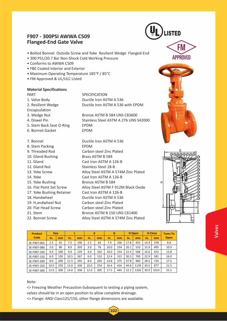
F907 - 300PSI AWWA C509 Flanged-End Gate Valve
• Bolted Bonnet Outside Screw and Yoke Resilient Wedge Flanged-End • 300 PS1/20.7 Bar Non-Shock Cold Working Pressure • Conforms to AWWA C509 • FBE Coated Interior and Exterior • Maximum Operating Temperature 185°F / 85°C • FM Approved & UL/ULC Listed
Material Specifications PART SPECIFICATION 1. Valve Body Ductile Iron ASTM A 536 2. Resilient Wedge Ductile Iron ASTM A 536 with EPDM Encapsulation 3. Wedge Nut Bronze ASTM B 584 UNS C83600 4. Dowel Pin Stainless Steel ASTM A 276 UNS S42000 5. Stem Back Seat O-Ring EPDM 6. Bonnet Gasket EPDM
7. Bonnet Ductile Iron ASTM A 536 8. Stem Packing EPDM 9. Threaded Rod Carbon steel Zinc Plated 10. Gland Bushing Brass ASTM B 584 11. Gland Cast Iron ASTM A 126-B 12. Gland Nut Stainless Steel 18-8 13. Yoke Screw Alloy Steel ASTM A 574M Zinc Plated 14. Yoke Cast Iron ASTM A 126-B 15. Yoke Bushing Bronze ASTM B 584 16. Flat Point Set Screw Alloy Steel ASTM F 912M Black Oxide 17. Yoke Bushing Retainer Cast Iron ASTM A 126-B 18. Handwheel Ductile Iron ASTM A 536 19. H,andwheel Nut Carbon steel Zinc Plated 20. Flat Head Screw Carbon steel Zinc Plated 21. Stem Bronze ASTM B 150 UNS C61400 22. Bonnet Screw Alloy Steel ASTM A 574M Zinc Plated
102
Note:
<> Freezing Weather Precaution-Subsequent to testing a piping system,
valves should be in an open position to allow complete drainage.
<> Flange: ANSI Class125/150, other flange dimensions are available.
Product Code
Size L d G H Open H Close Tums To Open In. mm In. mm In. mm In. mm In. mm In. mm
SE-F907-065 2.5 65 7.5 190 2.5 64 7.9 200 17.8 453 14.9 378 8.8
SE-F907-080 3.0 80 8.0 203 3.0 76 10.0 254 20.1 510 15.9 405 10.5
SE-F907-100 4.0 100 9.0 229 4.0 102 10.0 254 22.4 568 16.6 422 13.8
SE-F907-150 6.0 150 10.5 267 6.0 152 12.4 315 30.3 769 22.9 581 16.0
SE-F907-200 8.0 200 11.5 292 8.0 203 14.8 375 37.8 960 28.5 724 17.5
SE-F907-250 10.0 250 13.0 330 10.0 254 16.4 416 44.8 1139 34.5 877 21.5
SE-F907-300 12.0 300 14.0 358 12.0 305 17.5 445 52.2 1326 39.9 1014 25.5
Valv
es

VCG01 - 350PSI Grooved-End Swing Check Valve
• Installed in both Horizontal or Vertical Line with Upward Flow • Easier and Faster to Maintain and Install • Low Pressure Drop • EPDM non-stick leak tight sealing • All Stainless Steel Wetted Parts to Provide Superior Corrosion Resistance • FM Approved & UL/ULC Listed
Material Specifications PART SPECIFICATION
1. Body Ductile Iron ASTM A 536 2. Seat Bronze 3. Clapper Stainless Steel 304 4. Facing Seal EPDM Rubber 5. Clamping Ring Stainless Steel 304 6. Gasket EPDM Rubber 7. Spring Stainless Steel 304 8. Hinge Pin Stainless Steel 304 9. Bolt Stainless Steel 304 10. Locknut Stainless Steel 304 11. Plug 1/4" NPT Carbon Steel 12. Plug 1/2" NPT Carbon Steel
CHECK VALVE
103
Note:
<> Freezing Weather Precaution-Subsequent to testing a piping system, valves should be
in an open position to allow complete drainage.
Product Code Size OD A Weight
In mm mm In mm lbs kg
SE-VCG01-060 2 50 60.3 6.65 169 5.5 2.5
SE-VCG01-073 2 1/2 65 73 7.2 183 8.8 4
SE-VCG01-076 3 OD 65 76.1 7.2 183 8.8 4
SE-VCG01-089 3 80 88.9 7.8 198 13 6
SE-VCG01-114 4 100 114.3 8.85 218 20 9
SE-VCG01-140 5 1/2 OD 125 139.7 9.76 248 33 15
SE-VCG01-141 5 125 141.3 9.76 248 33 15
SE-VCG01-165 6 1/2 OD 150 165.1 10.63 270 42 19
SE-VCG01-168 6 150 168.3 10.63 270 42 19
SE-VCG01-219 8 200 219.1 12.8 325 77 35
SE-VCG01-273 10 250 273
SE-VCG01-324 12 300 323.9

Check Valve Performance Date
104
Note:
<> Freezing Weather Precaution-Subsequent to testing a piping system,
valves should be in an open position to allow complete drainage.
<> Flange: ANSI Class125/150, other flange dimensions are available.
CV
Where: Q = Flow rate (gallons per minute: GPM) = Pressure drop across valve (PSI) = Flow coefficient P
P= Q2
CV2
PV X C= Q
Nominal Size Pipe OD Cv
(Full Open)
Nominal Size Pipe OD
Cv (Full
Open)
Nominal Size Pipe OD
Cv (Full
Open) In mm mm In mm mm In mm mm
2 50 60.3 100 4 100 114.3 390 6 1/2 OD 150 165.1 1000
2 1/2" 65 733 140 5 1/2 OD 125 139.7 700 6 150 168.3 1000
3 OD 65 76.1 140 5 125 141.3 700 8 200 219.1 1800
3 80 88.9 250
Valv
es

105
Flange Standard:ASME 16.5 Class 150BS 4504 PN10 / Pn16AS 2129 Table D / Table E
Size A Weight
In mm In mm Lbs kg
2 DN50 6.65 169 5.5 2.5
2 1/2" DN65 7.20 183 8.8 4
3" DN80 7.80 198 13 6
4" DN100 8.58 218 20 9
5" DN125 9.78 248 33 15
6" DN150 10.63 270 42 19
8" DN200 12.80 325 77 35
10" DN250
12" DN300
350PSI VCF01 Flanged-End Swing Check Valve
• Installed in both Horizontal or Vertical Line with Upward Flow • Easier and Faster to Maintain and Install • Low Pressure Drop • EPDM non-stick leak tight sealing • All Stainless Steel Wetted Parts to Provide Superior Corrosion Resistance
Material Specifications PART SPECIFICATION 1. Body Ductile Iron ASTM A 536 2. Seat Bronze 3. Clapper Stainless Steel 304 4. Facing Seal EPDM Rubber 5. Clamping Ring Stainless Steel 304 6. Gasket EPDM Rubber 7. Spring Stainless Steel 304 8. Hinge Pin Stainless Steel 304 9. Bolt Stainless Steel 304 10. Locknut Stainless Steel 304 11. Plug 1/4" NPT Carbon Steel 12. Plug 1/2" NPT Carbon Steel

106
Part Number Size OD E F G H J K
In mm mm In mm In mm In mm In mm In mm In mm
SE-VBG01-073 21/2 65 73.0 3.85 98 2.40 61 11.22 285 2.91 74 3.54 90 2.13 54
SE-VBG01-076 3OD 65 76.1 3.85 98 2.40 61 11.22 285 2.91 74 3.54 90 2.13 54
SE-VBG01-089 3 80 88.9 3.85 98 2.87 73 12.20 310 2.91 74 3.54 90 2.13 54
SE-VBG01-114 4 100 114.3 4.56 116 3.86 98 14.17 360 2.91 74 3.54 90 2.13 54
SE-VBG01-140 5 ½ OD 125 139.7 5.86 149 4.80 122 15.35 390 2.91 74 3.54 90 2.13 54
SE-VBG01-141 5 125 141.3 5.86 149 4.80 122 15.35 390 2.91 74 3.54 90 2.13 54
SE-VBG01-165 6 ½ OD 150 165.1 5.86 149 5.75 146 16.73 425 2.91 74 3.54 90 2.13 54
SE-VBG01-168 6 150 168.3 5.86 149 5.75 146 16.73 425 2.91 74 3.54 90 2.13 54
SE-VBG01-219 8 200 219.1 5.27 134 7.72 196 19.41 493 2.91 74 3.54 90 2.13 54
SE-VBG01-273 10 250 273.0 6.30 160 9.57 243 22.91 582 3.90 99 3.98 101 3.03 77
Size L M N P Q R Wt.
In mm In mm In mm In mm In mm In mm Lbs. Kg.
21/2 5.87 149 5.27 134 3.78 96 2.95 75 5.90 150 3.35 85 20.9 9.5
3OD 5.87 149 5.27 134 3.78 96 2.95 75 5.90 150 3.35 85 21.4 9.7
3 5.87 149 5.63 143 4.13 105 3.54 90 5.90 150 3.82 97 22 10
4 7.68 195 6.81 173 5.31 135 4.33 110 5.90 150 4.88 124 24.7 11.2
5 ½ OD 7.68 195 7.20 183 5.83 148 5.00 127 5.90 150 6.10 155 27.5 12.5
5 7.68 195 7.20 183 5.83 148 5.00 127 5.90 150 6.10 155 27.5 12.5
6 ½ OD 7.68 195 8.00 203 6.50 165 5.71 145 5.90 150 7.20 183 37 16.8
6 7.68 195 8.00 203 6.50 165 5.71 145 5.90 150 7.20 183 41.4 18.8
8 7.68 195 9.53 242 8.03 204 6.89 175 9.84 250 9.29 236 48.7 22.1
10 9.49 241 11.42 290 9.65 245 8.27 210 11.8 300 11.38 289 83.7 38
Pn25 VBG01 H Grooved-End Butterfly Valve
• • NSF Certified Polymide Coated Ductile Iron body for Excellent Protection • Elastomer Encapsulated Disc with Outstanding Flow Characteristics • Extended Neck • Low Torque Operation • Options of Double Internal Supervisory Switches
Material Specifications Part Specification
1 Upper Stem Stainless Steel ASTM A 276 Type 4202 Upper Bearing PTFE Bronze Sintered on Steel3 O-Ring EPDM4 Body Ductile Iron ASTM A 536, Polymide Coated5 Disc Ductile Iron ASTM A 536 with EPDM Encapsulation6 Lower Bearing PTFE Bronze Sintered on Steel7 Lower Stem Stainless Steel ASTM A 276 Type 4208 Dust Plug PVC9 Name Plate Stainless Steel10 Gear Operator Cast Iron and Steel11 Indicator Flag Cast Iron12 Handwheel Cast Iron
FM Approved Gear Operator for both Indoor or Outdoor use
Valv
es

107
Part Size OD E F G H J K
Number In. mm mm In. mm In. mm In. mm In. mm In. mm In. mm
SE-VBG01-073 2 1/2 65 73.0 3.85 98 2.40 61 11.22 285 2.91 74 3.54 90 2.13 54
SE-VBG01-076 3OD 65 76.1 3.85 98 2.40 61 11.22 285 2.91 74 3.54 90 2.13 54
SE-VBG01-089 3 80 88.9 3.85 98 2.87 73 12.2 310 2.91 74 3.54 90 2.13 54
SE-VBG01-114
4
100
114.3
4.56
116
3.86 98 14.17 360 2.91 74 3.54 90 2.13 54
SE-VBG01-140
5 1/2OD
125
139.7
5.86
149
4.80 122 15.35 390 2.91 74 3.54 90 2.13 54
SE-VBG01-141
5
125
141.3
5.86
149
4.80 122 15.35 390 2.91 74 3.54 90 2.13 54
SE-VBG01-165
6 1/2OD
150
165.1
5.86
149
5.75 146 16.73 425 2.91 74 3.54 90 2.13 54
SE-VBG01-168
6
150
168.3
5.86
149
5.75 146 16.73 425 2.91 74 3.54 90 2.13 54
SE-VBG01-219
8
200
219.1
5.27
134
7.72 196 19.41 493 2.91 74 3.54 90 2.13 54
SE-VBG01-273
10
250
273.0
6.30
9.57
9.57 243 22.76 578 3.90 99 3.98 101 3.03 77
Size L M N P Q R Wt.
In. In. mm In. mm In. mm In. mm In. mm In. mm Lbs. Kg.
2 1/2 7.68 195 5.27 134 3.78 96 2.95 75 5.90 150 3.35 85 17.4 7.9
3OD 7.68 195 5.27 134 3.78 96 2.95 75 5.90 150 3.35 85 17.6 8.0
3 7.68 195 5.63 143 4.13 105 3.54 90 5.90 150 3.82 97 18.9 8.6
4 7.68 195 6.81 173 5.31 135 4.33 110 5.90 150 4.88 124 23.4 10.6
5 1/2OD
7.68
195
7.32
186
5.83
148
5.00 127 5.90 150 6.10 155 31.3 14.2
5
7.68
195
7.32
186
5.83
148
5.00 127 5.90 150 6.10 155 31.3 14.2
6 1/2OD
7.68
195
8.00
203
6.50
165
5.71 145 5.90 150 7.20 183 34.8 15.8
6
7.68
195
8.00
203
6.50
165
5.71 145 5.90 150 7.20 183 35.5 16.1
8 8.03 204 9.53 242 8.03 204 6.89 175 9.84 250 9.29 236 50.5 22.9
10
9.49
241
11.42
290
9.65
245
8.27 210 11.80 300 11.38 289 86.9 39.4
VBG01 - 300PSI Grooved-End Butterfly Valve
VBG01 C - 300PSI Grooved-End Butterfly Valve(CLOSE)
• • NSF Certified Polymide Coated Ductile Iron body for Excellent Protection • Elastomer Encapsulated Disc with Outstanding Flow Characteristics • Extended Neck • Low Torque Operation • Options of Double Internal Supervisory Switches • FM Approved & UL/ULC Listed
Material Specifications
Part Specification
1 Upper Stem Stainless Steel ASTM A 276 Gr. 420
2 Upper Bearing PTFE Bronze Sintered on Steel
3 O-Ring Nitrile
4 Body Ductile Iron ASTM A 396, Polymide Coated
5 Disc Ductile Iron ASTM A 395 with EPDM Encapsulation
6 Lower Bearing PTFE Bronze Sintered on Steel
7 Lower Stem Stainless Steel ASTM A 276 Gr. 420
8 Dust Plug PVC
9 Name Plate Stainless Steel
10 Gear Operator Cast Iron and Steel
11 Indicator Flag Cast Iron
12 Handwheel Cast Iron
Approved Gear Operator for both Indoor or Outdoor use

108
Butterfly Valve Performance Date
Formulas for Cv Values
Nominal Size Pipe O.D. Cv (Full Open)In. mm mm
2 1/2 65 73 221
3OD 65 76.1 221
3
80
88.9 324
4
100
114.3 670
51/2 OD
125
139.7 1200
5
125
141.3 1200
6 1/2 OD
150
165.1 1934
6
150
168.3 1934
8
200
219.1 3874
10
250
273 5995
Valv
es

109
Part Number Size OD E F G
In
mm
mm
In
mm
In
mm In mm
SE-VBG02-073
21/2
65
73.0
3.85
98
2.40
61
7.32 186
SE-VBG02-076
3OD
65
76.1
3.85
98
2.40
61
7.32 186
SE-VBG02-089
3
80
88.9
3.85
98
2.87
73
8.27 210
SE-VBG02-114
4
100
114.3
4.56
116
3.86
98
10.2 260
SE-VBG02-140
5 ½ OD
125
139.7
5.86
149
4.80
122
11.4 290
SE-VBG02-141
5
125
141.3
5.86
149
4.80
122
11.4 290
SE-VBG02-165
6 ½ OD
150
165.1
5.86
149
5.75
146
12.8 325
SE-VBG02-168
6
150
168.3
5.86
149
5.75
146
12.8 325
SE-VBG02-219 8 200 219.1 5.27 134 7.72 196 15.9 404
SE-VBG02-273 10 250 273.0 6.30 160 9.57 243 18.9 480
Size L
N
P
R
Wt.
In
mm
In
mm
In
mm
In
mm
Lbs. Kg.
21/2 10.2
260
3.78
96
2.95
75
3.35
85
12.1 5.5
3OD 10.2
260
3.78
96
2.95
75
3.35
85
12.6 5.7
3 10.2
260
4.13
105
3.54
90
3.82
97
13.2 6
4 10.2
260
5.31
135
4.33
110
4.88
124
15.9 7.2
5 ½ OD
10.2
260
5.83
148
5.00
127
6.10
155
18.7 8.5
5 10.2
260
5.83
148
5.00
127
6.10
155
18.7 8.5
6 ½ OD
10.2
260
6.50
165
5.71
145
7.20
183
28.2 12.8
6 10.2
260
6.50
165
5.71
145
7.20
183
32.6 14.8
8 12.8
325
8.03
204
6.89
175
9.29
236
35.5 16.1
10 12.8
325
9.65
245
8.27
210
11.38
289
66
30
300PSI VBG02 Grooved-End Butterfly Valve
• Both Gear Operator or Lever Handle Available for Indoor or Outdoor use • Epoxy Coated Ductile Iron body for Excellent Protection • Elastomer Encapsulated Disc with Outstanding Flow Characteristics • Low Torque Operation • Options of Double Internal Supervisory Switches for Gear Operator
Material Specifications Part Specification
1 Upper Stem Stainless Steel ASTM A 276 Type 4202 Upper Bearing PTFE Bronze Sintered on Steel3 O-Ring Nitrile4 Body Ductile Iron ASTM A 536, Epoxy Coated5 Disc Ductile Iron ASTM A 536 with EPDM Encapsulation6 Lower Bearing PTFE Bronze Sintered on Steel7 Lower Stem Stainless Steel ASTM A 276 Type 4208 Dust Plug PVC9 Name Plate Stainless Steel10 Pin Steel11 Plate Steel12 Handle Steel

110
300PSI VSG01 Grooved-End Y Type Strainer
• • Easier and Faster to Maintain and Install • Low Pressure Drop
Material Specifications 1. Body: Ductile Iron ASTM A 536
Standard Surface Finish: FBE coated interior and exterior Standard Color: Red RAL3000 I Blue RAL5015 Option: Hot dip galvanized
2. Screen: Stainless Steel 304, Perforated metal Standard: 2 - 3"(DN50 - 80): 0.062"(1.6mm) diameter perforations.
4 - 12"(DN1 00 - 300): 0.125"(3.2mm) diameter perforations. Option: 2 -12"(DN50 - 300): 0.315"(8mm) diameter perforations.
Other perforation available upon request
3. Grooved Coupling: Housing: Material: Ductile Iron ASTM A 536
Standard Surface Finish: Hot dip galvanized Other material or finish available upon request
Rubber Gaskets: Standard: Grade "E" EPDM (Color code: Green stripe) Temperature range -30°F to +230°F (-34°C to +110°C).
Recommended for cold and hot water service within the specified temperature range plus a variety of dilute acids, oil-free air and many chemical services. NOT
RECOMMENDED FOR PETROLEUM SERVICES.Option: Grade "T" Nitrile (Color code: Orange stripe) Temperature range -20°F to +180°F (-29°C to +82°C). Recommended for petroleum products, air with oil vapors, vegetable and mineral oils within the specified temperature range. Not recommended for hot water services over +150°F (+66°C) or for hot dry air over +140°F (+60°C). Other material available upon request
Bolts/Nuts: Heat treated carbon steel zinc electroplated to ASTM B-633, track head conforming to physical properties of ASTMA-183 minimum tensile 110,000 psil758340 kPa.
4. Grooved Cap: Ductile Iron ASTM A 536 Standard Surface Finish: Hot dip galvanized, Other material or finish available upon request
5. Plug: Malleable Iron ASTM A 197/ A 47 Standard Surface Finish: Hot dip galvanized Threaded: NPT pipe threaded, Other threaded available upon request
Installed in both Horizontal or Vertical Line with Upward Flow
Valv
es

111
300PSI VSG01 Grooved-End Y Type Strainer
Y Type Strainer Performance Date
Part Number Size OD A B D E F G Plug Weight
In mm mm In mm In mm In mm In mm In mm In mm In lbs kg
SE-VSG01-060
2
50
60.3
9.75
248
7.00
178
7.00
178
8.54
217
3.50 89 13.58 345 1/2 10.0 4.5
SE-VSG01-073 2 1/2
65
73.0
10.75
273
7.75
197
7.83
199
9.32
237
4.13 105 15.04 382 1/2 14.0 6.4
SE-VSG01-076 2 1/2
65
76.1
10.75
273
7.75
197
7.87
200
9.32
237
4.13 105 15.04 382 1/2 14.0 6.4
SE-VSG01-089
3
80
88.9
11.75
299
8.50
216
8.50
216
10.10
258
4.75 121 16.26 413 3/4 20.0 9.1
SE-VSG01-114
4
100
114.3
14.25
362
10.50
267
10.87
276
12.72
323
6.25 159 21.30 541 1 32.0 14.5
SE-VSG01-140
5
125
139.7
16.50
419
12.50
318
12.75
324
14.36
365
7.88 200 23.43 595 1 50.0 22.7
SE-VSG01-141
5
125
141.3
16.50
419
12.50
318
12.75
324
14.36
365
7.88 200 23.43 595 1 50.0 22.7
SE-VSG01-165
6
150
165.1
18.50
470
14.00
356
13.82
351
16.06
408
9.25 235 26.61 676 1 1/4 72.0 32.7
SE-VSG01-168
6
150
168.3
18.50
470
14.00
356
13.90
353
16.06
408
9.25 235 26.61 676 1 1/4 72.0 32.7
SE-VSG01-219
8
200
219.1
24.00
610
18.00
457
17.76
451
20.31
516
12.38 315 34.09 866 1 1/2 125.0 56.7
SE-VSG01-273 10 250 273.0
SE-VSG01-324 12 300 323.9

Inst
alla
tion
&
Tes
ting
Installation & Testing


INSTALLATION INSTRUCTION
CLEVIS HANGER
112
Inst
alla
tion
&
Tes
ting

SPRINKLER HANGER
PIPE HANGER WITH EPDM LINING
113

RISER CLAMP
114
Inst
alla
tion
&
Tes
ting

U STRAP
115

PIPE ROLLER CHAIR
ADJUSTABLE ROLLER CHAIR
116
Inst
alla
tion
&
Tes
ting

CLEVIS HANGER
TESTING OF PRODUCT
SPRINKLER HANGER
117

PIPE HANGER WITH EPDM LINING
RISER CLAMP
118
Inst
alla
tion
&
Tes
ting

U STRAP
119