Embed Size (px)
Citation preview

Driver’s Manual
CENTURY CLASS S/T®& CORONADO
STI-411-2
A24-01036-000

IntroductionThis manual provides information needed to operateand understand the vehicle and its components.More detailed information is contained in the Owner’sWarranty Information for North America booklet, andin the vehicle’s workshop and maintenance manuals.
Custom-built Freightliner vehicles are equipped withvarious chassis and cab components. Not all of theinformation contained in this manual applies to everyvehicle. For details about components in your ve-hicle, refer to the chassis specification pages in-cluded in all new vehicles and to the vehicle specifi-cation decal, located inside the vehicle.
For your reference, keep this manual in the vehicleat all times.
IMPORTANT: Descriptions and specifications in thismanual were in effect at the time of printing. Freight-liner Trucks reserves the right to discontinue modelsand to change specifications or design at any timewithout notice and without incurring obligation. De-scriptions and specifications contained in this publi-cation provide no warranty, expressed or implied,and are subject to revisions and editions without no-tice.
Environmental Concerns andRecommendationsWhenever you see instructions in this manual to dis-card materials, you should first attempt to reclaimand recycle them. To preserve our environment, fol-low appropriate environmental rules and regulationswhen disposing of materials.
Event Data RecorderThis vehicle is equipped with one or more devicesthat record specific vehicle data. The type andamount of data recorded varies depending on howthe vehicle is equipped (such as the brand of engine,if an air bag is installed, or if the vehicle features acollision avoidance system, etc.).
This vehicle is equipped with an event data recorder(EDR). The main purpose of an EDR is to recorddata in certain crash or near-crash situations, suchas air bag deployment or hitting a road obstacle, thatwill assist in understanding how a vehicle’s systemsperformed. The EDR is designed to record data re-
lated to vehicle dynamics and safety systems for ap-proximately 60 seconds. This data can help providea better understanding of the circumstances in whichcrashes and injuries occur. Data recorded includesthe following items:
• how various systems in the vehicle were oper-ating
• engine system information
• how far (if at all) the driver was depressing theaccelerator
• if the driver was depressing the brake pedal
• how fast the vehicle was traveling
NOTE: Data is not recorded by the EDR undernormal driving conditions. Personal data suchas name, gender, age, and crash location arenot recorded. However, other parties such aslaw enforcement could combine the EDR datawith the type of personally identifying data rou-tinely acquired during a crash investigation.
To read data recorded by an EDR, special equipmentis required, and access to the vehicle or the EDR isneeded. In addition to the vehicle manufacturer, otherparties that have the special equipment, such as lawenforcement, can read the information if they haveaccess to the vehicle or the EDR.
Customer Assistance CenterHaving trouble finding service? Call the CustomerAssistance Center at 1-800-385-4357 or 1-800-FTL-HELP. Call night or day, weekdays or weekends, fordealer referral, vehicle information, breakdown coor-dination, or Fleetpack assistance. Our people areknowledgeable, professional, and committed to fol-lowing through to help you keep your truck moving.
Reporting Safety DefectsIf you believe that your vehicle has a defect whichcould cause a crash or could cause injury ordeath, you should immediately inform the NationalHighway Traffic Safety Administration (NHTSA) inaddition to notifying Daimler Trucks North AmericaLLC.
If the NHTSA receives similar complaints, it mayopen an investigation, and if it finds that a safetydefect exists in a group of vehicles, it may order a
Foreword
STI-411-2 (11/14)A24-01036-000
Printed in U.S.A.
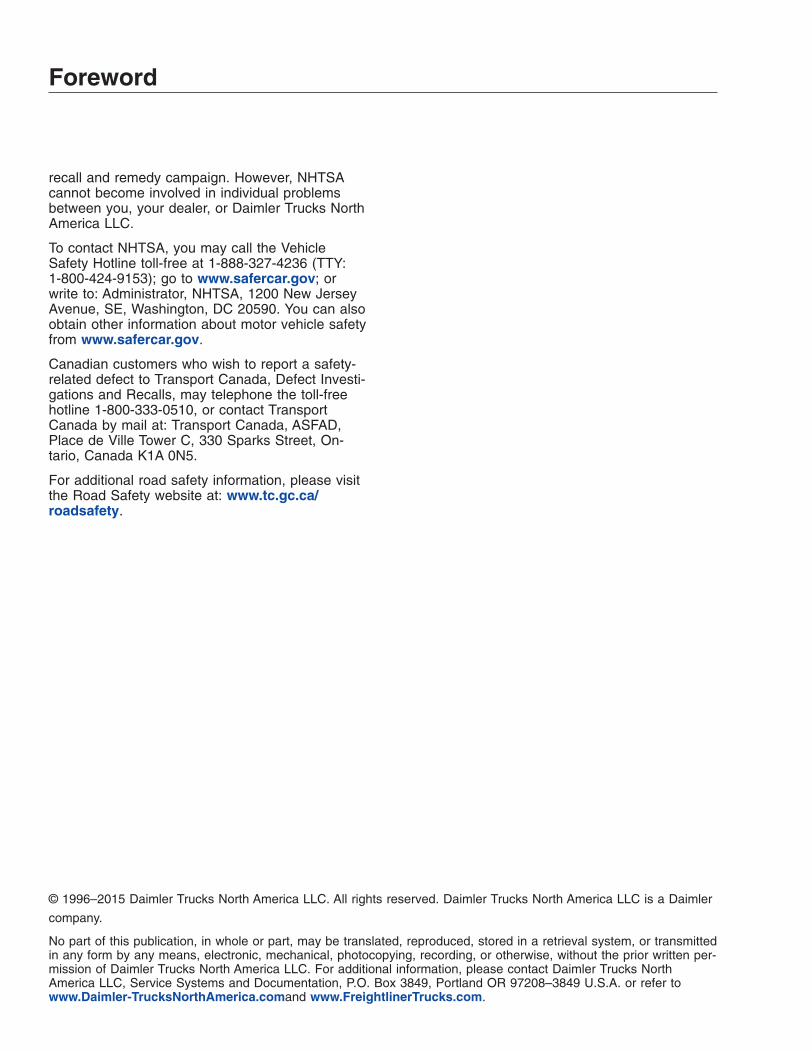
recall and remedy campaign. However, NHTSAcannot become involved in individual problemsbetween you, your dealer, or Daimler Trucks NorthAmerica LLC.
To contact NHTSA, you may call the VehicleSafety Hotline toll-free at 1-888-327-4236 (TTY:1-800-424-9153); go to www.safercar.gov; orwrite to: Administrator, NHTSA, 1200 New JerseyAvenue, SE, Washington, DC 20590. You can alsoobtain other information about motor vehicle safetyfrom www.safercar.gov.
Canadian customers who wish to report a safety-related defect to Transport Canada, Defect Investi-gations and Recalls, may telephone the toll-freehotline 1-800-333-0510, or contact TransportCanada by mail at: Transport Canada, ASFAD,Place de Ville Tower C, 330 Sparks Street, On-tario, Canada K1A 0N5.
For additional road safety information, please visitthe Road Safety website at: www.tc.gc.ca/roadsafety.
© 1996–2015 Daimler Trucks North America LLC. All rights reserved. Daimler Trucks North America LLC is a Daimler
company.
No part of this publication, in whole or part, may be translated, reproduced, stored in a retrieval system, or transmittedin any form by any means, electronic, mechanical, photocopying, recording, or otherwise, without the prior written per-mission of Daimler Trucks North America LLC. For additional information, please contact Daimler Trucks NorthAmerica LLC, Service Systems and Documentation, P.O. Box 3849, Portland OR 97208–3849 U.S.A. or refer towww.Daimler-TrucksNorthAmerica.comand www.FreightlinerTrucks.com.
Foreword
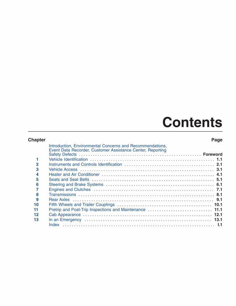
ContentsChapter Page
Introduction, Environmental Concerns and Recommendations,Event Data Recorder, Customer Assistance Center, ReportingSafety Defects . . . . . . . . . . . . . . . . . . . . . . . . . . . . . . . . . . . . . . . . . . . . . . . . . . . . . Foreword
1 Vehicle Identification . . . . . . . . . . . . . . . . . . . . . . . . . . . . . . . . . . . . . . . . . . . . . . . . . . . . . . 1.12 Instruments and Controls Identification . . . . . . . . . . . . . . . . . . . . . . . . . . . . . . . . . . . . . . . 2.13 Vehicle Access . . . . . . . . . . . . . . . . . . . . . . . . . . . . . . . . . . . . . . . . . . . . . . . . . . . . . . . . . . 3.14 Heater and Air Conditioner . . . . . . . . . . . . . . . . . . . . . . . . . . . . . . . . . . . . . . . . . . . . . . . . . 4.15 Seats and Seat Belts . . . . . . . . . . . . . . . . . . . . . . . . . . . . . . . . . . . . . . . . . . . . . . . . . . . . . 5.16 Steering and Brake Systems . . . . . . . . . . . . . . . . . . . . . . . . . . . . . . . . . . . . . . . . . . . . . . . 6.17 Engines and Clutches . . . . . . . . . . . . . . . . . . . . . . . . . . . . . . . . . . . . . . . . . . . . . . . . . . . . 7.18 Transmissions . . . . . . . . . . . . . . . . . . . . . . . . . . . . . . . . . . . . . . . . . . . . . . . . . . . . . . . . . . . 8.19 Rear Axles . . . . . . . . . . . . . . . . . . . . . . . . . . . . . . . . . . . . . . . . . . . . . . . . . . . . . . . . . . . . . 9.1
10 Fifth Wheels and Trailer Couplings . . . . . . . . . . . . . . . . . . . . . . . . . . . . . . . . . . . . . . . . . 10.111 Pretrip and Post-Trip Inspections and Maintenance . . . . . . . . . . . . . . . . . . . . . . . . . . . . 11.112 Cab Appearance . . . . . . . . . . . . . . . . . . . . . . . . . . . . . . . . . . . . . . . . . . . . . . . . . . . . . . . . 12.113 In an Emergency . . . . . . . . . . . . . . . . . . . . . . . . . . . . . . . . . . . . . . . . . . . . . . . . . . . . . . . 13.1
Index . . . . . . . . . . . . . . . . . . . . . . . . . . . . . . . . . . . . . . . . . . . . . . . . . . . . . . . . . . . . . . . . . . I.1

1
Vehicle IdentificationVehicle Specification Decal . . . . . . . . . . . . . . . . . . . . . . . . . . . . . . . . . . . . . . . . . . . . . . . . . . . . . . . . . 1.1Federal Motor Vehicle Safety Standard (FMVSS) Labels . . . . . . . . . . . . . . . . . . . . . . . . . . . . . . . . . 1.1Canadian Motor Vehicle Safety Standard (CMVSS) Labels . . . . . . . . . . . . . . . . . . . . . . . . . . . . . . . . 1.1Tire and Rim Labels . . . . . . . . . . . . . . . . . . . . . . . . . . . . . . . . . . . . . . . . . . . . . . . . . . . . . . . . . . . . . . . 1.2EPA Emission Control . . . . . . . . . . . . . . . . . . . . . . . . . . . . . . . . . . . . . . . . . . . . . . . . . . . . . . . . . . . . . 1.2
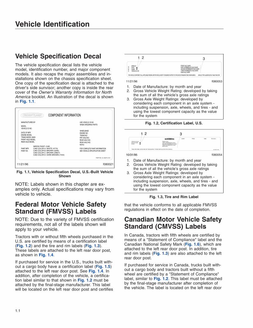
Vehicle Specification DecalThe vehicle specification decal lists the vehiclemodel, identification number, and major componentmodels. It also recaps the major assemblies and in-stallations shown on the chassis specification sheet.One copy of the specification decal is attached to thedriver’s side sunvisor; another copy is inside the rearcover of the Owner’s Warranty Information for NorthAmerica booklet. An illustration of the decal is shownin Fig. 1.1.
NOTE: Labels shown in this chapter are ex-amples only. Actual specifications may vary fromvehicle to vehicle.
Federal Motor Vehicle SafetyStandard (FMVSS) LabelsNOTE: Due to the variety of FMVSS certificationrequirements, not all of the labels shown willapply to your vehicle.
Tractors with or without fifth wheels purchased in theU.S. are certified by means of a certification label(Fig. 1.2) and the tire and rim labels (Fig. 1.3).These labels are attached to the left rear door post,as shown in Fig. 1.4.
If purchased for service in the U.S., trucks built with-out a cargo body have a certification label (Fig. 1.5)attached to the left rear door post. See Fig. 1.4. Inaddition, after completion of the vehicle, a certifica-tion label similar to that shown in Fig. 1.2 must beattached by the final-stage manufacturer. This labelwill be located on the left rear door post and certifies
that the vehicle conforms to all applicable FMVSSregulations in effect on the date of completion.
Canadian Motor Vehicle SafetyStandard (CMVSS) LabelsIn Canada, tractors with fifth wheels are certified bymeans of a "Statement of Compliance" label and theCanadian National Safety Mark (Fig. 1.6), which areattached to the left rear door post. In addition, tireand rim labels (Fig. 1.3) are also attached to the leftrear door post.
If purchased for service in Canada, trucks built with-out a cargo body and tractors built without a fifthwheel are certified by a "Statement of Compliance"label, similar to Fig. 1.2. This label must be attachedby the final-stage manufacturer after completion ofthe vehicle. The label is located on the left rear door
f08002111/21/96
USE VEHICLE ID NO.WHEN ORDERING PARTS
WHEELBASEENGINE NO.TRANS NO.FRT AXLE NO.REAR AXLE NO.REAR AXLE NO.RATIO
FOR COMPLETE PAINT INFORMATIONSEE VEHICLE SPECIFICATION SHEET
MANUFACTURED BY
MODELVEHICLE ID NO.
DATE OF MFRENGINE MODELTRANS MODEL MAINFRONT AXLE MODELREAR AXLE MODEL
PAINT MFRPAINT NO.
PART NO. 24−00273−010
COMPONENT INFORMATION
IMRON PAINT−CABCAB COLOR A: WHITE (4775)CAB COLOR B: BROWN (3295)CAB COLOR C: BROWN (29607)CAB COLOR D: DARK BROWN (7444)
Fig. 1.1, Vehicle Specification Decal, U.S.-Built VehicleShown
11/21/96 f080053
1 2 3
1. Date of Manufacture: by month and year2. Gross Vehicle Weight Rating: developed by taking
the sum of all the vehicle’s gross axle ratings3. Gross Axle Weight Ratings: developed by
considering each component in an axle system -including suspension, axle, wheels, and tires - andusing the lowest component capacity as the valuefor the system
Fig. 1.2, Certification Label, U.S.
f080054
24−00273−040TIRES AND RIMS LISTED ARE NOT NECESSARILY THOSE INSTALLED ON THE VEHICLE.
VEHICLE ID NO.DATE OF MFRGVWR
FRONT AXLEFIRST INTERMEDIATE AXLESECOND INTERMEDIATE AXLETHIRD INTERMEDIATE AXLEREAR AXLE
GAWR TIRES RIMS PSI COLD
1 2 3
10/31/95
1. Date of Manufacture: by month and year2. Gross Vehicle Weight Rating: developed by taking
the sum of all the vehicle’s gross axle ratings3. Gross Axle Weight Ratings: developed by
considering each component in an axle system -including suspension, axle, wheels, and tires - andusing the lowest component capacity as the valuefor the system
Fig. 1.3, Tire and Rim Label
Vehicle Identification
1.1

post, and certifies that the vehicle conforms to allapplicable CMVSS regulations in effect on the dateof completion.
Tire and Rim LabelsTire and rim labels certify suitable tire and rim combi-nations that can be installed on the vehicle, for thegiven gross axle weight rating. Tires and rims in-stalled on the vehicle at the time of manufacture mayhave a higher load capacity than that certified by thetire and rim label. If the tires and rims currently onthe vehicle have a lower load capacity than thatshown on the tire and rim label, then the tires andrims determine the load limitations on each of theaxles. See Fig. 1.3.
EPA Emission ControlVehicle Noise Emission Control LabelA vehicle noise emission control label (Fig. 1.7) isattached either to the left side of the dashboard or tothe top-right surface of the frontwall between thedash and the windshield.
IMPORTANT: Certain Freightliner incompletevehicles may be produced with incomplete noisecontrol hardware. Such vehicles will not have avehicle noise emission control information label.For such vehicles, it is the final-stage manufac-turer’s responsibility to complete the vehicle inconformity to U.S. EPA regulations (40 CFR Part205) and label it for compliance.
EPA07 Exhaust EmissionsRegulationsTo meet January 2007 emissions regulations, en-gines manufactured after January 1, 2007, areequipped with an emission aftertreatment device.There is a warning label on the driver’s sunvisor, ex-plaining important new warning indicators in thedriver’s message display, that pertain to the after-treatment system. See Fig. 1.8.
1
2
11/01/95 f601086
1. Tire and Rim Labels 2. Certification Label
Fig. 1.4, Labels Location
09/28/98 f080023
Fig. 1.5, Incomplete Vehicle Certification Label, U.S.
f08002410/10/2006
Fig. 1.6, Canadian National Safety Mark
10/06/98 f080026
24−00273−020
VEHICLE NOISE EMISSION CONTROL INFORMATIONFREIGHTLINER CORPORATIONTHIS VEHICLE CONFORMS TO U.S. EPA REGULATIONS FOR NOISE EMISSIONAPPLICABLE TO MEDIUM AND HEAVY TRUCKS.THE FOLLOWING ACTS OR THE CAUSING THEREOF BY ANY PERSON ARE PROHIBITED BYTHE NOISE CONTROL ACT OF 1972:A. THE REMOVAL OR RENDERING INOPERATIVE, OTHER THAN FOR PURPOSES OF MAINTENANCE, REPAIR, OR REPLACEMENT, OF ANY NOISE CONTROL DEVICE OR ELEMENT OF DESIGN (LISTED IN THE OWNER’S MANUAL) INCORPORATED INTO THIS VEHICLE IN COMPLIANCE WITH THE NOISE CONTROL ACT.B. THE USE THIS VEHICLE AFTER SUCH DEVICE OR ELEMENT OF DESIGN HAS BEEN REMOVED OR RENDERED INOPERATIVE.
DATE OF MANUFACTURE 01/96
Fig. 1.7, Vehicle Noise Emission Control Label
Vehicle Identification
1.2
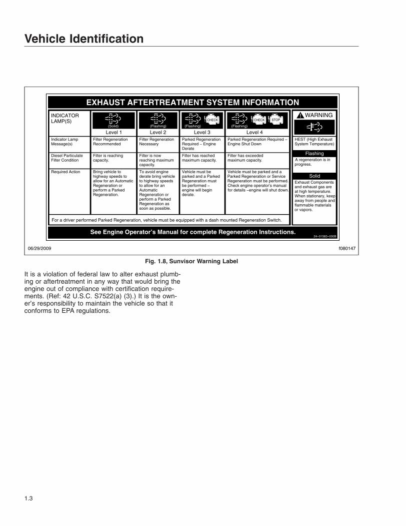
It is a violation of federal law to alter exhaust plumb-ing or aftertreatment in any way that would bring theengine out of compliance with certification require-ments. (Ref: 42 U.S.C. S7522(a) (3).) It is the own-er’s responsibility to maintain the vehicle so that itconforms to EPA regulations.
f080147
EXHAUST AFTERTREATMENT SYSTEM INFORMATION
Switch.
Level 1 Level 3Level 2 Level 4Filter RegenerationRecommended
Filter is reaching
Bring vehicle tohighway speeds to
Filter RegenerationNecessary
Filter is nowreaching maximumcapacity.
To avoid enginederate bring vehicle
Parked RegenerationRequired − EngineDerate
Filter has reachedmaximum capacity.
Vehicle must beparked and a Parked
Parked Regeneration Required −Engine Shut Down
Filter has exceededmaximum capacity
Vehicle must be parked and aParked Regeneration or Service
(Solid) (Flashing) (Flashing)
CHECK CHECK
(Flashing)
INDICATORLAMP(S)
Indicator LampMessage(s)
Diesel ParticulateFilter Condition
Required Action
capacity. .
STOP
See Engine Operator’s Manual for complete Regeneration Instructions.
allow for an AutomaticRegeneration orperform a ParkedRegeneration.
to highway speedsto allow for anAutomaticRegeneration orperform a ParkedRegeneration assoon as possible.
Regeneration mustbe performed −engine will beginderate.
Regeneration must be performed.Check engine operator’s manualfor details −engine will shut down.
For a driver performed Parked Regeneration, vehicle must be equipped with a dash mounted Regeneration Switch.
06/29/2009
24−01583−000B
WARNING
HEST (High ExhaustSystem Temperature)
Exhaust Componentsand exhaust gas areat high temperature. When stationary, keepaway from people andflammable materialsor vapors.
A regeneration is inprogress.
Flashing
Solid
Fig. 1.8, Sunvisor Warning Label
Vehicle Identification
1.3

2
Instruments and ControlsIdentification
Instrumentation Control Units . . . . . . . . . . . . . . . . . . . . . . . . . . . . . . . . . . . . . . . . . . . . . . . . . . . . . . . 2.1Warning and Indicator Lights . . . . . . . . . . . . . . . . . . . . . . . . . . . . . . . . . . . . . . . . . . . . . . . . . . . . . . . . 2.2Driver Message Center . . . . . . . . . . . . . . . . . . . . . . . . . . . . . . . . . . . . . . . . . . . . . . . . . . . . . . . . . . . . 2.5Instruments . . . . . . . . . . . . . . . . . . . . . . . . . . . . . . . . . . . . . . . . . . . . . . . . . . . . . . . . . . . . . . . . . . . . . 2.14Controls . . . . . . . . . . . . . . . . . . . . . . . . . . . . . . . . . . . . . . . . . . . . . . . . . . . . . . . . . . . . . . . . . . . . . . . . 2.18Roll Stability Advisor and Control System . . . . . . . . . . . . . . . . . . . . . . . . . . . . . . . . . . . . . . . . . . . . . 2.26Voltage and Fuel Efficiency Controls . . . . . . . . . . . . . . . . . . . . . . . . . . . . . . . . . . . . . . . . . . . . . . . . . 2.28Meritor WABCO® Antilock Braking System . . . . . . . . . . . . . . . . . . . . . . . . . . . . . . . . . . . . . . . . . . . 2.30VORAD VS-400 System . . . . . . . . . . . . . . . . . . . . . . . . . . . . . . . . . . . . . . . . . . . . . . . . . . . . . . . . . . 2.32Lane Departure Warning Controls . . . . . . . . . . . . . . . . . . . . . . . . . . . . . . . . . . . . . . . . . . . . . . . . . . . 2.38
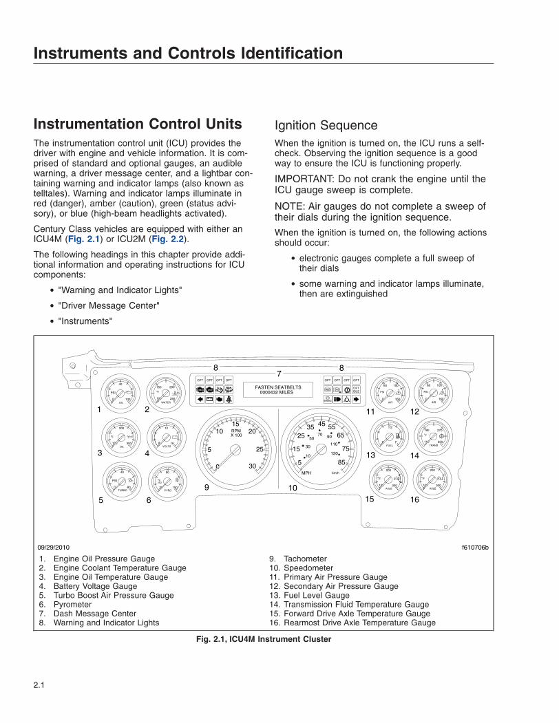
Instrumentation Control UnitsThe instrumentation control unit (ICU) provides thedriver with engine and vehicle information. It is com-prised of standard and optional gauges, an audiblewarning, a driver message center, and a lightbar con-taining warning and indicator lamps (also known astelltales). Warning and indicator lamps illuminate inred (danger), amber (caution), green (status advi-sory), or blue (high-beam headlights activated).
Century Class vehicles are equipped with either anICU4M (Fig. 2.1) or ICU2M (Fig. 2.2).
The following headings in this chapter provide addi-tional information and operating instructions for ICUcomponents:
• "Warning and Indicator Lights"
• "Driver Message Center"
• "Instruments"
Ignition SequenceWhen the ignition is turned on, the ICU runs a self-check. Observing the ignition sequence is a goodway to ensure the ICU is functioning properly.
IMPORTANT: Do not crank the engine until theICU gauge sweep is complete.
NOTE: Air gauges do not complete a sweep oftheir dials during the ignition sequence.
When the ignition is turned on, the following actionsshould occur:
• electronic gauges complete a full sweep oftheir dials
• some warning and indicator lamps illuminate,then are extinguished
0 160
10060
PSI
AIR
S
0 160
10060
PSI
AIR
P
110 350
270190
F
TRANS
100 250
200150
F
WATER
E F
1/2
FUEL
100 300
200
AXLE
F
100 300
200
AXLE
F
8 16
12
VOLTS
0 80
40
TURBO
PSI
30 150
90
PYRO
100 300
200
OIL
0 100
40
OIL
PSI
10F
F
75
6555
5
15
2535 45
8510
30
5070 90
110
130
km/hMPH
RPMX 100
1520
25
10
5
0 30
09/29/2010 f610706b
1 2
3 4
5 6
9 10
11 12
13 14
15 16
8 87
FASTEN SEATBELTS 0000432 MILES
ABS
BRAKE!
ABSSTOPCHECK
OPT OPT OPT OPTOPT OPT OPT OPT
OPTIDLE
1. Engine Oil Pressure Gauge2. Engine Coolant Temperature Gauge3. Engine Oil Temperature Gauge4. Battery Voltage Gauge5. Turbo Boost Air Pressure Gauge6. Pyrometer7. Dash Message Center8. Warning and Indicator Lights
9. Tachometer10. Speedometer11. Primary Air Pressure Gauge12. Secondary Air Pressure Gauge13. Fuel Level Gauge14. Transmission Fluid Temperature Gauge15. Forward Drive Axle Temperature Gauge16. Rearmost Drive Axle Temperature Gauge
Fig. 2.1, ICU4M Instrument Cluster
Instruments and Controls Identification
2.1

• audible alert sounds until sufficient air pressurebuilds up in the primary and secondary air sys-tems
• software revision level of the ICU is displayedon the driver message center, followed by anyactive faults
IMPORTANT: If any red or amber warning orindicator lamps do not illuminate during the ICUself-check or do not extinguish after the self-check completes, take the action outlined inTable 2.1, or take the vehicle to an authorizedDaimler Trucks service facility as soon as pos-sible.
NOTE: If active faults are present, take the ve-hicle to an authorized Daimler Trucks servicefacility as soon as possible.
If the ICU receives active fault codes, it displaysthem one after the other until the parking brake isreleased or the ignition is turned off. Once the park-ing brake is completely released, the ICU displaysthe odometer. If there are no active faults, the ICUdisplays the odometer after the self-check completes.
When the self-check is complete on an ICU4M, thefasten seat belt screen displays if the engine is off. Ifthe engine is running, the idle hours screen displays.
Audible AlertsAn audible alert sounds during the ignition sequenceand whenever one of the following conditions exists:
• Engine oil pressure falls below the minimumpreset value.
• Coolant temperature rises above the maximumpreset value.
• Air pressure falls below approximately 70 psi(483 kPa).
• Parking brake is set with the vehicle movingfaster than two miles per hour.
• System voltage falls below 12 volts.
• Door is open or the headlights are on, with theparking brake off.
Warning and Indicator LightsThe ICU lightbar has three or four rows of warningand indicator lights with icon symbols, depending onthe ICU. The positions of the lights may vary for thedifferent ICU’s, but the telltales are standard for allapplications. See Table 2.1 for a listing of standardand commonly used warning and indicator lamps.
Warning and indicator lamps illuminate in red (dan-ger), amber (caution), green (status advisory), orblue (high-beam headlights active).
IMPORTANT: Depending upon local jurisdic-tional emissions guidelines, vehicles may not beequipped with all of the lamps shown inTable 2.1.
Engine Protection System
WARNINGWhen the red STOP engine lamp illuminates,most engines are programmed to shut down au-tomatically within 30 seconds. The driver mustimmediately move the vehicle to a safe locationat the side of the road to prevent causing a haz-ardous situation that could cause bodily injury,property damage, or severe damage to the en-gine.
See Fig. 2.3 for an explanation of the aftertreatmentsystem (ATS) warning indicators, and actions re-quired to avoid further engine protection steps.
f60099109/27/95
1
2 34
1. Main Dash Panel2. Lightbar3. Driver Message Center4. Warning and Indicator Lights
Fig. 2.2, ICU2M Instrument Cluster
Instruments and Controls Identification
2.2
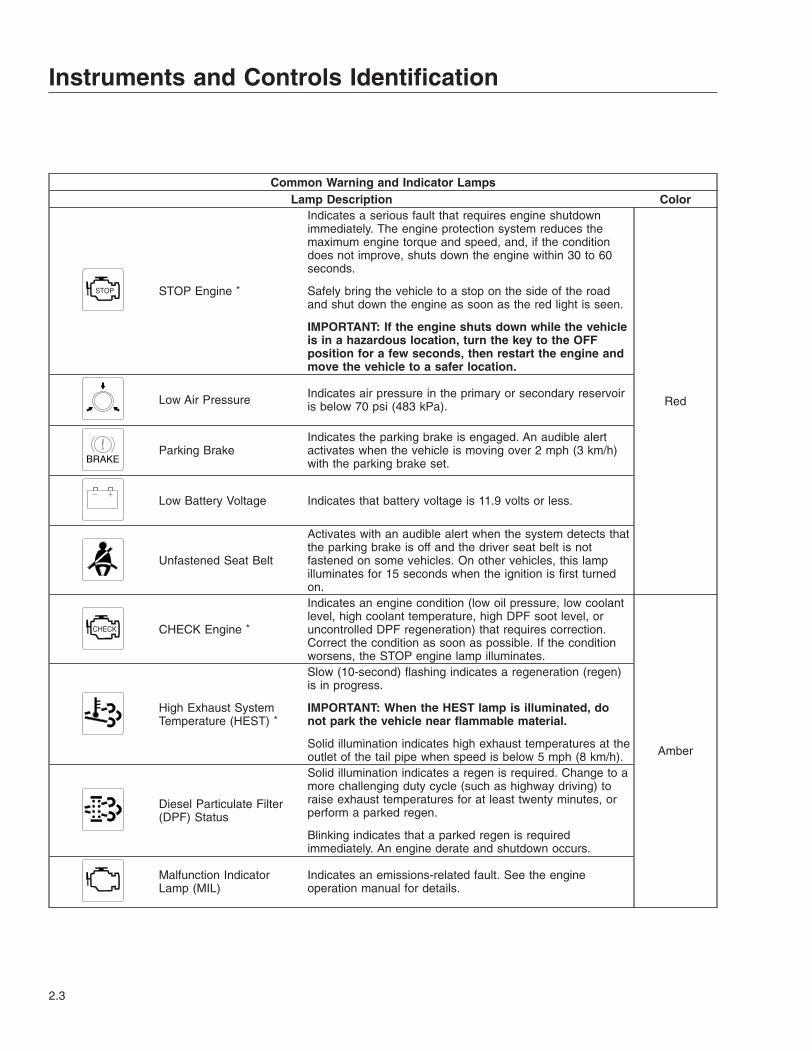
Common Warning and Indicator LampsLamp Description Color
STOP STOP Engine *
Indicates a serious fault that requires engine shutdownimmediately. The engine protection system reduces themaximum engine torque and speed, and, if the conditiondoes not improve, shuts down the engine within 30 to 60seconds.
Safely bring the vehicle to a stop on the side of the roadand shut down the engine as soon as the red light is seen.
IMPORTANT: If the engine shuts down while the vehicleis in a hazardous location, turn the key to the OFFposition for a few seconds, then restart the engine andmove the vehicle to a safer location.
RedLow Air Pressure Indicates air pressure in the primary or secondary reservoiris below 70 psi (483 kPa).
BRAKEParking Brake
Indicates the parking brake is engaged. An audible alertactivates when the vehicle is moving over 2 mph (3 km/h)with the parking brake set.
Low Battery Voltage Indicates that battery voltage is 11.9 volts or less.
Unfastened Seat Belt
Activates with an audible alert when the system detects thatthe parking brake is off and the driver seat belt is notfastened on some vehicles. On other vehicles, this lampilluminates for 15 seconds when the ignition is first turnedon.
CHECK CHECK Engine *
Indicates an engine condition (low oil pressure, low coolantlevel, high coolant temperature, high DPF soot level, oruncontrolled DPF regeneration) that requires correction.Correct the condition as soon as possible. If the conditionworsens, the STOP engine lamp illuminates.
Amber
High Exhaust SystemTemperature (HEST) *
Slow (10-second) flashing indicates a regeneration (regen)is in progress.
IMPORTANT: When the HEST lamp is illuminated, donot park the vehicle near flammable material.
Solid illumination indicates high exhaust temperatures at theoutlet of the tail pipe when speed is below 5 mph (8 km/h).
Diesel Particulate Filter(DPF) Status
Solid illumination indicates a regen is required. Change to amore challenging duty cycle (such as highway driving) toraise exhaust temperatures for at least twenty minutes, orperform a parked regen.
Blinking indicates that a parked regen is requiredimmediately. An engine derate and shutdown occurs.
Malfunction IndicatorLamp (MIL)
Indicates an emissions-related fault. See the engineoperation manual for details.
Instruments and Controls Identification
2.3
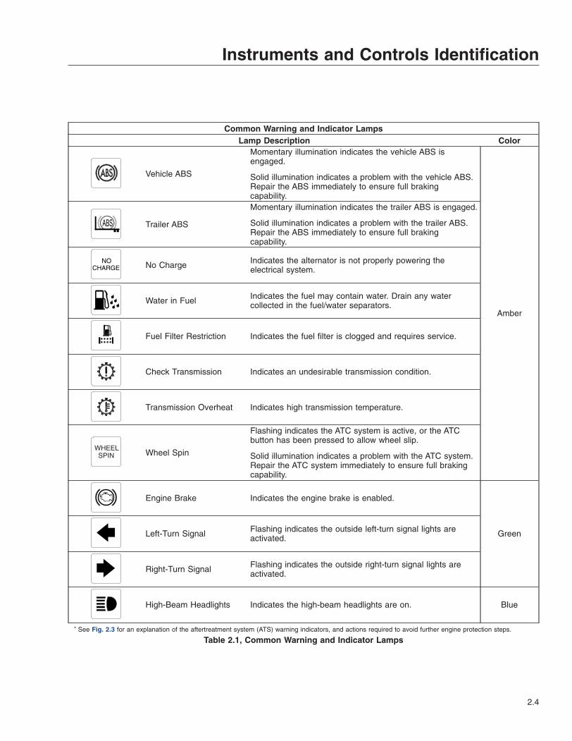
Common Warning and Indicator LampsLamp Description Color
Vehicle ABS
Momentary illumination indicates the vehicle ABS isengaged.
Solid illumination indicates a problem with the vehicle ABS.Repair the ABS immediately to ensure full brakingcapability.
Amber
Trailer ABS
Momentary illumination indicates the trailer ABS is engaged.
Solid illumination indicates a problem with the trailer ABS.Repair the ABS immediately to ensure full brakingcapability.
NOCHARGE No Charge Indicates the alternator is not properly powering the
electrical system.
Water in Fuel Indicates the fuel may contain water. Drain any watercollected in the fuel/water separators.
Fuel Filter Restriction Indicates the fuel filter is clogged and requires service.
Check Transmission Indicates an undesirable transmission condition.
Transmission Overheat Indicates high transmission temperature.
WHEELSPIN Wheel Spin
Flashing indicates the ATC system is active, or the ATCbutton has been pressed to allow wheel slip.
Solid illumination indicates a problem with the ATC system.Repair the ATC system immediately to ensure full brakingcapability.
Engine Brake Indicates the engine brake is enabled.
GreenLeft-Turn Signal Flashing indicates the outside left-turn signal lights areactivated.
Right-Turn Signal Flashing indicates the outside right-turn signal lights areactivated.
High-Beam Headlights Indicates the high-beam headlights are on. Blue
* See Fig. 2.3 for an explanation of the aftertreatment system (ATS) warning indicators, and actions required to avoid further engine protection steps.
Table 2.1, Common Warning and Indicator Lamps
Instruments and Controls Identification
2.4
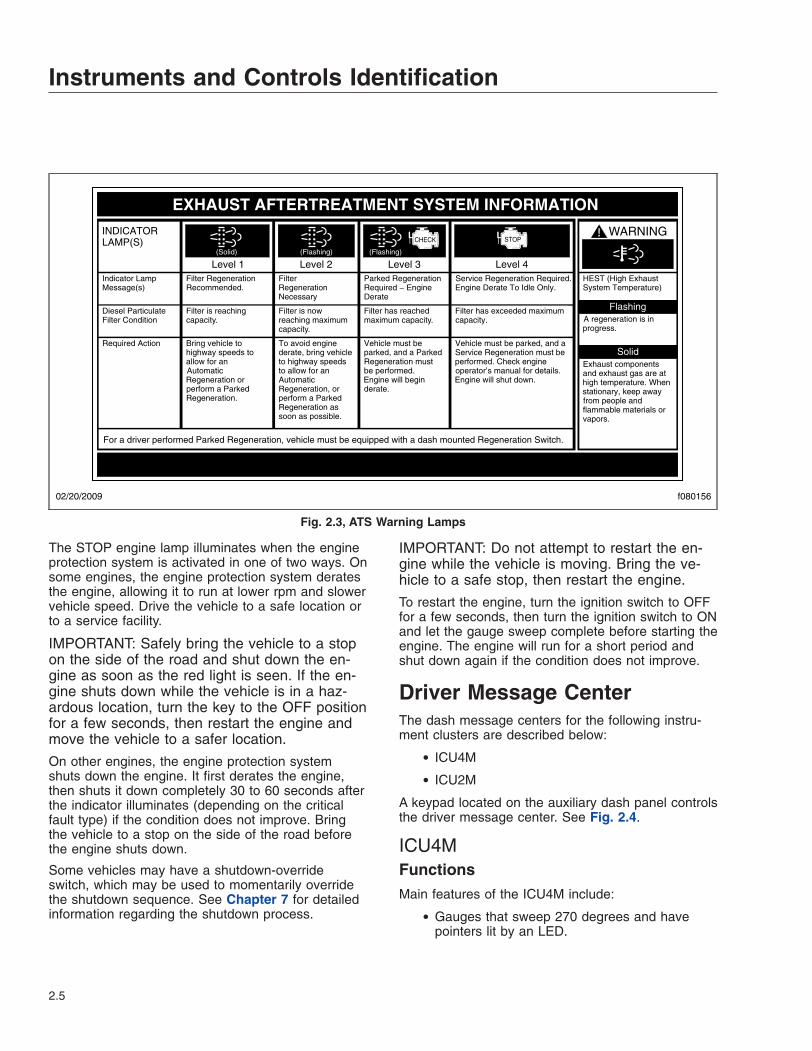
The STOP engine lamp illuminates when the engineprotection system is activated in one of two ways. Onsome engines, the engine protection system deratesthe engine, allowing it to run at lower rpm and slowervehicle speed. Drive the vehicle to a safe location orto a service facility.
IMPORTANT: Safely bring the vehicle to a stopon the side of the road and shut down the en-gine as soon as the red light is seen. If the en-gine shuts down while the vehicle is in a haz-ardous location, turn the key to the OFF positionfor a few seconds, then restart the engine andmove the vehicle to a safer location.
On other engines, the engine protection systemshuts down the engine. It first derates the engine,then shuts it down completely 30 to 60 seconds afterthe indicator illuminates (depending on the criticalfault type) if the condition does not improve. Bringthe vehicle to a stop on the side of the road beforethe engine shuts down.
Some vehicles may have a shutdown-overrideswitch, which may be used to momentarily overridethe shutdown sequence. See Chapter 7 for detailedinformation regarding the shutdown process.
IMPORTANT: Do not attempt to restart the en-gine while the vehicle is moving. Bring the ve-hicle to a safe stop, then restart the engine.
To restart the engine, turn the ignition switch to OFFfor a few seconds, then turn the ignition switch to ONand let the gauge sweep complete before starting theengine. The engine will run for a short period andshut down again if the condition does not improve.
Driver Message CenterThe dash message centers for the following instru-ment clusters are described below:
• ICU4M
• ICU2M
A keypad located on the auxiliary dash panel controlsthe driver message center. See Fig. 2.4.
ICU4MFunctionsMain features of the ICU4M include:
• Gauges that sweep 270 degrees and havepointers lit by an LED.
f080156
EXHAUST AFTERTREATMENT SYSTEM INFORMATION
Switch.
Level 1 Level 3Level 2 Level 4Filter RegenerationRecommended.
Filter is reaching
Bring vehicle tohighway speeds to
Filter Regeneration
Filter is nowreaching maximumcapacity.
To avoid enginederate, bring vehicle
Parked RegenerationRequired − EngineDerate
Filter has reachedmaximum capacity.
Vehicle must beparked, and a Parked
Service Regeneration Required.Engine Derate To Idle Only.
Filter has exceeded maximumcapacity.
Vehicle must be parked, and aService Regeneration must be
(Solid) (Flashing) (Flashing)
CHECKINDICATORLAMP(S)
Indicator LampMessage(s)
Diesel ParticulateFilter Condition
Required Action
capacity.
STOP
allow for an AutomaticRegeneration orperform a Parked
to highway speedsto allow for anAutomaticRegeneration, orperform a ParkedRegeneration assoon as possible.
Regeneration mustbe performed.Engine will beginderate.
performed. Check engineoperator’s manual for details.Engine will shut down.
For a driver performed Parked Regeneration, vehicle must be equipped with a dash mounted Regeneration Switch.
02/20/2009
WARNING
HEST (High ExhaustSystem Temperature)
Exhaust componentsand exhaust gas are athigh temperature. Whenstationary, keep awayfrom people andflammable materials orvapors.
A regeneration is inprogress.
Flashing
Solid
Regeneration.
Necessary
Fig. 2.3, ATS Warning Lamps
Instruments and Controls Identification
2.5
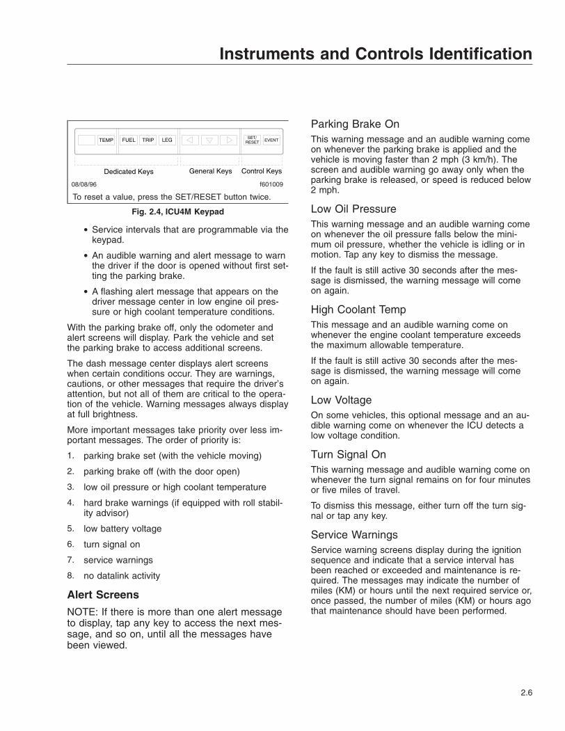
• Service intervals that are programmable via thekeypad.
• An audible warning and alert message to warnthe driver if the door is opened without first set-ting the parking brake.
• A flashing alert message that appears on thedriver message center in low engine oil pres-sure or high coolant temperature conditions.
With the parking brake off, only the odometer andalert screens will display. Park the vehicle and setthe parking brake to access additional screens.
The dash message center displays alert screenswhen certain conditions occur. They are warnings,cautions, or other messages that require the driver’sattention, but not all of them are critical to the opera-tion of the vehicle. Warning messages always displayat full brightness.
More important messages take priority over less im-portant messages. The order of priority is:
1. parking brake set (with the vehicle moving)
2. parking brake off (with the door open)
3. low oil pressure or high coolant temperature
4. hard brake warnings (if equipped with roll stabil-ity advisor)
5. low battery voltage
6. turn signal on
7. service warnings
8. no datalink activity
Alert Screens
NOTE: If there is more than one alert messageto display, tap any key to access the next mes-sage, and so on, until all the messages havebeen viewed.
Parking Brake OnThis warning message and an audible warning comeon whenever the parking brake is applied and thevehicle is moving faster than 2 mph (3 km/h). Thescreen and audible warning go away only when theparking brake is released, or speed is reduced below2 mph.
Low Oil PressureThis warning message and an audible warning comeon whenever the oil pressure falls below the mini-mum oil pressure, whether the vehicle is idling or inmotion. Tap any key to dismiss the message.
If the fault is still active 30 seconds after the mes-sage is dismissed, the warning message will comeon again.
High Coolant TempThis message and an audible warning come onwhenever the engine coolant temperature exceedsthe maximum allowable temperature.
If the fault is still active 30 seconds after the mes-sage is dismissed, the warning message will comeon again.
Low VoltageOn some vehicles, this optional message and an au-dible warning come on whenever the ICU detects alow voltage condition.
Turn Signal OnThis warning message and audible warning come onwhenever the turn signal remains on for four minutesor five miles of travel.
To dismiss this message, either turn off the turn sig-nal or tap any key.
Service WarningsService warning screens display during the ignitionsequence and indicate that a service interval hasbeen reached or exceeded and maintenance is re-quired. The messages may indicate the number ofmiles (KM) or hours until the next required service or,once passed, the number of miles (KM) or hours agothat maintenance should have been performed.
08/08/96 f601009
Dedicated Keys General Keys Control Keys
To reset a value, press the SET/RESET button twice.
Fig. 2.4, ICU4M Keypad
Instruments and Controls Identification
2.6

Automated Transmission DisplayThe ICU4M can display current gear information forvehicles with an automated transmission. The lastthree digits at the far right on the lower line of thedriver display screen are reserved for this informa-tion.
If there is a request to shift, an up or down arrow isalso displayed, depending on the shift direction.
On vehicles with conventional manual or automatictransmissions, the gear and shift direction are notdisplayed. For more information about specificmodels of automated transmissions, see Chapter 8.
Mobile ScreensThe following screens are available when the parkingbrake is off (when the vehicle is mobile).
i. Fasten seat belt (rpm<100)
ii. Fuel economy (rpm>100)
iii. Odometer
iv. Trip distance/hours
v. Trip advisory
vi. Leg distance/hours
vii. Leg advisory
viii. Outside air temperature
ix. Fuel used/average MPG (KM/L)
Stationary Screens
NOTE: Metric unit screens are similar. AMT=Current gear information for automated manualtransmissions.
The following screens are available when the parkingbrake is on (when the vehicle is stationary).
i. Odometer
ii. Trip information including trip miles/hours, idlehours, average speed, leg miles/hours
iii. Fuel information including fuel used, fueleconomy, idle/PTO fuel usage
iv. Engine information including engine miles/hours,engine/PTO gallons, oil level
v. Diagnostic information
vi. Service information including mileage or time tonext service
vii. Setup information
viii. Vehicle information including Datalink status, ICUserial number, software version
ix. Fasten seat belt warning
Trip InformationWhen idle hours are displayed, tap the any key toaccess the main trip information screen. SeeFig. 2.5. Tap the arrow keys on the 10-key keypad to
Engine Idling
IDLE HOURS 1234:56 12.3GAL123456.7MI AMT
FASTEN SEATBELTS 123456.7 MILES AMT
Press Right Arrow Key and Set the Parking Brake
TRIP MILES 123456.7 TRIP HR 1234:56 AMT
IDLE HOURS 1234:56 AVG MPH 12.3 AMT
LEG MILES 123456.7 LEG HR 1234:56 AMT
R R R
TRIP INFORMATION AMT
12/01/2004 f040699
(100 RPM or more)
Go to Fuel Information Screens
Fig. 2.5, ICU4M Trip Information Screens
Instruments and Controls Identification
2.7
advance through the screens. Press and hold theSET/RESET key to reset any of the screens.
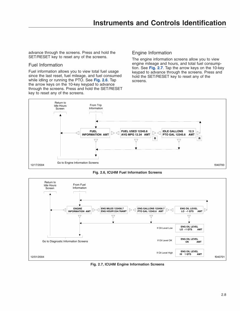
Fuel InformationFuel information allows you to view total fuel usagesince the last reset, fuel mileage, and fuel consumedwhile idling or running the PTO. See Fig. 2.6. Tapthe arrow keys on the 10-key keypad to advancethrough the screens. Press and hold the SET/RESETkey to reset any of the screens.
Engine InformationThe engine information screens allow you to viewengine mileage and hours, and total fuel consump-tion. See Fig. 2.7. Tap the arrow keys on the 10-keykeypad to advance through the screens. Press andhold the SET/RESET key to reset any of thescreens.
IDLE GALLONS 12.3 PTO GAL 12345.6 AMT
FUEL USED 12345.6 AVG MPG 12.34 AMT
R R
FUEL INFORMATION AMT
f040700Go to Engine Information Screens
12/17/2004
Return to Idle Hours From Trip
InformationScreen
Fig. 2.6, ICU4M Fuel Information Screens
ENG GALLONS 123456.7 PTO GAL 12345.6 AMT
ENG MILES 123456.7 ENG HOUR1234:78AMT
ENG OIL LEVEL LO −1 QTS AMT
ENGINE INFORMATION AMT
12/01/2004
ENG OIL LEVEL LO −1 QTS AMT
If Oil Level OK ENG OIL LEVEL
OK AMT
If Oil Level High ENG OIL LEVEL
HI 1 QTS AMT
If Oil Level Low
f040701
Go to Diagnostic Information Screens
Return to Idle Hours From Fuel
InformationScreen
Fig. 2.7, ICU4M Engine Information Screens
Instruments and Controls Identification
2.8
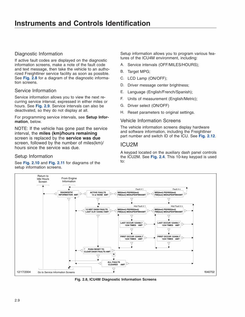
Diagnostic InformationIf active fault codes are displayed on the diagnosticinformation screens, make a note of the fault codeand text message, then take the vehicle to an autho-rized Freightliner service facility as soon as possible.See Fig. 2.8 for a diagram of the diagnostic informa-tion screens.
Service InformationService information allows you to view the next re-curring service interval, expressed in either miles orhours. See Fig. 2.9. Service intervals can also bedeactivated, so they do not display at all.
For programming service intervals, see Setup Infor-mation, below.
NOTE: If the vehicle has gone past the serviceinterval, the miles (km)/hours remainingscreen is replaced by the service was duescreen, followed by the number of miles(km)/hours since the service was due.
Setup InformationSee Fig. 2.10 and Fig. 2.11 for diagrams of thesetup information screens.
Setup information allows you to program various fea-tures of the ICU4M environment, including:
A. Service intervals (OFF/MILES/HOURS);
B. Target MPG;
C. LCD Lamp (ON/OFF);
D. Driver message center brightness;
E. Language (English/French/Spanish);
F. Units of measurement (English/Metric);
G. Driver select (ON/OFF)
H. Reset parameters to original settings.
Vehicle Information ScreensThe vehicle information screens display hardwareand software information, including the Freightlinerpart number and switch ID of the ICU. See Fig. 2.12.
ICU2MA keypad located on the auxiliary dash panel controlsthe ICU2M. See Fig. 2.4. This 10-key keypad is usedto:
MID(text) PID/SID(text) FMI(text) MID#sPID#FMI#AMT
ACTIVE FAULTS 12 or NONE AMT
12 HIST DASH FAULTS LAST CLR 123456.7AMT
LAST OCCUR 123456.7 1234 TIMES AMT
FIRST OCCUR 123456.7 1234 TIMES AMT
MID(text) PID/SID(text) FMI(text) MID#sPID#FMI#AMT
MID(text) PID/SID(text) FMI(text) MID#sPID#FMI#AMT
Fault # 1 Fault # n
Hist Fault # 1
MID(text) PID/SID(text) FMI(text) MID#sPID#FMI#AMT
Hist Fault # n
LAST OCCUR 123456.7 1234 TIMES AMT
FIRST OCCUR 123456.7 1234 TIMES AMT
2 PUSH RESET TO CLEAR DASH FAULTS AMT
R
ALL FAULTS CLEARED AMT
DIAGNOSTIC INFORMATION AMT
Go to Service Information Screens f040702
Return to Idle Hours From Engine
InformationScreen
12/17/2004
Fig. 2.8, ICU4M Diagnostic Information Screens
Instruments and Controls Identification
2.9

• call up information on mobile screens;
• navigate from screen to screen;
• set up the display;
• record significant data.
The odometer is a seven-digit display with one deci-mal point after the sixth digit, allowing it to displaytenths of miles (or kilometers). When first installed,the odometer starts at 0.0 miles (or kilometers).When replaced, the odometer starts again from 0.0.
INTERVAL IS SET TO XXXXX MILES AMT
R
OR
Distance prior to reaching the set Service Interval
Distance traveled beyond the set Service Interval
R
SERVICE WAS DUE 12345 MILES AGO AMT
Time accumulated beyond the set Service Interval
Time prior to reaching the set Service Interval
INTERVAL IS SET TO XXXX HOURS AMT
SERVICE INFORMATION AMT
SERVICE INFORMATION AMT
12345 MILES TO NEXT SERVICE AMT
1234 HOURS TO NEXT SERVICE AMT
SERVICE WAS DUE 1234 HOURS AGO AMT
R
OR R
f040703Go to Setup Information Screens
Go to Set−up Information Screens
Return to Idle Hours From Diagnostic
InformationScreen
12/17/2004
NOTE: Service information screens only appear if the service interval is set to MILES or HOURS in Setup Information.
Fig. 2.9, ICU4M Service Information Screens
SETUP INFORMATION AMT
PUSH SET KEY TO CHANGE SERVICE AMT
OR
S INTERVAL XXXXX MILES <−−LESS MORE−−> AMT
If Service Interval is set to MILES
SERVICE INTERVAL OFF/ MILES /HOURS AMT
S
PUSH SET KEY TO CHANGE SERVICE MI AMT
PUSH SET KEY TO CHANGE SERVICE HR AMT
S SERVICE INTERVAL
OFF/ MILES / HOURS AMT
If Service Interval is set to HOURS
INTERVAL XXXX HOURS <−−LESS MORE−−> AMT
S
To more Setup Information
Go to Vehicle Information Screens
f040704
Return to Idle Hours From Service
InformationScreen
12/17/2004
Fig. 2.10, ICU4M Setup Information Screens (for service intervals)
Instruments and Controls Identification
2.10

Alert ScreensAlert screens can appear at any time, even when thevehicle is moving. They override the regular screendisplay. They are warnings, cautions, or other mes-sages that require the driver’s attention, but not all ofthem are critical to the operation of the vehicle. Theword Warning or Alert sometimes flashes on thedisplay screen above the alert text. More importantmessages take priority over less important mes-sages.
NOTE: If there is more than one alert messageto display, press any button to scroll to the nextmessage, and so on until all the messages havebeen viewed.
Parking Brake OnThis warning message and an audible warning comeon whenever the parking brake is applied and thevehicle is moving faster than 2 mph (3 km/h). Thescreen and audible warning go away only when theparking brake is released, or speed is reduced below2 mph (3 km/h).
Low Oil Pressure
NOTE: All alert screens follow Low Oil Pressurealert format.
This warning message and an audible warning comeon whenever the oil pressure falls below the mini-mum oil pressure, whether the vehicle is idling or inmotion. See Fig. 2.13. To dismiss the message,press any button on the keypad.
If low oil pressure is detected during the ignition se-quence, it displays as an active fault and the alertscreen does not appear. After 30 seconds, this mes-sage displays again.
Low Coolant LevelThis warning message and audible warning activatewhenever the coolant level falls below a preset point.
PUSH SET KEY TO CHANGE TARGET MPG AMT
TARGET MPG: <−−LESS MORE−−>AMT
S LCD LAMP
<−−OFF ON −−> AMT
S DISPLAY BRIGHTNESS <−−DARK LIGHT−−>AMT
S
S
PUSH SET KEY TO CHANGE LCD LAMP AMT
PUSH SET KEY TO CHANGE BRIGHTNESS AMT
PUSH SET KEY TO CHANGE LANGUAGE AMT
PUSH SET KEY TO CHANGE UNITS AMT
PUSH SET KEY TO CHANGE PARAMETERS AMT S RESET PARAMETERS
<−− NO−−> AMT
UNITS / METRIC AMT
LANGUAGE: FRENCH/SPANISH AMT
f040705Go to Vehicle Information Screens
Go to Setup Information Screens
12/17/2004
ENGLISH
ENGLISH
12.3S
YES
Fig. 2.11, Other Setup Information
VEHICLE INFORMATION AMT
DATALINK ACTIVE AMT
DATA LINK STATUS USAGE 12% ERR1%AMT
DASH# XXX−XXXXX−XXX SW# P1.2.3 AMT
f040706
Return to Trip Information Screens
01/11/2005
From SetupInformation
Return to Idle Hours
Screen
Fig. 2.12, ICU4M Vehicle Information Screens
Instruments and Controls Identification
2.11

High Coolant TempThis message and an audible warning come onwhenever the engine coolant temperature exceedsthe maximum allowable temperature.
If high coolant temperature is detected during theignition sequence, it displays as an active fault andthe alert screen does not appear. After 30 seconds,this message displays again.
Low VoltageOn some vehicles, this optional message and an au-dible warning come on whenever the ICU detects alow voltage condition.
Faulty Speedo GaugeThis message is displayed when the system detectsa faulty speedometer. This becomes the defaultscreen, and vehicle speed is displayed as a digitalreadout at the bottom left of the screen. All otherscreens and functions operate normally.
Recirc Mode Engaged/Provide Fresh AirThe Recirc Mode Engaged message appears when-ever recirculated air is selected on the fresh/air recir-culation switch or the air circulation switch is rotatedto the maximum air conditioning position. It displaysone time only for seven seconds. It notifies the driverthat recirculated air is being used and that fresh airneeds to be provided after 20 minutes.
If fresh air is not provided after 20 minutes, ProvideFresh Air is displayed. It displays for seven secondsapproximately every four minutes until the driver se-lects fresh air on the fresh/air recirculation switch orrotates the air circulation switch away from maximumair conditioning. See Chapter 4 for detailed operatinginstructions for the heater/air conditioner.
Low Fuel LevelThe ICU continuously monitors fuel level. When thefuel level drops to 1/8th full, the word Warningflashes on the message display screen above thelow fuel alert.
Turn Signal OnThis message (the audible warning is optional) ap-pears whenever the turn signal remains on beyond apreset time or distance traveled.
To dismiss this message, either turn off the turn sig-nal or press any button on the keypad.
Service WarningsService warning screens display during the ignitionsequence and indicate that a service interval hasbeen reached or exceeded and maintenance is re-quired. The messages may indicate the number ofmiles (KM) or hours until the next required service or,once passed, the number of miles (KM) or hours agothat maintenance should have been performed. TheICU2M can be programmed using ServiceLink togenerate service warnings in either miles or hours,but not both.
No Datalink ActivityThis message appears whenever the datalink is notreceiving data. If the condition persists, take the ve-hicle in for service as soon as possible to discoverthe cause of the problem.
Mobile ScreensThe following screens are available when the parkingbrake is off (when the vehicle is mobile) and no ac-tive fault codes are found. Press the appropriate but-ton on the keypad to display one of the mobilescreens.
• trip miles and hours
• fuel used and average MPG
• leg miles and hours
08/17/95 f040307
WARNINGLOW OIL PRESSURE
RETURN TONORMAL
NORMAL OPERATIONSCREEN
PRESS ANY KEY
INITIALWARNING
BLINKINGWARNING
OPERATION
NOTE: All Alert Screens follow this format.
Fig. 2.13, ICU2M Alert Screen: Low Oil Pressure
Instruments and Controls Identification
2.12

NOTE: Resetting trip miles and hours also re-sets leg miles and hours.
To reset a mobile screen, push the Set/Reset buttontwice within a 6-second period while the screen isdisplayed. A confirmation screen will display after youpress the button once.
NOTE: If the memory in the data logger is full,the screen will display Memory Full Data NotRecorded. If the data logger is not connectedor not responding, the screen will display DataRecorder Not Responding. If the EVENT but-ton was pressed within the last two minutes, thescreen will display Still Recording Last Event.
Stationary ScreensThe following screens are available when the parkingbrake is applied (vehicle is stationary) and no activefault codes are found. Each set of stationary screenshas a title screen followed by one or more datascreens.
To move forward and backward through thesescreens, use the three arrow buttons on the keypad.See Fig. 2.14, Fig. 2.15, and Fig. 2.16 for stationaryscreen navigation.
i. Trip Information: miles, hours
ii. Fuel information: fuel used, average MPG
iii. Engine information: engine miles and hours, en-gine gallons and PTO gallons
iv. Diagnostic information: active faults, historicaldash faults
v. Setup Information: target MPG, brightness, lan-guage, units of measurement
vi. Vehicle information: datalink activity/status, ICUpart number, software ID number
ENG GALLONS 123456.7PTO GALLONS 123456.7
ENG MILES 1234567.8ENG HOURS 123456:78
ENGINEINFORMATION
IDLE HOURS 1234.5612.3 GAL 1234567 MI
IGNITIONON ONLY
FASTEN SEATBELTS1234567 MILES
IDLING
f04032502/13/96
FIRST SECOND LAST
See applicable Figure.
LASTFIRST PUSH RESET TOCLEAR DASH FAULTS
123 HIST DASH FAULTSLAST CLEAR 1234567
ACTIVE FAULTS1234 or NONE
For each fault, display fault codes and description.
For each fault, display fault codes and description.
R =RESET (PUSH RESET/SET KEY TWICE)
=SET (PUSH RESET/SET KEY ONCE)S
R
See applicable Figure for trip and fuel information.
LAST OCCR
FIRST OCCR
LAST OCCR
FIRST OCCR
DIAGNOSTICINFORMATION
Fig. 2.14, ICU2M Engine Information and Diagnostic Information
Instruments and Controls Identification
2.13

InstrumentsStandard instruments are present on every vehicle.Optional instruments, typically located on the auxil-iary dash panel or right-hand control panel, are notfound on every vehicle. Instruments are listed here inalphabetical order to make the information easier tofind.
Air Intake Restriction GaugeThe air intake restriction gauge indicates the vacuumon the engine side of the air cleaner. On standardinstallations, it is mounted on the air cleaner. As anoption for easier viewing, an air intake restriction indi-cator (see Fig. 2.17) can be mounted on the auxiliarydash panel.
NOTE: Rain or snow can wet the filter elementand cause a temporary high reading.
Air intake restriction vacuum is measured in inchesof water (inH 2O). For vehicles equipped with agraduated indicator or a restriction gauge on the
dash, check the gauge with the engine off. If the yel-low signal stays locked in the red zone once the en-gine is shut down, or is at or above the valuesshown in Table 2.2, the air cleaner element needs tobe replaced.
Air Intake Maximum Restriction Values: (inH 2O)
Engine Make Pre-EPA07Engines EPA07 Engines
Caterpillar 25 —Cummins 25 25Detroit™ 20 22Mercedes-Benz 22 22
Table 2.2, Air Intake Maximum Restriction Values
Vehicles may be equipped with a go/no-go restrictionindicator without graduations (see Fig. 2.18) insteadof a graduated indicator.
If air restriction exceeds the maximum allowablevalue, operate the vehicle for one more day, makingsure not to run the engine over rated rpm. Refer to
R =RESET (PUSH RESET/SET KEY TWICE)
=SET (PUSH RESET/SET KEY ONCE)S01/29/98 f040326a
To trip informationSee applicable Figure.
VEHICLEINFORMATION
S
S
S
S
PUSH SET KEY TOCHANGE LANGUAGE
LANGUAGE ENGLISHFRENCH SPANISH
UNITSENGLISH METRIC
PUSH SET KEY TOCHANGE UNITS
SETUPINFORMATION
DATA LINK ACTIVE DATA LINK STATUSUSAGE 40% ERROR 6%
DASH #SW#
A06−XXXXX−XXX7.3.9
CURRENT UNITSIS FLASHING
CURRENT LANGUAGEIS FLASHING
S
SPUSH SET KEY TOCHANGE BRIGHTNESS
S
SPUSH SET KEY TOCHANGE TARGET MPG
TARGET MPG 7.0
DISPLAY BRIGHTNESS
<−−LESS MORE−−>
<−−LIGHT DARK−−>
SeeapplicableFigure.
Fig. 2.15, ICU2M Setup Information and Vehicle Information
Instruments and Controls Identification
2.14

the engine operation manual for more information onrated rpm for your engine.
If air restriction exceeds the maximum value again,replace the air cleaner element. For instructions,refer to Group 09 of the Century Class Trucks Work-shop Manual.
IDLE HOURS 1234:56AVERAGE MPH 12.3
LEG MILES 123456.7LEG HOURS 1234:56
TRIP MILES 123456.7TRIP HOURS 1234:56
IDLE GALLONS 12345.6PTO GALLONS 12345.6
FUEL USED 12345.6AVERAGE MPG 12.34
FUELINFORMATION
ENG MILES 1234567.8ENG HOURS 123456:78
ENGINEINFORMATION
IDLE HOURS 1234:5612.3 GAL 1234567 MI
IGNITIONON ONLY
FASTEN SEATBELTS1234567 MILES
f040324a01/28/98
TRIPINFORMATION
IDLING
ENG GALLONS 123456.7PTO GALLONS 123456.7
See applicable figure
R =RESET (PUSH RESET/SET KEY TWICE)
=SET (PUSH RESET/SET KEY ONCE)S
R R
R R R
Fig. 2.16, ICU2M Trip Information, Fuel Information, and Engine Information
10/10/2001 f610568
Fig. 2.17, Air Intake Restriction Indicator
04/08/2005 f090431
Fig. 2.18, Manual-Reset Air Restriction Indicator, Go/No-Go
Instruments and Controls Identification
2.15

AmmeterAn ammeter measures current flowing to and fromthe battery. When the batteries are charging, themeter needle moves to the plus side of the gauge;when the batteries are being discharged, the needlemoves to the minus side. A consistent negative read-ing when the engine is running indicates a possibleproblem with the charging system.
Application Air Pressure GaugeAn application air pressure gauge registers the airpressure being used to apply the brakes, and shouldbe used for reference only. The gauge will not regis-ter air pressure until the foot brake pedal is de-pressed or the trailer hand brake is applied.
Coolant Temperature Gauge
NOTICEA sudden increase in coolant temperature mayindicate engine or cooling system failure. Bringthe vehicle to a safe stop and investigate thecause to prevent further damage. Do not operatethe engine until the cause has been determinedand corrected.
During normal engine operation, the coolant tem-perature gauge should read between 175 and 195°F(79 and 91°C). If the temperature remains below160°F (71°C), inspect the cooling system to deter-mine the cause.
If the temperature exceeds the maximum tempera-ture shown in Table 2.3, inspect the cooling systemto determine the cause. See the Century ClassTrucks Workshop Manual for troubleshooting andrepair procedures.
Maximum Coolant TemperatureEngine Make Temperature: °F (°C)
Caterpillar 215 (101)Cummins 225 (107)Detroit 215 (101)Mercedes-Benz 221 (105)
Table 2.3, Maximum Coolant Temperature
If coolant temperature rises above the maximumtemperature listed in Table 2.3 on EPA07 engines,the CHECK engine lamp will illuminate. If the condi-
tion does not improve, the STOP engine lamp willalso illuminate and an audible warning will sound.The engine will then derate or shut down, dependingon the type of engine protection system installed.
Drive Axle Oil Temperature Gauges
NOTICEA sudden increase in oil temperature that is notcaused by a load increase may indicate mechani-cal failure. Bring the vehicle to a safe stop andinvestigate the cause to prevent further damage.Do not operate the vehicle until the cause hasbeen determined and corrected.
During normal operation, drive axle oil temperaturegauges should read as follows:
• 160 to 220°F (71 to 104°C) for Detroit™ andMeritor™ drive axles
• 180 to 200°F (82 to 93°C) for Dana Spicer®drive axles
Under heavy loads, such as when climbing steepgrades, temperatures that exceed the normal oil tem-perature range for a short period are not unusual. Ifthe temperature returns to normal when the load de-creases, there is no problem.
Engine Oil Pressure Gauge
NOTICEA sudden decrease or absence of oil pressuremay indicate mechanical failure. Bring the vehicleto a safe stop and investigate the cause to pre-vent further damage. Do not operate the engineuntil the cause has been determined and cor-rected.
The engine oil pressure gauge displays the currentengine oil pressure. If engine oil pressure falls belowthe minimum levels shown in Table 2.4, the CHECKengine lamp will illuminate. If the condition does notimprove, the STOP engine lamp will also illuminateand an audible warning will sound. The engine willthen derate or shut down, depending on the type ofengine protection system installed.
Instruments and Controls Identification
2.16
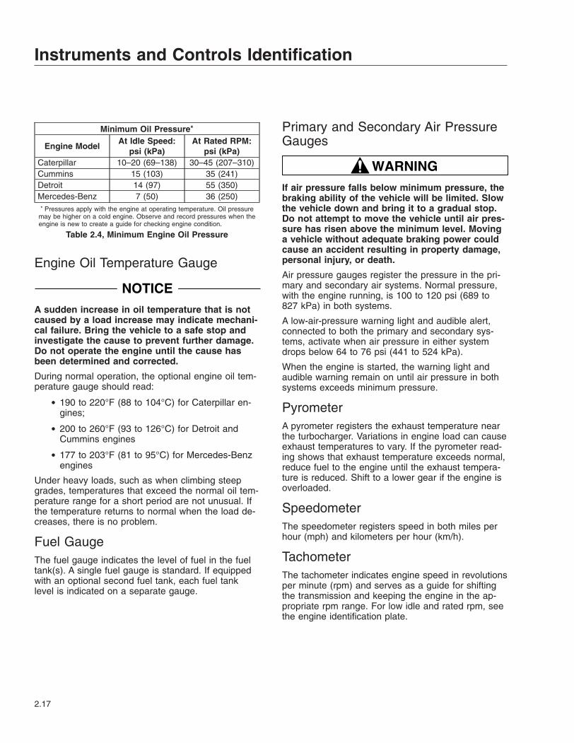
Minimum Oil Pressure*
Engine ModelAt Idle Speed:
psi (kPa)At Rated RPM:
psi (kPa)Caterpillar 10–20 (69–138) 30–45 (207–310)Cummins 15 (103) 35 (241)Detroit 14 (97) 55 (350)Mercedes-Benz 7 (50) 36 (250)* Pressures apply with the engine at operating temperature. Oil pressure
may be higher on a cold engine. Observe and record pressures when theengine is new to create a guide for checking engine condition.
Table 2.4, Minimum Engine Oil Pressure
Engine Oil Temperature Gauge
NOTICEA sudden increase in oil temperature that is notcaused by a load increase may indicate mechani-cal failure. Bring the vehicle to a safe stop andinvestigate the cause to prevent further damage.Do not operate the engine until the cause hasbeen determined and corrected.
During normal operation, the optional engine oil tem-perature gauge should read:
• 190 to 220°F (88 to 104°C) for Caterpillar en-gines;
• 200 to 260°F (93 to 126°C) for Detroit andCummins engines
• 177 to 203°F (81 to 95°C) for Mercedes-Benzengines
Under heavy loads, such as when climbing steepgrades, temperatures that exceed the normal oil tem-perature range for a short period are not unusual. Ifthe temperature returns to normal when the load de-creases, there is no problem.
Fuel GaugeThe fuel gauge indicates the level of fuel in the fueltank(s). A single fuel gauge is standard. If equippedwith an optional second fuel tank, each fuel tanklevel is indicated on a separate gauge.
Primary and Secondary Air PressureGauges
WARNINGIf air pressure falls below minimum pressure, thebraking ability of the vehicle will be limited. Slowthe vehicle down and bring it to a gradual stop.Do not attempt to move the vehicle until air pres-sure has risen above the minimum level. Movinga vehicle without adequate braking power couldcause an accident resulting in property damage,personal injury, or death.
Air pressure gauges register the pressure in the pri-mary and secondary air systems. Normal pressure,with the engine running, is 100 to 120 psi (689 to827 kPa) in both systems.
A low-air-pressure warning light and audible alert,connected to both the primary and secondary sys-tems, activate when air pressure in either systemdrops below 64 to 76 psi (441 to 524 kPa).
When the engine is started, the warning light andaudible warning remain on until air pressure in bothsystems exceeds minimum pressure.
PyrometerA pyrometer registers the exhaust temperature nearthe turbocharger. Variations in engine load can causeexhaust temperatures to vary. If the pyrometer read-ing shows that exhaust temperature exceeds normal,reduce fuel to the engine until the exhaust tempera-ture is reduced. Shift to a lower gear if the engine isoverloaded.
SpeedometerThe speedometer registers speed in both miles perhour (mph) and kilometers per hour (km/h).
TachometerThe tachometer indicates engine speed in revolutionsper minute (rpm) and serves as a guide for shiftingthe transmission and keeping the engine in the ap-propriate rpm range. For low idle and rated rpm, seethe engine identification plate.
Instruments and Controls Identification
2.17
Transmission Fluid TemperatureGaugeThe transmission fluid temperature gauge indicatesthe transmission lubricant operating temperature.Temperatures vary by application, but the transmis-sion fluid temperature gauge reading should not ex-ceed 250°F (121°C).
Under heavy loads, such as when climbing steepgrades, temperatures that exceed the normal oil tem-perature range for a short period are not unusual. Ifthe temperature returns to normal when the load de-creases, there is no problem.
NOTICEA sudden increase in transmission fluid tempera-ture that is not caused by a load increase mayindicate mechanical failure. Bring the vehicle to asafe stop and investigate the cause to preventfurther damage. Do not operate the vehicle untilthe cause has been determined and corrected.
Turbocharger Boost Pressure GaugeA turbocharger boost pressure gauge indicates thepressure in the intake manifold, in excess of atmos-pheric pressure, being created by the turbocharger.
VoltmeterThe voltmeter indicates the vehicle charging systemvoltage when the engine is running and the batteryvoltage when the engine is off. By monitoring thevoltmeter, the driver can stay aware of potential bat-tery charging problems and have them fixed beforethe batteries discharge enough to create starting diffi-culties. Vehicles are equipped with either a voltmetergauge, or a digital voltmeter readout located on thebottom line of the dash message center.
The voltmeter will normally show approximately 13.7to 14.1 volts when the engine is running. The voltageof a fully charged battery is 12.7 to 12.8 volts whenthe engine is off. Battery voltage under 12.0 volts isconsidered a low battery, and a completely dis-charged battery will produce only about 11.0 volts.
If the voltmeter shows an undercharged or over-charged condition for an extended period, have thecharging system and batteries checked at an autho-rized Freightliner service facility.
On a vehicle equipped with a battery isolator system,the voltmeter measures the average voltage of all thebatteries when the engine is running. When the en-gine is off, the voltmeter shows only the isolated bat-tery voltage and does not indicate the voltage of theengine-starting batteries.
ControlsControls and switches are listed here in alphabeticalorder.
Axle SwitchesDifferential Lock SwitchThe differential lock switch provides maximum trac-tion for slippery conditions by forcing the wheels oneach drive axle governed by the switch to rotate to-gether. Engagement can be at any speed, providedthe wheels are not slipping or spinning. SeeFig. 2.19.
Interaxle Lock SwitchThe interaxle lock, standard on all dual-drive ve-hicles, is driver-actuated by means of a LOCK/UNLOCK control valve switch. See Fig. 2.19. A redindicator illuminates when the interaxle lock is en-gaged.
NOTICEThe interaxle lock should only be engaged whenthe vehicle is moving slowly at low throttle. En-gagement at high speed or power can damagethe axle(s).
Do not permit rear wheels to spin freely for morethan ten seconds when traction is lost. Shift intoLOCK to prevent damage to interaxle and maindifferentials.
Brake ControlsNOTE: See Chapter 6 for detailed informationabout brake systems.
Instruments and Controls Identification
2.18

Parking Brake Control Valve
NOTICEDo not step on the service brake pedal while theparking brakes are applied. To do so can causedamage to the brake mechanisms.
The yellow diamond-shaped knob operates the park-ing brake valve. See Fig. 2.20. Pull the knob out toapply the tractor and the trailer spring parkingbrakes. Push the knob in to release the spring park-ing brakes. Before the spring parking brakes can bereleased, the air pressure in either air brake systemmust be at least 65 psi (447 kPa).
If the trailer is not equipped with spring parkingbrakes, pull the parking brake valve out to apply thetractor parking brakes and the trailer service brakes.
Trailer Air Supply ValveThe red octagonal-shaped knob operates the trailerair supply valve, which charges the trailer air supplysystem and releases the trailer spring parkingbrakes. See Fig. 2.20.
After the vehicle and its air hoses are connected to atrailer and the pressure in the air system is at least65 psi (447 kPa), push the trailer air supply valveknob in (and leave it in) to charge the trailer air sup-ply system and release the trailer spring parkingbrakes. Pull the trailer air supply valve out beforedisconnecting a trailer or when operating a vehiclewithout a trailer.
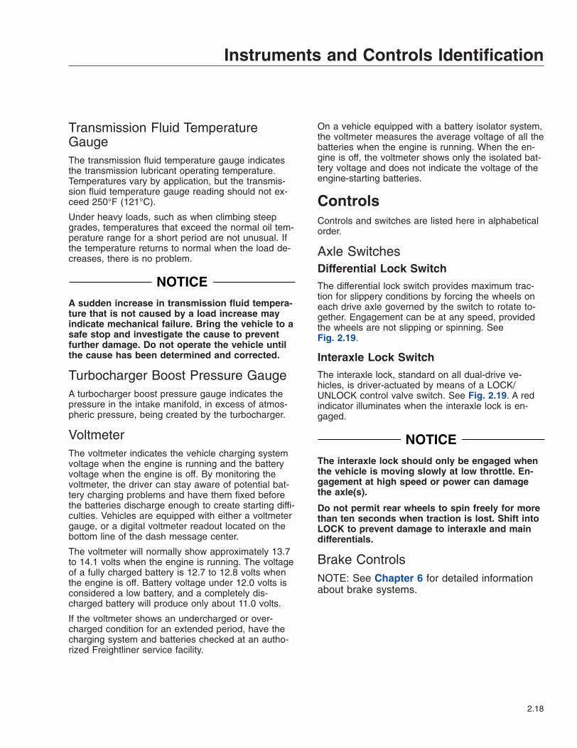
Trailer Brake LeverThe trailer brake lever is used to apply the trailer ser-vice brakes without applying the truck or tractor ser-vice brakes. It is usually mounted on the right-handcontrol panel. See Fig. 2.21. The valve can be par-tially or fully applied, but in any partially on position itwill be overridden by a full application of the servicebrake pedal. Move the lever down to apply the trailerbrakes; move the lever up to release the trailerbrakes. The lever will automatically return to the upposition when it is released.
Engine Brake SwitchThe Hi/Med/Lo engine brake 3-position switch con-trols the amount of engine braking. Press the lowerthird of the switch for low, center for medium, andupper third for high. See Fig. 2.22.
1
2
3
4
01/05/2012 f611158
1. Interaxle Differential Lock Switch2. Fifth Wheel Slide Switch3. Rearmost Axle Differential Lock Switch4. Air Suspension Dump Control Switch
Fig. 2.19, Axle and Suspension Switches
f610291
1 2
03/10/99
1. Trailer Air Supply Valve (red knob)2. Parking Brake Control Valve (yellow knob)
Fig. 2.20, Brake Valve Control Knobs
Instruments and Controls Identification
2.19
Cruise Control Switches
WARNINGDo not use the cruise control system when driv-ing conditions do not permit maintaining a con-stant speed, such as in heavy traffic or on roadsthat are winding, icy, snow-covered, slippery, orroads with a loose driving surface. Failure to fol-low this precaution could cause a collision orloss of vehicle control, possibly resulting in per-sonal injury or property damage.
NOTICEWhen the cruise control is engaged, do not at-tempt to shift gears without using the clutchpedal. Failure to follow this precaution will resultin a temporarily uncontrolled increase in enginespeed. Transmission damage and gear strippingcould result.
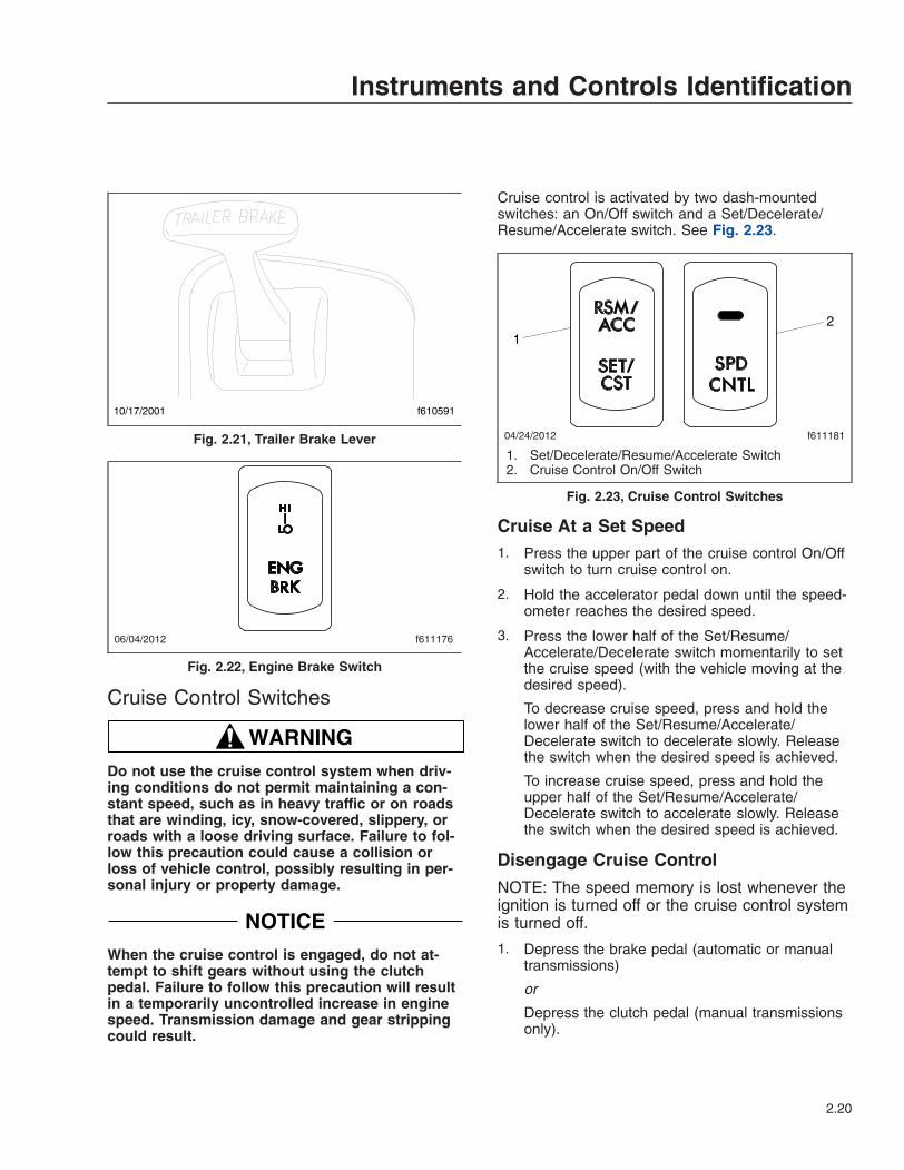
Cruise control is activated by two dash-mountedswitches: an On/Off switch and a Set/Decelerate/Resume/Accelerate switch. See Fig. 2.23.
Cruise At a Set Speed1. Press the upper part of the cruise control On/Off
switch to turn cruise control on.
2. Hold the accelerator pedal down until the speed-ometer reaches the desired speed.
3. Press the lower half of the Set/Resume/Accelerate/Decelerate switch momentarily to setthe cruise speed (with the vehicle moving at thedesired speed).
To decrease cruise speed, press and hold thelower half of the Set/Resume/Accelerate/Decelerate switch to decelerate slowly. Releasethe switch when the desired speed is achieved.
To increase cruise speed, press and hold theupper half of the Set/Resume/Accelerate/Decelerate switch to accelerate slowly. Releasethe switch when the desired speed is achieved.
Disengage Cruise Control
NOTE: The speed memory is lost whenever theignition is turned off or the cruise control systemis turned off.
1. Depress the brake pedal (automatic or manualtransmissions)
or
Depress the clutch pedal (manual transmissionsonly).
10/17/2001 f610591
Fig. 2.21, Trailer Brake Lever
f61117606/04/2012
Fig. 2.22, Engine Brake Switch
f61118104/24/2012
12
1. Set/Decelerate/Resume/Accelerate Switch2. Cruise Control On/Off Switch
Fig. 2.23, Cruise Control Switches
Instruments and Controls Identification
2.20

2. Press the lower half of the On/Off switch.
NOTE: To resume the preselected cruise speed,increase vehicle speed to above minimumcruise control speed and momentarily press theupper half of the Set/Resume/Accelerate/Decelerate switch. Cruise will return to the lastspeed selected.
Engine Fan SwitchTo turn the engine fan on, press the upper half of theengine fan switch. See Fig. 2.24. The fan will con-tinue to operate for a set amount of time and thenturn off unless the coolant temperature is highenough to continue fan operation. To turn the fan offbefore the set time period ends, press the lower halfof the switch.
Ignition SwitchThe ignition switch has four positions: OFF, ACC (ac-cessory), ON, and START. See Fig. 2.25. The igni-tion key also locks and unlocks the cab doors, bag-gage door(s), and if equipped, the bunk door(s).
In the OFF position, the ignition switch is vertical.The key can be inserted and removed only in theOFF position.
The following functions are operable when the igni-tion switch is in the OFF position (regardless ofwhether the key is inserted):
• low-beam headlights
• taillights
• brake lights
• road lights
• dome lights
• clearance lights
• hazard warning lights
• turn signals
• utility lights
• baggage compartment lights
• spotlights
• horn
• clock
• refrigerator
• CB radio
• power mirrors
• power receptacle
• fuel heater
• electric oil pan heater
• electric or diesel-fired engine coolant pre-heater
Turn the key counterclockwise to reach the ACC po-sition. In addition to all the functions that are oper-able in the OFF position, the following functions areoperable when the switch is in the ACC position:
• radio/stereo system
• heater and A/C fan
• mirror defog
• windshield fan
f61117804/24/2012
Fig. 2.24, Engine Fan Switch
07/19/2006 f610805
Fig. 2.25, Ignition Switch
Instruments and Controls Identification
2.21

• ether start system
• air dryer
• backup lights
Turn the key clockwise past the OFF position toreach the ON position. When the ignition is turnedon, the following actions should occur:
• electronic gauges complete a full sweep oftheir dials
• warning and indicator lamps illuminate, thenare extinguished
• audible alert sounds for approximately fourseconds or until sufficient air pressure buildsup in the primary and secondary air systems
• software revision level of the ICU is displayedon the driver message center, followed by anyactive faults
IMPORTANT: Do not crank the engine until theICU gauge sweep is complete.
Turn the key clockwise past the ON position to reachthe START position to start the engine. Release thekey the moment the engine starts. Do not operatethe starter longer than thirty seconds, then allow thestarter to cool between attempts. If the starter over-heats, the starter protection system will prevent op-eration of the starter until it has cooled. Release thekey the moment the engine starts.
Lighting ControlsExterior Lighting ControlsExterior light controls are listed here in alphabeticalorder.
Backup LightsBackup lights provide a warning to pedestrians andother drivers that the vehicle is, or is about to, backup.
Daytime Running LightsThe daytime running lights (DRL), if equipped, areautomatically activated when the ignition is switchedon and the parking brake is released. The DRL oper-ate until the parking brake is applied or the head-lights are turned on.
Some vehicles may be equipped with a momentaryDRL override switch. See Fig. 2.26. Press the upperhalf of the switch to briefly deactivate the DRL.
Fog LightsFog lights are designed to reduce glare in foggy con-ditions. The low-beam headlights must be on in orderto turn the fog lights on. Press the upper half of theswitch to activate the fog lights. See Fig. 2.26.
Hazard Warning LightsThe hazard warning light switch tab is located belowthe turn signal lever. Pull the tab out to activate thehazard warning lights. When the hazard warninglights flash, all turn signal lamps and both of the indi-cator lights on the control panel will flash. Move theturn signal lever up or down to cancel the warninglights.
HeadlightsA three-position paddle switch is used to operate theexterior lights. See Fig. 2.26. Move the paddle switchup to activate the headlights, instrument panel, clear-ance lights, marker lights, and taillights. To deactivateall vehicle lighting, ensure the switch is in the middleposition. Move the paddle switch down to activateonly the clearance, instrument panel, marker lights,and the taillights.
High-Beam HeadlightsTo activate the high-beam headlights, pull the turnsignal lever towards the driver while the low-beamheadlights are on. Pull the turn signal lever backagain to deactivate the high beams and return to lowbeam headlights.
When the high-beam headlights are on, a blue lightilluminates on the instrument cluster.
NOTE: The ignition switch must be on for thehigh beams to work.
Marker Light InterruptA momentary interrupt switch temporarily deactivatesthe marker lights and taillights. With the vehicle lightson, press and release the interrupt switch to brieflyturn the marker lights and taillights off. To alert thedriver that the switch is functioning, the dash lightswill flash with the marker lights when the switch isactuated.
Instruments and Controls Identification
2.22
Road LightsPress the upper half of the road light switch to acti-vate the road lights mounted on the bottom edge ofthe front bumper or recessed in the front bumper.See Fig. 2.26.
SpotlightThe spotlight switch is located on the pivoting handleof the spotlight. There may be a single spotlight as-sembly mounted above the driver’s door, or oneabove each door.
Turn SignalsThe turn signal lever is mounted on the steering col-umn. Push the lever down to activate the left-turnsignal lights; pull the lever up to activate the right-turn signal lights. To manually cancel the signal,move the lever to the neutral position. When a turn
signal is activated, a green indicator light flashes onthe instrument cluster.
Utility LightsUtility lights can be swivel-mounted on top of thecab, mounted on the intake/exhaust support, or flush-mounted in the back of the cab or sleeper. Press theupper half of the switch to activate the utility lights.See Fig. 2.26. Press the lower half of the switch toturn the utility lights off. When activated, a red indica-tor light in the switch is illuminated, if equipped
Interior Lighting ControlsInterior light controls are listed here in alphabeticalorder.
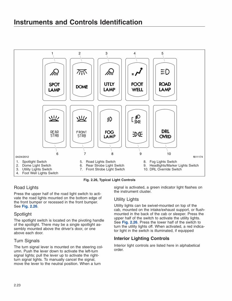
6 7 8 9 10
1 2 3 4 5
04/24/2012 f611174
1. Spotlight Switch2. Dome Light Switch3. Utility Lights Switch4. Foot Well Lights Switch
5. Road Lights Switch6. Rear Strobe Light Switch7. Front Strobe Light Switch
8. Fog Lights Switch9. Headlights/Marker Lights Switch10. DRL Override Switch
Fig. 2.26, Typical Light Controls
Instruments and Controls Identification
2.23

Baggage Compartment LightsBaggage compartment lights are located on the un-derside of the lower bunk, on both sides. Both lightsturn on when either baggage compartment door isopened to illuminate the baggage compartment. Thelights also come on when the lower bunk is raised.
Cab Overhead Console LightsThe overhead console includes a clear reading light,a clear dome light, and a red map light. The domelights illuminate when a door opens, then stay on fora short time after both doors are closed. Press thelens of the reading light, dome light, or map light toactivate each one.
Foot Well LightsWhen the driver or passenger doors are opened, redlights illuminate both foot wells. These lights can alsobe activated with the foot well light switch. SeeFig. 2.26. Press the upper half of the switch to turnthe foot well lights on, press the lower half of theswitch to turn them off.
The sleeper foot well switch is located in the lowerswitch module in the sleeper. It looks identical to thecab foot well switch. See Fig. 2.26. When the switchis activated, two lights illuminate the sleeper floor.
Instrument Panel LightsThe instrument panel lights illuminate when theheadlights are turned on. When the headlights areon, the panel lamp switch controls the intensity of theinstrument panel lamps. Slide the switch up tobrighten them and down to dim them. When theheadlights are turned on, the panel lights setting willdefault to the intensity that was last set.
Rear-Wall Dome LightA rear-wall dome light is available on all sleepercabs. It is located on the rear wall where the wallmeets the roof. To turn on the rear-wall fluorescentlight, press the dome light switch on either the loweror upper bunk control panels.
Sleeper Dome LightA sleeper dome light is located on the roof, betweenthe bunk and the cab on sleeper vehicles. The rearcab dome light will activate with the dome lightswhen a door is opened, then stay on for a short timeafter both doors are closed. Use the dash-mounted
switch or the switch in the sleeper panel to activatethe rear cab dome light. See Fig. 2.26.
Sleeper Reading LightsClear reading lights are mounted above the lowerbunk in the rear corners of the sleeper. There aretwo switches in the sleeper control panel for thereading lights. To turn a reading light on, press theupper half of the switch. Press the lower half of theswitch to turn it off.
The reading lights can also be activated by pressingthe lens.
PTO SwitchTo activate the PTO function, press the upper half ofthe switch. Press the lower half of the switch to de-activate the PTO function.
Steering Column Tilt/TelescopeControl
WARNINGMake sure that the steering column is locked be-fore driving the vehicle. Never tilt the columnwhile driving the vehicle. Doing so could causeloss of vehicle control, personal injury, and prop-erty damage.
Adjust the seat to the desired ride position, then tiltor telescope the steering column as needed.
To tilt the steering column, press down on the footpedal located on the steering column. Tilt the steer-ing column up or down to the desired position. Re-lease the foot pedal to lock the steering column inplace.
To telescope the steering column, press down on thefoot pedal located on the steering column. Pull thesteering wheel closer to you or push the steeringwheel away from you. Release the foot pedal to lockthe steering column in place.
Instruments and Controls Identification
2.24
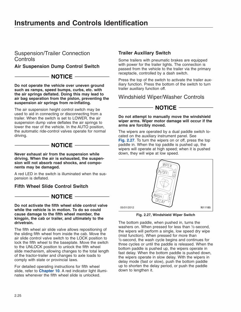
Suspension/Trailer ConnectionControlsAir Suspension Dump Control Switch
NOTICEDo not operate the vehicle over uneven groundsuch as ramps, speed bumps, curbs, etc. withthe air springs deflated. Doing this may lead toair bag separation from the piston, preventing thesuspension air springs from re-inflating.
The air suspension height control switch may beused to aid in connecting or disconnecting from atrailer. When the switch is set to LOWER, the airsuspension dump valve deflates the air springs tolower the rear of the vehicle. In the AUTO position,the automatic ride-control valves operate for normaldriving.
NOTICENever exhaust air from the suspension whiledriving. When the air is exhausted, the suspen-sion will not absorb road shocks, and compo-nents may be damaged.
A red LED in the switch is illuminated when the sus-pension is deflated.
Fifth Wheel Slide Control Switch
NOTICEDo not activate the fifth wheel slide control valvewhile the vehicle is in motion. To do so couldcause damage to the fifth wheel member, thekingpin, the cab or trailer, and ultimately to thedrivetrain.
The fifth wheel air slide valve allows repositioning ofthe sliding fifth wheel from inside the cab. Move theair slide control valve switch to the LOCK position tolock the fifth wheel to the baseplate. Move the switchto the UNLOCK position to unlock the fifth wheelslide mechanism, allowing changes to the total lengthof the tractor-trailer and changes to axle loads tocomply with state or provincial laws.
For detailed operating instructions for fifth wheelslide, refer to Chapter 10. A red indicator light illumi-nates whenever the fifth wheel slide is unlocked.
Trailer Auxiliary SwitchSome trailers with pneumatic brakes are equippedwith power for the trailer lights. The connection ispassed from the vehicle to the trailer via the primaryreceptacle, controlled by a dash switch.
Press the top of the switch to activate the trailer aux-iliary function. Press the bottom of the switch to turntrailer auxiliary function off.
Windshield Wiper/Washer Controls
NOTICEDo not attempt to manually move the windshieldwiper arms. Wiper motor damage will occur if thearms are forcibly moved.
The wipers are operated by a dual paddle switch lo-cated on the auxiliary instrument panel. SeeFig. 2.27. To turn the wipers on or off, press the toppaddle in. When the top paddle is pushed up, thewipers will operate at high speed; when it is pusheddown, they will wipe at low speed.
The bottom paddle, when pushed in, turns thewashers on. When pressed for less than ½-second,the wipers will perform a single, low speed dry wipe(mist function). When pressed for more than½-second, the wash cycle begins and continues forthree cycles or until the paddle is released. When thebottom paddle is pushed up, the wipers operate infast delay. When the bottom paddle is pushed down,the wipers operate in slow delay. With the wipers indelay mode (fast or slow), push the bottom paddleup to shorten the delay period, or push the paddledown to lengthen it.
05/01/2012 f611185
Fig. 2.27, Windshield Wiper Switch
Instruments and Controls Identification
2.25
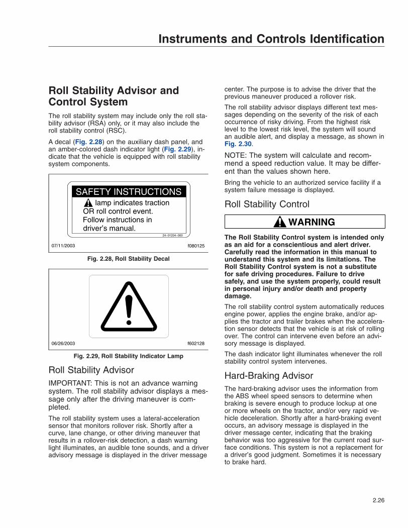
Roll Stability Advisor andControl SystemThe roll stability system may include only the roll sta-bility advisor (RSA) only, or it may also include theroll stability control (RSC).
A decal (Fig. 2.28) on the auxiliary dash panel, andan amber-colored dash indicator light (Fig. 2.29), in-dicate that the vehicle is equipped with roll stabilitysystem components.
Roll Stability AdvisorIMPORTANT: This is not an advance warningsystem. The roll stability advisor displays a mes-sage only after the driving maneuver is com-pleted.
The roll stability system uses a lateral-accelerationsensor that monitors rollover risk. Shortly after acurve, lane change, or other driving maneuver thatresults in a rollover-risk detection, a dash warninglight illuminates, an audible tone sounds, and a driveradvisory message is displayed in the driver message
center. The purpose is to advise the driver that theprevious maneuver produced a rollover risk.
The roll stability advisor displays different text mes-sages depending on the severity of the risk of eachoccurrence of risky driving. From the highest risklevel to the lowest risk level, the system will soundan audible alert, and display a message, as shown inFig. 2.30.
NOTE: The system will calculate and recom-mend a speed reduction value. It may be differ-ent than the values shown here.
Bring the vehicle to an authorized service facility if asystem failure message is displayed.
Roll Stability Control
WARNINGThe Roll Stability Control system is intended onlyas an aid for a conscientious and alert driver.Carefully read the information in this manual tounderstand this system and its limitations. TheRoll Stability Control system is not a substitutefor safe driving procedures. Failure to drivesafely, and use the system properly, could resultin personal injury and/or death and propertydamage.
The roll stability control system automatically reducesengine power, applies the engine brake, and/or ap-plies the tractor and trailer brakes when the accelera-tion sensor detects that the vehicle is at risk of rollingover. The control can intervene even before an advi-sory message is displayed.
The dash indicator light illuminates whenever the rollstability control system intervenes.
Hard-Braking AdvisorThe hard-braking advisor uses the information fromthe ABS wheel speed sensors to determine whenbraking is severe enough to produce lockup at oneor more wheels on the tractor, and/or very rapid ve-hicle deceleration. Shortly after a hard-braking eventoccurs, an advisory message is displayed in thedriver message center, indicating that the brakingbehavior was too aggressive for the current road sur-face conditions. This system is not a replacement fora driver’s good judgment. Sometimes it is necessaryto brake hard.
lamp indicates tractionOR roll control event.Follow instructions indriver’s manual.
24−01204−000
07/11/2003 f080125
SAFETY INSTRUCTIONS
Fig. 2.28, Roll Stability Decal
06/26/2003 f602128
Fig. 2.29, Roll Stability Indicator Lamp
Instruments and Controls Identification
2.26

From the highest risk level to the lowest risk level,the system will sound an audible alert, and display amessage, as shown in Fig. 2.30.
Trip/Leg TotalsThe driver message center records the number ofmessages received, and displays the number ofmessages as counts. Roll stability advisor (RSA) andhard-braking event data (HBED) counts can beviewed in the trip advisory screen, and the leg advi-sory screen.
Counts can be reset using the + key on the steeringwheel. Clearing RSA and HBED leg counts will alsoreset the leg miles and leg hours. Clearing RSA andHBED trip counts will also reset trip miles, trip hours,leg miles, leg hours, and leg advisory counts. In ad-dition, resetting leg miles will clear leg counts. Clear-ing trip miles will reset miles, hours, and counts inboth the leg and trip screens.
The TRIP and LEG advisor screens count both theroll stability advisories (ROLL) and hard-brakingevents (BRK). For example, if during a TRIP, thedriver message center recorded the events inTable 2.5, the message center would display asshown in Fig. 2.31.
RSA/HBED CountMessage Received Message Counts
RSA Level 3 2RSA Level 2 3RSA Level 1 7
HBED Level 3 5HBED Level 2 1HBED Level 1 8
Table 2.5, RSA/HBED Count
If the count reaches more than 9 occurrences an up-arrow symbol will appear, to indicate to the driverthat the count has exceeded 9 counts. SeeFig. 2.32.
Message to Display
4 1
MessageMSG
No.
System Fault1WARNING
RAC SYSTEM FAIL
ACTIVE SLOWING
ROLLOVER RISK
4 NoneRSC2
VERY HIGH RISK OF
ROLLOVER DETECTED
REDUCE SPEED
AT LEAST 11 KPH
REDUCE SPEED
AT LEAST 7 MPH
or in metric
19.6 10RSA Level 33
HIGH RISK OF
ROLLOVER DETECTED
REDUCE SPEED
AT LEAST 11 KPH
REDUCE SPEED
AT LEAST 7 MPH
or in metric
14 5RSA Level 24
ROLLOVER RISK
DETECTED
REDUCE SPEED
AT LEAST 11 KPH
or in metric
REDUCE SPEED
AT LEAST 7 MPH
8.4 2RSA Level 15
HARD BRAKING WITH
ABS ACTIVATED
LOOK AHEAD
BRAKE SOONER
14 0.5HBED Level 36
HARD BRAKING
DETECTED
LOOK AHEAD
BRAKE SOONER
14 0.5HBED Level 27
LOSS OF TRACTION
ABS ACTIVATED
ROAD SURFACE
MAY BE POOR
14 0.5HBED Level 18
07/25/2008 f040769
DisplayTime:
Seconds
BuzzerTime:
Seconds
Fig. 2.30, Roll Stability and Hard-Braking Warnings
07/25/2008
TRIP ADVISORIES
237 ROLL 518 BRK
f040770A B C D E F
A. RSA lev. 3 Count (2)B. RSA lev. 2 Count (3)C. RSA lev. 1 Count (7)
D. HBED lev. 3 Count (5)E. HBED lev. 2 Count (1)F. HBED lev. 1 Count (8)
Fig. 2.31, Trip Advisor Message Screen
Instruments and Controls Identification
2.27
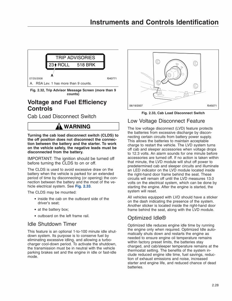
Voltage and Fuel EfficiencyControlsCab Load Disconnect Switch
WARNINGTurning the cab load disconnect switch (CLDS) tothe off position does not disconnect the connec-tion between the battery and the starter. To workon the vehicle safely, the negative leads must bedisconnected from the battery.
IMPORTANT: The ignition should be turned offbefore turning the CLDS to on or off.
The CLDS is used to avoid excessive draw on thebattery when the vehicle is parked for an extendedperiod of time by disconnecting (or opening) the con-nection between the battery and the most of the ve-hicle electrical system. See Fig. 2.33.
The CLDS may be mounted:
• inside the cab on the outboard side of thedriver’s seat;
• at the battery box;
• outboard on the left frame rail.
Idle Shutdown TimerThis feature is an optional 1-to-100 minute idle shut-down system. Its purpose is to conserve fuel byeliminating excessive idling, and allowing a turbo-charger cool-down period. To activate the shutdown,the transmission must be in neutral with the vehicleparking brakes set and the engine in idle or fast-idlemode.
Low Voltage Disconnect FeatureThe low voltage disconnect (LVD) feature protectsthe batteries from excessive discharge by discon-necting certain circuits from battery power supply.This allows the batteries to maintain acceptablecharge to restart the vehicle. The LVD system turnsoff cab and sleeper accessories when voltage dropsto 12.3 volts. An alarm sounds for one minute beforeaccessories are turned off. If no action is taken withinthat minute, the LVD module will shut off power topredetermined cab and sleeper circuits and illuminatean LED indicator on the LVD module located insidethe right-hand door frame behind the seat. Thesecircuits will remain off until the LVD measures 13.0volts on the electrical system, which can be done bystarting the engine. After the engine is started, thesystem will reset.
All vehicles equipped with LVD should have a stickeron the dash indicating the presence of the system.Another sticker is located inside the right-hand doorframe behind the seat, along with the LVD module.
Optimized Idle®Optimized Idle reduces engine idle time by runningthe engine only when required. Optimized Idle auto-matically shuts down and restarts the engine asneeded to ensure engine oil temperature remainswithin factory preset limits, the batteries staycharged, and cab/sleeper temperature remains at thethermostat setting. The benefits of the system in-clude reduced engine idle time, fuel savings, reduc-tion of exhaust emissions and noise, increasedstarter and engine life, and reduced chance of deadbatteries.
07/25/2008
TRIP ADVISORIES
23 ROLL 518 BRK
f040771A
A. RSA Lev. 1 has more than 9 counts.
Fig. 2.32, Trip Advisor Message Screen (more than 9counts)
06/19/2007 f545071
Fig. 2.33, Cab Load Disconnect Switch
Instruments and Controls Identification
2.28

Vehicles equipped with Optimized Idle have a labelon the dash, and a telltale (OPT IDLE) in the ICU.See Fig. 2.34 for the dash label detail. If equipped, athermostat is located above the sleeper bunk. SeeFig. 2.35.
Optimized Idle operates in two modes:
• Engine mode: Keeps the battery charged andengine oil temperature between 60 and 104°F(16 to 40°C).
• Thermostat mode (activated when the optionalthermostat is turned on): Keeps the cab andsleeper at a constant preset temperature, in
addition to all functions available in enginemode.
Thermostat mode controls the set point, which is thedesired temperature of the cab and sleeper, and thecomfort zone, which is the allowed temperature de-viation from the set point before the engine starts.
The thermostat display defaults to show the tempera-ture of the sleeper, but changes accordingly as thebuttons are pressed.
The button functions are as follows:
• Up arrow: Increases the set point and comfortzone (allowed temperature variation).
• Down arrow: Decreases the set point and com-fort zone.
• Cool/Heat: Sets either cooling or heating op-eration.
• MODE: Scrolls through the various functions. Itcan also be used to set desired temperaturevalues.
If a vehicle has Optimized Idle, the following func-tions will not operate with the key in accessorymode. Optimized Idle may also turn these functionsoff to reduce stress on the batteries.
• Cab climate control fan
• Sleeper climate control fan
• Mirror heat
• Fuel/water separator heat
• Seat heat
• Advertising light
• Auxiliary circulation fan (windshield)
• Air dryer
1. To activate Optimized Idle (engine mode):
1.1 Set the parking brake.
1.2 If it is open, close and secure the hood.
1.3 Start the engine and let it idle.
1.4 Put the transmission in neutral.
1.5 Turn on the cruise control.
The OPT IDLE lamp will blink, indicatingthat Optimized Idle is active. The systemis now in engine mode and after an initial
11/13/96 f080062
TO AVOIDUNINTENTIONAL
VEHICLE MOVEMENT,DO NOT MOVE SHIFT
LEVER OR RANGESELECTOR WHEN
OPTIMIZED IDLE IS ON
OPTIMIZED IDLETM
TO USE:− IDLE ENGINE− CLOSE HOOD− ENGAGE PARKING BRAKES− PUT TRANSMISSION IN
NEUTRAL ANDHI RANGE (IF EQUIPPED)
− THEN, MOVE CRUISE SWITCHFROM OFF TO ON
− IF DESIRED, TURN CABTHERMOSTAT ON (IF EQUIPPED)
Fig. 2.34, Optimized Idle Dash Label
MODE
°F
°C
11/08/96
1
2
3 4 5
6
7
8
910 f601250
1. Down Arrow Button2. Up Arrow Button3. Upper/Lower
Temperature Icon4. Temperature Display5. Degrees Fahrenheit
Indicator
6. MODE Button7. Cooling Icon8. Cool/Heat Selection
Button9. Heating Icon10. Degrees Celsius
Indicator
Fig. 2.35, Optimized Idle Thermostat
Instruments and Controls Identification
2.29

phase, in which the idle speeds up to1000 rpm, the engine will stop and startautomatically to keep the battery chargedand the engine oil warm.
IMPORTANT: The cruise control must beturned on once the engine is idling. If it waspreviously turned on, turn the cruise controloff, then turn it on again.
2. Activate thermostat mode, if equipped.
NOTE: When the system is in thermostatmode, it is also in engine mode. It will con-tinue to operate in engine mode even if ther-mostat mode is turned off.
2.1 With the system in engine mode, set thecab and sleeper heater or air conditionercontrols to the highest setting.
2.2 Turn on the thermostat by touching any ofthe four buttons. See Fig. 2.35.
The display will flash the current sleepertemperature and the previous mode (cool-ing or heating) selected. If the cab needsto be cooled or heated, the cool/heat iconwill flash.
2.3 Choose either cool or heat by pressing theCool/Heat button. Make sure the selectionmatches that of the cab controls.
IMPORTANT: If the heat or cool selection ofthe thermostat does not match that of thecab controls, the system will idle and cycleexcessively.
2.4 Select Fahrenheit or Celsius by pressingand holding the MODE button until eitherthe "F" or "C" is displayed.
2.5 Select the temperature set point by press-ing the up or down arrows, as applicable.Holding the button will cause the displayto scroll up or down rapidly. When the de-sired set point is displayed, release thebutton. The set point is stored in memory.
2.6 Select the temperature comfort zone bypressing the MODE button until the upperand lower temperature limit icon is dis-played. Then use the up or down arrow toselect one of the three comfort zones: 4°F(2°C), 7°F (4°C), or 10°F (6°C).
3. To deactivate thermostat mode and return to justengine mode, press and hold the MODE buttonfor three seconds.
4. To shut down Optimized Idle completely, eitherturn off the ignition or use the drive away feature.
The drive away feature allows the use of all theengine features. Use the drive away feature asfollows:
4.1 If the engine is running: Release the park-ing brakes or put the transmission in gear.
If the engine is not running: Start the en-gine. Release the parking brakes or putthe transmission into gear.
4.2 Let the engine return to base idle. Theactive light will turn off. Optimized Idle isnow disabled.
Meritor WABCO® AntilockBraking SystemThe Meritor WABCO Antilock Braking System (ABS)is an electronic wheel speed monitoring and controlsystem that works with the standard air brake sys-tem. ABS passively monitors vehicle wheel speed atall times, and controls wheel speed during emer-gency stops.
IMPORTANT: For proper ABS system operation,do not change tire sizes. The sizes of the tiresinstalled during production are programmed intothe electronic control unit. Installing different-sized tires could result in a reduced brakingforce, leading to longer stopping distances.
ABS includes signal-generating tone wheels and sen-sors located in the wheel hubs of each sensedwheel. The sensors transmit vehicle wheel speedinformation to an electronic control unit (located be-hind the center dash). The control unit’s main circuitinterprets the speed sensor signals and calculateswheel speed, wheel retardation, and a vehicle refer-ence speed. If the calculations indicate wheel lockup,the main circuit signals the appropriate modulatorvalve to reduce braking pressure. During emergencybraking, the modulator valve alternately reduces, in-creases, or maintains air pressure supply in thebrake chamber to prevent front and rear wheellockup.
Instruments and Controls Identification
2.30

The electronic control unit (ECU) also has a safetycircuit that constantly monitors the wheel sensors,traction control valve (if equipped), modulator valves,and the electrical circuitry.
The Meritor WABCO ABS combines one front-axlecontrol channel with one rear-axle control channel toform one control circuit. For example, the sensor andmodulator valve on the left-front axle form a controlcircuit with the sensor and modulator valve on theright-rear axle. If, during vehicle operation, the safetycircuit senses a failure in any part of the ABS, thevehicle ABS warning indicator illuminates and thecontrol circuit where the failure occurred is switchedto normal braking action. The remaining control cir-cuit will retain the ABS effect. Even if the ABS iscompletely inoperative, normal braking ability ismaintained. An exception would be if a modulatorvalve (or combination modulator valve) is damagedand inoperative. As these components are an integralpart of the air brake system, normal braking may beimpaired or inoperative.
During emergency or reduced-traction stops, fullydepress the brake pedal until the vehicle comes to asafe stop. Do not pump the brake pedal. With thebrake pedal fully depressed, the ABS will control allwheels to provide steering control and a reducedbraking distance.
Although the ABS improves vehicle control duringemergency braking situations, the driver still has theresponsibility to change driving styles depending onexisting traffic and road conditions. For example, theABS cannot prevent an accident if the driver isspeeding or following too closely.
Trailer ABS CompatibilityThe Meritor WABCO ABS is designed to communi-cate with a trailer ABS, if they are compatible. Com-patibility will result in the illumination of the trailerABS warning indicator during vehicle start-up andfault detection.
The trailer ABS warning indicator will not illuminateunless a compatible trailer is connected to the trac-tor. The dash-mounted lamp will operate as followswhen a compatible trailer is properly connected tothe tractor:
• When the ignition key is turned to the ON posi-tion, the trailer ABS warning indicator will illu-minate momentarily, then turn off.
• If the lamp illuminates momentarily during ve-hicle operation, then shuts off, a fault was de-tected and corrected.
• If the lamp illuminates and stays on during ve-hicle operation, there is a fault with the trailerABS. Repair the trailer ABS system immedi-ately to ensure full antilock braking capability.
IMPORTANT: If a compatible trailer is con-nected, and the lamp is not illuminating momen-tarily when the ignition key is turned to the ONposition, it is possible that the lamp is burnt out.
Automatic Traction ControlVehicles with electronic engines and ABS may haveAutomatic Traction Control (ATC). On these vehicles,the ATC system automatically limits wheel spin dur-ing reduced-traction situations. In normal braking ap-plications, the standard air brake system is in effect.
An additional solenoid valve is installed. Duringreduced-traction situations, the ATC solenoid valvecontrols air pressure to the modulator valves andthey in turn increase, hold, or reduce pressure to theappropriate brake chambers to provide better tractionwhenever wheel spin occurs.
When the ATC system is in the NORMAL mode, itwill apply gentle braking to the spinning wheel, tofeed power to the wheel(s) with better traction. Ifboth wheels are spinning, the system will signal theengine to reduce power.
ATC includes a deep snow and mud option to in-crease available traction on extra-soft surfaces likesnow, mud, or gravel. A rocker switch labeled ATC islocated on the dash. See Fig. 2.36. Pressing theswitch temporarily allows more drive wheel spin. Acti-vating the deep snow and mud option causes theWHEEL SPIN lamp to flash. Pressing the switchagain cycles the system back to normal operation.
NOTICEThe deep snow and mud option is intended to beused under specific slippery conditions that re-quire momentary increased wheel spin. Usingthis option for an extended period of time maydamage the vehicle brake system.
After the ignition switch is turned on, the vehicle ABSlamp and the WHEEL SPIN indicator lamp come onfor about three seconds. After three seconds, the
Instruments and Controls Identification
2.31
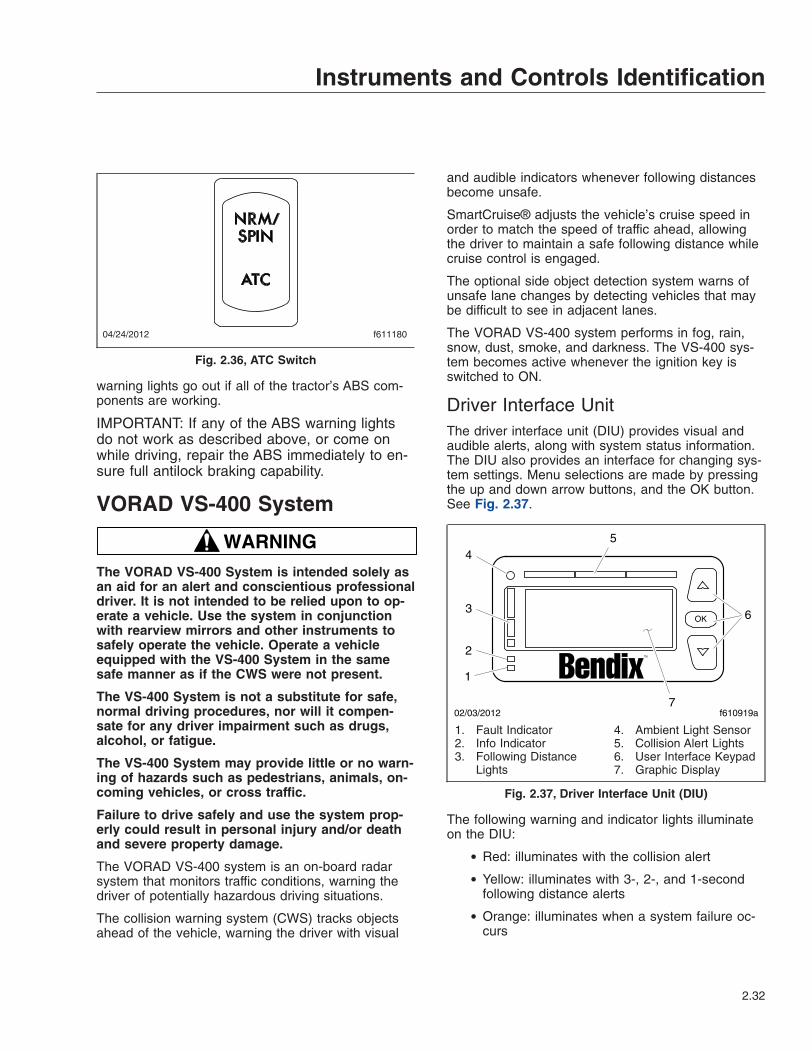
warning lights go out if all of the tractor’s ABS com-ponents are working.
IMPORTANT: If any of the ABS warning lightsdo not work as described above, or come onwhile driving, repair the ABS immediately to en-sure full antilock braking capability.
VORAD VS-400 System
WARNINGThe VORAD VS-400 System is intended solely asan aid for an alert and conscientious professionaldriver. It is not intended to be relied upon to op-erate a vehicle. Use the system in conjunctionwith rearview mirrors and other instruments tosafely operate the vehicle. Operate a vehicleequipped with the VS-400 System in the samesafe manner as if the CWS were not present.
The VS-400 System is not a substitute for safe,normal driving procedures, nor will it compen-sate for any driver impairment such as drugs,alcohol, or fatigue.
The VS-400 System may provide little or no warn-ing of hazards such as pedestrians, animals, on-coming vehicles, or cross traffic.
Failure to drive safely and use the system prop-erly could result in personal injury and/or deathand severe property damage.
The VORAD VS-400 system is an on-board radarsystem that monitors traffic conditions, warning thedriver of potentially hazardous driving situations.
The collision warning system (CWS) tracks objectsahead of the vehicle, warning the driver with visual
and audible indicators whenever following distancesbecome unsafe.
SmartCruise® adjusts the vehicle’s cruise speed inorder to match the speed of traffic ahead, allowingthe driver to maintain a safe following distance whilecruise control is engaged.
The optional side object detection system warns ofunsafe lane changes by detecting vehicles that maybe difficult to see in adjacent lanes.
The VORAD VS-400 system performs in fog, rain,snow, dust, smoke, and darkness. The VS-400 sys-tem becomes active whenever the ignition key isswitched to ON.
Driver Interface UnitThe driver interface unit (DIU) provides visual andaudible alerts, along with system status information.The DIU also provides an interface for changing sys-tem settings. Menu selections are made by pressingthe up and down arrow buttons, and the OK button.See Fig. 2.37.
The following warning and indicator lights illuminateon the DIU:
• Red: illuminates with the collision alert
• Yellow: illuminates with 3-, 2-, and 1-secondfollowing distance alerts
• Orange: illuminates when a system failure oc-curs
f61118004/24/2012
Fig. 2.36, ATC Switch
TM
f610919a
1
2
3
45
6
7
OK
02/03/2012
1. Fault Indicator2. Info Indicator3. Following Distance
Lights
4. Ambient Light Sensor5. Collision Alert Lights6. User Interface Keypad7. Graphic Display
Fig. 2.37, Driver Interface Unit (DIU)
Instruments and Controls Identification
2.32

• Blue: illuminates when information is available
Immediately after the ignition switch is turned to ON,the DIU initializes a self-test routine. During the ini-tialization, the VORAD screen displays and all lampsilluminate for approximately three seconds, alongwith a power-up tone. When the initialization is com-plete, the DIU displays the VS-400 system configura-tion screen. See Fig. 2.38.
Menu Selections
IMPORTANT: The display of a menu item isoverridden whenever conditions require an alertor collision warning to be displayed.
After initialization, the menu screen is displayed.Scroll to the desired menu item by pressing an arrowbutton, then press the OK button to select the item.See Fig. 2.39. If the driver does not make a selec-tion within 30 seconds, or the vehicle begins tomove, the DIU reverts to the system status display.
The display of any menu item is overridden when-ever conditions require an alert or collision warningto be displayed.
Demo (vehicle must be stationary)When the vehicle is stationary and Demo mode isselected, the DIU will demonstrate the meaning of allLED and screen displays, including alert messagesand sound warnings. Scroll through the demoscreens by pressing the down arrow. Pressing anyother key exits Demo mode.
VolumeThe minimum adjustable volume is 50% of the maxi-mum volume. If the DIU volume is not adjustable, thedisplay screen shows a grayed bar graph whenevervolume adjustment is selected. After each ignitionswitch cycle, the volume will default back to 100%.
NOTE: Headway and collision alert tones maybe suppressed when the brake is applied if thesystem is configured to do so.
SmartCruise Headway RangeHeadway range adjustment is only available withSmartCruise. Headway range is adjustable between3.25 and 2.25 seconds. The headway range settingwill default to 3.25 seconds after each ignition powercycle.
If headway range adjustment is disabled, only the3.25 sec screen is displayed. See Fig. 2.40 for thevarious headway range screens. Press the OK but-ton to exit the menu.
NOTE: If the headway range is adjusted tothree seconds or below and SmartCruise is ac-tive, the 3-second collision warning headway
VORAD startedCollision WarnSmartCruise
f610921a
VORAD startedCollision Warn
A
B
OK
OK
02/03/2012
TM
TM
A. Configured for CWS onlyB. Configured for CWS and SmartCruise
Fig. 2.38, System Configuration Screens
f610922a
System Status
VolumeDemo
02/03/2012
OK
TM
Fig. 2.39, Menu Screen
Instruments and Controls Identification
2.33

alert will not display. All other alerts are notsuppressed.
BrightnessUse the up and down arrows to change the DIUbacklight and warning LED brightness. Press the OKbutton to exit the brightness screen.
The ambient light sensor reading determines if theDIU is in daytime or nighttime mode. Menu-adjustedbrightness is applied only to the mode the DIU is inat the time of adjustment. The previous brightnesssettings are repeated after each ignition cycle. How-ever, the graphic display and the warning LED bright-ness range are constrained such that they are al-ways visible regardless of how low the brightness isadjusted in all driving conditions. Press the OK but-ton to exit the menu.
Unit Adjustment ScreenThe unit adjustment screen allows the driver to selecteither km/h or mph units for display of SmartCruiseset speed. Press OK to exit the mph selectionscreen.
System StatusSystem status shows the status of each system, indi-cating if the system is operating normally. If a systemis not operating normally, the system displays Failedbeside the system name. Failed indicates that a faultis preventing the system from operating and it cannotbe used until the fault is corrected or acknowledged.
Depending on the VS-400 system installed, one ofthe screens shown in Fig. 2.41 will appear unless asystem fault is active. Press OK to exit the systemstatus menu.
DiagnosticsThe DIU displays fault codes currently active whenthis screen is selected and the vehicle is stationary.See Fig. 2.42. Contact an authorized Freightlinerservice center if fault codes display.
f610927a
C
3.25 sec
SmartCruiseRange
A
SmartCruiseRange
2.25 sec
B
3.25 sec
SmartCruiseRange
fixed
OK
OK
OK
02/03/2012
TM
TM
TM
A. Minimum headway adjustmentB. Maximum headway adjustmentC. Headway range disabled
Fig. 2.40, Headway Range Screen
f610923a
A
B
Coll ision warnSmartCruise
VORAD statusOKOK
Press OK for Menu
Coll ision warn
VORAD statusOK
Press OK for Menu
OK
OK
02/03/2012
TM
TM
A. Status display for CWS and SmartCruiseconfiguration
B. Status display for CWS configuration
Fig. 2.41, System Status Screens
Instruments and Controls Identification
2.34

Collision Warning SystemThe CWS may require a warm-up period of up toone minute if the outside air temperature is below32°F (0°C). The DIU will display a warm-up messageuntil the system reaches operating temperature. SeeFig. 2.43.
The alerts given by the VS-400 system are based onthe distance to the object ahead, whenever vehiclespeed is 10 mph (8 km/h) or faster. The VS-400CWS identifies and tracks the nearest object in the
lane of travel. This object is classified by the range,and assigned a message described under the follow-ing headings.
Object DetectedWhen a vehicle is detected in the same lane of travelwithin 350 ft (107 m) but farther than a 3-second fol-lowing distance, the DIU will display OBJECT DE-TECTED. See Fig. 2.44.
3-Second Headway AlertWhen a vehicle is detected to be within a 3-secondfollowing distance, a single yellow indicator will illumi-nate and the DIU will display 3 seconds. SeeFig. 2.45.
2-Second Headway AlertWhen the following distance to the object ahead inthe same lane of travel decreases to within two sec-onds, a second yellow indicator will illuminate, theDIU will display 2 seconds, and a single tone willsound. See Fig. 2.46.
f610929a
DIU DIAGNOSTICSSPN: 00886 FMI:012
OKOK
02/03/2012
TM
Fig. 2.42, DIU Diagnostic Screen
f610924a
A
B
Do not useRadar Warming Up
Radar Warming Up
SmartCruise
Please wait
OK
OK
02/03/2012
TM
TM
A. CWS withSmartCruise
B. CWS Only
Fig. 2.43, CWS Warm-Up Screens
f610930a
Object Detected OK
02/03/2012
TM
Fig. 2.44, Object Detected Alert
f610931a
3 seconds OK
02/03/2012
TM
Fig. 2.45, 3-Second Alert
Instruments and Controls Identification
2.35

1-Second Headway AlertWhen the following distance to the object ahead inthe same lane of travel decreases to within one sec-ond, a third yellow indicator will illuminate, the DIUwill display 1 sec, and two tones will sound. SeeFig. 2.47.
Collision Alert: ½-Second HeadwayWhen the following distance to the object ahead inthe same lane of travel decreases to 0.5 second, thered indicators all illuminate across of the DIU, theDIU will display COLLISION ALERT, and a tone willsound repeatedly. See Fig. 2.48.
SmartCruiseWhen approaching slower moving traffic with the ve-hicle’s cruise control engaged, SmartCruise adaptsthe engine cruise speed to that of the closest vehicleahead, allowing the vehicle to maintain a safe follow-ing distance without disengaging the cruise control.The DIU will display the SmartCruise status screenindicating the vehicle’s current set cruise speed.
Once the speed of traffic ahead increases beyondthe adapted engine cruise speed, the original cruisecontrol set speed re-engages.
When SmartCruise is engaged, depressing the accel-erator pedal will override the SmartCruise and willcause the vehicle to accelerate. Depressing thebrake or clutch pedals will deactivate SmartCruise.
When approaching a slow moving or stopped vehicleahead, SmartCruise will attempt to maintain the mini-mum following distance by reducing the enginecruise speed and engaging the engine brake, if nec-essary. If SmartCruise is unable to maintain the mini-mum following distance, the driver will be alerted bythe CWS headway alerts until the driver takes controlor conditions clear.
Side Object DetectionThe optional side object detection system may beinstalled on one or both sides of the vehicle. Theradar sensor(s) are located on the side of the ve-hicle, while the sensor display unit is mounted on theA-pillar. See Fig. 2.49.
The side sensor display unit uses two lights to dis-play the status of the side sensor(s). The yellow lightindicates the system is active, but no objects are de-tected. The red light indicates that the side sensordetects an object. If the vehicles turn signal is activeand the sensor detects an object alongside the ve-hicle, an audible warning tone will sound.
Special Road SituationsCertain road situations may affect the system’s abilityto detect objects. These situations include the effectsof curves, dips, and hills which can provide an unex-pected result.
f610932a
seconds2
OK
02/03/2012
TM
Fig. 2.46, 2-Second Alert
f610933a
sec1
OK
02/03/2012
TM
Fig. 2.47, 1-Second Alert
f610934a
COLLISIONALERT
OK
02/03/2012
TM
Fig. 2.48, Collision Alert
Instruments and Controls Identification
2.36

NOTE: A warning may sound when an object isdetected in front of the vehicle even though thedriver intends to turn away or stop before reach-ing the object.
• When an object is detected in a very sharpright- or left-hand turn, the audible alarm willnot sound.
• When approaching a curve, alarms may soundand lights illuminate, because of an object offthe road directly in line with your vehicle. Thiswill not occur when the brakes are applied.
• When approaching a roadway descending to alower elevation, elevated obstacles such asoverpasses and overhead signs may be de-tected.
• Vehicles cannot be detected on the other sideof a hill. An alarm will not sound until the objectis within the antenna assembly’s field of view.
• On approaching a steep hill, objects above thebeam cannot be detected. Generally, the beamhitting the road surface does not cause analarm.
• The side sensor only detects objects within itsfield of view, next to the tractor. A vehicle be-hind the field of view will not be detected.
• The side sensor range is set to detectaverage-sized vehicles 2 to 10 feet (0.5 to 3meters) away in the adjacent lane.
• The radar beam will detect near range cut-insof approximately 30 feet (9 meters) or less,depending on the angle of entrance into thelane in front of your vehicle.
• A continuous fixed object on the right side ofthe vehicle such as a guard rail, wall, tunnel, orbridge may cause the side sensor alert light tostay on.
WARNINGHeavy rain or water spray at the side sensor maycause both the yellow and red lights on the sidesensor display to illuminate at the same time.Under these conditions the system is temporarilyunable to provide adequate warnings.
Failure to drive safely and use the system prop-erly could result in personal injury and/or deathand severe property damage.
MaintenanceKeep the antenna and side sensor free of buildup ofmud, dirt, ice, or other debris that might reduce thesystem’s range.
Failure Display Mode/Fault CodesThe VS-400 performs internal diagnostics at power-up, then continuously monitors system componentsthereafter.
If a failure is detected, depending on what featuresare affected, the DIU displays a screen similar toFig. 2.50, blinks the orange fault light, and sounds atone. Press the OK button to acknowledge the fault.
After the fault has been acknowledged, the DIU willattempt to return to normal operations. The orangeLED is continuously illuminated while the fault per-sists. If the fault disappears, the VS-400 transmits amessage to indicate that the fault status haschanged to a previously active fault.
In the event the CWS antenna becomes blockedwhile the vehicle is moving (e.g., snow, mud, ice,tampering, etc.), the system sounds a tone and dis-plays the fault screen shown in Fig. 2.51.
f610935b02/06/2012
1
4
3
2
1. Volume Adjust2. Red LED–Object Detected3. Ambient Light Sensor4. Yellow–No Object Detected
Fig. 2.49, Side Sensor Display Unit
Instruments and Controls Identification
2.37

Contact an authorized Freightliner dealer to reviewand clear previously active fault codes.
Lane Departure WarningControlsThe Lane Guidance lane departure warning systemmonitors the vehicle’s position within the roadwaylane markings and sounds a warning in the cabwhen the vehicle is about to stray outside its lane,provided the turn signal is not on and the vehicle istraveling at least 37 mph (60 km/h). The system in-cludes a digital camera mounted high near the centerof the windshield inside the cab and speakers thatemit a sound similar to a rumble strip. The sound ismade on the side of the vehicle it’s straying toward,prompting the driver to respond and steer away fromthe sound and back into the center of the correctlane.
WARNINGThe lane departure warning system is intendedonly as an aid for a conscientious and alertdriver. The system may not indicate lane depar-tures under certain conditions. Read carefully theinformation in this manual to understand the cir-cumstances under which this system may notprovide adequate lane departure warnings. Donot rely solely on the system to safely operatethe vehicle. The system does not warn of all pos-sible hazards. For example, the system cannotprevent an accident if the driver is impaired ornot driving safely.
The lane departure warning system is not a sub-stitute for safe driving procedures.
Failure to drive safely and use the system prop-erly could result in personal injury and/or deathand severe property damage.
The lane departure warning system powers up eachtime the ignition is turned to ON. The system con-ducts a self test, and initiates test tones from the leftspeaker and then the right speaker. Once the vehicleis started and the system is ready, the LED in theswitch illuminates.
Press the LANE ALERT switch to temporarily disablethe lane departure warning system. Some vehiclesare equipped with a timer that automatically re-enables the warning system after 15 minutes. On allother vehicles, the warning system will remain dis-abled until the driver enables the system by pressingthe LANE ALERT switch again, or the ignition iscycled off and then on.
When the vehicle approaches the lane markings oneither side, the system sense the activation of a turnsignal. If a turn signal has not been activated, thesystem initiates the audible warning to alert the driverthat the vehicle is departing its current lane of travel.
The LANE SRCHNG warning light illuminates to indi-cate the system is not fully functional. When thewarning light is on, the system audible alert may notindicate a lane departure. Conditions that can causethe warning light to illuminate include:
• The system is unable to detect lane markings.
• Vehicle speed is less than 37 mph (60 km/h).
• A system problem is detected.
f610936a
VORAD faultCollision warn FAILED
OK
OK
02/03/2012
TM
Fig. 2.50, VORAD Fault Display
f610937a
VORAD faultRadar Blocked
OK
OK
02/03/2012
TM
Fig. 2.51, Antenna Blocked Display
Instruments and Controls Identification
2.38

3
Vehicle AccessIgnition and Lock Key . . . . . . . . . . . . . . . . . . . . . . . . . . . . . . . . . . . . . . . . . . . . . . . . . . . . . . . . . . . . . . 3.1Cab Door Locks and Handles . . . . . . . . . . . . . . . . . . . . . . . . . . . . . . . . . . . . . . . . . . . . . . . . . . . . . . . 3.1Grab Handles and Access Steps . . . . . . . . . . . . . . . . . . . . . . . . . . . . . . . . . . . . . . . . . . . . . . . . . . . . . 3.1Door Windows . . . . . . . . . . . . . . . . . . . . . . . . . . . . . . . . . . . . . . . . . . . . . . . . . . . . . . . . . . . . . . . . . . . 3.4Sleeper Compartment Vents . . . . . . . . . . . . . . . . . . . . . . . . . . . . . . . . . . . . . . . . . . . . . . . . . . . . . . . . 3.4Circuit Breaker/Relay Panel . . . . . . . . . . . . . . . . . . . . . . . . . . . . . . . . . . . . . . . . . . . . . . . . . . . . . . . . . 3.4Cab-to-Sleeper Access . . . . . . . . . . . . . . . . . . . . . . . . . . . . . . . . . . . . . . . . . . . . . . . . . . . . . . . . . . . . . 3.4Sleeper Bunk Latches . . . . . . . . . . . . . . . . . . . . . . . . . . . . . . . . . . . . . . . . . . . . . . . . . . . . . . . . . . . . . 3.4Sleeper Door . . . . . . . . . . . . . . . . . . . . . . . . . . . . . . . . . . . . . . . . . . . . . . . . . . . . . . . . . . . . . . . . . . . . . 3.5Baggage Compartment Doors . . . . . . . . . . . . . . . . . . . . . . . . . . . . . . . . . . . . . . . . . . . . . . . . . . . . . . 3.5Back-of-Cab Grab Handles, Steps, and Deck Plate . . . . . . . . . . . . . . . . . . . . . . . . . . . . . . . . . . . . . . 3.5Battery Box Cover . . . . . . . . . . . . . . . . . . . . . . . . . . . . . . . . . . . . . . . . . . . . . . . . . . . . . . . . . . . . . . . . 3.6Hood Tilting . . . . . . . . . . . . . . . . . . . . . . . . . . . . . . . . . . . . . . . . . . . . . . . . . . . . . . . . . . . . . . . . . . . . . . 3.6Keyless Security System, Optional . . . . . . . . . . . . . . . . . . . . . . . . . . . . . . . . . . . . . . . . . . . . . . . . . . . 3.7Cab Amenities . . . . . . . . . . . . . . . . . . . . . . . . . . . . . . . . . . . . . . . . . . . . . . . . . . . . . . . . . . . . . . . . . . 3.10Windshield Washer Reservoir . . . . . . . . . . . . . . . . . . . . . . . . . . . . . . . . . . . . . . . . . . . . . . . . . . . . . . 3.11

Ignition and Lock KeyOne key operates the ignition switch and all of thedoor locks.
IMPORTANT: Each key is numbered. Recordthe number so, if needed, a duplicate key canbe made.
Cab Door Locks and HandlesTo unlock the driver’s door from outside the cab, in-sert the key in the lockset and turn it one-quarter turnclockwise (Fig. 3.1). Turn the key counterclockwiseto the original position to remove it. Pull out on thepaddle handle to open the door (Fig. 3.1).
To unlock the passenger’s door from outside the cab,insert the key in the lockset and turn it one-quarterturn counterclockwise. Turn the key to the originalposition to remove it.
NOTE: The cab door locks can be operatedwhen the doors are open.
To lock a door from outside the cab, insert the key inthe lockset and turn it opposite the unlocking direc-tion, then close the door if it is open. Or, push downthe inside lock button (Fig. 3.2), then close the door.
To lock either door from inside the cab, push downthe lock button (Fig. 3.2), then close the door if it isopen. Pull the integral grab bar (Fig. 3.2) when clos-ing the door.
To open the door from the inside, pull the doorhandle toward you (Fig. 3.2). This will unlatch thedoor whether or not it is locked. To unlock the doorwithout unlatching it, pull the lock button up.
Grab Handles and AccessSteps
WARNINGWet or dirty shoe soles greatly increase thechance of slipping or falling. If your soles are wetor dirty, be especially careful when climbingonto, or down from, the back-of-cab area.
Always maintain three-point contact with theback-of-cab access supports while entering andexiting the back-of-cab area. Three-point contactmeans both feet and one hand, or both handsand one foot, on the grab handles, steps, anddeck plates. Other areas are not meant to sup-port back-of-cab access, and grabbing or step-ping in the wrong place could lead to a fall, andpersonal injury.
9/07/95 f600906
1. Lockset 2. Paddle Handle
Fig. 3.1, Exterior Door Handle
10/27/95 f600910
1
2
3
1. Lock Button2. Integral Grab Bar
3. Door Handle
Fig. 3.2, Door Interior
Vehicle Access
3.1

Be careful not to get hands or feet tangled inhoses or other back-of-cab equipment. Careless-ness could cause a person to trip and fall, withpossible injury.
Entering the Driver’s Side (Fig. 3.3)
When entering the cab from the driver’s side, use thegrab handle and access steps as follows:
1. Open the driver’s door, and place anything thatyou are carrying in the cab.
2. Grasp the grab handle with both hands. Reachup as far as is comfortable.
3. Place your right foot on the bottom step, and pullyourself up.
4. Place your left foot on the top step.
5. Grasp the steering wheel with your left hand, andstep up.
6. Step into the cab with your right foot first, andgrasp the steering wheel with your right hand.
Exiting the Driver’s Side (Fig. 3.3)
Exit the cab from the driver’s side as follows:
IMPORTANT: Do not attempt to exit the cabwhile carrying any items in your hands.
1. Grasp the steering wheel with both hands, placeyour left foot on the top step, and stand on thethreshold, facing into the cab.
2. Grasp the grab handle at the aft edge of thedoor opening with your right hand.
3. Move your right foot to the bottom step.
4. Move your left hand to the grab handle.
5. Step to the ground with your left foot first.
Entering the Passenger’s Side (Fig. 3.4)
When entering the cab from the passenger’s side,use the grab handles and access steps as follows:
1. Open the passenger’s door, and place anythingthat you are carrying in the cab.
02/12/96 f600911
1
2
3
4
1. Steering Wheel2. Grab Handle
3. Top Step4. Bottom Step
Fig. 3.3, Driver’s Side Steps and Grab Handle
03/27/96 f601124
1
2
3
4
1. Upper Grab Handle2. Lower Grab Handle
3. Top Step4. Bottom Step
Fig. 3.4, Passenger’s Side Steps and Grab Handles
Vehicle Access
3.2

2. Grasp the grab handle at the aft edge of thedoor opening with your left hand.
3. Grasp the handle on the door (Fig. 3.5) with yourright hand.
4. Place your right foot on the bottom step and stepup to the upper step with your left foot.
5. With your left hand, grasp the upper grab handleon the windshield post.
6. Place your right foot on the top step and step up.
7. Move your right hand to the upper grab handleon the windshield post.
8. Step into the cab with your left foot first.
Exiting the Passenger’s Side (Fig. 3.4)
Exit the cab from the passenger’s side as follows:
IMPORTANT: Do not attempt to exit the cabwhile carrying any items in your hands.
1. Grasp the grab handle on the windshield postwith both hands, and place your right foot on thetop step while standing up from the seat facinginward.
2. Place your left foot on the bottom step.
3. Move your left hand to the grab handle at the aftedge of the door opening.
4. Move your right hand to the grab handle on thedoor (Fig. 3.5).
5. Step to the ground with your right foot first.
Entering the Driver’s Side for Right-Hand-Drive VehiclesWhen entering the cab from the driver’s side, use thegrab handle and access steps as follows:
1. Open the driver’s door, and place anything thatyou are carrying in the cab.
2. Grasp the grab handle with both hands. Reachup as far as is comfortable.
3. Place your left foot on the bottom step, and pullyourself up.
4. Place your right foot on the top step.
5. Grasp the steering wheel with your right hand,and step up.
6. Step into the cab with your left foot first, andgrasp the steering wheel with your left hand.
Exiting the Driver’s Side for Right-Hand-Drive VehiclesExit the cab from the driver’s side as follows:
IMPORTANT: Do not attempt to exit the cabwhile carrying any items in your hands.
1. Grasp the steering wheel with both hands, placeyour right foot on the top step, and stand on thethreshold, facing into the cab.
2. Grasp the grab handle at the aft edge of thedoor opening with your left hand.
3. Move your left foot to the bottom step.
4. Move your right hand to the grab handle.
5. Step to the ground with your right foot first.
1
2
3
03/27/96 f601087
1. Lock Button2. Door Handle
3. Grab Handle
Fig. 3.5, Passenger’s Door Interior
Vehicle Access
3.3
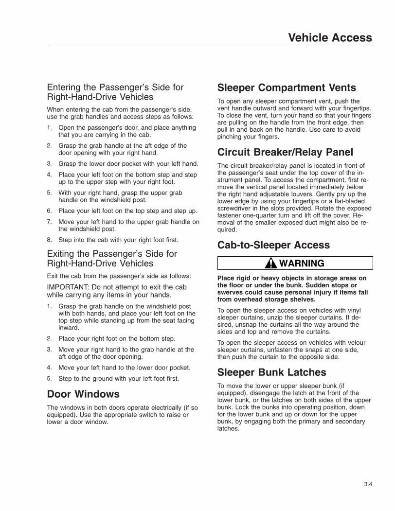
Entering the Passenger’s Side forRight-Hand-Drive VehiclesWhen entering the cab from the passenger’s side,use the grab handles and access steps as follows:
1. Open the passenger’s door, and place anythingthat you are carrying in the cab.
2. Grasp the grab handle at the aft edge of thedoor opening with your right hand.
3. Grasp the lower door pocket with your left hand.
4. Place your left foot on the bottom step and stepup to the upper step with your right foot.
5. With your right hand, grasp the upper grabhandle on the windshield post.
6. Place your left foot on the top step and step up.
7. Move your left hand to the upper grab handle onthe windshield post.
8. Step into the cab with your right foot first.
Exiting the Passenger’s Side forRight-Hand-Drive VehiclesExit the cab from the passenger’s side as follows:
IMPORTANT: Do not attempt to exit the cabwhile carrying any items in your hands.
1. Grasp the grab handle on the windshield postwith both hands, and place your left foot on thetop step while standing up from the seat facinginward.
2. Place your right foot on the bottom step.
3. Move your right hand to the grab handle at theaft edge of the door opening.
4. Move your left hand to the lower door pocket.
5. Step to the ground with your left foot first.
Door WindowsThe windows in both doors operate electrically (if soequipped). Use the appropriate switch to raise orlower a door window.
Sleeper Compartment VentsTo open any sleeper compartment vent, push thevent handle outward and forward with your fingertips.To close the vent, turn your hand so that your fingersare pulling on the handle from the front edge, thenpull in and back on the handle. Use care to avoidpinching your fingers.
Circuit Breaker/Relay PanelThe circuit breaker/relay panel is located in front ofthe passenger’s seat under the top cover of the in-strument panel. To access the compartment, first re-move the vertical panel located immediately belowthe right hand adjustable louvers. Gently pry up thelower edge by using your fingertips or a flat-bladedscrewdriver in the slots provided. Rotate the exposedfastener one-quarter turn and lift off the cover. Re-moval of the smaller exposed duct might also be re-quired.
Cab-to-Sleeper Access
WARNINGPlace rigid or heavy objects in storage areas onthe floor or under the bunk. Sudden stops orswerves could cause personal injury if items fallfrom overhead storage shelves.
To open the sleeper access on vehicles with vinylsleeper curtains, unzip the sleeper curtains. If de-sired, unsnap the curtains all the way around thesides and top and remove the curtains.
To open the sleeper access on vehicles with veloursleeper curtains, unfasten the snaps at one side,then push the curtain to the opposite side.
Sleeper Bunk LatchesTo move the lower or upper sleeper bunk (ifequipped), disengage the latch at the front of thelower bunk, or the latches on both sides of the upperbunk. Lock the bunks into operating position, downfor the lower bunk and up or down for the upperbunk, by engaging both the primary and secondarylatches.
Vehicle Access
3.4

Sleeper DoorThe sleeper door (Fig. 3.6, Ref. 1) is not intended forentry or exit. The door is intended only as a conve-nient means to stow or remove personal belongingsin and from the sleeper area. To open the door, pushdown on the lever handle located inside the sleepercompartment to the right of the door. The door canbe opened from the outside by pulling the releasecable strap inside the baggage door opening. Toclose the door, push it closed until it latches.
IMPORTANT: The sleeper doors are two-stagelatching. When closing the doors, ensure thatthey are completely latched to prevent windnoise and water intrusion.
Baggage Compartment DoorsTo unlock the baggage compartment door on thepassenger’s side, insert the ignition key in the lock-set, and turn it one-quarter turn clockwise. SeeFig. 3.6. Turn the key to the original position to re-move it. Pull up and outward on the baggage doorhandle to open the door. To close the door, push itclosed until it latches. To lock the door, insert the ig-nition key in the lockset and turn it one-quarter turncounterclockwise.
Use the same procedure to open the baggage com-partment door on the driver’s side, but turn the keycounterclockwise to unlock the door and clockwise tolock it.
Back-of-Cab Grab Handles,Steps, and Deck PlateWhen trailer connections cannot be reached conve-niently from the ground, Federal Motor Carrier SafetyAdministration Regulations require secure back-of-cab access supports.
Grab handles are mounted where they can providehand support, to maintain three points of hand-and-foot contact with the vehicle. See Fig. 3.7. Steps aremounted on the fuel tank, battery box, or frame, de-pending on the available space. When a deck plateis necessary, it is mounted across the top of theframe rails.
02/12/96 f601031
1
2
1. Sleeper Door2. Baggage Compartment Door
Fig. 3.6, Passenger-Side Sleeper and BaggageCompartment Doors
09/24/2007 f602335
2
1
1
3
1. Steps2. Grab Handle
3. Deck Plates
Fig. 3.7, Back-of-Cab Access (typical)
Vehicle Access
3.5
WARNINGWet or dirty shoe soles greatly increase thechance of slipping or falling. If your soles are wetor dirty, be especially careful when climbingonto, or down from, the back-of-cab area.
Always maintain three-point contact with theback-of-cab access supports while entering andexiting the back-of-cab area. Three-point contactmeans both feet and one hand, or both handsand one foot, on the grab handles, steps, anddeck plates. Other areas are not meant to sup-port back-of-cab access, and grabbing or step-ping in the wrong place could lead to a fall, andpersonal injury.
Be careful not to get hands or feet tangled inhoses or other back-of-cab equipment. Careless-ness could cause a person to trip and fall, withpossible injury.
Back-of-Cab Access Points (typical)When climbing onto the deck plate, use the grabhandle and access steps as follows:
1. Grasp the grab handle with both hands. Reachup as far as is comfortable.
IMPORTANT: Climb onto, and down from, back-of-cab access facing in toward the vehicle, asyou would on a ladder. Do not climb up or downfacing out away from the vehicle.
2. Place one foot on the bottom step and pull your-self up.
3. Place your other foot on the top step.
4. Move your lower hand to a higher position on thegrab handle.
5. Step onto the deck plate.
Exiting Back-of-CabWhen climbing down from the deck plate, use thegrab handle and access steps as follows:
1. Grasp the grab handle with both hands.
2. Step onto the top step.
3. Move your upper hand to a lower position on thegrab handle.
4. Move one foot to the bottom step.
5. Move your upper hand to a lower position on thegrab handle.
6. Step to the ground with your upper foot first.
Battery Box CoverTo remove the cover from the frame rail-mountedbattery box, release the latches that attach the leftchassis fairing panel (if equipped) in front of the bat-tery box. Remove the air fairing panel. See Group60 of the Century Class Trucks Workshop Manual forinstructions. If no air fairing panel is installed, removethe step plate. Pull on the end of each hold-downlatch until the end clears the cover-mounted catch.Pivot the latches out of the way, then lift off thecover. When installing the cover, be sure it is posi-tioned properly before fastening the latches.
To remove the cover from the battery box mountedbetween the frame rails, remove the deck plate andlift the handle on the top of the battery box cover. Ifequipped, remove the spring pin.
Hood TiltingThe hood can be tilted to a full-open position. A grabhandle at the front of the hood provides a hand-holdfor hood tilting. A torsion bar helps you to tilt thehood open, and to return it to the operating position.Hood straps prevent the hood from overtravel. In theoperating position, the hood is secured to the lowercab side panels by a hold-down latch on each side ofthe hood.
To Tilt the Hood1. Apply the parking brakes.
2. Release both hood hold-down latches by pullingthe ends outward.
CAUTIONDo not let the hood free-fall to the full-open posi-tion. To do so could cause damage to the hoodor hood straps.
3. Using the bumper step and grab handle, slowlytilt the hood until the straps support it. SeeFig. 3.8.
Vehicle Access
3.6
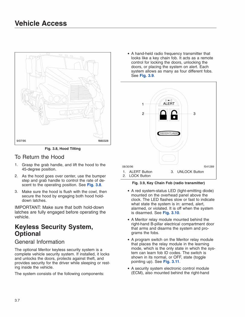
To Return the Hood1. Grasp the grab handle, and lift the hood to the
45-degree position.
2. As the hood goes over center, use the bumperstep and grab handle to control the rate of de-scent to the operating position. See Fig. 3.8.
3. Make sure the hood is flush with the cowl, thensecure the hood by engaging both hood hold-down latches.
IMPORTANT: Make sure that both hold-downlatches are fully engaged before operating thevehicle.
Keyless Security System,OptionalGeneral InformationThe optional Meritor keyless security system is acomplete vehicle security system. If installed, it locksand unlocks the doors, protects against theft, andprovides security for the driver while sleeping or rest-ing inside the vehicle.
The system consists of the following components:
• A hand-held radio frequency transmitter thatlooks like a key chain fob. It acts as a remotecontrol for locking the doors, unlocking thedoors, or placing the system on alert. Eachsystem allows as many as four different fobs.See Fig. 3.9.
• A red system-status LED (light-emitting diode)mounted on the overhead panel above theclock. The LED flashes slow or fast to indicatewhat state the system is in: armed, alert,alarmed, or violated. It is off when the systemis disarmed. See Fig. 3.10.
• A Meritor relay module mounted behind theright-hand B-pillar electrical compartment doorthat arms and disarms the system and pro-grams the fobs.
• A program switch on the Meritor relay modulethat places the relay module in the learningmode, which is the only state in which the sys-tem can learn fob ID codes. The switch isshown in its normal, or OFF, state (togglepointing up). See Fig. 3.11.
• A security system electronic control module(ECM), also mounted behind the right-hand
9/07/95 f880328
Fig. 3.8, Hood Tilting
08/30/96 f541289
ALERT1
2 3
1. ALERT Button2. LOCK Button
3. UNLOCK Button
Fig. 3.9, Key Chain Fob (radio transmitter)
Vehicle Access
3.7

B-pillar electrical compartment door, that moni-tors all the entry points, controls the doorlocks, operates the alarm, and interrupts thepower to the engine, as necessary. There isalso a PDM (power distribution module) relaymodule mounted on top of the left-hand side ofthe ECM.
How It WorksThe fob has three push buttons: LOCK, UNLOCK,and ALERT. When a button is pushed, the fob sendsa radio frequency signal to the ECM. The signal con-tains a unique vehicle access code that identifies theindividual fob, plus codes that indicate which buttonhas been pushed.
The ECM detects the signal sent by the fob, ampli-fies it, and converts it to a digital sequence.
If the LOCK button is pressed, the ECM arms thesystem. It locks the two cab doors, begins to monitorall the entry points (the two cab doors, the sleepercab access door, and the two baggage doors, as in-stalled), and instructs the relay module to start flash-ing the system LED at the slow rate. If any entrypoints are open, the ECM sounds the horn andflashes the cab marker lights twice. If the ignitionkeyswitch is turned off, the ECM interrupts ignitionpower to the engine.
The driver may be inside or outside the vehicle.However, if the engine is running at the time theLOCK button is pressed, the system still enters thearmed state, except that the engine is not immobi-lized. This improves security for the occupant as wellas comfort while sleeping or resting, because thesystem is armed, and the heating or air conditioningis operating without draining any batteries.
Once the system is armed, the alarm functions acti-vate whenever one of the entry points is opened. Inthe alarmed state, the ECM does the following:
• Immobilizes the vehicle by cutting off powerbetween the ignition keyswitch and the engineelectronic control unit (ECU).
• Sounds the horn in pulses of 0.5 second on,0.5 second off.
• Flashes the cab marker lights in pulses of 0.5second on, 0.5 second off.
• Changes the blink rate of the LED from slow tofast.
If the UNLOCK button is pressed, the ECM disarmsthe system, if armed. It unlocks all the entry points,discontinues its monitoring of the entry points, in-structs the relay module to stop flashing the systemLED, and restores ignition power to the engine, if in-terrupted.
®
SECURITY SYSTEM
07/01/96 f541288
1
2
3
1. System Status LED2. Overhead Panel
3. Clock
Fig. 3.10, Red System-Status LED
10/09/98 f541501a
Fig. 3.11, Program Switch
Vehicle Access
3.8

If the ALERT button is pressed, the ECM executesthe unlock sequence and also activates the vehiclealarm functions (see above). To cancel an ALERT (toturn off the alarm), press the UNLOCK button.
Once activated, the alarm sequence continues for 30seconds unless deactivated by pressing the UN-LOCK button on the fob. After 30 seconds in thealarmed state, the system automatically enters theviolated state.
In the violated state, the horn does not sound andthe cab marker lights do not flash, but the engine isstill immobilized and the LED continues to blink atthe fast rate. The vehicle remains in this state untilthe UNLOCK button is pressed.
Fob ProgrammingThe security system ECM can store up to four fobidentification codes. Once the first fob has been pro-grammed, there are never any vacant memory loca-tions.
IMPORTANT: As a security measure, all fobsmust be coded during the same programmingsequence. The first fob code is stored in all fourmemory locations. Taken together, these ensurethat only the vehicle owner’s fobs can be pro-grammed into the system. If additional fobs areprogrammed, they overwrite the original code inlocations two, three, and four, in that order.
The ECM provides a 20-second time period to pro-gram each fob. If the fob is not programmed withinthis time span, the system will exit the programmingsequence.
After each valid code storage sequence, the systemLED will indicate the completion of a learning cycleby turning off the LED for approximately 0.5 second,and unlocking the doors.
To program a fob, do the following steps:
1. With the ignition keyswitch turned off, turn theprogram switch ON (flip the toggle DOWN). SeeFig. 3.11.
2. Now turn the ignition keyswitch on. Note that thesystem LED illuminates continuously. SeeFig. 3.10. This indicates that the ECM is ready tobegin the learning sequence.
NOTE: If the LED does not illuminate continu-ously at this point, repeat the first two steps.
3. On the fob, press down both the LOCK and UN-LOCK buttons at the same time and hold themdown for at least three seconds. See Fig. 3.9. Ifthe code was learned, the system LED flashesand the doors unlock.
IMPORTANT: If no valid code was received, thesystem does not erase any stored data in thatmemory location. This is a security measure toensure that a fob ID cannot be erased acciden-tally.
4. Repeat the above step to program additionalfobs, up to a total of four.
5. When the programming sequence is over, returnthe system to normal operation by turning theprogram switch OFF (flip the toggle UP).
Fob Battery Replacement1. Open the battery cover on the back of the fob
with a suitable coin or other thin piece of metal.Twist off the cover. See Fig. 3.12.
2. Remove the battery and the O-ring installed in-side the cover. Save the O-ring for later installa-tion.
IMPORTANT: The battery may contain perchlo-rate material; special handling may apply, seewww.dtsc.ca.gov/hazardouswaste/perchlorate.
3. Install the new battery, as follows.
10/22/96
12
3
4
f541446
1. Fob2. Battery
3. O-Ring4. Battery Cover
Fig. 3.12, Fob Battery
Vehicle Access
3.9

3.1 Insert the new battery into the fob. Makesure the battery is right side up.
3.2 Install the O-ring as removed. If the O-ringis damaged, or there are signs of moistureinside the fob, replace the O-ring.
3.3 Twist on the battery cover and check it tomake sure it is tight.
4. Check the fob for correct operation.
Cab AmenitiesWaste BinTo remove the waste bin, slide the waste bin out asfar as it will go. Reach in behind the bin and releasethe bin from the stops on the bin sides. Remove thebin. See Fig. 3.13.
To install the bin, insert the bin onto the slides, andthen slide the bin into place.
Cup HoldersThe Century Class vehicle features two cup holders.The driver’s cup holder is located to the right of theash tray on the lower dash panel. The cup holderflips open for use, and can be pivoted into the dashwhen not needed. See Fig. 3.14. The passenger’scup holder pivots out of the lower dash console. SeeFig. 3.15. The passenger’s cup holder can also bepivoted into the console when not in use.
Ash Tray and Cigar LighterThe driver’s ash tray and cigar lighter assembly is onthe left side of the top of the lower dash panel. SeeFig. 3.16. There is a hinged cover that pivots back-ward to allow access to the cigar lighter and to theash tray. The tray is removable.
Dash Storage BinThe dash storage bin is located next to the driver’scup holder on the lower dash panel. See Fig. 3.17.The bin has a hinged cover, and can be used tostore sunglasses.
06/18/96 f601165
Fig. 3.13, Waste Bin
f601240a10/09/98
Fig. 3.14, Driver’s Cup Holder
f601241
1
10/15/96
2
1. Lower B-Panel Dash Assembly2. Passenger’s Cup Holder
Fig. 3.15, Passenger’s Cup Holder
Vehicle Access
3.10

Map HolderAn elastic-topped pouch is located above each door.These are intended for holding maps and otheritems.
Glove BoxSome vehicles have two glove boxes and two smalloverhead bins, all located in the overhead consoleassembly. See Fig. 3.18. Above the sun visors onboth the driver’s and the passenger’s sides are theglove boxes with latched doors or netted openings.In the middle section of the console assembly aretwo small bins. The driver’s-side bin is often removed
and replaced with a CB radio. The grille underneaththis portion of the console allows the radio’s speakerto be heard.
Overhead LightsAbove both the driver’s and the passenger’s seatsare three oval-shaped lights mounted to the bottomof the overhead console: a red light and two whitelights. The red light is mounted nearest to the wind-shield. Each light is activated by pushing on the lenscover. Also, the center light, a white light, activateswhen the doors to the vehicle are opened.
Footwell LightsThere are optional red lights mounted underneath thedash on the driver’s and the passenger’s sides of thevehicle. These lights are activated by a rocker switchon the lower dash panel next to the climate controlswitches.
Windshield Washer ReservoirThe windshield washer reservoir is located on theleft-hand side of the frontwall between the surge tankand the hood. See Fig. 3.19.
f601242
1
2
3
11/12/96
4
1. Ash Tray2. Cigar Lighter
3. Hinged Cover4. Driver’s Cup Holder
Fig. 3.16, Ash Tray and Cigar Lighter
f601243
1
10/15/96
2
1. Dash Storage Bin Cover2. Driver’s Cup Holder
Fig. 3.17, Dash Storage Bin
f60124410/15/96
1 2 3 4
1. Driver’s Glove Box2. Driver’s Overhead Storage Bin3. Passenger’s Overhead Storage Bin4. Passenger’s Glove Box
Fig. 3.18, Glove Boxes and Overhead Storage
Vehicle Access
3.11

1
2
3
f82019001/15/97
1. Surge Tank2. Washer Reservoir
3. Drain
Fig. 3.19, Windshield Washer Reservoir
Vehicle Access
3.12

4
Heater and Air ConditionerBlend Air Heater and Air Conditioner System . . . . . . . . . . . . . . . . . . . . . . . . . . . . . . . . . . . . . . . . . . . 4.1Water-Valve-Controlled Heater and Air Conditioner System . . . . . . . . . . . . . . . . . . . . . . . . . . . . . . . 4.4Parked HVAC . . . . . . . . . . . . . . . . . . . . . . . . . . . . . . . . . . . . . . . . . . . . . . . . . . . . . . . . . . . . . . . . . . . . 4.8

Blend Air Heater and AirConditioner SystemConstant Discharge TemperatureControlThe cab heater and air conditioner system is a Con-stant Discharge Temperature Control (CDTC) sys-tem. The CDTC maintains a constant temperature ofairflow in the cab regardless of outside air tempera-ture, selected fan speed, engine coolant temperature,or engine coolant flow. Once the temperature controlswitch is turned to the desired temperature, no otheradjustments are necessary. The CDTC system is dis-abled when the temperature control switch is in themaximum cool or maximum warm position.
Cab Climate Control PanelThe climate control panel allows you to control theheating and air conditioning functions of the heaterand air conditioner. See Fig. 4.1.
Fan SwitchThe fan switch controls the fan speed and forcesfresh air or recirculated air through the selected airoutlets. The fan switch has eight fan speeds and anoff position.
To increase airflow, turn the switch clockwise or to ahigher number. To decrease the airflow, turn theswitch counterclockwise or to a lower number. Set-ting the fan switch to the off position disables the airconditioner and places the air source in the fresh airmode.
NOTE: When the fan switch on the cab climatecontrol panel is off and the sleeper air condi-tioner is on, the cab fan will operate at lowspeed even though the cab fan switch is in theoff position. This is necessary to protect theevaporator in the cab heater and air conditionersystem from freezing.
There is a two-second delay between the time theengine is started and the blower is operational. It cantake an additional four seconds for the blower toreach high speed. The blower motor performs a self-test immediately after the engine is started, whichcauses the delay.
Air Selection SwitchThe air selection switch allows you to control the flowof air through the face outlets, the floor outlets, thedefrost (windshield) outlets, or a combination ofthese outlets to give you nine air selection modes.See Fig. 4.2.
1. Face Mode: Directs all airflow through the faceor instrument panel outlets.
2. Selection between Face Mode and Bi-LevelMode: Directs 75 percent of the airflow through
06/21/2001 f610450
1
2
3
4OBUNKOVRD
1
23
4
5
6
1. Bunk Override Switch2. Fan Switch
3. Recirculation Button4. Air Selection Switch
5. Air Conditioning Button6. Temperature Control Switch
Fig. 4.1, CDTC Climate Control Panel
Heater and Air Conditioner
4.1

the face outlets and 25 percent through the flooroutlets.
3. Bi-Level Mode: Directs the airflow equally to theface outlets and floor outlets.
4. Selection between Bi-Level Mode and FloorMode: Directs 25 percent of the airflow throughthe face outlets and 75 percent through the flooroutlets.
5. Floor Mode: Directs all airflow through the flooroutlets.
6. Selection between Floor Mode and Floor/Defog Mode: Directs 75 percent of the airflowthrough the floor outlets and 25 percent throughthe defrost outlets.
7. Defog Mode: Directs the airflow equally to thefloor outlets and the defrost outlets. The air con-ditioner automatically turns on in this mode. Therecirculation button will not work in this mode.
8. Selection between Defog Mode and DefrostMode: Directs 75 percent of the airflow throughthe defrost outlets and 25 percent through the
floor outlets. The air conditioner automaticallyturns on in this mode. The recirculation buttonwill not work in this mode.
9. Defrost Mode: Directs all airflow through thedefrost outlets. The air conditioner automaticallyturns on in this mode. The recirculation buttonwill not work in this mode.
Temperature Control SwitchThe temperature control switch is used to select thedesired temperature. On the manual and CDTC cli-mate control panel, turn the switch clockwise or tothe red area for warm air. Turn the switch counter-clockwise or to the blue area for cool air.
Air ConditioningThe air conditioner cools and dehumidifies the airinside the cab. Press the air conditioning button toturn the air conditioner on and off. See Fig. 4.3.
When the air conditioner is operating, the amber indi-cator on the air conditioning button will be onwhether the request for air conditioning comes fromthe cab climate control panel or the sleeper climatecontrol panel. When the instrument panel lights areon, the snowflake indicator on the air conditioningbutton will be on.
The air conditioner will be automatically disabledwhen:
• The outside air temperature is low enough tomake air conditioning ineffective;
• The engine is running at low rpm;
06/21/2001 f610502
1
2
3
45
6
7
8
9
1. Face Mode2. Selection Between Face Mode and Bi-Level Mode3. Bi-Level Mode4. Selection Between Bi-Level Mode and Floor Mode5. Floor Mode6. Selection Between Floor Mode and Floor/Defog
Mode7. Defog Mode8. Selection Between Defog Mode and Defrost Mode9. Defrost Mode
Fig. 4.2, Air Selection Switch Modes
06/21/2001 f610505
1
1. Amber Indicator
Fig. 4.3, Air Conditioning Button
Heater and Air Conditioner
4.2

• Specific conditions exist that result in theheater and air conditioner system going intoprotection mode.
RecirculationThe recirculation mode limits the amount of outsideair entering the cab. Press the recirculation button toprevent dusty or smoky air from entering the cab.See Fig. 4.4. The recirculation mode can also de-crease the time required to cool or heat the cab inte-rior during extreme outside temperature conditions.When the recirculation mode is on, the amber indica-tor on the recirculation button will be on.
The recirculation button will not work when the airselection switch is in one of the following modes:
• defog mode
• the selection between defog mode and defrostmode
• defrost mode
NOTE: To prevent the buildup of fumes or odorsand to prevent oxygen depletion inside the cab,the system switches from full recirculation modeto partial recirculation mode after 20 minutes. Inextremely dusty or smoky conditions, the partialrecirculation mode can be overridden by press-ing the recirculation button twice to obtain fullrecirculation mode. This resets the 20-minutetimer.
Bunk Override Switch, OptionalThe bunk override (BUNK OVRD) switch allows thedriver to remotely control the fan speed and tempera-
ture settings in the sleeper. See Fig. 4.1. Press theupper half of the bunk override switch to override thesleeper settings with the cab settings. The amberindicator on the switch is on when the bunk overridemode is on. If the fan speed or temperature settingon the sleeper climate control panel is adjusted whenthe bunk override mode is on, the bunk overridemode will be canceled.
When the heating and air conditioning system is inthe bunk override mode, the cab climate controlpanel can be adjusted without affecting the sleepersettings. To reset the sleeper settings, set the fanspeed and temperature settings on the cab climatecontrol panel to the desired sleeper settings andpress the upper half of the bunk override switchagain. The cab climate control panel can again beadjusted without affecting the sleeper settings.
Press the lower half of the bunk override switch tocancel the override mode. After the override mode iscanceled, the sleeper heater and air conditioner sys-tem will operate from the sleeper fan speed and tem-perature settings and the amber indicator will be off.
Sleeper Climate Control PanelThe sleeper heater and air conditioner system fea-tures Constant Discharge Temperature Control(CDTC). The sleeper climate control panel is shownin Fig. 4.5. The CDTC maintains a constant tempera-ture of airflow in the sleeper regardless of outside airtemperature, selected fan speed, engine coolant tem-perature, or engine coolant flow. Once the tempera-ture control switch is turned to the desired tempera-ture, no other adjustments are necessary.
Fan SwitchThe fan switch controls the sleeper heater and airconditioner system fan speed. The sleeper climatecontrol panel has eight fan speeds and an off posi-tion. To increase airflow, turn the switch clockwise orto a higher number. To decrease the airflow, turn theswitch counterclockwise or to a lower number.
NOTE: When the cab air conditioner is on, thesleeper fan will operate at low speed eventhough the sleeper fan switch is in the off posi-tion. This is necessary to protect the evaporatorin the sleeper heater and air conditioner systemfrom freezing.
06/21/2001 f610504
1
1. Amber Indicator
Fig. 4.4, Recirculation Button
Heater and Air Conditioner
4.3
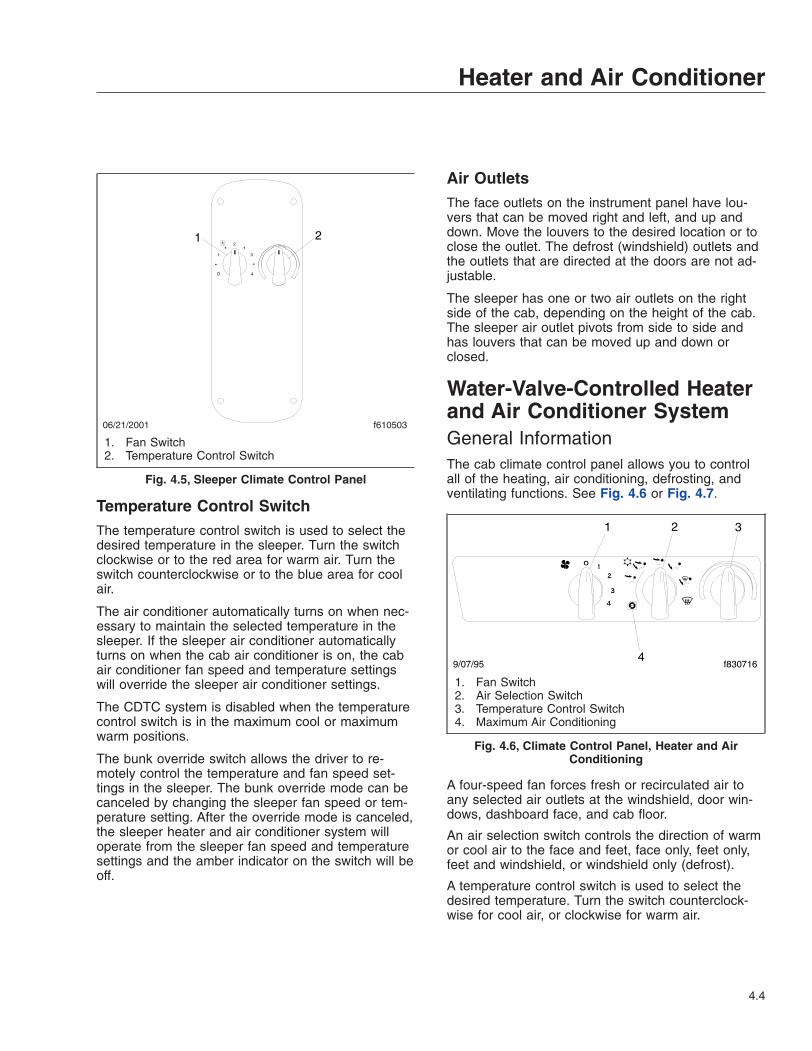
Temperature Control SwitchThe temperature control switch is used to select thedesired temperature in the sleeper. Turn the switchclockwise or to the red area for warm air. Turn theswitch counterclockwise or to the blue area for coolair.
The air conditioner automatically turns on when nec-essary to maintain the selected temperature in thesleeper. If the sleeper air conditioner automaticallyturns on when the cab air conditioner is on, the cabair conditioner fan speed and temperature settingswill override the sleeper air conditioner settings.
The CDTC system is disabled when the temperaturecontrol switch is in the maximum cool or maximumwarm positions.
The bunk override switch allows the driver to re-motely control the temperature and fan speed set-tings in the sleeper. The bunk override mode can becanceled by changing the sleeper fan speed or tem-perature setting. After the override mode is canceled,the sleeper heater and air conditioner system willoperate from the sleeper fan speed and temperaturesettings and the amber indicator on the switch will beoff.
Air OutletsThe face outlets on the instrument panel have lou-vers that can be moved right and left, and up anddown. Move the louvers to the desired location or toclose the outlet. The defrost (windshield) outlets andthe outlets that are directed at the doors are not ad-justable.
The sleeper has one or two air outlets on the rightside of the cab, depending on the height of the cab.The sleeper air outlet pivots from side to side andhas louvers that can be moved up and down orclosed.
Water-Valve-Controlled Heaterand Air Conditioner SystemGeneral InformationThe cab climate control panel allows you to controlall of the heating, air conditioning, defrosting, andventilating functions. See Fig. 4.6 or Fig. 4.7.
A four-speed fan forces fresh or recirculated air toany selected air outlets at the windshield, door win-dows, dashboard face, and cab floor.
An air selection switch controls the direction of warmor cool air to the face and feet, face only, feet only,feet and windshield, or windshield only (defrost).
A temperature control switch is used to select thedesired temperature. Turn the switch counterclock-wise for cool air, or clockwise for warm air.
06/21/2001 f610503
1
2
3
4O
1 2
1. Fan Switch2. Temperature Control Switch
Fig. 4.5, Sleeper Climate Control Panel
9/07/95 f830716
1 2 3
4
1. Fan Switch2. Air Selection Switch3. Temperature Control Switch4. Maximum Air Conditioning
Fig. 4.6, Climate Control Panel, Heater and AirConditioning
Heater and Air Conditioner
4.4

All of the dash-face outlets have adjustable louversthat pivot right, left, up, and down. The outlets canbe closed by moving the louvers all the way down.Windshield defrost outlets and the passenger’s doorwindow defrost outlet have nonadjustable louvers.The bunk outlet (at the right-hand rear corner of thebunk) has two sets of vertical louvers that operatelike the horizontal dash-face louvers.
The sleeper heater and air conditioner is installed inthe right-side baggage compartment and uses thecab’s refrigerant system for air conditioner operation.The sleeper heater and air conditioner is equippedwith a separate evaporator coil, expansion valve, andfan. It is also equipped with its own heater core andwater valve, independent of the cab heater. Thesleeper climate control panel is mounted on the rightrear wall or the rear overhead storage compartment.See Fig. 4.8.
NOTE: Shutting off the heater supply gate valve,if equipped, on the engine limits the ability tocontrol air conditioning temperature in the caband in the sleeper. With the valve shut off, warmcoolant is no longer available from the engineand the outlet air temperature controls can’t beused to change air temperature.
A fresh air/recirculation switch is standard equipmentwhen there is no air conditioning. See Fig. 4.7. Thiscontrol is an option when air conditioning is ordered.It allows the cab to be ventilated with either fresh orrecirculated air. When the air selection switch is ro-tated to the maximum air conditioning position, thesystem uses onlyrecirculated air, regardless of
whether fresh or recirculated air has been selected.See Fig. 4.6.
When the air selection switch is set to air condition-ing and recirculated air has been selected, the sys-tem functions the same as when the air selectionswitch is set at maximum air conditioning.
The fan bunk switch on the cab climate control paneloverrides the sleeper climate control panel. SeeFig. 4.7. For increased ventilation in the sleeper, putthe switch in the HI position. For normal fan and tem-perature operation, put the switch in the middle posi-tion. To turn the fan in the sleeper off, put the switchin the OFF position.
NOTE: When the bunk fan switch is in the OFFposition, the sleeper temperature control willdefault to the heat mode. The sleeper fan willblow hot air when any air conditioning mode isselected. To operate the temperature controls,move the bunk fan switch to the middle position.
A cab exhaust system is included with sleeper cabs.When the climate control unit is set for fresh air, 300cubic feet per minute of air is provided to the sleepercab and exhausted through a vent in the left reararea of the sleeper. When the system is activated,
10/26/95 f830717
1 2 3
45
1. Fan Switch2. Air Selection Switch3. Temperature Control Switch4. Fresh Air/Recirculation Switch5. Bunk Fan Switch
Fig. 4.7, Climate Control Panel, Heater Only
10/04/95 f830728
1
2
1. Temperature Control Switch2. Fan Switch
Fig. 4.8, Sleeper Climate Control Panel
Heater and Air Conditioner
4.5

fresh air rapidly displaces stale air as the cab pres-surizes.
IMPORTANT: To prevent the buildup of fumes orodors inside the cab (for example, from smok-ing), do not operate the heater and air condi-tioning system in a recirculation mode for morethan 20 minutes.
Defogging and Defrosting UsingFresh Air1. Turn the temperature control switch all the way
clockwise for warm air, the fan switch to off and,if equipped, the bunk fan switch to off beforestarting the engine.
2. Remove any ice or snow from the outside of thewindshield, door windows, and fresh air inletgrille.
3. With the engine at operating temperature, turnthe fan switch to 4, the highest speed. SeeFig. 4.9. Leave it in this position for 30 seconds.This will clear the system of moist air.
4. Move the air selection switch to the defrost(windshield) position. In this position warm, dryair is directed to the windshield.
NOTE: The air conditioner, if equipped, is auto-matically engaged in the defrost mode. Thisdries the air.
Heating1. With the engine at operating temperature, move
the temperature control switch all the way clock-wise for heat. See Fig. 4.10.
2. Turn on the fan switch to the desired speed.
3. Move the air selection switch to the desired set-ting.
IMPORTANT: If the windows start to fog, movethe air selection switch to defrost (windshield)and make sure the fan is on. To defog thedriver’s door window, turn the extreme left dash-face outlet to direct airflow to the upper left.
NOTE: In mild weather the fan switch can bekept off since forward motion of the vehicle willprovide airflow through the heater.
4. If the vehicle has a sleeper climate control panel,set the controls as desired. Refer to "Heating,Auxiliary Heater and Air Conditioner."
5. When a comfortable temperature has beenreached, adjust the fan switch setting and tem-perature control as needed to maintain the tem-perature.
IMPORTANT: To prevent the buildup of fumes orodors inside the cab (for example, from smok-ing), do not operate the heater and air condi-tioning system in a recirculation mode for morethan 20 minutes.
Air ConditioningIMPORTANT: Operate the air conditioner atleast five minutes each month, even during coolweather. This helps prevent drying and crackingof tubing seals, reducing refrigerant leaks in the
9/07/95 f830718
1 2 3
1. Fan Switch at Highest Speed2. Air Selection Switch at Defrost3. Temperature Control Switch at Warm
Fig. 4.9, Defogging and Defrosting Settings
9/07/95 f830719
1 2 3
4
1. Fan Switch2. Air Selection Switch3. Temperature Control Switch at Warm4. Fresh Air/Recirculation Switch
Fig. 4.10, Heating Settings
Heater and Air Conditioner
4.6
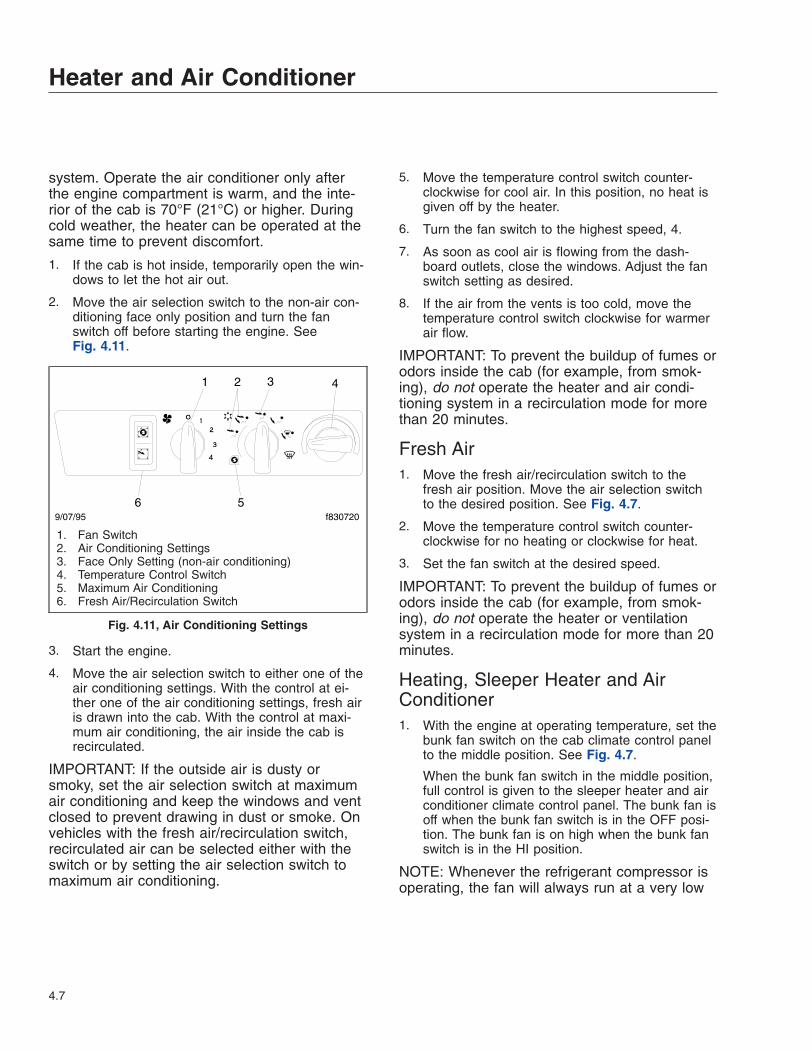
system. Operate the air conditioner only afterthe engine compartment is warm, and the inte-rior of the cab is 70°F (21°C) or higher. Duringcold weather, the heater can be operated at thesame time to prevent discomfort.
1. If the cab is hot inside, temporarily open the win-dows to let the hot air out.
2. Move the air selection switch to the non-air con-ditioning face only position and turn the fanswitch off before starting the engine. SeeFig. 4.11.
3. Start the engine.
4. Move the air selection switch to either one of theair conditioning settings. With the control at ei-ther one of the air conditioning settings, fresh airis drawn into the cab. With the control at maxi-mum air conditioning, the air inside the cab isrecirculated.
IMPORTANT: If the outside air is dusty orsmoky, set the air selection switch at maximumair conditioning and keep the windows and ventclosed to prevent drawing in dust or smoke. Onvehicles with the fresh air/recirculation switch,recirculated air can be selected either with theswitch or by setting the air selection switch tomaximum air conditioning.
5. Move the temperature control switch counter-clockwise for cool air. In this position, no heat isgiven off by the heater.
6. Turn the fan switch to the highest speed, 4.
7. As soon as cool air is flowing from the dash-board outlets, close the windows. Adjust the fanswitch setting as desired.
8. If the air from the vents is too cold, move thetemperature control switch clockwise for warmerair flow.
IMPORTANT: To prevent the buildup of fumes orodors inside the cab (for example, from smok-ing), do not operate the heater and air condi-tioning system in a recirculation mode for morethan 20 minutes.
Fresh Air1. Move the fresh air/recirculation switch to the
fresh air position. Move the air selection switchto the desired position. See Fig. 4.7.
2. Move the temperature control switch counter-clockwise for no heating or clockwise for heat.
3. Set the fan switch at the desired speed.
IMPORTANT: To prevent the buildup of fumes orodors inside the cab (for example, from smok-ing), do not operate the heater or ventilationsystem in a recirculation mode for more than 20minutes.
Heating, Sleeper Heater and AirConditioner1. With the engine at operating temperature, set the
bunk fan switch on the cab climate control panelto the middle position. See Fig. 4.7.
When the bunk fan switch in the middle position,full control is given to the sleeper heater and airconditioner climate control panel. The bunk fan isoff when the bunk fan switch is in the OFF posi-tion. The bunk fan is on high when the bunk fanswitch is in the HI position.
NOTE: Whenever the refrigerant compressor isoperating, the fan will always run at a very low
9/07/95 f830720
1 2 3 4
56
1. Fan Switch2. Air Conditioning Settings3. Face Only Setting (non-air conditioning)4. Temperature Control Switch5. Maximum Air Conditioning6. Fresh Air/Recirculation Switch
Fig. 4.11, Air Conditioning Settings
Heater and Air Conditioner
4.7
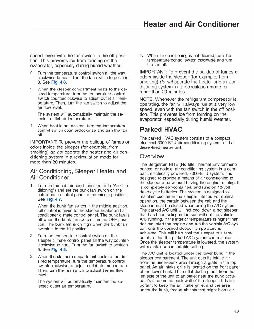
speed, even with the fan switch in the off posi-tion. This prevents ice from forming on theevaporator, especially during humid weather.
2. Turn the temperature control switch all the wayclockwise to heat. Turn the fan switch to position3. See Fig. 4.8.
3. When the sleeper compartment heats to the de-sired temperature, turn the temperature controlswitch counterclockwise to adjust outlet air tem-perature. Then, turn the fan switch to adjust theair flow level.
The system will automatically maintain the se-lected outlet air temperature.
4. When heat is not desired, turn the temperaturecontrol switch counterclockwise and turn the fanoff.
IMPORTANT: To prevent the buildup of fumes orodors inside the sleeper (for example, fromsmoking) do not operate the heater and air con-ditioning system in a recirculation mode formore than 20 minutes.
Air Conditioning, Sleeper Heater andAir Conditioner1. Turn on the cab air conditioner (refer to "Air Con-
ditioning") and set the bunk fan switch on thecab climate control panel to the middle position.See Fig. 4.7.
When the bunk fan switch in the middle position,full control is given to the sleeper heater and airconditioner climate control panel. The bunk fan isoff when the bunk fan switch is in the OFF posi-tion. The bunk fan is on high when the bunk fanswitch is in the HI position.
2. Turn the temperature control switch on thesleeper climate control panel all the way counter-clockwise to cool. Turn the fan switch to position3. See Fig. 4.8.
3. When the sleeper compartment cools to the de-sired temperature, turn the temperature controlswitch clockwise to adjust outlet air temperature.Then, turn the fan switch to adjust the air flowlevel.
The system will automatically maintain the se-lected outlet air temperature.
4. When air conditioning is not desired, turn thetemperature control switch clockwise and turnthe fan off.
IMPORTANT: To prevent the buildup of fumes orodors inside the sleeper (for example, fromsmoking) do not operate the heater and air con-ditioning system in a recirculation mode formore than 20 minutes.
NOTE: Whenever the refrigerant compressor isoperating, the fan will always run at a very lowspeed, even with the fan switch in the off posi-tion. This prevents ice from forming on theevaporator, especially during humid weather.
Parked HVACThe parked HVAC system consists of a compactelectrical 3000-BTU air conditioning system, and adiesel-fired heater unit.
OverviewThe Bergstrom NITE (No Idle Thermal Environment)parked, or no-idle, air conditioning system is a com-pact, electrically powered, 3000-BTU system. It isdesigned to provide a means of air conditioning tothe sleeper area without having the engine running. Itis completely self-contained, and runs on 12-voltdeep-cycle batteries. The system is designed tomaintain cool air in the sleeper interior. For optimaloperation, the curtain between the cab and thesleeper must be closed when using the A/C system.The parked A/C unit will not cool down a hot sleeperthat has been sitting in the sun without the vehicleA/C running. If the interior temperature is higher thandesired, start the engine and run the vehicle A/C sys-tem until the desired sleeper temperature isachieved. This will help cool the sleeper to a tem-perature that the parked A/C system can maintain.Once the sleeper temperature is lowered, the systemwill maintain a comfortable setting.
The A/C unit is located under the lower bunk in thesleeper compartment. The unit gets its intake airfrom the under-bunk area through a grate in the toppanel. An air intake grille is located on the front panelof the lower bunk. The outlet ducting runs from theleft side of the unit to an outlet near the bunk occu-pant’s face on the back wall of the sleeper. It is im-portant to keep the air intake grille, and the areaunder the bunk, free of objects that might block air
Heater and Air Conditioner
4.8
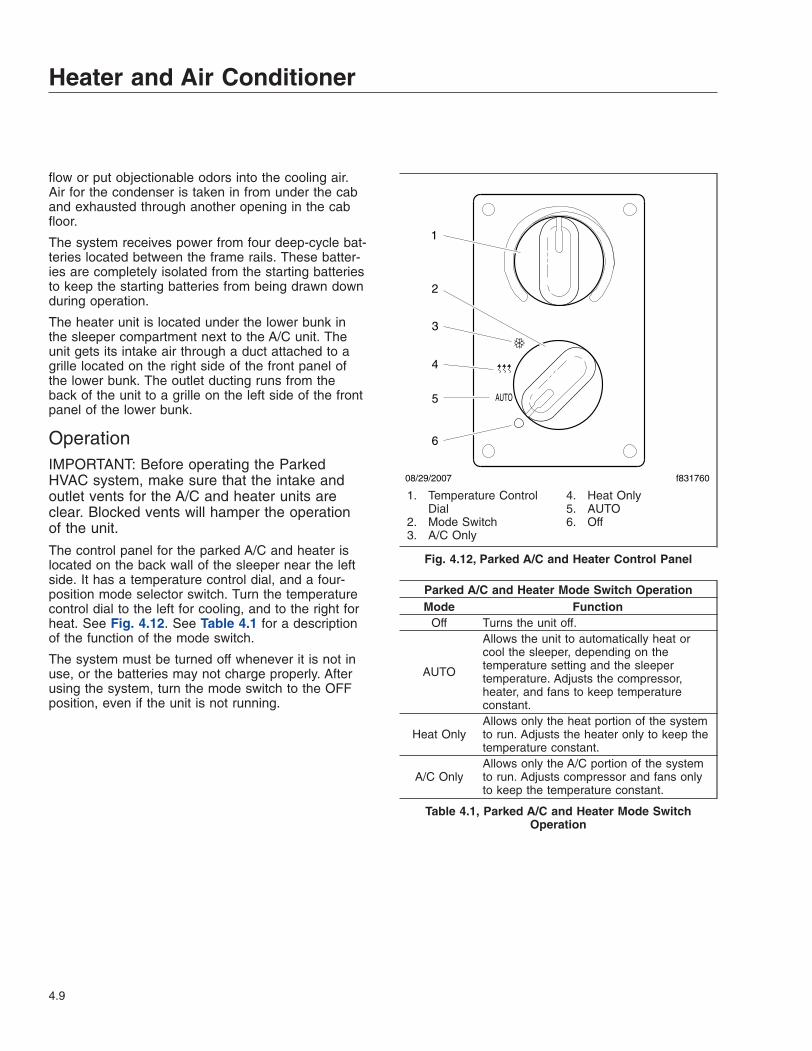
flow or put objectionable odors into the cooling air.Air for the condenser is taken in from under the caband exhausted through another opening in the cabfloor.
The system receives power from four deep-cycle bat-teries located between the frame rails. These batter-ies are completely isolated from the starting batteriesto keep the starting batteries from being drawn downduring operation.
The heater unit is located under the lower bunk inthe sleeper compartment next to the A/C unit. Theunit gets its intake air through a duct attached to agrille located on the right side of the front panel ofthe lower bunk. The outlet ducting runs from theback of the unit to a grille on the left side of the frontpanel of the lower bunk.
OperationIMPORTANT: Before operating the ParkedHVAC system, make sure that the intake andoutlet vents for the A/C and heater units areclear. Blocked vents will hamper the operationof the unit.
The control panel for the parked A/C and heater islocated on the back wall of the sleeper near the leftside. It has a temperature control dial, and a four-position mode selector switch. Turn the temperaturecontrol dial to the left for cooling, and to the right forheat. See Fig. 4.12. See Table 4.1 for a descriptionof the function of the mode switch.
The system must be turned off whenever it is not inuse, or the batteries may not charge properly. Afterusing the system, turn the mode switch to the OFFposition, even if the unit is not running.
Parked A/C and Heater Mode Switch OperationMode Function
Off Turns the unit off.
AUTO
Allows the unit to automatically heat orcool the sleeper, depending on thetemperature setting and the sleepertemperature. Adjusts the compressor,heater, and fans to keep temperatureconstant.
Heat OnlyAllows only the heat portion of the systemto run. Adjusts the heater only to keep thetemperature constant.
A/C OnlyAllows only the A/C portion of the systemto run. Adjusts compressor and fans onlyto keep the temperature constant.
Table 4.1, Parked A/C and Heater Mode SwitchOperation
AUTO
08/29/2007 f831760
1
2
3
4
5
6
1. Temperature ControlDial
2. Mode Switch3. A/C Only
4. Heat Only5. AUTO6. Off
Fig. 4.12, Parked A/C and Heater Control Panel
Heater and Air Conditioner
4.9

5
Seats and Seat BeltsSeats . . . . . . . . . . . . . . . . . . . . . . . . . . . . . . . . . . . . . . . . . . . . . . . . . . . . . . . . . . . . . . . . . . . . . . . . . . . 5.1Seat Belts and Tether Belts . . . . . . . . . . . . . . . . . . . . . . . . . . . . . . . . . . . . . . . . . . . . . . . . . . . . . . . . . 5.6Sleeper Compartment Restraints . . . . . . . . . . . . . . . . . . . . . . . . . . . . . . . . . . . . . . . . . . . . . . . . . . . . . 5.9Supplemental Restraint System, Optional . . . . . . . . . . . . . . . . . . . . . . . . . . . . . . . . . . . . . . . . . . . . . 5.10Air Bag, Optional . . . . . . . . . . . . . . . . . . . . . . . . . . . . . . . . . . . . . . . . . . . . . . . . . . . . . . . . . . . . . . . . 5.10SPACE System, Optional . . . . . . . . . . . . . . . . . . . . . . . . . . . . . . . . . . . . . . . . . . . . . . . . . . . . . . . . . . 5.11

SeatsGeneral InformationUnless otherwise noted, all seat adjustments shouldbe made while seated and before the engine isstarted.
Due to the maximum adjustability of mid- and high-back air suspension seats, it is possible to combinethe seat back recline adjustment and the seat slideadjustment so that the seat back contacts the back-wall. It is the responsibility of the driver to adjust theseat to prevent damage to the seat and the cab inte-rior.
WARNINGKeep hands, tools, and other objects away fromthe scissor points under the seats. Failure to doso could cause personal injury.
Seat AdjustmentsThe following is a description of adjustments that canbe made to various Freightliner-installed seats. Notall seats have all of the adjustments listed below.See Fig. 5.1.
1. Back Cushion Tilt: This adjustment enables theback cushion to pivot forward or backward.
2. Lumbar Support: Lumbar support changes theshape of the seat back to give more or less sup-port to the occupant’s lumbar (lower back) area.This adjustment is either mechanical or air con-trolled, depending on make and model of theseat.
3. Isolator: This feature (also referred to as back-slap isolator or Chugger-Snubber®) reduces theamount of road shock by isolating the occupantfrom the motion of the vehicle, and allowing theupper seat to move in a simple pendulum mo-tion. A lockout feature is used whenever the iso-lator is not desired.
10/26/2000 f910149a
1
2
3 4
56 7
8
1. Back Cushion Tilt2. Lumbar Support3. Isolator Feature4. Height Adjustment
5. Bottom Cushion Angle (fore and aft cushion height)6. Fore and Aft Seat Adjustment (seat track adjustment)7. Seat Tilt8. Upper Back Cushion
Fig. 5.1, Seat Adjustments
Seats and Seat Belts
5.1

4. Height Adjustment: The entire seat moves up ordown when adjusting the height. The adjustmentis either manually or air controlled, depending onthe make of the seat.
5. Bottom Cushion Angle or Fore and Aft BottomCushion Height: This feature enables the occu-pant to raise or lower the front or back of thebottom cushion. This adjustment is easier to per-form when all weight is removed from the seat.
6. Fore and Aft Seat or Seat Track Adjustment: Theentire seat moves forward or backward when thisadjustment is made.
7. Seat Tilt: When this adjustment is made, the seatassembly (back and bottom cushions) tilts for-ward or backward.
8. Upper Back Cushion Adjustment: When this ad-justment is made, the upper back cushionchanges angle to provide upper back support.
9. Weight Adjustment: On those seats with weightadjustment, the feature is fully automatic. Whenyou sit on the seat, a leveling valve places you inthe center of the ride zone. Additional adjust-ments are possible by using the height adjust-ment feature.
EzyRider® SeatFor seat adjustment controls on vehicles built beforeNovember 28, 2005, see Fig. 5.2. For seat adjust-ment controls on vehicles built on or after November28, 2005, see Fig. 5.3.
Back Cushion TiltTo tilt the back cushion, raise the back cushion tiltlever and lean forward or backward. Release thelever to lock the cushion in place.
Lumbar SupportTo adjust the amount of support for your lower back,use the lumbar support switch or lever on the side ofthe seat.
IsolatorTo engage the isolator, push in on the isolator lever.To lock out the isolator, pull the isolator lever out tothe first stop.
Fore and Aft Seat AdjustmentPull the fore and aft seat adjustment lever out to thesecond stop and slide the seat forward or backwardto the desired position.
Height AdjustmentTo raise or lower the seat, use the height adjustmentswitch or lever on the side of the seat.
Bottom Cushion AngleTo adjust the bottom cushion angle, pull the bottomcushion up and forward or down and back. The bot-tom cushion angle is controlled by the guides oneach side of the seat.
Seat Position IndicatorsSeats installed in vehicles built before November 28,2005 are equipped with seat position indicators. Aback cushion tilt position indicator and a fore/aft seat
f9104561
2
3
4
5
6
03/12/20017
1. Isolator and Fore/Aft Seat Adjustment Lever2. Bottom Cushion Angle Guide3. Armrest Adjustment Knob4. Back Cushion Tilt Position Indicator5. Back Cushion Tilt Lever6. Height Adjustment and Lumbar Support Lever7. Fore/Aft Seat Position Indicator
Fig. 5.2, EzyRider Seat Adjustment Controls (VehiclesBuilt Before November 28, 2005)
Seats and Seat Belts
5.2
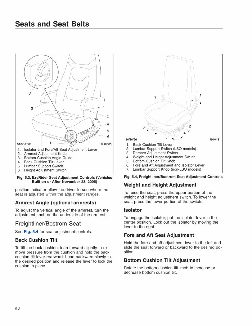
position indicator allow the driver to see where theseat is adjusted within the adjustment ranges.
Armrest Angle (optional armrests)To adjust the vertical angle of the armrest, turn theadjustment knob on the underside of the armrest.
Freightliner/Bostrom SeatSee Fig. 5.4 for seat adjustment controls.
Back Cushion TiltTo tilt the back cushion, lean forward slightly to re-move pressure from the cushion and hold the backcushion tilt lever rearward. Lean backward slowly tothe desired position and release the lever to lock thecushion in place.
Weight and Height AdjustmentTo raise the seat, press the upper portion of theweight and height adjustment switch. To lower theseat, press the lower portion of the switch.
IsolatorTo engage the isolator, put the isolator lever in thecenter position. Lock out the isolator by moving thelever to the right.
Fore and Aft Seat AdjustmentHold the fore and aft adjustment lever to the left andslide the seat forward or backward to the desired po-sition.
Bottom Cushion Tilt AdjustmentRotate the bottom cushion tilt knob to increase ordecrease bottom cushion tilt.
f9105651
3
4
5
6
2
2
01/06/2006
1. Isolator and Fore/Aft Seat Adjustment Lever2. Armrest Adjustment Knob3. Bottom Cushion Angle Guide4. Back Cushion Tilt Lever5. Lumbar Support Switch6. Height Adjustment Switch
Fig. 5.3, EzyRider Seat Adjustment Controls (VehiclesBuilt on or After November 28, 2005)
1
23
45
6
7
10/10/96 f910131
1. Back Cushion Tilt Lever2. Lumbar Support Switch (LSO models)3. Damper Adjustment Switch4. Weight and Height Adjustment Switch5. Bottom Cushion Tilt Knob6. Fore and Aft Adjustment and Isolator Lever7. Lumbar Support Knob (non-LSO models)
Fig. 5.4, Freightliner/Bostrom Seat Adjustment Controls
Seats and Seat Belts
5.3

Lumbar SupportTo increase lumbar support on LSO models, pressthe plus sign on the lumbar support switch. To de-crease lumbar support on LSO models, press theminus sign on the switch. To increase lumbar supporton non-LSO models, rotate the lumbar support knobforward. To decrease lumbar support on non-LSOmodels, rotate the knob rearward.
Damper AdjustmentPress the damper adjustment switch to adjust thedamper.
Dura-Form Fleetcruiser SeatSee Fig. 5.5 for seat adjustment controls.
Back Cushion TiltTo tilt the back cushion through a range of 10 de-grees, push down on the back cushion tilt handle.Move the back cushion to the desired position andrelease the handle.
Height AdjustmentPush the height adjustment knob in to inflate the sus-pension and raise the seat. Pull the knob out to de-flate the suspension and lower the seat.
Isolator and Fore-Aft Seat AdjustmentMove the fore-aft adjustment lever to the left to ad-just the seat to the desired fore-aft position. Movethe same lever to the center position to lock out theisolator feature. Move the lever to the right to engagethe isolator.
Seat Cushion AdjustmentTo put the seat cushion in the upper position, lift up-ward on the front of the cushion, then push rearward.To put the seat cushion in the lower position, pull for-ward and then push downward.
Lumbar SupportMove the lumbar support lever to any of the threepositions as desired.
National 2000 Series SeatSee Fig. 5.6 for seat adjustment controls.
Back Cushion TiltTo tilt the back cushion, turn the back cushion tiltknob until the desired position is reached.
Height AdjustmentTo raise or lower the height of the seat, use theheight adjustment switch on the side of the seat.
Fore and Aft Seat AdjustmentTo adjust the fore and aft position of the entire seat,move the fore and aft seat adjustment lever to theleft and slide the seat forward or backward to thedesired position. Move the lever back to its originalposition to lock the seat in place.
Rear Cushion AdjustmentTo adjust the height of the rear of the seat cushion,remove your weight from the seat and turn the rearcushion adjustment knob to one of three positions.
1
2
5
34
02/09/95 f910003a
1. Back Cushion Tilt Handle2. Height Adjustment Knob3. Isolator and Fore-Aft Adjustment Lever4. Seat Cushion Adjustment5. Lumbar Support Lever
Fig. 5.5, Dura-Form Fleetcruiser Seat AdjustmentControls
Seats and Seat Belts
5.4
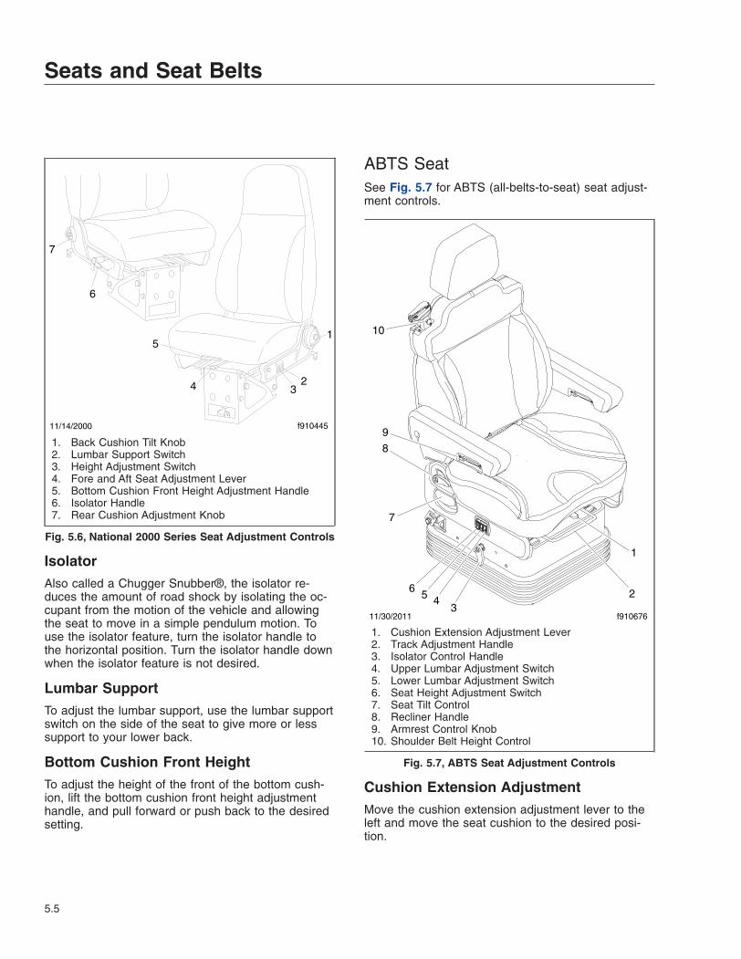
IsolatorAlso called a Chugger Snubber®, the isolator re-duces the amount of road shock by isolating the oc-cupant from the motion of the vehicle and allowingthe seat to move in a simple pendulum motion. Touse the isolator feature, turn the isolator handle tothe horizontal position. Turn the isolator handle downwhen the isolator feature is not desired.
Lumbar SupportTo adjust the lumbar support, use the lumbar supportswitch on the side of the seat to give more or lesssupport to your lower back.
Bottom Cushion Front HeightTo adjust the height of the front of the bottom cush-ion, lift the bottom cushion front height adjustmenthandle, and pull forward or push back to the desiredsetting.
ABTS SeatSee Fig. 5.7 for ABTS (all-belts-to-seat) seat adjust-ment controls.
Cushion Extension AdjustmentMove the cushion extension adjustment lever to theleft and move the seat cushion to the desired posi-tion.
11/14/2000
1
234
5
f910445
6
7
1. Back Cushion Tilt Knob2. Lumbar Support Switch3. Height Adjustment Switch4. Fore and Aft Seat Adjustment Lever5. Bottom Cushion Front Height Adjustment Handle6. Isolator Handle7. Rear Cushion Adjustment Knob
Fig. 5.6, National 2000 Series Seat Adjustment Controls
11/30/2011 f910676
1
23
456
7
8
9
10
1. Cushion Extension Adjustment Lever2. Track Adjustment Handle3. Isolator Control Handle4. Upper Lumbar Adjustment Switch5. Lower Lumbar Adjustment Switch6. Seat Height Adjustment Switch7. Seat Tilt Control8. Recliner Handle9. Armrest Control Knob10. Shoulder Belt Height Control
Fig. 5.7, ABTS Seat Adjustment Controls
Seats and Seat Belts
5.5

Track AdjustmentTo adjust the fore-and-aft position of the entire seat,lift the track adjustment handle and slide the seat tothe desired position.
IsolatorPull up the isolator control handle to lock out the iso-lation movement.
Lumbar AdjustmentPush the middle rocker switch to adjust the lowerlumbar bag. Push the forward switch to adjust theupper lumbar bag.
Seat Height AdjustmentPush the seat height adjustment switch to raise orlower the seat suspension.
Seat Tilt ControlSet the seat tilt control to one of the five positions toset cushion rake adjustment.
Backrest AdjustmentTo tilt the backrest backward, pull up on the reclinerhandle while leaning backward. To tilt the backrestforward, pull up on the recliner handle while leaningforward.
Armrest AdjustmentRotate the control knob, located on the underside ofthe armrest, to set the desired angle of the armrest.
Shoulder Belt Height ControlAdjust the shoulder belt height. The height can beadjusted vertically by 3 inches (75 mm).
Seat Belts and Tether BeltsGeneral InformationSeat belt assemblies are designed to secure personsin the vehicle to help reduce the chance of injury orthe amount of injury resulting from accidents or sud-den stops. For this reason, Daimler Trucks NorthAmerica LLC urges that the driver and all passen-gers, regardless of age or physical condition, useseat belts when riding in the vehicle.
WARNINGAlways use the vehicle’s seat belt system whenoperating the vehicle. Failure to do so can resultin severe personal injury or death.
Seat belt assemblies in Daimler Trucks NorthAmerica (DTNA) vehicles meet Federal Motor Ve-hicle Safety Standard 209, "Type 1" and "Type 2" re-quirements.
When transporting a child, always use a child re-straint system or the vehicle seat belts as appropri-ate. To determine whether a child restraint system isrequired, review and comply with applicable stateand local laws. Any child restraint used must complywith Federal Motor Vehicle Safety Standard 213,"Child Restraint Systems." When providing a childrestraint system, always carefully read and follow allinstructions pertaining to installation and usage forthe child. Make certain the child remains in the re-straint system at all times when the vehicle is in mo-tion.
In addition to seat belt assemblies, tether belts areinstalled on suspension-type seats. Tether belts helpsecure the seat to the floor and are intended to re-strain the seat and seat belt in case of an accident orsudden stop.
IMPORTANT: Seat belts have a finite life whichmay be much shorter than the life of the vehicle.Regular inspections and replacement as neededare the only assurance of adequate seat beltsecurity over the life of the vehicle.
Seat Belt Inspection
WARNINGInspect and maintain seat belts. When any part ofa seat belt system needs replacement, the entireseat belt must be replaced, both retractor andbuckle side. Any time a vehicle is involved in anaccident, and the seat belt system was in use,the entire vehicle seat belt system must be re-placed before operating the vehicle. Do not at-tempt to modify the seat belt system; doing socould change the effectiveness of the system.Failure to replace worn or damaged seat belts, ormaking any modifications to the system, may re-sult in personal injury or death.
Seats and Seat Belts
5.6
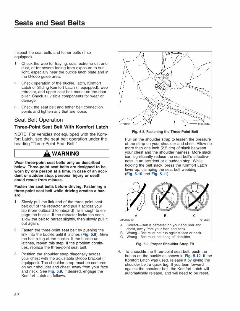
Inspect the seat belts and tether belts (if soequipped).
1. Check the web for fraying, cuts, extreme dirt anddust, or for severe fading from exposure to sun-light, especially near the buckle latch plate and inthe D-loop guide area.
2. Check operation of the buckle, latch, KomfortLatch or Sliding Komfort Latch (if equipped), webretractor, and upper seat belt mount on the doorpillar. Check all visible components for wear ordamage.
3. Check the seat belt and tether belt connectionpoints and tighten any that are loose.
Seat Belt OperationThree-Point Seat Belt With Komfort Latch
NOTE: For vehicles not equipped with the Kom-fort Latch, see the seat belt operation under theheading "Three-Point Seat Belt."
WARNINGWear three-point seat belts only as describedbelow. Three-point seat belts are designed to beworn by one person at a time. In case of an acci-dent or sudden stop, personal injury or deathcould result from misuse.
Fasten the seat belts before driving. Fastening athree-point seat belt while driving creates a haz-ard.
1. Slowly pull the link end of the three-point seatbelt out of the retractor and pull it across yourlap (from outboard to inboard) far enough to en-gage the buckle. If the retractor locks too soon,allow the belt to retract slightly, then slowly pull itout again.
2. Fasten the three-point seat belt by pushing thelink into the buckle until it latches (Fig. 5.8). Givethe belt a tug at the buckle. If the buckle un-latches, repeat this step. If the problem contin-ues, replace the three-point seat belt.
3. Position the shoulder strap diagonally acrossyour chest with the adjustable D-loop bracket (ifequipped). The shoulder strap must be centeredon your shoulder and chest, away from your faceand neck. See Fig. 5.9. If desired, engage theKomfort Latch as follows.
Pull on the shoulder strap to lessen the pressureof the strap on your shoulder and chest. Allow nomore than one inch (2.5 cm) of slack betweenyour chest and the shoulder harness. More slackcan significantly reduce the seat belt’s effective-ness in an accident or a sudden stop. Whileholding the belt slack, press the Komfort Latchlever up, clamping the seat belt webbing(Fig. 5.10 and Fig. 5.11).
4. To unbuckle the three-point seat belt, push thebutton on the buckle as shown in Fig. 5.12. If theKomfort Latch was used, release it by giving theshoulder belt a quick tug. If you lean forwardagainst the shoulder belt, the Komfort Latch willautomatically release, and will need to be reset.
01/18/95 f910004a
Fig. 5.8, Fastening the Three-Point Belt
08/09/2010 f910634A B C
A. Correct—Belt is centered on your shoulder andchest, away from your face and neck.
B. Wrong—Belt must not rub against face or neck.C. Wrong—Belt must not hang off shoulder.
Fig. 5.9, Proper Shoulder Strap Fit
Seats and Seat Belts
5.7

NOTE: The Komfort Latch does not have to bereleased in an emergency situation. The Kom-fort Latch will release by itself under rough roador other abnormal conditions. Make sure thethree-point seat belt is completely retractedwhen it is not in use.
Three-Point Seat Belt
NOTE: For vehicles equipped with the KomfortLatch, see the seat belt operation under theheading "Three-Point Seat Belt With KomfortLatch."
WARNINGWear three-point seat belts only as describedbelow. Three-point seat belts are designed to beworn by one person at a time. In case of an acci-dent or sudden stop, personal injury or deathcould result from misuse.
Fasten the seat belts before driving. Fastening athree-point seat belt while driving creates a haz-ard.
1. Slowly pull the link end of the three-point seatbelt out of the retractor and pull it across yourlap (from outboard to inboard) far enough to en-gage the buckle. If the retractor locks too soon,allow the belt to retract slightly, then slowly pull itout again.
2. Fasten the three-point seat belt by pushing thelatch into the buckle. Listen for an audible click.See Fig. 5.8.
3. Tug on the seat belt to make sure it is securelyfastened. If the buckle unlatches, repeat thisstep. If the problem continues, replace the three-point seat belt.
4. Snug the seat belt to your waist.
5. Position the shoulder strap diagonally acrossyour chest with the adjustable D-loop bracket (ifequipped). The shoulder strap must be centered
A
01/06/95 f910048a
A. 1 Inch (2.5 cm) Maximum
Fig. 5.10, Adjusting Shoulder Harness Clearance
11/02/95 f910144
Fig. 5.11, Locking Komfort Latch
01/18/95 f910049a
Fig. 5.12, Releasing the Three-Point Seat Belt
Seats and Seat Belts
5.8
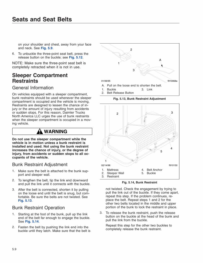
on your shoulder and chest, away from your faceand neck. See Fig. 5.9.
6. To unbuckle the three-point seat belt, press therelease button on the buckle; see Fig. 5.12.
NOTE: Make sure the three-point seat belt iscompletely retracted when it is not in use.
Sleeper CompartmentRestraintsGeneral InformationOn vehicles equipped with a sleeper compartment,bunk restraints should be used whenever the sleepercompartment is occupied and the vehicle is moving.Restraints are designed to lessen the chance of in-jury or the amount of injury resulting from accidentsor sudden stops. For this reason, Daimler TrucksNorth America LLC urges the use of bunk restraintswhen the sleeper compartment is occupied in a mov-ing vehicle.
WARNINGDo not use the sleeper compartment while thevehicle is in motion unless a bunk restraint isinstalled and used. Not using the bunk restraintincreases the chance of injury, or the degree ofinjury, from accidents or sudden stops to all oc-cupants of the vehicle.
Bunk Restraint Adjustment1. Make sure the belt is attached to the bunk sup-
port and sleeper wall.
2. To lengthen the belt, tip the link end downwardand pull the link until it connects with the buckle.
3. After the belt is connected, shorten it by pullingon the loose end until the belt is snug, but com-fortable. Be sure the belts are not twisted. SeeFig. 5.13.
Bunk Restraint Operation1. Starting at the foot of the bunk, pull up the link
end of the belt far enough to engage the buckle.See Fig. 5.14.
2. Fasten the belt by pushing the link end into thebuckle until they latch. Make sure that the belt is
not twisted. Check the engagement by trying topull the link out of the buckle. If they come apart,repeat this step. If the problem continues, re-place the belt. Repeat steps 1 and 2 for theother two belts located in the middle and upperportion of the bunk to lock the restraint in place.
3. To release the bunk restraint, push the releasebutton on the buckle at the head of the bunk andpull the link from the buckle.
Repeat this step for the other two buckles tocompletely release the bunk restraint.
1
2
3
A
01/06/95 f910068a
A. Pull on the loose end to shorten the belt.1. Buckle2. Belt Release Button
3. Link
Fig. 5.13, Bunk Restraint Adjustment
1
2
f91015002/14/96
3
45
1. Mattress2. Sleeper Wall3. Restraint
4. Belt Anchor5. Buckle
Fig. 5.14, Bunk Restraint
Seats and Seat Belts
5.9
Supplemental RestraintSystem, OptionalThe supplemental restraint system can consist of anair bag and SPACE system, or an air bag only sys-tem. Your vehicle may or may not have a supple-mental restraint system.
Air Bag, OptionalThe air bag, when used with seat belts, provides ad-ditional protection to the driver in severe frontal colli-sions. The operational readiness of the air bag sys-tem is indicated by the supplemental restraint system(SRS) indicator on the dash. The SRS indicatorcomes on when the engine is started and then goesoff. The indicator will remain on if there is a problemwith the air bag system. The vehicle should be ser-viced if the SRS indicator does not come on whenthe engine is started or if the SRS indicator remainson.
WARNINGAir bags are designed to inflate only in severefrontal collisions. The driver and the passengershould always wear seat belts. For maximum pro-tection in a collision or rollover, always be in anormal seated position with your back againstthe seat back and your head upright. Fasten yourseat belt and ensure that it is properly positionedon your body as described under the "Seat BeltOperation" heading. Since the air bag inflateswith considerable speed and force, a proper seatposition will keep you a safe distance from theinflating air bag.
Do not place objects on the steering wheel or be-tween you and the steering wheel. Keep yourhands on the sides and lower portion of thesteering wheel. Any objects may cause harm dur-ing an accident.
Failure to follow these instructions may result indeath or personal injury.
Air Bag Safety GuidelinesThe air bag system contains components that usecombustible chemicals. Because these chemicals arecombustible, care must be taken when replacing orhandling system components.
WARNINGConsider undeployed air bags to be dangerousand capable of deploying at any time. Do not at-tempt to service the air bag system unlesstrained to do so. Damaged air bag systemsshould be examined by qualified personnel be-fore any attempt is made to remove or to deploythe air bag. All intentional deployments and test-ing of the system should be performed by trainedpersonnel. Unintentional or improper air bag de-ployment could cause severe bodily injury ordeath.
Do not attempt to disassemble the air bag inflatorunit or breach the integrity of the sealed metallicinflator case. Doing so could cause severe bodilyinjury or death.
Do not allow system chemicals to contact otherliquids, combustibles, and flammable materials.Doing so could cause chemical burns or per-sonal injury.
The surface of the deployed air bag may containsmall amounts of sodium hydroxide (which is aby-product of the gas generant combustion) andmetallic sodium. Sodium hydroxide may be irri-tating to the skin and eyes. Always wear rubbergloves and safety glasses when handling a de-ployed air bag. Immediately wash your hands andexposed skin areas with a mild soap and water.Flush your eyes immediately if exposed to so-dium hydroxide.
Review and comply with the following list ofwarnings. Failure to do so could result in severeinjury or death.
• Keep all liquids, acids, halogens, heavymetals, and heavy salts away from the airbag system.
• Do not cut, drill, braze, solder, weld, strike,or probe any part of the air bag system.
• Do not expose the air bag module to elec-tricity. Never probe a circuit.
• Do not attempt to adapt, reuse, or install anair bag system in any vehicle other than thespecific vehicle for which it is designed.
• Do not cut wires or tamper with the connec-tor between the vehicle wiring harness andthe air bag module. Cutting or removing the
Seats and Seat Belts
5.10

connector from the system will disable thesafety shunt and could cause unintentionaldeployment.
• Allow deployed air bag systems to coolafter deployment.
• Wear rubber gloves and safety glasseswhen handling a deployed air bag.
• Wash your hands and exposed skin surfaceareas immediately after handling a de-ployed system.
• Store, transport, dispose of, and recycledeployed air bag system components inaccordance with all applicable federal,state, and local regulations.
• The air bag module may contain perchlo-rate material: special handling may apply,see www.dtsc.ca.gov/hazardouswaste/perchlorate.
• Keep all heavy objects in the cab secured.
SPACE System, OptionalThe Seat Pretensioner Activation for Crash survivalEnhancement (SPACE) system, when used with seatbelts, provides additional protection to the driverand/or passenger in severe frontal collisions.
The SPACE system provides a significant increase inseat stability during a severe, frontal collision. Whenthe SPACE module senses a severe, life-threateningfrontal impact, the module triggers two gas-cylindersmounted at the base of the seat. See Fig. 5.15. Thegas cylinders activate the power cinches that thentighten the lap and shoulder belts against the occu-pant of the seat and lower the seat suspension, mov-ing the occupant down and away from the steeringwheel and ceiling. See Fig. 5.16. The air bag is acti-vated simultaneously. This sequence of actions oc-curs in about a tenth of a second.
WARNINGThe SPACE system will activate during a severe,frontal collision even if the seat belts are not fas-tened, but the SPACE system only provides pro-tection to the occupant when the seat belts arefastened. Always use the seat belts when operat-ing the vehicle. Failure to do so can result in se-vere personal injury or death.
WARNINGDamaged seat belts or seat belts that were wornin an accident must be replaced and their an-choring points must be checked. Do not attemptto modify the SPACE system. Doing so couldchange the effectiveness of the system. TheSPACE system must be replaced after being acti-vated. Failure to do so may result in personal in-jury or death.
Infants and children must not be placed in seatsequipped with the SPACE system. The SPACEsystem is designed for adults only. Failure to fol-low these instructions may result in personal in-jury or death.
The operational readiness of the SPACE system isindicated by the supplemental restraint system (SRS)indicator on the dash. The SRS indicator comes onwhen the engine is started and then goes off. Theindicator will remain on if there is a problem with theair bag or SPACE system. The vehicle should beserviced if the SRS indicator does not come on whenthe engine is started or if the SRS indicator remainson.
f910172 09/03/97
1
2
3
4
5
1. Pretensioning Cable Tether2. SPACE Module3. Suspension Seat4. Gas Cylinder5. Sensor Bracket
Fig. 5.15, SPACE System Components
Seats and Seat Belts
5.11

Safety Guidelines for the SPACESystemThe SPACE system contains components that usecombustible chemicals. Because these chemicals arecombustible, care must be taken when replacing orhandling system components.
WARNINGDo not attempt to service the air bag/SPACE sys-tem. Damaged or deployed air bag/SPACE sys-tems should be examined only by qualified per-sonnel before any attempt is made to remove,replace, or handle the air bag/SPACE systemcomponents. All intentional deployments andtesting of the system should be performed bytrained personnel. Unintentional or improper de-ployment of the air bag/SPACE system couldcause severe bodily injury or death.
Do not attempt to service or to disassemble theSPACE module. The SPACE module cannot beserviced. Doing so could result in severe bodilyinjury or death.
Although the air bag/SPACE system componentswill not likely explode, self-deploy, or produceshrapnel, take care when it is necessary to re-place or perform work around the air bag/SPACEsystem components. Review and comply with thefollowing list of warnings. Failure to do so couldresult in severe injury or death.
• Do not cut, drill, braze, solder, weld, strike,or probe any part of the air bag/SPACE sys-tem.
• Keep all liquids, acids, halogens, heavymetals, and heavy salts away from the airbag/SPACE system.
• Do not expose the air bag/SPACE systemcomponents to electricity.
• Do not attempt to adapt, reuse, or install anair bag/SPACE system in any vehicle otherthan the specific vehicle for which it is de-signed.
• Keep hands and tools away from the scis-sor points under the seats.
• Do not cut wires or tamper with the connec-tors between the vehicle wiring harnessand the air bag/SPACE system. Cutting orremoving the electrical connectors couldcause unintentional deployment.
• Do not expose the air bag/SPACE system toelectricity. Never probe a circuit.
• Store, transport, dispose, and recycle de-ployed air bag/SPACE system componentsin accordance with all applicable federal,state, and local regulations.
• Replace damaged seat belts or seat beltsthat were worn in an accident, and check allanchoring points. Only qualified personnelfamiliar with air bag/SPACE systems shouldreplace the seat belts used in a vehicle withan air bag/SPACE system.
• The air bag/SPACE system requires a spe-cial seat belt. Care must be taken to besure the correct seat belt is used.
• Keep all heavy objects in the cab secured.
07/29/97 f910235
3
4
56
7
A
B
12
12
8
A. Seat Tether Without the SPACE SystemB. Seat Belt Assembly B-Pillar Components1. Height Adjuster2. Shoulder Loop3. Seat Belt4. Latch
5. Buckle6. Buckle Cable7. SPACE Module8. Seat Tether
Fig. 5.16, SPACE System Seat Belt Assembly
Seats and Seat Belts
5.12

6
Steering and Brake SystemsSteering System . . . . . . . . . . . . . . . . . . . . . . . . . . . . . . . . . . . . . . . . . . . . . . . . . . . . . . . . . . . . . . . . . . 6.1Brake System . . . . . . . . . . . . . . . . . . . . . . . . . . . . . . . . . . . . . . . . . . . . . . . . . . . . . . . . . . . . . . . . . . . . 6.1
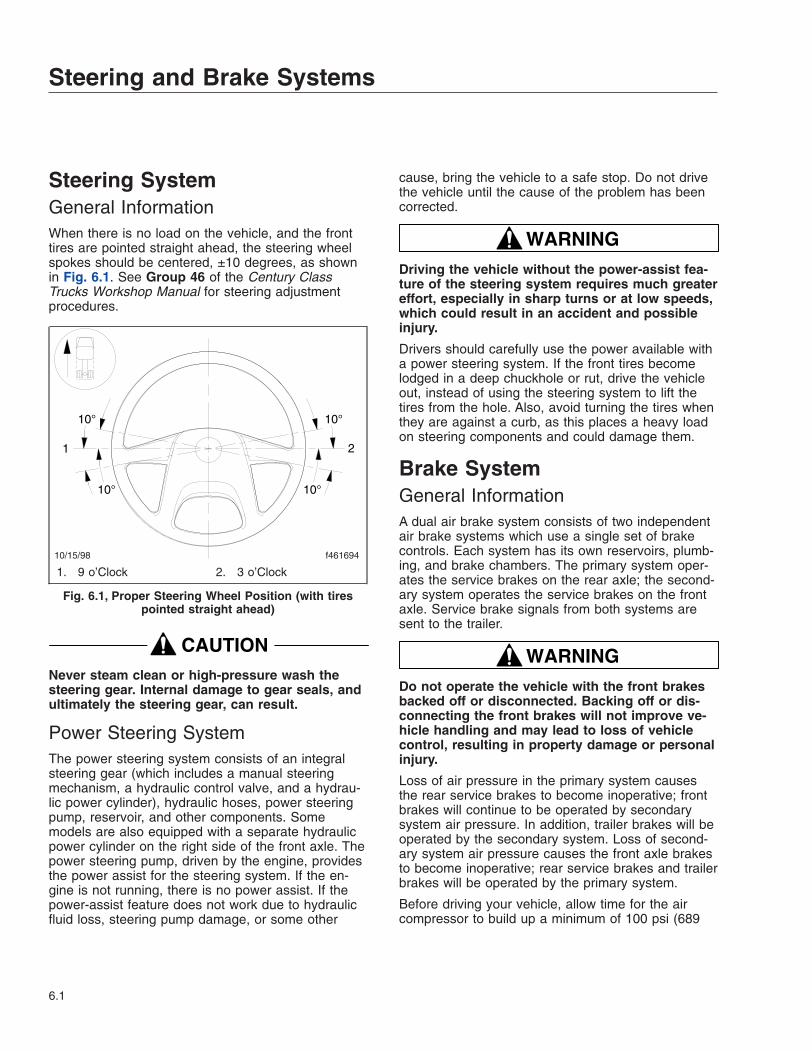
Steering SystemGeneral InformationWhen there is no load on the vehicle, and the fronttires are pointed straight ahead, the steering wheelspokes should be centered, ±10 degrees, as shownin Fig. 6.1. See Group 46 of the Century ClassTrucks Workshop Manual for steering adjustmentprocedures.
CAUTIONNever steam clean or high-pressure wash thesteering gear. Internal damage to gear seals, andultimately the steering gear, can result.
Power Steering SystemThe power steering system consists of an integralsteering gear (which includes a manual steeringmechanism, a hydraulic control valve, and a hydrau-lic power cylinder), hydraulic hoses, power steeringpump, reservoir, and other components. Somemodels are also equipped with a separate hydraulicpower cylinder on the right side of the front axle. Thepower steering pump, driven by the engine, providesthe power assist for the steering system. If the en-gine is not running, there is no power assist. If thepower-assist feature does not work due to hydraulicfluid loss, steering pump damage, or some other
cause, bring the vehicle to a safe stop. Do not drivethe vehicle until the cause of the problem has beencorrected.
WARNINGDriving the vehicle without the power-assist fea-ture of the steering system requires much greatereffort, especially in sharp turns or at low speeds,which could result in an accident and possibleinjury.
Drivers should carefully use the power available witha power steering system. If the front tires becomelodged in a deep chuckhole or rut, drive the vehicleout, instead of using the steering system to lift thetires from the hole. Also, avoid turning the tires whenthey are against a curb, as this places a heavy loadon steering components and could damage them.
Brake SystemGeneral InformationA dual air brake system consists of two independentair brake systems which use a single set of brakecontrols. Each system has its own reservoirs, plumb-ing, and brake chambers. The primary system oper-ates the service brakes on the rear axle; the second-ary system operates the service brakes on the frontaxle. Service brake signals from both systems aresent to the trailer.
WARNINGDo not operate the vehicle with the front brakesbacked off or disconnected. Backing off or dis-connecting the front brakes will not improve ve-hicle handling and may lead to loss of vehiclecontrol, resulting in property damage or personalinjury.
Loss of air pressure in the primary system causesthe rear service brakes to become inoperative; frontbrakes will continue to be operated by secondarysystem air pressure. In addition, trailer brakes will beoperated by the secondary system. Loss of second-ary system air pressure causes the front axle brakesto become inoperative; rear service brakes and trailerbrakes will be operated by the primary system.
Before driving your vehicle, allow time for the aircompressor to build up a minimum of 100 psi (689
10/15/98 f461694
10°
10°
1 2
10°
10°
1. 9 o’Clock 2. 3 o’Clock
Fig. 6.1, Proper Steering Wheel Position (with tirespointed straight ahead)
Steering and Brake Systems
6.1

kPa) pressure in both the primary and secondarysystems. Monitor the air pressure system by observ-ing the dual system air pressure gauge and the low-air-pressure warning light and buzzer. The warninglight and buzzer shut off when air pressure in bothsystems reaches 64 to 76 psi (441 to 524 kPa).
The warning light and buzzer come on if air pressuredrops below 64 to 76 psi (441 to 524 kPa) in eithersystem. If this happens, check the dual system airpressure gauge to determine which system has lowair pressure. Although the vehicle’s speed can bereduced using the foot brake control pedal, either thefront or rear service brakes will not be operating,causing a longer stopping distance. Bring the vehicleto a safe stop, and have the air system repaired be-fore continuing.
IMPORTANT: In the event of a total loss of ser-vice brakes with full system air pressure, usethe parking brake control valve (yellow knob) tobring the vehicle to a complete stop in the saf-est location possible.
On tractor-trailer vehicles, if both the primary andsecondary systems become inoperative, the trailerservice brakes or spring parking brakes will automati-cally apply when air pressure drops below 35 to 45psi (242 to 310 kPa). The tractor spring parkingbrakes will automatically apply when air pressuredrops below 20 to 30 psi (138 to 207 kPa). Onstraight trucks, spring parking brakes will apply whenair pressure drops below 20 to 30 psi (138 to 207kPa). Do not wait for the brakes to apply automati-cally. When the warning light and buzzer first comeon, immediately bring the vehicle to a safe stop. Be-fore continuing operation of the vehicle, correct thecause of the air loss.
Before the vehicle can be moved, the spring parkingbrakes must be released by applying an external airsource at the gladhands, or by manually caging theparking brake springs.
WARNINGDo not release (cage) the spring parking brakesand then drive the vehicle. There would be nomeans of stopping the vehicle, and this couldresult in serious personal injury or vehicle dam-age. Before releasing (caging) the spring parkingbrakes, make the connection to a towing vehicle,or chock the tires.
After correcting the brake system problem, uncagethe spring parking brakes before resuming normalvehicle operation.
Brake System OperationBefore driving the vehicle, secure all loose items inthe cab so that they will not fly forward during a fullbrake application. Make sure all passengers arewearing seat belts.
During normal brake stops, depress the foot brakecontrol pedal until braking action slows down the ve-hicle. Increase or decrease the pressure on thepedal so that the vehicle comes to a smooth, safestop. Apply the spring parking brakes if the vehicle isto be parked.
IMPORTANT: An air brake proportioning systemis used in tractor air brake systems when thevehicle is not equipped with ABS. When operat-ing in bobtail mode, the rear brake chambers(whose axle load has been greatly reduced) re-ceive reduced or proportional air pressure, whilethe front axle brake chambers receive full (nor-mal) air pressure. This results in a differentbrake pedal "feel," as the pedal seems to re-quire more travel and/or effort to slow or stopthe vehicle. However, the air brake proportioningsystem actually improves vehicle control whenthe tractor is in the bobtail mode of operation.When the tractor is towing a trailer, the rearbrake chambers will receive full (normal) appli-cation air pressure.
NOTE: If equipped with main and auxiliarytransmissions, do not shift both transmissionsinto neutral while the vehicle is rolling. Shiftingboth transmissions back into gear would be diffi-cult while the vehicle is rolling.
The trailer brake hand control valve (Fig. 6.2) actu-ates the trailer service brakes independently from thevehicle chassis service brakes. The valve can bepartially or fully applied, but in any partially-on posi-tion it will be overridden by a full application of thefoot brake control pedal. Moving the valve handleclockwise actuates the trailer brakes, while moving itcounterclockwise releases the trailer brakes. Thevalve handle is spring-loaded and returns to it’s origi-nal, no-air application position when released.
Steering and Brake Systems
6.2

WARNINGDo not use the trailer service brakes for parking;they are not designed for this purpose. If airbleeds out of the trailer air tank during parking,the vehicle could roll, causing serious personalinjury or property damage.
The red octagonal-shaped knob (Fig. 6.3) in the con-trol panel actuates the trailer air supply valve. Afterthe vehicle’s air hoses are connected to a trailer, andthe pressure in both air systems is at least 65 psi(448 kPa), the red knob must be pushed in. It shouldstay in, to charge the trailer air supply system and torelease the trailer spring parking brakes. It must bepulled out before disconnecting a trailer. It must alsobe pulled out when operating a vehicle without atrailer. If pressure in both air systems drops to 35 to45 psi (242 to 310 kPa), the red knob automaticallypops out, exhausting the trailer air supply, and apply-ing the trailer service or spring parking brakes.
The yellow diamond-shaped knob (Fig. 6.3) in thecontrol panel actuates the parking brake valve. Pull-ing out the knob applies both the tractor and trailerspring parking brakes and automatically causes thetrailer air supply valve knob to pop out.
CAUTIONDo not use the spring parking brakes if the ser-vice brakes are hot, such as after descending asteep grade. Also, do not use the spring parkingbrakes during freezing temperatures if the ser-
vice brakes are wet. To do so could damage thebrakes if hot, or cause them to freeze during coldweather.
If the brakes are wet, drive the vehicle in lowgear and lightly apply the brakes to heat and drythem. Allow hot brakes to cool before using thespring parking brakes. Always chock the tires.
If the trailer is not equipped with spring parkingbrakes, pulling out the yellow knob applies the tractorspring parking brakes and the trailer service brakes.When the tractor and trailer parking brakes (or trailerservice brakes) are both applied, the trailer brakesare released by pushing in the red knob, leaving thetractor parking brakes applied. Air pressure in theprimary or secondary reservoir must be at least 65psi (447 kPa) before the tractor spring parkingbrakes, or the trailer service or spring parkingbrakes, can be released.
On trailers not equipped with spring parking brakes,chock the trailer tires before disconnecting the truckor tractor when parking just the trailer.
When parking a truck or tractor with a trailer (combi-nation vehicle), and the trailer is not equipped withspring parking brakes, apply the truck or tractorspring parking brakes.
WARNINGIf a trailer is not equipped with spring parkingbrakes, do not park it or a combination vehicleby pulling out only the trailer air supply valveknob. This would apply only the trailer servicebrakes. If air were to bleed from the trailer brakesystem, the trailer brakes would release, possiblycausing an unattended runaway vehicle.
9/26/95 f461056
12
3
1. Turn Signal Lever2. Trailer Brake Hand Control Valve3. Hazard Warning Light Tab
Fig. 6.2, Steering Column-Mounted Controls (left-handdrive shown)
f610291
1 2
03/10/99
1. Trailer Air Supply Valve Knob2. Parking Brake Valve Knob
Fig. 6.3, Brake Valve Knobs
Steering and Brake Systems
6.3
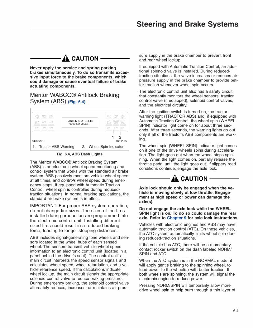
CAUTIONNever apply the service and spring parkingbrakes simultaneously. To do so transmits exces-sive input force to the brake components, whichcould damage or cause eventual failure of brakeactuating components.
Meritor WABCO® Antilock BrakingSystem (ABS) (Fig. 6.4)
The Meritor WABCO® Antilock Braking System(ABS) is an electronic wheel speed monitoring andcontrol system that works with the standard air brakesystem. ABS passively monitors vehicle wheel speedat all times, and controls wheel speed during emer-gency stops. If equipped with Automatic TractionControl, wheel spin is controlled during reduced-traction situations. In normal braking applications, thestandard air brake system is in effect.
IMPORTANT: For proper ABS system operation,do not change tire sizes. The sizes of the tiresinstalled during production are programmed intothe electronic control unit. Installing differentsized tires could result in a reduced brakingforce, leading to longer stopping distances.
ABS includes signal-generating tone wheels and sen-sors located in the wheel hubs of each sensedwheel. The sensors transmit vehicle wheel speedinformation to an electronic control unit (located in apanel behind the driver’s seat). The control unit’smain circuit interprets the speed sensor signals andcalculates wheel speed, wheel retardation, and a ve-hicle reference speed. If the calculations indicatewheel lockup, the main circuit signals the appropriatesolenoid control valve to reduce braking pressure.During emergency braking, the solenoid control valvealternately reduces, increases, or maintains air pres-
sure supply in the brake chamber to prevent frontand rear wheel lockup.
If equipped with Automatic Traction Control, an addi-tional solenoid valve is installed. During reduced-traction situations, the valve increases or reduces airpressure supply in the brake chamber to provide bet-ter traction whenever wheel spin occurs.
The electronic control unit also has a safety circuitthat constantly monitors the wheel sensors, tractioncontrol valve (if equipped), solenoid control valves,and the electrical circuitry.
After the ignition switch is turned on, the tractorwarning light (TRACTOR ABS) and, if equipped withAutomatic Traction Control, the wheel spin (WHEELSPIN) indicator light come on for about three sec-onds. After three seconds, the warning lights go outonly if all of the tractor’s ABS components are work-ing.
The wheel spin (WHEEL SPIN) indicator light comeson if one of the drive wheels spins during accelera-tion. The light goes out when the wheel stops spin-ning. When the light comes on, partially release thethrottle pedal until the light goes out. If slippery roadconditions continue, engage the axle lock.
CAUTIONAxle lock should only be engaged when the ve-hicle is moving slowly at low throttle. Engage-ment at high speed or power can damage theaxle(s).
Do not engage the axle lock while the WHEELSPIN light is on. To do so could damage the rearaxle. Refer to Chapter 9 for axle lock instructions.
Vehicles with electronic engines and ABS may haveautomatic traction control (ATC). On these vehicles,the ATC system automatically limits wheel spin dur-ing reduced-traction situations.
If the vehicle has ATC, there will be a momentarycontact rocker switch on the dash labeled NORM/SPIN and ATC.
When the ATC system is in the NORMAL mode, itwill apply gentle braking to the spinning wheel, tofeed power to the wheel(s) with better traction. Ifboth wheels are spinning, the system will signal theelectronic engine to reduce power.
Pressing NORM/SPIN will temporarily allow moredrive wheel spin to help burn through a thin layer of
FASTEN SEATBELTS0000432 MILES
2f60112504/02/96
1
1. Tractor ABS Warning 2. Wheel Spin Indicator
Fig. 6.4, ABS Dash Lights
Steering and Brake Systems
6.4
ice, or to help throw off accumulated mud or snow.SPIN mode is indicated by a flashing WHEEL SPINlight. Pressing NORM/SPIN again will cycle the sys-tem back to normal operation.
The Meritor WABCO® ABS system combines onefront-axle control channel with one rear axle to formone control circuit. For example, the sensor and sole-noid control valve on the left-front axle form a controlcircuit with the sensor and solenoid control valve onthe right rear axle. If, during vehicle operation, thesafety circuit senses a failure in any part of the ABSsystem (a sensor, solenoid control valve, wiring con-nection, short circuit, etc.), the tractor warning light(TRACTOR ABS) comes on and the control circuitwhere the failure occurred is switched to normalbraking action. The remaining control circuit will re-tain the ABS effect. Even if the ABS system is com-pletely inoperative, normal braking ability is main-tained. An exception would be if a solenoid controlvalve (or combination solenoid control valve) is dam-aged and inoperative. As these components are anintegral part of the air brake system, normal brakingmay be impaired or inoperative.
IMPORTANT: If any of the ABS warning lightsdo not work as described above, or come onwhile driving, repair the ABS system immedi-ately to ensure full antilock braking capability.
During emergency or reduced-traction stops, fullydepress the brake pedal until the vehicle comes to asafe stop; do not pumpthe brake pedal. With thebrake pedal fully depressed, the ABS system willcontrol all wheels to provide steering control and areduced braking distance.
Although the ABS system improves vehicle controlduring emergency braking situations, the driver stillhas the responsibility to change driving styles de-pending on the existing traffic and road conditions.For example, the ABS system cannot prevent an ac-cident if the driver is speeding or following tooclosely.
Trailer ABS Lamp OperationAntilock braking systems on tractors are designed tocommunicate with trailer ABS systems, if they arecompatible. Compatibility will result in the illuminationof the trailer ABS lamp during vehicle start-up andfault detection.
The dash-mounted lamp will operate as follows whena compatible trailer is properly connected to a tractor:
• When the ignition key is turned to the ON posi-tion, the trailer ABS lamp will illuminate mo-mentarily, then turn off.
• If the lamp comes on momentarily during ve-hicle operation, then shuts off, a fault was de-tected and corrected.
• If the lamp comes on and stays on during ve-hicle operation, there is a fault with the trailerABS. Repair the trailer ABS system immedi-ately to ensure full antilock braking capability.
The Trailer ABS lamp will not illuminate unless acompatible trailer is connected to the tractor.
IMPORTANT: If a compatible trailer is con-nected, and the lamp is not illuminating momen-tarily when the ignition key is turned to the ONposition, it is possible that the lamp is burnt out.
Meritor WABCO® Electronic BrakingSystem (EBS)The Meritor WABCO® Electronic Braking System(EBS) is designed to continuously monitor and coor-dinate all aspects of service braking.
The EBS pairs an electronic control system with apneumatic application system. Key braking data suchas driver brake demand, wheel speed, and vehicleload is gathered by a network of electronic sensingdevices (including load sensors, and signal generat-ing tone wheels and sensors located in the wheelhubs of each sensing axle).
An electronic control unit, the central module, over-sees the translation of electronic signals into pneu-matic actuation. During a braking application,electronic-pneumatic modulators control the brakepressure of each wheel, as well as at the trailer cou-pling head. As a result, the same amount of vehicledeceleration will occur for a given brake pedal travel,regardless of vehicle load. During emergency stops(i.e. wheel lockup), the EBS also activates the An-tilock Braking System (ABS).
The EBS includes a system check for all modulators,sensors, brake system electric circuits and data linesand is thereby able to detect malfunctions in thebraking system. When a fault is detected, the centralmodule will disable the affected part of the EBS.Under this safe status (i.e. fail-safe) mode, the nonaf-fected parts will continue to function. For example, inthe case of a sensor malfunction, the system works
Steering and Brake Systems
6.5
without the sensor information but at a reduced per-formance level.
If a serious malfunction causes a total switch-off ofone or more electronic braking circuits, a pure pneu-matic backup system is available.
The following functions can be deactivated in theevent of a malfunction:
• ABS can be deactivated at one individualwheel, at one axle, or for the whole vehicle.
• ATC control can be deactivated. If it is shutdown, then both the brake control and the en-gine control will be shut down.
• If electrical control is lost, the affected axle isbraked by means of the pneumatic redundancypressure. The driver must compensate by ex-erting more force on the brake pedal to stopthe vehicle.
This system has built-in diagnostics to ensure that allcomponents are operating properly. Under normalconditions, the system performs a three second self-check when the ignition is turned on. The two warn-ing lamps (EBS, ABS) and the information lamp(ATC) should illuminate for three seconds and thengo out if all EBS components are working properly. Ifall three lamps do not switch on or if all three lampsdo not switch off after three seconds, the systemshould be checked.
NOTE: If there is no bulb check and no dis-played fault, most likely the brake pedal is par-tially depressed, either by the driver or by some-thing holding the pedal down. This safetyfeature alerts the driver that the brake pedal isnot fully in the released position.
Automatic Slack AdjustersAutomatic slack adjusters are required on all vehiclesequipped with air brakes manufactured after October20, 1994. Automatic slack adjusters should never bemanually adjusted except during routine maintenanceof the foundation brakes (e.g., replacing shoes), dur-ing slack adjuster installation or in an emergencysituation.
When the brake pushrod stroke exceeds the legalbrake adjustment limit on a vehicle, there is likely amechanical problem with the foundation brake com-ponents or the adjuster is improperly installed.
Visit a repair facility as soon as possible whenbrakes equipped with automatic slack adjusters aredetermined to be out of adjustment.
WARNINGManually adjusting an automatic slack adjuster tobring the pushrod stroke within legal limits islikely masking a mechanical problem. Adjustmentis not repairing. In fact, continual adjustment ofautomatic slack adjusters may result in prema-ture wear of the adjuster itself. Further, the im-proper adjustment of some automatic slack ad-justers may cause internal damage to theadjuster, thereby preventing it from properlyfunctioning.
Steering and Brake Systems
6.6

7
Engines and ClutchesEPA07 Aftertreatment System (ATS) . . . . . . . . . . . . . . . . . . . . . . . . . . . . . . . . . . . . . . . . . . . . . . . . . . 7.1DD15 Heavy-Duty Engine . . . . . . . . . . . . . . . . . . . . . . . . . . . . . . . . . . . . . . . . . . . . . . . . . . . . . . . . . . 7.3Engine Starting—CAT, Cummins, DDE S60, M-B . . . . . . . . . . . . . . . . . . . . . . . . . . . . . . . . . . . . . . . 7.6Starting After Extended Shutdown or Oil Change—CAT, Cummins, DDE S60, M-B . . . . . . . . . . . 7.10Engine Break-In—CAT, Cummins, DDE S60, M-B . . . . . . . . . . . . . . . . . . . . . . . . . . . . . . . . . . . . . . 7.10Engine Operation—CAT, Cummins, DDE S60, M-B . . . . . . . . . . . . . . . . . . . . . . . . . . . . . . . . . . . . . 7.11Cold-Weather Operation—CAT, Cummins, DDE S60, M-B . . . . . . . . . . . . . . . . . . . . . . . . . . . . . . . 7.15High-Altitude Operation—CAT, Cummins, DDE S60, M-B . . . . . . . . . . . . . . . . . . . . . . . . . . . . . . . . 7.18Engine Shutdown—CAT, Cummins, DDE S60, M-B . . . . . . . . . . . . . . . . . . . . . . . . . . . . . . . . . . . . . 7.18Engine Braking System—CAT, Cummins, DDE S60, M-B . . . . . . . . . . . . . . . . . . . . . . . . . . . . . . . . 7.20Exhaust Braking System—CAT, Cummins, DDE S60, M-B . . . . . . . . . . . . . . . . . . . . . . . . . . . . . . . 7.22Clutches . . . . . . . . . . . . . . . . . . . . . . . . . . . . . . . . . . . . . . . . . . . . . . . . . . . . . . . . . . . . . . . . . . . . . . . 7.23

EPA07 Aftertreatment System(ATS)On-road diesel engines built after December 31,2006 are required to meet EPA07 guidelines for re-duced exhaust emissions of particulate matter andnitrogen oxides (NOx). NOx is limited to just over 1gram per brake horsepower hour (g/bhp-hr), and par-ticulate matter cannot exceed 0.01 g/bhp-hr.
EPA07-compliant engines require ultralow-sulfur die-sel (ULSD) fuel, and they should never be run onfuel with sulfur content higher than 15 ppm. In addi-tion, they require low-ash engine oil. The followingguidelines must be followed, or the warranty may becompromised.
• Use ultralow-sulfur diesel (ULSD) with 15 ppmsulfur content or less, based on ASTM D2622test procedure.
• Do not use fuel blended with used engine lubeoil.
• Engine lube oil must have a sulfated ash levelless than 1.0 wt %, meeting the API CJ-4 indexspecifications.
IMPORTANT: Using non-specification fuels oroils can lead to shortened diesel particulate filter(DPF) cleaning or exchange intervals. For ex-ample, using CI-4+ oil with 1.3% sulfated ash(30% more ash content) may result in the needfor DPF cleaning or exchange 20 to 30% soonerthan would normally be required.
The "exhaust system" in EPA07-compliant vehicles iscalled the aftertreatment system (ATS). The ATS var-ies according to engine manufacturer and vehicleconfiguration, but instead of a muffler, an aftertreat-ment system has a device that outwardly resemblesa muffler, called the aftertreatment device (ATD).
IMPORTANT: See your engine operation manualfor complete details and operation of the after-treatment system.
Inside the ATD on Mercedes-Benz, Detroit Diesel,and Cummins engines, the exhaust first passes overthe diesel oxidation catalyst (DOC), then it passesthrough the diesel particulate filter (DPF), which trapssoot particles. If exhaust temperature is high enough,the trapped soot is reduced to ash, in a processcalled passive regeneration (regen). Passive regen-
eration occurs as the vehicle is driven normallyunder load; the driver is not even aware that it ishappening. The harder an EPA07 engine works, thebetter it disposes of soot, as the exhaust heat aloneis enough to burn the soot to ash. Over the course ofa workday, however, passive regeneration cannotalways keep the ATD filter clean, so the filter mustundergo active regeneration. In active regeneration,extra fuel is injected into the exhaust stream to su-perheat the soot trapped in the DPF and turn it toash. Active regeneration happens only when the ve-hicle is moving above a certain speed, determined bythe engine manufacturer. Consult manufacturers’documentation for details.
Both active and passive regeneration happen auto-matically, without driver input.
NOTE: Caterpillar engines do not use a DOC;CAT engines burn diesel fuel at the regenerationhead to superheat the exhaust and burn thetrapped soot to ash. Engine software monitorsand controls this process.
Only when operating conditions do not allow for ATDfilter cleaning by at-speed active or passive regen-eration, the vehicle may require a driver-activatedparked regeneration. The vehicle must be standingstill, and the driver must initiate a parked regen.Completing a parked regen takes 20 minutes to anhour, depending on ambient conditions.
DANGERDuring parked regeneration, exhaust tempera-tures are very high, and could cause a fire, heatdamage to objects or materials, or personal in-jury to persons near the exhaust outlet.
Before initiating a parked regeneration, make cer-tain the exhaust outlets are directed away fromstructures, trees, vegetation, flammable materi-als, and anything else that may be damaged orinjured by prolonged exposure to high heat.
The warning lamps in the driver message center alertthe driver of a regen in progress, high exhaust tem-peratures, the need to perform a parked regen eithersoon or immediately, and of an engine fault that af-fects the emissions.
A slow (10-second) flashing of the high exhaust sys-tem temperature (HEST) lamp indicates that aparked regeneration is in progress, and the engine’s
Engines and Clutches
7.1

high idle speed is being controlled by the enginesoftware, not the driver.
A steadily illuminated high temperature (HEST) lampalerts the operator of high exhaust temperature dur-ing the regeneration process, if vehicle speed isbelow 5 mph (8 km/h). The HEST lamp does not sig-nify the need for any kind of vehicle or engine ser-vice; it only alerts the vehicle operator of high ex-haust temperatures. Make sure the engine exhaustpipe outlet is not directed at any person, or at anysurface or material that will melt, burn, or explode.See Fig. 7.1.
WARNINGActive regeneration can occur automatically any-time the vehicle is moving. The exhaust gas tem-perature could reach 1500°F (816°C), which is hotenough to cause a fire, heat damage to objectsor materials, or personal injury to persons nearthe exhaust outlet. See Regen-Inhibit Switch laterin this chapter for instructions on preventing au-tomatic regen if necessary.
The exhaust temperature can remain high evenafter the vehicle has stopped. When stopping thevehicle shortly after an automatic regen, ensurethe exhaust outlets are directed away from struc-tures, trees, vegetation, flammable materials, andanything else that may be damaged or injured byexposure to high heat.
A steadily illuminated yellow diesel particulate filter(DPF) lamp indicates that a regen may be requiredsoon. Bring the vehicle to highway speeds to allowfor an active regen, or a parked regen should be
scheduled for the earliest convenient time. SeeFig. 7.2.
A DPF lamp blinking at the same time as a steadilyilluminated yellow Check Engine lamp, indicates thata parked regen must be performed immediately, oran engine derate will occur. If the red Stop Enginelamp illuminates with the blinking DPF lamp and theCheck Engine lamp, a parked regen must occur oran engine shutdown will occur. Park the vehicle andperform a parked regen. See Fig. 7.3.
A steadily illuminated yellow malfunction indicatorlamp (MIL) indicates an engine fault that affects theemissions. See Fig. 7.4.
When diesel particulate filter servicing is needed, itmust be performed by an authorized technician, anda record must be maintained for warranty purposes.The record must include:
• date of cleaning or replacement;
• vehicle mileage;
• particulate filter part number and serial number.
09/25/2006 f610816a
Fig. 7.1, High Exhaust System Temperature (HEST)Lamp
09/25/2006 f610815a
Fig. 7.2, Diesel Particulate Filter (DPF) Status Lamp
03/20/2008 f6110001 2 3
CHECK STOP
1. Stop Engine Override Switch2. Amber Check Engine Warning Lamp3. Red Stop Engine Lamp
Fig. 7.3, Engine Lamps
Engines and Clutches
7.2

The request/inhibit regen switch (Fig. 7.5), locatedon the dash, can have three selectable positions:
• request regeneration;
• default (either automatic regeneration or inhibitstate);
• inhibit regeneration.
NOTE: The regen switch can start a parkedregen only when at least one of two conditionsexists: either the DPF light is lit, or the enginesoftware calls for it. If neither of those conditionsexist, the regen switch cannot cause a regen-eration to happen.
The function of the switch will vary by the enginemake and model in the vehicle. See the engine op-eration manual for switch operation details.
DD15 Heavy-Duty EngineSee Chapter 2 of this manual for information on theDDEC VI operator controls. See the Detroit DieselDD15 Engine Operator’s Guide for complete detailsof engine operation.
Engine ProtectionAn engine protection system monitors all engine sen-sors and electronic components, and recognizes sys-tem malfunctions. If a critical fault is detected, anamber Check Engine warning lamp and a red StopEngine lamp illuminate. See Fig. 7.3.
The standard parameters that are monitored for en-gine protection are: low coolant level, high coolanttemperature, low oil pressure, and high oil tempera-ture.
Amber Check Engine Warning LampWhen the amber Check Engine warning lamp comeson for any reason, the vehicle can still be operated,and the driver can proceed to the required destina-tion. See Fig. 7.3. This condition should be reportedto an authorized service center as soon as possible.
Red Stop Engine LampWhen the red Stop Engine lamp comes on, the com-puter has detected a major malfunction in the enginethat requires immediate attention. See Fig. 7.3. It isthe operator’s responsibility to shut down theengine to avoid serious damage. This system fea-tures a 30-second, stepped-down power-shutdownsequence, or an immediate emergency-runningmode, in the event that a major engine malfunctionoccurs. The conditions that will cause the red StopEngine lamp to come on are:
• high coolant temperature
• loss of coolant
• high oil temperature
• low oil pressure
• auxiliary shutdown
Stop Engine Override SwitchIn the event that the vehicle is operating in a criticallocation when a shutdown is initiated, a Stop EngineOverride (SEO) switch can be used to override the
09/25/2006 f610814a
Fig. 7.4, Malfunction Indicator Lamp (MIL)
f61084803/09/2012
RGEN
Fig. 7.5, Request/Inhibit Regen Switch
Engines and Clutches
7.3
shutdown sequence. See Fig. 7.3. This override re-sets the shutdown timer, restoring power to the levelwhen the red stop engine lamp was illuminated. Theswitch must be recycled after five seconds to obtaina subsequent override.
CAUTIONUsing the override button so the engine operatesfor an extended period may result in engine dam-age. The operator has the responsibility to takeaction to avoid engine damage.
DDEC VI Driving TipsAccelerating the VehicleThe accelerator pedal was designed to communicate“percentage” of accelerator pedal travel to the engineMCM. A throttle characteristic you may need time toget used to, is the DDEC limiting speed governor.This allows the driver to command total engine re-sponse between idle and rated speed, such as accel-erating at half throttle—an advantage when drivingunder slippery conditions. To obtain 100 percent fuel-ing at any speed, the accelerator pedal must be de-pressed to the fully pressed position.
ShiftingDepending on your transmission model, the gear splitmay vary from 400 to 500 rpm. The electronic gover-nor provides almost no overrun capability; if thetransmission is downshifted too early, you will experi-ence a temporary loss of pulling power until the en-gine speed falls below rated speed. In general, whenusing a 9-speed transmission, you should alwaysdownshift between 1000 and 1100 rpm. This is trueeven on steep grades with heavy loads. When usingan 18-, 15-, or 13-speed transmission, you will needto downshift at an rpm that allows “less than rated”rpm, before throttle application in the next geardown. You may want to limit engine speed to 1900rpm in all gears.
The DD15 engine provides horsepower through 2100rpm, but fuel economy is not as efficient above 1800rpm. If you decide to drive at lower rpm for improvedfuel economy, don’t let different engine noises throwyou off guard. The DD15 engine sounds quiet at1400 rpm, almost as if it had quit pulling. If you hada boost gauge to look at while driving, you would no-tice the turbocharger maintaining steady intake mani-fold pressure, even as rpm falls. Depending on the
air intake arrangement, you may also hear a “chuff-ing” sound as the engine starts to pull hard at lowerrpm. This is normal, and caused by the velocitychanges of the air flow within the air intake plumbing.Electronic engines can actually deliver more fuel atlower engine speeds than at rated speed.
The DD15 engine has been designed for a very quietoperation, but the air flow may be noticeable to thetuned attentive ear. The turbocharger operates athigher boost pressure, forcing exhaust to flowthrough the exhaust gas recirculation plumbing. Insome situations the driver may believe they have ex-perienced a charge air cooler system leak. Evenwhile connecting trailer lights and air hoses, thedriver may hear a different tone (exhaust and underhood with the engine idling). If equipped with a turboboost gauge, the driver may occasionally note theintake manifold pressure exceeds 35 psi (241 kPa).
IdlingThe common belief that idling a diesel engine causesno engine damage is wrong. Idling produces sulfuricacid, that is absorbed by the lubricating oil, and eatsinto bearings, rings, valve stems, and engine sur-faces. If you must idle the engine for cab heat orcooling, the high idle function of the cruise controlswitches should be used. An idle speed of 900 rpmshould be enough to provide cab heat in abovefreezing ambient temperatures.
Cold-Weather OperationPrecautions must be taken during cold weather toprotect your engine. Special cold-weather handling isrequired for fuel, engine oil, coolant, and batteries.The engine does not require starting aids down to50°F (10°C). A grid heater is included for tempera-tures between 50°F (10°C) and –4°F (–20°C). Tem-peratures below –4°F (–20°C), will require a gridheater, block heater, and oil pan heater.
CAUTIONNEVER use ether as a starting aid on a DD HDengine. Doing so will result in injector damage.
A winterfront may be used to improve cab heating. Atleast 25 percent of the grill opening should remainopen in sectioned stripes that run perpendicular tothe charge air cooler tube flow direction. This as-sures even cooling across each tube, and reduces
Engines and Clutches
7.4

header-to-tube stress and possible failure. Winter-fronts should only be used when the ambient tem-perature remains below 10°F (–12°C).
Driving on Flat, Dry PavementUse the following guidelines when driving on flat, drypavement.
• If driving on flat, dry, open stretches, with alight load, place the progressive braking switchin the LOW position.
• If you find you are still using the servicebrakes, move the switch to a higher positionuntil you do not need to use the service brakesto slow the vehicle.
• If you are carrying a heavier load and roadtraction is good, move the progressive brakingswitch to the HIGH position.
• Check your progressive braking switch oftenfor proper position, since road conditions canchange quickly. Never skip a step when oper-ating the progressive braking switch. Always gofrom OFF to LOW, and then to a higher posi-tion.
Descending a Long, Steep GradeAn explanation of “control speed” may be helpful inunderstanding how to use the engine brake systemwhile descending a grade. Control speed is the con-stant speed at which the forces pushing the vehicleforward on a grade, are equal to the forces holding itback, without using the vehicle service brakes. Inother words, this is the speed the vehicle will main-tain without using the service brakes or throttle.
CAUTIONDo not over apply the vehicle service brakeswhen descending a long, steep grade. Excessiveuse of the vehicle brakes will cause them to heatup, reducing their stopping ability. This condi-tion, referred to as “brake fade”, may result inloss of braking, which could lead to loss of con-trol of the vehicle, resulting in personal injury orproperty damage.
Use the following guidelines when descending along, steep grade.
• Before beginning the descent, determine ifyour engine brake system is operating prop-
erly, by lifting your foot briefly off the accelera-tor pedal. You should feel the system activate.
• Ensure the progressive braking switch is in theappropriate power position. Check your pro-gressive braking switch often for proper posi-tion, since road conditions can change quickly.Never skip a step when operating the progres-sive braking switch. Always go from OFF toLOW and then to a higher position when onslippery roads.
• Do not exceed the safe control speed of yourvehicle. Example: You could descend a 6 per-cent grade, under control at 10 mph (16 km/h)without an engine brake, but at 25 mph (40km/h) it requires an engine brake. You couldnot descend that same hill at 50 mph (80km/h) and still expect to remain under control.Know how much slowing power your enginebrake can provide before descending hills, anddo not exceed a safe control speed.
Driving on Wet or Slippery Pavement
WARNINGTo avoid injury from loss of vehicle control, donot activate the engine brake system under thefollowing conditions:
• on wet or slippery pavement
• when driving without a trailer (bobtailing) orpulling an empty trailer
• if the tractor drive wheels begin to lock, orthere is fishtail motion after the enginebrake is activated
NOTE: On single trailers or combinations, a lightair application of the trailer brakes may be desir-able to help keep the trailer stretched out. Fol-low the manufacturer’s recommended operatingprocedure when using the trailer brakes.
On wet or slippery pavement, start with the masterswitch in the OFF position and use the gear youwould normally use under these conditions. If thevehicle is maintaining traction, place the selectivebraking switch in the LOW position and turn ON theengine brake system. If the drive wheels are main-taining traction and you desire greater slowing power,move the braking switch to the next higher position.However, if the tractor drive-wheels begin to lock, or
Engines and Clutches
7.5

there is a fishtail motion, turn the engine brake sys-tem OFF immediately and do not activate it until roadconditions improve.
Check your progressive engine braking switch oftenfor proper position, since road conditions can changequickly. Never skip a step when operating the pro-gressive braking system. Always go from OFF toLOW and then to a higher position. See Chapter 2for the proper operation of the engine brake.
Engine Starting—CAT,Cummins, DDE S60, M-BNormal StartingFor cold-weather starting, refer to "Cold-WeatherStarting" later in this chapter.
Whenever you start an engine, watch for any signsof engine problems. If the engine vibrates, misfires,or makes unusual noises, turn the engine off as soonas possible and determine the cause of the problem.Frequently, engine damage may be avoided by aquick response to early indications of problems.
CAUTIONWhen starting a vehicle equipped with a manualtransmission and clutch lockout switch, theclutch pedal must be fully depressed during theentire start sequence. Failure to do so can causethe pinion to release and re-engage, which couldcause ring gear and starter pinion damage.
If a vehicle does not start on the first attempt,make sure that the engine has completelystopped rotating before reapplying the starterswitch. Failure to do so can cause the pinion torelease and re-engage, which could cause ringgear and starter pinion damage.
Moving a vehicle with the starter and/or using thestarter to bump the engine for maintenance pro-cedures is strictly prohibited. Use of these meth-ods to bump the engine over or move the vehiclecan cause the pinion to release and re-engage,which could cause ring gear and starter piniondamage.
IMPORTANT: The starter can not be used forpriming the fuel system. Priming is done by op-erating the manual hand priming pump locatedon the fuel filter module, or connecting an elec-
tric priming pump to the priming port on the fuelfilter module. See the engine operation manualfor complete instructions.
Prestart
NOTE: These prestart steps apply to all en-gines.
1. Perform the engine pretrip inspection and dailymaintenance checks in Chapter 11.
2. Apply the parking brake.
NOTE: On vehicles equipped with a neutral startswitch, the transmission must be in neutral be-fore the engine can be started. For air start sys-tems, check the air supply before starting theengine. There must be 100 psi (689 kPa) of airpressure available.
3. For manual transmissions, place the transmis-sion in neutral and disengage the clutch.
For automatic transmissions, make sure thetransmission shift control is in neutral or park.
Starting Precautions
CAUTIONDo not crank the engine for more than 30 sec-onds at a time. Wait two minutes after each try toallow the starter to cool. Failure to do so couldcause starter damage.
NOTE: Some starters are equipped with op-tional overcrank protection. If overcranking oc-curs, a thermostat breaks the electrical circuit tothe starter motor until the motor has cooled.
CAUTIONProtect the turbocharger during the start-up bynot opening the throttle or accelerating the en-gine above 1000 rpm until minimum engine idleoil pressure registers on the gauge. Failure to doso could damage the turbocharger.
WARNINGNever pour fuel or other flammable liquid into theair inlet opening in the air intake in an attempt to
Engines and Clutches
7.6

start the vehicle. This could result in a flash firecausing serious personal injury or property dam-age.
WARNINGStarting fluid is highly flammable and explosive.It can cause serious injury or death if improperlyhandled. Do not smoke where starting fluid is inuse. Keep sparks, flames, and arc welding equip-ment away from starting fluid.
Caterpillar
NOTE: Before doing these steps, do the stepsin "Prestart".
1. Turn the ignition switch to the on position(Fig. 7.6). All the electronic gauges on the ICU(instrumentation control unit) complete a fullsweep of their dials, the warning and indicatorlights light up, and the buzzer sounds for threeseconds.
NOTE: The engine electronics supply the cor-rect amount of fuel for starting the engine. Pedalpressure is unnecessary.
2. Turn the ignition switch to the start position. Donot press down on the throttle pedal. Releasethe switch the moment the engine starts.
2.1 If the engine does not start after 30 sec-onds of cranking, turn the ignition switchoff.
NOTE: Some starters are equipped with op-tional overcrank protection. If overcrankingoccurs, a thermostat breaks the electricalcircuit to the starter motor until the motorhas cooled.
2.2 Wait two minutes to allow the startermotor to cool. Turn the ignition switchback to the on position and try again tostart the engine.
2.3 As soon as the engine starts, release theignition switch, allowing the engine to runat a slow idle.
CAUTIONIf the oil pressure is less than 5 psi (35 kPa), shutdown the engine immediately to prevent seriousdamage. If the vehicle is equipped with an auto-matic shutdown system, the engine will shutdown after 30 seconds.
3. Caterpillar C–10/C–12/C–15/C–16 engines maybe operated at low load and speed once the en-gine oil pressure has reached 10 to 20 psi (69 to138 kPa). Caterpillar 3406E engines may be op-erated at low load and speed once the engine oilpressure has reached 18 psi (124 kPa).
4. When the engine has reached the normal operat-ing temperature of 189°F (87°C), the engine maybe operated at full load.
Cummins
NOTE: Before doing these steps, do the stepsin "Prestart".
1. Turn the ignition switch to the on position(Fig. 7.6). All the electronic gauges on the ICU(instrumentation control unit) complete a fullsweep of their dials, the warning and indicatorlights light up, and the buzzer sounds for threeseconds.
2. Turn the ignition switch to the start position. Afterthe engine starts, release the key.
NOTE: Some starters are equipped with op-tional overcrank protection. If overcranking oc-curs, a thermostat breaks the electrical circuit tothe starter motor until the motor has cooled.
03/22/2001
OFF ON
ACC START
f602079
Fig. 7.6, Ignition Switch Positions
Engines and Clutches
7.7

3. Bring the engine up to operating speed graduallyas it warms up and develops stable oil pressure.
NOTE: When the engine is started, it takes ashort time to build up a lubricating oil film be-tween the shafts and bearings, and between thepistons and liners. The oil pressure gauge indi-cates any drop in lubricating oil pressure within15 seconds of engine start-up.
4. If minimum engine oil pressure at idle of 10 psi(69 kPa) does not register within 15 seconds,shut down the engine.
CAUTIONProtect the turbocharger during the start-up bynot opening the throttle or accelerating the en-gine above 1000 rpm until minimum engine idleoil pressure registers on the gauge. Failure to doso could damage the turbocharger.
5. Idle the engine for three to five minutes at 1000rpm before operating the engine under load.
DDE S60
NOTE: Before doing these steps, do the stepsin "Prestart".
1. Turn the ignition switch to the on position(Fig. 7.6). All the electronic gauges on the ICU(instrumentation control unit) complete a fullsweep of their dials, the warning and indicatorlights light up, and the buzzer sounds for threeseconds.
2. When all the indicators go out, turn the ignitionswitch to the start position. Without touching thethrottle pedal, start the engine. If the enginewon’t start within 15 seconds, release the ignitionswitch and allow the starter motor to cool.
IMPORTANT: If the engine won’t start, check themain engine power fuses. The fuses are locatedalong the main engine electrical harness on theleft frame rail, near the batteries. If the fuses areblown, replace the fuses. Be sure to find thecause of the blown fuses as soon as possible.
NOTE: Some starters are equipped with op-tional overcrank protection. If overcranking oc-curs, a thermostat breaks the electrical circuit tothe starter motor until the motor has cooled.
WARNINGNever pour fuel or other flammable liquid into theair inlet opening in the air intake in an attempt tostart the vehicle. This could result in a flash firecausing serious personal injury or property dam-age.
3. Check the oil pressure gauge immediately afterstarting the engine.
4. If no pressure registers within 10 to 15 secondsor the ENGINE PROTECT indicator comes on,shut down the engine and check the lubricatingoil system.
CAUTIONProtect the turbocharger during the start-up bynot opening the throttle or accelerating the en-gine above 1000 rpm until minimum engine idleoil pressure of 12 psi (83 kPa) registers on thegauge.
5. Idle the engine for about five minutes at 1000rpm before operating the engine under load.
Mercedes-Benz
NOTE: Before doing these steps, do the stepsin "Prestart".
CAUTIONNever attempt to start any Mercedes-Benz elec-tronic engine using ether or any other startingfluid. Serious engine damage could result.
1. Turn the ignition switch to the on position(Fig. 7.6). All the electronic gauges on the ICU(instrumentation control unit) complete a fullsweep of their dials, the warning and indicatorlights light up, and the buzzer sounds for threeseconds.
IMPORTANT: On vehicles equipped with an in-take air preheater, the INTAKE HEATER indica-tor stays on for a minimum of two seconds, re-gardless of coolant temperature. Wait until theINTAKE HEATER indicator goes out before at-tempting to start the engine.
Engines and Clutches
7.8

2. Turn the ignition switch to the start position.Without touching the throttle pedal, start the en-gine.
NOTE: Some starters are equipped with op-tional overcrank protection. If overcranking oc-curs, a thermostat breaks the electrical circuit tothe starter motor until the motor has cooled.
3. Idle the engine for one to three minutes at 600 to850 rpm before operating the engine under load.
4. Check the oil pressure gauge for any drop in lu-bricating oil pressure or mechanical malfunctionin the lubricating oil system. Minimum oil pres-sure at idle is 7 psi (50 kPa).
CAUTIONDo not rev the engine if the oil pressure gaugeindicates no oil pressure. Shut down the engineif no oil pressure appears within approximatelyten seconds. Check to determine the cause of theproblem. Operating the engine with no oil pres-sure will damage the engine.
Cold-Weather StartingModern electronic engines do not normally requirespecial starting aids. At low temperatures, oil panheaters or water jacket heaters are sometimes usedto assist in starting.
WARNINGIf using a cold-weather-start system, be sure tofollow the manufacturer’s instructions regardingits use, handling, and storage. Many starting flu-ids are in capsules or pressure cans, and im-proper usage can be dangerous.
Do not attempt to use any type of vapor-compound start system near heat or open flame.Engine damage due to an explosion or fire in theintake manifold could result.
Do not breathe the ether fumes; doing so couldresult in personal injury.
CaterpillarTurn the ignition switch to the on position (Fig. 7.6).
If the engine doesn’t start after 30 seconds of crank-ing, turn the key to the off position and wait two min-utes; then repeat the starting procedure.
If the coolant temperature is less than 64°F (18°C),the engine will start up in the cold-start strategy. Thisreduces the amount of fuel available to the injectors,advances the timing, and controls white smoke emis-sions. The engine remains in the cold-start strategyuntil the coolant temperature rises above 64°F(18°C), or until it has been running for 12 minutes.
IMPORTANT: Do not move the vehicle when itis in the cold-start strategy. Power will be notice-ably reduced.
After a cold engine start of less than 64°F (18°C),Caterpillar electronic engines automatically idle at800 rpm (for C–10 and C–12 engines), or 600 rpm(for 3406E, C–15, and C–16 engines). These elec-tronic engine systems will adjust the idle speed to700 to 750 rpm when the engine is warm enough todrive the vehicle.
CumminsThe cold-start system approved for use on Cumminsengines has been based upon starting aid capabili-ties to –25°F (–32°C). For more information, see theCummins Operation and Maintenance Manual.
Turn the ignition switch to the on position (Fig. 7.6).
If the engine doesn’t start after 30 seconds of crank-ing, turn the key to the off position and wait two min-utes; then repeat the starting procedure.
Run the engine slightly above idle until oil pressureshows on the gauge. If oil pressure doesn’t show onthe gauge within 30 seconds of starting, turn the keyto the off position and wait one minute; then repeatthe starting procedure.
DDE S60The engine may require the use of a cold-weatherstarting aid if the outside temperature falls below40°F (4°C).
Turn the ignition switch to the on position and startthe engine.
If the engine doesn’t start after 30 seconds of crank-ing, turn the key to the off position and wait two min-utes; then repeat the starting procedure.
Engines and Clutches
7.9
Run the engine slightly above idle until oil pressureshows on the gauge. If oil pressure doesn’t show onthe gauge within 30 seconds of starting, turn the keyto the off position and wait one minute; then repeatthe starting procedure.
Mercedes-Benz
CAUTIONNever attempt to start any Mercedes-Benz elec-tronic engine using ether or any other startingfluid. Serious engine damage could result.
The intake air preheater is activated by turning theignition switch to the on position (Fig. 7.6). If the en-gine is at normal temperature, the INTAKE HEATERindicator goes out after two seconds.
If the temperature is low enough to require theheater, the INTAKE HEATER indicator stays on whilethe intake air preheater warms up. After the indicatorgoes out, start the engine. If the engine doesn’t startafter about 30 seconds of cranking, turn the key tothe off position and wait two minutes; then repeat thestarting procedure.
NOTE: If the engine doesn’t start on the secondtry, wait at least five minutes before using theintake air preheater again.
Starting After ExtendedShutdown or Oil Change—CAT,Cummins, DDE S60, M-BAn engine in storage for an extended period of time(over winter, for example) may accumulate water inthe oil pan. Oil diluted by water cannot provide ad-equate bearing protection at start-up. For this reason,change the engine oil and filters after extendedstorage.
Do the following steps after an oil change or after theengine has been shut down for more than threedays:
1. Make sure the transmission is filled with the cor-rect type of fluid, as recommended by the trans-mission manufacturer.
2. Make sure the fuel tank is full. If air has enteredthe fuel system, prime the fuel system, using theengine manufacturer’s instructions.
3. If the engine is equipped with a fuel/water sepa-rator, drain off any accumulated water.
4. Check the drive belts to make sure they are ingood condition and properly adjusted. Replaceany drive belts that are cracked, worn, or glazed.
5. Check the turbocharger for signs of oil or ex-haust leaks. Correct any problems before startingthe engine.
6. Check the engine mounting bolts for tightness.Retighten them if necessary.
7. Make sure the battery cable connections areclean and tight. Check that the batteries arecharged.
8. Start the engine. See "Engine Starting".
Engine Break-In—CAT,Cummins, DDE S60, M-BCaterpillarEvery Caterpillar engine must pass a full-load opera-tion test on a dynamometer before shipment, elimi-nating the need for a break-in period. Only an initialoperational check is necessary.
CumminsCummins engines are run on a dynamometer beforebeing shipped from the factory. They do not require abreak-in period.
DDE S60Detroit Diesel engines can be put to work upon deliv-ery without having to follow a formal break-in sched-ule. The engine has been "run-in" on a factory dyna-mometer during performance and quality assurancetests prior to shipment.
Mercedes-BenzEvery Mercedes-Benz engine is tested on a dyna-mometer before shipment. Therefore, no break-inperiod is necessary for the MBE4000 engine. Beforerunning the engine for the first time, follow the in-structions in Chapter 2 of the MBE4000 Engine Op-erator’s Manual.
Engines and Clutches
7.10

Engine Operation—CAT,Cummins, DDE S60, M-BOperating vehicles with diesel engines in areaswhere there are concentrated flammable vapors(such as diesel, gasoline, or propane fumes) can cre-ate a hazardous situation. These vapors can bedrawn into the engine through the air intake, andcause engine overspeed. Be especially cautious oflow-lying or closed-in areas, and always check forsigns that flammable vapors may be present.
DANGERDo not operate the engine in an area where flam-mable vapors such as gasoline or diesel fumesare present. Shut down the engine when in anarea where flammable liquids or gases are beinghandled. Failure to observe these precautionscould result in serious injury or death.
All diesel engines have been built to comply with therequirements of the Federal (U.S.) Clean Air Act.Once the engine is placed in service, the responsibil-ity for meeting both state and local regulations is withthe owner/operator. Good operating practices, regularmaintenance, and proper adjustments are factorswhich will help to stay within the regulations.
Adequate maintenance of the engine, which is theresponsibility of the owner/operator, is essential tokeep the emission levels low.
The driver should be familiar with the vehicle warningsystem in order to bring the vehicle to a safe stop ifthe engine malfunctions. If the driver doesn’t under-stand how the warning system works, an engineshutdown could occur, causing a safety hazard. SeeChapter 2 for information on the control panels forthe various engines.
CaterpillarProper operation and maintenance are key factors inobtaining the maximum life and economy of a vehicleengine. Follow the directions in this manual and theCaterpillar Operation and Maintenance Manual fortrouble-free, economical engine operation.
Caterpillar C–10, C–12, C–15, C–16, and 3406Eelectronic engines can be equipped with a variety ofoptions designed to warn the driver of engine mal-functions. The driver of a vehicle equipped with theseengines should know the extent of the warning sys-
tem in order to bring the vehicle to a safe stop if theengine malfunctions. If the driver doesn’t understandhow the warning system works, an engine shutdowncould cause a safety hazard. See Chapter 2 for in-formation on the control panel for these engines.
The electronic control system can monitor engine oilpressure, coolant temperature, intake manifold airtemperature, and coolant level. There are four cus-tomer programmable levels for Caterpillar enginemonitoring: off, warning (factory default), derate, andshutdown.
In the engine monitoring off mode, the ECM (enginecontrol module) will ignore the oil pressure sensorand coolant level sensor (if installed). Engine moni-toring warning mode uses oil pressure, coolant tem-perature, intake manifold temperature, and the cool-ant level sensor (if installed and enabled). TheCHECK ENGINE indicator will flash and the warningsignal will come on when the diagnostic code is ac-tive. Engine monitoring derate and shutdown modesallow the ECM to alter engine performance or stopthe engine to help the engine avoid damage and re-turn to normal conditions.
1. Operate the engine at low load. After normal oilpressure is reached and the temperature gaugebegins to move, the engine may be operated atfull load.
2. Keep engine speed to a minimum. An acceptablerange is 1200 to 1600 rpm.
3. Select a gear that allows a smooth, easy startwithout increasing engine speed above low idleor slipping the clutch. Engage the clutchsmoothly. Jerky starts waste fuel and put stresson the drivetrain.
It is not necessary to accelerate Caterpillar elec-tronic engines to governed speed in the lowergears to get the vehicle moving, except in a highpower demand situation such as starting on agrade.
4. Continue to upshift until cruising speed isreached. Use only the rpm needed to make anupshift into the next gear. The engine speedneeded to make an upshift increases as the ve-hicle speed increases or if upshifts are made onuphill grades. If the vehicle can be operated in ahigher gear after reaching the desired speed,select the highest gear available that will pull theload. Experience with your vehicle will show you
Engines and Clutches
7.11

what rpm is needed to make upshifts under vari-ous conditions. This progressive shifting tech-nique will lower fuel costs because the enginewill be operating at the lowest rpm needed to pullthe load.
Caterpillar electronic engines can be pro-grammed to limit engine rpm while the vehicle isoperated in the lower and higher gears. This fea-ture assists the driver in following progressiveshifting techniques.
5. On uphill grades, begin downshifting when theengine speed falls to 1200 rpm for C–10, C–12,C–15, C–16, and 3406E electronic engines. Fueleconomy will be best if you let the engine lugback to around this speed before you downshift.Downshift until a gear is reached in which theengine will pull the load. Let the engine lug downif you can make it to the top of a hill withoutdownshifting.
IMPORTANT: Do not let C–10, C–12, C–15,C–16, and 3406E electronic engines exceed2300 rpm (2100 rpm if equipped with an ex-haust brake).
6. On a downhill grade, do not coast or put thetransmission in neutral. Select the correct gearthat does not allow the engine to exceed itsmaximum speed. Use the brakes to limit the ve-hicle speed.
A simple rule to follow is to select the same gear(or one gear lower) than would be needed to goup the grade.
7. As with any engine, prolonged idling of Caterpil-lar engines is not recommended. An idling en-gine wastes fuel and if left unattended, is alsounsafe.
Caterpillar engines can be programmed to shutoff automatically after a specified idling time. Thevehicle transmission must be in neutral and theparking brake must be set for the automatic shut-off option to work.
BrakeSaver, OptionalThe BrakeSaver (optional on 3406E engines) permitsthe operator to control the speed reduction of thevehicle on grades, curves, or anytime speed reduc-tion is necessary but long applications of the servicebrakes are not desired.
During downhill operation, the crankshaft is turned bythe rear wheels (through the drivetrain). To reducethe speed of the vehicle, an application of brakingforce can be made to the crankshaft. The Brake-Saver does this by converting rotation energy intoheat, which is removed by the engine cooling sys-tem. The BrakeSaver is controlled by the driver, asnecessary, by operating a lever on the instrumentpanel. Braking force increases as the lever is movedtoward the ON position. An air pressure gauge pro-vides a relative indication of the braking force. An oiltemperature gauge indicates the heat in the Brake-Saver during its operation. If the temperature gaugeindicates HOT, the BrakeSaver control lever must bemoved to the OFF position. The oil temperature willdecrease rapidly with the BrakeSaver off. When thetemperature reaches normal, the BrakeSaver can beused.
CAUTIONDo not engage the BrakeSaver and control thewheel speed with the accelerator. The design ofthe cooling system is for the control of the tem-perature of the oil at full engine power or fullBrakeSaver capacity, but not both at the sametime.
CumminsFollow the directions in this manual and the Cum-mins Operation and Maintenance Manual for trouble-free, economical vehicle engine operation.
1. Cummins diesel engines produce high horse-power and peak torque characteristics at lowerrpm. Because of this, it is not necessary to keepthe engine "wound up" to deliver the requiredhorsepower at the wheels. These characteristicsmay also result in less shifting and make shiftingat lower rpm (toward peak torque) more practi-cal.
2. Depending on the vehicle gearing, the postedspeed limit can sometimes allow operation in ei-ther of the top two gears; however, for improvedoperating efficiency (fuel economy and enginelife), operate in the top gear at reduced rpmrather than in the next lower gear at the maxi-mum rpm.
3. Drive at partial throttle whenever road conditionsand speed requirements permit. This driving
Engines and Clutches
7.12

technique permits operating within the most eco-nomical power range of the engine.
4. When approaching a hill, open the throttlesmoothly to start the upgrade at full power, thenshift down as desired to maintain the maximumvehicle speed. The high torque of Cummins en-gines may permit topping some grades withoutshifting.
5. Cummins engines are designed to operate overa wide speed range. More frequent shifting thannecessary does not allow proper utilization of thisflexibility. The driver who stays in top gear anduses the wider speed range will achieve the bestfuel economy.
6. The Cummins diesel engine is effective as abrake on downhill grades, but care must be usednot to overspeed the engine going downhill. Thegovernor has no control over engine speed whenit is being pushed by the loaded vehicle.
Never turn off the ignition switch while goingdownhill. With the engine still in gear, fuel pres-sure will build up against the shutdown valve,and may prevent it from opening when the igni-tion key is turned on.
CAUTIONDo not allow the engine to exceed its governedspeed, or serious engine damage could result.
7. Use a combination of brakes and gears to keepthe vehicle under control at all times and to keepthe engine speed below the rated governed rpm.
DDE S60Individual driving habits can make a difference in theperformance and economy of any engine. The rec-ommendations below call attention to the techniquesthat can be employed to save fuel and extend theoperating efficiency and life of a new Detroit Dieselengine for the longest possible time.
Engines with Detroit Diesel Electronic Control(DDEC) can be equipped with a variety of optionsdesigned to warn the operator of engine problems.The operator of a DDEC-equipped engine shouldknow the extent of the warning system in order tobring the vehicle to a safe stop if the engine malfunc-tions. If the operator does not understand how thesystem works, an engine shutdown could cause a
safety hazard. See Chapter 2 for information on theDDEC control panel.
All engines have an operating range in which the en-gine performs most efficiently. The operating rangeextends from maximum torque rpm at the low end toengine rated speed at the high end. Detroit Dieselengines deliver best fuel economy when operated inthe low- and mid-speed segments of the efficiencyrange and produce maximum horsepower at ratedspeed, which is also the recommended maximumspeed of the engine.
1. It is seldom necessary to accelerate the engineto governed speed in the lower gears to get thevehicle moving, except in a high power demandsituation such as starting on a grade.
To conserve fuel, start off in low gear and de-velop only the engine speed needed to get roll-ing. Then, increase engine speed gradually asupward gear shifting progresses.
As described by Detroit Diesel, this progressiveshifting technique will get the vehicle up to thedesired cruising speed while minimizing noiseemission and maximizing fuel economy. A pro-gressive shift pattern is illustrated in Fig. 7.7.
NOTE: A momentary hesitation in throttle re-sponse will occur when a vehicle with a turbo-charged engine is started on a grade. Do notdisengage the clutch. The rpm will recover, andthe vehicle will accelerate up the grade.
2. For city driving, run in the highest gear possibleand reduce engine speed. This enables you tooperate at a safe speed for traffic conditions
0 10(16)
20(32)
30(48)
40(64)
50(80)
60(97)
f25031911/02/95
1
2
3
4
1. Governed RPM2. Engine RPM3. Idle RPM4. Miles (Kilometers) Per Hour
Fig. 7.7, Progressive Shift Pattern
Engines and Clutches
7.13

while using less fuel and reducing noise. Also,when slowing down for reduced speed zones,remain in your running gear and reduce enginerpm to stay within the speed limit. Avoid down-shifting until you are ready to return to highwaycruising speed.
3. For highway cruising, and for best fuel economy,run the engine at 80 to 90 percent of rated rpmto maintain highway speed. Engines with 1800rpm ratings are exceptions and will provide fueleconomy when run at their rated speed. Propergear selection should permit cruising in theeconomy range with no appreciable sacrifice indesired highway speed.
It is okay to operate below rated rpm at fullthrottle if you are satisfied with the way the ve-hicle performs. However, there are times whenhilly terrain, high winds, or other conditions makeit impractical to operate without reserve power.Such conditions are better met if the vehicle isoperated in a lower gear with reserve poweravailable for changes in terrain, wind, etc.
4. The proper use of gears will shorten time on hillsand minimize the amount of shifting. When start-ing up a hill, gradually depress the throttle pedalall the way and keep it there as the vehiclemoves up the grade. If the engine continues tomaintain a satisfactory road speed, remain inthat gear for the entire grade.
If the hill causes a steady decline in engine rpm,downshift as required until the engine can main-tain a stable uphill speed. Make full use of eachgear before going to a lower gear. By remainingin a gear until arriving at the speed of the nextlower gear, the vehicle will top the grade in thebest possible time on less fuel and fewer shifts.
5. Because of their constant torque over a widespeed range, Detroit Diesel engines can be oper-ated at full throttle at lower rpm than other en-gines. This offers benefits in fuel economy andengine life. And more than likely, it will be pos-sible to top most grades without downshifting.
When the vehicle starts into a grade, allow theengine to lug down to maximum torque rpm be-fore downshifting. Downshift, if required, at maxi-mum torque rpm also or at the predeterminedroad speed for the next lower gear.
Do not be afraid to lug the engine down. It hasmore than enough torque at low rpm to keep a
loaded vehicle moving against a grade and itwon’t harm the engine.
6. The driver who is not familiar with the vehicle’sshift points can greatly improve driving skill bylearning them for all gears. By knowing ratherthan guessing where the shift points are, it ispossible to avoid overspeeding the engine bydownshifting too soon or missing the full use of agear by downshifting too late. The shift points ofany vehicle can be determined by a simple road-test method. Run the vehicle and determine themaximum road speed possible in every gear atthe engine governed full-load speed setting.
The top road speed possible in a gear would bethe shift point for that gear. The results should berecorded in the proper order of shifting and dis-played inside the cab.
CAUTIONDo not allow the engine to exceed its governedspeed, or serious engine damage could result.
7. To slow the vehicle on downgrades and curves(using the engine), shift to a lower gear andallow the vehicle to decelerate in that gear. Theengine provides maximum braking effect whenrunning at the top end of the operating range,but it must not be allowed to exceed its full-loadrated rpm. Continue to downshift as further re-duction in vehicle speed is required. If the ve-hicle is above the allowable maximum speed of alower gear, use the service brakes to slow thevehicle to an acceptable speed where the trans-mission may be downshifted safely. Again, theimportance of knowing the shift points is demon-strated.
IMPORTANT: The engine governor has no con-trol over engine rpm when the engine is beingpushed by a loaded vehicle down a grade. Useservice brakes and gears in combination onlong grades to keep the vehicle speed undercontrol and the engine rpm below full-load ratedgoverned speed.
8. Essential information regarding the operation andcare of Allison automatic transmissions is con-tained in the Allison Driver’s Handbook. Applyingthe knowledge presented will not only make driv-ing easier, but will give the maximum benefitsfrom an Allison-equipped vehicle.
Engines and Clutches
7.14
Maintenance literature is also available for driv-ers of Allison-equipped vehicles who desiretrouble-free performance and maximum life fromtheir equipment. These maintenance books areavailable from any authorized Detroit Diesel en-gine distributor.
9. As with all engines, prolonged idling of DetroitDiesel engines is not recommended. An idlingengine wastes fuel, and left unattended is alsounsafe.
A Detroit Diesel Electronic Control (DDEC) en-gine can be equipped to shut off automaticallyafter a specified idling time. The vehicle trans-mission must be in neutral and the parking brakemust be set for the automatic shutoff option towork. To start the engine, follow the normalstart-up procedure.
Engines equipped with DDEC will idle fast whencold. As the engine warms up to operating tem-perature, the idle speed will decrease. Warm theengine until idle speed is normal before operat-ing the vehicle.
Mercedes-BenzWhile you are driving, watch for any signs of engineproblems. If the engine overheats, uses excessivefuel or lubricating oil, vibrates, misfires, makes un-usual noises, or shows an unusual loss of power,turn the engine off as soon as possible and deter-mine the cause of the problem. Frequently, enginedamage may be avoided by a quick response toearly indications of problems.
1. Use the tachometer to determine when to shift.Follow the pattern on the shift lever when movingthrough the gears.
2. Depending on the vehicle gearing, the postedspeed limit can sometimes allow operation in ei-ther of the top two gears; however, for improvedoperating efficiency (fuel economy and enginelife), operate in the top gear at reduced rpm,rather than in the next lower gear at the maxi-mum rpm.
3. Cruise at partial throttle whenever road condi-tions and speed requirements permit. This driv-ing technique permits operating within the mosteconomical power range of the engine.
4. Use lower gears in steep downhill driving. Nor-mally, the gear used to descend a hill is the
same gear used to climb a hill of the samegrade.
5. Never allow the engine to exceed the ratedspeed. Use the exhaust brake and the optionalconstant-throttle brake, if installed, to lower en-gine rpm below the rated speed.
6. Never allow the engine to idle for more than 30minutes. Excessive idling can cause oil to leakfrom the turbocharger.
CAUTIONStop the engine at the first sign of malfunction.Almost all malfunctions give some warning to theoperator before significant damage occurs. Manyengines are saved because alert operators heedthe warning signs (sudden drop in oil pressure,unusual noises, etc.) and immediately shut downthe engine.
NOTE: Long periods of idling are not good foran engine because the combustion chambertemperatures drop so low that the fuel may notburn completely. This will cause carbon to clogthe injector spray holes and piston rings, andmay result in stuck valves.
If the engine coolant temperature becomes toolow, raw fuel will wash the lubricating oil off thecylinder walls and dilute the crankcase oil, caus-ing all moving parts of the engine to suffer frompoor lubrication.
Cold-Weather Operation—CAT,Cummins, DDE S60, M-BSatisfactory performance of a diesel engine operatingin low ambient temperatures requires modification ofthe engine, surrounding equipment, operating prac-tices, and maintenance procedures. The lower thetemperatures, the greater the amount of modificationrequired; and yet with the modifications applied, theengines must still be capable of operation in warmerclimates without extensive changes.
The following information is provided to engine own-ers, operators, and maintenance personnel on howthe modifications can be applied to get satisfactoryperformance from their diesel engines.
There are three basic objectives:
Engines and Clutches
7.15
• Reasonable starting characteristics followed bypractical and dependable warm-up of the en-gine and equipment.
• A unit or installation which is as independentas possible from external influences.
• Modifications which maintain satisfactory oper-ating temperatures with a minimum increase inmaintenance of the equipment and accesso-ries.
If satisfactory engine temperature is not maintained,higher maintenance cost will result due to increasedengine wear. Special provisions to overcome lowtemperatures are definitely necessary, whereas achange to a warmer climate normally requires only aminimum of revision. Most of the accessories shouldbe designed in such a way that they can be discon-nected so there is little effect on the engine whenthey are not in use.
IMPORTANT: If a winterfront is used on a ve-hicle with an electronic engine equipped with acharge air cooler, make sure that there are slitopenings distributed across the face of the win-terfront to allow airflow through the entirecharge-air-cooler core. Do not use a winterfrontwith closed areas that block uniform air flowacross all sections of the charge-air-coolercrossflow tubes. This will adversely affect theoperation and durability of the charge air cooler.
On all engines, the following steps are necessarywhen operating in cold weather:
1. Check for cracks in the battery cases, for corro-sion of the terminals, and for tightness of thecable clamps at the terminals.
2. Charge the batteries to full capacity. Replace anybattery that is unable to hold full charge or isphysically damaged.
3. Check the alternator output.
4. Check the condition and tension of the drivebelts.
CaterpillarIf the engine is in good mechanical condition and theprecautions necessary for cold-weather operation aretaken, ordinary cold weather will not cause difficultyin starting or loss of efficiency.
If the engine does not start, prime the fuel system.
When the use of unblended No. 2 diesel fuel in win-ter cannot be avoided, install a thermostatically con-trolled fuel heater. Fuel heaters can prevent waxfrom clogging the fuel filters and formation of icecrystals from water in the fuel.
IMPORTANT: If a fuel heater is used, make sureit has thermostatic controls to prevent excessiveheating of the fuel in warm weather. Excessiveheating of fuel can cause a loss of enginepower.
For cold weather operation, use the following guide-lines:
1. When starting the engine in temperatures below32°F (0°C), use engine lubricants of lower vis-cosity. Refer to the Caterpillar Operation andMaintenance Manual for specifications.
2. When the temperature is below freezing, use suf-ficient antifreeze solution in the cooling system toprevent freezing.
3. During cold weather, give more attention to thecondition of the batteries. Test them frequently toensure sufficient power for starting. See Group15 of the Century Class Trucks WorkshopManual for detailed information.
4. If so equipped, turn off the battery disconnectswitch after the engine is shut down, to preventbattery discharge.
For starting below 0°F (–18°C), an optional cold-weather starting assist is recommended. Fortemperatures below –10°F (–23°C), consult yourCaterpillar dealer for recommendations.
5. When customer parameters include cold-modeoperation and the coolant temperature is below82°F (28°C), the system puts the engine intocold mode. It adjusts the low idle to 600 rpm (forthe 3406E, C–15, and C–16 engines) and 800rpm (for the C–10 and C–12 engines). It alsoadvances the timing, to reduce white smokeemissions and improve warm-up time. The sys-tem will keep the engine in cold mode until thecoolant temperature rises above 82°F (28°C).After cold mode has been completed, operatethe vehicle at low load and low rpm until the en-gine coolant reaches normal operating tempera-ture of 189°F (87°C).
Engines and Clutches
7.16

6. Fuel cloud point is the temperature at which waxcrystals become visible, which is generally abovethe pour point of the fuel. To keep the fuel filterelements from plugging with wax crystals, thecloud point should be no higher than the lowestambient temperature at which the engine muststart.
CumminsThe two most commonly used terms associated withpreparation of equipment for low-temperature opera-tion are "winterization" and "arctic specifications."
Winterization of the engine and/or components, sothat starting and operating are possible in the lowesttemperature to be encountered, requires:
• Proper lubrication with low-temperature lubri-cating oils.
• Protection from the low-temperature air. Themetal temperature does not change, but therate of heat dissipation is affected.
• Fuel of the proper grade for the lowest tem-perature.
• Heat to raise the engine block and componenttemperatures to at least –25°F (–32°C) forstarting in lower temperatures.
• Electrical equipment capable of operating inthe lowest expected temperature. All switches,connections, and batteries in the electrical sys-tem should be inspected and kept in good con-dition to prevent losses through poor contacts.
Arctic specifications refer to the design of materialand specifications of components necessary for sat-isfactory engine operation in extremely low tempera-tures to –65°F (–54°C). Contact the nearest Freight-liner dealer or Cummins engine dealer, to obtain thespecial items required.
CAUTION"Antileak" antifreezes are not recommended foruse in Cummins engines. Although these anti-freezes are chemically compatible with DCAwater treatment, the "antileak" agents may clogthe coolant filters.
IMPORTANT: Fuel heaters used on vehicleswith Cummins CELECT Plus engine systemscould cause high fuel temperatures that affect
engine performance and operation of the elec-tronic engine controls. If a fuel heater is used,make sure it has thermostatic controls. If thefuel heater has a timer, set the timer to activateonly for a limited period of time before the en-gine starts. Make sure the fuel heater is usedonly for starting the engine.
For more information, see the Cummins Operationand Maintenance Manual.
DDE S60Preparations made in advance of winter and mainte-nance performed during the cold months will help toensure efficient engine starting and operation.
• Engine oil thickens as it gets colder, slowingcranking speed. When cold, multi-grade oil of-fers less resistance to the cranking effort of theengine and permits sufficient rpm to be devel-oped to start the engine. See "How to SelectLubricating Oil" in the Detroit Diesel EngineOperator’s Guide for specific recommenda-tions.
• When an engine equipped with a DDEC sys-tem is started at temperatures below 25°F(–4°C), the idle speed automatically increasesto 900 rpm. The injection timing is also ad-vanced to decrease white smoke. As the en-gine oil warms up, the idle speed gradually de-creases. When the oil temperature reaches122°F (50°C), both the idle speed and the in-jection timing return to normal.
• A winterfront may be used to improve cabheating while idling. At least 25% of the grilleopening should should remain open in sec-tioned stripes that run perpendicular to thecharge air cooler tube flow direction. This as-sures even cooling across each tube and re-duces header-to-tube stress, and possible fail-ure. Winterfronts should only be used when theambient temperature remains below 10°F(–12°C)
• During cold weather, the batteries should betested more frequently to ensure ample powerfor starting. All electrical connections should betight and in good condition to prevent lossesthrough loose or corroded connections.
• Ethylene glycol base antifreeze is recom-mended. An inhibitor system is included in this
Engines and Clutches
7.17
type of antifreeze, and the corrosion protectionis sufficient as long as the recommended con-centration range of 30 to 67 percent (antifreezeto water by volume) is employed.
• If the engine is to be operated in arctic tem-peratures, consult the nearest Freightlinerdealer or an authorized Detroit Diesel enginedealer for information regarding availability ofspecial cold-weather equipment.
Mercedes-BenzSpecial precautions must be taken during coldweather. For service products to use in cold weather,see Chapter 5 of the MBE4000 Engine Operator’sManual.
IMPORTANT: At outside temperatures below–4°F (–20°C), a coolant preheater is recom-mended.
1. Periodically check the coolant mixing ratio (con-centration of antifreeze in the coolant). Add moreif necessary. The coolant mixing ratio shouldnever rise above 60 percent antifreeze.
2. Use low-viscosity lubricating oils for adequatelubrication.
3. At temperatures below 32°F (0°C), do not usesummer-grade (2-D) diesel fuel. To avoid fuelproblems due to paraffin separation, use winter-grade (1-D or winterized 2-D) diesel fuel only.
WARNINGThe addition of kerosene lowers the flash pointof diesel fuel. To prevent fire and risk of injuriesdue to burning, do not smoke or use open flamesaround fuel mixed with kerosene. Comply with allappropriate safety regulations.
4. When winter-grade diesel fuel is not adequate, itis possible to mix kerosene with the diesel fuel.Add the kerosene only when refilling the tank,and before adding the diesel fuel.
NOTE: Engine power may drop according to theproportion of kerosene. For this reason, neveradd more than 50 percent kerosene to the fuel.
High-Altitude Operation—CAT,Cummins, DDE S60, M-BEngines lose horsepower when operated at high alti-tude because the air is too thin to burn as much fuelas at sea level. This loss is about three percent foreach 1000 feet (300 m) altitude above sea level for anaturally aspirated engine. Most turbocharged en-gines are rated for higher altitudes than naturally as-pirated engines.
An engine will have smoky exhaust at high altitudesunless a lower gear is used. The engine will not de-mand full fuel from the fuel system unless the engineis altitude-compensated by the use of a turbocharger.Shift gears as needed to avoid excessive exhaustsmoke.
Engine Shutdown—CAT,Cummins, DDE S60, M-BCaterpillar
CAUTIONStopping the engine immediately after it has beenworking under load can result in overheating andaccelerated wear of the engine components. Ex-cessive temperatures in the turbocharger center-housing will cause oil coking problems. Followthe procedure, outlined below, to allow the en-gine to cool.
1. With the vehicle stopped, apply the parkingbrakes. Reduce the engine speed to low idle.
2. Place the transmission shift lever in neutral.
NOTE: If the engine has been operating at lowloads, run it at low idle for 30 seconds beforestopping. If the engine has been operating athighway speed or at high loads, run it at lowidle for three minutes to reduce and stabilizeinternal engine temperatures before stopping.
3. Turn off the ignition switch and shut down theengine.
4. After engine shutdown, fill the fuel tank.
5. Check the crankcase oil level. Maintain the oillevel between the add and full marks on the dip-stick.
Engines and Clutches
7.18
6. If equipped with an idle shutdown timer, it can beset to shut the engine down after a presetamount of time. Ninety seconds before the pre-set shutdown time, the CHECK ENGINE light willbegin to flash at a rapid rate. If the clutch pedalor service brake indicate a position change dur-ing this final ninety seconds, diagnostic lampflashing, the idle shutdown timer will be disableduntil reset.
7. If freezing temperatures are expected, allow theengine jacket water expansion tank to cool, thencheck the coolant for proper antifreeze protec-tion. The cooling system must be protectedagainst freezing to the lowest expected outsidetemperature. Add permanent-type antifreeze, ifrequired.
8. Repair any leaks, perform minor adjustments,tighten loose bolts, etc. Observe the vehicle mile-age or the service meter reading, if so equipped.Perform periodic maintenance as instructed inthe Maintenance Interval Schedule in the Cater-pillar Operation and Maintenance Manual.
Cummins
CAUTIONWhen safe to do, shut down the engine at thefirst sign of malfunction. Almost all malfunctionsgive some warning to the operator before signifi-cant damage occurs. Many engines are savedbecause alert operators heed warning signs (sud-den drop in oil pressure, unusual noises, etc.)and immediately shut down the engine. Failure todo so could damage the engine.
1. With the vehicle stopped, apply the parkingbrakes, and place the transmission in neutral.
IMPORTANT: Bearings and seals in the turbo-charger are subjected to the high heat of com-bustion exhaust gases. While the engine is run-ning, this heat is carried away by oil circulation,but if the engine is stopped suddenly, the turbo-charger temperature may rise as much as100°F (56°C). The extreme heat may causebearings to seize or oil seals to leak.
2. Idle the engine three to five minutes before shut-ting it down. This allows the lubricating oil andthe water to carry heat away from the combus-
tion chamber, bearings, shafts, etc. This is espe-cially important with turbocharged engines.
NOTE: Do not idle the engine for excessivelylong periods. Long periods of idling are notgood for an engine because the combustionchamber temperatures drop so low the fuel maynot burn completely. This will cause carbon toclog the injector spray holes and piston rings,and may result in stuck valves.
3. If the engine coolant temperature becomes toolow, raw fuel will wash the lubricating oil off thecylinder walls and dilute the crankcase oil; there-fore, all moving parts of the engine will sufferfrom poor lubrication.
4. Turn off the ignition switch and shut down theengine.
DDE S601. With the vehicle stopped, apply the parking
brakes, and place the transmission in neutral.
2. Allow the engine to run at idle for four to fiveminutes. This allows the engine to cool and theturbocharger to slow down.
CAUTIONAfter high-speed operation, shutting down theengine without idling may cause damage to theturbocharger, as it will continue to turn withoutan oil supply to the bearings.
3. Turn off the ignition switch and shut down theengine.
Mercedes-BenzIf any of the following occur, shut down the engineimmediately.
• The oil pressure swings back and forth or fallssharply.
• Engine power and rpm fall even though thethrottle pedal remains steady.
• The exhaust pipe gives off heavy smoke.
• The coolant and/or oil temperature climb ab-normally.
Engines and Clutches
7.19

• Abnormal sounds suddenly occur in the engineor turbocharger.
1. With the vehicle stopped, apply the parkingbrakes and place the transmission in neutral.
CAUTIONIdle the engine one to two minutes before shut-ting it down, if this can be done without damageto the engine. After hard operation, shuttingdown the engine without idling may cause dam-age to the turbocharger.
2. Allow the engine to idle one to two minutes be-fore shutting it down. This allows the lubricatingoil and the coolant to carry heat away from thecombustion chambers, bearings, shafts, andseals. The extreme heat may cause bearings toseize or oil seals to leak.
IMPORTANT: Bearings and seals in the turbo-charger are subjected to the high heat of com-bustion exhaust gases. While the engine is run-ning, this heat is carried away by oil circulation,but if the engine is stopped suddenly, the turbo-charger temperature may rise as much as 115°F(63°C).
CAUTIONExcept in emergency, do not shut down theMBE4000 engine when the coolant temperature isabove 194°F (90°C). To do so could damage theengine.
3. Turn off the ignition switch and shut down theengine.
Engine Braking System—CAT,Cummins, DDE S60, M-BJacobs Engine BrakeA Jacobs engine brake is a hydraulic-electric engineattachment that converts a diesel engine into an aircompressor. This is done by changing engine ex-haust valve operation. An engine brake is not a sub-stitute for a service braking system, except in emer-gencies, because it does not provide the precisecontrol available from the service brakes.
The Jake Brake is controlled by a single, dash-mounted paddle switch with three positions: OFF, LOand HI.
Jacobs Engine Brake Operation
WARNINGDo not use the engine brake if road surfaces areslippery. Using the engine brake on wet, icy, orsnow-covered roads could result in loss of ve-hicle control, possibly causing personal injuryand property damage.
To engage the engine brake, the dash switch mustbe in the LO or HI position and both the clutch andthrottle pedals must be fully released. To disengagethe engine brake, depress the throttle or clutchpedal, or move the dash switch to OFF. Use the LOposition when driving on flat, open stretches of road.If you need to use the service brakes to slow down,switch to a higher position until there is no need forthe service brakes.
WARNINGThe engine brake must be disengaged whenshifting gears. The clutch must be used if thedash switch is in the LO or HI position. If the en-gine brake is engaged when the transmission isin neutral, the braking power of the engine brakecan stall the engine, which could result in loss ofvehicle control, possibly causing personal injuryand property damage.
Since the engine brake is most effective at rated en-gine speed, gear selection is very important. Gearingdown the vehicle within the limits of the rated enginespeed makes the engine brake more effective. Rec-ommended engine braking speed is above 1800 rpmand below the rated speed.
IMPORTANT: Maximum retarder performance isobtained when you use the lowest possible gearwithout exceeding the recommended enginebraking speed.
"Control speed" is the speed at which the enginebrake performs 100 percent of the required downhillbraking, resulting in a constant speed of descent.The control speed varies, depending on vehicleweight and the downhill grade.
Engines and Clutches
7.20

Below a set engine speed (set at the factory to 700rpm), the engine control unit (ECU) will not engagethe engine brake. The engine brake will not workbelow the set engine speed.
For faster descent, select a higher gear than thatused for control speed. Service brakes must then beused intermittently to prevent engine overspeed andto maintain desired vehicle speed.
IMPORTANT: When descending a grade, re-member that frequent use of service brakescauses them to become hot, which results in areduction of their stopping ability. Grade descentspeed should be such that the service brakesare used infrequently and that they remain cool,thus retaining their effectiveness.
A driver may descend slower than control speed byselecting a lower gear, one that will not overspeedthe engine. The engine brake retarding force willthen be sufficient to cause vehicle deceleration. Oc-casional deactivation of the engine brake may benecessary to maintain the designated road speedunder these conditions.
WARNINGUsing the engine brake as a primary braking sys-tem when the service brakes are operable is dan-gerous. This can cause long, unpredictable stop-ping distances, possibly resulting in personalinjury or property damage.
Whenever vehicle braking is required, the enginebrake may be used with the service brakes. There isno time limit for operation of the engine brake.
1. After the engine is warmed up and the vehicle isin motion, move the paddle switch to the desiredposition, LO or HI. Depending on the enginemodel, LO will provide 1/3 or 1/2 of the full brak-ing capacity of the engine. HI will provide maxi-mum engine braking.
2. The engine brake activates when the dashswitch is in LO or HI position and the driver’sfeet are removed from both the clutch andthrottle pedals. If it fails to activate, take the ve-hicle to an authorized Freightliner dealer for ser-vice.
3. To obtain maximum retarding, maintain the topgoverned speed of the engine through appropri-
ate selection of gears when the engine brake isin use.
4. When either the clutch or throttle pedal is de-pressed, the engine brake is deactivated.
CAUTIONIf the engine brake fails to shut off when eitherthe throttle or clutch pedal is depressed, placethe dash switch in the OFF position and do notuse the engine brake until the throttle or clutchswitch system is repaired. If the engine brakefails to shut off when the dash switch is turnedoff, the engine should be shut down and the en-gine brake repaired before continuing operation.Failure to do so could result in damage to theengine.
Turbo Brake (MBE4000 only)For high braking output, the Mercedes-BenzMBE4000 engine can be equipped with an optionalturbo brake. The turbo brake redirects the exhaustgas flow through the turbocharger to provide 600brake horsepower.
The turbo brake can be operated either manually orautomatically, through the cruise control function.
Because the charge air pressure is maintained at ahigh level during braking, full throttle response isavailable immediately, if the operator desires it, with-out any turbo lag.
The turbo brake is maintenance-free, highly reliable,and adds virtually no weight to the engine.
Constant-Throttle Valves (MBE4000only)To increase braking performance, the Mercedes-Benz MBE4000 engine can be equipped with con-stant throttles in each combustion chamber. Smallvalves built into the cylinder head allow a smallamount of compressed air to escape through the ex-haust port during the combustion stroke. Theconstant-throttle valves are open during the entiretime that the engine brake is activated. Althoughsome braking ability is lost because the valves areconstantly open, constant-throttle braking is quieter inoperation than other types of engine brakes.
When both the exhaust brake and the constantthrottles are installed, a three-position switch on the
Engines and Clutches
7.21

dash controls the engine braking system. Like theengine brake, the constant throttles are deactivatedwhen the accelerator or clutch pedal is depressed.The ABS system, when active, also deactivatesconstant-throttle braking.
Exhaust Braking System—CAT,Cummins, DDE S60, M-BGeneral InformationAn exhaust brake is an optional auxiliary braking sys-tem that assists but does not replace the servicebrake system. The exhaust brake can be used aloneor together with the constant-throttle valves for steepor long grades. The exhaust brake switch located onthe control panel, in combination with the acceleratorand clutch pedals, allows the driver to make maxi-mum use of the exhaust brake in off-highway andmountain driving as well as in traffic or high-speedhighway driving.
When only the exhaust brake is installed, a two-position switch on the dash controls the engine brak-ing system. The exhaust brake is only active whenthe engine speed is between 900 and 2700 rpm. De-pressing the accelerator or clutch pedal deactivatesthe exhaust brake. The ABS system, when active,also deactivates the exhaust brake.
The exhaust brake is a butterfly valve mounted in theexhaust pipe. When the driver’s foot is not on theaccelerator pedal and the exhaust brake switch is inthe on position, an air cylinder shuts the butterflyvalve which restricts the flow of exhaust gases andretards the engine. This retarding action is carriedthrough the engine and drivetrain, slowing the vehicleand reducing the need for frequent service brake ap-plications.
Exhaust brakes are not intended for use as the pri-mary braking system during vehicle operation.
Starting the EngineBefore starting the engine, make sure that the ex-haust brake switch is in the off position. Do not turnthe exhaust brake on until the engine has reachednormal operating temperatures.
Driving DownhillWhile approaching a steep grade, make sure that theexhaust brake switch is in the on position. The ex-
haust brake comes on as soon as you remove yourfoot from the accelerator pedal. While going downthe grade, use a low enough gear to safely descendwith a minimum application of the service brakes. Asa general guideline, use the same gear as you wouldto ascend the hill.
CAUTIONDo not allow the engine to exceed its governedspeed, or serious engine damage could result.
Apply the service brakes to reduce the engine rpm ormake a slower descent by using a lower gear.
WARNINGDo not use the exhaust brake when driving onslippery or low-traction road surfaces. Failure tofollow this precaution could result in a loss ofvehicle control and possible personal injury orproperty damage.
Exhaust Brake Operating CharacteristicsWhen you remove your feet from both the accelera-tor and clutch pedals and the exhaust brake switch isin the on position, the exhaust brake is applied. Thefollowing conditions should exist if the brake is oper-ating properly.
• A slight change in the sound of the engine maybe noticed when the exhaust brake is applied.
• Exhaust smoke should appear normal.
• Engine temperature should remain in the nor-mal operating range.
• Road speed usually decreases when the ex-haust brake is applied during a descent. Whenthe vehicle is carrying a heavy load or thegrade is extremely steep, you may need toapply the service brakes occasionally.
• Do not expect a retarding effect similar to sud-den hard application of the service brakes. Theexhaust brake retards the vehicle with asmooth braking effect.
• During a descent, the tachometer usuallyshows a drop in rpm depending on the gradeand the vehicle load.
• Depending on the grade and vehicle load, youmay or may not feel the retarding force acting
Engines and Clutches
7.22
against your body when the brake is applied.The retarding force of the brake may not al-ways be noticed, but it is actually preventingthe vehicle from going much faster.
Shutting Off the EngineMake sure the exhaust brake is turned off beforeshutting off the engine.
ClutchesGeneral InformationThe major reason why clutches wear out too soon isexcessive heat. Clutches are designed to absorb anddissipate more heat than encountered in typical op-eration. The temperatures developed in typical op-eration will not break down the clutch friction sur-faces. However, if a clutch is slipped excessively orasked to do the job of a fluid coupling, high tempera-tures develop quickly and destroy the clutch. Tem-peratures generated between the flywheel, drivendiscs, and pressure plates can be high enough tocause the metal to flow and the friction facing mate-rial to char and burn.
Heat and wear are practically nonexistent when aclutch is fully engaged. But during the moment ofengagement, when the clutch is picking up the load,it generates considerable heat. An improperly ad-justed or slipping clutch will rapidly generate suffi-cient heat to destroy itself.
The most important items that a driver should beaware of to ensure long service life of the clutch in-clude: starting in the right gear, clutch malfunctions,and when to adjust a clutch.
Clutch OperationStarting the Vehicle in the Proper GearAn empty vehicle can be started in a higher trans-mission gear ratio than a partially or fully loaded ve-hicle. A good rule of thumb for the driver to follow is:select the gear combination that allows you to startmoving with an idling engine, or if necessary, justenough throttle to prevent stalling the engine. Afterthe clutch is fully engaged, the engine should be ac-celerated to the correct rpm for the upshift into thenext higher gear.
Gear Shifting TechniquesMany drivers upshift into the next gear, or even skip-shift into a higher gear, before the vehicle hasreached the proper speed. This type of shifting isalmost as bad as starting off in a gear that is toohigh, since the engine rpm and vehicle speeds aretoo far apart, requiring the clutch to absorb the speeddifference with friction, creating heat. For transmis-sion operating instructions, refer to Chapter 8 in thismanual.
The clutch brake is applied by fully depressing theclutch pedal. Its purpose is to stop the transmissiongears from rotating in order to engage the transmis-sion gears quickly in making an initial start.
CAUTIONNever apply the clutch brake when making down-shifts or upshifts. The clutch pedal should neverbe fully depressed before the transmission is putin neutral. If the clutch brake is applied with thetransmission still in gear, a reverse load will beput on the gear. At the same time, it will have theeffect of trying to stop or decelerate the vehiclewith the clutch brake. Rapid wear of the frictiondiscs will take place necessitating frequent re-placement. Considerable heat will be generated,which will be detrimental to the release bearingsand transmission front bearings.
Excessive Vehicle Overload, orOverloading the ClutchClutches are designed for specific vehicle applica-tions and loads. These limitations should not be ex-ceeded.
CAUTIONOverloading will not only result in damage to theclutch, but also to the entire powertrain.
Riding the Clutch PedalRiding the clutch pedal is very destructive to theclutch, since partial clutch engagement permits slip-page, generating excessive heat. Riding the clutchpedal will also put a constant thrust load on the re-lease bearing, which can thin out the lubricant. Re-lease bearing failures can be attributed to this type ofmisuse.
Engines and Clutches
7.23

Holding the Vehicle on an Incline With aSlipping ClutchA slipping clutch accumulates heat faster than it canbe dissipated, resulting in early clutch failures. Neveruse the clutch as a hill holder.
Coasting With the Clutch Released(Pedal Depressed) and the Transmissionin GearCoasting with the clutch released and the transmis-sion in gear can cause high driven disc rpm throughmultiplication of ratios from the final drive and trans-mission.
WARNINGDo not coast with the clutch released (pedal de-pressed) and the transmission in gear. Highdriven-disc rpm could cause the clutch facing tobe thrown off the disc. Flying debris could causeinjury to persons in the cab.
Engaging the Clutch While CoastingEngaging the clutch while coasting can result in tre-mendous shock loads and possible damage to theclutch, as well as to the entire drivetrain.
Reporting Erratic Clutch OperationPromptlyReporting erratic clutch operation as soon as pos-sible will give maintenance personnel a chance toinspect and lubricate the clutch components, makenecessary internal clutch and linkage adjustments,etc.
Clutch free pedal is a decreased resistance felt atthe top of the clutch pedal stroke. See Fig. 7.8. Withthe clutch pedal in this range, the clutch is fully en-gaged and the only resistance to clutch pedal move-ment is the force of the return spring. If clutch freepedal is 3/4 inch (20 mm) or less, measured at thepedal, have the clutch adjusted.
Free pedal should be included and commented ondaily in the driver’s report, since clutch free pedal isthe maintenance department’s guide to the conditionof the clutch and the release mechanism.
See Group 25 of the Century Class Trucks Work-shop Manual for clutch adjustment procedures andspecifications.
CAUTIONOperating the vehicle with incorrect free pedalcould result in clutch damage.
Clutch brake squeeze is an increased resistance(greater than the force of the clutch spring) felt asthe clutch pedal approaches the end of its stroke. Ifthe gears grind when shifting into first or reversegear with the clutch pedal fully depressed, the clutchis out of adjustment or the clutch brake is worn andneeds to be replaced.
Clutch AdjustmentsClutches have an internal adjustment, and externallinkage adjustment. See Group 25 of the CenturyClass Trucks Workshop Manual for clutch adjustmentprocedures and specifications.
02/09/96 f250306
A. Free Pedal
Fig. 7.8, Clutch Free Pedal
Engines and Clutches
7.24

CAUTIONOperating the vehicle with the clutch improperlyadjusted could result in clutch or clutch brakefailure.
LubricationOn vehicles equipped with a greaseable releasebearing, the release bearing and linkage should belubricated at frequent intervals. See Group 25 of theCentury Class Trucks Maintenance Manual for inter-vals and procedures.
CAUTIONFailure to lubricate the release bearing and link-age as recommended could result in releasebearing and clutch damage.
Engines and Clutches
7.25

8
TransmissionsFreightliner SmartShift Shift Control . . . . . . . . . . . . . . . . . . . . . . . . . . . . . . . . . . . . . . . . . . . . . . . . . . 8.1Eaton Fuller AutoShift Automated Transmissions . . . . . . . . . . . . . . . . . . . . . . . . . . . . . . . . . . . . . . . . 8.1Eaton UltraShift DM . . . . . . . . . . . . . . . . . . . . . . . . . . . . . . . . . . . . . . . . . . . . . . . . . . . . . . . . . . . . . . . 8.6Meritor SureShift . . . . . . . . . . . . . . . . . . . . . . . . . . . . . . . . . . . . . . . . . . . . . . . . . . . . . . . . . . . . . . . . . 8.12ZF Meritor FreedomLine Automated Transmissions . . . . . . . . . . . . . . . . . . . . . . . . . . . . . . . . . . . . . 8.13Eaton Fuller Range-Shift Transmissions . . . . . . . . . . . . . . . . . . . . . . . . . . . . . . . . . . . . . . . . . . . . . . 8.15Eaton Fuller Splitter and Range-Shift Transmissions . . . . . . . . . . . . . . . . . . . . . . . . . . . . . . . . . . . . 8.18Eaton Fuller Deep-Reduction Transmissions . . . . . . . . . . . . . . . . . . . . . . . . . . . . . . . . . . . . . . . . . . 8.21Meritor Range-Shift Transmissions . . . . . . . . . . . . . . . . . . . . . . . . . . . . . . . . . . . . . . . . . . . . . . . . . . 8.24Meritor Splitter and Range-Shift Transmissions . . . . . . . . . . . . . . . . . . . . . . . . . . . . . . . . . . . . . . . . 8.26Eaton Fuller AutoSelect Automated Transmissions . . . . . . . . . . . . . . . . . . . . . . . . . . . . . . . . . . . . . 8.27Eaton Fuller Top 2 and Lightning Semi-Automated Transmissions . . . . . . . . . . . . . . . . . . . . . . . . . 8.30Meritor Engine Synchro Shift (ESS) Automated Models . . . . . . . . . . . . . . . . . . . . . . . . . . . . . . . . . 8.32Allison Automatic Transmissions . . . . . . . . . . . . . . . . . . . . . . . . . . . . . . . . . . . . . . . . . . . . . . . . . . . . 8.35
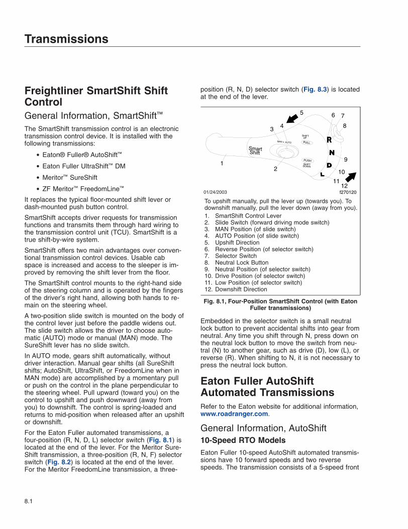
Freightliner SmartShift ShiftControlGeneral Information, SmartShift™
The SmartShift transmission control is an electronictransmission control device. It is installed with thefollowing transmissions:
• Eaton® Fuller® AutoShift™
• Eaton Fuller UltraShift™ DM
• Meritor™ SureShift
• ZF Meritor™ FreedomLine™
It replaces the typical floor-mounted shift lever ordash-mounted push button control.
SmartShift accepts driver requests for transmissionfunctions and transmits them through hard wiring tothe transmission control unit (TCU). SmartShift is atrue shift-by-wire system.
SmartShift offers two main advantages over conven-tional transmission control devices. Usable cabspace is increased and access to the sleeper is im-proved by removing the shift lever from the floor.
The SmartShift control mounts to the right-hand sideof the steering column and is operated by the fingersof the driver’s right hand, allowing both hands to re-main on the steering wheel.
A two-position slide switch is mounted on the body ofthe control lever just before the paddle widens out.The slide switch allows the driver to choose auto-matic (AUTO) mode or manual (MAN) mode. TheSureShift lever has no slide switch.
In AUTO mode, gears shift automatically, withoutdriver interaction. Manual gear shifts (all SureShiftshifts; AutoShift, UltraShift, or FreedomLine when inMAN mode) are accomplished by a momentary pullor push on the control in the plane perpendicular tothe steering wheel. Pull upward (toward you) on thecontrol to upshift and push downward (away fromyou) to downshift. The control is spring-loaded andreturns to mid-position when released after an upshiftor downshift.
For the Eaton Fuller automated transmissions, afour-position (R, N, D, L) selector switch (Fig. 8.1) islocated at the end of the lever. For the Meritor Sure-Shift transmission, a three-position (R, N, F) selectorswitch (Fig. 8.2) is located at the end of the lever.For the Meritor FreedomLine transmission, a three-
position (R, N, D) selector switch (Fig. 8.3) is locatedat the end of the lever.
Embedded in the selector switch is a small neutrallock button to prevent accidental shifts into gear fromneutral. Any time you shift through N, press down onthe neutral lock button to move the switch from neu-tral (N) to another gear, such as drive (D), low (L), orreverse (R). When shifting to N, it is not necessary topress the neutral lock button.
Eaton Fuller AutoShiftAutomated TransmissionsRefer to the Eaton website for additional information,www.roadranger.com.
General Information, AutoShift10-Speed RTO ModelsEaton Fuller 10-speed AutoShift automated transmis-sions have 10 forward speeds and two reversespeeds. The transmission consists of a 5-speed front
01/24/2003
12
3 4
5 6
8
9
10
1112
f270120
7
To upshift manually, pull the lever up (towards you). Todownshift manually, pull the lever down (away from you).1. SmartShift Control Lever2. Slide Switch (forward driving mode switch)3. MAN Position (of slide switch)4. AUTO Position (of slide switch)5. Upshift Direction6. Reverse Position (of selector switch)7. Selector Switch8. Neutral Lock Button9. Neutral Position (of selector switch)10. Drive Position (of selector switch)11. Low Position (of selector switch)12. Downshift Direction
Fig. 8.1, Four-Position SmartShift Control (with EatonFuller transmissions)
Transmissions
8.1

section and a 2-speed rear section. The driver mustuse the clutch to start and stop the vehicle.
The driver does not need to break torque or increaseor decrease engine speed to synchronize the shift.The transmission signals the engine controller whento break torque and the engine controller automati-cally increases or decreases engine speed. Whenengine speed is correct, the transmission engagesthe next gear and signals the engine controller toresume operation.
The AutoShift system consists of the following com-ponents:
• The Gear Display Module (Fig. 8.4) mountedon the dashboard indicates the current gearposition or transmission status. The displayalso flashes the next gear to be engaged whilethe transmission is in Neutral during a gearchange.
• The Driver Command Console (DCC) replacesthe shift lever and controls the transmission’sshift patterns.
11/23/99
PUSH
PULL
Smart Shift
1
f270081
SHIFT DOWN
SHIFT UP
2
4
3
5
6
7
To upshift, pull the lever up (towards you). To downshift,pull the lever down (away from you).1. SmartShift Control Lever2. Upshift Direction3. Reverse Position (of selector switch)4. Selector Switch5. Neutral Position (of selector switch)6. Forward Position (of selector switch)7. Downshift Direction
Fig. 8.2, Three-Position SmartShift Lever (with MeritorSureShift)
06/03/99 f270065
RN
D
12
3
4
5 67
1. Upshift (in manual mode, pull upward)2. Steering Wheel3. Reverse Position4. Neutral Position5. Drive Position6. Downshift (in manual mode, push downward)7. Steering Column
Fig. 8.3, SmartShift Control Operation (FreedomLinecontrol, showing only R, N, D positions)
1
4
5
SOLID
SOLID
FLASHING
02/17/98 f270062
3
2
SOLID
A
BA. Gear Display Module B. Module Detail1. Current Gear2. 9th Gear Engaged3. In 9th Gear, Preselected Toward 10th4. Out Of Gear, Waiting For Engine/Transmission rpm
To Synchronize5. 10th Gear Engaged
Fig. 8.4, Gear Display Module
Transmissions
8.2

• The DCC (Fig. 8.5) has indicators for reverse,neutral, and the three forward positions: drive,hold, and low. Service and wait lamps are alsolocated on the console. The gear select handlecontains upshift and downshift buttons and agear select lever detent button.
• The shifter performs shifts at the front portionof the transmission. It preselects the shift toneutral and completes the gear change afterdriver input.
• The Electronic Control Unit (ECU) includes twocontrollers: a transmission ECU and a systemECU. The transmission ECU controls all trans-mission shift functions and the system ECUmanages all vehicle interfaces for transmissionshift functions.
• An electronic range valve, controlled by thetransmission ECU, is used to perform rangeshifts.
Operation, SmartShift With EatonFuller AutoShift
WARNINGIf the engine cranks in any gear other than neu-tral, have the vehicle serviced immediately. If thevehicle is started in gear it will suddenly move
forward or backward, which could result in per-sonal injury and damage to property and thetransmission.
Automatic and Manual ModesA two-position slide switch (forward driving modeswitch) is located near the end of the control(Fig. 8.1). The switch positions are labelled MAN(manual shift mode) and AUTO (automatic drivemode).
NOTE: In automatic drive mode, upshifts anddownshifts require no driver interaction. Movethe selector switch to the drive (D) position, dis-engage the clutch to engage the gear selected,engage the clutch and drive the vehicle. Inmanual shift mode, upshifts and downshifts re-quire either a pull upward or push downward onthe control.
Driver Message CenterGear information is presented to the driver via thelevel III ICU (ICU2M) Driver Message Center. In au-tomatic drive mode, the number of the forward gearcurrently engaged appears continually on the mes-sage display screen when in drive (D). In manualshift mode, the current gear is displayed until a newgear is requested. When neutral (N) is engaged, "N"will appear on the message display screen. Whenreverse (R) is engaged on 10- or 18-speed AutoShifttransmissions, either "RL" or "RH" will appear on themessage display screen. AutoShift transmissions withfewer speeds do not have a dual range reverse gearand "R" will appear when reverse is engaged.
IMPORTANT: The information shown on themessage display screen indicates the state ofthe transmission only, not the state of theSmartShift control.
Start-Up1. With the parking brake applied, press the clutch
all the way down to the floor.
2. Start the engine.
3. Check to make sure the transmission is in neu-tral.
4. With the transmission in neutral, release theclutch.
N
D
H
SERVICE
WAIT
HOLD
R
L2
3
4
5
A
B
02/16/98
1
f270064
A. Console Top ViewB. Select Handle Side View1. Indicator Lamps2. Gear Position
Indicator
3. Upshift Button4. Detent Button5. Downshift Button
Fig. 8.5, Enhanced Driver Command Console (DCC)
Transmissions
8.3

NOTE: This allows the speed sensor on theinput shaft to get a reading.
5. Press down on the clutch again and release theparking brake.
6. Select the desired starting gear.
7. Release the clutch.
Reverse1. To engage reverse (R), slide the selector switch
upward to the next position above the Neutralposition and disengage the clutch.
NOTE: AutoShift 10- and 18-speed transmis-sions have a dual-range reverse. Reverse low(RL) is the default reverse gear.
2. Select reverse high (RH) by pulling upward onthe control.
NOTE: Reverse may be engaged below a pro-grammable forward speed in order to rock thevehicle. If reverse is selected above the pro-grammed forward speed, an audible warning willsound and a message indicating that the gear isnot available will appear on the message dis-play screen.
Neutral PositionSelect neutral (N) by moving the selector switch tothe "N" position.
NOTE: Neutral is always available during opera-tion. When in neutral, upshift and downshift re-quests are ignored. If the mode selector switchis moved from neutral to drive (D) while the ve-hicle is moving, the transmission will shift into agear causing the engine to go to a high torquelevel, under the engine’s rated torque.
Selecting a Starting Gear1. In automatic mode, select drive (D) by sliding the
selector switch downward to the next positionbelow the neutral position.
2. Disengage the clutch to engage the gear se-lected. Engage the clutch and drive the vehicle.
NOTE: To select a starting gear other than thedefault starting gear, either pull upward or pushdownward on the control while the vehicle is
stopped and in drive (either manual or auto-matic mode). Each pull upward on the controlincreases the starting gear by one gear, but nohigher than fourth gear. The number of the gearselected will flash on the message displayscreen until the driver engages the clutch. Thisgear will be stored in memory as the defaultstarting gear until either a different starting gearis selected by the driver or the engine is shutdown. The transmission may also be pro-grammed so that it is not possible to select astarting gear other than the preprogrammed de-fault starting gear.
Upshifting
NOTE: With the transmission in drive (D) in theautomatic mode, upshifts require no driver inter-action.
1. With the transmission in drive in the manualmode, request an upshift by pulling upward onthe control. If the requested gear is available, thetransmission will upshift.
NOTE: A single, momentary pull upward on thecontrol selects the next higher gear when it isavailable. Two consecutive, momentary upwardpulls will cause a skip shift when the next twohigher gears are available and conditions areright.
2. To skip shift, move the control two times in lessthan 1/2 second. The number of the gear en-gaged will appear on the message displayscreen.
NOTE: The Eaton Fuller AutoShift 18-speedtransmission is able to perform triple upshiftswhen the next three higher gears are availableand conditions are right. To triple shift this trans-mission, move the control three times in lessthan 1/2 second.
If a requested gear is not available, an audiblewarning will sound and the message displayscreen will indicate that the gear is not avail-able. An unavailable requested upshift is notstored in memory. The upshift must be re-quested again.
Transmissions
8.4
Downshifting
NOTE: With the transmission in drive (D) in theautomatic mode, downshifts require no driverinteraction.
1. With the transmission in drive in the manualmode, request a downshift by pushing downwardon the control. If the requested gear is available,the transmission will downshift.
NOTE: A single, momentary push downward onthe control selects the next lower gear when it isavailable. Two consecutive, momentary down-ward pushes will cause a skip shift, when thenext two lower gears are available and condi-tions are right.
2. To skip shift, move the control two times in lessthan 1/2 second. The number of the gear en-gaged will appear on the message displayscreen.
NOTE: The Eaton Fuller AutoShift 18-speedtransmission is able to perform triple downshiftswhen the next three lower gears are availableand conditions are right. To triple shift this trans-mission, move the control three times in lessthan 1/2 second.
If a requested gear is not available, an audiblewarning will sound and the message displayscreen will indicate that the requested gear isnot available. Unlike upshifting, an unavailablerequested downshift is stored in memory andthe shift will be made when the gear is avail-able. The time limit for this memory is a pro-grammable parameter.
Low Gear OperationUse low (L) when descending steep hills and usingcompression braking. Engine speed will be increasedby 200 rpms and shift points will be offset by 200rpm. The efficiency of the exhaust brake will be maxi-mized.
Using the ClutchUse the clutch to start and stop the vehicle.
Operation, AutoShift (withoutSmartShift)
WARNINGIf the engine cranks in any gear other than neu-tral, have the vehicle serviced immediately. If thevehicle is started in gear it will suddenly moveforward or backward, which could result in per-sonal injury and damage to property and thetransmission.
Start-Up1. With the parking brake applied, press the clutch
all the way down to the floor.
2. Start the engine.
3. Check to make sure the transmission is in neu-tral.
4. With the transmission in neutral, release theclutch.
NOTE: This allows the speed sensor on theinput shaft to get a reading.
5. Press down on the clutch again and release theparking brake.
6. Select the desired starting gear.
7. Release the clutch.
Reverse
NOTE: To drive in reverse, first depress theclutch.
1. Move the gear select lever to the "R" position.
2. Select either LO or HI reverse by depressing ei-ther the downshift or upshift button (Fig. 8.5) onthe gear select handle (if equipped).
3. Release the clutch.
NOTE: The clutch must be used for starting andstopping.
Driving in the "D" Mode
NOTE: The drive mode is used for normal driv-ing conditions.
1. Fully depress the clutch.
Transmissions
8.5
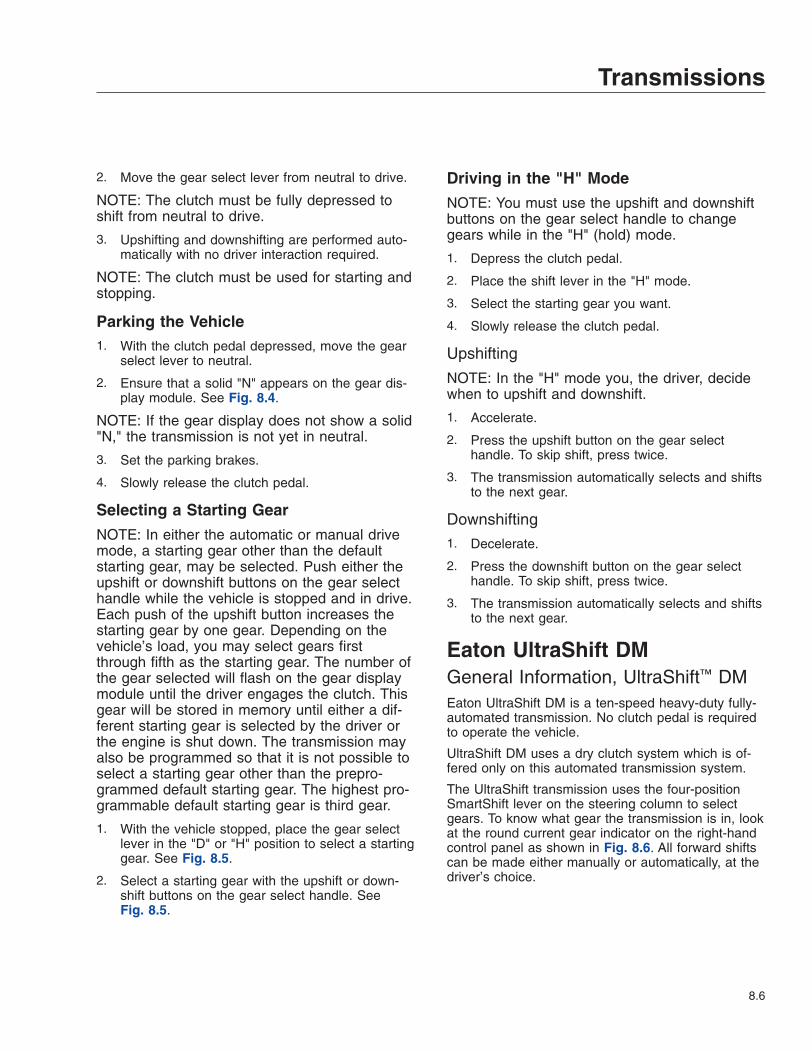
2. Move the gear select lever from neutral to drive.
NOTE: The clutch must be fully depressed toshift from neutral to drive.
3. Upshifting and downshifting are performed auto-matically with no driver interaction required.
NOTE: The clutch must be used for starting andstopping.
Parking the Vehicle1. With the clutch pedal depressed, move the gear
select lever to neutral.
2. Ensure that a solid "N" appears on the gear dis-play module. See Fig. 8.4.
NOTE: If the gear display does not show a solid"N," the transmission is not yet in neutral.
3. Set the parking brakes.
4. Slowly release the clutch pedal.
Selecting a Starting Gear
NOTE: In either the automatic or manual drivemode, a starting gear other than the defaultstarting gear, may be selected. Push either theupshift or downshift buttons on the gear selecthandle while the vehicle is stopped and in drive.Each push of the upshift button increases thestarting gear by one gear. Depending on thevehicle’s load, you may select gears firstthrough fifth as the starting gear. The number ofthe gear selected will flash on the gear displaymodule until the driver engages the clutch. Thisgear will be stored in memory until either a dif-ferent starting gear is selected by the driver orthe engine is shut down. The transmission mayalso be programmed so that it is not possible toselect a starting gear other than the prepro-grammed default starting gear. The highest pro-grammable default starting gear is third gear.
1. With the vehicle stopped, place the gear selectlever in the "D" or "H" position to select a startinggear. See Fig. 8.5.
2. Select a starting gear with the upshift or down-shift buttons on the gear select handle. SeeFig. 8.5.
Driving in the "H" Mode
NOTE: You must use the upshift and downshiftbuttons on the gear select handle to changegears while in the "H" (hold) mode.
1. Depress the clutch pedal.
2. Place the shift lever in the "H" mode.
3. Select the starting gear you want.
4. Slowly release the clutch pedal.
Upshifting
NOTE: In the "H" mode you, the driver, decidewhen to upshift and downshift.
1. Accelerate.
2. Press the upshift button on the gear selecthandle. To skip shift, press twice.
3. The transmission automatically selects and shiftsto the next gear.
Downshifting1. Decelerate.
2. Press the downshift button on the gear selecthandle. To skip shift, press twice.
3. The transmission automatically selects and shiftsto the next gear.
Eaton UltraShift DMGeneral Information, UltraShift™ DMEaton UltraShift DM is a ten-speed heavy-duty fully-automated transmission. No clutch pedal is requiredto operate the vehicle.
UltraShift DM uses a dry clutch system which is of-fered only on this automated transmission system.
The UltraShift transmission uses the four-positionSmartShift lever on the steering column to selectgears. To know what gear the transmission is in, lookat the round current gear indicator on the right-handcontrol panel as shown in Fig. 8.6. All forward shiftscan be made either manually or automatically, at thedriver’s choice.
Transmissions
8.6

Operation, UltraShift DMPower Up1. With the parking brake set, select neutral (N) by
moving the selector switch to the N position.
2. With the transmission in neutral, turn on the igni-tion switch. The "CHECK TRANS" and "TRANSTEMP" telltale lights come on and go out again(bulb check). See Fig. 8.7.
3. After the ignition is turned on, the current gearindicator shows the dot display, arranged in asquare pattern. All dots in the pattern should lightup, without gaps or spaces. See Fig. 8.8.
4. Wait for the current gear indicator to show a solid"N." When the "N" is solid, rather than flashing,the UltraShift DM TCU is powered up. Start theengine and apply the service brake.
5. Select drive (D) by pressing in the neutral lockbutton and moving the selector switch downwardto the position below neutral. Release the park-ing brake. The gear is displayed on the currentgear indicator.
NOTE: When D is selected, the transmissionstarts up in the default starting gear.
6. On a level grade, release the service brake andpress down on the throttle pedal to allow the ve-hicle to move forward. The vehicle will not moveuntil the pedal is depressed.
WARNINGWhen starting or stopping on hills and grades,use extra care to prevent the vehicle from rollingback. A rollback accident could cause death, seri-ous personal injury, or property damage.
7. Prevent the vehicle from rolling backwards whenstopped on a hill or grade, or when the vehicle isstarting from a stop on a hill or grade.
12/22/2003 f270079a
1
2
To know what gear the transmission is in, look at thecurrent gear indicator.1. Current Gear Indicator2. SmartShift Control
Fig. 8.6, Shift Controls and Indicators, UltraShiftTransmissions
BRAKE
CHECKTRANS
f610677
1
TRANSTEMP
10/27/2003
2
1. "CHECK TRANS" Light2. "TRANS TEMP" Light
Fig. 8.7, Telltale Lights
10/13/2003 f610678
Fig. 8.8, Power Up Dot Display
Transmissions
8.7

7.1 To start from a full stop on hill or grade,quickly move your foot from the brakepedal and press firmly on the throttlepedal.
On steep hills, set the parking brake andrelease it only when there is enough en-gine power to prevent rollback.
7.2 To stop on a hill or grade, press and holdthe brake pedal to keep the vehicle frommoving. On steep hills, set the parkingbrake and chock the tires, front and/orrear.
On steep hills, set the parking brake andchock the tires, front and/or rear. Neverhold a hill with the throttle pedal. This willcause the clutch to overheat.
Power Down1. Apply the service brakes.
2. Select neutral (N) by pressing in the neutral lockbutton and moving the selector switch to N.When the "N" on the current gear indicator issolid, rather than flashing, the UltraShift DM TCUis ready to power down.
3. With the transmission in neutral, set the parkingbrake.
4. Turn off the ignition key and shut down the en-gine.
Automatic and Manual ModesThe SmartShift control has a slide switch located onthe body of the control lever just before the paddlewidens out. See Fig. 8.9. The slide switch controlsthe forward driving mode, automatic or manual.
To change mode at any time, move the slide switchin the desired direction. This allows the driver to re-spond flexibly to a wide range of driving conditions,such as blind corners, tight curves, and steep hills.
IMPORTANT: Whatever the mode, it is alwayspossible to shift manually by moving the leverup or down as needed. When the engine speedis within 75 revolutions per minute (rpm) of theload-based shift point for an automatic shift, theUltraShift DM TCU will advance the shift.
In either mode, the gear indicator displays the cur-rent gear. See Fig. 8.10.
At the start of a shift, the current gear continues todisplay until the transmission has been pulled intoneutral. At this point, as the transmission is synchro-nizing for the new (target) gear, the gear indicatorflashes the number of the new gear.
When the shift is complete, the new gear displayssolid, without flashing.
01/21/2004 f270079c
1 2
3
1. Slide Switch (controls forward driving mode)2. Selector Switch (controls gear selection)3. Neutral Lock Button (prevents accidental shift into
gear)
Fig. 8.9, Switches, UltraShift Transmissions
10/13/2003 f610680
NOTE: The gear indicator displays the current gear. Inthis example, it displays first gear.
Fig. 8.10, Current Gear Display
Transmissions
8.8

Automatic Mode (AUTO)In automatic drive mode (AUTO), upshifts and down-shifts are made by the transmission without driverintervention. Press in the neutral lock button, movethe selector switch to drive (D), and press down onthe throttle pedal. The transmission will shift auto-matically.
If driving conditions require, it is still possible to re-quest a manual shift. The transmission will make theshift if the engine speed is within 75 rpm of the load-based shift point for that gear.
If the driver presses down on the throttle pedal aftera manual downshift in automatic mode, the transmis-sion will upshift again if the UltraShift DM TCU re-quires it.
Manual Mode (MAN)In manual drive mode (MAN), upshifts and down-shifts are made by the driver:
• To shift up, pull the lever up (towards you).
• To shift down, push the lever down (away fromyou).
The system will hold the current gear until the driverrequests a shift. In downhill situations in particular,the driver must be alert to vehicle speed by down-shifting and/or using the service brakes as needed.
A shift request will still be refused if the selected gearwould cause engine overspeed or excessive lugging.
Selecting GearsReverseReverse (R) is at the upper end of the four-positionselector switch located at the end of the SmartShiftcontrol lever. To select R, press in the neutral lockbutton and move the selector switch upward to theposition above neutral.
UltraShift DM has two reverse gears, reverse lowand reverse high. To manually shift between them,use the shift lever as described for MAN mode.There is no AUTO mode for reverse.
When reverse low is selected, the letter "R" displayson the current gear indicator. When reverse high isselected, the letter "H" displays on the current gearindicator. See Fig. 8.11.
IMPORTANT: Under normal conditions, do notselect reverse with the vehicle moving forward.
The vehicle must be moving at less than two milesper hour (3 km/h) before selecting reverse. If reverseis selected when the vehicle is moving faster, an au-dible warning will sound and continue sounding atthree-second intervals until the control lever is re-turned to the "D" position or the vehicle slows to theproper speed.
If necessary to rock the vehicle, use the selectorswitch to shift back and forth at low speed betweenreverse and drive.
Neutral
IMPORTANT: Always start the engine with thetransmission in neutral, the parking brake set,and the service brakes applied.
Neutral (N) is directly below R on the four-positionselector switch located at the end of the SmartShiftcontrol lever. To select N, press in the neutral lockbutton and move the selector switch to the positionbelow R. When neutral is selected, the letter "N" dis-plays on the current gear indicator. See Fig. 8.12.
WARNINGDo not coast in neutral. Coasting in neutral cancause an accident, possibly resulting in severepersonal injury or death.
Neutral is always available during operation, what-ever the vehicle speed. When in neutral, requests to
10/14/2003 f610681
Fig. 8.11, Reverse Gear Display
Transmissions
8.9

upshift or downshift are ignored. If the selector switchis moved from neutral to drive while the vehicle ismoving, the transmission will shift into a gear withinthe engine’s operating torque range.
Before shutting down the engine, return the selectorswitch to N. When the ignition is turned off, the trans-mission will reset to neutral in a few minutes regard-less of the position of the shift lever.
DriveDrive (D) is directly below N on the four-position se-lector switch located at the end of the SmartShiftcontrol lever. To select D, press in the neutral lockbutton and move the selector switch to the positionbelow N. When drive is selected, the number of thecurrently selected forward gear (1 through 10) dis-plays on the gear indicator. See Fig. 8.10.
When in drive, requests to upshift or downshift areenabled. Either manual or automatic mode can beselected on the slide switch.
More than one starting gear is available. To changethe starting gear, press the brake pedal and select Dwith the vehicle stopped. The current gear indicatorwill display the starting gear. Move the shift lever upor down until the desired starting gear is displayed.
The UltraShift DM TCU adapts to the working condi-tions of each vehicle and its driver. After power up ora load change, it needs to learn the new conditions.While learning, it may hold a gear too long beforeupshifting. Start the upshift manually. It may takethree or four shifts before UltraShift succeeds in
learning the new load-based shift points, but afterthat it will handle the shifting automatically.
LowLow (L) is located at the lower end of the four-position selector switch located at the end of theSmartShift control lever. To select L, press in theneutral lock button and move the selector switch tothe position below D.
When in low, the current gear is maintained. Re-quests to upshift are not enabled.
IMPORTANT: If the engine is approaching over-speed, the UltraShift DM TCU will override thecurrent gear setting and upshift to prevent en-gine damage.
To enhance engine braking, downshifts are per-formed at higher rpm than normal.
If L is selected from neutral while stopped, the ve-hicle starts up in first gear and stays there until theengine approaches overspeed.
UpshiftingTo request an upshift with the transmission in drive,pull the control lever up (towards you). If the gear isavailable, the transmission upshifts and the new geardisplays on the gear indicator. No skip shifts areavailable while upshifting.
No upshifts are available in low, except to preventengine overspeed.
If the transmission does not upshift quickly enoughafter power-up or a load change, begin the shiftmanually. The UltraShift DM TCU will learn the newload-based shift conditions after three or four shifts.
If the gear requested is unavailable, a tone willsound. An unavailable request to upshift is not storedin memory. The upshift must be requested again.
Downshifting
NOTE: The driver can manually downshift atany time, even when the slide switch is set toAUTO mode.
To request a downshift with the transmission in driveor low, push the control lever down (away from you).If the gear is available, the transmission downshiftsand the new gear displays on the gear indicator. Skipshifts are available while downshifting.
10/13/2003 f610679
Fig. 8.12, Neutral Display
Transmissions
8.10

For best engine braking, select low while moving. Inlow, downshifts are performed at higher rpm than indrive.
IMPORTANT: If the engine is approaching over-speed, the UltraShift DM TCU will override thecurrent gear setting and upshift to prevent en-gine damage.
If the gear requested is unavailable, a tone willsound. An unavailable request to downshift is notstored in memory. The downshift must be requestedagain.
When coasting to a stop, the UltraShift DM TCUdoes not finish the downshift until the driver pressesdown on the throttle pedal again.
IMPORTANT: A downshift request can neverresult in a shift into neutral, even if the vehicle isin the drive position in the lowest possible gear.
Before starting down a hill, slow down. Downshift toa speed that you can control without hard pressureon the service brakes.
Before entering a curve, slow down to a safe speed.Downshift if necessary. This lets you use somepower through the curve to help the vehicle be morestable on the turn. It also allows you to regain speedfaster as you come out of the curve.
Ultrashift DiagnosticsClutch Protection FaultExcessive clutch slippage creates heat and reducesthe life of the clutch. These are some conditionswhich lead to clutch abuse:
• Using the throttle to hold the vehicle on agrade
• Starting the vehicle in too high a gear
• Overloading the vehicle
• Using high idle with the vehicle in gear
The UltraShift DM TCU is programmed to preventclutch abuse. When the clutch overheats, the follow-ing alerts take place:
• The "TRANS TEMP" light comes on
• The current gear indicator displays "CA"
• A warning tone sounds at one second intervals
The alerts continue until the clutch cools, the throttleis released, or the clutch is fully engaged.
System ProblemIn the event of a problem, do the following steps:
1. Note the driving conditions at the time the prob-lem occurred.
2. Record the status of the transmission at the timeof the problem (AUTO or MAN mode, gear set-ting R, N, D, or L, current gear, engine speed,etc.)
3. Reset the system, using the procedure below.
Reset ProcedureTransmission operation can sometimes be restoredby doing the following reset procedure:
1. Stop the vehicle when it is safe to do so. Set theparking brake.
2. Place the selector switch in neutral and turn offthe ignition.
3. Check all harness connectors as described inChapter 11.
4. Wait at least two minutes with the engine shutdown.
5. Restart the engine.
If the problem continues, contact an authorizedFreightliner or Eaton service facility.
Locked In GearIf the transmission becomes locked in gear, a dash(-) will appear on the current gear indicator when thevehicle is restarted during the reset procedure.
NOTE: If the transmission becomes locked ingear while the vehicle is moving, increasedbraking effort may be required to stop the ve-hicle.
If the current gear indicator displays a dash duringpower-up with the selector switch in neutral, do thefollowing steps:
1. Make sure the parking brake is set.
2. Turn off the ignition and wait at least two min-utes.
3. Apply brakes.
Transmissions
8.11

4. With the service brakes applied, release theparking brake.
5. Make sure the selector switch is in neutral andturn on the ignition key. Do not attempt to startthe engine at this time.
6. If necessary to get the transmission to shift intoneutral, release the pressure on the brake pedalslightly.
7. Once the UltraShift DM TCU reaches neutral, asolid "N" will appear on the current gear indicatorand the vehicle will start. Make sure the servicebrakes are applied and the parking brake is set.
If the current gear indicator continues to display adash, contact an authorized Freighliner or Eaton ser-vice facility.
Meritor SureShiftRefer to the Meritor website for additional informa-tion, www.arvinmeritor.com.
Operation, Meritor SureShiftManual ModeThere is no slide switch on the Meritor SureShift con-trol. Only the manual mode is available.
Driver Message CenterGear information is presented to the driver via thelevel III ICU Driver Message Center. The current for-ward numerical gear is displayed until a new gear isrequested. During the shifting process, the letters"SH" appear until the shift is completed. Then, thenewly engaged numerical gear is displayed. Whenneutral (N) is engaged, "N" will appear on the mes-sage display screen. When reverse (R) is engaged,"RL" will appear on the message display screen.
IMPORTANT: The information shown on themessage display screen indicates the state ofthe transmission only, not the state of theSmartShift control.
Neutral PositionNeutral (N) is in the center of the three positions ofthe selector switch at the end of the control. Selectneutral by sliding the mode selector switch to thecenter position.
NOTE: Neutral is always available during opera-tion. When in neutral, upshift and downshift re-quests are ignored. If the mode selector switchis moved from neutral to forward (F) while thevehicle is moving, the transmission will shift intoa gear causing the engine to go to a high torquelevel, under the engine’s rated torque.
Selecting a Starting Gear1. Select forward (F) by sliding the selector switch
downward to the next position below the neutralposition.
NOTE: When forward is selected, the transmis-sion controller is signaled to engage the defaultstarting gear.
2. Select a different starting gear by pulling upwardon the control while the vehicle is stopped and inForward, before disengaging the clutch to en-gage the selected gear.
NOTE: Each pull upward on the control in-creases the starting gear by one gear, but nohigher than fourth gear. The number of the se-lected starting gear is displayed for one secondand then the signal to disengage the clutch "CL"is displayed. Disengaging the clutch will engagethe selected starting gear, which will now bestored in memory as the default starting gear.However, when the transmission controller isreinitialized at the beginning of another powercycle, the starting gear will default to the origi-nally preprogrammed starting gear. The trans-mission may also be programmed so that it isnot possible to select a starting gear other thanthe preprogrammed default starting gear.
UpshiftingWith the transmission in forward (F), request an up-shift by pulling upward on the control. If the re-quested gear is available, the transmission will up-shift.
NOTE: If a requested gear is not available, anaudible warning will sound and a message willappear on the message display screen advisingthat the gear is not available. An unavailablerequested upshift is not stored in memory. The
Transmissions
8.12

upshift must be requested again. All shift re-quests with the clutch disengaged, while thevehicle is in motion, will be ignored. Skip shiftingis not available with the Meritor version ofSmartShift.
DownshiftingWith the transmission in forward (F), request a down-shift by pushing downward on the control. If the re-quested gear is available, the transmission will down-shift.
NOTE: If a requested gear is not available, anaudible warning will sound and a message willappear on the message display screen advisingthat the gear is not available. An unavailablerequested downshift is not stored in memory.The downshift must be requested again. All shiftrequests with the clutch disengaged, while thevehicle is in motion, will be ignored. Skip shiftingis not available with the Meritor version ofSmartShift. While in the forward position in thelowest available gear, a downshift request willnot cause a shift into neutral.
Reverse1. To select reverse (R), slide the mode selector
switch upward to the next position above theNeutral position.
NOTE: Reverse low (RL) is the default reversegear.
2. Select reverse high (RH) by pulling upward onthe control before disengaging the clutch.
NOTE: It is not possible to shift between lowrange reverse and high range reverse with thevehicle in motion. If reverse is selected abovethe minimum detectable speed in Forward, anaudible warning will sound and a warning mes-sage will appear on the message displayscreen.
Using the ClutchUse the clutch to start and stop the vehicle.
ZF Meritor FreedomLineAutomated TransmissionsRefer to the Meritor website for additional informa-tion, www.arvinmeritor.com.
General Information, FreedomLineThe ZF Meritor™ FreedomLine is a fully-automatedmanual transmission that features only an accelera-tor and brake pedal in the cab. Clutch actuation isfully automated. On Freightliner vehicles, it will beoperated by a custom version of the SmartShift™controller. On Century Class S/T vehicles, dash mes-sages will appear on the SmartDash™ (ICU2M).
This transmission requires an additional 10-liter airreservoir. After any transmission service, it will benecessary to charge this tank with air before the ve-hicle can be operated.
Operation, FreedomLine1. With the parking brake engaged and/or the brake
pedal pressed down, select neutral (N) by press-ing in the safety release and moving the selectorswitch to the center position. See Fig. 8.13.
2. With the transmission in neutral, start the engine.Allow the air pressure to build to 100 psi (689kPa) to ensure clutch engagement before movingthe vehicle.
3. With air pressure built up, select drive (D) bypressing in the safety release and moving theselector switch downward to the position belowneutral. Release the parking brake and/or pedal.
NOTE: When D is selected, the transmissioncontroller starts up in the default starting gear.
4. Press down on the accelerator pedal to allow thevehicle to move forward. The vehicle will notmove until the pedal is depressed.
WARNINGA vehicle equipped with the FreedomLine fully-automated transmission can roll backwards whenstopped on a hill or grade, or when the vehicle isstarting from a stop on a hill or grade. This canresult in serious personal injury or property dam-age.
Transmissions
8.13

5. To stop on a hill or grade, press and hold thebrake pedal to keep the vehicle from moving.
6. To start from a full stop on hill or grade, quicklymove your foot from the brake pedal and pressfirmly on the accelerator pedal.
Automatic and Manual ModesThe SmartShift selector has a slide switch located onthe body of the control lever just before the paddlewidens out. The slide switch controls the forwarddriving mode, automatic or manual.
In automatic drive mode, upshifts and downshifts aremade by the transmission without driver intervention.Press in the safety release, move the selector switchto drive (D), and press down on the acceleratorpedal. On the driver message center display, the firstcharacter is a special character to indicate automaticmode.
In manual drive mode, upshifts and downshifts aremade by the driver:
• To shift up, pull the lever up (towards you).
• To shift down, push the lever down (away fromyou).
On the driver message center display, the first char-acter is blank to indicate manual mode.
NOTE: Automatic shifting is possible only in for-ward gear. When the selector switch is in re-verse (R), all shifts are done manually, regard-less of the position of the slide switch.
Gear PositionsNeutralNeutral (N) is in the center of the three-position se-lector switch located at the end of the SmartShiftcontrol lever. To select neutral, press in the safetyrelease and move the selector switch to the centerposition.
Neutral is always available during operation. When inneutral, requests to upshift or downshift are ignored.If the selector switch is moved from neutral to drivewhile the vehicle is moving, the transmission will shiftinto a gear within the engine’s operating torquerange.
ReverseTo select reverse (R), press in the safety release andmove the selector switch upward to the positionabove neutral.
NOTE: When the selector switch is in reverse(R), all shifts are done manually, regardless ofthe position of the slide switch.
The vehicle must come to a complete stop beforeselecting reverse. If reverse is selected with the ve-hicle moving, an audible warning will sound. Oncethe vehicle has come to a complete stop, reverse lowcan be engaged.
There are two reverse gears. Reverse low (RL) is thedefault reverse gear. To select reverse high (RH),pull the control lever up (towards you). You can shiftbetween RL and RH "on the fly," without stoppingfirst.
Upshifting
NOTE: A request to upshift or downshift canonly be accepted in the manual mode.
11/11/2002
12
3 4
5 67
9
10
11f270080
8
To upshift manually, pull the lever up (towards you). Todownshift manually, push the lever down (away fromyou).1. SmartShift Control Lever2. Slide Switch (forward driving mode switch)3. MAN Position (on slide switch)4. AUTO Position (on slide switch)5. Upshift Direction6. Reverse Position (on selector switch)7. Selector Switch8. Safety Release9. Neutral Position (on selector switch)10. Drive Position (on selector switch)11. Downshift Direction
Fig. 8.13, SmartShift Controller (FreedomLine customversion)
Transmissions
8.14

With the transmission in drive, to request an upshift,pull the control lever up (towards you). If the gear isavailable, the transmission will upshift.
An unavailable request to upshift is not stored inmemory. The upshift must be requested again. Skipshifting in manual mode is not available with the ZFMeritor version of SmartShift.
Downshifting
NOTE: A request to upshift or downshift canonly be accepted in the manual mode.
With the transmission in drive, to request a down-shift, push the control lever down (away from you). Ifthe gear is available, the transmission will downshift.
An unavailable request to downshift is not stored inmemory. The downshift must be requested again.Skip shifting in manual mode is not available with theZF Meritor version of SmartShift.
IMPORTANT: A downshift request can neverresult in a shift into neutral, even if the vehicle isin the drive position in the lowest possible gear.
Selecting a Non-Default Starting Gear
NOTE: For the clutch to engage, pressure in theprimary air system must be at least 100 psi (689kPa).
1. Select drive (D) by pressing in the safety releaseand moving the selector switch downward to theposition below neutral.
2. Select manual mode (MAN) by moving the two-position slide switch towards the steering columnuntil it is in the manual position.
3. To increase the starting gear, pull the lever up(towards you). To decrease the starting gear,push the lever down (away from you).
4. Select automatic mode (AUTO), if desired, bymoving the two-position slide switch away fromthe steering column until it is in the automatic po-sition.
Driver Message CenterOn the Century Class S/T, the gear is displayed onthe driver display screen in the SmartDash™ (ICU2M)message center. See Fig. 8.14.
The first character of the display is either blank, toindicate the transmission is in manual mode, or anup-and-down arrow to indicate the transmission is inautomatic mode.
NOTE: Pre-production vehicles will have a smallnumeric "10" in place of the up-and-down arrowwhen in automatic mode.
The next two characters indicate the current gear.For forward drive gears, this appears as a two-digitnumber (Examples: "03, "11"). For reverse, two let-ters appear, either "RL" for low reverse (the default),or "RH" for high reverse. For neutral, a single letter"N" appears.
Eaton Fuller Range-ShiftTransmissionsRefer to the Eaton website for additional information,www.roadranger.com.
General Information, Eaton Range-ShiftTo operate a range-shift transmission, move the shiftlever through all of the low gear positions, then acti-vate the range switch. This provides an additional setof ratios in the high range. Using the same shift leverpositions as used in low range, move the shift leverthrough each position as before. On some models,the initial low gear is used only in low range.
Eaton Fuller Range-Shift transmissions are not syn-chronized in the front section, but the range sectionis synchronized to prevent grinding gears duringrange shifts.
IMPORTANT: Not all lever positions are used ineach range and the shift patterns vary between
07
1
03/21/2002 f600996c
1. Driver Display Screen
Fig. 8.14, SmartDash Display
Transmissions
8.15

transmissions. Be sure to read the shift patterndecal on the dash for the operating instructionsfor the specific transmission installed in your ve-hicle.
9-Speed RT, RTO, and RTX ModelsEaton Fuller 9-speed transmissions have a 5-speedfront section, and a 2-speed rear range section. Onthe RT-8609 and all "A" and "B" ratio transmissions,the low gear is used only as a starting ratio. On "R"ratio transmissions, the high gear is used only as thetop gear. The remaining gear positions of the abovetransmissions are used once in the low range andonce in the high range. See Fig. 8.15 for the shiftpatterns.
NOTE: The 3rd/7th and 4th/8th shift positions inthe RT (direct ratio) and RTX-B (overdrive ratio)transmissions are opposite of the RTO (over-drive ratio) transmissions. The RTX-R ratiotransmissions have the 1st/5th shift positionswhere LOW is in the A and B ratio transmis-sions. The top gear in the RTX-R ratio transmis-sions is called 9th gear.
10-Speed RT, RTO, RTLO, and RTXModelsEaton Fuller 10-speed transmissions have ten selec-tive, evenly-spaced forward ratios. Each transmissionhas a 5-speed front section, and a 2-speed rearrange section. The ten forward speeds are obtainedby twice using a 5-speed shift pattern: the first timein low range, the second time in high range. SeeFig. 8.16 for the shift patterns.
NOTE: The 4th/9th and the 5th/10th shift posi-tions in the RT (direct ratio) and RTX (overdriveratio) transmissions are directly opposite in theRTO (overdrive ratio) transmissions.
Operation, Eaton Range-Shift1. When operating off-highway, or under adverse
conditions, always use low gear (if so equipped)when starting to move the vehicle.
When operating on-highway, with no load, orunder ideal conditions, use 1st gear when start-ing to move the vehicle (except when equippedwith a 9-speed RTO transmission, then alwaysstart in low gear).
For all conditions, use the highest gear that isstill low enough to start the vehicle moving withengine idling, and without slipping the clutchexcessively.
2. Use the clutch brake to stop gear rotation whenshifting into low (or 1st) or reverse when the ve-hicle is stationary. The clutch brake is actuatedby depressing the clutch pedal all the way to thefloor.
For normal upshifts and downshifts, only a partialdisengagement of the clutch is necessary tobreak engine torque.
3. Do not make range shifts with the vehicle movingin reverse gear.
4. Never attempt to move the range preselectionlever with the gear shift lever in neutral while thevehicle is moving. Preselection with the rangepreselection lever must be made prior to movingthe shift lever out of gear into neutral.
5. Do not shift from high range to low range at highvehicle speeds.
6. Double-clutch between all upshifts and down-shifts.
7. After your shifting ability improves, you may wantto skip some of the ratios. This may be doneonly when operating conditions permit, depend-ing on the load, grade, and road speed.
Upshifting1. Position the gear shift lever in neutral. Start the
engine, and bring the air system pressure up to100 to 120 psi (689 to 827 kPa).
2. Position the range preselection lever down, intolow range.
3. Depress the clutch pedal to the floor; shift intolow or 1st gear (Table 8.1), then engage theclutch, with the engine at or near idle speed, tostart the vehicle moving. Accelerate to 80 per-cent of engine governed speed.
4. Shift progressively upward from low or 1st gear,to the top gear in low range (Table 8.1), double-clutching between shifts, and accelerating to 80percent of engine governed speed.
Transmissions
8.16

CAUTIONTo prevent damage to the range section syn-chros, make sure the range preselection lever isin high range before moving the shift lever toneutral. Leave the shift lever in neutral longenough to be sure the range section has shifted.
5. While in the top gear of the low-range shift pat-tern, and ready for the next upshift, flip the rangepreselection lever up into high range. Double-clutch through neutral, and shift into the bottomgear in high range (Table 8.1). As the shift leverpasses through neutral, the transmission will au-tomatically shift from low range to high range.
Eaton Fuller Shift Progressions
TRANS.MODEL
LOW RANGE HIGHRANGEOff-Highway On-Highway
8-SpeedDirect(RT)
1
2
3
4
f260321
R
1
2
3
4
f260321
R 7
6 8
5
f260320
R
9-SpeedDirect orOverdrive
(RT orRTX)
1
2
3
4
f260322
R
LOW
1
2
3
4
f260323
R
7
6 8
5
f260324
R
9-SpeedDirect
(RTX-P)
2
3
4
1
f260325
R
2
3
4
1
f260325
R
8
7 9
6
f260326
R
5
9-SpeedOverdrive
(RTO)
1
2
4
f260327
R
3LOW
1
2
4
f260327
R
3LOW
8
6 7
5
f260328
R
10-SpeedDirect orOverdrive
(RT orRTX)
2
3
4
1
f260329
R
5
2
3
4
1
f260329
R
5
9
8 10
7
f260330
R
6
10-SpeedOverdrive
(RTO)
2
3
5
1
f260331
R
4
2
3
5
1
f260331
R
4
10
8 9
7
f260332
R
6
Table 8.1, Eaton Fuller Shift Progressions
6. With the transmission in high range, shift pro-gressively upward through each of the high
1
4
5
86
73
21
4
5
86
73
2
1 45 8
6 732 9
A B C
D
E
03/13/96 f260027a
N N N
A. All RT and RTX-B TransmissionsB. All RTO TransmissionsC. All RTX-R Transmissions
D. High RangeE. Low Range
Fig. 8.15, Eaton Fuller 9-Speed Transmission Shift Patterns
4
N
72
9
61
83
105
72
105
61
83
94
RHi
LoRHi
Lo
A B
C
D
03/13/96 f260043a
N
A. All RT and RTX TransmissionsB. All RTO TransmissionsC. High RangeD. Low Range
Fig. 8.16, Eaton Fuller 10-Speed Transmissions ShiftPatterns
Transmissions
8.17

range gears (Table 8.1), double-clutching be-tween shifts.
Downshifting1. With the transmission in high range, shift pro-
gressively downward to the bottom gear in highrange, double-clutching between shifts.
2. When in the bottom gear of the high-range shiftpattern, and ready for the next downshift, pushthe range preselection lever down into low range.Double-clutch through neutral, and shift into thetop gear of the low-range shift pattern. As theshift lever passes through neutral, the transmis-sion will automatically shift from high range tolow range.
3. With the transmission in low range, downshiftthrough the low range gears as conditions re-quire.
IMPORTANT: Never use the clutch brake whendownshifting, or as a brake to slow the vehicle.
Eaton Fuller Splitter andRange-Shift TransmissionsRefer to the Eaton website for additional information,www.roadranger.com.
General Information, Eaton Splitterand Range-Shift13-Speed RTLO ModelsEaton Fuller 13-speed transmissions have thirteenforward speeds and two reverse speeds. Each trans-mission has a 5-speed front section, and a 3-speedauxiliary section. The auxiliary section contains low-and high-range ratios, plus an overdrive splitter gear.See Fig. 8.17 for the shift pattern.
All of the 13 speeds are controlled with one shiftlever. A range preselection lever and a splitter controlbutton are built into the shift knob. The range prese-lection lever controls range selection and the splittercontrol button (located on the side of the shift knob)controls gear splits.
Low gear in the front section is used only as a start-ing ratio. The remaining four forward positions areused once in the low range and once in the highrange. However, each of the four high range gearpositions can be split with the underdrive ratio (RT
models), or overdrive ratio (RTO models) of the split-ter gear. Ratios cannot be split while the transmis-sion is in low range.
18-Speed RTO ModelsEaton Fuller 18-speed transmissions have eighteenforward speeds and four reverse, consisting of a5-speed front section and a 3-speed auxiliary sec-tion. The auxiliary section contains low and highrange ratios, plus an overdrive splitter gear. SeeFig. 8.18 for the shift pattern.
One ratio in the front section (low) is used as a start-ing ratio; it is never used when the transmission is inhigh range.
R1 3
2 4LOW
Dir OD5 5
Dir OD
Dir OD Dir OD
7 7
6 6 8 8
Hi
Lo
A
B
C D
1
03/13/96 f260044a
N
A. High RangeB. Low Range
C. Overdrive (forward)D. Direct Drive (rearward)
1. Splitter Control Button
Fig. 8.17, Eaton Fuller 13-Speed Transmission ShiftPattern
N
R 1Dir
5Dir
5OD1
OD3
Dir
7Dir
7OD3
OD
2Dir
6Dir
6OD2
OD4
Dir
8Dir
8OD4
ODLOWDir
LOWOD
A
B
C D
1
03/13/96 f260157a
A. High RangeB. Low Range
C. Overdrive (forward)D. Direct Drive (rearward)
1. Splitter Control Button
Fig. 8.18, Eaton Fuller 18-Speed Transmission ShiftPattern
Transmissions
8.18
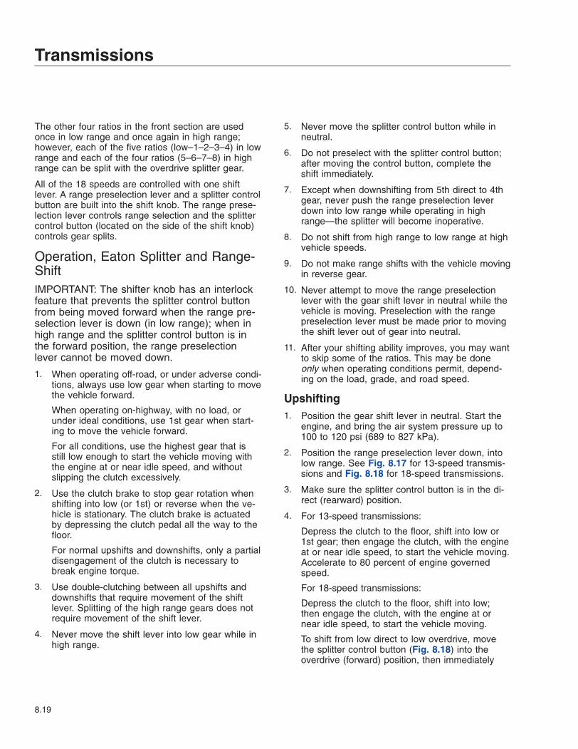
The other four ratios in the front section are usedonce in low range and once again in high range;however, each of the five ratios (low–1–2–3–4) in lowrange and each of the four ratios (5–6–7–8) in highrange can be split with the overdrive splitter gear.
All of the 18 speeds are controlled with one shiftlever. A range preselection lever and a splitter controlbutton are built into the shift knob. The range prese-lection lever controls range selection and the splittercontrol button (located on the side of the shift knob)controls gear splits.
Operation, Eaton Splitter and Range-ShiftIMPORTANT: The shifter knob has an interlockfeature that prevents the splitter control buttonfrom being moved forward when the range pre-selection lever is down (in low range); when inhigh range and the splitter control button is inthe forward position, the range preselectionlever cannot be moved down.
1. When operating off-road, or under adverse condi-tions, always use low gear when starting to movethe vehicle forward.
When operating on-highway, with no load, orunder ideal conditions, use 1st gear when start-ing to move the vehicle forward.
For all conditions, use the highest gear that isstill low enough to start the vehicle moving withthe engine at or near idle speed, and withoutslipping the clutch excessively.
2. Use the clutch brake to stop gear rotation whenshifting into low (or 1st) or reverse when the ve-hicle is stationary. The clutch brake is actuatedby depressing the clutch pedal all the way to thefloor.
For normal upshifts and downshifts, only a partialdisengagement of the clutch is necessary tobreak engine torque.
3. Use double-clutching between all upshifts anddownshifts that require movement of the shiftlever. Splitting of the high range gears does notrequire movement of the shift lever.
4. Never move the shift lever into low gear while inhigh range.
5. Never move the splitter control button while inneutral.
6. Do not preselect with the splitter control button;after moving the control button, complete theshift immediately.
7. Except when downshifting from 5th direct to 4thgear, never push the range preselection leverdown into low range while operating in highrange—the splitter will become inoperative.
8. Do not shift from high range to low range at highvehicle speeds.
9. Do not make range shifts with the vehicle movingin reverse gear.
10. Never attempt to move the range preselectionlever with the gear shift lever in neutral while thevehicle is moving. Preselection with the rangepreselection lever must be made prior to movingthe shift lever out of gear into neutral.
11. After your shifting ability improves, you may wantto skip some of the ratios. This may be doneonly when operating conditions permit, depend-ing on the load, grade, and road speed.
Upshifting1. Position the gear shift lever in neutral. Start the
engine, and bring the air system pressure up to100 to 120 psi (689 to 827 kPa).
2. Position the range preselection lever down, intolow range. See Fig. 8.17 for 13-speed transmis-sions and Fig. 8.18 for 18-speed transmissions.
3. Make sure the splitter control button is in the di-rect (rearward) position.
4. For 13-speed transmissions:
Depress the clutch to the floor, shift into low or1st gear; then engage the clutch, with the engineat or near idle speed, to start the vehicle moving.Accelerate to 80 percent of engine governedspeed.
For 18-speed transmissions:
Depress the clutch to the floor, shift into low;then engage the clutch, with the engine at ornear idle speed, to start the vehicle moving.
To shift from low direct to low overdrive, movethe splitter control button (Fig. 8.18) into theoverdrive (forward) position, then immediately
Transmissions
8.19

release the accelerator. Press and release theclutch pedal. After releasing the clutch, acceler-ate again.
5. For 13-speed transmissions:
Shift upward from low to 1st gear, 2nd, etc. until4th gear, double-clutching between shifts, andaccelerating to 80 percent of engine governedspeed. See Fig. 8.17.
For 18-speed transmissions:
Shift upward from low overdrive to 1st direct byfirst moving the splitter control button into thedirect (rearward) position (Fig. 8.18). Move theshift lever, double-clutching, to the 1st gear posi-tion.
Continue upshifting through the shift pattern.Double-clutch during lever shifts (1st to 2nd to3rd to 4th); single-clutch during split shifts (1stdirect to 1st overdrive, etc.).
6. When in 4th gear (13-speed transmissions) or4th overdrive (18-speed transmissions) andready to shift up to 5th gear, use the range shiftlever as follows:
For 13-speed transmissions:
While in 4th gear, pull the range shift preselec-tion lever up, into high range. The transmissionwill automatically shift from low to high range asthe shift lever passes through neutral. Then, dis-engage the clutch; double-clutch through neutral;move the shift lever to 5th gear; engage theclutch, and accelerate the engine.
For 18-speed transmissions:
While in 4th overdrive, pull the range shift prese-lection lever up, into high range. The transmis-sion will automatically shift from low to highrange as the shift lever passes through neutral.
Move the shift lever, double-clutching, to the 5thgear position. Just before making final clutch en-gagement, move the splitter control button to thedirect (rearward) position; then engage the clutchand accelerate. Do not move the control buttonwhile the shift lever is in neutral.
7. Shift up through the high range gears as follows:
For 13-speed transmissions:
To shift from 5th direct to 5th overdrive, move thesplitter control button (Fig. 8.17) into the over-drive (forward) position, then immediately release
the accelerator. Press and release the clutchpedal. After releasing the clutch, accelerateagain.
Continue upshifting through the shift pattern.Double-clutch during lever shifts (6th to 7th to8th); single-clutch during split shifts (6th direct to6th overdrive, etc.).
For 18-speed transmissions:
To shift from 5th direct to 5th overdrive, move thesplitter control button (Fig. 8.18) into the over-drive (forward) position, then immediately releasethe accelerator. Press and release the clutchpedal. After releasing the clutch, accelerateagain.
Continue upshifting through the shift pattern.Double-clutch during lever shifts (6th to 7th to8th); single-clutch during split shifts (6th direct to6th overdrive, etc.).
Downshifting1. Downshift from 8th overdrive to 8th direct without
moving the shift lever. Flip the splitter control but-ton to the direct (rearward) position, then imme-diately release the accelerator, and disengagethe clutch. Engage the clutch, and accelerate theengine only after the transmission has shifted.
2. Start the downshift from 8th direct to 7th over-drive by flipping the splitter control button to theoverdrive (forward) position; then, immediatelydouble-clutch through neutral, moving the shiftlever from 8th to 7th gear.
3. Shift downward through each of the high rangegears, alternating the procedures in steps 1 and2, above, until reaching 5th direct.
4. While in 5th direct and ready for the downshift to4th (13-speed transmissions) or 4th overdrive(18-speed transmissions), push the range prese-lection lever down. Then, double-clutch throughneutral and move the shift lever to the 4th gearposition. On 18-speed transmissions, move thesplitter control button to the overdrive (forward)position beforeengaging the clutch. Do not movethe control button while the shift lever is in neu-tral.
5. Continue downshifting from 4th to 1st as follows:
For 13-speed transmissions:
Transmissions
8.20

Downshift through the low range gears as condi-tions require.
For 18-speed transmissions:
Continue downshifting from 4th overdrive to 4thdirect, then 4th direct to 3rd overdrive, 3rd over-drive to 3rd direct, etc. Single-clutch when splitshifting (direct to overdrive, overdrive to direct).Double-clutch when making lever shifts (4th to3rd, 3rd to 2nd, etc.).
IMPORTANT: Never use the clutch brake whendownshifting, or as a brake to slow the vehicle.
Eaton Fuller Deep-ReductionTransmissionsRefer to the Eaton website for additional information,www.roadranger.com.
General Information, Deep Reduction10-Speed RT, RTO and RTX ModelsEaton Fuller 10-speed deep-reduction transmissionshave a 5-speed front section, and a 2-speed rear-range section, with a deep reduction gear. The low-low, deep reduction gear is used only when operatingunder adverse conditions. Low gear in the front sec-tion is used only for rough, off-highway conditions, asa starting ratio. The remaining four forward positionsare used once in the low range and once in the highrange. See Fig. 8.19 for the shift pattern.
NOTE: The 3rd/7th and 4th/8th shift positions inthe RT and RTX-LL transmissions are oppositeof the RTO-LL transmissions.
15-Speed RT, RTO, and RTX ModelsEaton Fuller 15-speed deep-reduction transmissionshave a 5-speed front section, and a 2-speed rear-range section. They also have five additional deepreduction ratios. The 5-speed front section, and thelow and high range sections provide ten evenly andprogressively spaced forward speeds. The five deepreduction ratios are also evenly and progressivelyspaced; however, they do overlap the low range ra-tios, and should be used only when operating underadverse conditions. See Fig. 8.20 for the shift pat-terns.
NOTE: The 4th/9th, and the 5th/10th shift posi-tions in the RT (direct ratio) and RTX (overdrive
ratio) transmissions are directly opposite in theRTO (overdrive ratio) transmissions.
Operation, Deep ReductionIMPORTANT: The shifter knob has an interlockfeature that prevents the deep reduction buttonfrom being moved forward when the range pre-selection lever is up (in high range); when in lowrange and the deep reduction button is in theforward position, the range preselection levercannot be moved up.
1. For all driving conditions, use the highest gearthat is still low enough to start the vehicle movingwith the engine idling, and without slipping theclutch excessively.
2. Use the clutch brake to stop gear rotation whenshifting into low-low, low-1st (whichever is usedas a starting ratio) or reverse, when the vehicleis stationary. The clutch brake is actuated by de-pressing the clutch pedal all the way to the floor.
For normal upshifts and downshifts, only a partialdisengagement of the clutch is necessary tobreak engine torque.
3. Double-clutch between all upshifts and down-shifts.
4. Never move the shift lever into low gear while inhigh range.
1 45 8
6 732
1 35 7
26 8
4
A B
C
D
E F
1
03/13/96 f260026a
N N
A. All RTO TransmissionsB. All RT and RTX TransmissionsC. High RangeD. Low RangeE. Deep Reduction IN (forward)F. Deep Reduction OUT (rearward)1. Deep Reduction Button
Fig. 8.19, Eaton Fuller 10-Speed RT, RTO and RTXModel Transmissions Shift Patterns
Transmissions
8.21
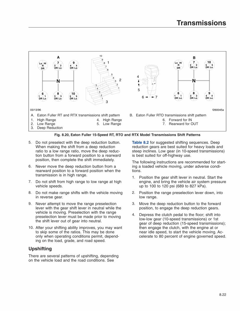
5. Do not preselect with the deep reduction button.When making the shift from a deep reductionratio to a low range ratio, move the deep reduc-tion button from a forward position to a rearwardposition, then complete the shift immediately.
6. Never move the deep reduction button from arearward position to a forward position when thetransmission is in high range.
7. Do not shift from high range to low range at highvehicle speeds.
8. Do not make range shifts with the vehicle movingin reverse gear.
9. Never attempt to move the range preselectionlever with the gear shift lever in neutral while thevehicle is moving. Preselection with the rangepreselection lever must be made prior to movingthe shift lever out of gear into neutral.
10. After your shifting ability improves, you may wantto skip some of the ratios. This may be doneonly when operating conditions permit, depend-ing on the load, grade, and road speed.
UpshiftingThere are several patterns of upshifting, dependingon the vehicle load and the road conditions. See
Table 8.2 for suggested shifting sequences. Deepreduction gears are best suited for heavy loads andsteep inclines. Low gear (in 10-speed transmissions)is best suited for off-highway use.
The following instructions are recommended for start-ing a loaded vehicle moving, under adverse condi-tions.
1. Position the gear shift lever in neutral. Start theengine, and bring the vehicle air system pressureup to 100 to 120 psi (689 to 827 kPa).
2. Position the range preselection lever down, intolow range.
3. Move the deep reduction button to the forwardposition, to engage the deep reduction gears.
4. Depress the clutch pedal to the floor; shift intolow-low gear (10-speed transmissions) or 1stgear of deep reduction (15-speed transmissions);then engage the clutch, with the engine at ornear idle speed, to start the vehicle moving. Ac-celerate to 80 percent of engine governed speed.
7 9
6 8 10
7 10
6 8 9
R Lo Hi
DR DR Lo 2 2
DR Lo
DR Lo DR Lo DR Lo
4 4
1 1 3 3 5 5
R Lo Hi
DR DR Lo DR Lo
DR Lo DR Lo DR Lo
2 2 5 5
1 1 3 3 4 4
1
1
2
2
3
3
4
4
5
5
6 7
8 9
10
1
2
3
4
5
6 7
03/13/96 f260045a
N N
A B
A. Eaton Fuller RT and RTX transmissions shift pattern B. Eaton Fuller RTO transmissions shift pattern1. High Range2. Low Range3. Deep Reduction
4. High Range5. Low Range
6. Forward for IN7. Rearward for OUT
Fig. 8.20, Eaton Fuller 15-Speed RT, RTO and RTX Model Transmissions Shift Patterns
Transmissions
8.22

Eaton Fuller Shift Progressions
TRANSMISSIONMODEL
DEEP REDUCTION LOW RANGE HIGH RANGEAdverse Conditions
OnlyOff-Highway and
Adverse ConditionsOn-Highway and Ideal
ConditionsAll Conditions
10-Speed RTO
R
f260335
LOW−LOW
R 1
2 3
4
LOW
f260333
R 1
2 3
4
f260336
R
6 7
f260337
5 8
10-Speed RTX
R
f260335
LOW−LOW
R 1
2 4
3
f260338
LOW
R 1
2 4
3
f260339
R
6 8
f260340
5 7
15-Speed RTO
f260341
R
2 5
31DRDRDR
DR DR
4
f260342
R
LoLo Lo
LoLo
1
2
4
5
3
f260343
R
1
2
3 4
5
Lo
LoLo
LoLo
R
6
7
8 9
10
f260344
15-Speed RT and RTX
f260345
R
DR DR
DRDRDR1
2
3
4
5
f260346
R
Lo Lo Lo
LoLo42
3 51
f260347
R
Lo Lo Lo
LoLo2
3 5
4
1
R
6
7
8 10
f260348
6
Table 8.2, Eaton Fuller Shift Progressions
5. For 10-speed transmissions:
When ready for the next upshift, move the deepreduction button rearward, then break the torqueon the gears by momentarily releasing the accel-erator or depressing the clutch pedal. Do notmove the shift lever.
For 15-speed transmissions:
Shift upward from 1st gear of deep reduction to5th gear of deep reduction, double-clutching be-tween shifts and accelerating to 80 percent ofengine governed speed. See Table 8.2.
When ready for the next upshift, move the deepreduction button from the forward position to therearward position, then double-clutch throughneutral, and move the shift lever to the 4th gearposition in the low range.
6. Shift upward from low gear (10-speed transmis-sions) or 4th gear (15-speed transmissions), tothe top gear in low range (see Table 8.2),double-clutching between shifts, and acceleratingto 80 percent of engine governed speed.
7. While in the top gear of the low-range shift pat-tern, and ready for the next upshift, flip the rangepreselection lever up into high range. Double-
clutch through neutral, and shift into the bottomgear in high range (see Table 8.2). As the shiftlever passes through neutral, the transmissionwill automatically shift from low range to highrange.
8. With the transmission in high range, shift pro-gressively upward through each of the highrange gears (see Table 8.2), double-clutchingbetween shifts.
Alternate Upshifting Procedures (15-Speed Transmissions Only)The shift from deep reduction to low range can alsobe made from 2nd, 3rd, or 4th gear of deep reduc-tion, but must be made to the next gear lower in thelow range. The shift from 2nd gear of deep reductionto 1st gear in low range (or 3rd gear of deep reduc-tion to 2nd gear in low range, and 4th gear of deepreduction to 3rd gear in low range), is an upshift, andthe same procedure should be followed as thatshown for shifting from 5th gear of deep reduction to4th gear in low range. See the above steps, underthe heading "Upshifting."
Transmissions
8.23

Downshifting1. With the transmission in high range, shift pro-
gressively downward to the bottom gear in highrange, double-clutching between shifts.
2. When in the bottom gear of the high-range shiftpattern, and ready for the next downshift, pushthe range preselection lever down into low range.Double-clutch through neutral, and shift into thetop gear of the low-range shift pattern. As theshift lever passes through neutral, the transmis-sion will automatically shift from high range tolow range.
3. With the transmission in low range, downshiftthrough the low range gears, as conditions re-quire.
IMPORTANT: Never use the clutch brake whendownshifting, or as a brake to slow the vehicle.
Meritor Range-ShiftTransmissionsRefer to the Meritor website for additional informa-tion, www.arvinmeritor.com.
General Information, Meritor Range-Shift9-Speed RM, RMO, and RMX ModelsMeritor 9-speed transmissions have a 5-speed frontsection, and a 2-speed auxiliary section. The lowgear in the front sections of the "A" and "B" ratiotransmissions is used only as a starting ratio. Thehigh gear in the front section of the "R" ratio trans-missions is used only as the top gear. The remaininggear positions of the above transmissions are usedonce in the low range and once in the high range.See Fig. 8.21 for the shift patterns.
NOTE: The 3rd/7th and 4th/8th shift positions inthe RM and RMX (direct ratio) are opposite ofthe RMO (overdrive ratio) transmissions. TheRMX-R ratio transmissions have the 1st/5th shiftpositions where low is in the A and B ratio trans-missions. The top gear in the RMX-R ratiotransmissions is called 9th gear.
10-Speed RM and RMX ModelsMeritor 10-speed transmissions have ten evenly-spaced forward ratios. Each transmission consists ofa 5-speed front section, and a 2-speed auxiliary sec-tion. The ten forward speeds are obtained by twiceusing a 5-speed shift pattern: the first time in lowrange; the second time in high range. See Fig. 8.22for the shift pattern.
Operation, Meritor Range-ShiftReverseTo drive in reverse, push the range selector leverdown to put the transmission in the low range. Pushthe clutch pedal to the bottom of travel so the clutchbrake slows the transmission for initial gear engage-ment. Holding the clutch pedal at the bottom oftravel, shift into reverse.
Slowly release the clutch pedal to move the vehiclein reverse.
Upshifting1. To drive forward, make sure the vehicle is com-
pletely stopped and the range selector lever ispushed down to put the transmission in the lowrange.
Push the clutch pedal to the bottom of travel sothe clutch brake slows the transmission for initialgear engagement; holding the clutch pedal at thebottom of travel, shift into low.
2. Slowly release the clutch pedal to begin movingthe vehicle forward.
3. To upshift into 1st gear, only partial depression ofthe clutch pedal is needed. Do not push theclutch pedal all the way to the floor and engagethe clutch brake; instead, partially depress theclutch pedal, and move the shift lever into neu-tral.
4. Release the clutch, and allow the engine to de-celerate until the road speed and the engine rpmmatch.
5. Partially depress the clutch pedal, and move theshift lever into first gear.
6. Double-clutch and continue upshifting until youreach the top gear in the low range, 4th gear in9-speed models and 5th gear in 10-speedmodels. See Table 8.3.
Transmissions
8.24

7. To upshift into high range—with the transmissionstill in the highest low-range gear—move therange selector lever up to put the transmissioninto high range, then partially depress the clutchpedal and move the shift lever into neutral. Asthe shift lever passes through neutral, the trans-mission will automatically shift from low range tohigh range.
8. Release the clutch pedal, and let the engine slowuntil the road speed and engine rpm match.
9. Partially depress the clutch pedal, and move theshift lever into the lowest gear in the high range,5th gear in 9-speed models and 6th gear in 10-speed models.
Meritor Shift Progressions
TRANS.MODEL
LOW RANGE HIGHRANGEOff-Highway On-Highway
9-SpeedDirect orOverdrive
(RM orRMX)
1
2
3
4
f260322
R
LOW
1
2
3
4
f260321
R 7
6 8
5
f260320
R
9-SpeedDirect
(RMX-R)
2
3
4
1
f260325
R
2
3
4
1
f260325
R
8
7 9
6
f260326
R
5
9-SpeedOverdrive
(RMO)
1
2
4
f260327
R
3LOW
1
2
4
f260327
R
3LOW
8
6 7
5
f260328
R
10-SpeedDirect orOverdrive
(RM orRMX)
2
3
4
1
f260329
R
5
2
3
4
1
f260329
R
5
9
8 10
7
f260330
R
6
10-SpeedOverdrive
(RMO)
2
3
5
1
f260331
R
4
2
3
5
1
f260331
R
4
10
8 9
7
f260332
R
6
Table 8.3, Meritor Shift Progressions
10. Double-clutch to continue upshifting.
Downshifting1. With the transmission in high range, shift pro-
gressively downward to the bottom gear in highrange, 5th gear in 9-speed models and 6th gear
1
4
5
86
73
21
4
5
86
73
2
1 45 8
6 732 9
A B C
1
2
03/13/96 f260156a
N N N
A. All RM and RMX Transmissions B. All RMO Transmissions C. All RMX-R Transmissions1. High Range 2. Low Range
Fig. 8.21, Meritor 9-Speed RM, RMO and RMX Model Transmissions Shift Patterns
472
9
61
83
105
72
105
61
83
94
A B
C
D
03/13/96 f260155a
NN
A. All RM and RMX TransmissionsB. All RMO TransmissionsC. High RangeD. Low Range
Fig. 8.22, Meritor 10-Speed RM, RMO and RMX ModelTransmissions Shift Patterns
Transmissions
8.25
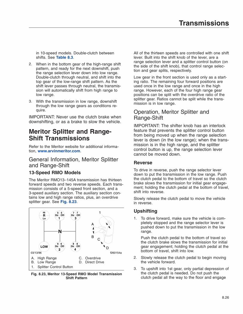
in 10-speed models. Double-clutch betweenshifts. See Table 8.3.
2. When in the bottom gear of the high-range shiftpattern, and ready for the next downshift, pushthe range selection lever down into low range.Double-clutch through neutral, and shift into thetop gear of the low-range shift pattern. As theshift lever passes through neutral, the transmis-sion will automatically shift from high range tolow range.
3. With the transmission in low range, downshiftthrough the low range gears as conditions re-quire.
IMPORTANT: Never use the clutch brake whendownshifting, or as a brake to slow the vehicle.
Meritor Splitter and Range-Shift TransmissionsRefer to the Meritor website for additional informa-tion, www.arvinmeritor.com.
General Information, Meritor Splitterand Range-Shift13-Speed RMO ModelsThe Meritor RMO13–145A transmission has thirteenforward speeds and two reverse speeds. Each trans-mission consists of a 5-speed front section, and a3-speed auxiliary section. The auxiliary section con-tains low and high range ratios, plus, an overdrivesplitter gear. See Fig. 8.23.
All of the thirteen speeds are controlled with one shiftlever. Built into the shift knob of the lever, are arange selection lever and a splitter control button (onthe side of the shift knob), that control range selec-tion and gear splits, respectively.
Low gear in the front section is used only as a start-ing ratio. The remaining four forward positions areused once in the low range and once in the highrange. However, each of the four high range gearpositions can be split with the overdrive ratio of thesplitter gear. Ratios cannot be split while the trans-mission is in low range.
Operation, Meritor Splitter andRange-ShiftIMPORTANT: The shifter knob has an interlockfeature that prevents the splitter control buttonfrom being moved up when the range selectionlever is down (in the low range); when the trans-mission is in the high range, and the splittercontrol button is up, the range selection levercannot be moved down.
ReverseTo drive in reverse, push the range selector leverdown to put the transmission in the low range. Pushthe clutch pedal to the bottom of travel so the clutchbrake slows the transmission for initial gear engage-ment; holding the clutch pedal at the bottom of travel,shift into reverse.
Slowly release the clutch pedal to move the vehiclein reverse.
Upshifting1. To drive forward, make sure the vehicle is com-
pletely stopped and the range selector lever ispushed down to put the transmission in the lowrange.
Push the clutch pedal to the bottom of travel sothe clutch brake slows the transmission for initialgear engagement; holding the clutch pedal at thebottom of travel, shift into low.
2. Slowly release the clutch pedal to begin movingthe vehicle forward.
3. To upshift into 1st gear, only partial depression ofthe clutch pedal is needed. Do not push theclutch pedal all the way to the floor and engage
R1 3
2 4LOW
Dir OD5 5
Dir OD
Dir OD Dir OD
7 7
6 6 8 8
Hi
Lo
A
BC
D
1
03/13/96 f260154a
N
A. High RangeB. Low Range
C. OverdriveD. Direct Drive
1. Splitter Control Button
Fig. 8.23, Meritor 13-Speed RMO Model TransmissionShift Pattern
Transmissions
8.26

the clutch brake; instead, partially depress theclutch pedal, and move the shift lever into neu-tral.
4. Release the clutch pedal, and allow the engineto decelerate until the road speed and the enginerpm match.
5. Partially depress the clutch pedal, and move theshift lever into 1st gear.
6. Double-clutch to continue upshifting until in fourthgear. See Table 8.3.
7. To upshift into high range—with the transmissionstill in 4th gear—push the range selection leverup to put the transmission into high range, thenpartially depress the clutch pedal and move theshift lever into neutral. As the shift lever passesthrough neutral, the transmission will automati-cally shift from low range to high range.
8. Release the clutch pedal, and let the engine slowuntil the road speed and engine rpm match.
9. Partially disengage the clutch, and move the shiftlever into 5th gear.
10. To upshift from 5th gear into 5th overdrive, flipthe splitter control button up to the overdrive po-sition; then, immediately release the accelerator,and press and release the clutch pedal. It is notnecessary to move the shift lever when shiftingfrom direct to overdrive; the transmission willshift when synchronization with the engine’sspeed is reached. Accelerate the engine onlyafter the transmission has shifted.
11. To shift from 5th overdrive to 6th direct, partiallydisengage the clutch, shift into 6th—but beforeengaging the clutch—flip the splitter control but-ton down into the direct drive position; then en-gage the clutch, and accelerate the engine.
Do not move the control button while the shiftlever is in neutral.
12. Shift upward through each of the high rangegears, alternating the procedures in steps 10 and11, above.
Downshifting1. Downshift from 8th overdrive to 8th direct without
moving the shift lever. Flip the splitter control but-ton down to the direct drive position, then imme-diately release the accelerator, and press and
release the clutch pedal. Accelerate the engineonly after the transmission has shifted.
2. To downshift from 8th direct to 7th overdrive, flipthe splitter control button up to the overdrive po-sition, then immediately double-clutch throughneutral, moving the shift lever from 8th to 7thgear.
3. Downshift through each of the high range gearsalternating the procedures in steps 1 and 2,above, until reaching 5th direct.
4. While in 5th direct, and ready for the next down-shift, push the range selection lever down intolow range. Double-clutch through neutral, andshift into 4th gear. See Fig. 8.23. As the shiftlever passes through neutral, the transmissionwill automatically shift from high range to lowrange.
5. With the transmission in low range, downshiftthrough the low range gears as conditions re-quire.
IMPORTANT: Never use the clutch brake whendownshifting, or as a brake to slow the vehicle.
Eaton Fuller AutoSelectAutomated TransmissionsRefer to the Eaton website for additional information,www.roadranger.com.
General Information, AutoSelectEaton Fuller 10-speed AutoSelect automated trans-missions have 10 forward speeds and two reversespeeds. The transmission consists of a 5-speed frontsection and a 2-speed rear section. The driver mustuse the clutch to start and stop the vehicle.
10-Speed RTAO ModelsEaton Fuller 10-speed transmissions have 10 forwardspeeds and two reverse speeds. The transmissionconsists of a 5-speed front section and a 2-speedrear section. The driver must use the clutch to startand stop the vehicle.
When conditions are right for a shift, the transmissionElectronic Control Unit (ECU) notifies the driver witha tone from the Driver Command Console (DCC).See Fig. 8.24. The driver, when ready to shift,breaks torque and the transmission goes to Neutral.
Transmissions
8.27

The driver then either increases or decreases enginespeed to synchronize the shift. When engine speedis correct, the transmission shifts automatically.
The AutoSelect system consists of the following com-ponents.
• The Driver Display Module, or DDM(Fig. 8.25), mounted on the dashboard, indi-cates gear position and the direction enginerpm needs to go for the next gear engage-ment. When the gear select lever is in the "D"position, the display module indicates what thedriver must do to engage the next gear (decel-erate or accelerate) by down and up arrows.When the gear number is solid on the display,that gear is fully engaged. When the gear num-ber is flashing the transmission is either out ofgear, waiting for the engine and transmissionto synchronize, or the next gear engagement isin process.
• The Driver Command Console, or DCC(Fig. 8.24), replaces the shift lever and con-trols the transmission’s shift patterns. Thereare indicators for the three forward positions:drive, hold, and low, plus reverse and neutralpositions. Shift tone volume buttons and ser-vice and wait lamps are also located on theconsole. The gear select handle contains up-
shift and downshift buttons and a gear selectlever detent button.
• The shifter performs shifts at the front portionof the transmission. It preselects the shift toNeutral and completes the gear change afterdriver input.
• The Electronic Control Unit (ECU) consists oftwo controllers: a transmission ECU and a sys-tem ECU. The transmission ECU controls alltransmission shift functions and the systemECU manages all vehicle interfaces for trans-mission shift functions.
• An electronic range valve, controlled by thetransmission ECU, is used to perform rangeshifts.
N
D
H
VOLUME
SERVICE
WAIT
HOLD
R
L
1
2
3
4 6
5
A
B
02/16/98 f270055
A. Console Top ViewB. Select Handle Side View1. Shift Tone Volume
Buttons2. Indicator Lamps3. Gear Position
Indicator
4. Upshift Button5. Detent Button6. Downshift Button
Fig. 8.24, Driver Command Console (DCC)
1
2
3
4
5
6
7
8
SOLID
SOLID
SOLID
FLASHING
FLASHING
F270056
SOLID
SOLID
A
02/25/98B
A. Driver Display ModuleB. Driver Display Module Detail1. Decrease Engine rpm Arrows2. Current Gear Position3. Increase Engine rpm Arrows4. 9th Gear Engaged5. In 9th Gear, Preselected Toward 10th6. Out Of Gear, Waiting For Engine/Transmission rpm
To Synchronize7. Engine/Transmission rpm Synchronized, Gear
Engagement In Process8. 10th Gear Engaged
Fig. 8.25, Driver Display Module (DDM)
Transmissions
8.28
Operation, AutoSelect
WARNINGIf the engine cranks in any gear other than neu-tral, have the vehicle serviced immediately. If thevehicle is started in gear it will suddenly moveforward or backward, which could result in per-sonal injury and damage to property and thetransmission.
Reverse
NOTE: To drive in reverse, first depress theclutch.
1. Move the gear select lever to the "R" position.
2. Select either LO or HI reverse by depressing ei-ther the downshift or upshift button (Fig. 8.24) onthe gear select handle.
3. Release the clutch.
NOTE: The clutch must be used for starting andstopping.
Upshifting ("D" and "H" modes)
NOTE: It is the driver who decides when to up-shift or downshift. When in the "D" (drive) mode,an upcoming shift can be cancelled by puttingthe gear select lever in the "H" mode or byusing the gear select handle buttons. When inthe "H" (hold) mode, it is possible to skip shiftgears if the road and load conditions permit.
1. Accelerate.
NOTE: In the "H" mode, depress the upshift but-ton on the gear select handle. Depress twice toskip shift.
2. An audible tone sounds from the Driver Com-mand Console when the transmission is ready toshift. The arrows on the Driver Display Module(Fig. 8.25) indicate the direction engine rpmneeds to go to synchronize the next shift. Thenext gear is shown on the display. See Fig. 8.25.
3. Release the throttle for the shift to neutral. Theupcoming gear flashes on the display when neu-tral is engaged. The arrows disappear, the cur-rent gear position stops flashing, and engine rpmdecreases and becomes steady.
4. Apply the throttle.
NOTE: If the shift is missed, control enginespeed in the direction indicated by the arrowson the display to synchronize engine rpm withthe transmission’s speed.
Downshifting ("D" and "H" modeswithout an engine load)1. Decelerate.
NOTE: In the "H" mode, depress the downshiftbutton on the gear select handle. Depress twiceto skip shift.
2. An audible tone sounds from the Driver Com-mand Console when the transmission is ready toshift. The arrows on the Driver Display Moduleindicate the direction engine rpm needs to go tosynchronize the next shift. The next gear isshown on the display.
3. Gently roll on the throttle. The upcoming gearflashes on the display when neutral is engaged.The arrows disappear, the current gear positionstops flashing, and engine rpm increases andbecomes steady.
4. Continue decelerating.
NOTE: If the shift is missed, control enginespeed in the direction indicated by the arrowson the display to synchronize engine rpm withthe transmission’s speed.
Downshifting ("D" and "H" modes withan engine load)1. Decelerate.
NOTE: In the "H" mode, depress the downshiftbutton on the gear select handle. Depress twiceto skip shift.
2. An audible tone sounds from the Driver Com-mand Console when the transmission is ready toshift. The arrows on the Driver Display Moduleindicate the direction engine rpm needs to go tosynchronize the next shift. The next gear isshown on the display.
3. Release the throttle. The upcoming gear flasheson the display when neutral is engaged.
Transmissions
8.29

4. Apply throttle to synchronize engine rpm with thetransmission’s speed. The arrows disappear, thecurrent gear position stops flashing, and enginerpm increases and becomes steady.
NOTE: If the shift is missed, control enginespeed in the direction indicated by the arrowson the display to synchronize engine rpm withthe transmission’s speed.
Eaton Fuller Top 2 andLightning Semi-AutomatedTransmissionsRefer to the Eaton website for additional information,www.roadranger.com.
General Information, Top 2 andLightning10-Speed RTL/ RTLO and 13-Speed/18-Speed RTLO ModelsTop 2 and Lightning transmissions have 10 selectiveforward ratios and a 2-speed rear section. Half of the10 speed ratios are shifted with the shift lever andthe other half are shifted by moving the shift button.They shift automatically between the two top gears.See Fig. 8.26 for the Top 2 shift knob, and Fig. 8.27for the Lightning shift knob.
There are three types of shifts used with these trans-missions. Button-only and combination button/levershifts are both full gear changes. The lever-only shiftskips a gear.
• The button-only shift is a gear split shift thatoccurs by moving the shift button.
• The lever-only shift occurs when the shift leveris moved without moving the shift button.
• The combination button/lever shift is a gearratio change that occurs when both the shiftbutton and the shift lever are moved.
The small red service light on the Lightning shiftknob illuminates for a few seconds when the engineis turned on. This confirms that the transmissionelectronics are operating properly.
NOTE: If the service light stays on or flashes, ordoes not illuminate when the engine starts, takethe vehicle to an authorized Freightliner orEaton service facility as soon as possible.
See Fig. 8.28 for the shift patterns for Lightning and10-speed Top 2, 13-speed Top 2, and 18-speed Top2.
Operation, Top 2/Lightning
CAUTIONKeep the transmission in gear at all times whilethe vehicle in motion. Coasting in neutral couldlead to transmission damage.
Fuller
Fuller
09/25/96 f260399
B
A
C
A. Shift ButtonB. Gears 2, 4, 6, 8, 10 when button is forwardC. Gears 1, 3, 5, 7, 9 when button is rearward
Fig. 8.26, Top 2 Shift Knob
09/12/2002 f261190
1
2
1. Shift Button2. Service Light
Fig. 8.27, Lightning Shift Knob
Transmissions
8.30
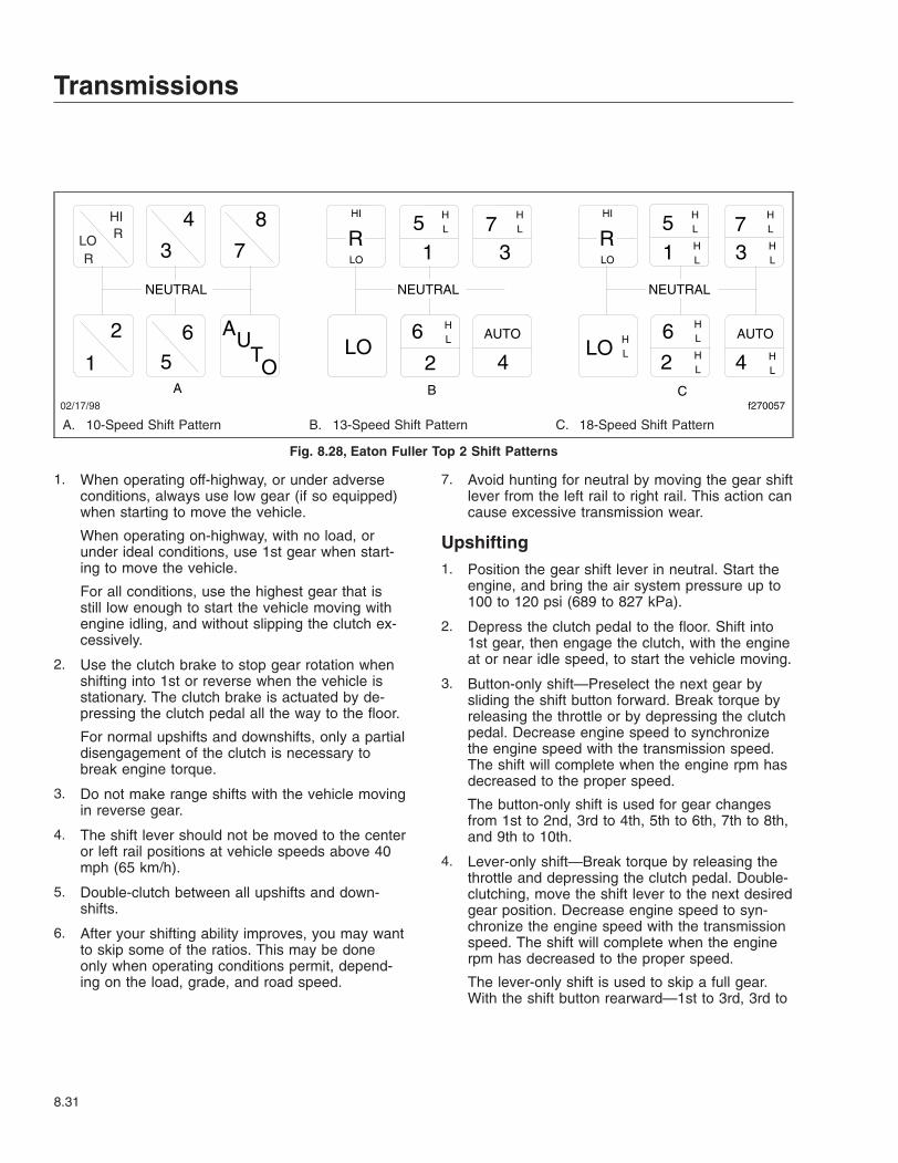
1. When operating off-highway, or under adverseconditions, always use low gear (if so equipped)when starting to move the vehicle.
When operating on-highway, with no load, orunder ideal conditions, use 1st gear when start-ing to move the vehicle.
For all conditions, use the highest gear that isstill low enough to start the vehicle moving withengine idling, and without slipping the clutch ex-cessively.
2. Use the clutch brake to stop gear rotation whenshifting into 1st or reverse when the vehicle isstationary. The clutch brake is actuated by de-pressing the clutch pedal all the way to the floor.
For normal upshifts and downshifts, only a partialdisengagement of the clutch is necessary tobreak engine torque.
3. Do not make range shifts with the vehicle movingin reverse gear.
4. The shift lever should not be moved to the centeror left rail positions at vehicle speeds above 40mph (65 km/h).
5. Double-clutch between all upshifts and down-shifts.
6. After your shifting ability improves, you may wantto skip some of the ratios. This may be doneonly when operating conditions permit, depend-ing on the load, grade, and road speed.
7. Avoid hunting for neutral by moving the gear shiftlever from the left rail to right rail. This action cancause excessive transmission wear.
Upshifting1. Position the gear shift lever in neutral. Start the
engine, and bring the air system pressure up to100 to 120 psi (689 to 827 kPa).
2. Depress the clutch pedal to the floor. Shift into1st gear, then engage the clutch, with the engineat or near idle speed, to start the vehicle moving.
3. Button-only shift—Preselect the next gear bysliding the shift button forward. Break torque byreleasing the throttle or by depressing the clutchpedal. Decrease engine speed to synchronizethe engine speed with the transmission speed.The shift will complete when the engine rpm hasdecreased to the proper speed.
The button-only shift is used for gear changesfrom 1st to 2nd, 3rd to 4th, 5th to 6th, 7th to 8th,and 9th to 10th.
4. Lever-only shift—Break torque by releasing thethrottle and depressing the clutch pedal. Double-clutching, move the shift lever to the next desiredgear position. Decrease engine speed to syn-chronize the engine speed with the transmissionspeed. The shift will complete when the enginerpm has decreased to the proper speed.
The lever-only shift is used to skip a full gear.With the shift button rearward—1st to 3rd, 3rd to
LO
02/17/98
HIR
R
4
3
8
7
1
2 65
AUTO
R5 7
31
6
LO
HI
NEUTRAL NEUTRAL NEUTRAL
AUTO
42LO
AUTO
42LO
6
RLO
HI5 71 3
A B Cf270057
HL
HL
HL
HL
HL
HL H
L HL
HL
HL
HL
A. 10-Speed Shift Pattern B. 13-Speed Shift Pattern C. 18-Speed Shift Pattern
Fig. 8.28, Eaton Fuller Top 2 Shift Patterns
Transmissions
8.31

5th, 5th to 7th, and 7th to 9th. With the shift but-ton forward—2nd to 4th, 4th to 6th, 6th to 8th,8th to 10th.
NOTE: Lever-only shifts skip an entire gear ratioand will require the engine rpm to decreasetwice the amount of a normal shift.
5. Combination button/lever shift—Preselect thenext gear by sliding the shift button rearward.Break torque by releasing the throttle and de-pressing the clutch pedal. Double-clutch andmove the shift lever to the next desired gear po-sition.
The combination button/lever shift is used forgear changes from 2nd to 3rd, 4th to 5th, 6th to7th and 8th to 9th.
Downshifting
CAUTIONDo not attempt a button-only downshift at toohigh an engine speed (generally above 1400rpm). Doing so could result in damage to the en-gine, transmission, and/or driveline.
1. Button-only shift—With the throttle still applied,preselect the next gear by sliding the shift buttonrearward. Break torque by releasing the throttleor by depressing the clutch pedal. Increase en-gine speed to synchronize the engine speed withthe transmission speed. The shift will completewhen the engine rpm has increased to theproper speed.
The button-only shift is used for gear changesfrom 10th to 9th, 8th to 7th, 6th to 5th, 4th to 3rd,and 2nd to 1st.
CAUTIONDo not attempt a lever-only downshift at too highan engine speed (generally above 1000 rpm).Doing so could result in damage to the engine,transmission, and/or driveline.
2. Lever-only shift—Break torque by releasing thethrottle and depressing the clutch pedal. Double-clutching, move the shift lever to the next desiredgear position.
The lever-only shift is used to skip a full gear.With the shift button rearward—9th to 7th, 7th to
5th, 5th to 3rd, and 3rd to 1st. With the shift but-ton forward—10th to 8th, 8th to 6th, 6th to 4thand 4th to 2nd.
IMPORTANT: Never use the clutch brake whendownshifting, or as a brake to slow the vehicle.
CAUTIONDo not attempt a combination button/lever down-shift at too high an engine speed (generallyabove 1400 rpm). Doing so could result in dam-age to the engine, transmission, and/or driveline.
3. Combination button/lever shift—With the throttlestill applied, preselect the next gear by slidingthe shift button forward. Break torque by releas-ing the throttle and depressing the clutch pedal.Double-clutch and move the shift lever to thenext desired gear position.
The combination button/lever shift is used forgear changes from 9th to 8th, 7th to 6th, 5th to4th, and 3rd to 2nd.
Meritor Engine Synchro Shift(ESS) Automated ModelsRefer to the Meritor website for additional informa-tion, www.arvinmeritor.com.
General Information, ESS9–Speed and 10–Speed M, MO, RS, andRSX ModelsMeritor 9-speed and 10-speed automated transmis-sions do not require use of the clutch except to startand stop the vehicle.
NOTE: Meritor M and MO series ESS transmis-sions are available only on vehicles equippedwith either Caterpillar or Cummins electronicengines. Meritor RS and RSX series ESS trans-missions are only available on vehiclesequipped with Detroit Diesel electronic engines.
The ESS system works with the engine fuelcontrol system to automatically synchronize en-gine rpm to road speed during gear changes.Use the clutch only to start and stop the vehicleand to shift into forward or reverse. The HI andLO ranges are automated, so the driver does
Transmissions
8.32

not have to select ranges. A "break torque" fea-ture allows the driver to move the shift lever andtake the transmission out of gear without chang-ing throttle position. Throttle position can bemaintained while braking and downshiftingthrough the gears when stopping the vehicle, aswell as on steep grades.
The major components of the ESS system arethe system switch, shift-intent switch, input andoutput shaft speed sensors, a Neutral positionsensor, and an electro-pneumatic solenoid.
Operation, ESSThe ESS system collects and relays information per-taining to the positions of the shift-intent and systemswitches (Fig. 8.29), transmission input and outputshaft speeds, and shift lever position. The informa-tion is received by the engine Electronic ControlModule (ECM) which signals the fuel control systemto increase or decrease engine rpm to match roadspeed. The ECM also controls HI and LO range se-lection in the auxiliary case on the rear of thetransmission.
The system switch (Fig. 8.29) is the lower switch lo-cated on the driver’s side of the shift handle. It con-trols ESS system operation. When in the down posi-tion, the system is operating and the word ON isvisible on the switch. In the up position, the wordOFF is visible, the system is not operating, and thetransmission can be shifted manually.
The shift-intent switch (Fig. 8.29) is the upper switchon the driver’s side of the shift handle. It has fourpositions and controls upshifting and downshifting bycommunicating to the ECM the driver’s intention ofchanging gears.
NOTE: If the system switch is OFF, use theshift-intent switch to select between ranges.Push the top of the switch (Fig. 8.30) to selectthe HI range on upshifts and the bottom of theswitch (Fig. 8.31) to select the LO range ondownshifts.
WARNINGMake sure that the transmission is in neutral (N)when you start the vehicle. If the vehicle isstarted in gear, it will suddenly move forward orbackward which could result in personal injuryand damage to property and the transmission.
02/17/98 f270058
1
2
1. Shift-Intent Switch 2. System Switch
Fig. 8.29, ESS Shift Handle
02/17/98 f270059A B
A. Press the top portion (engage the first position) ofthe shift-intent switch to begin an upshift.
B. Press the top portion again (engage the secondposition) to break torque.
Fig. 8.30, ESS Upshifting Using the Shift-Intent Switch
02/17/98A B
f270060
A. Press the bottom portion (engage the first position)of the shift-intent switch to begin a downshift.
B. Press the bottom portion again (engage the secondposition) to break torque.
Fig. 8.31, ESS Downshifting Using the Shift-IntentSwitch
Transmissions
8.33
Starting The Vehicle1. Ensure that the shift lever is in the neutral (N)
position.
2. Push the clutch pedal to the bottom of its travelto engage the clutch brake.
3. Start the engine.
4. Slowly release the clutch pedal.
5. Allow the system air to build up to the rangespecified on the gauge.
6. Release the parking brake.
Shifting Into a Starting Gear
CAUTIONAlways use the proper starting gear. Do not shiftinto neutral and coast, as this will result in dam-age to the transmission.
1. Press the system switch down, into the ON posi-tion, to activate the ESS system.
2. Press the top portion of the shift-intent switch.
IMPORTANT: Use the clutch brake only wheninitially engaging a gear with the vehicle stand-ing still.
3. Push the clutch pedal to the bottom of its travelso that the clutch brake stops the transmissioninput shaft from rotating.
4. Move the shift lever and engage a starting gear.
5. Slowly release the clutch pedal.
NOTE: If you do not shift the transmission out ofneutral into a gear within two seconds, the ESSsystem will "time out" and deactivate. The trans-mission returns to manual operation. To reacti-vate the ESS system, press the shift-intentswitch again. See the following procedures forupshifting and downshifting for instructions onhow to use the shift-intent switch.
Upshifting1. To upshift into the next higher gear:
1.1 Press the top portion of the shift-intentswitch.
1.2 Apply pressure with the shift lever towardthe neutral position.
1.3 Press the top portion of the shift-intentswitch again, far enough so that theswitch goes into a second position insidethe body of the shift handle. Then releasethe switch. See Fig. 8.30. This will breaktorque.
1.4 Immediately move the shift lever to theneutral position.
1.5 Allow engine rpm to slow down enough tosynchronize with road speed.
1.6 Move the shift lever to the next highergear.
2. To upshift through the rest of the gears, repeatthe substeps above. Before each upshift, pushthe top of the shift-intent switch into the shifthandle body to break torque. The range shift isautomatic.
3. To skip a gear, press the shift-intent switch intothe shift handle body, while in Neutral, one timefor every gear that is skipped.
Downshifting1. To downshift into the next lower gear.
1.1 Press the bottom portion of the shift-intentswitch.
1.2 Apply pressure with the shift lever towardthe neutral position.
1.3 Press the bottom portion of the shift-intentswitch again, far enough so that theswitch goes into a second position insidethe body of the shift knob. Then releasethe switch. See Fig. 8.31. This will breaktorque.
1.4 Immediately move the shift lever to theneutral position.
1.5 Allow engine rpm to speed up enough tosynchronize with road speed.
1.6 Move the shift lever to the next lowergear.
2. To downshift through the rest of the gears, re-peat the substeps above. Before each downshift,push the bottom of the shift-intent switch into the
Transmissions
8.34

shift handle body to break torque. The rangeshift is automatic.
3. To skip a gear, press the shift-intent switch intothe shift handle, while in neutral, one time forevery gear that is skipped.
Reverse1. Press the system switch on the shift handle so
that it is in the ON position and the ESS systemis activated.
2. Push the clutch pedal to the bottom of its travelso that the clutch brake stops the transmissioninput shaft from rotating.
3. Move the shift lever and engage reverse.
4. Slowly release the clutch pedal and move thevehicle in the reverse direction.
NOTE: If a HI reverse range is required, followthe steps below.
5. Press the system switch on the shift handle sothat it is in the OFF position and the ESS systemis deactivated.
6. Press the top portion of the shift-intent switch toengage the HI range.
7. Push the clutch pedal to the bottom of its travelso that the clutch brake stops the transmissioninput shaft from rotating.
8. Move the shift lever and engage reverse.
9. Slowly release the clutch pedal and move thevehicle in the reverse direction.
See Fig. 8.32 for two ESS 9-speed shift patternsand one ESS 10-speed shift pattern.
Allison AutomaticTransmissionsRefer to the Allison website for additional information,www.allisontransmission.com.
General Information, AllisonHD-series automatic transmissions have six forwardspeeds and one reverse speed. See Fig. 8.33.These transmissions have electronic shift controlsthat can be programmed to allow the use of differentnumbers of geared speeds. For instance, the trans-
mission can be programmed to operate as a4-speed, 5-speed, or 6-speed unit in the "primary"shift mode. If needed, a "secondary" shift mode canbe programmed to provide another shift configurationto optimize vehicle use under different operating con-ditions. To activate a secondary shift mode, or otherspecial function programmed into the electronic con-trol unit (ECU), depress the Mode button. "Mode On"is displayed in the indicator panel just above thepush buttons. A label just above the Mode buttonidentifies the special function.
NOTE: Each time a push button is depressedon the shift selector, a short beep will be heard.This indicates that the ECU has received inputto change operation.
The HD-series transmission system is designed towarn the driver of transmission malfunctions. Thedriver of a vehicle equipped with these transmissionsshould know the extent of the warning system inorder to safely operate the vehicle. See Chapter 2for information on the warning system.
Operation, Allison
CAUTIONThe engine should never be operated for morethan 30 seconds at full throttle with the transmis-sion in gear and the output stalled. Prolongedoperation of this type will overheat the transmis-sion fluid and will result in severe damage to thetransmission.
1. Start the engine, then check the digital displayon the "push button shift selector." Under "Se-lect" at the top of the unit, the display should al-ways show the "primary" shift mode. Under"Monitor," the gear the transmission is in shouldbe displayed.
WARNINGNever shift from neutral (N) to drive (D) or re-verse (R) at engine speeds above idle. The ve-hicle will lurch forward or backward, which couldcause property damage and personal injury.
2. Use reverse (R) to back the vehicle. Completelystop the vehicle before shifting from a forwardgear to reverse or from reverse to forward. Thereis only one reverse gear.
Transmissions
8.35

3. Select drive (D) for all normal driving conditions.The vehicle will start out in 1st gear, and asspeed increases, the transmission will upshiftthrough each gear automatically. As the vehicleslows down, the transmission will downshift tothe correct gear automatically.
The pressure of your foot on the acceleratorpedal influences the automatic shifting. When thepedal is fully depressed, the transmission will
automatically upshift near the governed speed ofthe engine. A partially depressed position of thepedal will cause the upshifts to occur at a lowerengine speed.
4. Occasionally the road, load, or traffic conditionsmake it desirable to restrict the automatic shiftingto a lower range. The lower the gear range, thegreater the engine braking power.
Use the up or down arrow buttons on the shiftselector to reach the desired gear. The "Select"indicator will display your choice, and the "Moni-tor" indicator will show the selected gear once itis reached.
NOTE: In the lower gear ranges, the transmis-sion will not upshift above the highest gear se-lected unless the engine governed speed is ex-ceeded.
5. Use neutral (N) and apply the parking brakewhen the vehicle is parked with the engine run-ning.
CAUTIONDo not allow the vehicle to coast in neutral. Thiscan result in severe transmission damage. Also,no engine braking is available.
02/17/98 f270061
R
R
R
R
R
R
5 7
1 3
3 3 LO 2
2 2
4
4
6 8
6 8
9 7 5
1
7 9
4
5
10 8
1
N N N
6 A B C
A. 9-Speed Shift Pattern with LOGear
B. 9-Speed Shift Pattern C. 10-Speed Shift Pattern
Fig. 8.32, Meritor ESS 9- and 10-Speed Shift Patterns
10/31/94 f600369a
1
2
1. Indicator Panel 2. Mode ID
Fig. 8.33, Allison Push Button Shift Selector
Transmissions
8.36

9
Rear AxlesMeritor Single Drive Axles With Traction Equalizer . . . . . . . . . . . . . . . . . . . . . . . . . . . . . . . . . . . . . . 9.1Meritor Drive Axles With Main Differential Lock . . . . . . . . . . . . . . . . . . . . . . . . . . . . . . . . . . . . . . . . . 9.1Meritor Main Differential Lock Operation . . . . . . . . . . . . . . . . . . . . . . . . . . . . . . . . . . . . . . . . . . . . . . . 9.1Meritor Tandem Drive Axles With Interaxle Differential . . . . . . . . . . . . . . . . . . . . . . . . . . . . . . . . . . . 9.2Meritor Interaxle Differential Lockout Operation . . . . . . . . . . . . . . . . . . . . . . . . . . . . . . . . . . . . . . . . . 9.2Eaton Single Reduction Axles With Controlled Traction Differential . . . . . . . . . . . . . . . . . . . . . . . . . 9.2Eaton 2-Speed Tandem Axles . . . . . . . . . . . . . . . . . . . . . . . . . . . . . . . . . . . . . . . . . . . . . . . . . . . . . . . 9.3Eaton Interaxle Differential Lockout Operation . . . . . . . . . . . . . . . . . . . . . . . . . . . . . . . . . . . . . . . . . . 9.3

Meritor Single Drive AxlesWith Traction EqualizerSome Meritor single drive axles are equipped with atraction equalizer which is a load sensing, self-actuating feature. A traction equalizer provides nor-mal differential action where traction is good. Whenone wheel begins to spin faster than the other, clutchplates in the differential housing automatically en-gage, delivering power to both wheels. There is nooperator control with this feature.
A traction equalizer occasionally tends to slip in ajerking motion, producing irregular intervals of sharpnoises. This generally occurs when the vehicle is op-erating at low speeds on fairly sharp turns. This con-dition, called slip-stick, is corrected by adding a fric-tion modifier to the axle lubricant. This additive tendsto reduce the static coefficient of friction to a valueequal to, or lower than, the sliding coefficient.
See Group 35 of the Century Class Trucks Mainte-nance Manual for additional information on frictionmodifiers and when to add them to axle lubricants.
CAUTIONTire sizes on both rear wheels should be thesame on axles equipped with a traction equalizer.If not, excessive wear may occur in the tractionequalizer.
Meritor Drive Axles With MainDifferential LockThe Meritor main differential lock is a driver-controlled traction device operated from the vehiclecab. A switch allows the driver to lock or unlock thedifferential. An indicator light comes on when the dif-ferential lock is engaged. An optional buzzer can alsobe used to indicate differential lock engagement.
The main differential lock provides maximum tractionunder slippery conditions. When the differential lockis engaged, the clutch collar completely locks thedifferential case, gearing, and axle shafts together,maximizing traction of both wheels and protectingagainst spinout. Under normal traction conditions, donot engage the differential lock. Operate the axlewith differential action between both wheels.
WARNINGBe especially careful when driving under slipperyconditions with the differential locked. Thoughforward traction is improved, the vehicle can stillslip sideways, causing possible loss of vehiclecontrol, personal injury, and property damage.
Meritor Main Differential LockOperationTo lock the main differential and obtain maximumtraction under slippery conditions, move the controlswitch to the lock position.
WARNINGLock the main differential only when the vehicleis standing still or moving less than 25 mph (40km/h). Never lock the main differential when thevehicle is traveling down steep grades or whenthe wheels are slipping. This could damage thedifferential or lead to loss of vehicle control,causing personal injury and property damage.
NOTE: On some vehicles, the differential locksystem is connected through the low speedrange of the transmission. If this system is used,the transmission must be in the low speedrange for the differential to fully lock.
If the vehicle is moving, maintain a constant vehiclespeed while engaging the differential lock. Briefly letup on the accelerator to relieve torque on the gear-ing, allowing the differential to fully lock. The indica-tor light should come on and the buzzer shouldsound on vehicles so equipped. When the differentialis fully locked, the turning radius will increase be-cause the vehicle understeers. See Fig. 9.1. Drivecautiously and do not exceed 25 mph (40 km/h).
To unlock the main differential, move the controlswitch to the unlock position. Briefly let up on theaccelerator to relieve torque on the gearing, allowingthe differential to fully unlock.
NOTE: If the differential lock system is con-nected through the low speed range of thetransmission, shifting out of low speed range willalso unlock the differential.
Rear Axles
9.1

When the differential lock disengages, the indicatorlight will go off and the buzzer will stop.
Meritor Tandem Drive AxlesWith Interaxle DifferentialMeritor tandem drive axles with an interaxle differen-tial have a lockout feature. Differential lockout is con-trolled by a switch (Fig. 9.2) on the control panel.
In the UNLOCK position, there is differential actionbetween the two axles. The differential compensatesfor different wheel speeds and variations in tire size.Keep the interaxle differential unlocked for normaldriving on roads where traction is good.
In the LOCK position, the interaxle differential islocked out and the driveshaft becomes a solid con-nection between the two axles. Power entering theforward axle is also transmitted straight through to
the rear axle, so both axles turn together at the samespeed. The LOCK position should be used when thevehicle encounters poor traction conditions; however,it also increases drivetrain and tire wear and shouldbe used only when improved traction is required.
Meritor Interaxle DifferentialLockout OperationTo lock the interaxle differential and achieve maxi-mum pulling power when approaching slippery orpoor road conditions, move the lockout control valveto LOCK while maintaining vehicle speed, before en-countering the poor road conditions. Let up momen-tarily on the accelerator to engage the differentiallock. Proceed over poor road conditions with caution.Do not wait until traction is lost and the tires arespinning before locking the interaxle differential.
CAUTIONDo not actuate the interaxle differential controlvalve while the tires are slipping. Do not operatethe vehicle continuously with the interaxle differ-ential locked during extended good road condi-tions. To do so could result in damage to the axlegearing and excessive tire wear.
To unlock the interaxle differential, move the lockoutcontrol valve to UNLOCK while maintaining vehiclespeed, after leaving the poor road conditions. Let upmomentarily on the accelerator to allow the shift,then resume driving at normal speed.
Eaton Single Reduction AxlesWith Controlled TractionDifferentialThe controlled traction differential system is a differ-ential assembly designed to transfer torque from theslipping wheel to the one with traction.
A control valve (Fig. 9.3) in the cab is actuated bythe driver to engage and disengage the controlledtraction feature.
Disengaged, the axle has differential action all thetime. One wheel will spin independently of the other,if slippery conditions are encountered.
Engaged, wheel slippage and spinout are minimized.
02/09/96 f350079a
A
B
A. Turning Radius When Differential is Locked(engaged)—Understeer Condition
B. Turning Radius When Differential is Unlocked(disengaged)
Fig. 9.1, Turning Radius
09/26/95 f350141
Fig. 9.2, Interaxle Differential Control
Rear Axles
9.2
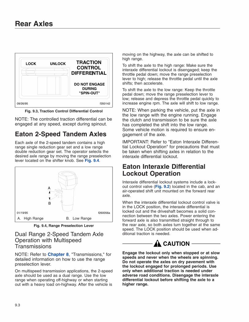
NOTE: The controlled traction differential can beengaged at any speed, except during spinout.
Eaton 2-Speed Tandem AxlesEach axle of the 2-speed tandem contains a highrange single reduction gear set and a low rangedouble reduction gear set. The operator selects thedesired axle range by moving the range preselectionlever located on the shifter knob. See Fig. 9.4.
Dual Range 2-Speed Tandem AxleOperation with MultispeedTransmissionsNOTE: Refer to Chapter 8, "Transmissions," fordetailed information on how to use the rangepreselection lever.
On multispeed transmission applications, the 2-speedaxle should be used as a dual range. Use the lowrange when operating off-highway or when startingout with a heavy load on-highway. After the vehicle is
moving on the highway, the axle can be shifted tohigh range.
To shift the axle to the high range: Make sure theinteraxle differential lockout is disengaged; keep thethrottle pedal down; move the range preselectionlever to high; release the throttle pedal until the axleshifts; then accelerate.
To shift the axle to the low range: Keep the throttlepedal down; move the range preselection lever tolow; release and depress the throttle pedal quickly toincrease engine rpm. The axle will shift to low range.
NOTE: When parking the vehicle, put the axle inthe low range with the engine running. Engagethe clutch and transmission to be sure the axlehas completed the shift into the low range.Some vehicle motion is required to ensure en-gagement of the axle.
IMPORTANT: Refer to "Eaton Interaxle Differen-tial Lockout Operation" for precautions that mustbe taken when shifting axles in relation to theinteraxle differential lockout.
Eaton Interaxle DifferentialLockout OperationInteraxle differential lockout systems include a lock-out control valve (Fig. 9.2) located in the cab, and anair-operated shift unit mounted on the forward rearaxle.
When the interaxle differential lockout control valve isin the LOCK position, the interaxle differential islocked out and the driveshaft becomes a solid con-nection between the two axles. Power entering theforward axle is also transmitted straight through tothe rear axle, so both axles turn together at the samespeed. The LOCK position should be used when ad-ditional traction is needed.
CAUTIONEngage the lockout only when stopped or at slowspeeds and never when the wheels are spinning.Do not operate the axles on dry pavement withthe lockout engaged for prolonged periods. Useonly when additional traction is needed underadverse road conditions. Disengage the interaxledifferential lockout before shifting the axle to ahigher range.
09/26/95 f350142
Fig. 9.3, Traction Control Differential Control
A
B
01/19/95 f260056a
A. High Range B. Low Range
Fig. 9.4, Range Preselection Lever
Rear Axles
9.3

When the interaxle differential lockout control valve isin the UNLOCK position, the interaxle differential al-lows differential action between the axles therebycompensating for different wheel speeds and varia-tions in tire size. Keep the interaxle differential lock-out in the UNLOCK position for normal driving onroads where traction is good. On 2-speed axles, theinteraxle differential must be in the UNLOCK positionbefore attempting to shift the axles out of low or highrange.
Rear Axles
9.4

10
Fifth Wheels and TrailerCouplings
Holland Fifth Wheels . . . . . . . . . . . . . . . . . . . . . . . . . . . . . . . . . . . . . . . . . . . . . . . . . . . . . . . . . . . . . 10.1ASF Castloc II and Simplex Series Fifth Wheels . . . . . . . . . . . . . . . . . . . . . . . . . . . . . . . . . . . . . . . 10.6Fontaine Fifth Wheels . . . . . . . . . . . . . . . . . . . . . . . . . . . . . . . . . . . . . . . . . . . . . . . . . . . . . . . . . . . 10.11Premier Trailer Couplings . . . . . . . . . . . . . . . . . . . . . . . . . . . . . . . . . . . . . . . . . . . . . . . . . . . . . . . . 10.15Holland Trailer Coupling . . . . . . . . . . . . . . . . . . . . . . . . . . . . . . . . . . . . . . . . . . . . . . . . . . . . . . . . . 10.17
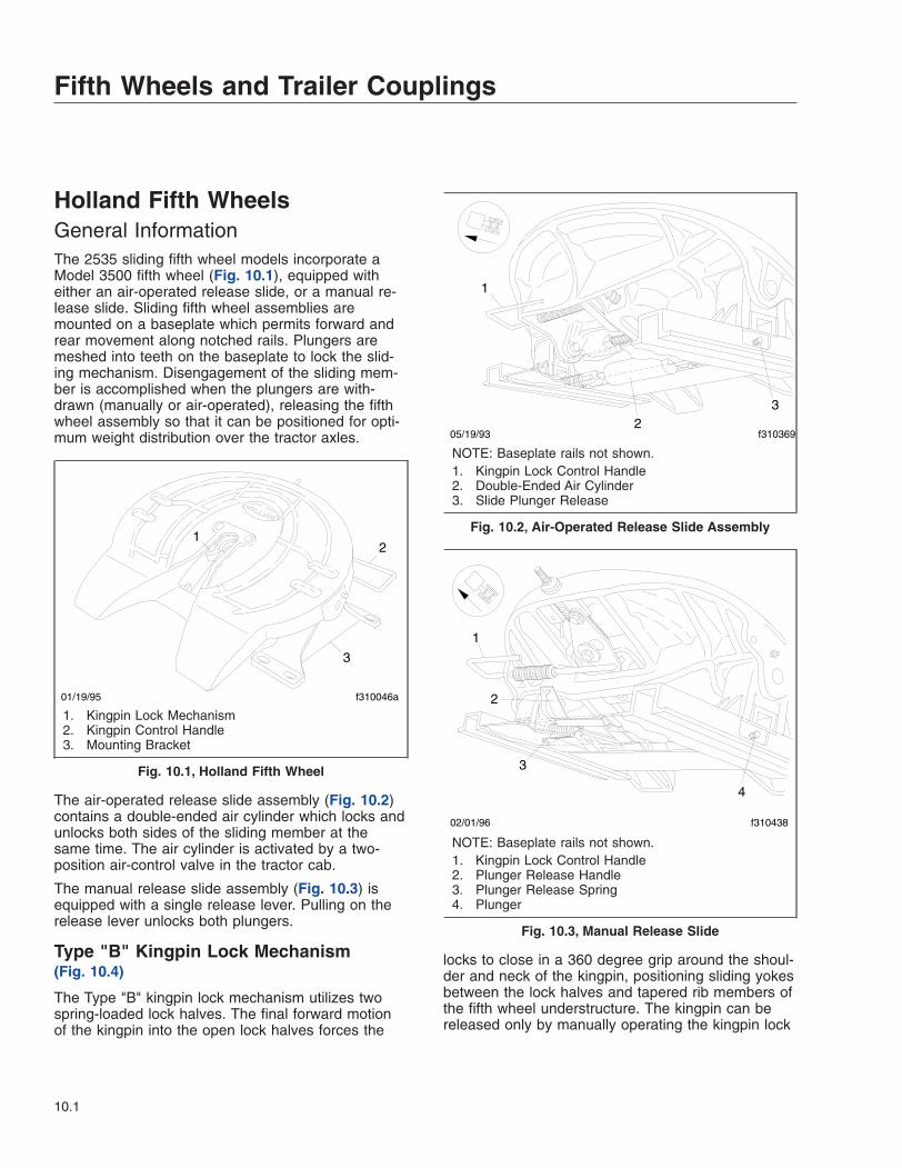
Holland Fifth WheelsGeneral InformationThe 2535 sliding fifth wheel models incorporate aModel 3500 fifth wheel (Fig. 10.1), equipped witheither an air-operated release slide, or a manual re-lease slide. Sliding fifth wheel assemblies aremounted on a baseplate which permits forward andrear movement along notched rails. Plungers aremeshed into teeth on the baseplate to lock the slid-ing mechanism. Disengagement of the sliding mem-ber is accomplished when the plungers are with-drawn (manually or air-operated), releasing the fifthwheel assembly so that it can be positioned for opti-mum weight distribution over the tractor axles.
The air-operated release slide assembly (Fig. 10.2)contains a double-ended air cylinder which locks andunlocks both sides of the sliding member at thesame time. The air cylinder is activated by a two-position air-control valve in the tractor cab.
The manual release slide assembly (Fig. 10.3) isequipped with a single release lever. Pulling on therelease lever unlocks both plungers.
Type "B" Kingpin Lock Mechanism(Fig. 10.4)
The Type "B" kingpin lock mechanism utilizes twospring-loaded lock halves. The final forward motionof the kingpin into the open lock halves forces the
locks to close in a 360 degree grip around the shoul-der and neck of the kingpin, positioning sliding yokesbetween the lock halves and tapered rib members ofthe fifth wheel understructure. The kingpin can bereleased only by manually operating the kingpin lock
12
3
01/19/95 f310046a
1. Kingpin Lock Mechanism2. Kingpin Control Handle3. Mounting Bracket
Fig. 10.1, Holland Fifth Wheel
1
2 3
f310369 05/19/93
NOTE: Baseplate rails not shown.1. Kingpin Lock Control Handle2. Double-Ended Air Cylinder3. Slide Plunger Release
Fig. 10.2, Air-Operated Release Slide Assembly
1
2
3
02/01/96 f310438
4
NOTE: Baseplate rails not shown.1. Kingpin Lock Control Handle2. Plunger Release Handle3. Plunger Release Spring4. Plunger
Fig. 10.3, Manual Release Slide
Fifth Wheels and Trailer Couplings
10.1

control handle. The adjustment nut will compensatefor wear on the lock or kingpin.
Lockguard (Fig. 10.4)
The Holland lockguard is a device that prevents afalse lockup, and is used on all models. The Lock-guard is a spring-tensioned, smooth-surfaced tonguethat the kingpin passes over and depresses whenentering the lock mechanism. The Lockguard willprevent the locks from engaging before the kingpinfully enters the locks. If the kingpin enters the fifthwheel incorrectly and does not depress the tongue,the locks are unable to close.
Fifth Wheel Locking OperationLocking the Fifth Wheel Mechanism
NOTICEBefore attempting to lock or unlock the fifthwheel lock mechanism of a sliding type fifthwheel, the slide release plungers must be in thelocked position. This prevents the sliding mem-ber from moving rapidly to the far forward orrearward position, which could damage the fifthwheel or kingpin.
1. Chock the front and rear of the trailer tires toprevent the trailer from moving.
WARNINGKeep the fifth wheel plate lubricated to preventbinding between the tractor and trailer. A bindingfifth wheel could cause erratic steering and lossof vehicle control, possibly resulting in seriouspersonal injury or death.
2. The kingpin lock mechanism must be fully open,and the fifth wheel plate must be completely lu-bricated with chassis grease. For lubrication in-structions, see Group 31 of the Century ClassTrucks Maintenance Manual.
3. Position the tractor so that the fifth wheel lockopening is in line (both vertically and horizontally)with the trailer kingpin. The kingpin should be ina position to enter the throat of the lockingmechanism, to prevent a false lockup. SeeFig. 10.5. Adjust the trailer landing gear to giveenough alignment height so that the fifth wheelpicks up the trailer on the fifth wheel ramps.
4. With the fifth wheel lock opening aligned with thetrailer kingpin, back the tractor slowly toward thetrailer, making sure that the kingpin correctly en-ters the throat of the locking mechanism. Whenthe trailer is picked up by the fifth wheel, stop thetractor, then continue slow backward motion untilpositive lockup occurs.
5. Apply the tractor parking brakes.
07/11/2000 f310841
2 2
1 1
4
33
5
A B
A. Closed Position, Locked B. Open Position, Unlocked1. Release Handle and Spring2. Adjustment Nut
3. Lock Halves4. Lock Pivot
5. Sliding Yoke
Fig. 10.4, Type "B" Kingpin Lock Mechanism (bottom view)
Fifth Wheels and Trailer Couplings
10.2

WARNINGAdjust the locks correctly to a maximum clear-ance of 1/8 inch (3 mm). Incorrect adjustment ofthe lock could cause the trailer to disconnect,possibly resulting in serious personal injury ordeath.
6. Make a visual check for proper kingpin lockup.Release the tractor parking brakes. Test for king-pin lockup by pulling on the trailer against thechocks. Check for correct maximum clearancebetween the lock halves. If more than 1/8-inch(3.2-mm) clearance exists between the lockhalves, the lock must be adjusted. See Group31 of the Century Class Trucks WorkshopManual for adjustment procedures.
NOTICEAlways make sure the connect-hanger/supportkeeps the trailer air hoses and electrical cablespositioned so that they do not rub on anything.Rubbing may wear through hoses or cables, re-
sulting in air leaks, or exposed or broken wires,potentially affecting trailer brake or electrical sys-tems.
7. After lockup is completed, connect the tractor-to-trailer air system lines and electrical cable to thetrailer. Take care to prevent dirt or foreign mate-rial from entering the air lines.
8. Charge the air brake system with air. Make surethat the air connections do not leak.
9. Retract the trailer landing gear and secure theratchet handle.
10. Remove the chocks from the trailer tires.
11. The load distribution on the front steering axleand rear drive axle(s) will have a direct effect onthe steering control of the vehicle.
Determine the front and rear axle weights byweighing the vehicle on scales designed for thispurpose.
The maximum axle weight ratings are shown onthe Federal Motor Vehicle Safety Standard(FMVSS) label or Canadian Motor Vehicle Safety
1
2
3
4A
11/07/94 f310106a
1
2
3
4
B
D C
A. Locks open.B. Locks closed.C. Kingpin correctly entering the lock. Note how the depressed tongue allows lock halves to close completely around the
neck and shoulder of the kingpin.D. Kingpin incorrectly entering the lock. Note how the steel tongue prevents lock halves from closing, preventing false
lockup.1. Fifth Wheel Plate2. Trailer
3. Kingpin4. Lockguard
Fig. 10.5, Lockguard Mechanism (rear view)
Fifth Wheels and Trailer Couplings
10.3
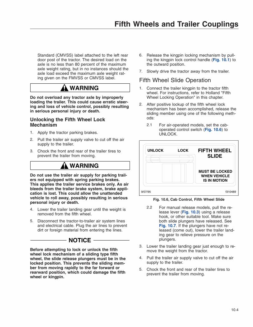
Standard (CMVSS) label attached to the left reardoor post of the tractor. The desired load on theaxle is no less than 80 percent of the maximumaxle weight rating, but in no instances should theaxle load exceed the maximum axle weight rat-ing given on the FMVSS or CMVSS label.
WARNINGDo not overload any tractor axle by improperlyloading the trailer. This could cause erratic steer-ing and loss of vehicle control, possibly resultingin serious personal injury or death.
Unlocking the Fifth Wheel LockMechanism1. Apply the tractor parking brakes.
2. Pull the trailer air supply valve to cut off the airsupply to the trailer.
3. Chock the front and rear of the trailer tires toprevent the trailer from moving.
WARNINGDo not use the trailer air supply for parking trail-ers not equipped with spring parking brakes.This applies the trailer service brakes only. As airbleeds from the trailer brake system, brake appli-cation is lost. This could allow the unattendedvehicle to roll away, possibly resulting in seriouspersonal injury or death.
4. Lower the trailer landing gear until the weight isremoved from the fifth wheel.
5. Disconnect the tractor-to-trailer air system linesand electrical cable. Plug the air lines to preventdirt or foreign material from entering the lines.
NOTICEBefore attempting to lock or unlock the fifthwheel lock mechanism of a sliding type fifthwheel, the slide release plungers must be in thelocked position. This prevents the sliding mem-ber from moving rapidly to the far forward orrearward position, which could damage the fifthwheel or kingpin.
6. Release the kingpin locking mechanism by pull-ing the kingpin lock control handle (Fig. 10.1) tothe outward position.
7. Slowly drive the tractor away from the trailer.
Fifth Wheel Slide Operation1. Connect the trailer kingpin to the tractor fifth
wheel. For instructions, refer to Holland "FifthWheel Locking Operation" in this chapter.
2. After positive lockup of the fifth wheel lockmechanism has been accomplished, release thesliding member using one of the following meth-ods:
2.1 For air-operated models, set the cab-operated control switch (Fig. 10.6) toUNLOCK.
2.2 For manual release models, pull the re-lease lever (Fig. 10.3) using a releasehook, or other suitable tool. Make sureboth slide plungers have released. SeeFig. 10.7. If the plungers have not re-leased (come out), lower the trailer land-ing gear to relieve pressure on theplungers.
3. Lower the trailer landing gear just enough to re-move the weight from the tractor.
4. Pull the trailer air supply valve to cut off the airsupply to the trailer.
5. Chock the front and rear of the trailer tires toprevent the trailer from moving.
9/07/95 f310489
Fig. 10.6, Cab Control, Fifth Wheel Slide
Fifth Wheels and Trailer Couplings
10.4
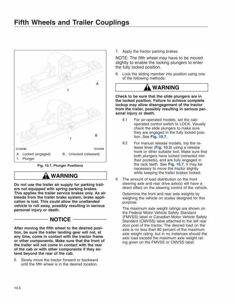
WARNINGDo not use the trailer air supply for parking trail-ers not equipped with spring parking brakes.This applies the trailer service brakes only. As airbleeds from the trailer brake system, brake appli-cation is lost. This could allow the unattendedvehicle to roll away, possibly resulting in seriouspersonal injury or death.
NOTICEAfter moving the fifth wheel to the desired posi-tion, be sure the trailer landing gear will not, atany time, come in contact with the tractor frameor other components. Make sure that the front ofthe trailer will not come in contact with the rearof the cab or with other components if they ex-tend beyond the rear of the cab.
6. Slowly move the tractor forward or backwarduntil the fifth wheel is in the desired location.
7. Apply the tractor parking brakes.
NOTE: The fifth wheel may have to be movedslightly to enable the locking plungers to enterthe fully locked position.
8. Lock the sliding member into position using oneof the following methods:
WARNINGCheck to be sure that the slide plungers are inthe locked position. Failure to achieve completelockup may allow disengagement of the tractorfrom the trailer, possibly resulting in serious per-sonal injury or death.
8.1 For air-operated models, set the cab-operated control switch to LOCK. Visuallycheck the slide plungers to make surethey are engaged in the fully locked posi-tion. See Fig. 10.7.
8.2 For manual release models, trip the re-lease lever (Fig. 10.3) using a releasehook or other suitable tool. Make sure thatboth plungers have locked (retracted intotheir pockets), and are fully engaged inthe rack teeth. See Fig. 10.7. It may benecessary to move the tractor slightlywhile keeping the trailer brakes locked.
9. The amount of load distribution on the frontsteering axle and rear drive axle(s) will have adirect effect on the steering control of the vehicle.
Determine the front and rear axle weights byweighing the vehicle on scales designed for thispurpose.
The maximum axle weight ratings are shown onthe Federal Motor Vehicle Safety Standard(FMVSS) label or Canadian Motor Vehicle SafetyStandard (CMVSS) label attached to the left reardoor post of the tractor. The desired load on theaxle is no less than 80 percent of the maximumaxle weight rating, but in no instances should theaxle load exceed the maximum axle weight rat-ing given on the FMVSS or CMVSS label.
1
1
A
B
01/24/96 f310439
A. Locked (engaged) B. Unlocked (released)1. Plunger
Fig. 10.7, Plunger Positions
Fifth Wheels and Trailer Couplings
10.5

WARNINGDo not overload any tractor axle by improperlyloading the trailer. This could cause erratic steer-ing and loss of vehicle control, possibly resultingin serious personal injury or death.
Fifth Wheel LubricationFor lubrication instructions, see Group 31 of theCentury Class Trucks Maintenance Manual.
ASF Castloc II and SimplexSeries Fifth WheelsGeneral InformationThe ASF Castloc® II and Simplex® series fifthwheels are used for pulling trailers having the stan-dard 2-inch (51-mm) diameter kingpin. When in-stalled as a stationary fifth wheel (Fig. 10.8), theyare bracket-mounted to the tractor frame in a positionthat best distributes the trailer load over the tractoraxles. When used as a sliding fifth wheel (Fig. 10.9),they are mounted on the Taperloc® sliding mount(air-operated or manual release).
The fifth wheel lock mechanism for the trailer kingpinconsists of a rotating jaw that grips the trailer kingpinand a spring-actuated lock. The jaw rotates on a jawpin during coupling and uncoupling operations. King-pin lockup occurs when the kingpin is forced into thejaw and the operating rod handle moves to the
locked position. The kingpin is released either by ac-tivating a manual operating rod, or if equipped withTouchloc®, by a dash mounted release-knob, whichactivates an air cylinder underneath the top plate.The air cylinder activates the operating rod. The op-erating rod is located on the left side of the fifthwheel for Castloc II and Simplex II fifth wheels, andon the right side for the Simplex fifth wheel assem-bly.
On sliding fifth wheels, the top plate is mounted on asliding saddle plate, which slides along the baseplateattached to the tractor frame. The baseplate railsallow forward and rear movement of the slide assem-bly, for optimum weight distribution over the tractoraxles.
Tapered slots in the baseplate rails, aligned in 4-inch(102-mm) increments, provide for location of the fifthwheel along the baseplate. Retractable, spring-actuated lockpins are positioned through the slots tohold the fifth wheel in the desired position. The lock-pins are retracted either manually or by an air-operated cylinder controlled from the cab.
The manually-operated slide contains an operatingrod (Fig. 10.9) which unlocks both sides of the plateat the same time.
The air-operated sliding saddle plate contains an aircylinder which moves the operating lever to unlockboth sides of the plate at the same time. The air cyl-inder is activated by a two-position air-control valvein the tractor cab.
f310353b
12
3
4
10/26/2010
1. Lubricant Grooves2. Safety Latch
3. Operating Rod4. Mounting Bracket
Fig. 10.8, Simplex Stationary Fifth Wheel
1
2
3
45
6
3
10/26/2010 f310445
7
8
1. Baseplate2. Bolted Stop3. Baseplate Rail4. Fifth Wheel Mount
5. Slider Saddle Plate6. Safety Latch7. Operating Rod8. Operating Lever
Fig. 10.9, Taperloc Slide, Manually-Operated Release
Fifth Wheels and Trailer Couplings
10.6

Fifth Wheel Lock Mechanism for TrailerKingpin (Fig. 10.10)
The Castloc II and Simplex Series fifth wheel lockmechanism consists of a rotating jaw and a spring-actuated lock that grips the trailer kingpin. The jawrotates on an eccentric pin during coupling and un-coupling operations. The spring-actuated lock holdsthe jaw in the locked position once kingpin lockuphas occurred.
In the locked position, there is approximately 1/16-inch (1.6-mm) clearance between the jaw and king-pin. The jaw eccentric pin can be removed and ro-tated to compensate for wear and maintain anapproximate 1/16-inch (1.6-mm) clearance duringservice.
Placing the operating rod in the lockset positionmoves the lock away from the jaw. This action un-locks the jaw so that it can be rotated by movementof the kingpin. When the tractor is moved out fromunder the trailer, the kingpin will rotate the jaw untilthe jaw is in the unlocked position, allowing the king-
pin to move out of the mechanism. With the jaw inthe fully open position, the operating rod drops out ofthe lockset position, and the fifth wheel is ready forcoupling. See Fig. 10.11.
During coupling, the kingpin contacts and rotates thejaw into the locked position. This action automaticallymoves the operating rod into the locked position.This securely locks the jaw around the kingpin. In thelocked position the safety latch swings freely over theoperating rod. See Fig. 10.12.
Fifth Wheel Locking and UnlockingLocking the Fifth Wheel Lock Mechanism1. Chock the front and rear of the trailer tires to
prevent the trailer from moving.
NOTICEBefore attempting to lock or unlock the fifthwheel lock mechanism of a sliding type fifthwheel, the slide release pull handle, if soequipped, and the slide locking wedges must be
10/26/2010 f310446
1
23 4
A
B C
56
A. Locked PositionB. Jaw movement compresses spring.C. Fully open.1. Operating Lever2. Safety Latch3. Jaw
4. Jaw Eccentric Pin5. Lock6. Spring
Fig. 10.10, ASF Castloc II and Simplex Series KingpinLocking Mechanism Operation
1
1
2
3
11/02/2010 f310447
1. Safety Latch2. Operating Rod (locked)3. Operating Rod (unlocked)
Fig. 10.11, Simplex Kingpin Locking Mechanism,Locking and Unlocking
Fifth Wheels and Trailer Couplings
10.7

in the locked position. This prevents the slidingmember from moving rapidly to the far forward orrearward position, which could damage the fifthwheel member or kingpin.
2. The fifth wheel jaw must be fully open. Makesure that the operating rod is in the unlocked po-sition. The fifth wheel must be completely lubri-cated with chassis or multi-purpose grease. Forlubrication instructions, see Group 31 of theCentury Class Trucks Maintenance Manual.
WARNINGKeep the fifth wheel plate lubricated to preventbinding between the tractor and trailer. A bindingfifth wheel could cause erratic steering and lossof vehicle control, possibly resulting in seriouspersonal injury or death.
3. Make sure the fifth wheel top plate is tilted so theramps are as low as possible. If equipped withan air suspension, make sure the air bags arecompletely inflated.
4. Position the tractor so that the center of the fifthwheel is in line with the trailer kingpin. The king-pin should be in a position to enter the throat ofthe locking mechanism. See Fig. 10.10. Adjustthe trailer landing gear so that the lower fronttrailer edge contacts the top surface of the tiltedfifth wheel plate, approximately 8 inches (20 cm)before the fifth wheel center.
5. With the fifth wheel lock opening aligned with thetrailer kingpin, back the tractor slowly toward thetrailer, making sure that the kingpin enters the
throat of the locking mechanism. Continue back-ward motion until positive lockup occurs.
6. Apply the tractor parking brakes.
7. Make a visual check (even if equipped with theTouchloc air-operated system) for positive king-pin lockup. The trailer bed plate must be flush onthe fifth wheel plate surface. When positivelockup has occurred, the fifth wheel operatingrod will have moved inward to the locked posi-tion, and the safety latch will swing freely overthe operating rod. See Fig. 10.12.
NOTE: Only when the operating rod is fully re-tracted in the locked position will the safety latchbe freely rotated down.
8. Release the tractor parking brakes. Test for king-pin lockup by pulling on the trailer against thechocks.
NOTICEAlways make sure the connect-hanger/supportkeeps the trailer air hoses and electrical cablespositioned so that they do not rub on anything.Rubbing may wear through hoses or cables, re-sulting in air leaks, or exposed or broken wires,potentially affecting trailer brake or electrical sys-tems.
9. After lockup is completed, connect the tractor-to-trailer air system lines and electrical cable to thetrailer. Take care to prevent dirt or foreign mate-rial from entering the air system lines.
10. Charge the air brake system with air. Make surethat the air connections do not leak.
WARNINGAdjust the jaw pin if there is more than 1/8-inch(3-mm) clearance between the kingpin and thelock. Incorrect adjustment could cause the trailerto disconnect, possibly resulting in serious per-sonal injury or death.
11. With the trailer wheels chocked and the brakesset, check for clearance between the kingpin andthe fifth wheel jaws by moving the tractor forwardand backward against the locked kingpin. Aclearance of approximately 1/16 inch (1.6 mm)between the jaw and kingpin is allowable. Whenclearance between the jaw and kingpin exceeds
1
2
10/26/2010 f310448
1. Safety Latch 2. Operating Rod
Fig. 10.12, Simplex Kingpin Locking Mechanism, SafetyLatch (locked position)
Fifth Wheels and Trailer Couplings
10.8

1/8 inch (3 mm), adjust the jaw to restore the1/16-inch (1.6-mm) clearance between the jawand kingpin. For instructions, see Group 31 ofthe Century Class Trucks Workshop Manual.
12. Retract the trailer landing gear, and secure theratchet handle.
13. Remove the chocks from the trailer tires.
14. The load distribution on the front steering axleand rear drive axle(s) will have a direct effect onthe steering control of the vehicle.
Determine the front and rear axle weights byweighing the vehicle on scales designed for thispurpose.
The maximum axle weight ratings are shown onthe Federal Motor Vehicle Safety Standard(FMVSS) label or Canadian Motor Vehicle SafetyStandard (CMVSS) label attached to the left reardoor post of the tractor. The desired load on theaxle is no less than 80 percent of the maximumaxle weight rating, but in no instances should theaxle load exceed the maximum axle weight rat-ings given on the FMVSS or CMVSS label.
WARNINGDo not overload any tractor axle by improperlyloading the trailer. This could cause erratic steer-ing and loss of vehicle control, possibly resultingin serious personal injury or death.
Unlocking the Fifth Wheel LockMechanism1. Apply the tractor parking brakes.
2. Pull the trailer air supply valve to cut off the airsupply to the trailer.
WARNINGDo not use the trailer air supply for parking trail-ers not equipped with spring parking brakes.This applies the trailer service brakes only. As airbleeds from the trailer brake system, brake appli-cation is lost. This could allow the unattendedvehicle to roll away, possibly resulting in seriouspersonal injury or death.
3. Chock the front and rear of the trailer tires toprevent the trailer from moving.
4. Lower the trailer landing gear until the trailerrises about 1/2 inch (13 mm).
5. Disconnect the tractor-to-trailer air system linesand electrical cable. Plug the air lines to preventdirt or foreign material from entering the lines.
NOTICEBefore attempting to unlock the fifth wheel lockmechanism of a sliding type fifth wheel, the slideoperating rod (Fig. 10.9) must be in the lockedposition, and the slide lockpins must be in thelocked position (fully inserted in baseplate railslots). This prevents the sliding member frommoving rapidly to the far forward or rearward po-sition, which could damage the fifth wheel mem-ber or kingpin.
6. If equipped with a manual kingpin lock release:Release the kingpin lock mechanism by raisingthe safety latch to the rear and pulling the lockoperating rod out and up into the lockset posi-tion. See Fig. 10.11. The offset of the lock con-trol upper rod should bottom against the platecasting above the hole. If the operating rod can-not be pulled to the lockset position, back thetractor slightly to release the kingpin forceagainst the jaw.
If equipped with an air-operated kingpin lock re-lease: Pull the air-release knob on the dash.From outside the cab, visually check that the op-erating rod has bottomed out against the platecasting above the hole. See Fig. 10.11. If theoperating rod isn’t in the unlocked position, backthe tractor slightly to release the kingpin forceagainst the jaw.
IMPORTANT: If equipped with an air-operatedlock release, you still must make a visual checkof the operating rod to make sure it is in the un-locked position
7. Slowly drive the tractor away from the trailer.
Fifth Wheel Slide Operation1. Chock the front and rear of the trailer tires to
prevent the trailer from moving.
2. Connect the trailer kingpin to the tractor fifthwheel. For instructions, refer to "Fifth WheelLocking Operation," in this chapter.
Fifth Wheels and Trailer Couplings
10.9
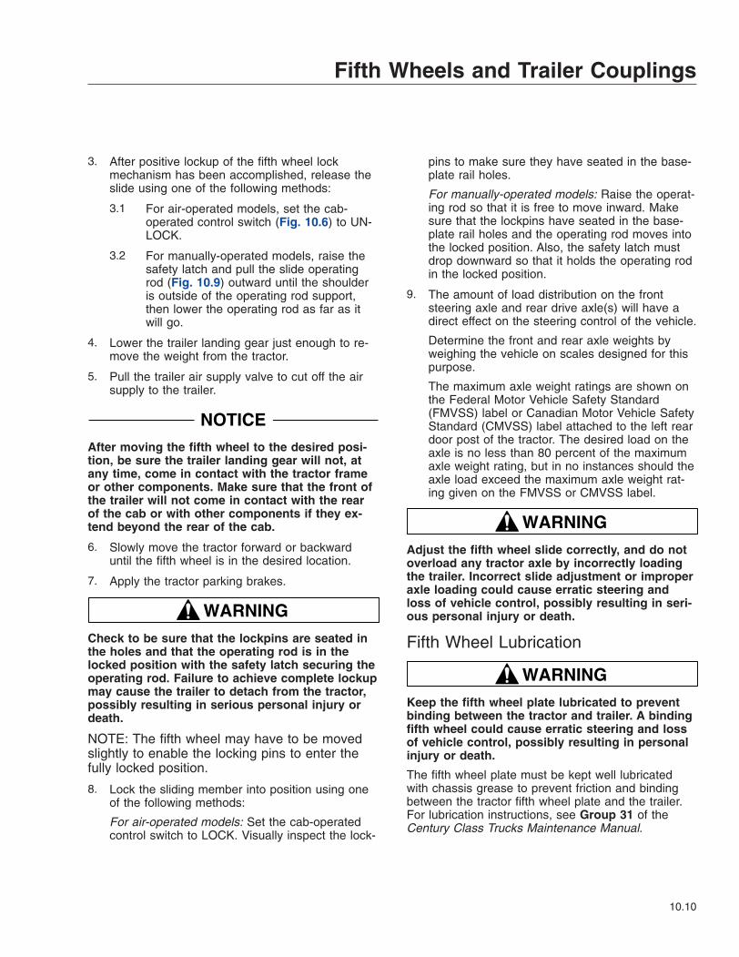
3. After positive lockup of the fifth wheel lockmechanism has been accomplished, release theslide using one of the following methods:
3.1 For air-operated models, set the cab-operated control switch (Fig. 10.6) to UN-LOCK.
3.2 For manually-operated models, raise thesafety latch and pull the slide operatingrod (Fig. 10.9) outward until the shoulderis outside of the operating rod support,then lower the operating rod as far as itwill go.
4. Lower the trailer landing gear just enough to re-move the weight from the tractor.
5. Pull the trailer air supply valve to cut off the airsupply to the trailer.
NOTICEAfter moving the fifth wheel to the desired posi-tion, be sure the trailer landing gear will not, atany time, come in contact with the tractor frameor other components. Make sure that the front ofthe trailer will not come in contact with the rearof the cab or with other components if they ex-tend beyond the rear of the cab.
6. Slowly move the tractor forward or backwarduntil the fifth wheel is in the desired location.
7. Apply the tractor parking brakes.
WARNINGCheck to be sure that the lockpins are seated inthe holes and that the operating rod is in thelocked position with the safety latch securing theoperating rod. Failure to achieve complete lockupmay cause the trailer to detach from the tractor,possibly resulting in serious personal injury ordeath.
NOTE: The fifth wheel may have to be movedslightly to enable the locking pins to enter thefully locked position.
8. Lock the sliding member into position using oneof the following methods:
For air-operated models: Set the cab-operatedcontrol switch to LOCK. Visually inspect the lock-
pins to make sure they have seated in the base-plate rail holes.
For manually-operated models: Raise the operat-ing rod so that it is free to move inward. Makesure that the lockpins have seated in the base-plate rail holes and the operating rod moves intothe locked position. Also, the safety latch mustdrop downward so that it holds the operating rodin the locked position.
9. The amount of load distribution on the frontsteering axle and rear drive axle(s) will have adirect effect on the steering control of the vehicle.
Determine the front and rear axle weights byweighing the vehicle on scales designed for thispurpose.
The maximum axle weight ratings are shown onthe Federal Motor Vehicle Safety Standard(FMVSS) label or Canadian Motor Vehicle SafetyStandard (CMVSS) label attached to the left reardoor post of the tractor. The desired load on theaxle is no less than 80 percent of the maximumaxle weight rating, but in no instances should theaxle load exceed the maximum axle weight rat-ing given on the FMVSS or CMVSS label.
WARNINGAdjust the fifth wheel slide correctly, and do notoverload any tractor axle by incorrectly loadingthe trailer. Incorrect slide adjustment or improperaxle loading could cause erratic steering andloss of vehicle control, possibly resulting in seri-ous personal injury or death.
Fifth Wheel Lubrication
WARNINGKeep the fifth wheel plate lubricated to preventbinding between the tractor and trailer. A bindingfifth wheel could cause erratic steering and lossof vehicle control, possibly resulting in personalinjury or death.
The fifth wheel plate must be kept well lubricatedwith chassis grease to prevent friction and bindingbetween the tractor fifth wheel plate and the trailer.For lubrication instructions, see Group 31 of theCentury Class Trucks Maintenance Manual.
Fifth Wheels and Trailer Couplings
10.10

Fontaine Fifth WheelsGeneral InformationThe Fontaine sliding fifth wheel mount is designed toprovide optimum axle loading for maximum tractoruse with different lengths and types of trailers. Thesliding fifth wheel mount is used with the FontaineH5092 series, and 6000/7000 No-Slack II series fifthwheels, and is equipped with either an air-operatedrelease slide (AWB or HAWB models), or a manualrelease slide (MWS or HMWS models).
On Fontaine fifth wheels kingpin release is accom-plished by activating a manual lock control handlelocated on either the right side or left side of the fifthwheel. Kingpin lockup occurs when the kingpin isforced into the jaws and the lock control handlemoves to the locked position.
The fifth wheel top plate is mounted on a slide as-sembly, which is attached to slide rails that aremounted on the vehicle frame. The slide rails permitforward and rearward movement of the slide assem-bly, allowing for optimum weight distribution over thetractor axles.
Slots are evenly spaced along the slide rails, andretractable tapered wedges are positioned throughthe slots to hold the fifth wheel in the desired posi-tion. See Fig. 10.13 or Fig. 10.14.
The slide portion of the sliding model may be at-tached to either an air-operated release slide, or amanual release slide.
The air-operated release slide contains an air cylin-der that locks and unlocks the fifth wheel slide. SeeFig. 10.13. The air cylinder is activated by a two-position air-control valve in the tractor cab.
The manual release slide contains a slide releasepull handle, located on the left side of the fifth wheel,which locks or unlocks the fifth wheel slide. SeeFig. 10.14.
Fifth Wheel Lock Mechanism for TrailerKingpin (Fig. 10.15)
The Fontaine fifth wheel lock mechanism for thetrailer kingpin consists of a spring-loaded jaw and asliding wedge.
The jaw and wedge each have a pin permanentlyattached. The pin on the jaw and the pin on thewedge fit into elongated notches in the lock controlhandle. The notches in the handle control the limit ofmovement for both the jaw and wedge. The notchesare arranged so that the wedge is actuated first dur-ing release of the kingpin.
During lockup, the jaw is moved first with the spring-loaded wedge being allowed to slip in place against
07/25/95 f310189
1
2
1. Locking Wedge 2. Air Cylinder
Fig. 10.13, Air-Operated Sliding Fifth Wheel Mount,AWB Model
07/25/95 f310190
1
2
1. Locking Wedge2. Slide Release Pull Handle
Fig. 10.14, Manual Release Sliding Fifth Wheel Mount,MWS Model
Fifth Wheels and Trailer Couplings
10.11

the jaw. A timing bracket ensures that the wedge andjaw are moved at the proper time.
Placing the lock control handle in the unlocked posi-tion moves the wedge away from the jaw. This actionunlocks the jaw so that it can be moved by the trailerkingpin. When the tractor is moved out from underthe trailer, the kingpin moves the jaw until the kingpinis out of the mechanism. With the jaw in the un-locked position, the lock control handle will remain inthe unlocked position until manually moved by theoperator.
During coupling (Fig. 10.15), the motion of the king-pin entering the jaw will actuate the jaw and wedge.The jaw will move behind the kingpin, followed by thewedge. The purpose of the wedge is to reinforce thejaw and take up slack around the pin. Any wear onthe jaw is immediately taken up by the wedge sothere is no slack in the connection.
Fifth Wheel Locking OperationLocking the Fifth Wheel Lock Mechanism
NOTICEBefore attempting to lock or unlock the fifthwheel lock mechanism of a sliding type fifthwheel, the slide release pull handle, if soequipped, and the slide locking wedges must bein the locked position. This prevents the slidingmember from moving rapidly to the far forward orrearward position, which could damage the fifthwheel member or kingpin.
1. Chock the front and rear of the trailer tires toprevent the trailer from moving.
WARNINGKeep the fifth wheel plate lubricated to preventbinding between the tractor and trailer. A bindingfifth wheel could cause erratic steering and lossof vehicle control, possibly resulting in seriouspersonal injury or death.
2. The kingpin lock mechanism must be fully open,the fifth wheel plate must be completely lubri-cated with chassis grease. For lubrication in-structions, see Group 31 of the Century ClassTrucks Maintenance Manual.
3. Position the tractor so that the fifth wheel lockopening is in line (both vertically and horizontally)with the trailer kingpin. The kingpin should be ina position to enter the throat of the lockingmechanism (Fig. 10.15). Adjust the trailer landinggear to give enough alignment height for positivekingpin lockup.
4. With the fifth wheel lock opening aligned with thetrailer kingpin, back the tractor slowly toward thetrailer, making sure that the kingpin enters thethroat of the locking mechanism. Continue back-ward motion until positive lockup occurs.
5. Apply the tractor parking brakes.
6. Make a visual and physical check for positivekingpin lockup. When lockup has occurred, thefifth wheel control handle will have moved to thelocked position. Make sure that the safety latchis down over the lock control handle. See
1
2 A
3
B C
10/26/2010 f310184c
A. Unlocked PositionB. Locking
C. Locked
1. Wedge2. Jaw
3. Trailer Kingpin
Fig. 10.15, Fontaine Kingpin Lock Mechanism
Fifth Wheels and Trailer Couplings
10.12

Fig. 10.16. This will hold the control handle inthe locked position.
7. Release the tractor parking brakes. Test for king-pin lockup by pulling on the trailer against thechocks.
NOTICEAlways make sure the connect-hanger/supportkeeps the trailer air hoses and electrical cablespositioned so that they do not rub on anything.Rubbing may wear through hoses or cables, re-sulting in air leaks, or exposed or broken wires,potentially affecting trailer brake or electrical sys-tems.
8. After lockup is completed, connect the tractor-to-trailer air system lines and the electrical cable tothe trailer. Take care to prevent dirt or foreignmaterial from entering the air system lines.
9. Charge the air brake system with air. Make surethat the air connections do not leak.
WARNINGIncorrect fifth wheel lock adjustment could causethe trailer to disconnect, possibly resulting in se-rious personal injury or death.
10. With the trailer wheels chocked and the brakesset, check for clearance between the kingpin andthe fifth wheel jaws by moving the tractor forwardand backward against the locked kingpin. Thereshould be no slack between the tractor and thetrailer. If slack is present, uncouple the trailer.
For adjustment instructions, refer to the appli-cable manufacturer’s service information.
11. Retract the trailer landing gear, and secure theratchet handle. Remove the chocks from thetrailer tires.
12. The load distribution on the front steering axleand rear drive axle(s) will have a direct effect onthe steering control of the vehicle.
Determine the front and rear axle weights byweighing the vehicle on scales designed for thispurpose.
The maximum axle weight ratings are given onthe Federal Motor Vehicle Safety Standard(FMVSS) label or Canadian Motor Vehicle SafetyStandard (CMVSS) label attached to the left reardoor post of the tractor. The desired load on theaxle is no less than 80 percent of the maximumaxle weight rating, but in no instances should theaxle load exceed the maximum axle weight rat-ing given on the FMVSS or CMVSS label.
WARNINGDo not overload any tractor axle by improperlyloading the trailer. This could cause erratic steer-ing and loss of vehicle control, possibly resultingin serious personal injury or death.
Unlocking the Fifth Wheel LockMechanism1. Apply the tractor parking brakes.
2. Pull the trailer air supply valve to cut off the airsupply to the trailer.
1
1
2
2 10/26/2010 f310110a
A
B
NOTE: Make sure the safety latch is down when thecontrol handle is locked.
A. Unlocked B. Locked1. Safety Latch 2. Lock Control Handle
Fig. 10.16, Fontaine Fifth Wheel, Locking andUnlocking
Fifth Wheels and Trailer Couplings
10.13
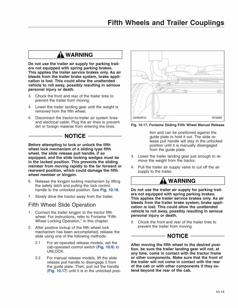
WARNINGDo not use the trailer air supply for parking trail-ers not equipped with spring parking brakes.This applies the trailer service brakes only. As airbleeds from the trailer brake system, brake appli-cation is lost. This could allow the unattendedvehicle to roll away, possibly resulting in seriouspersonal injury or death.
3. Chock the front and rear of the trailer tires toprevent the trailer from moving.
4. Lower the trailer landing gear until the weight isremoved from the fifth wheel.
5. Disconnect the tractor-to-trailer air system linesand electrical cable. Plug the air lines to preventdirt or foreign material from entering the lines.
NOTICEBefore attempting to lock or unlock the fifthwheel lock mechanism of a sliding type fifthwheel, the slide release pull handle, if soequipped, and the slide locking wedges must bein the locked position. This prevents the slidingmember from moving rapidly to the far forward orrearward position, which could damage the fifthwheel member or kingpin.
6. Release the kingpin locking mechanism by liftingthe safety latch and pulling the lock controlhandle to the unlocked position. See Fig. 10.16.
7. Slowly drive the tractor away from the trailer.
Fifth Wheel Slide Operation1. Connect the trailer kingpin to the tractor fifth
wheel. For instructions, refer to Fontaine "FifthWheel Locking Operation," in this chapter.
2. After positive lockup of the fifth wheel lockmechanism has been accomplished, release theslide using one of the following methods:
2.1 For air-operated release models, set thecab-operated control switch (Fig. 10.6) toUNLOCK.
2.2 For manual release models, lift the sliderelease pull handle to disengage it fromthe guide plate. Then, pull out the handle(Fig. 10.17) until it is in the unlocked posi-
tion and can be positioned against theguide plate to hold it out. The slide re-lease pull handle will stay in the unlockedposition until it is manually disengagedfrom the guide plate.
3. Lower the trailer landing gear just enough to re-move the weight from the tractor.
4. Pull the trailer air supply valve to cut off the airsupply to the trailer.
WARNINGDo not use the trailer air supply for parking trail-ers not equipped with spring parking brakes.This applies the trailer service brakes only. As airbleeds from the trailer brake system, brake appli-cation is lost. This could allow the unattendedvehicle to roll away, possibly resulting in seriouspersonal injury or death.
5. Chock the front and rear of the trailer tires toprevent the trailer from moving.
NOTICEAfter moving the fifth wheel to the desired posi-tion, be sure the trailer landing gear will not, atany time, come in contact with the tractor frameor other components. Make sure that the front ofthe trailer will not come in contact with the rearof the cab or with other components if they ex-tend beyond the rear of the cab.
10/26/2010 f310050
Fig. 10.17, Fontaine Sliding Fifth Wheel Manual Release
Fifth Wheels and Trailer Couplings
10.14
6. Slowly move the tractor forward or backwarduntil the fifth wheel is in the desired location.
7. Apply the tractor parking brakes.
NOTE: The fifth wheel may have to be movedslightly to enable the locking wedges to enterthe fully locked position.
8. Lock the sliding member in position using one ofthe following methods:
WARNINGCheck to be sure that the lockpins are seated inthe holes. Failure to achieve complete lockupmay cause the trailer to detach from the tractor,possibly resulting in serious personal injury ordeath.
8.1 For air-operated release models, set thecab-operated slide control switch toLOCK. Visually inspect the lockingwedges to make sure that they are fullyinserted in the slide rail slots.
8.2 For manual release models, disengagethe slide release pull handle from theguide plate. The slide release pull handleis spring-loaded in the locked position andwill seek the locked position when disen-gaged from the guide plate. The fifthwheel may have to be moved slightly toenable the locking wedges to fully enterthe locked position. When the slide re-lease pull handle returns to the fullylocked position, visually and physicallycheck the locking wedges to make surethey are fully inserted into the slots in theslide rails. Make sure the slide release pullhandle is locked in position against theguide plate.
9. The amount of load distribution on the frontsteering axle and rear drive axle(s) will have adirect effect on the steering control of the vehicle.
Determine the front and rear axle weights byweighing the vehicle on scales designed for thispurpose.
The maximum axle weight ratings are given onthe Federal Motor Vehicle Safety Standard(FMVSS) label or Canadian Motor Vehicle SafetyStandard (CMVSS) label attached to the left reardoor post of the tractor. The desired load on the
axle is no less than 80 percent of the maximumaxle weight rating, but in no instances should theaxle load exceed the maximum axle weight rat-ing given on the FMVSS or CMVSS label.
WARNINGAdjust the fifth wheel slide correctly, and do notoverload any tractor axle by incorrectly loadingthe trailer. Incorrect slide adjustment or improperaxle loading could cause erratic steering andloss of vehicle control, possibly resulting in seri-ous personal injury or death.
Fifth Wheel Lubrication
WARNINGKeep the fifth wheel plate lubricated to preventbinding between the tractor and trailer. A bindingfifth wheel could cause erratic steering and lossof vehicle control, possibly resulting in seriouspersonal injury or death.
For lubrication instructions, see Group 31 of theCentury Class Trucks Maintenance Manual.
Premier Trailer CouplingsIMPORTANT: Before operating the Premier cou-pling, refer to the Premier web site atwww.premier-mfg.com for complete safety,operation, and maintenance instructions.
General InformationTrailer couplings, used only on trucks, are attachedto the rear closing crossmember.
The Premier 260 and 460 trailer couplings(Fig. 10.18) have a rigid pintle hook, and are air-adjusted. An air chamber, mounted forward of thecoupling, operates a pushrod, which pushes againsta shoe inside the coupling. The shoe maintains con-stant pressure on the eye of the trailer drawbar whenit’s over the pintle hook. This takes up any slack inthe trailer connection, providing smoother towing andless wear on the pintle hook. The air pressure is acti-vated when the trailer brakes are released.
The Premier 690 trailer coupling (Fig. 10.19) has amoveable pintle hook, and is non-air adjusted. It isused for heavy-duty applications.
Fifth Wheels and Trailer Couplings
10.15

Operation
WARNINGIf at any time the 690 coupling is bound up (jack-knifed), the 294 bolt MUST be replaced immedi-ately! Do not use the coupling until the bolt hasbeen replaced. In addition, carefully inspect the690 coupling, drawbar, drawbar eye, front endassembly, and tail board for damage. Failure todo so may result in trailer separation from the
truck while in use, resulting in serious personalinjury or property damage.
Trailer Hookup1. Chock the front and rear tires of the trailer.
2. Open the coupling.
Models 260 and 460 (Fig. 10.18): Pull up on thepawl lock; then, while squeezing the pawlwedges together, lift up the pawl assembly. Liftup the latch, and push it up against the pawl as-sembly, locking the latch in place.
Model 690 (Fig. 10.19): Remove the linch pinfrom the handle, then push in on the handle andturn it toward you. Open the pintle hook by pull-ing it down and toward you. Release the handle,locking the pintle hook open.
3. Models 260 and 460: Back up the vehicle untilthe drawbar eye is over the pintle hook, thenlower the trailer.
Model 690: Back up the vehicle until the drawbareye enters the open jaw, contacts the back of thepintle hook, and closes the coupling.
4. Close the coupling.
Models 260 and 460: Push in on the pawlwedges and lift the pawl assembly. The latch will
1
2
3
4
5
6
1
2
3
45
6
AB
01/20/95 f310312a
A. Model 260 B. Model 4601. Pintle Hook2. Latch
3. Pawl Assembly4. Pawl Lock
5. Pawl Wedge6. Shoe
Fig. 10.18, Premier 260 and 460 Trailer Couplings
1 2
3
f310313a07/13/2010
4
1. Linch Pin2. Handle
3. Pintle Hook4. 294 Bolt
Fig. 10.19, Premier 690 Trailer Coupling
Fifth Wheels and Trailer Couplings
10.16

drop into the closed position. Lock the latch bylowering the pawl assembly.
Model 690: The pintle hook will automaticallyclose and lock from the pressure of the drawbareye against it. Install the linch pin.
NOTICEAlways make sure the connect-hanger/supportkeeps the trailer air hoses and electrical cablespositioned so that they do not rub on anything.Rubbing may wear through hoses or cables, re-sulting in air leaks, or exposed or broken wires,potentially affecting trailer brake or electrical sys-tems.
5. Hook up the trailer’s electrical and air lines.
6. Remove the chocks from the trailer’s tires.
Trailer Release1. Apply the truck and trailer parking brakes.
WARNINGDo not use the trailer air supply for parking trail-ers not equipped with spring parking brakes.This applies the trailer service brakes only. As airbleeds from the trailer brake system, brake appli-cation is lost. This could allow the unattendedvehicle to roll away, possibly resulting in seriouspersonal injury or death.
2. Chock the front and rear tires of the trailer.
3. Disconnect the trailer air and electrical lines.Plug the air lines to keep out dirt.
4. Take the weight of the trailer drawbar eye off thepintle hook.
5. Open the coupling.
Models 260 and 460: Pull up on the pawl lock;then, while squeezing the pawl wedges together,lift up the pawl assembly. Lift up the latch, andpush it up against the pawl, locking the latch inplace.
Model 690: Remove the linch pin from thehandle, then push in on the handle and turn ittoward you. Open the pintle hook by pulling itdown and toward you. Release the handle, lock-ing the pintle hook open.
6. Slowly drive the vehicle away from the trailer.
Holland Trailer CouplingGeneral InformationThe Holland PH–T–60–AL trailer coupling is de-signed for use with trailers having a maximum grossweight of 10,000 lbs. It is a rigid type pintle hook,used only on truck applications, and is fastened tothe rear closing crossmember of the vehicle. SeeFig. 10.20. It is a non-air adjusted coupling.
OperationTrailer Hookup1. Chock the front and rear tires of the trailer.
2. Remove the cotter pin, then lift the lock and raisethe latch.
3. Back up the vehicle until the drawbar eye is overthe pintle hook.
4. Lower the trailer until the drawbar eye rests onthe pintle hook.
5. Close the latch, then insert the cotter pin.
NOTICEAlways make sure the connect-hanger/supportkeeps the trailer air hoses and electrical cablespositioned so that they do not rub on anything.Rubbing may wear through hoses or cables, re-sulting in air leaks, or exposed or broken wires,
1 2
3
4
01/20/95 f310314a
1. Lock2. Cotter Pin
3. Latch4. Pintle Hook
Fig. 10.20, Holland PH-T-60-AL Trailer Coupling
Fifth Wheels and Trailer Couplings
10.17
potentially affecting trailer brake or electrical sys-tems.
6. Hook up the trailer’s electrical and air lines.
7. Remove the chocks from the trailer’s tires.
Trailer Release1. Apply the truck and trailer parking brakes.
WARNINGDo not use the trailer air supply for parking trail-ers not equipped with spring parking brakes.This applies the trailer service brakes only. As airbleeds from the trailer brake system, brake appli-cation is lost. This could allow the unattendedvehicle to roll away, possibly resulting in seriouspersonal injury or death.
2. Chock the front and rear tires of the trailer.
3. Disconnect the trailer air and electrical lines.Plug the air lines to keep out dirt.
4. Take the weight of the trailer drawbar off thepintle hook.
5. Open the latch by first removing the cotter pin;then lift up the lock and raise the latch.
6. Slowly drive the vehicle away from the trailer.
Fifth Wheels and Trailer Couplings
10.18
11
Pretrip and Post-TripInspections and
MaintenancePretrip and Post-Trip Inspection Checklists . . . . . . . . . . . . . . . . . . . . . . . . . . . . . . . . . . . . . . . . . . . . 11.1Daily Pretrip Inspection and Maintenance . . . . . . . . . . . . . . . . . . . . . . . . . . . . . . . . . . . . . . . . . . . . . 11.3Weekly Post-Trip Inspection and Maintenance . . . . . . . . . . . . . . . . . . . . . . . . . . . . . . . . . . . . . . . . . 11.9Monthly Post-Trip Inspection and Maintenance . . . . . . . . . . . . . . . . . . . . . . . . . . . . . . . . . . . . . . . 11.11

Pretrip and Post-TripInspection ChecklistsPeriodic Inspections andMaintenance, General InformationRegulations in Canada and the U.S. clearly indicatethat it is the driver’s responsibility to perform an in-spection, and ensure the complete road-worthinessof a vehicle, before placing it into service. Commer-cial vehicles may be subject to inspection by autho-rized inspectors, and an unsafe vehicle can be takenout of service until the driver or owner repairs it.
Use the following checklists to ensure that vehiclecomponents are in good working condition beforeeach trip. Careful inspections eliminate stops later tofix overlooked or forgotten items.
The checklists in this chapter can be copied and keptas a record that the procedures have been com-pleted. For details on how to inspect each item onthe checklists, see the corresponding procedure laterin this chapter.
ChecklistsDaily Pretrip Inspection ChecklistsSee the following tables for a list of procedures thatshould be performed daily, before the first trip. Placea check mark in the complete (Comp.) column toindicate a procedure has been performed.
Inspector Date
Suspension and Slack Adjusters Comp.1 Suspension components2 Slack adjusters
Wheels and Tires Comp.1 Tire condition2 Tire inflation3 Rim and wheel components4 Wheel bearing oil seals and lubrication levels6 Mud Flaps
Saddle Tank Areas Comp.
1 Drain air reservoirs (without automatic drainvalves)
2 Fuel tank(s) secure
Saddle Tank Areas Comp.3 Frame rails and crossmembers4 Visible exhaust components
Engine Compartment Comp.1 Leakage under engine2 Air intake system3 Engine oil level4 Power steering reservoir level5 Engine coolant level6 Visible engine wiring7 Frame rails
Cab Comp.
1 Reset dash-mounted air intake restrictionindicator
2 Air-pressure warning systems3 Air governor cut-in and cut-out pressures4 Air pressure build-up time5 Air system leakage6 Air pressure reserve7 Mirrors, windows, windshield8 Horn, windshield wipers, windshield washers9 Heater and defroster10 Interior lights11 Exterior lights12 Seat belts and tether belts13 Fuel level14 Mirror adjustment15 Service brakes16 Backup alarm
Pretrip and Post-Trip Inspections and Maintenance
11.1

Weekly Post-trip Inspection ChecklistSee the following table for procedures that should beperformed weekly, post-trip. Place a check mark inthe complete (Comp.) column to indicate a proce-dure has been performed.
Inspector Date
Engine Compartment Comp.1 Windshield washer reservoir level2 Air intake restriction indicator3 Automatic transmission fluid level4 Water in fuel/water separator5 Steering components6 Serpentine drive belts
Monthly Post-trip Inspection ChecklistsSee the following tables for procedures that shouldbe performed monthly, post-trip. Place a check markin the complete (Comp.) column to indicate a proce-dure has been performed.
Inspector Date
Brake Components Comp.1 Brake system components2 Brake chambers3 Air brake lines4 Flex air lines5 Brake linings and brake drums6 Brake lining thickness
Saddle Tank Areas Comp.
1 Drain air reservoirs (with automatic drainvalves)
2 Batteries (location may vary)
Engine Compartment Comp.1 Hydraulic clutch reservoir2 Radiator and heater hoses3 Steering wheel play
Fluids AddedUse the following table to note any fluids that wereadded during the inspection and maintenance proce-dures.
Fluids Added During InspectionFluid Amount Added
Wheel Bearing LubricantEngine OilPower Steering FluidEngine CoolantWindshield Washer FluidAutomatic TransmissionFluidHydraulic Clutch Fluid (DOT4 brake fluid)
Pretrip and Post-Trip Inspections and Maintenance
11.2

Daily Pretrip Inspection andMaintenanceComplete the following inspection and maintenanceprocedures to ensure that vehicle components are ingood working condition before each trip. A driver whois familiar with the vehicle and drives it regularly canperform the daily inspections, then add the weeklyand monthly post-trip inspections as scheduled.
If the driver does not operate the vehicle on a con-sistent basis, all daily, weekly, and monthly inspec-tion and maintenance procedures should be per-formed before the trip.
IMPORTANT: The pre- and post-trip checklists,inspections, and maintenance procedures de-tailed in this chapter are not all-inclusive.Refer to other component and body manufactur-ers’ instructions for specific inspection andmaintenance instructions, as well as local, state,and federal guidelines.
NOTE: If any system or component does notpass this inspection, it must be corrected beforeoperating the vehicle. Whenever equipment re-quires adjustment, replacement, and/or repair,see the Century Class Trucks Workshop Manualfor procedures and specifications.
Suspension and Slack AdjusterInspectionWalk around the vehicle and visually inspect suspen-sion and slack adjuster components.
1. Inspect the following suspension components forsigns of structural damage, cracks, or wear.
• springs
• spring hangers
• shocks
• suspension arms
• suspension brackets
• axle seats
• bushings
2. Inspect slack adjusters for signs of damage. SeeFig. 11.1, Fig. 11.2, or Fig. 11.3.
• Inspect slack adjuster boots, if equipped,for cuts or tears.
• Inspect anchor straps, if equipped, fordamage.
• Look for worn clevis pins on brake cham-ber pushrods.
• Look for missing or damaged cotter pinson the clevis pins.
• Ensure chamber piston rods are in linewith the slack adjusters.
Wheel and Tire InspectionWalk around the vehicle and visually inspect eachwheel and tire assembly.
1. Inspect tire condition for the following:
• valve stem caps on every tire, screwed onfinger-tight
• bulges, cracks, cuts, and penetrations
• oil contamination (petroleum derivatives willsoften the rubber and destroy the tire)
f42139806/17/2003
1
2
3
4 5
6
78
10
9
1. 7/16-inch AdjustingNut
2. Grease Fitting3. Boot4. Link5. Brake Chamber Piston
Rod
6. Clevis7. 1/2-inch Clevis Pin8. 1/4-inch Clevis Pin9. Grease Relief
Opening10. Slack Adjuster Spline
Fig. 11.1, Gunite Automatic Slack Adjuster
Pretrip and Post-Trip Inspections and Maintenance
11.3
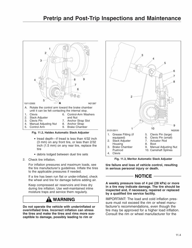
• tread depth—if tread is less than 4/32 inch(3 mm) on any front tire, or less than 2/32inch (1.5 mm) on any rear tire, replace thetire
• debris lodged between duel tire sets
2. Check tire inflation.
For inflation pressures and maximum loads, seethe tire manufacturer’s guidelines. Inflate the tiresto the applicable pressures if needed.
If a tire has been run flat or under-inflated, checkthe wheel and tire for damage before adding air.
Keep compressed air reservoirs and lines dryduring tire inflation. Use well-maintained inlinemoisture traps and service them regularly.
WARNINGDo not operate the vehicle with underinflated oroverinflated tires. Incorrect inflation can stressthe tires and make the tires and rims more sus-ceptible to damage, possibly leading to rim or
tire failure and loss of vehicle control, resultingin serious personal injury or death.
NOTICEA weekly pressure loss of 4 psi (28 kPa) or morein a tire may indicate damage. The tire should beinspected and, if necessary, repaired or replacedby a qualified tire service facility.
IMPORTANT: The load and cold inflation pres-sure must not exceed the rim or wheel manu-facturer’s recommendations, even though thetire may be approved for a higher load inflation.Consult the rim or wheel manufacturer for the
10/11/2005 f421397
1
2
3
4
5
6
7
8 9
A
A. Rotate the control arm toward the brake chamberuntil it can be felt contacting the internal stop.
1. Clevis2. Slack Adjuster3. Clevis Pin4. Manual Adjusting Nut5. Control Arm
6. Control-Arm Washersand Nut
7. Anchor Strap Slot8. Anchor Strap9. Brake Chamber
Fig. 11.2, Haldex Automatic Slack Adjuster01/31/2011 f422530
1
2
34
5
6
7
8
910
1. Grease Fitting (ifequipped)
2. Slack AdjusterHousing
3. Brake ChamberPushrod
4. Clevis
5. Clevis Pin (large)6. Clevis Pin (small)7. Actuator Rod8. Boot9. Manual Adjusting Nut10. Camshaft Splines
Fig. 11.3, Meritor Automatic Slack Adjuster
Pretrip and Post-Trip Inspections and Maintenance
11.4
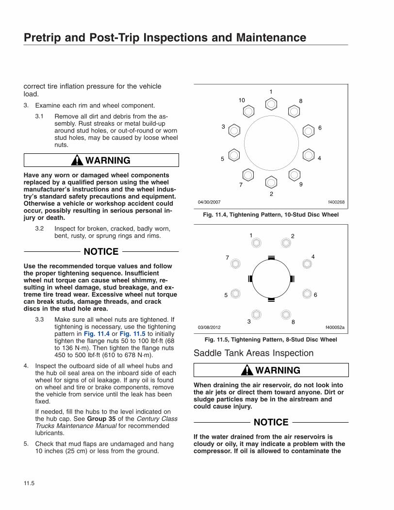
correct tire inflation pressure for the vehicleload.
3. Examine each rim and wheel component.
3.1 Remove all dirt and debris from the as-sembly. Rust streaks or metal build-uparound stud holes, or out-of-round or wornstud holes, may be caused by loose wheelnuts.
WARNINGHave any worn or damaged wheel componentsreplaced by a qualified person using the wheelmanufacturer’s instructions and the wheel indus-try’s standard safety precautions and equipment.Otherwise a vehicle or workshop accident couldoccur, possibly resulting in serious personal in-jury or death.
3.2 Inspect for broken, cracked, badly worn,bent, rusty, or sprung rings and rims.
NOTICEUse the recommended torque values and followthe proper tightening sequence. Insufficientwheel nut torque can cause wheel shimmy, re-sulting in wheel damage, stud breakage, and ex-treme tire tread wear. Excessive wheel nut torquecan break studs, damage threads, and crackdiscs in the stud hole area.
3.3 Make sure all wheel nuts are tightened. Iftightening is necessary, use the tighteningpattern in Fig. 11.4 or Fig. 11.5 to initiallytighten the flange nuts 50 to 100 lbf·ft (68to 136 N·m). Then tighten the flange nuts450 to 500 lbf·ft (610 to 678 N·m).
4. Inspect the outboard side of all wheel hubs andthe hub oil seal area on the inboard side of eachwheel for signs of oil leakage. If any oil is foundon wheel and tire or brake components, removethe vehicle from service until the leak has beenfixed.
If needed, fill the hubs to the level indicated onthe hub cap. See Group 35 of the Century ClassTrucks Maintenance Manual for recommendedlubricants.
5. Check that mud flaps are undamaged and hang10 inches (25 cm) or less from the ground.
Saddle Tank Areas Inspection
WARNINGWhen draining the air reservoir, do not look intothe air jets or direct them toward anyone. Dirt orsludge particles may be in the airstream andcould cause injury.
NOTICEIf the water drained from the air reservoirs iscloudy or oily, it may indicate a problem with thecompressor. If oil is allowed to contaminate the
f400268
1
10 8
6
4
9
2
7
5
3
04/30/2007
Fig. 11.4, Tightening Pattern, 10-Stud Disc Wheel
f400052a
1 2
3
4
5 6
7
803/08/2012
Fig. 11.5, Tightening Pattern, 8-Stud Disc Wheel
Pretrip and Post-Trip Inspections and Maintenance
11.5
air dryer, it will not remove the water from the airbrake system, which could adversely affect brak-ing.
1. Drain the brake system air reservoirs (reservoirswithout automatic drain valves only).
WARNINGNever operate the engine with the fuel tank shut-off valves partially closed. This could damage thefuel pump, causing sudden loss of engine power,possibly resulting in serious personal injury dueto reduced vehicle control.
2. Ensure that fuel tanks are secured to theirmounting brackets and that the mountingbrackets are secured to the frame.
If equipped with fuel tank shutoff valves, be surethe valves are fully open.
3. Inspect visible frame rails for missing bolts, shinyareas, or rust streaks. Check all visible cross-members for damage or signs of looseness.
4. Inspect visible components of the exhaust sys-tem to ensure connections are tight.
Inspect upstream of the aftertreatment device(ATD), if equipped, for cracking or signs of leaks,such as soot trails. Inspect downstream of theATD for signs of exhaust leaks, such as blister-ing or warping of nearby components.
Engine Compartment Inspection1. Check the ground underneath the engine for fuel,
oil, or coolant leaks.
2. Inspect the air intake system for leaks or dam-age.
NOTICEFailure to maintain a sealed air intake systemcould allow the entry of dirt and contaminantsinto the engine. This could adversely affect en-gine performance and result in engine damage.
2.1 Push the reset button on the air intakerestriction indicator located on the aircleaner, if equipped.
2.2 Check the air intake duct from the aircleaner to the engine intake. Make surethe duct components are secure and air-tight.
3. Check the engine oil level.
NOTICEOperating the engine with the oil level below theminimum fill (or "add") mark or above the maxi-mum fill (or "full") mark could result in enginedamage.
3.1 Check the oil level with the vehicle parkedon a level surface. See the engine manu-facturer’s guidelines for engine shutdowntime requirements prior to checking the oillevel.
IMPORTANT: On engines that comply withEPA07 regulations, use CJ-4 engine oil withless than 1% sulfated ash. Failure to useCJ-4 oil may void the warranty on emissionaftertreatment components.
3.2 If the oil level is at or below the minimumfill (or "add") mark on the dipstick, addenough oil to maintain the level betweenthe minimum and maximum fill marks. Seethe engine operation manual for recom-mended lubricants.
4. Check the power steering reservoir fluid level.
The power steering fluid level should be betweenthe MIN COLD mark and the middle mark justabove it. See Fig. 11.6. If needed, fill the reser-voir with automatic transmission fluid that meetsDexron III or TES-389 specifications.
NOTICELow coolant could result in engine overheating,which could cause engine damage.
IMPORTANT: The surge tank must be cool tocheck the coolant level.
5. Check the engine coolant level in the radiatorsurge tank. See Fig. 11.7.
Pretrip and Post-Trip Inspections and Maintenance
11.6

NOTICECoolant must be filled to the COLD MAX line ofthe surge tank. Low coolant could result in en-gine overheating, which could cause engine dam-age.
5.1 If the coolant is low, fill the surge tank tothe MAX line with a 50/50 mixture of waterand the type of antifreeze currently in-stalled in the vehicle.
5.2 If the surge tank was empty, start the en-gine after refilling and check the levelagain when the engine is at operatingtemperature.
6. Inspect visible engine wiring for damage orlooseness. Check for loose wiring, chafed insula-tion, and damaged or loose hold-down clamps.
7. Inspect visible frame rails for missing bolts, shinyareas, or rust streaks.
Cab Inspection1. Push the reset button on the dash-mounted air
intake restriction indicator, if equipped.
2. With the ignition switch in the OFF position,check the air-pressure warning system.
2.1 If not previously drained, drain the air res-ervoirs using moderate brake applicationsuntil pressure in both reservoirs is lessthan 70 psi (483 kPa).
2.2 Turn the ignition to the ON position. Theinstrument cluster will complete a fullgauge sweep and bulb check, and an au-dible warning will sound. Ensure the lowair pressure lamp (BRAKE AIR) remainsilluminated and an audible warning contin-ues to sound after the gauge sweep iscomplete.
3. Check air governor cut-in and cut-out pressures.
3.1 Start the engine and ensure the BRAKEAIR lamp goes out and the buzzer si-lences when pressure reaches approxi-mately 70 psi (483 kPa) in both air reser-voirs.
The air governor should cut out at ap-proximately 120 psi (827 kPa). For ve-hicles with an optional dryer reservoirmodule (DRM), the cut-out pressure isapproximately 130 psi (896 kPa).
3.2 With the engine idling, apply the brakepedal several times. The air governorshould cut in when pressure in the primaryair reservoir (top air gauge) reaches ap-proximately 100 psi (690 kPa).
4. Check air pressure build-up time.
05/21/2007
1
f462079
NOTE: Typical reservoir shown; configurations mayvary.1. Filler Cap
Fig. 11.6, Power Steering Fluid Reservoir
1
2
f500390
3
4
4
02/05/2013
5
1. Pressure Relief Cap2. Filler Cap3. COLD MAX Fill Line
4. COLD MIN Fill Line5. Coolant Level Sensor
Fig. 11.7, Coolant Surge Tank
Pretrip and Post-Trip Inspections and Maintenance
11.7
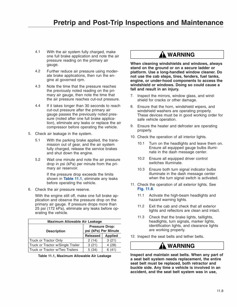
4.1 With the air system fully charged, makeone full brake application and note the airpressure reading on the primary airgauge.
4.2 Further reduce air pressure using moder-ate brake applications, then run the en-gine at governed rpm.
4.3 Note the time that the pressure reachesthe previously noted reading on the pri-mary air gauge, then note the time thatthe air pressure reaches cut-out pressure.
4.4 If it takes longer than 30 seconds to reachcut-out pressure after the primary airgauge passes the previously noted pres-sure (noted after one full brake applica-tion), eliminate any leaks or replace the aircompressor before operating the vehicle.
5. Check air leakage in the system.
5.1 With the parking brake applied, the trans-mission out of gear, and the air systemfully charged, release the service brakesand shut down the engine.
5.2 Wait one minute and note the air pressuredrop in psi (kPa) per minute from the pri-mary air reservoir.
If the pressure drop exceeds the limitsshown in Table 11.1, eliminate any leaksbefore operating the vehicle.
6. Check the air pressure reserve.
With the engine still off, make one full brake ap-plication and observe the pressure drop on theprimary air gauge. If pressure drops more than25 psi (172 kPa), eliminate any leaks before op-erating the vehicle.
Maximum Allowable Air Leakage
DescriptionPressure Drop:
psi (kPa) Per MinuteReleased Applied
Truck or Tractor Only 2 (14) 3 (21)Truck or Tractor w/Single Trailer 3 (21) 4 (28)Truck or Tractor w/Two Trailers 5 (34) 6 (41)
Table 11.1, Maximum Allowable Air Leakage
WARNINGWhen cleaning windshields and windows, alwaysstand on the ground or on a secure ladder orplatform. Use a long-handled window cleaner. Donot use the cab steps, tires, fenders, fuel tanks,engine, or under-hood components to access thewindshield or windows. Doing so could cause afall and result in an injury.
7. Inspect the mirrors, window glass, and wind-shield for cracks or other damage.
8. Ensure that the horn, windshield wipers, andwindshield washers are operating properly.These devices must be in good working order forsafe vehicle operation.
9. Ensure the heater and defroster are operatingproperly.
10. Check the operation of all interior lights.
10.1 Turn on the headlights and leave them on.Ensure all equipped gauge bulbs illumi-nate in the dash message center.
10.2 Ensure all equipped driver controlswitches illuminate.
10.3 Ensure both turn signal indicator bulbsilluminate in the dash message centerwhen the turn signal switch is activated.
11. Check the operation of all exterior lights. SeeFig. 11.8.
11.1 Activate the high-beam headlights andhazard warning lights.
11.2 Exit the cab and check that all exteriorlights and reflectors are clean and intact.
11.3 Check that the brake lights, taillights,headlights, turn signals, marker lights,identification lights, and clearance lightsare working properly.
12. Inspect the seat belts and tether belts.
WARNINGInspect and maintain seat belts. When any part ofa seat belt system needs replacement, the entireseat belt must be replaced, both retractor andbuckle side. Any time a vehicle is involved in anaccident, and the seat belt system was in use,
Pretrip and Post-Trip Inspections and Maintenance
11.8

the entire vehicle seat belt system must be re-placed before operating the vehicle. Do not at-tempt to modify the seat belt system; doing socould change the effectiveness of the system.Failure to replace worn or damaged seat belts, ormaking any modifications to the system, may re-sult in personal injury or death.
12.1 Check the web for fraying, cuts, extremedirt and dust, or for severe fading fromexposure to sunlight, especially near thebuckle latch plate and in the D-loop guidearea.
12.2 Check operation of the buckle, latch, Kom-fort Latch or Sliding Komfort Latch (ifequipped), web retractor, and upper seatbelt mount on the door pillar. Check allvisible components for wear or damage.
12.3 Check the seat belt and tether belt con-nection points and tighten any that areloose.
WARNINGNever fill fuel tanks to more than 95 percent oftheir liquid capacity. This could make them morelikely to rupture from impact, possibly causing
fire and resulting in serious personal injury ordeath by burning.
Do not mix gasoline or alcohol with diesel fuel.This mixture could cause an explosion, possiblyresulting in serious personal injury or death. Donot fill the fuel tanks in the presence of sparks,open flames, or intense heat. These could ignitethe fuel, possibly causing severe burns.
IMPORTANT: On engines that comply withEPA07 regulations, use ultralow-sulfur diesel(ULSD) with 15 ppm sulfur content or less. Fail-ure to use ULSD fuel may void the warranty onemission components.
13. Check the fuel level in the fuel tank(s). To keepcondensation to a minimum, fuel tanks should befilled at the end of each day.
14. Adjust the rearview and down view mirrors asnecessary.
15. Test the service brakes.
15.1 With the engine running and air systemfully charged, set the parking brake.
15.2 Put the vehicle in the lowest gear andgently attempt to move it forward. The ve-hicle should not move.
If the vehicle moves, the parking brakesare not operating correctly and must berepaired before the vehicle is operated.
16. Test the backup alarm.
16.1 Release the parking brake and put thetransmission in reverse.
16.2 Move the vehicle slightly backward to en-sure that the backup alarm is operatingcorrectly.
Weekly Post-Trip Inspectionand MaintenanceEngine Compartment Inspection
WARNINGWasher fluids may be flammable and poisonous.Do not expose washer fluid to an open flame orany burning material, such as a cigarette. Always
9/07/95 f600903
1 2
3456
7
1. Identification Lights2. Clearance Lights3. Daytime Running
Lights4. Road Lights
5. Headlights6. Turn Signals and
Side-Marker Lights7. Marker Lights
Fig. 11.8, Exterior Lights
Pretrip and Post-Trip Inspections and Maintenance
11.9

comply with the washer fluid manufacturer’s rec-ommended safety precautions.
1. Check the windshield washer reservoir fluid level.
2. After resetting the air intake restriction indicatorduring the daily pretrip inspection, check the indi-cator again with the engine off.
2.1 Check an indicator with graduations to seeif air restriction exceeds the value shownin Table 11.2.
Check a go/no-go indicator without gradu-ations to see if the colored bar showsthrough the clear window.
Air Intake Maximum Restriction Values: (inH 2O)
Engine Make Pre-EPA07Engines EPA07 Engines
Caterpillar 25 —Cummins 25 25Detroit™ 20 22Mercedes-Benz 22 22
Table 11.2, Air Intake Maximum Restriction Values
2.2 If air restriction exceeds the maximum al-lowable value, operate the vehicle for onemore day, making sure not to run the en-gine over rated rpm. Refer to the engineoperation manual for more information onrated rpm for your engine.
2.3 If air restriction exceeds the maximumvalue again, replace the air cleaner ele-ment. For instructions, refer to Group 09of the Century Class Trucks WorkshopManual.
3. If the vehicle is equipped with an Allison auto-matic transmission, check the automatic trans-mission fluid level.
4. Check for water in the fuel/water separator, ifequipped.
IMPORTANT: When draining fluid from afuel/water separator, drain the fluid into anappropriate container and dispose of it prop-erly. Many jurisdictions now issue fines fordraining fuel/water separators onto theground.
4.1 Place a suitable container under the fuel/water separator.
NOTE: A hose may be used to direct waterinto the container. Use a hose with a ½-inchpipe thread on DAVCO models.
4.2 If the engine is equipped with a built-inwater separator, loosen the drain valve,and allow the water to run out. Close thedrain valve, taking care not to overtightenit.
4.3 Alliance/Racor Models: Turn the drain plugcounterclockwise to open it. See Fig. 11.9.
DAVCO Models: Remove the vent capand open the drain. See Fig. 11.10.
IMPORTANT: Water in the fuel/water separa-tor will appear as beads. Drain the fuel/waterseparator only enough to remove the water.Stop draining fluid when fuel begins to drainout. If the fuel/water separator is drained offuel, it will be necessary to prime the fuel
02/03/2010 f470552
1
2
34
56
7
8
9
10
11
1. Washers (qty 2)2. Nuts (qty 2)3. Frame Rail4. Fuel Outlet Port5. Fuel Inlet Port6. Priming Pump
7. Mounting Head8. Mounting Bolts (qty 2)9. Filter Element10. Sight Bowl11. Drain Plug
Fig. 11.9, Alliance Fuel/Water Separator Assembly andInstallation
Pretrip and Post-Trip Inspections and Maintenance
11.10
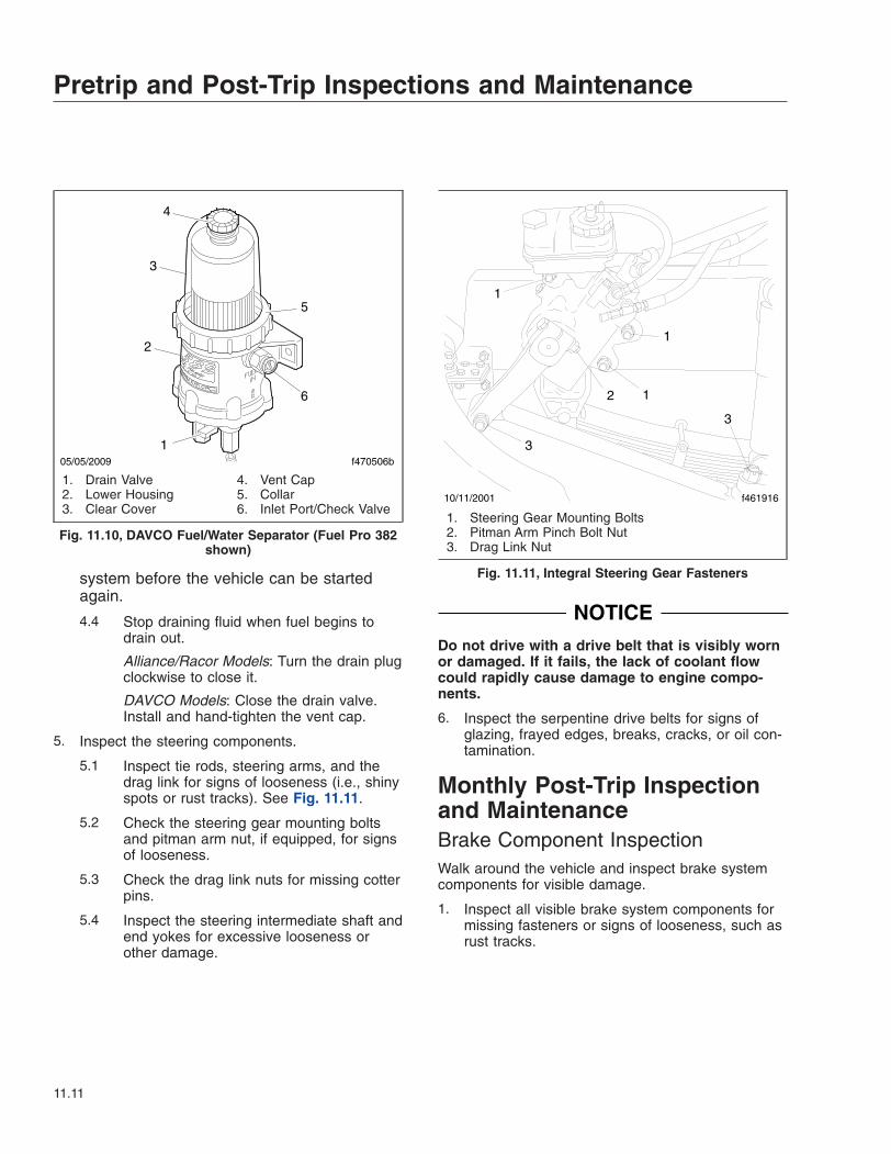
system before the vehicle can be startedagain.
4.4 Stop draining fluid when fuel begins todrain out.
Alliance/Racor Models: Turn the drain plugclockwise to close it.
DAVCO Models: Close the drain valve.Install and hand-tighten the vent cap.
5. Inspect the steering components.
5.1 Inspect tie rods, steering arms, and thedrag link for signs of looseness (i.e., shinyspots or rust tracks). See Fig. 11.11.
5.2 Check the steering gear mounting boltsand pitman arm nut, if equipped, for signsof looseness.
5.3 Check the drag link nuts for missing cotterpins.
5.4 Inspect the steering intermediate shaft andend yokes for excessive looseness orother damage.
NOTICEDo not drive with a drive belt that is visibly wornor damaged. If it fails, the lack of coolant flowcould rapidly cause damage to engine compo-nents.
6. Inspect the serpentine drive belts for signs ofglazing, frayed edges, breaks, cracks, or oil con-tamination.
Monthly Post-Trip Inspectionand MaintenanceBrake Component InspectionWalk around the vehicle and inspect brake systemcomponents for visible damage.
1. Inspect all visible brake system components formissing fasteners or signs of looseness, such asrust tracks.
f470506b05/05/2009
4
1
3
5
2
6
1. Drain Valve2. Lower Housing3. Clear Cover
4. Vent Cap5. Collar6. Inlet Port/Check Valve
Fig. 11.10, DAVCO Fuel/Water Separator (Fuel Pro 382shown)
10/11/2001 f461916
1
1
1
2
3
3
1. Steering Gear Mounting Bolts2. Pitman Arm Pinch Bolt Nut3. Drag Link Nut
Fig. 11.11, Integral Steering Gear Fasteners
Pretrip and Post-Trip Inspections and Maintenance
11.11

NOTICEIf the external breather tube or breather cap ismissing or incorrectly installed, road dirt and de-bris can adversely affect the operation of thebrake chamber. Once inside of the chamber, dirtand debris can cause the internal parts of thechamber to deteriorate faster.
2. Inspect the exterior surfaces of brake chambersfor damage. Make sure that breather holes areopen and free of debris.
NOTE: Do not route air brake lines on top ofanything likely to be stepped on.
3. Inspect air brake lines for dents, swelling, kinks,twisting, abrasion, and damage, especially nearmoving parts.
4. Inspect flex air lines for deterioration or signs ofabrasion.
5. Inspect for cracked, worn, or oil-contaminatedbrake linings and brake drums (or rotors).
6. Check the thickness of the brake linings. Re-place brake linings on all brake assemblies onthe axle if any brake linings are worn to less thanapproximately 1/4 inch (6.4 mm) at the thinnestpoint.
Saddle Tank Areas Inspection
WARNINGWhen draining the air reservoir, do not look intothe air jets or direct them toward anyone. Dirt orsludge particles may be in the airstream andcould cause injury.
NOTICEIf the water drained from the air reservoirs iscloudy or oily, it may indicate a problem with thecompressor. If oil is allowed to contaminate theair dryer, it will not remove the water from the airbrake system, which could adversely affect brak-ing.
1. Drain the brake system air reservoirs (reservoirswith automatic drain valves only).
NOTE: Battery locations vary between vehicles.
2. Inspect the batteries.
WARNINGBattery posts, terminals, and related accessoriescontain lead and lead compounds, chemicalsknown to the State of California to cause cancerand reproductive harm. To prevent possible per-sonal injury, always wash your hands after han-dling battery parts and related accessories.
2.1 Remove the battery box cover and inspectall visible battery cables for loose wiring ordamage.
2.2 Check that the battery hold-down is se-cure.
Engine Compartment Inspection andAdjustments1. Check the hydraulic clutch reservoir, if equipped.
If necessary, add DOT 4 brake fluid.
2. Inspect the radiator and heater hoses, includingthe clamps and support brackets.
2.1 Inspect the radiator and charge air coolerfor damage and accumulated debris.Straighten bent or damaged fins to permitairflow across all areas of the cores.
NOTE: When traveling through areas of highinsect concentration, it may be necessary toclean the exterior of the radiator or thecharge air cooler core as often as every 200miles (322 km).
2.2 Make sure the radiator inlet and outlethoses are pliable and are not cracking orballooning.
2.3 Make sure the heater hoses are pliableand are not cracking or ballooning.
2.4 Tighten hose clamps as necessary.
IMPORTANT: Do not overtighten hoseclamps, as hose life can be adversely af-fected.
2.5 Ensure hose support brackets are se-curely fastened. Make sure hoses are notlocated near sources of wear, abrasion, orhigh heat.
Pretrip and Post-Trip Inspections and Maintenance
11.12

IMPORTANT: When replacing hoses, installservice-type knitted or braided-yarn reinforcedneoprene hose. Extended-service-life siliconehoses may also be used. See the Alliance PartsCatalog at www.alliancebrandparts.com orcontact a Freightliner Dealer.
3. Check the steering wheel for excessive play.
3.1 Start the engine. With the front tiresstraight ahead, turn the steering wheeluntil motion is observed at the frontwheels.
3.2 Align a reference mark on the steeringwheel to a rule, then slowly turn the steer-ing wheel in the opposite direction untilmotion is again detected at the wheels.
3.3 Measure the lash (free play) at the rim ofthe steering wheel. Excessive lash existsif steering wheel movement exceeds 2-1/2inches (64 mm) with a 20-inch (508-mm)steering wheel, or 2-1/4 inches (57 mm)with an 18-inch (457-mm) steering wheel.
3.4 If there is excessive lash, check the steer-ing system for wear or incorrect adjust-ment before operating the vehicle.
Pretrip and Post-Trip Inspections and Maintenance
11.13
12
Cab AppearanceCab Washing and Polishing . . . . . . . . . . . . . . . . . . . . . . . . . . . . . . . . . . . . . . . . . . . . . . . . . . . . . . . . 12.1Care of Fiberglass Parts . . . . . . . . . . . . . . . . . . . . . . . . . . . . . . . . . . . . . . . . . . . . . . . . . . . . . . . . . . 12.1Care of Chrome Parts . . . . . . . . . . . . . . . . . . . . . . . . . . . . . . . . . . . . . . . . . . . . . . . . . . . . . . . . . . . . 12.1Care of Exterior Lights . . . . . . . . . . . . . . . . . . . . . . . . . . . . . . . . . . . . . . . . . . . . . . . . . . . . . . . . . . . . 12.1Dashboard Care . . . . . . . . . . . . . . . . . . . . . . . . . . . . . . . . . . . . . . . . . . . . . . . . . . . . . . . . . . . . . . . . . 12.1Vinyl Upholstery Cleaning . . . . . . . . . . . . . . . . . . . . . . . . . . . . . . . . . . . . . . . . . . . . . . . . . . . . . . . . . 12.2Velour Upholstery Cleaning . . . . . . . . . . . . . . . . . . . . . . . . . . . . . . . . . . . . . . . . . . . . . . . . . . . . . . . . 12.2

Cab Washing and PolishingTo protect the finish of your new vehicle, follow theseguidelines carefully:
• During the first 30 days, rinse your vehicle fre-quently with water. If the vehicle is dirty, use amild liquid soap. Do not use detergent.
• During the first 30 days, do not use anythingabrasive on your vehicle. Brushes, chemicals,and cleaners may scratch the finish.
• During the first 120 days, do not wax yourvehicle.
To extend the life of your vehicle’s finish, follow theseguidelines:
• Avoid washing your vehicle in the hot sun.
• Always use water. After the cab is completelywashed, dry it with a towel or chamois.
• Do not dust painted surfaces with a dry cloth,as this will scratch the paint.
• Do not remove ice or snow from a painted sur-face with a scraper of any sort.
• To prevent damage to the finish, wax it regu-larly. Before waxing, if the finish has becomedull, remove oxidized paint using a cleanerspecifically designed for this purpose. Removeall road tar and tree sap before waxing.Freightliner recommends that a quality brand ofcleaner or cleaner-polish and polishing wax beused.
• Do not let diesel fuel or antifreeze stand on apainted surface. If either should occur, rinsethe surface off with water.
• To prevent rust, have any nicks or other dam-age on the finish touched up as soon as pos-sible.
• Park your vehicle in a sheltered area wheneverpossible.
Care of Fiberglass PartsWash unpainted fiberglass air fairings and shieldsmonthly with a mild detergent, such as dishwashingliquid. Avoid strong alkaline cleansers.
Apply a wax specifically designed for fiberglass.
Care of Chrome PartsTo prevent rust, keep chrome parts clean and pro-tected at all times. This is especially important duringwinter driving and in coastal areas where there isexposure to salt air.
When cleaning chrome parts, use clean water and asoft cloth or sponge. A mild detergent may also beused.
Sponge gently, then rinse. If necessary, use a non-abrasive chrome cleaner to remove stubborn rust orother material. Do not use steel wool.
To help protect the chrome after cleaning, apply acoat of polishing wax to the surface. Never use waxon parts that are exposed to high heat, such as ex-haust pipes.
Care of Exterior LightsClean the headlight lenses by hand only, using aflannel cloth with mild, non-caustic soap or detergent,and water.
CAUTIONDo not use a power buffer, paper towels, chemi-cal solvents, or abrasive cleaners on the head-light lens, all of which can remove the UV coatingfrom the surface, and result in yellowing of thelens.
Dashboard Care
NOTICEWhen cleaning the dashboard, instrument panel,or gauge lens covers, do not use Armor-All Pro-tectant®, STP Son-of-a-Gun®, window cleaner, orother equivalent treatments. These cleaners con-tain vinyl plasticizers which can cause stresscrazing in the interior plastic panels and can re-sult in cracking of the panels. Some cleaners canalso have an adverse effect on the clear plasticof instrument panels and gauge lens covers, re-sulting in a foggy or cloudy appearance. Thistype of damage is not covered by vehicle war-ranty.
To clean the dashboard, instrument panel, and gaugelens covers, use a cloth dampened with warm soapy
Cab Appearance
12.1
water. Make certain to wring the cloth out well beforecleaning, as excess water will damage the electricalcomponents.
Vinyl Upholstery CleaningTo prevent soiling, frequent vacuuming or light brush-ing to remove dust and dirt is recommended. Harshcleaning agents can cause permanent damage tovinyl upholstery. To preserve the upholstery and pre-vent damage, carefully review the following sectionsfor recommended cleaning procedures. Waxing orrefinishing improves soil resistance and cleanabilityfor all vinyls. Any hard wax, such as that used onautomobiles, may be used.
Ordinary DirtWash the upholstery with warm water and mild soap,such as saddle or oil soap. Apply soapy water to alarge area and allow to soak for a few minutes, thenrub briskly with a cloth to remove the dirt. This canbe repeated several times, as necessary.
If dirt is deeply imbedded, use a soft bristle brushafter applying the soap.
If dirt is extremely difficult to remove, wall-washingpreparations normally found around the home can beused. Powdered cleaners, such as those used forsinks and tiles, are abrasive and must be used withcaution as they can scratch the vinyl or give it a per-manent dull appearance.
Chewing GumHarden the gum with an ice cube wrapped in a plas-tic bag, then scrape it off with a dull knife. Any re-maining traces of gum can be removed with an all-purpose light oil (peanut butter will also work) andwiped off.
Tars, Asphalts, and CreosoteEach of these items stains vinyl after prolonged con-tact. They should be wiped off immediately and thearea carefully cleaned, using a cloth dampened withnaphtha.
Paint, Shoe Heel MarksPaint should be removed immediately. Do not usepaint remover or liquid-type brush cleaner on vinyl.An unprinted cloth, dampened with naphtha or tur-
pentine may be used. Use care to prevent contactwith parts of the upholstery that are not vinyl.
Sulfide StainsSulfide compounds, such as those found in eggs andsome canned goods, can stain after prolonged con-tact with vinyl. These stains can be removed by plac-ing a clean, unprinted piece of cloth over the spottedarea and pouring a liberal amount of 6 percent hy-drogen peroxide onto the cloth. Allow the saturatedcloth to remain on the spot for 30 to 60 minutes. Forstubborn spots, allow the hydrogen-peroxide satu-rated cloth to remain on the area overnight. Use cau-tion to prevent the solution from seeping into theseams, or it will weaken the cotton thread.
Nail Polish and Nail Polish RemoverProlonged contact with these substances causes per-manent damage to vinyl. Careful blotting immediatelyafter contact minimizes damage. Do not spread theliquid during removal.
Shoe PolishMost shoe polishes contain dyes which penetratevinyl and stain it permanently. Shoe polish should bewiped off as quickly as possible using naphtha orlighter fluid. If staining occurs, try the procedure usedfor sulfide stains.
Ball Point InkBall point ink can sometimes be removed if rubbedimmediately with a damp cloth, using water or rub-bing alcohol. If this does not work, try the procedureused for sulfide stains.
MiscellaneousIf stains do not respond to any of the treatments de-scribed above, it is sometimes helpful to expose thevinyl to direct sunlight for up to 30 hours. Mustard,ball point ink, certain shoe polishes, and dyes oftenbleach out in direct sunlight, leaving the vinyl undam-aged.
Velour Upholstery CleaningTo prevent soiling, frequent vacuuming or light brush-ing to remove dust and dirt is recommended. Spotclean with a mild solvent or an upholstery shampoo,
Cab Appearance
12.2
or the foam from a mild detergent. When using a sol-vent or a dry-cleaning product, follow the instructionscarefully, and clean only in a well-ventilated area.Avoid any product that contains carbon tetrachlorideor other toxic materials. With either method, pretest asmall area before proceeding. Use a professionalupholstery cleaning service when extensive cleaningis needed.
Grease and Oil-Based StainsDampen a small absorbent cloth with dry-cleaningsolvent or spot remover. Apply the cloth carefully tothe spot from the outer edge to the center. Pat andblot the spot with a clean, dry cloth. Repeat severaltimes, as necessary, turning the cloths so that thestain does not redeposit on the fabric.
Sugar and Water-Based StainsApply water-based detergent or cleaner, working incircular motions. Pat and blot as dry as possible. Re-peat, if necessary, before drying thoroughly.
Chewing Gum or WaxHarden the gum or wax with an ice cube wrapped ina plastic bag, then scrape it off with a dull knife. Ex-cess wax can be absorbed by placing a thick whiteblotter over the wax and heating with a warm (nothot) iron. Remove the remainder by using the proce-dure for grease and oil-based stains.
MildewBrush the dry fabric with a soft brush. Sponge withdetergent, and blot. If the fabric is colorfast, dilute ateaspoon of bleach in one quart (one liter) of coolwater. Apply with a swab, directly on the mildewstain. Dab repeatedly with clear, cool water, and blotdry.
Cab Appearance
12.3
13
In an EmergencyHazard Warning Lights . . . . . . . . . . . . . . . . . . . . . . . . . . . . . . . . . . . . . . . . . . . . . . . . . . . . . . . . . . . . 13.1Fire Extinguisher . . . . . . . . . . . . . . . . . . . . . . . . . . . . . . . . . . . . . . . . . . . . . . . . . . . . . . . . . . . . . . . . . 13.1Emergency Kit, Optional . . . . . . . . . . . . . . . . . . . . . . . . . . . . . . . . . . . . . . . . . . . . . . . . . . . . . . . . . . 13.1Towing . . . . . . . . . . . . . . . . . . . . . . . . . . . . . . . . . . . . . . . . . . . . . . . . . . . . . . . . . . . . . . . . . . . . . . . . . 13.1Emergency Starting With Jumper Cables . . . . . . . . . . . . . . . . . . . . . . . . . . . . . . . . . . . . . . . . . . . . . 13.3Fire in the Cab . . . . . . . . . . . . . . . . . . . . . . . . . . . . . . . . . . . . . . . . . . . . . . . . . . . . . . . . . . . . . . . . . . 13.4
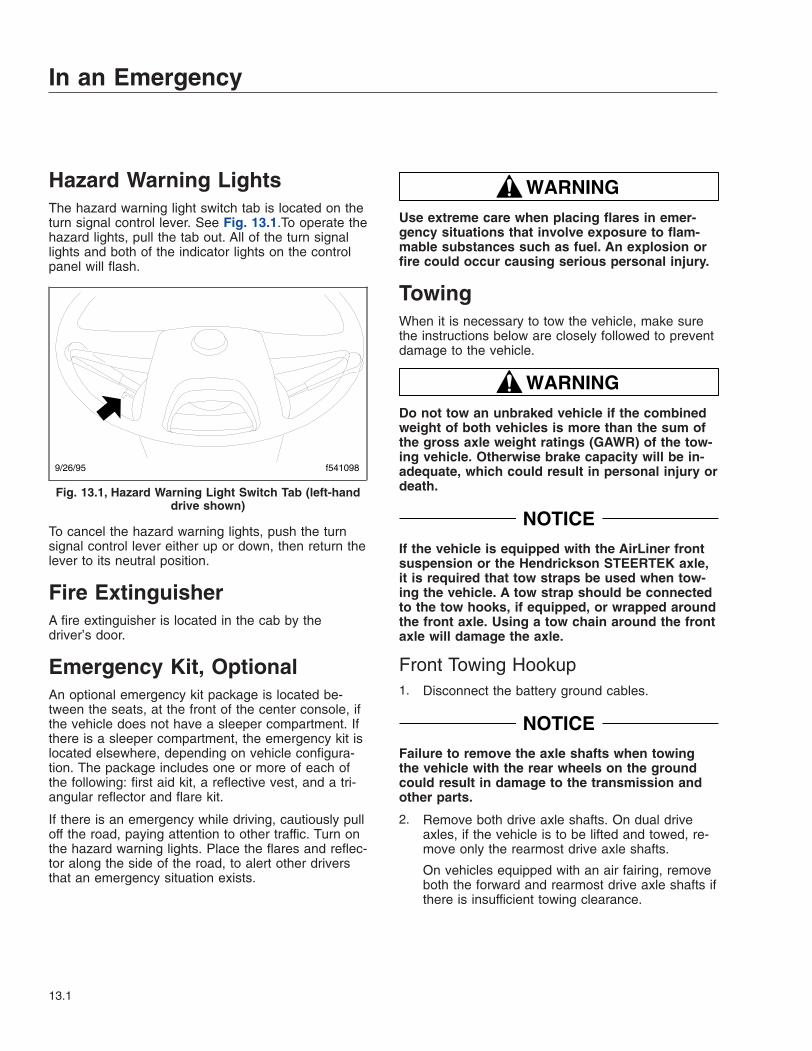
Hazard Warning LightsThe hazard warning light switch tab is located on theturn signal control lever. See Fig. 13.1.To operate thehazard lights, pull the tab out. All of the turn signallights and both of the indicator lights on the controlpanel will flash.
To cancel the hazard warning lights, push the turnsignal control lever either up or down, then return thelever to its neutral position.
Fire ExtinguisherA fire extinguisher is located in the cab by thedriver’s door.
Emergency Kit, OptionalAn optional emergency kit package is located be-tween the seats, at the front of the center console, ifthe vehicle does not have a sleeper compartment. Ifthere is a sleeper compartment, the emergency kit islocated elsewhere, depending on vehicle configura-tion. The package includes one or more of each ofthe following: first aid kit, a reflective vest, and a tri-angular reflector and flare kit.
If there is an emergency while driving, cautiously pulloff the road, paying attention to other traffic. Turn onthe hazard warning lights. Place the flares and reflec-tor along the side of the road, to alert other driversthat an emergency situation exists.
WARNINGUse extreme care when placing flares in emer-gency situations that involve exposure to flam-mable substances such as fuel. An explosion orfire could occur causing serious personal injury.
TowingWhen it is necessary to tow the vehicle, make surethe instructions below are closely followed to preventdamage to the vehicle.
WARNINGDo not tow an unbraked vehicle if the combinedweight of both vehicles is more than the sum ofthe gross axle weight ratings (GAWR) of the tow-ing vehicle. Otherwise brake capacity will be in-adequate, which could result in personal injury ordeath.
NOTICEIf the vehicle is equipped with the AirLiner frontsuspension or the Hendrickson STEERTEK axle,it is required that tow straps be used when tow-ing the vehicle. A tow strap should be connectedto the tow hooks, if equipped, or wrapped aroundthe front axle. Using a tow chain around the frontaxle will damage the axle.
Front Towing Hookup1. Disconnect the battery ground cables.
NOTICEFailure to remove the axle shafts when towingthe vehicle with the rear wheels on the groundcould result in damage to the transmission andother parts.
2. Remove both drive axle shafts. On dual driveaxles, if the vehicle is to be lifted and towed, re-move only the rearmost drive axle shafts.
On vehicles equipped with an air fairing, removeboth the forward and rearmost drive axle shafts ifthere is insufficient towing clearance.
9/26/95 f541098
Fig. 13.1, Hazard Warning Light Switch Tab (left-handdrive shown)
In an Emergency
13.1

3. Cover the ends of the hubs with metal plates orplywood cut to fit the axle opening, and drilled tofit the axle shaft studs. This prevents lubricantfrom leaking out, and will keep contaminantsfrom getting into and damaging the wheel bear-ings and axle lubricant.
NOTICEFailure to protect the frame rails from the chainscould cause damage, leading to eventual framefailure.
4. On dual drive axles, if the vehicle is to be liftedand towed, chain the forward rear-axle assemblyto the vehicle frame. Use protection to keep thechains from damaging the frame.
5. Remove the bumper extension and chrome bum-per, if so equipped. Remove the bumper fairing,if so equipped.
6. On vehicles equipped with an air fairing, adjustthe trim tab to the lowest position.
NOTICEDo not pass a sling (for example, a rope or chain)from one tow hook to another to fasten for tow-ing (see Fig. 13.2). Known as reeving, this prac-tice is not permissible in most industrial applica-tions of towing and hoisting. Reeving canoverload the hooks and result in damage to thevehicle.
7. Attach the towing device. Due to the many vari-ables that exist in towing, positioning the liftingand towing device is the sole responsibility of thetowing-vehicle operator.
8. On vehicles equipped with an air fairing, mea-sure the distance from the ground to the bumper,or from the ground to a frame bracket.
9. Lift the vehicle, and secure the safety chains. Ifextra towing clearance is needed, remove thefront wheels.
WARNINGFailure to lower the vehicle could result in the airfairing striking an overhead obstruction, such asa bridge or overpass, and causing vehicle dam-age or personal injury.
10. On vehicles equipped with an air fairing, repeatthe measurement taken in step 8. The differencebetween the two measurements must not exceed14 inches (36 cm). If necessary, lower the ve-hicle.
11. Connect the clearance lights, taillights, and sig-nal lights. Connect any special towing lights re-quired by local regulations.
WARNINGFailure to chock the tires or connect the towtruck’s air brake system before releasing thespring parking brakes could allow the disabledvehicle to suddenly roll. This could cause prop-erty damage or personal injury.
12. Chock the disabled vehicle’s tires, and connectthe towing vehicle’s air brake system to the ve-hicle being towed. Then, release the spring park-ing brakes and remove the chocks.
Rear Towing Hookup
NOTICEUsing a rear towing hookup on a vehicleequipped with a roof fairing could cause damageto the cab structure.
If reverse towing at speeds above 45 mph (70kph) is necessary, hold down the cab with ten-sion straps looped over the cab shocks andunder the frame rails. Failure to do so couldallow the wind load to lift the cab unexpectedly,resulting in damage to the air springs and othercomponents.
1. If the vehicle is equipped with cab air suspen-sion, and reverse towing at speeds above 45mph (70 kph) is necessary, hold down the cab asfollows:
1.1 Drain the air from the cab air springs.
1.2 Loop a 2-inch (5-cm) ratchet-style tensionstrap (rated 2000 lb [900 kg] minimumwork load) over the top of the cab shockand under the frame rail. Tighten the strapfor a snug fit. If the cab is equipped withtwo or more shocks, restrain the aftmostshock on each side of the vehicle.
In an Emergency
13.2
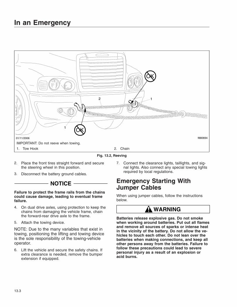
2. Place the front tires straight forward and securethe steering wheel in this position.
3. Disconnect the battery ground cables.
NOTICEFailure to protect the frame rails from the chainscould cause damage, leading to eventual framefailure.
4. On dual drive axles, using protection to keep thechains from damaging the vehicle frame, chainthe forward-rear drive axle to the frame.
5. Attach the towing device.
NOTE: Due to the many variables that exist intowing, positioning the lifting and towing deviceis the sole responsibility of the towing-vehicleoperator.
6. Lift the vehicle and secure the safety chains. Ifextra clearance is needed, remove the bumperextension if equipped.
7. Connect the clearance lights, taillights, and sig-nal lights. Also connect any special towing lightsrequired by local regulations.
Emergency Starting WithJumper CablesWhen using jumper cables, follow the instructionsbelow.
WARNINGBatteries release explosive gas. Do not smokewhen working around batteries. Put out all flamesand remove all sources of sparks or intense heatin the vicinity of the battery. Do not allow the ve-hicles to touch each other. Do not lean over thebatteries when making connections, and keep allother persons away from the batteries. Failure tofollow these precautions could lead to severepersonal injury as a result of an explosion oracid burns.
f88069401/11/2006
OK
OK
1
12
IMPORTANT: Do not reeve when towing.
1. Tow Hook 2. Chain
Fig. 13.2, Reeving
In an Emergency
13.3
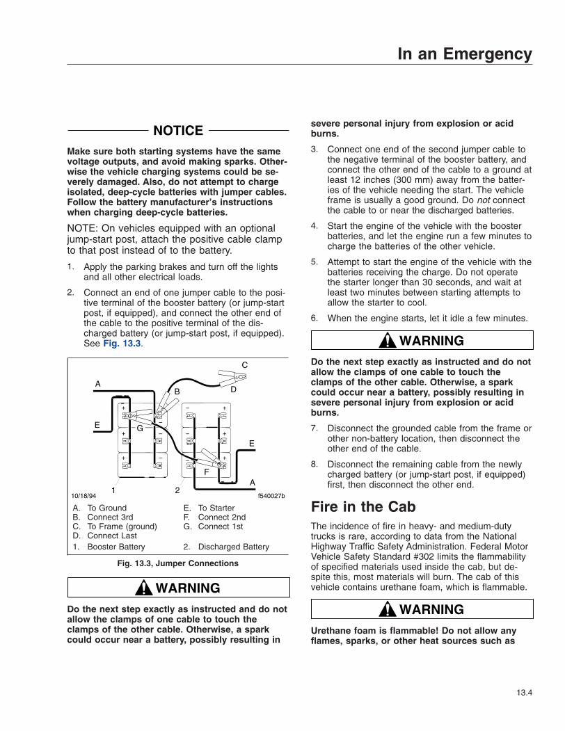
NOTICEMake sure both starting systems have the samevoltage outputs, and avoid making sparks. Other-wise the vehicle charging systems could be se-verely damaged. Also, do not attempt to chargeisolated, deep-cycle batteries with jumper cables.Follow the battery manufacturer’s instructionswhen charging deep-cycle batteries.
NOTE: On vehicles equipped with an optionaljump-start post, attach the positive cable clampto that post instead of to the battery.
1. Apply the parking brakes and turn off the lightsand all other electrical loads.
2. Connect an end of one jumper cable to the posi-tive terminal of the booster battery (or jump-startpost, if equipped), and connect the other end ofthe cable to the positive terminal of the dis-charged battery (or jump-start post, if equipped).See Fig. 13.3.
WARNINGDo the next step exactly as instructed and do notallow the clamps of one cable to touch theclamps of the other cable. Otherwise, a sparkcould occur near a battery, possibly resulting in
severe personal injury from explosion or acidburns.
3. Connect one end of the second jumper cable tothe negative terminal of the booster battery, andconnect the other end of the cable to a ground atleast 12 inches (300 mm) away from the batter-ies of the vehicle needing the start. The vehicleframe is usually a good ground. Do not connectthe cable to or near the discharged batteries.
4. Start the engine of the vehicle with the boosterbatteries, and let the engine run a few minutes tocharge the batteries of the other vehicle.
5. Attempt to start the engine of the vehicle with thebatteries receiving the charge. Do not operatethe starter longer than 30 seconds, and wait atleast two minutes between starting attempts toallow the starter to cool.
6. When the engine starts, let it idle a few minutes.
WARNINGDo the next step exactly as instructed and do notallow the clamps of one cable to touch theclamps of the other cable. Otherwise, a sparkcould occur near a battery, possibly resulting insevere personal injury from explosion or acidburns.
7. Disconnect the grounded cable from the frame orother non-battery location, then disconnect theother end of the cable.
8. Disconnect the remaining cable from the newlycharged battery (or jump-start post, if equipped)first, then disconnect the other end.
Fire in the CabThe incidence of fire in heavy- and medium-dutytrucks is rare, according to data from the NationalHighway Traffic Safety Administration. Federal MotorVehicle Safety Standard #302 limits the flammabilityof specified materials used inside the cab, but de-spite this, most materials will burn. The cab of thisvehicle contains urethane foam, which is flammable.
WARNINGUrethane foam is flammable! Do not allow anyflames, sparks, or other heat sources such as
+
+
+
+
+
+
−
−
−
−
−
−
f540027b10/18/941
AB
C
D
E
F
G
2A
E
A. To GroundB. Connect 3rdC. To Frame (ground)D. Connect Last
E. To StarterF. Connect 2ndG. Connect 1st
1. Booster Battery 2. Discharged Battery
Fig. 13.3, Jumper Connections
In an Emergency
13.4

cigarettes or light bulbs to contact urethanefoam. Urethane foam in contact with such heatsources could cause a serious, rapid fire, whichcould result in death, severe burns, or gas poi-soning, as well as damage to the vehicle.
In Case of a Cab FireAs quickly as possible, bring the vehicle to a safestop, apply the parking brake, turn off the ignition,and get out of the vehicle.
In an Emergency
13.5
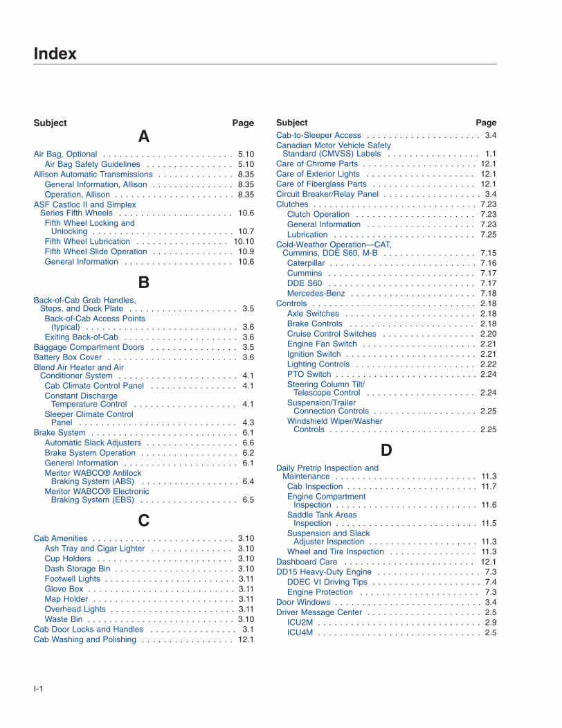
Subject Page
AAir Bag, Optional . . . . . . . . . . . . . . . . . . . . . . . . 5.10
Air Bag Safety Guidelines . . . . . . . . . . . . . . . . 5.10Allison Automatic Transmissions . . . . . . . . . . . . . . 8.35
General Information, Allison . . . . . . . . . . . . . . . 8.35Operation, Allison . . . . . . . . . . . . . . . . . . . . . . 8.35
ASF Castloc II and SimplexSeries Fifth Wheels . . . . . . . . . . . . . . . . . . . . . 10.6Fifth Wheel Locking and
Unlocking . . . . . . . . . . . . . . . . . . . . . . . . . . 10.7Fifth Wheel Lubrication . . . . . . . . . . . . . . . . . 10.10Fifth Wheel Slide Operation . . . . . . . . . . . . . . . 10.9General Information . . . . . . . . . . . . . . . . . . . . 10.6
BBack-of-Cab Grab Handles,
Steps, and Deck Plate . . . . . . . . . . . . . . . . . . . . 3.5Back-of-Cab Access Points
(typical) . . . . . . . . . . . . . . . . . . . . . . . . . . . . 3.6Exiting Back-of-Cab . . . . . . . . . . . . . . . . . . . . . 3.6
Baggage Compartment Doors . . . . . . . . . . . . . . . . 3.5Battery Box Cover . . . . . . . . . . . . . . . . . . . . . . . . 3.6Blend Air Heater and Air
Conditioner System . . . . . . . . . . . . . . . . . . . . . . 4.1Cab Climate Control Panel . . . . . . . . . . . . . . . . 4.1Constant Discharge
Temperature Control . . . . . . . . . . . . . . . . . . . 4.1Sleeper Climate Control
Panel . . . . . . . . . . . . . . . . . . . . . . . . . . . . . 4.3Brake System . . . . . . . . . . . . . . . . . . . . . . . . . . . 6.1
Automatic Slack Adjusters . . . . . . . . . . . . . . . . . 6.6Brake System Operation . . . . . . . . . . . . . . . . . . 6.2General Information . . . . . . . . . . . . . . . . . . . . . 6.1Meritor WABCO® Antilock
Braking System (ABS) . . . . . . . . . . . . . . . . . . 6.4Meritor WABCO® Electronic
Braking System (EBS) . . . . . . . . . . . . . . . . . . 6.5
CCab Amenities . . . . . . . . . . . . . . . . . . . . . . . . . . 3.10
Ash Tray and Cigar Lighter . . . . . . . . . . . . . . . 3.10Cup Holders . . . . . . . . . . . . . . . . . . . . . . . . . 3.10Dash Storage Bin . . . . . . . . . . . . . . . . . . . . . . 3.10Footwell Lights . . . . . . . . . . . . . . . . . . . . . . . . 3.11Glove Box . . . . . . . . . . . . . . . . . . . . . . . . . . . 3.11Map Holder . . . . . . . . . . . . . . . . . . . . . . . . . . 3.11Overhead Lights . . . . . . . . . . . . . . . . . . . . . . . 3.11Waste Bin . . . . . . . . . . . . . . . . . . . . . . . . . . . 3.10
Cab Door Locks and Handles . . . . . . . . . . . . . . . . 3.1Cab Washing and Polishing . . . . . . . . . . . . . . . . . 12.1
Subject PageCab-to-Sleeper Access . . . . . . . . . . . . . . . . . . . . . 3.4Canadian Motor Vehicle Safety
Standard (CMVSS) Labels . . . . . . . . . . . . . . . . . 1.1Care of Chrome Parts . . . . . . . . . . . . . . . . . . . . . 12.1Care of Exterior Lights . . . . . . . . . . . . . . . . . . . . 12.1Care of Fiberglass Parts . . . . . . . . . . . . . . . . . . . 12.1Circuit Breaker/Relay Panel . . . . . . . . . . . . . . . . . . 3.4Clutches . . . . . . . . . . . . . . . . . . . . . . . . . . . . . . 7.23
Clutch Operation . . . . . . . . . . . . . . . . . . . . . . 7.23General Information . . . . . . . . . . . . . . . . . . . . 7.23Lubrication . . . . . . . . . . . . . . . . . . . . . . . . . . 7.25
Cold-Weather Operation—CAT,Cummins, DDE S60, M-B . . . . . . . . . . . . . . . . . 7.15Caterpillar . . . . . . . . . . . . . . . . . . . . . . . . . . . 7.16Cummins . . . . . . . . . . . . . . . . . . . . . . . . . . . 7.17DDE S60 . . . . . . . . . . . . . . . . . . . . . . . . . . . 7.17Mercedes-Benz . . . . . . . . . . . . . . . . . . . . . . . 7.18
Controls . . . . . . . . . . . . . . . . . . . . . . . . . . . . . . 2.18Axle Switches . . . . . . . . . . . . . . . . . . . . . . . . 2.18Brake Controls . . . . . . . . . . . . . . . . . . . . . . . 2.18Cruise Control Switches . . . . . . . . . . . . . . . . . 2.20Engine Fan Switch . . . . . . . . . . . . . . . . . . . . . 2.21Ignition Switch . . . . . . . . . . . . . . . . . . . . . . . . 2.21Lighting Controls . . . . . . . . . . . . . . . . . . . . . . 2.22PTO Switch . . . . . . . . . . . . . . . . . . . . . . . . . . 2.24Steering Column Tilt/
Telescope Control . . . . . . . . . . . . . . . . . . . . 2.24Suspension/Trailer
Connection Controls . . . . . . . . . . . . . . . . . . . 2.25Windshield Wiper/Washer
Controls . . . . . . . . . . . . . . . . . . . . . . . . . . . 2.25
DDaily Pretrip Inspection and
Maintenance . . . . . . . . . . . . . . . . . . . . . . . . . . 11.3Cab Inspection . . . . . . . . . . . . . . . . . . . . . . . . 11.7Engine Compartment
Inspection . . . . . . . . . . . . . . . . . . . . . . . . . . 11.6Saddle Tank Areas
Inspection . . . . . . . . . . . . . . . . . . . . . . . . . . 11.5Suspension and Slack
Adjuster Inspection . . . . . . . . . . . . . . . . . . . . 11.3Wheel and Tire Inspection . . . . . . . . . . . . . . . . 11.3
Dashboard Care . . . . . . . . . . . . . . . . . . . . . . . . 12.1DD15 Heavy-Duty Engine . . . . . . . . . . . . . . . . . . . 7.3
DDEC VI Driving Tips . . . . . . . . . . . . . . . . . . . . 7.4Engine Protection . . . . . . . . . . . . . . . . . . . . . . 7.3
Door Windows . . . . . . . . . . . . . . . . . . . . . . . . . . . 3.4Driver Message Center . . . . . . . . . . . . . . . . . . . . . 2.5
ICU2M . . . . . . . . . . . . . . . . . . . . . . . . . . . . . . 2.9ICU4M . . . . . . . . . . . . . . . . . . . . . . . . . . . . . . 2.5
Index
I-1
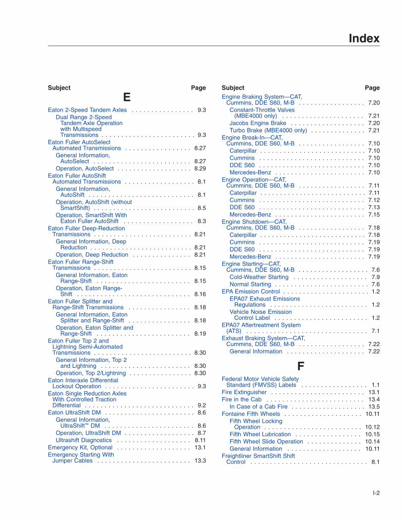
Subject Page
EEaton 2-Speed Tandem Axles . . . . . . . . . . . . . . . . 9.3
Dual Range 2-SpeedTandem Axle Operationwith MultispeedTransmissions . . . . . . . . . . . . . . . . . . . . . . . . 9.3
Eaton Fuller AutoSelectAutomated Transmissions . . . . . . . . . . . . . . . . . 8.27General Information,
AutoSelect . . . . . . . . . . . . . . . . . . . . . . . . . 8.27Operation, AutoSelect . . . . . . . . . . . . . . . . . . . 8.29
Eaton Fuller AutoShiftAutomated Transmissions . . . . . . . . . . . . . . . . . . 8.1General Information,
AutoShift . . . . . . . . . . . . . . . . . . . . . . . . . . . 8.1Operation, AutoShift (without
SmartShift) . . . . . . . . . . . . . . . . . . . . . . . . . . 8.5Operation, SmartShift With
Eaton Fuller AutoShift . . . . . . . . . . . . . . . . . . 8.3Eaton Fuller Deep-Reduction
Transmissions . . . . . . . . . . . . . . . . . . . . . . . . . 8.21General Information, Deep
Reduction . . . . . . . . . . . . . . . . . . . . . . . . . . 8.21Operation, Deep Reduction . . . . . . . . . . . . . . . 8.21
Eaton Fuller Range-ShiftTransmissions . . . . . . . . . . . . . . . . . . . . . . . . . 8.15General Information, Eaton
Range-Shift . . . . . . . . . . . . . . . . . . . . . . . . 8.15Operation, Eaton Range-
Shift . . . . . . . . . . . . . . . . . . . . . . . . . . . . . 8.16Eaton Fuller Splitter and
Range-Shift Transmissions . . . . . . . . . . . . . . . . 8.18General Information, Eaton
Splitter and Range-Shift . . . . . . . . . . . . . . . . 8.18Operation, Eaton Splitter and
Range-Shift . . . . . . . . . . . . . . . . . . . . . . . . 8.19Eaton Fuller Top 2 and
Lightning Semi-AutomatedTransmissions . . . . . . . . . . . . . . . . . . . . . . . . . 8.30General Information, Top 2
and Lightning . . . . . . . . . . . . . . . . . . . . . . . 8.30Operation, Top 2/Lightning . . . . . . . . . . . . . . . . 8.30
Eaton Interaxle DifferentialLockout Operation . . . . . . . . . . . . . . . . . . . . . . . 9.3
Eaton Single Reduction AxlesWith Controlled TractionDifferential . . . . . . . . . . . . . . . . . . . . . . . . . . . . 9.2
Eaton UltraShift DM . . . . . . . . . . . . . . . . . . . . . . . 8.6General Information,
UltraShift™ DM . . . . . . . . . . . . . . . . . . . . . . . 8.6Operation, UltraShift DM . . . . . . . . . . . . . . . . . . 8.7Ultrashift Diagnostics . . . . . . . . . . . . . . . . . . . 8.11
Emergency Kit, Optional . . . . . . . . . . . . . . . . . . . 13.1Emergency Starting With
Jumper Cables . . . . . . . . . . . . . . . . . . . . . . . . 13.3
Subject PageEngine Braking System—CAT,
Cummins, DDE S60, M-B . . . . . . . . . . . . . . . . . 7.20Constant-Throttle Valves
(MBE4000 only) . . . . . . . . . . . . . . . . . . . . . 7.21Jacobs Engine Brake . . . . . . . . . . . . . . . . . . . 7.20Turbo Brake (MBE4000 only) . . . . . . . . . . . . . . 7.21
Engine Break-In—CAT,Cummins, DDE S60, M-B . . . . . . . . . . . . . . . . . 7.10Caterpillar . . . . . . . . . . . . . . . . . . . . . . . . . . . 7.10Cummins . . . . . . . . . . . . . . . . . . . . . . . . . . . 7.10DDE S60 . . . . . . . . . . . . . . . . . . . . . . . . . . . 7.10Mercedes-Benz . . . . . . . . . . . . . . . . . . . . . . . 7.10
Engine Operation—CAT,Cummins, DDE S60, M-B . . . . . . . . . . . . . . . . . 7.11Caterpillar . . . . . . . . . . . . . . . . . . . . . . . . . . . 7.11Cummins . . . . . . . . . . . . . . . . . . . . . . . . . . . 7.12DDE S60 . . . . . . . . . . . . . . . . . . . . . . . . . . . 7.13Mercedes-Benz . . . . . . . . . . . . . . . . . . . . . . . 7.15
Engine Shutdown—CAT,Cummins, DDE S60, M-B . . . . . . . . . . . . . . . . . 7.18Caterpillar . . . . . . . . . . . . . . . . . . . . . . . . . . . 7.18Cummins . . . . . . . . . . . . . . . . . . . . . . . . . . . 7.19DDE S60 . . . . . . . . . . . . . . . . . . . . . . . . . . . 7.19Mercedes-Benz . . . . . . . . . . . . . . . . . . . . . . . 7.19
Engine Starting—CAT,Cummins, DDE S60, M-B . . . . . . . . . . . . . . . . . . 7.6Cold-Weather Starting . . . . . . . . . . . . . . . . . . . 7.9Normal Starting . . . . . . . . . . . . . . . . . . . . . . . . 7.6
EPA Emission Control . . . . . . . . . . . . . . . . . . . . . . 1.2EPA07 Exhaust Emissions
Regulations . . . . . . . . . . . . . . . . . . . . . . . . . 1.2Vehicle Noise Emission
Control Label . . . . . . . . . . . . . . . . . . . . . . . . 1.2EPA07 Aftertreatment System
(ATS) . . . . . . . . . . . . . . . . . . . . . . . . . . . . . . . 7.1Exhaust Braking System—CAT,
Cummins, DDE S60, M-B . . . . . . . . . . . . . . . . . 7.22General Information . . . . . . . . . . . . . . . . . . . . 7.22
FFederal Motor Vehicle Safety
Standard (FMVSS) Labels . . . . . . . . . . . . . . . . . 1.1Fire Extinguisher . . . . . . . . . . . . . . . . . . . . . . . . 13.1Fire in the Cab . . . . . . . . . . . . . . . . . . . . . . . . . 13.4
In Case of a Cab Fire . . . . . . . . . . . . . . . . . . . 13.5Fontaine Fifth Wheels . . . . . . . . . . . . . . . . . . . . 10.11
Fifth Wheel LockingOperation . . . . . . . . . . . . . . . . . . . . . . . . . 10.12
Fifth Wheel Lubrication . . . . . . . . . . . . . . . . . 10.15Fifth Wheel Slide Operation . . . . . . . . . . . . . . 10.14General Information . . . . . . . . . . . . . . . . . . . 10.11
Freightliner SmartShift ShiftControl . . . . . . . . . . . . . . . . . . . . . . . . . . . . . . 8.1
Index
I-2

Subject Page
General Information,SmartShift™ . . . . . . . . . . . . . . . . . . . . . . . . . 8.1
GGrab Handles and Access
Steps . . . . . . . . . . . . . . . . . . . . . . . . . . . . . . . 3.1Entering the Driver’s Side for
Right-Hand-Drive Vehicles . . . . . . . . . . . . . . . 3.3Entering the Driver’s Side . . . . . . . . . . . . . . . . . 3.2Entering the Passenger’s
Side for Right-Hand-DriveVehicles . . . . . . . . . . . . . . . . . . . . . . . . . . . . 3.4
Entering the Passenger’sSide . . . . . . . . . . . . . . . . . . . . . . . . . . . . . . 3.2
Exiting the Driver’s Side forRight-Hand-Drive Vehicles . . . . . . . . . . . . . . . 3.3
Exiting the Driver’s Side . . . . . . . . . . . . . . . . . . 3.2Exiting the Passenger’s Side
for Right-Hand-DriveVehicles . . . . . . . . . . . . . . . . . . . . . . . . . . . . 3.4
Exiting the Passenger’s Side . . . . . . . . . . . . . . 3.3
HHazard Warning Lights . . . . . . . . . . . . . . . . . . . . 13.1High-Altitude Operation—CAT,
Cummins, DDE S60, M-B . . . . . . . . . . . . . . . . . 7.18Holland Fifth Wheels . . . . . . . . . . . . . . . . . . . . . 10.1
Fifth Wheel LockingOperation . . . . . . . . . . . . . . . . . . . . . . . . . . 10.2
Fifth Wheel Lubrication . . . . . . . . . . . . . . . . . . 10.6Fifth Wheel Slide Operation . . . . . . . . . . . . . . . 10.4General Information . . . . . . . . . . . . . . . . . . . . 10.1
Holland Trailer Coupling . . . . . . . . . . . . . . . . . . 10.17General Information . . . . . . . . . . . . . . . . . . . 10.17Operation . . . . . . . . . . . . . . . . . . . . . . . . . . 10.17
Hood Tilting . . . . . . . . . . . . . . . . . . . . . . . . . . . . 3.6To Return the Hood . . . . . . . . . . . . . . . . . . . . . 3.7To Tilt the Hood . . . . . . . . . . . . . . . . . . . . . . . . 3.6
IIgnition and Lock Key . . . . . . . . . . . . . . . . . . . . . . 3.1Instrumentation Control Units . . . . . . . . . . . . . . . . . 2.1
Ignition Sequence . . . . . . . . . . . . . . . . . . . . . . 2.1Instruments . . . . . . . . . . . . . . . . . . . . . . . . . . . . 2.14
Air Intake Restriction Gauge . . . . . . . . . . . . . . 2.14Ammeter . . . . . . . . . . . . . . . . . . . . . . . . . . . 2.16Application Air Pressure
Gauge . . . . . . . . . . . . . . . . . . . . . . . . . . . . 2.16Coolant Temperature Gauge . . . . . . . . . . . . . . 2.16Drive Axle Oil Temperature
Gauges . . . . . . . . . . . . . . . . . . . . . . . . . . . 2.16
Subject Page
Engine Oil Pressure Gauge . . . . . . . . . . . . . . . 2.16Engine Oil Temperature
Gauge . . . . . . . . . . . . . . . . . . . . . . . . . . . . 2.17Fuel Gauge . . . . . . . . . . . . . . . . . . . . . . . . . . 2.17Primary and Secondary Air
Pressure Gauges . . . . . . . . . . . . . . . . . . . . . 2.17Pyrometer . . . . . . . . . . . . . . . . . . . . . . . . . . . 2.17Speedometer . . . . . . . . . . . . . . . . . . . . . . . . 2.17Tachometer . . . . . . . . . . . . . . . . . . . . . . . . . . 2.17Transmission Fluid
Temperature Gauge . . . . . . . . . . . . . . . . . . . 2.18Turbocharger Boost
Pressure Gauge . . . . . . . . . . . . . . . . . . . . . 2.18Voltmeter . . . . . . . . . . . . . . . . . . . . . . . . . . . 2.18
KKeyless Security System,
Optional . . . . . . . . . . . . . . . . . . . . . . . . . . . . . . 3.7Fob Battery Replacement . . . . . . . . . . . . . . . . . 3.9Fob Programming . . . . . . . . . . . . . . . . . . . . . . 3.9General Information . . . . . . . . . . . . . . . . . . . . . 3.7How It Works . . . . . . . . . . . . . . . . . . . . . . . . . 3.8
LLane Departure Warning
Controls . . . . . . . . . . . . . . . . . . . . . . . . . . . . . 2.38
MMeritor Drive Axles With Main
Differential Lock . . . . . . . . . . . . . . . . . . . . . . . . 9.1Meritor Engine Synchro Shift
(ESS) Automated Models . . . . . . . . . . . . . . . . . 8.32General Information, ESS . . . . . . . . . . . . . . . . 8.32Operation, ESS . . . . . . . . . . . . . . . . . . . . . . . 8.33
Meritor Interaxle DifferentialLockout Operation . . . . . . . . . . . . . . . . . . . . . . . 9.2
Meritor Main Differential LockOperation . . . . . . . . . . . . . . . . . . . . . . . . . . . . . 9.1
Meritor Range-ShiftTransmissions . . . . . . . . . . . . . . . . . . . . . . . . . 8.24General Information, Meritor
Range-Shift . . . . . . . . . . . . . . . . . . . . . . . . 8.24Operation, Meritor Range-
Shift . . . . . . . . . . . . . . . . . . . . . . . . . . . . . 8.24Meritor Single Drive Axles With
Traction Equalizer . . . . . . . . . . . . . . . . . . . . . . . 9.1Meritor Splitter and Range-Shift
Transmissions . . . . . . . . . . . . . . . . . . . . . . . . . 8.26General Information, Meritor
Splitter and Range-Shift . . . . . . . . . . . . . . . . 8.26Operation, Meritor Splitter
and Range-Shift . . . . . . . . . . . . . . . . . . . . . 8.26
Index
I-3
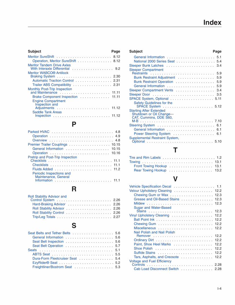
Subject PageMeritor SureShift . . . . . . . . . . . . . . . . . . . . . . . . 8.12
Operation, Meritor SureShift . . . . . . . . . . . . . . . 8.12Meritor Tandem Drive Axles
With Interaxle Differential . . . . . . . . . . . . . . . . . . 9.2Meritor WABCO® Antilock
Braking System . . . . . . . . . . . . . . . . . . . . . . . . 2.30Automatic Traction Control . . . . . . . . . . . . . . . . 2.31Trailer ABS Compatibility . . . . . . . . . . . . . . . . . 2.31
Monthly Post-Trip Inspectionand Maintenance . . . . . . . . . . . . . . . . . . . . . . 11.11Brake Component Inspection . . . . . . . . . . . . . 11.11Engine Compartment
Inspection andAdjustments . . . . . . . . . . . . . . . . . . . . . . . 11.12
Saddle Tank AreasInspection . . . . . . . . . . . . . . . . . . . . . . . . . 11.12
PParked HVAC . . . . . . . . . . . . . . . . . . . . . . . . . . . 4.8
Operation . . . . . . . . . . . . . . . . . . . . . . . . . . . . 4.9Overview . . . . . . . . . . . . . . . . . . . . . . . . . . . . 4.8
Premier Trailer Couplings . . . . . . . . . . . . . . . . . . 10.15General Information . . . . . . . . . . . . . . . . . . . 10.15Operation . . . . . . . . . . . . . . . . . . . . . . . . . . 10.16
Pretrip and Post-Trip InspectionChecklists . . . . . . . . . . . . . . . . . . . . . . . . . . . . 11.1Checklists . . . . . . . . . . . . . . . . . . . . . . . . . . . 11.1Fluids Added . . . . . . . . . . . . . . . . . . . . . . . . . 11.2Periodic Inspections and
Maintenance, GeneralInformation . . . . . . . . . . . . . . . . . . . . . . . . . 11.1
RRoll Stability Advisor and
Control System . . . . . . . . . . . . . . . . . . . . . . . . 2.26Hard-Braking Advisor . . . . . . . . . . . . . . . . . . . 2.26Roll Stability Advisor . . . . . . . . . . . . . . . . . . . . 2.26Roll Stability Control . . . . . . . . . . . . . . . . . . . . 2.26Trip/Leg Totals . . . . . . . . . . . . . . . . . . . . . . . . 2.27
SSeat Belts and Tether Belts . . . . . . . . . . . . . . . . . . 5.6
General Information . . . . . . . . . . . . . . . . . . . . . 5.6Seat Belt Inspection . . . . . . . . . . . . . . . . . . . . . 5.6Seat Belt Operation . . . . . . . . . . . . . . . . . . . . . 5.7
Seats . . . . . . . . . . . . . . . . . . . . . . . . . . . . . . . . 5.1ABTS Seat . . . . . . . . . . . . . . . . . . . . . . . . . . . 5.5Dura-Form Fleetcruiser Seat . . . . . . . . . . . . . . . 5.4EzyRider® Seat . . . . . . . . . . . . . . . . . . . . . . . . 5.2Freightliner/Bostrom Seat . . . . . . . . . . . . . . . . . 5.3
Subject Page
General Information . . . . . . . . . . . . . . . . . . . . . 5.1National 2000 Series Seat . . . . . . . . . . . . . . . . . 5.4
Sleeper Bunk Latches . . . . . . . . . . . . . . . . . . . . . 3.4Sleeper Compartment
Restraints . . . . . . . . . . . . . . . . . . . . . . . . . . . . 5.9Bunk Restraint Adjustment . . . . . . . . . . . . . . . . 5.9Bunk Restraint Operation . . . . . . . . . . . . . . . . . 5.9General Information . . . . . . . . . . . . . . . . . . . . . 5.9
Sleeper Compartment Vents . . . . . . . . . . . . . . . . . 3.4Sleeper Door . . . . . . . . . . . . . . . . . . . . . . . . . . . 3.5SPACE System, Optional . . . . . . . . . . . . . . . . . . . 5.11
Safety Guidelines for theSPACE System . . . . . . . . . . . . . . . . . . . . . . 5.12
Starting After ExtendedShutdown or Oil Change—CAT, Cummins, DDE S60,M-B . . . . . . . . . . . . . . . . . . . . . . . . . . . . . . . . 7.10
Steering System . . . . . . . . . . . . . . . . . . . . . . . . . 6.1General Information . . . . . . . . . . . . . . . . . . . . . 6.1Power Steering System . . . . . . . . . . . . . . . . . . 6.1
Supplemental Restraint System,Optional . . . . . . . . . . . . . . . . . . . . . . . . . . . . . 5.10
TTire and Rim Labels . . . . . . . . . . . . . . . . . . . . . . . 1.2Towing . . . . . . . . . . . . . . . . . . . . . . . . . . . . . . . 13.1
Front Towing Hookup . . . . . . . . . . . . . . . . . . . 13.1Rear Towing Hookup . . . . . . . . . . . . . . . . . . . 13.2
VVehicle Specification Decal . . . . . . . . . . . . . . . . . . 1.1Velour Upholstery Cleaning . . . . . . . . . . . . . . . . . 12.2
Chewing Gum or Wax . . . . . . . . . . . . . . . . . . . 12.3Grease and Oil-Based Stains . . . . . . . . . . . . . . 12.3Mildew . . . . . . . . . . . . . . . . . . . . . . . . . . . . . 12.3Sugar and Water-Based
Stains . . . . . . . . . . . . . . . . . . . . . . . . . . . . 12.3Vinyl Upholstery Cleaning . . . . . . . . . . . . . . . . . . 12.2
Ball Point Ink . . . . . . . . . . . . . . . . . . . . . . . . . 12.2Chewing Gum . . . . . . . . . . . . . . . . . . . . . . . . 12.2Miscellaneous . . . . . . . . . . . . . . . . . . . . . . . . 12.2Nail Polish and Nail Polish
Remover . . . . . . . . . . . . . . . . . . . . . . . . . . 12.2Ordinary Dirt . . . . . . . . . . . . . . . . . . . . . . . . . 12.2Paint, Shoe Heel Marks . . . . . . . . . . . . . . . . . 12.2Shoe Polish . . . . . . . . . . . . . . . . . . . . . . . . . 12.2Sulfide Stains . . . . . . . . . . . . . . . . . . . . . . . . 12.2Tars, Asphalts, and Creosote . . . . . . . . . . . . . . 12.2
Voltage and Fuel EfficiencyControls . . . . . . . . . . . . . . . . . . . . . . . . . . . . . 2.28Cab Load Disconnect Switch . . . . . . . . . . . . . . 2.28
Index
I-4

Subject Page
Idle Shutdown Timer . . . . . . . . . . . . . . . . . . . . 2.28Low Voltage Disconnect
Feature . . . . . . . . . . . . . . . . . . . . . . . . . . . 2.28Optimized Idle® . . . . . . . . . . . . . . . . . . . . . . . 2.28
VORAD VS-400 System . . . . . . . . . . . . . . . . . . . 2.32Collision Warning System . . . . . . . . . . . . . . . . 2.35Driver Interface Unit . . . . . . . . . . . . . . . . . . . . 2.32Failure Display Mode/Fault
Codes . . . . . . . . . . . . . . . . . . . . . . . . . . . . 2.37Maintenance . . . . . . . . . . . . . . . . . . . . . . . . . 2.37Side Object Detection . . . . . . . . . . . . . . . . . . . 2.36SmartCruise . . . . . . . . . . . . . . . . . . . . . . . . . 2.36Special Road Situations . . . . . . . . . . . . . . . . . 2.36
WWarning and Indicator Lights . . . . . . . . . . . . . . . . . 2.2
Engine Protection System . . . . . . . . . . . . . . . . . 2.2Water-Valve-Controlled Heater
and Air Conditioner System . . . . . . . . . . . . . . . . . 4.4Air Conditioning, Sleeper
Heater and Air Conditioner . . . . . . . . . . . . . . . 4.8Air Conditioning . . . . . . . . . . . . . . . . . . . . . . . . 4.6Defogging and Defrosting
Using Fresh Air . . . . . . . . . . . . . . . . . . . . . . . 4.6Fresh Air . . . . . . . . . . . . . . . . . . . . . . . . . . . . 4.7General Information . . . . . . . . . . . . . . . . . . . . . 4.4Heating, Sleeper Heater and
Air Conditioner . . . . . . . . . . . . . . . . . . . . . . . 4.7Heating . . . . . . . . . . . . . . . . . . . . . . . . . . . . . 4.6
Weekly Post-Trip Inspectionand Maintenance . . . . . . . . . . . . . . . . . . . . . . . 11.9Engine Compartment
Inspection . . . . . . . . . . . . . . . . . . . . . . . . . . 11.9Windshield Washer Reservoir . . . . . . . . . . . . . . . . 3.11
ZZF Meritor FreedomLine
Automated Transmissions . . . . . . . . . . . . . . . . . 8.13General Information,
FreedomLine . . . . . . . . . . . . . . . . . . . . . . . 8.13Operation, FreedomLine . . . . . . . . . . . . . . . . . 8.13
Index
I-5