Embed Size (px)
Citation preview

Copyright © 2011 Casa Software Ltd. www.casaxps.com
1
Centre of Mass A central theme in mathematical modelling is that of reducing complex problems to simpler, and
hopefully, equivalent problems for which mathematical analysis is possible. The concept of centre-
of-mass is one such mathematical device for reducing the complexity of a problem to a more
tractable system for which an understanding can be attempted in terms of mathematics.
The question of why loading a set of shelves from the top is more likely to induce an accident than if
loaded first from the bottom is one such problem addressed by reducing the shelves and boxes to a
single mass at a location through which the stability of the shelves can be understood.
The centre-of-mass for a rigid body is central to almost all the solutions so far seen in this text. Each
time a ladder is represented by a uniform rod, or a cricket ball is modelled as a particle, the essential
idea behind centre-of-mass is deployed, namely, there exists a point in space through which the
weight of these bodies acts. The physical dimensions are then only important in terms of the turning
effect resulting from the rigid nature of the bodies.
While the centre of mass can be determined for 3D objects, the subject will be developed only for
1D and 2D rigid bodies. A 2D rigid body is referred to in mechanics as a lamina, which is
characterised by a body with some mass and having an appreciable plane area, but negligible
thickness. Discussions will be further limited to uniform lamina and networks of uniform rods.
The significance of the term uniform is the centre of mass for a uniform rigid body can be
determined based on the geometric lines of symmetry. Since the centre of mass for a uniform
lamina must lie on a line of geometric symmetry, two or more geometric lines of symmetry cross at
the position for the centre of mass. Thus, a uniform lamina with the geometry of a circle will have
the centre of mass coinciding with the geometric centre for the circular shape.
Provided a complex lamina can be broken down into a set of shapes for which the centre of mass is
known, the centre of mass for complex shaped lamina can be determined from the techniques
described below.

Copyright © 2011 Casa Software Ltd. www.casaxps.com
2
Calculating the centre of mass is performed by replacing the uniform lamina by a light lamina for
which a single particle of mass equal to the mass of the uniform lamina is attached to the light
lamina such that the turning effect under the influence of gravity for the two laminas about any line
within the plane of these laminas is the same.
For a square uniform lamina lying in the horizontal plane, the turning effect of the lamina would be
the same as that of a particle positioned at the point where two axes of symmetry cross, with the
same mass as the uniform lamina.
When discussing turning effects in 2D, the significant statement is the turning effect is now about a
line rather than a point. For 1D problems, where an object is modelled using a rigid rod, the turning
effect was considered to be about a point. Another way of thinking about the 1D concept of rotation
about a point is that the point is the cross-section of a line perpendicular to the rod and the plane of
the paper on which the rod is drawn. In this sense moments, even for 1D problems, were always
about a line, not a point.
For more complicated shaped laminas, the problem of determining the centre of mass is that of
reducing the lamina to shapes for which centre of masses are known, and then determining the
centre of mass for a set of particles with masses and positions determined by these simpler shapes.
For example, a square lamina with a quadrant missing could be broken down into a rectangle and a
square. The centre of mass for the rectangle and square are determined by geometric symmetry,
and these component lamina replaced by particles of equivalent masses.
The centre of mass for the original shape is then determined from the centre of mass for a set of
particles of different masses attached to a light lamina.
2M
1M
3M
Uniform lamina mass M Light lamina with particle mass M at centre-of-
mass for the uniform lamina

Copyright © 2011 Casa Software Ltd. www.casaxps.com
3
The light lamina to which these particles are attached is only conceptual and can be viewed as any
shape we wish, which is important for situations where the centre of mass lies outside the boundary
of the original lamina. The centre of mass for a hollow object, such as a washer, is not within the
material part of the washer.
If a mechanical system can be reduced to a set of particles of known mass and spatial separation,
then the centre of mass for the original rigid body can be calculated by summing the moments for
each particle about any line we choose, and then calculating the distance from the line for a particle
equal in mass to the total mass such that the moment of the particle of total mass is the same as the
sum of the moments for all the particles. The sum of moments must account for a specified
rotational sense with respect to the chosen line.
Moments about the x-axis for component particles:
Must be equivalent to the moment for the total mass
particle
where is the distance of the centre of mass from the x-
axis.
Therefore,
For the component particles, moments about the y-axis:
Must be equivalent to the moment for the total mass particle:
where is the distance of the centre of mass from the y-axis.
Therefore,
Copyright © 2011 Casa Software Ltd. www.casaxps.com
4
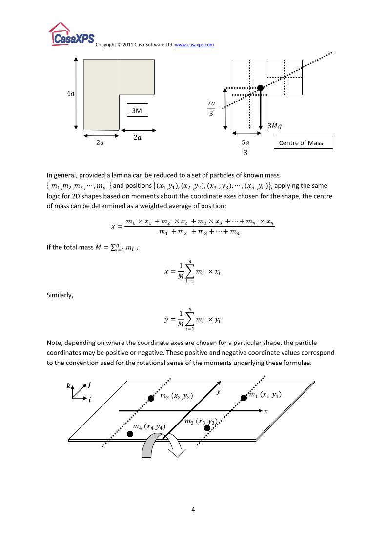
In general, provided a lamina can be reduced to a set of particles of known mass
and positions , applying the same
logic for 2D shapes based on moments about the coordinate axes chosen for the shape, the centre
of mass can be determined as a weighted average of position:
If the total mass ,
Similarly,
Note, depending on where the coordinate axes are chosen for a particular shape, the particle
coordinates may be positive or negative. These positive and negative coordinate values correspond
to the convention used for the rotational sense of the moments underlying these formulae.
3M
Centre of Mass
Copyright © 2011 Casa Software Ltd. www.casaxps.com
5
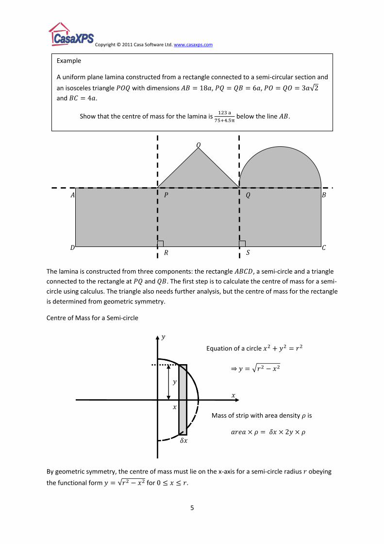
The lamina is constructed from three components: the rectangle , a semi-circle and a triangle
connected to the rectangle at and . The first step is to calculate the centre of mass for a semi-
circle using calculus. The triangle also needs further analysis, but the centre of mass for the rectangle
is determined from geometric symmetry.
Centre of Mass for a Semi-circle
By geometric symmetry, the centre of mass must lie on the x-axis for a semi-circle radius obeying
the functional form for .
Equation of a circle
Mass of strip with area density is
Example
A uniform plane lamina constructed from a rectangle connected to a semi-circular section and
an isosceles triangle with dimensions , ,
and .
Show that the centre of mass for the lamina is below the line .

Copyright © 2011 Casa Software Ltd. www.casaxps.com
6
Calculating distance for the centre of mass from the y-axis for a semi-circle of uniform density per
unit area is performed using the concepts of summing moments in exactly the same way moments
are calculated for sets of particles. The semi-circle is approximated by a set of rectangular regions of
width and height .
By symmetry, the centre of mass for these rectangles lies on the x-axis and the mass for each
rectangle positioned from the y-axis is
Where .
The total mass for the semi-circle is known exactly, and is acting through the centre of
mass for the semi-circle at the, yet to be determined, position from the y-axis.
If the centre of mass for the semi-circle is from the y-axis, then an approximation to the centre of
mass will be
In the digital age, such an expression would be sufficient to obtain an answer within the precision
achieved by a calculator or a computer, however, calculus can be used to derive an exact expression
for the centre of mass.
If the number of rectangles used in this approximation is allowed to increase, the width for each
rectangle decreases, thus as rectangles are added to the approximation, the area and therefore the
mass for each rectangle gets smaller. By increasing the number of rectangles, the number of small
masses becomes ever larger, and understanding the consequences of adding more and more of ever
Copyright © 2011 Casa Software Ltd. www.casaxps.com
7
smaller items is precisely the stuff of calculus. Mechanics, differentiation and integration are
strongly linked.
To obtain the centre of mass for the semi-circle, as the summation tends to the integral (the
sum involved in must go to zero as )
Using the substitution , with limits from to .
This result is a standard result from a host of other standard centres of mass for uniform laminas, all
of which will be provided under examination conditions, but nevertheless, illustrates where a desire
to understand a physical object leads to the concepts of calculus and therefore should be seen as the
motivation for studying techniques of integration in other mathematics courses.
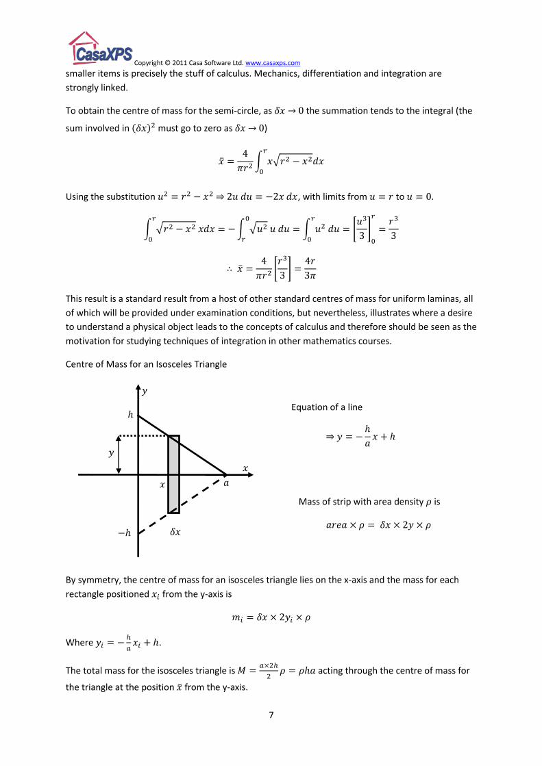
Centre of Mass for an Isosceles Triangle
By symmetry, the centre of mass for an isosceles triangle lies on the x-axis and the mass for each
rectangle positioned from the y-axis is
Where .
The total mass for the isosceles triangle is acting through the centre of mass for
the triangle at the position from the y-axis.
Equation of a line
Mass of strip with area density is
Copyright © 2011 Casa Software Ltd. www.casaxps.com
8
If the centre of mass for the triangle is from the y-axis, then an approximation to the centre of
mass will be
Again moving to the limit as
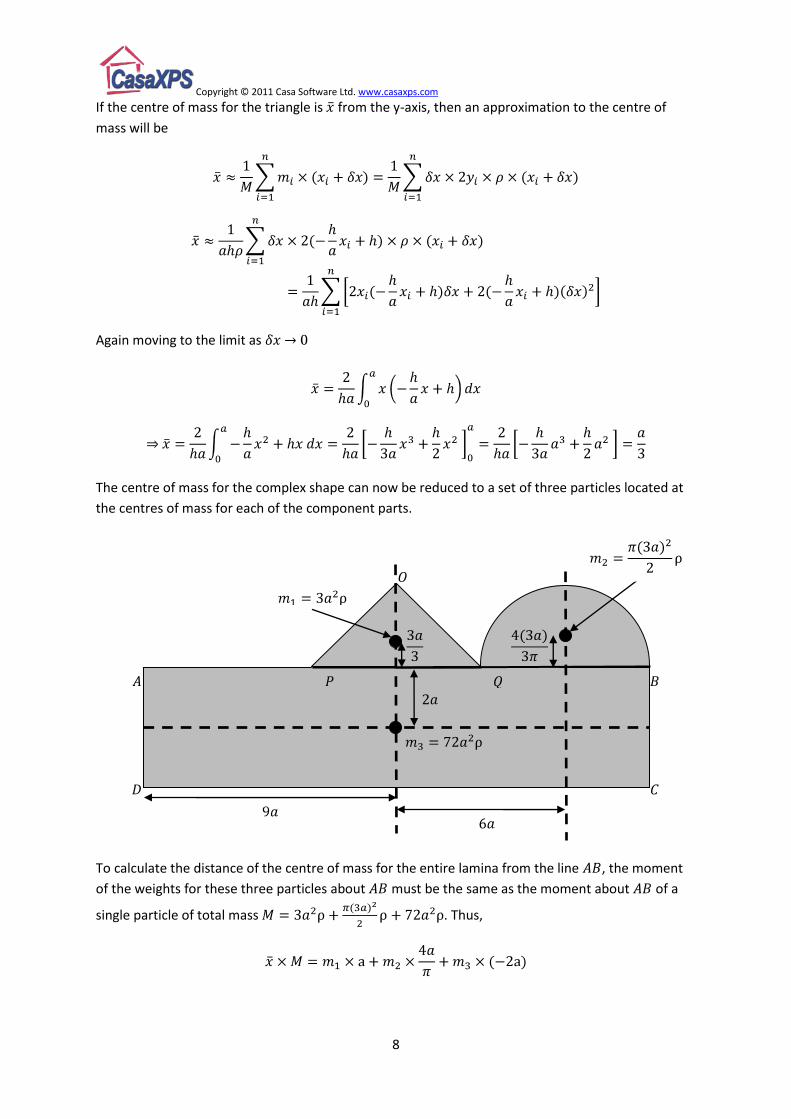
The centre of mass for the complex shape can now be reduced to a set of three particles located at
the centres of mass for each of the component parts.
To calculate the distance of the centre of mass for the entire lamina from the line , the moment
of the weights for these three particles about must be the same as the moment about of a
single particle of total mass . Thus,
Copyright © 2011 Casa Software Ltd. www.casaxps.com
9
Since the centre of mass for the particle corresponding to the rectangle is on the opposite side of the
line to the two particles corresponding to the triangle and the semi-circle, the moment for the
rectangle is negative relative to the two particles above the line .
The value for is negative, therefore the centre of mass is below the line .
The problem differs slightly from the previous example by virtue of a missing square of metal rather
than shapes being added to a square. The problem could be approached by dividing the metal
bracket into many smaller rectangles from which the centre of mass for the bracket could be
calculated. However, by applying mathematical reasoning, the problem can be solved by considering
three masses corresponding to:
1. The mass of a square bracket without the removal of the smaller square.
2. The mass of the square corresponding to the missing smaller square.
3. The mass of the bracket with the smaller square removed.
The reasoning is as follows. The bracket before the smaller square is punched out consists of the
union of the bracket after the smaller square is removed and the small square itself. If the metal
plate from which the bracket is made is considered to be constructed from the bracket plus the
smaller square, the centre of mass for the square metal plate can be expressed in terms of the two
component parts. The only difference is the unknown is now one of the component parts.
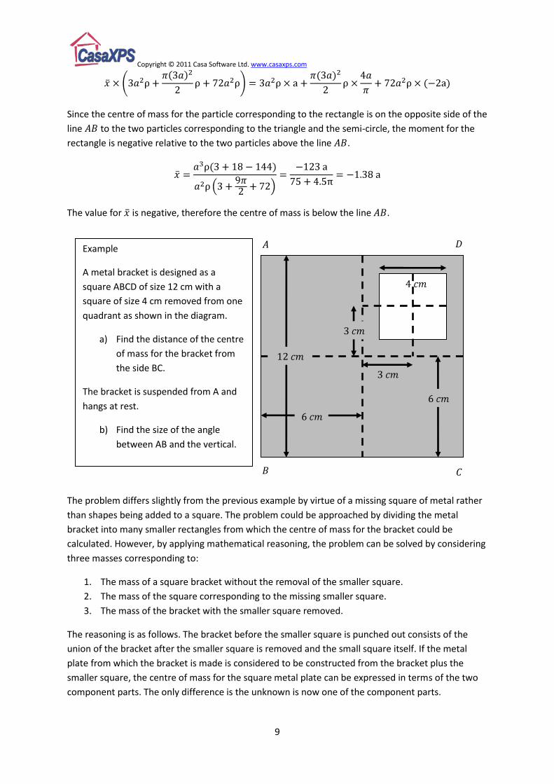
Example
A metal bracket is designed as a
square ABCD of size 12 cm with a
square of size 4 cm removed from one
quadrant as shown in the diagram.
a) Find the distance of the centre
of mass for the bracket from
the side BC.
The bracket is suspended from A and
hangs at rest.
b) Find the size of the angle
between AB and the vertical.
Copyright © 2011 Casa Software Ltd. www.casaxps.com
10
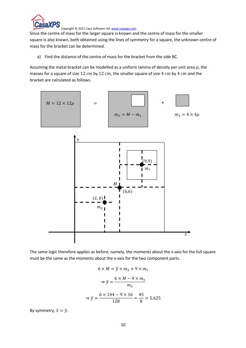
Since the centre of mass for the larger square is known and the centre of mass for the smaller
square is also known, both obtained using the lines of symmetry for a square, the unknown centre of
mass for the bracket can be determined.
a) Find the distance of the centre of mass for the bracket from the side BC.
Assuming the metal bracket can be modelled as a uniform lamina of density per unit area , the
masses for a square of size by , the smaller square of size by and the
bracket are calculated as follows.
The same logic therefore applies as before, namely, the moments about the x-axis for the full square
must be the same as the moments about the x-axis for the two component parts.
By symmetry, .

Copyright © 2011 Casa Software Ltd. www.casaxps.com
11
b) Find the size of the angle between AB and the vertical.
The lamina is suspended from the corner and is assumed to be at rest. The practical method for
determining the centre of mass for a metal bracket is to suspend the bracket from two different
corners and each time mark the line on the bracket through the corner from which the bracket is
suspended and a plumb line hanging vertically downwards. Two such lines marked on the metal
bracket would intersect at the centre of mass.
If the bracket is suspended at rest from the corner , then the mathematical solution is therefore
obtained by drawing a line through which passes through the centre of mass previously calculated.
Vertical line
Copyright © 2011 Casa Software Ltd. www.casaxps.com
12
Solution
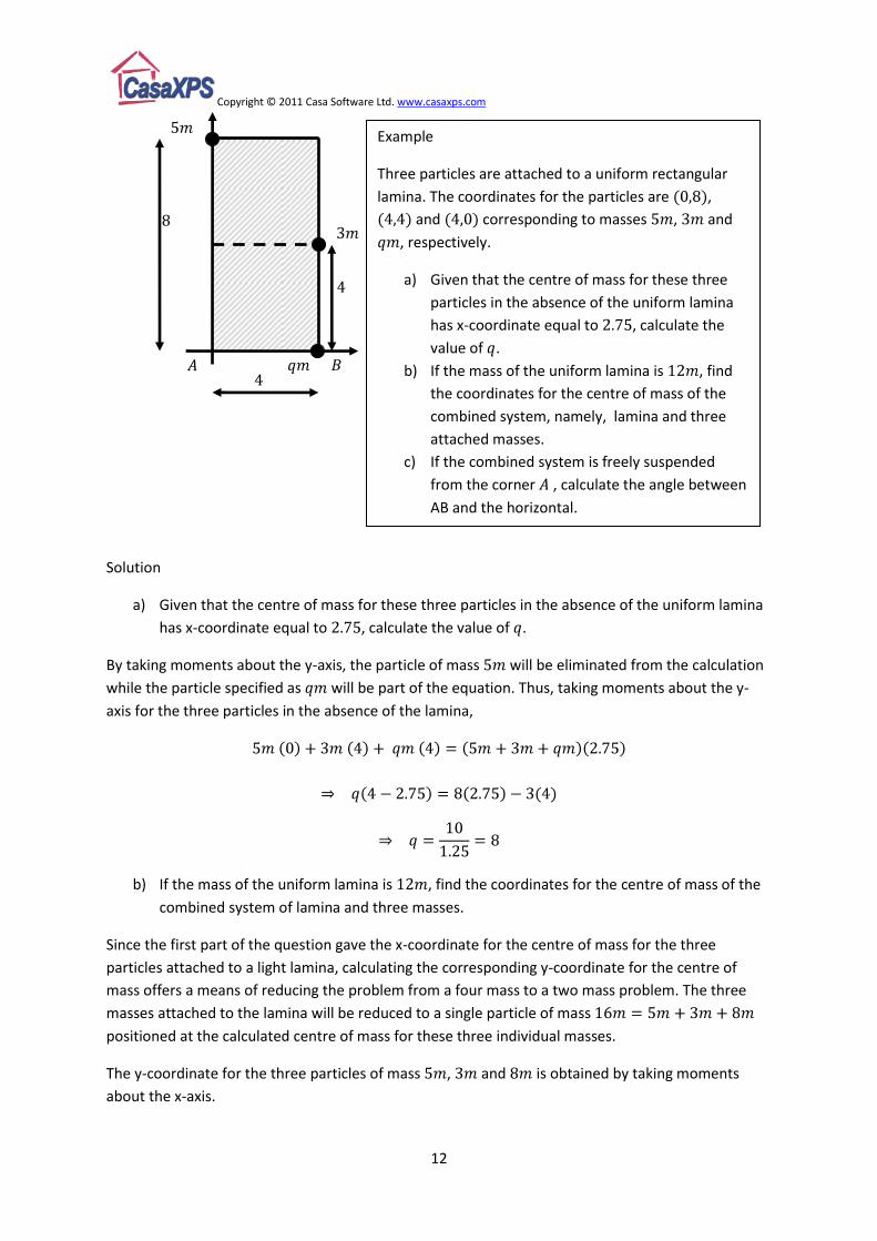
a) Given that the centre of mass for these three particles in the absence of the uniform lamina
has x-coordinate equal to , calculate the value of .
By taking moments about the y-axis, the particle of mass will be eliminated from the calculation
while the particle specified as will be part of the equation. Thus, taking moments about the y-
axis for the three particles in the absence of the lamina,
b) If the mass of the uniform lamina is , find the coordinates for the centre of mass of the
combined system of lamina and three masses.
Since the first part of the question gave the x-coordinate for the centre of mass for the three
particles attached to a light lamina, calculating the corresponding y-coordinate for the centre of
mass offers a means of reducing the problem from a four mass to a two mass problem. The three
masses attached to the lamina will be reduced to a single particle of mass
positioned at the calculated centre of mass for these three individual masses.
The y-coordinate for the three particles of mass , and is obtained by taking moments
about the x-axis.
Example
Three particles are attached to a uniform rectangular
lamina. The coordinates for the particles are ,
and corresponding to masses , and
, respectively.
a) Given that the centre of mass for these three
particles in the absence of the uniform lamina
has x-coordinate equal to , calculate the
value of .
b) If the mass of the uniform lamina is , find
the coordinates for the centre of mass of the
combined system, namely, lamina and three
attached masses.
c) If the combined system is freely suspended
from the corner , calculate the angle between
AB and the horizontal.
Copyright © 2011 Casa Software Ltd. www.casaxps.com
13
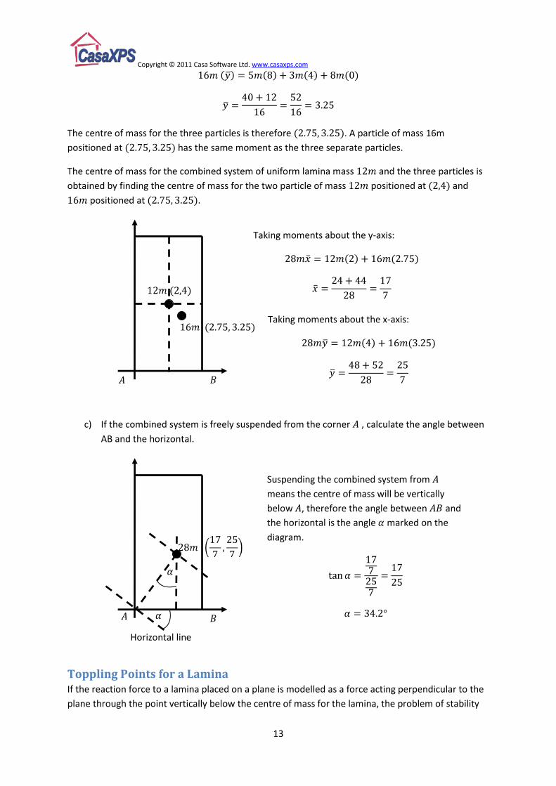
The centre of mass for the three particles is therefore . A particle of mass 16m
positioned at has the same moment as the three separate particles.
The centre of mass for the combined system of uniform lamina mass and the three particles is
obtained by finding the centre of mass for the two particle of mass positioned at and
positioned at .
c) If the combined system is freely suspended from the corner , calculate the angle between
AB and the horizontal.
Toppling Points for a Lamina If the reaction force to a lamina placed on a plane is modelled as a force acting perpendicular to the
plane through the point vertically below the centre of mass for the lamina, the problem of stability
Horizontal line
Suspending the combined system from
means the centre of mass will be vertically
below , therefore the angle between and
the horizontal is the angle marked on the
diagram.
Taking moments about the y-axis:
Taking moments about the x-axis:
Copyright © 2011 Casa Software Ltd. www.casaxps.com
14
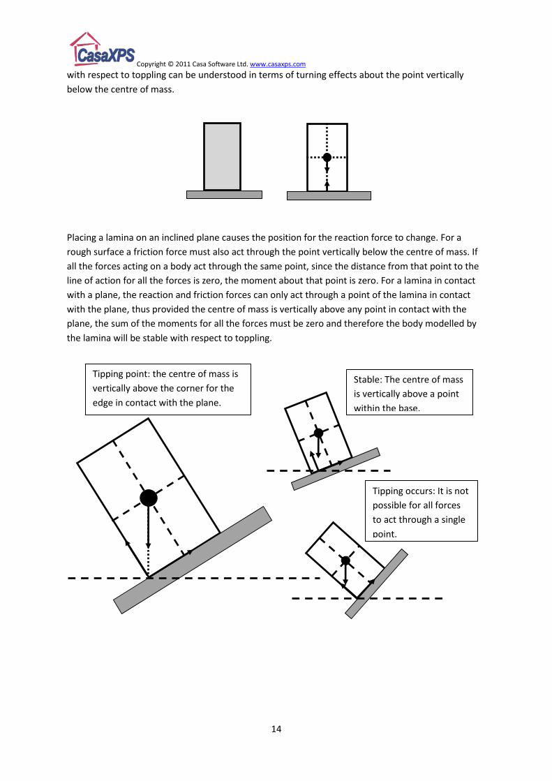
with respect to toppling can be understood in terms of turning effects about the point vertically
below the centre of mass.
Placing a lamina on an inclined plane causes the position for the reaction force to change. For a
rough surface a friction force must also act through the point vertically below the centre of mass. If
all the forces acting on a body act through the same point, since the distance from that point to the
line of action for all the forces is zero, the moment about that point is zero. For a lamina in contact
with a plane, the reaction and friction forces can only act through a point of the lamina in contact
with the plane, thus provided the centre of mass is vertically above any point in contact with the
plane, the sum of the moments for all the forces must be zero and therefore the body modelled by
the lamina will be stable with respect to toppling.
Tipping point: the centre of mass is
vertically above the corner for the
edge in contact with the plane.
Stable: The centre of mass
is vertically above a point
within the base.
Tipping occurs: It is not
possible for all forces
to act through a single
point.
Copyright © 2011 Casa Software Ltd. www.casaxps.com
15
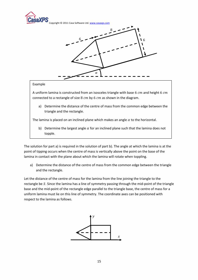
The solution for part a) is required in the solution of part b). The angle at which the lamina is at the
point of tipping occurs when the centre of mass is vertically above the point on the base of the
lamina in contact with the plane about which the lamina will rotate when toppling.
a) Determine the distance of the centre of mass from the common edge between the triangle
and the rectangle.
Let the distance of the centre of mass for the lamina from the line joining the triangle to the
rectangle be . Since the lamina has a line of symmetry passing through the mid-point of the triangle
base and the mid-point of the rectangle edge parallel to the triangle base, the centre of mass for a
uniform lamina must lie on this line of symmetry. The coordinate axes can be positioned with
respect to the lamina as follows.
Example
A uniform lamina is constructed from an isosceles triangle with base and height
connected to a rectangle of size by as shown in the diagram.
a) Determine the distance of the centre of mass from the common edge between the
triangle and the rectangle.
The lamina is placed on an inclined plane which makes an angle to the horizontal.
b) Determine the largest angle for an inclined plane such that the lamina does not
topple.

Copyright © 2011 Casa Software Ltd. www.casaxps.com
16
The y coordinate of centre-of-mass for the triangle, the rectangle and the combined lamina all have
the same value, namely, .
The distance is then calculated to be the same as the x coordinate for the centre of mass for the
lamina.
The centre of mass for the lamina is calculated using prior knowledge about the centre of mass of a
triangular uniform lamina and the centre of mass for a rectangular uniform lamina. If the mass per
unit area is , then the information used in calculating the centre of mass for the combined lamina is
as follows.
The centre of mass for any triangle, not just an isosceles triangle, lies on the median line passing
through a vertex and the mid-point of the opposite side to the triangle. It can be shown that the
distance from the mid-point of a side to the centre of mass is a third the length of the median line
passing through the opposite vertex. The distance from the y-axis for the triangular lamina of height
6 cm is therefore to the left of the y-axis so the x-coordinate for the centre of mass is .

Copyright © 2011 Casa Software Ltd. www.casaxps.com
17
Taking moments about the y-axis,
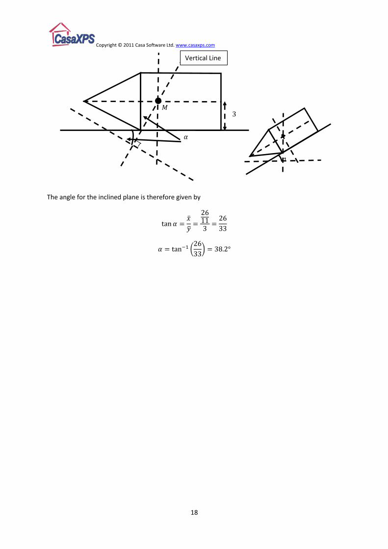
b) Determine the largest angle for an inclined plane such that the lamina does not topple.
The tipping point for the lamina placed on an inclined plane is determined by assuming the centre of
mass is vertically above the corner about which rotation can occur.
Median lines drawn from the
mid-point of a side to the
opposite vertex intersect at the
centre of mass for a scalene
triangle.
Copyright © 2011 Casa Software Ltd. www.casaxps.com
18
The angle for the inclined plane is therefore given by
Vertical Line

Copyright © 2011 Casa Software Ltd. www.casaxps.com
19
Solving Statics Problems The types of problem associated with statics include mechanical systems which do not move. For
example a ladder placed against a wall, where it is important for anyone climbing the ladder that it
does not move. These problems are analysed in terms of forces, friction and moments of forces.
Techniques used to analyse a statics problem in terms of forces are also used as part of dynamics
when determining the resultant force acting on a particle in motion. Statics at the level discussed in
this text is concerned with rigid bodies, not just particles, and as such requires the consideration of
turning effects of forces acting on rigid bodies. Turning effects of forces on rigid bodies are dealt
with using moments of forces which include an understanding of where the centre of mass for a
rigid body is located, which in turn is determined using moments of forces. The problems included in
this section therefore are not only the traditional statics problems, but will be supplemented by
elementary determination for the centre of mass for a mechanical system.
The problem as stated models the ladder as a rigid uniform rod of mass and the painter as a
particle of mass located at . The concept of a particle allows a complex shape like that of a
painter to be reduced to a point mass equivalent to the mass of the painter. Clearly a painter is not
rigid, thus replacing the painter by a point is a relatively crude form of mathematical modelling. The
rigid uniform rod similarly allows the weight of the ladder to act through the geometric centre of the
rod, which is, by virtue of the uniform rod assumption, the centre of mass for the rod. A ladder
replaced by a rod is a reasonably good mathematical model, and one that is more realistic than a
painter approximated by a particle.
The term geometric centre is used to describe a point at which all lines of symmetry meet.
When solving problems involving ladders, the first step is to annotate a diagram with the forces
acting on the mechanical system consisting of the ladder, the painter, the floor and the wall. Since
the ladder is modelled as a uniform rod of length , the centre of mass for the ladder is
Example
A painter places a ladder of length and mass
against a smooth vertical wall and on a rough
horizontal floor, such that the ladder is in a vertical
perpendicular plane with respect to the wall. The painter
of mass stands at point on the ladder such that
. The coefficient of friction between the
ground and the ladder is . If the ladder is on the point of
slipping, by modelling the ladder as a uniform rod and the
painter as a particle,
a) Show that the magnitude of the frictional force of
the ground on the ladder is .
b) Determine the angle made by the ladder with
the horizontal floor.

Copyright © 2011 Casa Software Ltd. www.casaxps.com
20
from . The particle is located from , therefore is from . The weight of the ladder
is and the weight of the particle is . In addition to these weights, since the ladder
stands on a rough floor, the diagram must include a normal reaction force and a friction force .
The direction for the friction force should be to oppose any potential movement the ladder would
make should the ladder begin to slip. The wall is smooth and therefore the contact point of the
ladder with the wall has no friction force parallel to the wall surface, but must include a normal
reaction force .
If the ladder and the painter are at rest, then the resultant force in any direction must be zero and
the sum of the moments about any point must be zero too.
a) Find the magnitude of the frictional force of the ground on the ladder.
The question states the ladder and painter are at the point where the ladder is about to slip, which
in mechanics terms means the friction force is at the maximum possible value. Since friction is a
passive force, the size of the friction force depends on the forces attempting to move the ladder, so
in general, if is the coefficient of friction and is the magnitude of the normal reaction force, then
the friction force obeys the relationship
And only attains the maximum value when in limiting equilibrium, that is, at the point just before the
ladder slips. The maximum friction force is obtained using . Since the coefficient of friction
between the ladder and the floor is given, namely, , the solution for the magnitude of the
friction force requires the determination of the normal reaction force at .
For a body at rest, the resultant force in any direction must be zero, and in particular, since the
normal reaction force at A acts vertically, resolving the forces vertically yields
Copyright © 2011 Casa Software Ltd. www.casaxps.com
21
Thus, the magnitude of the friction force is given by
b) Determine the angle made by the ladder with the horizontal floor.
The angle is obtained by generating equations involving lengths and forces. For a rigid body to be
in equilibrium, the moments of the forces taken about any point must sum to zero. Since the
condition for equilibrium must be satisfied for any point, the best point to choose is a point on the
ladder which simplifies the resulting equations. Taking moments about eliminates the normal
reaction force and the friction force from the equations.
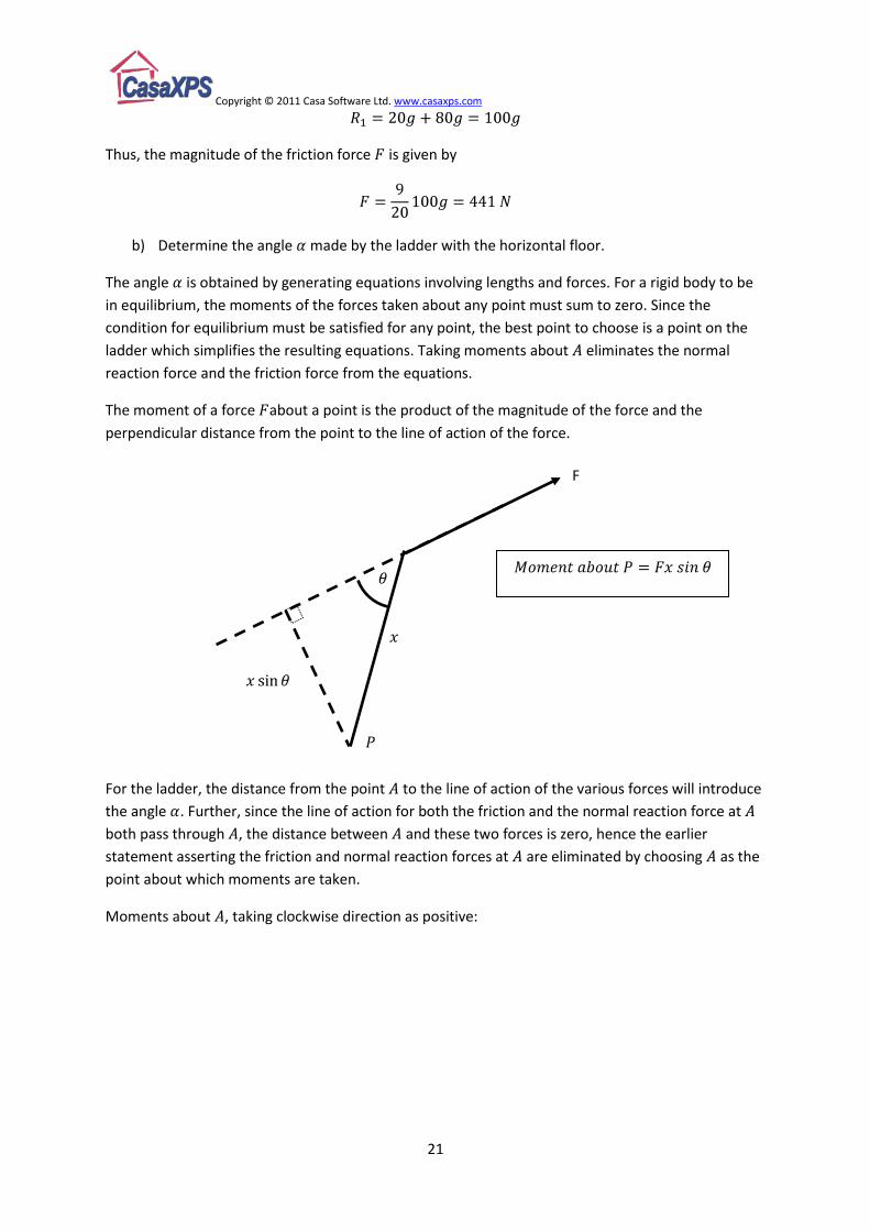
The moment of a force about a point is the product of the magnitude of the force and the
perpendicular distance from the point to the line of action of the force.
For the ladder, the distance from the point to the line of action of the various forces will introduce
the angle . Further, since the line of action for both the friction and the normal reaction force at
both pass through , the distance between and these two forces is zero, hence the earlier
statement asserting the friction and normal reaction forces at are eliminated by choosing as the
point about which moments are taken.
Moments about , taking clockwise direction as positive:
F

Copyright © 2011 Casa Software Ltd. www.casaxps.com
22
Therefore, summing the moments about yields:
This equation involves two unknowns, therefore another equation is required involving .
Resolving the forces in the horizontal direction .
Moment about for Weight of Ladder
Moment about for Weight of particle at
Moment about for Normal Reaction Force at Wall
Copyright © 2011 Casa Software Ltd. www.casaxps.com
23
The ladder and loads, in this example, are designed to illustrate how more involved problems can be
solved by reducing the system of masses to an effective mass acting through the centre of mass for
the ladder together with the particles attached to the ladder.
While the ladder and masses are ultimately placed against a wall at an angle, the underlying
collection of masses can be reduced to a single mass acting through the centre of mass. This
principle is already applied to the concept of a uniform rod, where the mass representing the ladder
acts through the geometric centre for the rod. We now wish to find the position on the ladder where
a single mass attached to a light rod would produce the same result as analysing the masses and
ladder as separate entities.
To calculate the centre of mass, the idea is to determine the turning effect about some point of the
heavy rod (uniform rod-with-mass) and the three masses and determine the moment for a particle
with mass equal to the total mass (the ladder plus the three masses) attached to a light rod, such
that the moments for these two systems of masses and rods are exactly the same.
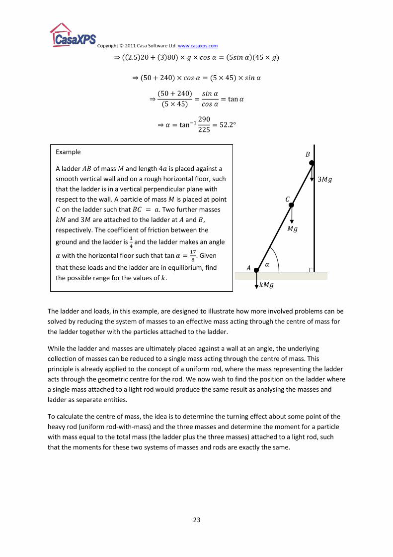
Example
A ladder of mass and length is placed against a
smooth vertical wall and on a rough horizontal floor, such
that the ladder is in a vertical perpendicular plane with
respect to the wall. A particle of mass is placed at point
on the ladder such that . Two further masses
and are attached to the ladder at and ,
respectively. The coefficient of friction between the
ground and the ladder is and the ladder makes an angle
with the horizontal floor such that . Given
that these loads and the ladder are in equilibrium, find
the possible range for the values of .
Copyright © 2011 Casa Software Ltd. www.casaxps.com
24
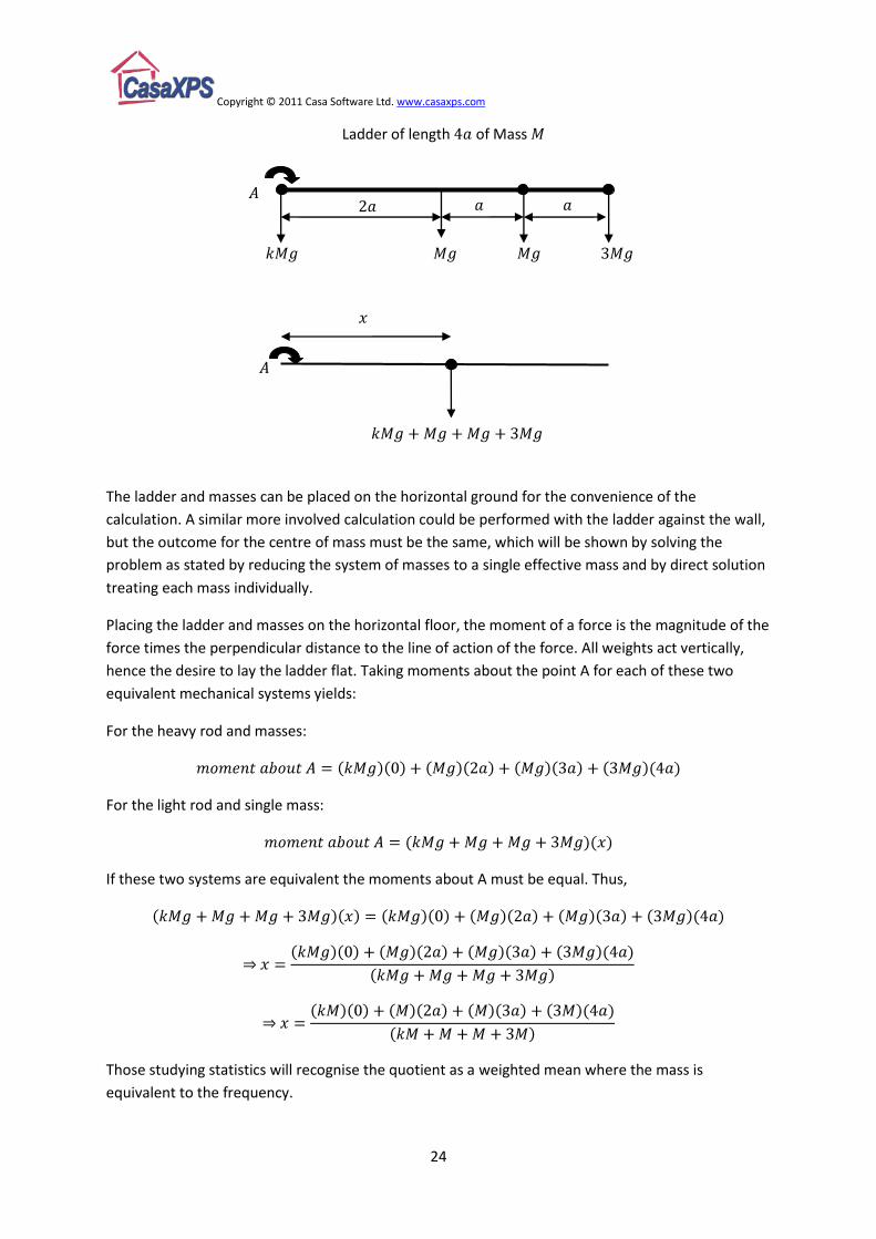
The ladder and masses can be placed on the horizontal ground for the convenience of the
calculation. A similar more involved calculation could be performed with the ladder against the wall,
but the outcome for the centre of mass must be the same, which will be shown by solving the
problem as stated by reducing the system of masses to a single effective mass and by direct solution
treating each mass individually.
Placing the ladder and masses on the horizontal floor, the moment of a force is the magnitude of the
force times the perpendicular distance to the line of action of the force. All weights act vertically,
hence the desire to lay the ladder flat. Taking moments about the point A for each of these two
equivalent mechanical systems yields:
For the heavy rod and masses:
For the light rod and single mass:
If these two systems are equivalent the moments about A must be equal. Thus,
Those studying statistics will recognise the quotient as a weighted mean where the mass is
equivalent to the frequency.
Ladder of length of Mass

Copyright © 2011 Casa Software Ltd. www.casaxps.com
25
The original problem is then reduced to a light rod and a single particle:
The solution to the original problem then proceeds by listing the equations generated by resolving
the forces vertically and horizontally as indicated on the diagram, the relationship between friction
force and the normal reaction force of the ladder on the floor and taking moments about A.
Resolving vertically:
Resolving horizontally:
Finally taking moments about A:
Coefficient of friction:
Equation (1) yields , therefore
Equation (2) shows that and substituting for and Equation (3) gives

Copyright © 2011 Casa Software Ltd. www.casaxps.com
26
Since ,
Substituting into Equation (5) provides the inequality
For equilibrium, the ladder must have a mass placed at A where, .
The alternative to reducing the ladder and masses to a single mass is the direct approach where all
the forces for each explicit particle and the ladder are detailed on the diagram. The solution
proceeds with exactly the same steps, the difference being the complexity of the equations
generated from resolving vertically and taking moments about the point . Taking a complex system
and reducing the system to an equivalent simpler system is a common theme in higher mathematics,
and thinking in terms of the centre of mass is a good example illustrating this approach. It also
explains why calculating the centre of mass for complex rigid bodies features in most mechanics
courses.
Resolving vertically:
Moments about A:
These equations should be compared to Equations
(1) and (3) above. The result obtained from these
equations is the same as when the ladder and
particles are reduced to a single mass acting at the
centre of mass for the system.

Copyright © 2011 Casa Software Ltd. www.casaxps.com
27
The essential difference between a problem involving a ladder leaning against a wall and a rod
supported by a peg is at the contact point for the rod. If the peg and the wall are smooth, that is the
contact point between the rod and either the wall or the peg has no friction force therefore only
involves a normal reaction force, the difference between these two problems is the direction for the
reaction force. The normal reaction force of the ladder in contact with a vertical wall is horizontal,
while for the smooth peg, the direction for the normal reaction force depends on the angle between
the rod and the floor.
If a ladder were placed on top of a smooth wall, the problem reduces to that of a smooth peg.
Normal
reaction force
for a ladder
against a
smooth wall Normal reaction force for a rod supported by
a smooth peg
Example
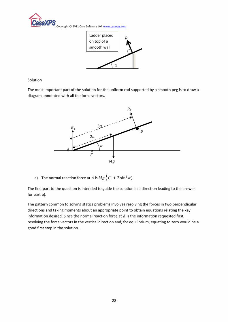
A uniform rod of length and mass rests in equilibrium with one end in contact with a
rough horizontal surface at , and is supported by a smooth peg at position where
. When in limiting equilibrium, the rod makes an angle with the horizontal surface. Show
that
a) The normal reaction force at is .
b) The coefficient of friction can be expressed in terms of the angle by
Copyright © 2011 Casa Software Ltd. www.casaxps.com
28
Solution
The most important part of the solution for the uniform rod supported by a smooth peg is to draw a
diagram annotated with all the force vectors.
a) The normal reaction force at is .
The first part to the question is intended to guide the solution in a direction leading to the answer
for part b).
The pattern common to solving statics problems involves resolving the forces in two perpendicular
directions and taking moments about an appropriate point to obtain equations relating the key
information desired. Since the normal reaction force at is the information requested first,
resolving the force vectors in the vertical direction and, for equilibrium, equating to zero would be a
good first step in the solution.
Ladder placed
on top of a
smooth wall
Copyright © 2011 Casa Software Ltd. www.casaxps.com
29
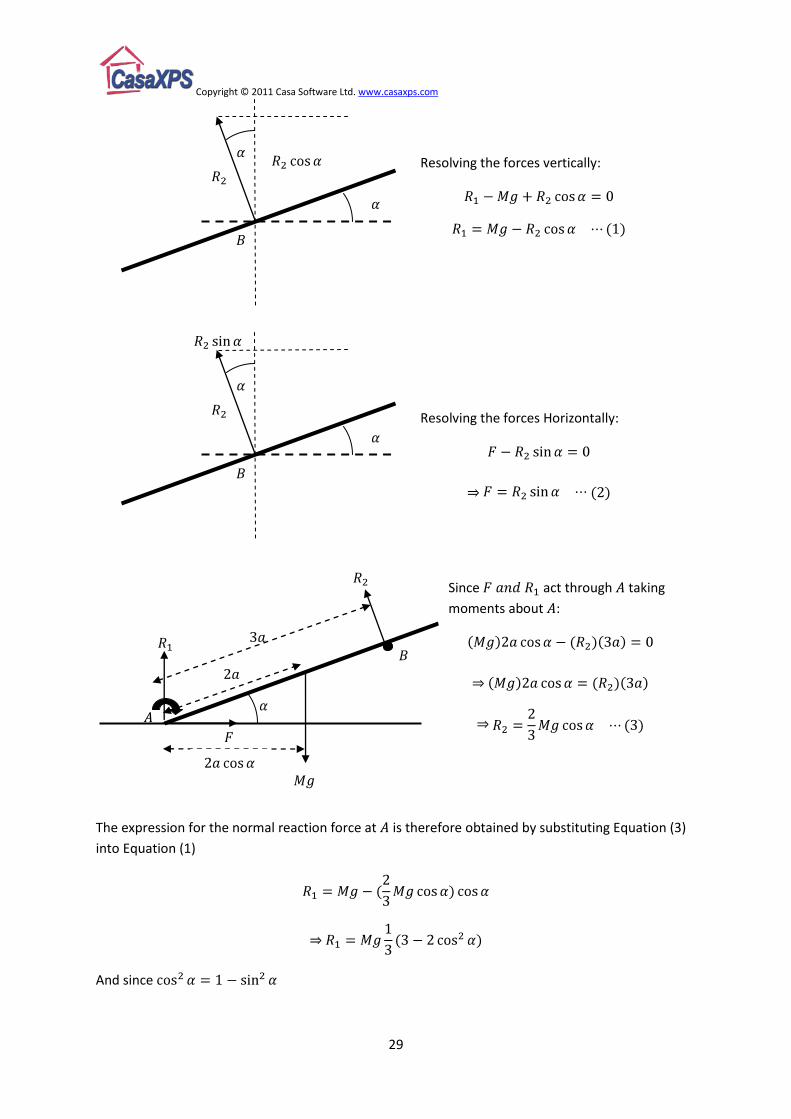
The expression for the normal reaction force at is therefore obtained by substituting Equation (3)
into Equation (1)
And since
Since act through taking
moments about :
Resolving the forces Horizontally:
Resolving the forces vertically:
Copyright © 2011 Casa Software Ltd. www.casaxps.com
30
b) The coefficient of friction can be expressed in terms of the angle .
For limiting equilibrium
Substituting Equation (2) into Equation (5)
Substituting from Equation (3), and from Equation (4)
And since ,

Copyright © 2011 Casa Software Ltd. www.casaxps.com
31
The force acting at is not specified by a magnitude or direction. Since so little is known about the
force at the solution is likely to involve taking moments about , as in so doing the resulting
equation for equilibrium of the rod will not require any knowledge about the force at . Further,
since the coefficient of friction is given, the friction force is known in terms of the normal reaction at
, so taking moments about and substituting into the resulting equation allows the
normal reaction to be determined.
Since , and ,
For equilibrium Moments about
Example
A uniform rod of length and mass rests with one end on a rough horizontal
plane. A force is applied to the rod at a point which is from such that the rod is held in
limiting equilibrium at an angle to the horizontal, where . The line of action of the
force at is in the same vertical plane as the rod. Given that the coefficient of friction between
the rod and the horizontal plane is , find the magnitude of the normal reaction force of the
ground on the rod at .
Copyright © 2011 Casa Software Ltd. www.casaxps.com
32
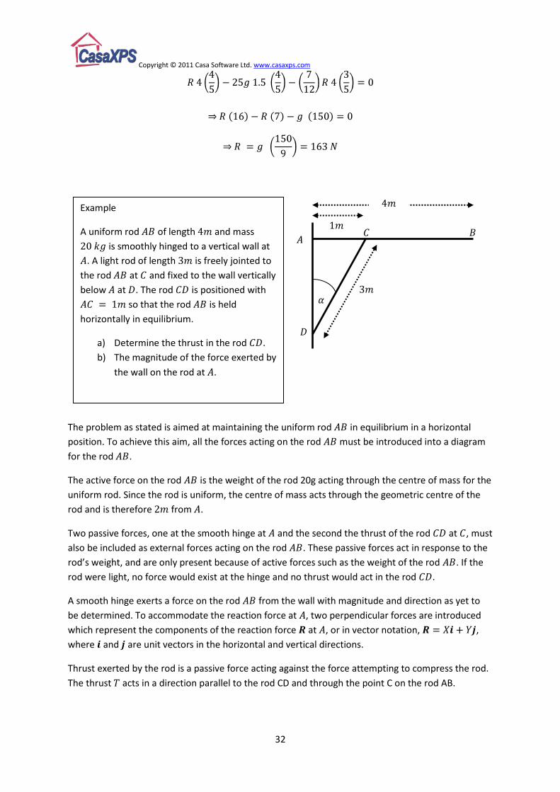
The problem as stated is aimed at maintaining the uniform rod in equilibrium in a horizontal
position. To achieve this aim, all the forces acting on the rod must be introduced into a diagram
for the rod .
The active force on the rod is the weight of the rod 20g acting through the centre of mass for the
uniform rod. Since the rod is uniform, the centre of mass acts through the geometric centre of the
rod and is therefore from .
Two passive forces, one at the smooth hinge at and the second the thrust of the rod at , must
also be included as external forces acting on the rod . These passive forces act in response to the
rod’s weight, and are only present because of active forces such as the weight of the rod . If the
rod were light, no force would exist at the hinge and no thrust would act in the rod .
A smooth hinge exerts a force on the rod from the wall with magnitude and direction as yet to
be determined. To accommodate the reaction force at , two perpendicular forces are introduced
which represent the components of the reaction force at , or in vector notation, ,
where and are unit vectors in the horizontal and vertical directions.
Thrust exerted by the rod is a passive force acting against the force attempting to compress the rod.
The thrust acts in a direction parallel to the rod CD and through the point C on the rod AB.
Example
A uniform rod of length and mass
is smoothly hinged to a vertical wall at
. A light rod of length is freely jointed to
the rod at and fixed to the wall vertically
below at . The rod is positioned with
so that the rod is held
horizontally in equilibrium.
a) Determine the thrust in the rod .
b) The magnitude of the force exerted by
the wall on the rod at .
Copyright © 2011 Casa Software Ltd. www.casaxps.com
33
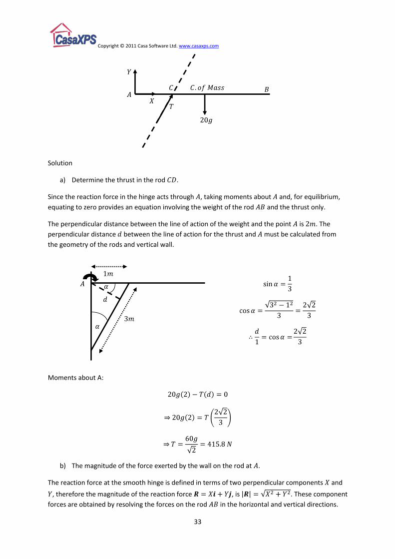
Solution
a) Determine the thrust in the rod .
Since the reaction force in the hinge acts through , taking moments about and, for equilibrium,
equating to zero provides an equation involving the weight of the rod and the thrust only.
The perpendicular distance between the line of action of the weight and the point is . The
perpendicular distance between the line of action for the thrust and must be calculated from
the geometry of the rods and vertical wall.
Moments about A:
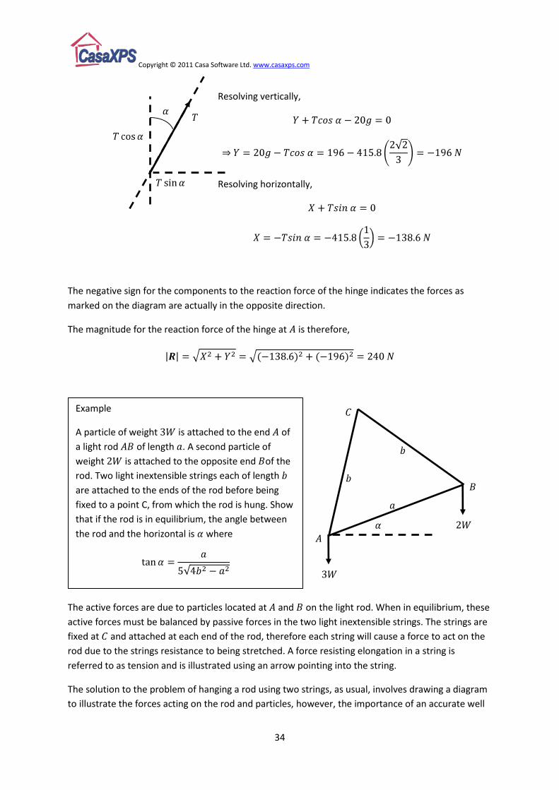
b) The magnitude of the force exerted by the wall on the rod at .
The reaction force at the smooth hinge is defined in terms of two perpendicular components and
, therefore the magnitude of the reaction force , is . These component
forces are obtained by resolving the forces on the rod in the horizontal and vertical directions.
Copyright © 2011 Casa Software Ltd. www.casaxps.com
34
The negative sign for the components to the reaction force of the hinge indicates the forces as
marked on the diagram are actually in the opposite direction.
The magnitude for the reaction force of the hinge at is therefore,
The active forces are due to particles located at and on the light rod. When in equilibrium, these
active forces must be balanced by passive forces in the two light inextensible strings. The strings are
fixed at and attached at each end of the rod, therefore each string will cause a force to act on the
rod due to the strings resistance to being stretched. A force resisting elongation in a string is
referred to as tension and is illustrated using an arrow pointing into the string.
The solution to the problem of hanging a rod using two strings, as usual, involves drawing a diagram
to illustrate the forces acting on the rod and particles, however, the importance of an accurate well
Example
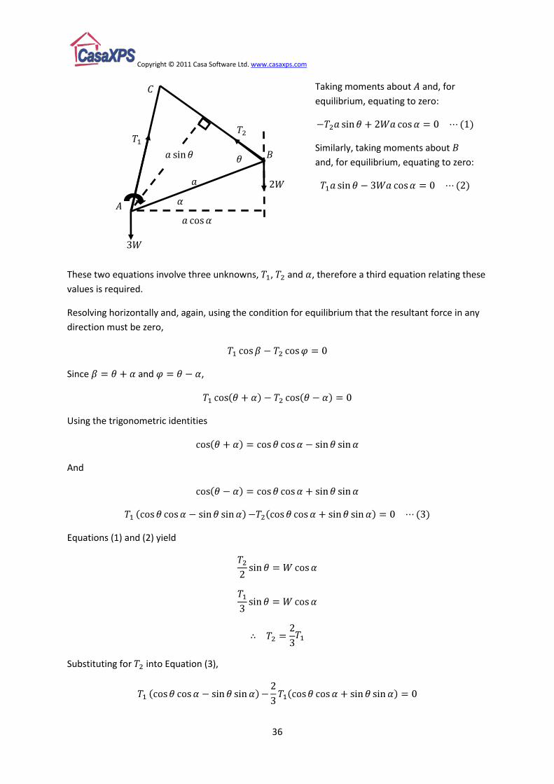
A particle of weight is attached to the end of
a light rod of length . A second particle of
weight is attached to the opposite end of the
rod. Two light inextensible strings each of length
are attached to the ends of the rod before being
fixed to a point C, from which the rod is hung. Show
that if the rod is in equilibrium, the angle between
the rod and the horizontal is where
Resolving vertically,
Resolving horizontally,
Copyright © 2011 Casa Software Ltd. www.casaxps.com
35
drawn diagram is clearly shown by this example. Without a clear geometric understanding for the
system of strings, particles and rod, the solution is more difficult to see. The problem is posed to
extract a higher than usual mathematical content for mechanics questions, but would certainly
require an even higher mathematical intuition without a pictorial understanding of the components
involved.
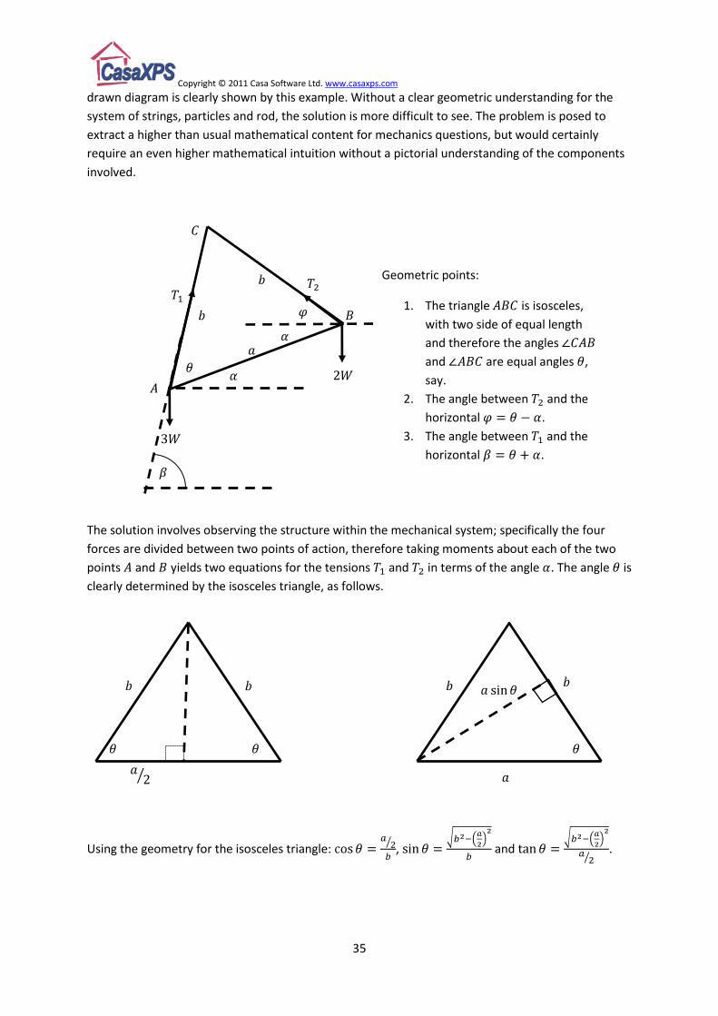
The solution involves observing the structure within the mechanical system; specifically the four
forces are divided between two points of action, therefore taking moments about each of the two
points and yields two equations for the tensions and in terms of the angle . The angle is
clearly determined by the isosceles triangle, as follows.
Using the geometry for the isosceles triangle: , and .
Geometric points:
1. The triangle is isosceles,
with two side of equal length
and therefore the angles
and are equal angles ,
say.
2. The angle between and the
horizontal .
3. The angle between and the
horizontal .
Copyright © 2011 Casa Software Ltd. www.casaxps.com
36
These two equations involve three unknowns, , and , therefore a third equation relating these
values is required.
Resolving horizontally and, again, using the condition for equilibrium that the resultant force in any
direction must be zero,
Since and ,
Using the trigonometric identities
And
Equations (1) and (2) yield
Substituting for into Equation (3),
Taking moments about and, for
equilibrium, equating to zero:
Similarly, taking moments about
and, for equilibrium, equating to zero:
Copyright © 2011 Casa Software Ltd. www.casaxps.com
37
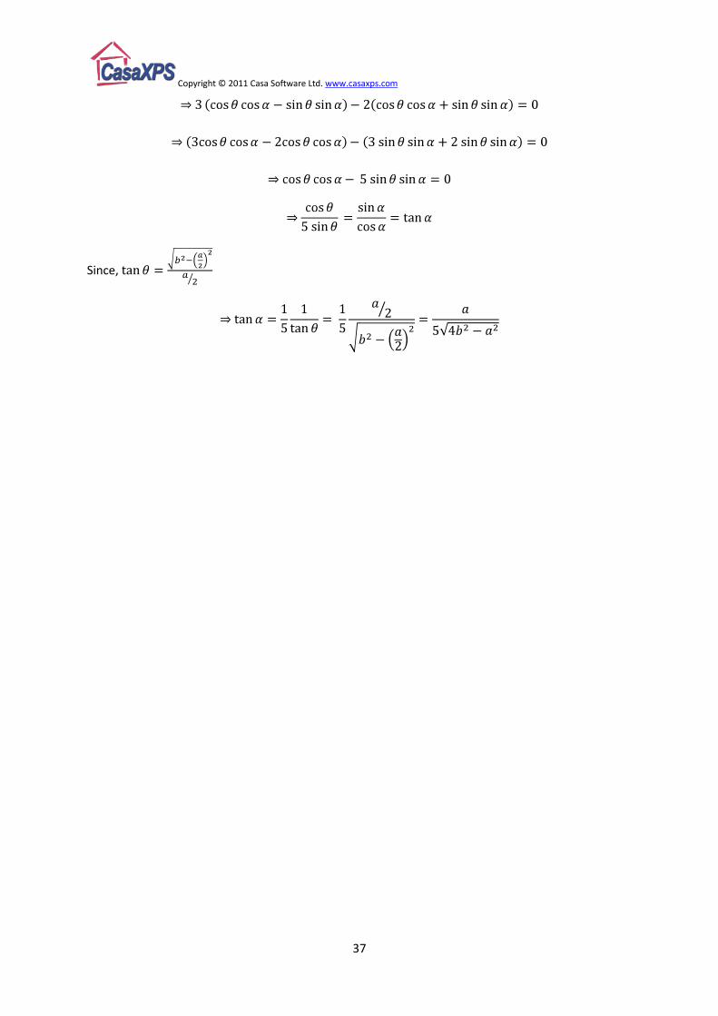
Since,