Embed Size (px)
Citation preview

Central Management SystemUser Manual
Version 1.05

Copyright Statement
This manual may not be reproduced in any form or by any means to create any derivative such astranslation, transformation, or adaptation without the prior written permission of MilesightTechnology Co., Ltd(Hereinafter referred to as Milesight).
Milesight reserves the right to change this manual and the specifications without prior notice. Thelatest specifications and user documentation for all Milesight products are available on our officialwebsite www.milesight.com.

Content
1. Introduction............................................................................................................................................................ 11.1 Introduction....................................................................................................................................................11.2 Key Features.................................................................................................................................................. 11.3 System Requirements.................................................................................................................................... 1
2. Installation.............................................................................................................................................................. 22.1 Installation Guide...........................................................................................................................................22.2 Login/Logout................................................................................................................................................. 5
2.2.1 Login...................................................................................................................................................52.2.2 Logout................................................................................................................................................ 7
3. Manage.................................................................................................................................................................... 83.1 Device Management...................................................................................................................................... 8
3.1.1 Adding Devices..................................................................................................................................83.1.2 Removing or Logging Out the Device............................................................................................ 113.1.3 Logout the Added Device............................................................................................................... 123.1.4 Editing Device..................................................................................................................................14
3.2 Device Config..............................................................................................................................................153.2.1 NVR...................................................................................................................................................153.2.2 Camera............................................................................................................................................. 33
3.3 Users............................................................................................................................................................ 464. View....................................................................................................................................................................... 47
4.1 Live View.....................................................................................................................................................474.1.1 Live view interface..........................................................................................................................484.1.2 Settings of Display the Live View...................................................................................................50
4.2 Playback.......................................................................................................................................................545. Tools.......................................................................................................................................................................56
5.1 E-Map.......................................................................................................................................................... 565.2 Logs..............................................................................................................................................................57
6. Service................................................................................................................................................................... 586.1 Service..........................................................................................................................................................58

File Format:MS-QR-JS-04 Rev1.0 Durability Date:1Years1
1. Introduction
1.1 Introduction
The Milesight Central Management System(hereinafter referred to as CMS) software works togive you access and control of your Milesight High Definition Surveillance System. The MilesightCMS provides multiple operating functionalities, including live view, PTZ control, video playback,motion detection, alarm receiving, log and so on.
This user manual describes the function, configuration and operation steps of CMS. To ensure theproper usage and stability of the CMS, please refer to the contents below and read the manualcarefully before operation.
The latest version of the software will be available on our official website. Please check our officialwebsite www.milesight.com for upgrading.
1.2 Key Features
Support NVR as well as camera Support 1/ 4/ 8/ 9/ 16/ 36/ 64 channels playing synchronously Full screen for single or multiple channels Support four monitors Support modifying video / image parameters of camera H.265/H.264/MJPEG/MPEG-4 video compression Support dual-stream Support multiple PTZ control protocols Support custom time length for schedule record Motion detection, alarm recording and image capture function Easy to install and use Support back up NVR files from playback Configuration feature for record/alarm in/alarm out/video loss/motion Support edit privilege for specific user CPU/Memory info in the live view
1.3 System Requirements
OS: Windows XP/7/8/10/Vista/Server 2000/Server 2008CPU: 2.4GHZ or fasterMemory: 2G MB or moreGraphic memory: 1G or moreInternet protocol: TCP/IP

File Format:MS-QR-JS-04 Rev1.0 Durability Date:1Years2
2. Installation
2.1 Installation Guide
Run the installation file and install the programs on your computer by following the on-screeninstructions. After finishing installation, you will find the programs on the start menu or on thedesktop.
Step1: Click the installation file to install;
Figure 2-1-1 Start Setup

File Format:MS-QR-JS-04 Rev1.0 Durability Date:1Years3
Step2: Choose the folder in which to install Milesight CMS;
Figure 2-1-2 Choose File Path
Step3: Choose Start Menu Folder for the Milesight CMS;
Figure 2-1-3 Choose the Start Menu

File Format:MS-QR-JS-04 Rev1.0 Durability Date:1Years4
Step4: Finish the Setup:
Figure 2-1-4 Finish the Setup

File Format:MS-QR-JS-04 Rev1.0 Durability Date:1Years5
2.2 Login/Logout
2.2.1 Login
Double click the icon to start the software, then choose the user and enter the password, the
default account Username is: admin; Password is: password. You can check the checkbox toremember the password, then you can auto login by choosing Auto Login.
Figure 2-2-1 Log In
After login into the system, you can see the Live View page as follows:
Figure 2-2-2 Live View

File Format:MS-QR-JS-04 Rev1.0 Durability Date:1Years6
And the meanings of the icons on the top-right are as follows:
Table 2-2-1 Live View
Item Function Introduction
User name
Click the button to lock the software, and it needs to enter the password tounclock
Menu button
Minimize the interface
Restore Down the interface
Maximize the interface
Close the software
To check the hidden pages when the windows is too small to show all theopened pages
To check the real-time CPU status on PC
To check the real-time RAM memory on PC
Click the Menu button , the interface is as follows:
Language , Log Retention Period, Video Save Path, Snapshot SavePath, Auto Login, Run CMS when Windows startup, High NetworkPerformance Mode and Better Image QualityAdjust the windows to meet your needInformation of the CMSLog out of the current accountClose the software
Note CMS currently supports 5 languages: English, Smplified Chinese, Traditional Chinese, Russian and Korean. High Network Performance Mode: Optimize the speed of switching stream.

File Format:MS-QR-JS-04 Rev1.0 Durability Date:1Years7
2.2.2 Logout
Click →[Log out] to exit the current account, or click to exit the CMS.
Figure 2-2-3 Log Out
Note Password is necessary for logging out.

File Format:MS-QR-JS-04 Rev1.0 Durability Date:1Years8
3.Manage
3.1 Device Management
The Milesight CMS supports to add Milesight cameras and NVRs to get an efficient and convenientmanagement. The devices also can be removed or logged out from the CMS at any time.
3.1.1 Adding Devices
There are two measures available for adding devices. First of all, click the Add button [+]→[Device].
Figure 3-1-1 Adding Device
Adding a Single DeviceMilesight CMS provides to add device one by one. Please refer to the steps as follows:
Step1: Click the button;Step2: Select the device type, “NVR” or “Camera”;Step3: Enter device information;

File Format:MS-QR-JS-04 Rev1.0 Durability Date:1Years9
Figure 3-1-2 Adding Device Manually
The meanings of the items on the page can be referred to the table 3-1-1.
Table 3-1-1 Adding Device Manually
Item Function Introduction
Device Type Camera and NVR are available
Name Name of the device
IP Address The IP address of the device
Port The port of the device, the default port is 80, old model is 1100
User Name The user name of the device, the default user name is “admin”
Password
Enter the password for the account of the device, and defaultpassword for:1. Network Camera: ms12342. NVR:For version *.7.0.6 and above: ms1234For version *.7.0.5 and below: 123456
Transport Protocol TCP and UDP are available
Stream ModeThere are three options, “Auto”, “Primary Stream” and “SecondaryStream”
Once the device has been added successfully, a window will pop up as follows:
Figure 3-1-3 Adding Device Successfully

File Format:MS-QR-JS-04 Rev1.0 Durability Date:1Years10
SearchMilesight CMS can search devices which are in the same network automatically, and it can adddevices which have the same user name and password in bulk. Please refer to the steps as follows:
Step1: Click button to search the Milesight devices in the same network;
Step2: Select the devices;Step3: Enter the user name and password of the selected devices, and the default ones are
“admin” and “password” ;
Step4: Click button, a window will pop up to inform you whether the devices are added
successfully or not.Step5: Click the [OK] button;Step6: Click [Refresh] button to refresh the status of the added devices.
Figure 3-1-4 Adding Group Device
Note
Clicking button to refresh the status of the added devices.
Clicking button can select all devices which were found; The devices found can be sorted by their IP, Port, Type, MAC, Model when you click the corresponding button. Up to 64 devices can be added;

File Format:MS-QR-JS-04 Rev1.0 Durability Date:1Years11
3.1.2 Removing or Logging Out the Device
Milesight CMS can remove single/bulk added devices. First of all, enter [Device Manage] andfollow the steps:
Removing a Single DeviceThe steps to remove a Single device are as follows:
Step1: Click the button followed by the selected device;
Step2: Click [OK] to remove the device or [Cancel] button to cancel the action when the windowpops up;
Figure 3-1-5 Removing a single Device
Removing Group DevicesThe steps to remove the devices for a group are as follows:Step1: Click to select all the added devices or check the checkbox to select
several devices;
Step2: Click the to remove the selected devices;Step3: Click the [OK] to remove the devices or [Cancel] button to cancel the action when the
window pops up;

File Format:MS-QR-JS-04 Rev1.0 Durability Date:1Years12
Figure 3-1-6 Removing Group Device
3.1.3 Logout the Added Device
You can log out the added device rather than remove it in case that the device will be neededagain. Log-out means that the device is disabled for the present.
You can click the button to log out the device, and the icon will turn into ;
Figure 3-1-7 Logging Out the Added Device on Device Management PageOr right-click the selected device and choose [Log out].

File Format:MS-QR-JS-04 Rev1.0 Durability Date:1Years13
Figure 3-1-8 Logging Out the Added Device on Live View Page
Note
You can click the button on Device Management page or right-click the device on Live View page and
choose [Log in] to log in again.

File Format:MS-QR-JS-04 Rev1.0 Durability Date:1Years14
3.1.4 Editing Device
Click the Edit button to edit the added device. All parameters can be edited except the
Device Type and IP address. See as follows:
Figure 3-1-9 Editing Device
The meanings of parameters can be referred to the table 3-1-1.

File Format:MS-QR-JS-04 Rev1.0 Durability Date:1Years15
3.2 Device Config
In the Device Config, there are Channels, Event, Record and System parts for NVR, and Video,Event, Record and System for Camera configurations.
3.2.1 NVR
The NVR Configuration page is as follows:
Figure 3-2-1 NVR Page
3.2.1.1 Channels
ChannelsChannels management provides searching, adding, editing, deleting channels function. As forsearching and deleting channels, please refer to the Chapter III Device Management 3.1 AddingDevice.

File Format:MS-QR-JS-04 Rev1.0 Durability Date:1Years16
Figure 3-2-2 Channels Management[Adding Channel]You can add Milesight cameras searched by CMS automatically, and by adding manually, you canadd third party cameras that have ONVIF and RTSP protocol.
Figure 3-2-3 Adding Channel

File Format:MS-QR-JS-04 Rev1.0 Durability Date:1Years17
ONVIF: Camera which supports ONVIF protocol;RTSP: Primary: rtsp://IP:Port/main
Secondary: rtsp://IP:Port/sub(The default port for RTSP protocol is 554.)
MSSP is only for the Milesight products.
[Editing Channel]
You can edit the channel when adding it manually. Or you can edit it by click the button .
Figure 3-2-4 Editting Channel
3.2.1.2 Event
ExceptionClick the Exception button, the setting window will pop up as follows:

File Format:MS-QR-JS-04 Rev1.0 Durability Date:1Years18
Figure 3-2-5 Exception
The meanings of the items on the Exception page can be referred to the table 3-2-1 below:
Table 3-2-1 Schedule
Item Function Introduction
Exception TypeThere are “Network Disconnected”、“HDD Full”、“Record Failed”&
“HDD Failed”、“HDD Unformat”、“NO Disk”
Normal Linkage
Enable or disable the Pop Up Alarm
Enable or disable the Audio Warnings
Enable or disable the E-mail Linkage
After finishing the settings, you can click the Apply button to apply your settings tothe CMS software.
Alarm I/OClick the Alarm I/O button, the setting window will pop up as follows, you can configurate alarminput and output information:

File Format:MS-QR-JS-04 Rev1.0 Durability Date:1Years19
Figure 3-2-6 Alarm Input / Output
The “Alarm Input” settings offers you to set up alarm input type, effective time, and correspondingtriggers.The “Alarm Output” settings offers you to set up alarm output type and effective time.
After setting up one channel, click the Apply button , and then click the Copy button
to copy the settings to other channels.
File Format:MS-QR-JS-04 Rev1.0 Durability Date:1Years20
3.2.1.3 Record
ScheduleClick the Schedule button, the setting window will pop up as follows:
Figure 3-2-7 Record Schedule
You can set channel recording schedules in “Record Schedule”, and there are three status “NoRecord”, “Always Record” and “Record by schedule”. If you want the channels to record byschedule, you need to select the “Record by Schedule” check box and click “Edit Schedule” to setup, or otherwise the recording schedule is not allowed to be edited.
Step1: Enabling “Record by Schedule”Step2: Click the “Edit Schedule” button, then the setting window will pop up as follows:
Figure 3-2-8 Edit Schedule

File Format:MS-QR-JS-04 Rev1.0 Durability Date:1Years21
After setting the schedule for one channel, click the Apply button , and then click the
Copy button to copy to other channels. [Advanced Schedule Settings] are as follows:
Figure 3-2-9 Schedule Advanced
The meanings of the items on the Schedule page can be referred to the table 3-2-2 below:
Table 3-2-2 Schedule
Item Function Introduction
Channel Select the channel to set
Post Record Enable or disable the Post Record function
Duration Time The duration time of post record
Audio Record Enable or disable the Audio Record
Record Stream Type Main and Sub stream are available
Due Time Set how many days the record will be kept

File Format:MS-QR-JS-04 Rev1.0 Durability Date:1Years22
After finishing the settings, you can click the Copy button to copy the settings to the
other channels. Click the Apply button to apply your settings to the CMS software.
Figure 3-2-10 Copy to Other Channels
HolidayClick the Holiday button, the Holiday window will pop up. Click the Edit button to edit the selectedholiday schedule as follows:
Figure 3-2-11 Holiday
File Format:MS-QR-JS-04 Rev1.0 Durability Date:1Years23
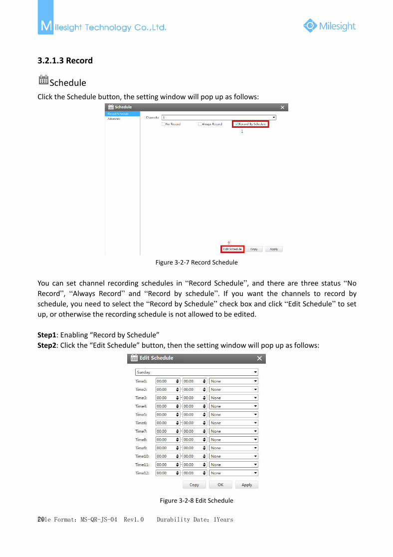
Disk ManagementClick the Disk Management to manage the disk, as the window shows, you can check the diskstatus and format the disk. You can draw the blue bar to get more information about the disk.
Figure 3-2-12 Disk Management

File Format:MS-QR-JS-04 Rev1.0 Durability Date:1Years24
3.2.1.4 System
There are five parts in the System pages: General, Network, User, Status, Maintenance.
General
Click the General button , a window will pop up as follows:
Figure 3-2-13 General
Device name and ID can be made up by yourself, and Server Time depends on the time zone anddaylight saving time you choose, which can be synchronized through NTP or manually. After
complete the settings, click to save and apply the settings to CMS.
NetworkIn the Network part, you can use several network functions.
[Basic]Basic configuration includes working mode, IP Address, NetMask, Gateway, MTU, DNS server, etc.

File Format:MS-QR-JS-04 Rev1.0 Durability Date:1Years25
Figure 3-2-14 Basic
[DDNS]DDNS (Dynamic Domain Name System) solves the dynamic IP address problems.
Figure 3-2-15 DDNS
[Mail]Check whether the SMTP port can be set or not. Please enable SSL/TLS according to actualmailbox. (Some SMTP server needs to secure connection)Set the Sender E-mail Address, User Name, Password, and SMTP Server:

File Format:MS-QR-JS-04 Rev1.0 Durability Date:1Years26
Figure 3-2-16 E-mail
The meanings of the items on the Network page can be referred to the table below:
Table 3-2-3 E-mail
Item Function IntroductionUser Name The E-mail address you chose to send emails
Password The password of the E-mail
SMTP Server The SMTP Server of your E-mail
Port The port of SMTP Server, it’s usually 25
EncryptionCheck the checkbox to enable SSL or TLS if it is required by the SMTPserver.
Host Name The host address of the E-mail
Sender Name Named by yourself for the Sender E-mail
Sender Address It must be the same as [User name]
Select Receiver You can have 3 receivers at one time
Receiver Name Named by yourself for the Receiver E-mail
Receiver Address E-mail Address for the receivers
[More]Secure Shell (SSH) has many functions; it can replace Telnet, and also provides a secure channelfor FTP, POP, even for PPP.SSH Port:Check the SSH Enable checkbox to enable the feature and modify SSH ports according to actualapplication.RTSP Port:

File Format:MS-QR-JS-04 Rev1.0 Durability Date:1Years27
Real Time Streaming Protocol (RTSP) is an application layer protocol in TCP/IP protocol system.The default RTSP port is 554. Please modify RTSP port according to actual application.
Figure 3-2-17 More
NoteCheck the DHCP checkbox if there is a DHCP server running in networks;The valid range of MTU is 500~9676;Do not input an IP address conflicted with another device;PPPoE user name and password can be obtained from your service provider. Once the setup iscompleted, a connected status will be shown; “Host Name”must begin with letters, and it can only contain number, letters, and hyphen; It will email you a screenshot when motion detection is triggered; If your NVR has a port forwarding IP for Host Name, please input the complete address thatcontains the port;The default SSH port is 22, and the default HTTP port for IE browser is 80, while the valid rangeof RTSP port is 554 or 1024~65535;

File Format:MS-QR-JS-04 Rev1.0 Durability Date:1Years28
UsersClick the Users button, the setting window will pop up as follows:
Figure 3-2-18 User
There are three user levels “Admin”、“Operator”and “User”in User option, you can click the Delete
icon to delete “Operator” and “User” while unable to delete “Admin”. Click the Edit icon
, setting window will show as Figure 3-2-19:
Figure 3-2-19 Edit User

File Format:MS-QR-JS-04 Rev1.0 Durability Date:1Years29
The meanings of the items on the Edit User page can be referred to the table below:
Table 3-2-4 Edit User:
Item Function IntroductionUser Type You can set three types of user, Admin\Operator\User
User Name A name made by yourself to identify users
Old Password You should input the old password before editing the user type
Password Set the password for different user type
Confirm password Re-input the same password to ensure the password
Basic PermissionShow the basic permission in different user types, you can scroll the blue barto get more information
Camera Configuration Choose different channels for different user types
Click the Add button , the setting window will pop up as below:
Figure 3-2-20 Add User
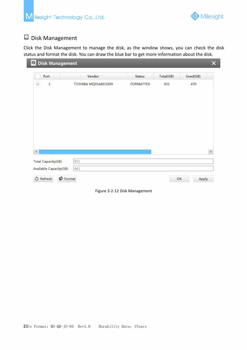
StatusStatus includes Device Information, Network Status, Camera Status, Event Status and Disk Status.Status adopts the page form to display the contents.
[Device Information]From this page, you can check the Device ID, Device Name, Camera Number(The maximumnumber of camera can be added to the NVR), HDD number(The maximum number of HDD can besupported to the NVR), Alarm Input Number, Alarm Output Number, Device Serial Number,Firmware Version, Hardware Version and Uptime.
File Format:MS-QR-JS-04 Rev1.0 Durability Date:1Years30
Figure 3-2-21 Device Information
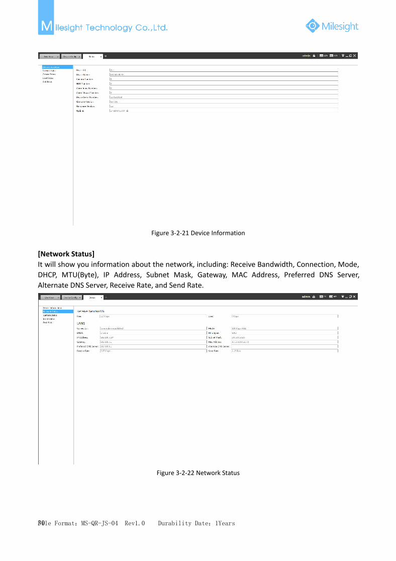
[Network Status]It will show you information about the network, including: Receive Bandwidth, Connection, Mode,DHCP, MTU(Byte), IP Address, Subnet Mask, Gateway, MAC Address, Preferred DNS Server,Alternate DNS Server, Receive Rate, and Send Rate.
Figure 3-2-22 Network Status

File Format:MS-QR-JS-04 Rev1.0 Durability Date:1Years31
[Camera Status]It will show you the Channel, Name, Enable or not, IP address, Record or not, Frame Rate, Bitrate,Resolution of main stream, Status of connection.
Figure 3-2-23 Camera Status
[Event Status]The icon will turn to red when the device is in the event status:
Figure 3-2-24 Event Status

File Format:MS-QR-JS-04 Rev1.0 Durability Date:1Years32
[Disk Status]It will show you the Disk port, Vendor, Status, Total capability, Used capability, Free capability HDDtype, In use or not and Recycle Mode on or off.
Figure 3-2-25 Disk Status
Maintenance
Click the Maintenance button , a window will pop up as follows, you can choose the log and
photo retention period for 1/2/4/6/8/10/12 months or permanent in Auto Maintenance part. And
for the System Management part, you can click the Reboot button to reboot the CMS.
Figure 3-2-26 Maintenance

File Format:MS-QR-JS-04 Rev1.0 Durability Date:1Years33
3.2.2 Camera
The Device Configuration for Network Camera is as follows:
Figure 3-2-27 Camera
3.2.2.1 Video
VideoThe Video page is as follows:
Figure 3-2-28 Video

File Format:MS-QR-JS-04 Rev1.0 Durability Date:1Years34
The meanings of the items on Video page can be referred to the table below:
Table 3-2-5 Video
Parameters Function Introduction
Video Codec H.265/H.264/MJPEG available
Frame SizeOptions include 4M(2592*1520),3M(2048* 1536), 1080P(1920*1080),2M(1600 *1200), 1.3M(1280*960), 720P(1280*720), D1 (704*576)
Maximum Frame Rate Maximum refresh frame rate per second
Bit RateTransmitting bits of data per second, this item is optional only if you selectthe H.264
Bit Rate ControlCBR: Constant Bitrate. The rate of CBR output is constant
VBR: Variable Bitrate. The rate of VBR output will be variable according to the
ProfileThe option is for H.264. Base/Main/High can be selected according to yourneeds
I-frame IntervalSet the I-frame interval to 1~120, this item is optional only if you selected theH.264
ImageThe Image page is as follows:
Figure 3-2-29 Image

File Format:MS-QR-JS-04 Rev1.0 Durability Date:1Years35
The meanings of the items on Image page can be referred to the table below:Table 3-2-6 Image
Parameters Function IntroductionVideo Stream Choose the stream which you want to edit
Show Video Title Check the checkbox to show video title
Video Title You can customize the video title
Text Position OSD position on the image
Display Date Check the checkbox to display date on the image
Date Position Date display position on the image
Date Format The format of date
Wide Dynamic RangeThis function enables the capture and display of both bright and dark areasdetails in the same frame.
Power Line Frequency 60HZ flicker for NTSC mode and 50HZ flicker for PAL mode
Day/Night Mode
There are several parameters such as Exposure Level, Maximum ExposureTime and IR-CUT Interval, etc. associated with this modeNight Mode: To switch camera live view image to Night modeDay Mode: To switch camera live view image to Day modeAuto Mode: To enable live view image changing Day or Night modeautomatically based on the environment lightCustomize: To customize the settings of switching Day and Night Mode
Start/End time of night Choose the start and the end of night time
Video Orientation
There are four options available, you can select one to meet your needNormal: Remain the image in normal directionFlip Horizontal: Flip the image horizontallyFlip vertical: Flip the image verticallyRotating 90°: The images is presented rotating 90°Rotating 180°: The images is presented upside downRotating 270°: The images is presented rotating 270°
Privacy MaskMilesight CMS supports privacy mask. The setting steps are as follows:Step1: Check the checkbox to enable the Privacy Mask function;Step2: Choose the mask type
Step3: Hold down the mouse to draw the area and click button to apply settings;
Step4: Click the button to clear all drawn area;

File Format:MS-QR-JS-04 Rev1.0 Durability Date:1Years36
Figure 3-2-30 Privacy Mask
AudioThis audio function allows you to hear the sound from the camera or transmit your sound to thecamera side. A two-way communication is also possible to be achieved with this feature. Alarmcan be triggered when the audio input is above a certain alarm level you set, and configured audiocan be played when an alarm occurs.
Figure 3-2-31 Audio
File Format:MS-QR-JS-04 Rev1.0 Durability Date:1Years37
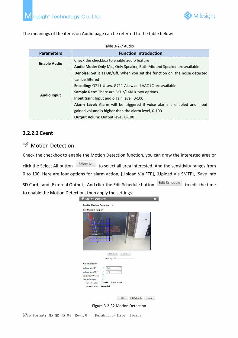
The meanings of the items on Audio page can be referred to the table below:
Table 3-2-7 Audio
Parameters Function Introduction
Enable AudioCheck the checkbox to enable audio featureAudio Mode: Only Mic, Only Speaker, Both Mic and Speaker are available
Audio Input
Denoise: Set it as On/Off. When you set the function on, the noise detectedcan be filteredEncoding: G711-ULaw, G711-ALaw and AAC LC are availableSample Rate: There are 8KHz/16KHz two optionsInput Gain: Input audio gain level, 0-100Alarm Level: Alarm will be triggered if voice alarm is enabled and inputgained volume is higher than the alarm level, 0-100Output Volum: Output level, 0-100
3.2.2.2 Event
Motion DetectionCheck the checkbox to enable the Motion Detection function, you can draw the interested area or
click the Select All button to select all area interested. And the sensitivity ranges from
0 to 100. Here are four options for alarm action, [Upload Via FTP], [Upload Via SMTP], [Save Into
SD Card], and [External Output]. And click the Edit Schedule button to edit the time
to enable the Motion Detection, then apply the settings.
Figure 3-2-32 Motion Detection

File Format:MS-QR-JS-04 Rev1.0 Durability Date:1Years38
Alarm I/OEnable the function first before you using it. CMS supports several alarm actions when alarm hasbeen triggered. Do not forget setting FTP and SMTP before enabling the alarm function.
Figure 3-2-33 Alarm I/O
Audio AlarmAudio function should be enabled before enabling Audio Alarm. CMS supports several alarmactions when alarm has been triggered. Do not forget setting FTP and SMTP before enabling thealarm function.

File Format:MS-QR-JS-04 Rev1.0 Durability Date:1Years39
Figure 3-2-34 Audio Alarm
ExceptionThere are two Alarm Types in Exception: Network Lost and IP Conflict. See Figure 3-2-35:
Figure 3-2-35 Exception
Note Please finish the relevant settings in the Network part before using the the Alarm function on CMS; It will activate the alarm when the current status is different from normal status on Alarm I/O page, you can
set the status by yourself;
3.2.2.3 Record
RecordCMS supports to record video in SD card of camera or NAS. You can set the record file size from10M to 256M, select the record frame type for All or Key and set the time to record. The Recordpage is as follows:
Figure 3-2-36 Record

File Format:MS-QR-JS-04 Rev1.0 Durability Date:1Years40
3.2.2.4 System
Date&TimeYou can select the time zone and decide whether to enable the Daylight Saving Time or not. It alsosupports to sync date and time with NTP or set the time manually. After finishing the settings,
click the Apply button to save and apply the settings to the CMS.
Figure 3-2-37 Date&Time
Network[Network]The Network page is as follows:
Figure 3-2-38 Network

File Format:MS-QR-JS-04 Rev1.0 Durability Date:1Years41
[SMTP]Alarm video files will be sent to specific mail account through SMTP server. Please make sure thatthe SMTP settings were correctly set before using it.
Figure 3-2-39 SMTP
The meanings of the items on SMTP page can be referred to the table below:
Table 3-2-8 SMTP
Parameters Function Introduction
User Name The sender's name. It is usually the same as the account name
Sender Email address to send video files attached to emails
Password The password of the sender
Server The SMTP server IP address or host name(e.g.smtp.gmail.com)
PortThe port of SMTP server. The default TCP/IP port for SMTP is 25(not secured).For SSL/TLS port, it depends on the mail you use
To E-mail E-mail address to receive video files
Encryption Check the checkbox to enable SSL or TLS if it is required by the SMTP server.

File Format:MS-QR-JS-04 Rev1.0 Durability Date:1Years42
[FTP]Alarm video files will be sent to specific FTP server. Please make sure that the FTP settings werecorrectly set before using it.
Figure 3-2-40 FTP
The meanings of the items on FTP page can be referred to the table below:
Table 3-2-9 FTP
Parameters Function Introduction
Server FTP server address
Server Port The port of the FTP server. Generally it is 21
User Name User name used to log in to the FTP sever
Password User password
FTP Folder Name Path where video will be uploaded to on the FTP server
[DDNS]DDNS allows you to access the camera via domain names instead of IP address. It manages tochange IP address and update your domain information dynamically. You need to register anaccount from a provider.

File Format:MS-QR-JS-04 Rev1.0 Durability Date:1Years43
Figure 3-2-41 DDNS
The meanings of the items on DDNS page can be referred to the table below:
Table 3-2-10 DDNS
Parameters Function Introduction
Enable DDNS Check the checkbox to enable DDNS service
NameSupport DDNS from now dyndns.org, freedns.afraid.org, www.no-ip.com,www.zoneedit.com and Customize
User name Account name obtained from DDNS providerPassword Account passwordHost name DDNS name enabled in the account
[Port]You can set HTTP and RTSP port here.
Figure 3-2-42 Port

File Format:MS-QR-JS-04 Rev1.0 Durability Date:1Years44
UsersThere are three levels of Users: Admin, Operator, and Viewer. Admin can not be deleted and youcan only change its password. Operator and Viewer can be added, edited or deleted.
Figure 3-2-43 Users
SystemThe System page is as follows:
Figure 3-2-44 SystemThe meanings of the items on System page can be referred to the table below:

File Format:MS-QR-JS-04 Rev1.0 Durability Date:1Years45
Table 3-2-11 System
Parameters Function Introduction
Device Name The device name can be customized. It will be seen in file names of video files
Product Model The product model of the camera
Hardware Version The hardware version of the camera
Software Version The software version of the camera can be upgraded
MAC Address Media Access Control address
Click the button to reboot the device
Click the button to reset the settings to the default one.
Click the button to import the firmware file from PC, and click the
button to upgrade.

File Format:MS-QR-JS-04 Rev1.0 Durability Date:1Years46
3.3 Users
You can add, edit and delete the Operator or Viewer account while you are only allowed to editthe password of the Admin. The Add User page is as follows:
Figure 3-3-1 User

File Format:MS-QR-JS-04 Rev1.0 Durability Date:1Years47
4.View
4.1 Live View
There are icons of PTZ, Image Configuration, View Settings, Carousel on Live View interface. LiveView interface is shown as Figure 4-1-1:
Figure 4-1-1 Live View
After adding the devices, you can drag or double click device name to view windows to displaytheir live view. 1/4/8(1+7)(4+4)/9/16/36/64 view windows can be set to meet your needs.The icons on toolbar are as follows:
Figure 4-1-2 Toolbar
The description of the icons can be referred to the table below:
Table 4-1-1 Toolbar
Item Function Introduction
Play all secondary
Stop all

File Format:MS-QR-JS-04 Rev1.0 Durability Date:1Years48
Cursor
Click the button and enable digital zoom the live view
PTZ
Image
Save View, save the current view to replace the old view
New View, create a new view
Carouse
Fullscreen
Multi screen,up to four screens
/ / 1/4/9 Windows Button
Click the button to get more options of display windows
/ [Pre Page]/[Next Page] button
4.1.1 Live view interface
DeviceDevice column in the live view shows what kind of device are connected to the CMS now:

File Format:MS-QR-JS-04 Rev1.0 Durability Date:1Years49
Figure 4-1-3 Live view deviceRight-click on devices in the column:
Rename Reset the name of the camera on the listRefresh Refresh the status of the NVRPlay Play the live view of the chosen deviceStop Stop the live view of the chosen devicePlay all Play all the live viewStop all Stop all the live viewLog out Log out of the deviceRemote Configuration Configure the cameraSynchronize Name Synchronize device name with the deviceSynchronize All Name Synchronize all name with the device
There are steps to display device under the Device mode:Step1: Make sure the device is available;Step2: Select one window to display;Step3: Right click a camera and choose [Play] to display the camera. When you choose a
NVR, there is a [Play All] to display all cameras linked with the NVR. You can alsodouble click the device or drag it into the selected window.
Table 4-1-2 Icon meanings of the device
Item Function Introduction
/ Camera/NVR, which is connected
/ Camera/NVR, which is not connected
/ Camera/NVR, which logs out
List Button, click the button to list all cameras linked with the NVR

File Format:MS-QR-JS-04 Rev1.0 Durability Date:1Years50
ViewRight-click on View:
Play View Play the ViewDelete View Delete the ViewRename View Rename the ViewSave Save the current view to replace the old oneSave as Save the current view into a new View
View helps you watch and manage the live view more efficiently. By set Views, you can save timeto manage the Live View:
Step1: Click the New View button to create a new View;
Step2: Display the cameras according to Device Part;
Step3: Click the Save View button to save the live view. You can right-click the View and
choose the [Play View].
Note Double clicking a NVR will lead to display all the cameras linked with the NVR; Once a window is selected, it’s border color will turn into white;
4.1.2 Settings of Display the Live View
The toolbar of the Live View window:
Start/Stop recording
Snapshot
Full screen
Stop the live view
Click the Menu button →[Configuration] to set the path to save the Record and Snapshot files,
and the files will be sorted by date.

File Format:MS-QR-JS-04 Rev1.0 Durability Date:1Years51
Figure 4-1-4 System Config
Right-click the live view window, the interface is as follows:Stop Stop playing the live view16:9 Ratio of length to width is 16:94:3 Ratio of length to width is 4:3Window Size Suit the size to the windowsStream Type Three stream types are availablePrevious Screen Turn to the previous screenNext Screen Turn to the next screenFull Screen Display windows in full screen
PTZ
Click the PTZ button , there will be a same button in the bottom-left corner of the selected
window. Click the button in the window, the PTZ function interface will appear. The interface is asfollows:
Figure 4-1-5 PTZ

File Format:MS-QR-JS-04 Rev1.0 Durability Date:1Years52
The meanings of the items can be referred to the table below:Table 4-1-3 PTZ
Item Function Introduction
You can adjust the direction of PTZ network camera according to thebuttons on the icon
You can draw the progress bar to set the level of zoom in or zoom out
Focus
Iris
/ Focus far/near or Iris adjustment
You can draw the progress bar to set the speed of PTZ action
Preset position, you can add 10 preset positions to Live View interface
Click this button to set preset position
Delete the present preset position
Call the present preset position
Image
Click the Image button , there will be a same button in the bottom-left corner of the selected
window. Click the button in the window, the Image function interface will appear. The interface isas follows:
Figure 4-1-6 Image

File Format:MS-QR-JS-04 Rev1.0 Durability Date:1Years53
The meanings of the items can be referred to the table below:Table 4-1-4 Image
Item Function Introduction
Brightness
Contrast
Saturation
Sharpness
Noise Reduction

File Format:MS-QR-JS-04 Rev1.0 Durability Date:1Years54
4.2 Playback
CMS supports playback. It can play recorded files on devices, the Playback page is as follows:
Figure 4-2-1 Playback
You can refer to the steps as follows to playback the recorded files:Step1: Select the desired devices by checking the checkbox of the devices; the NVR has List button
to list the added cameras;Step2: Choose the date of which typeface is blue(blue means there are record files, black meansno file and red means weekend), the background will turn to blue once the date is selected; then
click the Search button to find the recorded files;
Step3: Check the time line to select the time to playback; there are four colors represent different
record files; click the button to get the previous/next page of channels; put the
mouse on the time line and scroll up or down to zoom in/out the time;Step4:Window border will turn into white once the window has been selected; the first window is
the default window;Step5: Click the Play button to playback; Speed Down, Speed Up and Single Step are available;Step6: Select the NVR, choose cameras playback -> left-click the mouse on the selected time line
-> click the Cut button -> left-click again in different place then you can cut a part of
the playback file -> click Download button to back up the NVR playback files;
Right-click the window during playback, it will pop up the interface as follows:
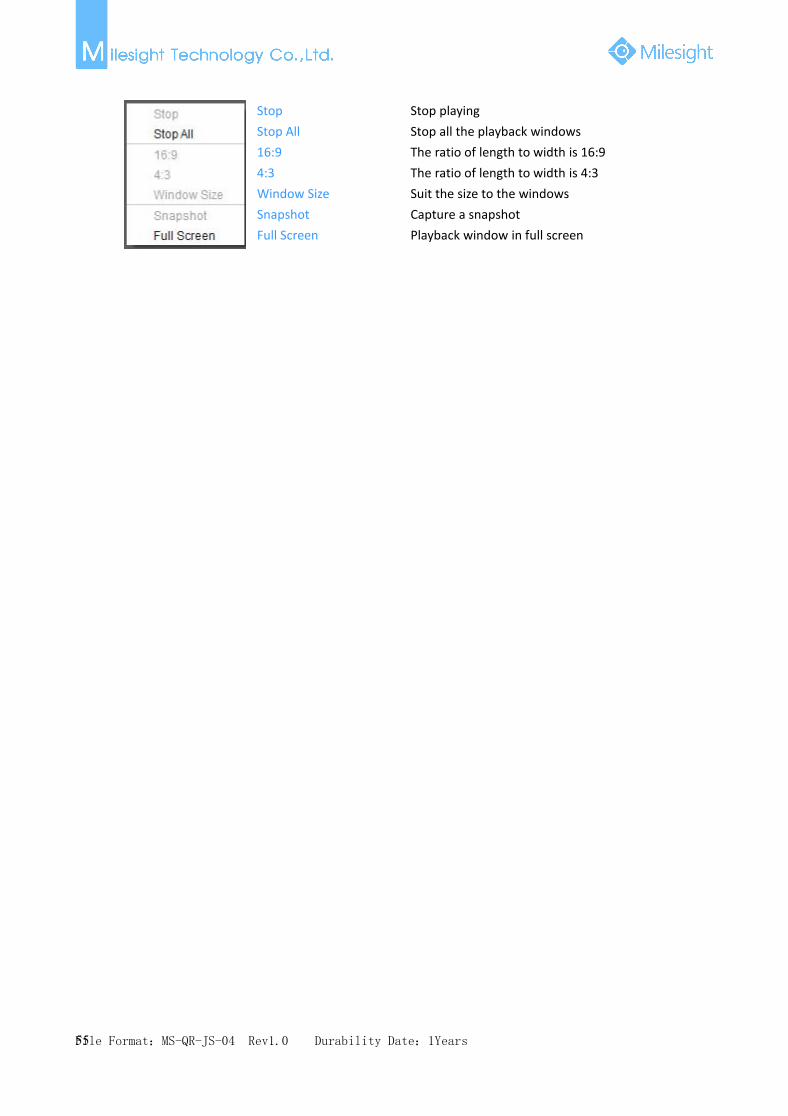
File Format:MS-QR-JS-04 Rev1.0 Durability Date:1Years55
Stop Stop playingStop All Stop all the playback windows16:9 The ratio of length to width is 16:94:3 The ratio of length to width is 4:3Window Size Suit the size to the windowsSnapshot Capture a snapshotFull Screen Playback window in full screen
File Format:MS-QR-JS-04 Rev1.0 Durability Date:1Years56
5.Tools
5.1 E-Map
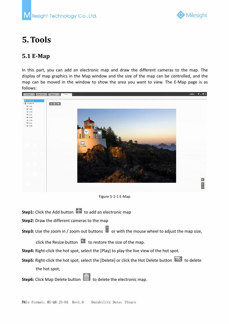
In this part, you can add an electronic map and draw the different cameras to the map. Thedisplay of map graphics in the Map window and the size of the map can be controlled, and themap can be moved in the window to show the area you want to view. The E-Map page is asfollows:
Figure 5-1-1 E-Map
Step1: Click the Add button to add an electronic map
Step2: Draw the different cameras to the map
Step3: Use the zoom in / zoom out buttons or with the mouse wheel to adjust the map size,
click the Resize button to restore the size of the map.
Step4: Right-click the hot spot, select the [Play] to play the live view of the hot spot.
Step5: Right-click the hot spot, select the [Delete] or click the Hot Delete button to delete
the hot spot;
Step6: Click Map Delete button to delete the electronic map.

File Format:MS-QR-JS-04 Rev1.0 Durability Date:1Years57
5.2 Logs
The logs contain the information about the time and IP that has accessed the camera through web.The Logs page is as follows:
Figure 5-2-1 Logs
The meanings of the items can be referred to the table below:
Table 5-2-1 Log
Parameters Function Introduction
Main Type There are three main log types: [All], [System Log], [Operation Log]
Sub TypeOn the premise of main type has been selected, select the sub type to narrowthe range of logs
Start Time The time log starts
End Time The time log ends
Click the button to search the matched logs
Export the log file
You can click the bar to list the log by items such as Log ID, Time, User, Main Type, Sub Type,Device Name, Device Type,etc.

File Format:MS-QR-JS-04 Rev1.0 Durability Date:1Years58
6. Service
6.1 Service
Milesight Technology Co., Ltd provides customers with timely and comprehensive technicalsupport services. End-users can contact your local dealer to obtain technical support. Distributorsand resellers can contact directly with Milesight for technical support.Technical Support Mailbox: [email protected]: http://www.milesight.comOnline Problem Submission System: http://www.milesight.com/service/feedback.aspAddress: No.23Wanghai Road,2nd Software Park, Xiamen,ChinaZip Code: 361006TEL: +86-592-5922772FAX: +86-592-5922775
MilesightMore in Sight