Embed Size (px)
Citation preview

SC-BEN092751 | TBE-SC-ALL | Version 5.1 EN
Central inverterSUNNY CENTRAL User Manual


SMA Solar Technology AG Table of Contents
User Manual SC-BEN092751 3
Table of Contents1 Notes on this Manual. . . . . . . . . . . . . . . . . . . . . . . . . . . . . . 51.1 Symbols Used . . . . . . . . . . . . . . . . . . . . . . . . . . . . . . . . . . . . . . . 51.2 Target Group . . . . . . . . . . . . . . . . . . . . . . . . . . . . . . . . . . . . . . . 61.3 Applicability . . . . . . . . . . . . . . . . . . . . . . . . . . . . . . . . . . . . . . . . 61.4 Documentation . . . . . . . . . . . . . . . . . . . . . . . . . . . . . . . . . . . . . . 62 Safety Instructions . . . . . . . . . . . . . . . . . . . . . . . . . . . . . . . . 73 Description of the Sunny Central . . . . . . . . . . . . . . . . . . . . 93.1 Identifying the Sunny Central . . . . . . . . . . . . . . . . . . . . . . . . . . 103.2 The Sunny Central’s Control Elements . . . . . . . . . . . . . . . . . . . 113.2.1 Sunny Central Control. . . . . . . . . . . . . . . . . . . . . . . . . . . . . . . . . . . . . . . . . . 113.2.2 Light Indicators . . . . . . . . . . . . . . . . . . . . . . . . . . . . . . . . . . . . . . . . . . . . . . . 123.2.3 Start-up Key Switch . . . . . . . . . . . . . . . . . . . . . . . . . . . . . . . . . . . . . . . . . . . . 123.2.4 Emergency Shut-off . . . . . . . . . . . . . . . . . . . . . . . . . . . . . . . . . . . . . . . . . . . . 123.2.5 AC Switch . . . . . . . . . . . . . . . . . . . . . . . . . . . . . . . . . . . . . . . . . . . . . . . . . . . 133.3 Operating Modes. . . . . . . . . . . . . . . . . . . . . . . . . . . . . . . . . . . 143.3.1 Operating Modes of the Sunny Central . . . . . . . . . . . . . . . . . . . . . . . . . . . . 143.3.2 Operating Modes of Team Systems . . . . . . . . . . . . . . . . . . . . . . . . . . . . . . . 16
4 Sunny Central Control Operation. . . . . . . . . . . . . . . . . . . 184.1 Functions of the Control Buttons . . . . . . . . . . . . . . . . . . . . . . . . 194.2 Explanation of the Display Symbols . . . . . . . . . . . . . . . . . . . . . 204.3 Adjusting the Display Contrast . . . . . . . . . . . . . . . . . . . . . . . . . 204.4 Adjusting Parameters and Settings . . . . . . . . . . . . . . . . . . . . . . 205 Sunny Central Control Menu. . . . . . . . . . . . . . . . . . . . . . . 215.1 Overview of the Menu . . . . . . . . . . . . . . . . . . . . . . . . . . . . . . . 225.2 Setting the Language . . . . . . . . . . . . . . . . . . . . . . . . . . . . . . . . 235.3 Changing the Date and Time . . . . . . . . . . . . . . . . . . . . . . . . . . 24

Table of Contents SMA Solar Technology AG
4 SC-BEN092751 User Manual
5.4 Entering the Password. . . . . . . . . . . . . . . . . . . . . . . . . . . . . . . . 266 Parameters . . . . . . . . . . . . . . . . . . . . . . . . . . . . . . . . . . . . . 286.1 Description of the Parameter Functions . . . . . . . . . . . . . . . . . . . 296.2 Default Parameter Settings . . . . . . . . . . . . . . . . . . . . . . . . . . . . 316.3 Adjusting Parameters . . . . . . . . . . . . . . . . . . . . . . . . . . . . . . . . 327 Communication. . . . . . . . . . . . . . . . . . . . . . . . . . . . . . . . . . 347.1 Remote-Info . . . . . . . . . . . . . . . . . . . . . . . . . . . . . . . . . . . . . . . . 347.2 Activating E-mail Reports. . . . . . . . . . . . . . . . . . . . . . . . . . . . . . 367.3 Entering or Changing E-Mail Addresses . . . . . . . . . . . . . . . . . . 367.4 Selecting the Report Types to Send . . . . . . . . . . . . . . . . . . . . . 377.5 Sending a Test Report . . . . . . . . . . . . . . . . . . . . . . . . . . . . . . . . 398 External Sensors. . . . . . . . . . . . . . . . . . . . . . . . . . . . . . . . . 408.1 Configuring the External Sensors . . . . . . . . . . . . . . . . . . . . . . . 408.2 Calculating Gain and Offset. . . . . . . . . . . . . . . . . . . . . . . . . . . 439 Failures and Warnings . . . . . . . . . . . . . . . . . . . . . . . . . . . 459.1 Fault Diagnosis . . . . . . . . . . . . . . . . . . . . . . . . . . . . . . . . . . . . . 459.1.1 Categories of Failures and Warnings . . . . . . . . . . . . . . . . . . . . . . . . . . . . . . 459.1.2 Types of Failures and Warnings . . . . . . . . . . . . . . . . . . . . . . . . . . . . . . . . . . 469.1.3 Warnings . . . . . . . . . . . . . . . . . . . . . . . . . . . . . . . . . . . . . . . . . . . . . . . . . . . 479.1.4 Failures . . . . . . . . . . . . . . . . . . . . . . . . . . . . . . . . . . . . . . . . . . . . . . . . . . . . . 519.2 Confirming Errors at the Sunny Central Control . . . . . . . . . . . . 5810 Maintenance. . . . . . . . . . . . . . . . . . . . . . . . . . . . . . . . . . . . 6011 Contact . . . . . . . . . . . . . . . . . . . . . . . . . . . . . . . . . . . . . . . . 63
SMA Solar Technology AG Notes on this Manual
User Manual SC-BEN092751 5
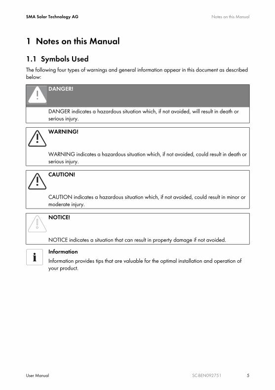
1 Notes on this Manual1.1 Symbols UsedThe following four types of warnings and general information appear in this document as described below:
DANGER!
DANGER indicates a hazardous situation which, if not avoided, will result in death or serious injury.
WARNING!
WARNING indicates a hazardous situation which, if not avoided, could result in death or serious injury.
CAUTION!
CAUTION indicates a hazardous situation which, if not avoided, could result in minor or moderate injury.
NOTICE!
NOTICE indicates a situation that can result in property damage if not avoided.InformationInformation provides tips that are valuable for the optimal installation and operation of your product.

Notes on this Manual SMA Solar Technology AG
6 SC-BEN092751 User Manual
1.2 Target GroupThis documentation is intended for Sunny Central installers and operators. It includes a description of how to operate the Sunny Central Control, maintenance of the Sunny Central, and troubleshooting with the aid of the Sunny Central Control.
1.3 ApplicabilityThis documentation describes how to operate the Sunny Central indoor and outdoor central inverters. It applies for software versions 6.07 and 6.08.
1.4 DocumentationThe following list shows the documents which you receive with your Sunny Central, and the information which each respective document contains:
• Installation guide: setup and installation of the Sunny Central• User manual: how to operate the Sunny Central and Sunny Central Control• Wiring diagrams: the Sunny Central's wiring diagrams• Technical data sheets: technical data pertaining to the Sunny Central

SMA Solar Technology AG Safety Instructions
User Manual SC-BEN092751 7
2 Safety InstructionsDANGER!Risk of lethal electric shock!
Death resulting from burning and electric shock upon touching the medium-voltage grid's live components.
• Do not touch the live components of the Sunny Central or medium-voltage grid.• Observe all safety regulations which apply to activity that involves the medium-
voltage grid.
WARNING!Risk of lethal electric shock!
High voltages are present in the device.• All work on the Sunny Central must be carried out by a trained and qualified
electrician!• Work on the Sunny Central is only to be performed as described in the following
sections!• Observe all safety instructions listed!• Follow all safety instructions included in the Sunny Central's installation guide!
WARNING!Lethal danger caused by damage to the Sunny Central!
Damage to the Sunny Central, e.g. defective cables, or a damaged housing, can lead to death by electric shock or fire!
• Only use the Sunny Central when it is safe to do so!• Only use the Sunny Central if no damage is visibly evident!• Visually check the Sunny Central for damage on a regular basis!• Ensure that all external safety features are freely accessible at all times, and that they
are regularly tested for correct functionality!

Safety Instructions SMA Solar Technology AG
8 SC-BEN092751 User Manual
NOTICE!Possible damage to the Sunny Central!
The Sunny Central can be damaged irreparably by electrostatic discharge at its components.
• When working on the Sunny Central, and handling the module assemblies, remember to observe all ESD safety regulations!
• Discharge any electrostatic charge by touching the grounded Sunny Central housing• before handling electronic components!
Storage of handbooksThis user manual, the installation guide, the data sheets, the operating manuals of installed components, and the wiring diagrams must be kept in the immediate vicinity of the Sunny Central. They must be available to operators and maintenance staff at all times.

SMA Solar Technology AG Description of the Sunny Central
User Manual SC-BEN092751 9
3 Description of the Sunny CentralThe Sunny Central is a solar inverter. It allows photovoltaic solar energy from solar modules to be converted and fed into a low-voltage or medium-voltage grid.Principle of a grid-connected solar power system with a Sunny Central
Sunny CentralThe standard Sunny Central is equipped with a low-voltage transformer, and feeds into the low-voltage grid.Sunny Central HEThe Sunny Central HE is a high efficiency photovoltaic inverter. It does not have its own low-voltage transformer. The Sunny Central HE requires an adapted external medium-voltage transformer via which it can feed into the grid.Sunny Central MVThe MV stations are medium-voltage stations. In an MV station, two Sunny Central HE devices feed into a shared medium-voltage transformer. The Sunny Central MV feeds into the medium-voltage grid.
SMA
Solar modules
Sunny Central
Public grid

Description of the Sunny Central SMA Solar Technology AG
10 SC-BEN092751 User Manual
3.1 Identifying the Sunny CentralYou can identify the Sunny Central using the name plate (see figure below). The name plate is located on the inside of the Sunny Central's door.
A The Sunny Central's type name with option code (optional).B The version of the Sunny Central; "s" means special version.C Serial number of the Sunny Central.
SMA Technologie AGHannoversche Str. 1-5, 34266 Niestetal, Germany
Tel: +49 561 9522-0 Fax: +49 561 9522-100
Typ: SC-100: 010.322.03Version:Serial No.:Year of manufacture:AC-Voltage/-current:Max. DC-Voltage/current:EVR (Option):Auxiliary Voltage:Testing Voltage:Weight:
Es100
02/2007400V,50Hz/261A
900V/354A1000V/354A
AC230V, 50Hz/DC24V1,7kV/2,6 (2,8)kV DC
1450kg
made in germany www.sma.de
A
BC
SMA Solar Technology AG Description of the Sunny Central
User Manual SC-BEN092751 11
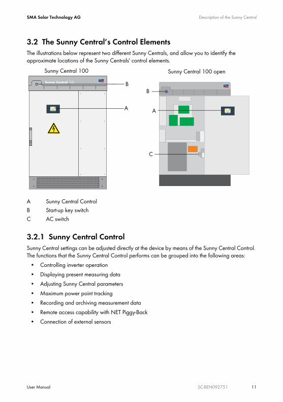
3.2 The Sunny Central’s Control ElementsThe illustrations below represent two different Sunny Centrals, and allow you to identify the approximate locations of the Sunny Centrals' control elements.
3.2.1 Sunny Central ControlSunny Central settings can be adjusted directly at the device by means of the Sunny Central Control. The functions that the Sunny Central Control performs can be grouped into the following areas:
• Controlling inverter operation• Displaying present measuring data• Adjusting Sunny Central parameters• Maximum power point tracking• Recording and archiving measurement data• Remote access capability with NET Piggy-Back• Connection of external sensors
A Sunny Central ControlB Start-up key switchC AC switch
Sunny Central 100SMA
SMA
SMA
SMA
Sunny Central 100 Sunny Central 100 open
A
B
A
C
B

Description of the Sunny Central SMA Solar Technology AG
12 SC-BEN092751 User Manual
3.2.2 Light IndicatorsThree light indicators are situated on the front of the Sunny Central. If an error occurs, the type of disturbance is shown by these light indicators.
3.2.3 Start-up Key SwitchThe start-up key switch activates or deactivates the Sunny Central. When this switch is turned to the "Start" position, the Sunny Central changes from "Stop" mode to "Wait" mode. If there is sufficient radiation, the Sunny Central changes to the "Startup" mode, and subsequently begins grid feeding. If the radiation, and thus the input voltage, is too low, the Sunny Central remains in "Wait" mode.If the start-up key switch is turned to the "Stop" position, the DC switch is deactivated automatically by a motor drive.
3.2.4 Emergency Shut-off
The emergency shut-off switch immediately disconnects the Sunny Central from the grid, and from the solar generator, placing the Sunny Central in a safe condition.When the emergency shut-off switch is pressed, it locks in the "Off" position. The emergency shut-off switch can only be unlocked using its key. It is also necessary to reset the emergency shut-off operation with the Sunny Central Control or with Sunny Data Control.The Sunny Central 100 indoor and the Sunny Central 100 outdoor have no emergency shut-off switch. You have the option of installing an external emergency shut-off switch at the Sunny Central.You can also install an external emergency shut-off switch at the other Sunny Centrals, or deactivate several Sunny Centrals with a shared emergency shut-off switch.
• Yellow: The Sunny Central is in "Alert" mode. The Sunny Central does not switch itself off. Once the error is no longer present, the error message is reset automatically. Check the system.
• White: The Sunny Centrals are operating in Team mode. The Team contactor is activated.• Red: The Sunny Central is in "Failure" mode. If the Sunny Central has detected a failure,
it shuts down. Once the fault has been removed and confirmed, it resumes operation. For more information, see section 9.1.2 "Types of Failures and Warnings" (page 46).
NOTICE!Improper use of the emergency shut-off switch causes damage to the Sunny Central!The Sunny Central's components are subjected to considerable stress if the emergency shut-off switch is used under load. This can irreparably damage individual components.
• Only use the emergency shut-off switch in an emergency.• To switch off the Sunny Central, use the start-up key switch.

SMA Solar Technology AG Description of the Sunny Central
User Manual SC-BEN092751 13
3.2.5 AC Switch
Upon use of the AC switch, the Sunny Central is disconnected from the grid on the AC side.
NOTICE!Improper use of the AC switch may cause damage to the Sunny Central!
The Sunny Central's components are subjected to considerable stress if the AC switch is used under load. This can irreparably damage individual components.
• Only use the AC switch if the Sunny Central has been set to "Stop" by turning the start-up key switch.

Description of the Sunny Central SMA Solar Technology AG
14 SC-BEN092751 User Manual
3.3 Operating Modes
3.3.1 Operating Modes of the Sunny CentralWhen activated, the Sunny Central passes through different modes as pictured below. When deactivated, the Sunny Central resides in the operating mode "Stop". If the key switch is turned, the Sunny Central changes to the "Wait" mode. Failure
No failure
Stop
"Start" switch
"Stop" "Stop"
FailureShutdown FailureWait
Startup MPP load operation
Start-up finished Failure
Vpv > UpvStart und T > Tstart
Ppv < PpvStopand T > Tstop
orswitch "Stop"
Failure

SMA Solar Technology AG Description of the Sunny Central
User Manual SC-BEN092751 15
StopThe Sunny Central is deactivated. The Sunny Central remains in this mode until the start-up key switch is turned to the start position.WaitIf the input voltage is below the defined start voltage "UpvStart", the Sunny Central resides in "Wait" mode. The value of the UpvStart setting is shown in the Sunny Central Control's display.StartupIf the input voltage is above the start voltage "UpvStart", the Sunny Central waits until the time defined by the parameter "Tstart" has passed. If the input voltage has not fallen below the start voltage "UpvStart" during this period, the Sunny Central starts up. The AC contactor is closed and the Sunny Central is isolated. Once the Sunny Central is ready for operation, it begins grid feeding.
MPP Load OperationAfter successful activation, the Sunny Central seeks the solar generator's maximum power point (MPP), and begins feeding into the grid. ShutdownThe Sunny Central shuts down if:
• the power measured during the interval "Tstop" is less than "PpvStop",• a failure occurs which requires a shutdown of the Sunny Central, or• the start-up key switch is set to "Stop".
FailuresIf a failure occurs during operation, the Sunny Central shuts down and the failure is shown as a disturbance in the Sunny Central Control's display. Refer to section 9 "Failures and Warnings" (page 45) for a list of disturbances.
Start Voltage UpvStartThe start voltage UpvStart must be adjusted for the solar generator which is connected to the Sunny Central.

Description of the Sunny Central SMA Solar Technology AG
16 SC-BEN092751 User Manual
3.3.2 Operating Modes of Team SystemsIn addition to the normal operating modes, Sunny Centrals which are configured as a Team system also have Team operating modes.StopIf one of the two Sunny Centrals is deactivated, the second Sunny Central is operated individually without Team. If only the Team leader is operating, it is in the "Startup" mode. If only the Team member is operating, it resides in the "String Operation" mode.Linking (Mornings)The Team contactor is disconnected. If the input voltage (Vpv) of both Sunny Centrals is greater than the PV start voltage (UpvStart) - 50 V, the Team contactor closes itself. The Team leader begins to operate as soon as the start conditions are fulfilled. The Team leader goes into the "Team leader" mode and feeds the power into the grid. The Team member changes to the "PV linked" mode. The Team leader and the Team member operate as a Team.DisconnectingThe Team member is in "Team mode". The Team leader is in "Team leader" mode. Both Sunny Centrals are feeding into the grid.If the Team leader's output exceeds the value of "P-NextTeam" (default setting: 80 %), the DC contactor is switched off. Both Sunny Centrals then operate individually, and feed into the grid.Linking (Evenings)If the Team leader's AC output falls below the value of "P-PrevTeam" (default setting: 20 %), the Team contactor is switched on. The Team leader feeds the entire system power into the grid, and is in the "Team leader" mode. The Team member is in "PV linked" mode. Night OperationIf the Team leader's open circuit voltage is below UpvMin - 100 V for 30 minutes, the Team contactor is disconnected. The Team leader changes to "Startup" mode. The Team member changes to "Team mode".

SMA Solar Technology AG Description of the Sunny Central
User Manual SC-BEN092751 17
FailuresIf, when in Team mode, a failure occurs, the Team mode is immediately interrupted, and the Team contactor is disconnected. The Sunny Centrals continue to operate individually until the failure is rectified.If a failure is present for more than 60 minutes, Team mode can be resumed. For Team mode to be possible while a failure is present at a Sunny Central, the following conditions must be fulfilled:
• The communication between the two Sunny Centrals must be functioning.• The DC contactor must be functioning.• The start-up key switch must be set to the "Start" position.• None of the following failures must be present:
– Failure 201: Ground Fault 2 or plant temp. too high– Failure 206: Emergency shutdown activated
If these conditions are fulfilled, the Sunny Central at which no failure is present takes over the output of both solar generators.

Sunny Central Control Operation SMA Solar Technology AG
18 SC-BEN092751 User Manual
4 Sunny Central Control OperationThe control panel Sunny Central Control is mounted in or on the Sunny Central at eye level. The Sunny Central Control is operated by means of the four buttons below the four-line display.
Operating the Sunny Central Control with SC 100 Indoor and SC 100 Outdoor InvertersWith the Sunny Central SC 100 indoor and SC 100 outdoor inverters, the Sunny Central Control is situated inside the inverter. The Sunny Central Control may only be used in "Stop" mode with these devices.Open the Sunny Central as described in the installation guide.
Sunny Central 100SMA
SMASMA
SMA
SMA
Sunny Central Control panel
4-line display
Control buttons

SMA Solar Technology AG Sunny Central Control Operation
User Manual SC-BEN092751 19
4.1 Functions of the Control ButtonsThe four control buttons are situated below the Sunny Central Control's display.
The control buttons have several functions. In the following table, the buttons' functions are explained.
Button Meaning and function[ESC] • cancels / ends the present function
• answers questions with "No"• returns to the previous menu• changes from the online info display to the main menu
[ ↑ ] • moves up to the previous line• increases the present value
[ ↓ ] • moves down to the next line• decreases the present value
[ENTER] • selects a function from the menu• selects a value• confirms changes• answers questions with "Yes"
[ ↑ ] + [ ↓ ] • returns to the online info display
SMA
ENTER
Downward arrowUpward arrow
ESC

Sunny Central Control Operation SMA Solar Technology AG
20 SC-BEN092751 User Manual
4.2 Explanation of the Display SymbolsThe Sunny Central Control display has four lines. It uses various display symbols, which are explained in the following table.
4.3 Adjusting the Display ContrastYou can adjust the display contrast in any menu. You must press a combination of two buttons in order to increase or decrease the contrast.
4.4 Adjusting Parameters and SettingsYou can adjust the Sunny Central's parameters and settings in edit mode. Only parameters which have a solid arrow to their left ( → ) can be adjusted. Press [ENTER] to access the parameter's edit mode. The parameter's value begins to flash. You can adjust the value with the two arrow buttons. Confirm the change with [ENTER], or cancel with [ESC]. If no button is pressed for 60 seconds, the change is automatically cancelled.
Symbol Meaning↑ There are more display lines above.↓ There are more display lines below.↕ There are more display lines above and below.→ Appears at the left of the presently selected line. Press [ ↑ ] or [ ↓ ] to move to
another line.→
(glows)Appears to the left of a value which can be changed.
→(flashes)
If, for example, a parameter has been changed, the arrow flashes at the left of the active line.
¿ The Sunny Central Control is loading the next menu, or saving data.
Buttons Function[ESC] + [ ↑ ] increases the display contrast[ESC] + [ ↓ ] decreases the display contrast
Password for Adjusting ParametersParameters can only be adjusted after an installer password has been entered (see section 5.4 "Entering the Password" (page 26)).

SMA Solar Technology AG Sunny Central Control Menu
User Manual SC-BEN092751 21
5 Sunny Central Control MenuThe Sunny Central Control initializes upon activation of the Sunny Central. The initialization includes a sequence of three displays. Once the Sunny Central Control has initialized, it changes to the online info display. In the online info display, your Sunny Central's measured values and spot values are displayed.
[ ↑ ], [ ↓ ] or [ENTER]
[ ↑ ], [ ↓ ] or [ENTER]
You can switch between the three online info displays with the buttons [ ↑ ], [ ↓ ] or [ENTER]. If a warning or failure is reported, the display will alternate between the present online info display and the error with the highest priority.
Status MPPPac 85.7kWE_Today 357.5kWhE_Total 2512.3kWh
Status MPPPpv 89.27kWVpv 557VIpv 160.26A
Status MPPfac 50.04HzVac 230.51VIac 124.07A

Sunny Central Control Menu SMA Solar Technology AG
22 SC-BEN092751 User Manual
5.1 Overview of the MenuThe Sunny Central Control menu is subdivided into four main menus. The four main menus and their subcategories can be seen in the table below.
Main menu 1st menu level 2nd menu levelOperating Data Faults
Plant StatusEnergy Yield E-Total, E-TodayData Files Meas. Interval, Daily Values, Meas.ChannelsOther Operating Time, Working Time, Startup counter,
Fault counter, Alert counterSpot Values PV Ppv, Vpv, Ipv
Grid Pac, fac, Iac, Vac Phase 1, Vac Phase 2, Vac Phase 3
Other Temp. SC, Temp. PT100B, R-Iso, Mppsearchcount, Team Function
Long-Term Data Meas. Chn.Energy Yield Daily ValuesPlant Status ReportsFaults
Device Set-up PasswordSystem Language, Date/Time, Inverter Type,
BF_UZWK_Norm, SC_FirmwareParameters Param.-Function, Mpp Limit. Val., Mpp Tracking,
Start requiremt, Shut-down requ., Grid Monitor., Other
INTERFACES Communication, Analog In, Digital In, Digital OutData archives Data Recording, Meas. Interval, Max. Storage,
Chan. Select.SMUs Devices, Parameters, Measured Values, FailureNET/eMail NET, Remote-Info

SMA Solar Technology AG Sunny Central Control Menu
User Manual SC-BEN092751 23
• Operating DataThe Operating Data menu provides general information about the Sunny Central. This includes, for example, displaying energy yields, operating and feed hours, or information about the archive of stored data and any failures that are currently being reported.
• Spot ValuesThe Spot Values menu displays all available online measurement data for the system. Here, a distinction is made between the PV side, the grid side, and other measured values.
• Long-Term DataMeasurement data are saved in the Long-Term Data menu. Here, for example, you can also find a list of the failures which have occurred to date.
• Device Set-upSystem, operation, and adjustment parameters are set in the Device Set-up menu. This allows system-specific and customer-specific configuration of the Sunny Central.
5.2 Setting the LanguageThe Sunny Central Control can be operated in German, English, or Spanish. The Sunny Central's language is preset to the language specified when you placed your order. If you wish to change the language, proceed as follows:1. In the online info display, press [ESC].
2. Navigate to the "Device Set-up“ menu with the [ ↓ ] arrow button, and select it by pressing [ENTER].
[ESC]
Status MPPPac 85.7kWE_Today 357.5kWhE_Total 2512.3kWh
3 x [ ↓ ]
[ENTER]
[ Main Menu ] Operating Data Spot Values Long-Term Data → Device Set-up
Sunny Central Control Menu SMA Solar Technology AG
24 SC-BEN092751 User Manual
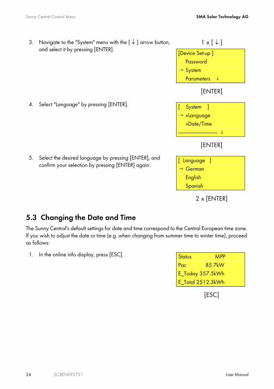
5.3 Changing the Date and TimeThe Sunny Central's default settings for date and time correspond to the Central European time zone. If you wish to adjust the date or time (e.g. when changing from summer time to winter time), proceed as follows:
3. Navigate to the "System" menu with the [ ↓ ] arrow button, and select it by pressing [ENTER].
4. Select "Language" by pressing [ENTER].
5. Select the desired language by pressing [ENTER], and confirm your selection by pressing [ENTER] again.
1. In the online info display, press [ESC].
1 x [ ↓ ]
[ENTER]
[Device Set-up ] Password→ System Parameters ↓
[ENTER]
[ System ]→ »Language »Date/Time------------------------------------- ↓
2 x [ENTER]
[ Language ]→ German English Spanish
[ESC]
Status MPPPac 85.7kWE_Today 357.5kWhE_Total 2512.3kWh

SMA Solar Technology AG Sunny Central Control Menu
User Manual SC-BEN092751 25
2. Navigate to the "Device Set-up“ menu with the [ ↓ ] arrow button, and select it by pressing [ENTER].
3. Navigate to the "System“ menu with the [ ↓ ] arrow button, and select it by pressing [ENTER].
4. Navigate to the "Date/Time“ menu with the [ ↓ ] arrow button, and select it by pressing [ENTER].
5. To make an adjustment, select either the date or the time by pressing [ENTER]. You can change from day to month to year, or from hour to minute, by pressing the [ENTER] button. The values can be increased or decreased with the arrow buttons.
6. Confirm your changes using [ENTER].
3 x [ ↓ ]
[ENTER]
[ Main Menu ] Operating Data Spot Values Long-Term Data → Device Set-up
1 x [ ↓ ]
[ENTER]
[Device Set-up ] Password→ System Parameters ↓
1 x [ ↓ ]
[ENTER]
[ System ] »Language→ »Date/Time----------------------------------- ↓
[ Date/Time ]→ 05/14/2007 13.47

Sunny Central Control Menu SMA Solar Technology AG
26 SC-BEN092751 User Manual
5.4 Entering the Password
Safety-relevant Sunny Central parameters can only be adjusted upon entry of a password. To enter the password, proceed as follows:
PasswordYou can obtain the password from the Sunny Central Serviceline. This can be reached on the following telephone number:+49 561 9522-299
1. In the online info display, press [ESC].
2. Navigate to the "Device Set-up“ menu with the [ ↓ ] arrow button, and select it by pressing [ENTER].
3. Select "Password" by pressing [ENTER].
4. Enter the password.5. If the correct password is entered, the Sunny Central Control
beeps three times. If the password is incorrect, the Sunny Central Control beeps once.
[ESC]
Status MPPPac 85.7kWE_Today 357.5kWhE_Total 2512.3kWh
3 x [ ↓ ]
[ENTER]
[ Main Menu ] Operating Data Spot Values Long-Term Data → Device Set-up
[ENTER]
[Device Set-up ]→ Password System Parameters ↓
[ENTER]
[ PASSWORD ]
_______

SMA Solar Technology AG Sunny Central Control Menu
User Manual SC-BEN092751 27
Locking the Sunny Central ControlYou can relock the Sunny Central Control under the menu item "Password", by entering an incorrect password, or no password. Password protection will automatically resume at midnight, or upon a restart.

Parameters SMA Solar Technology AG
28 SC-BEN092751 User Manual
6 ParametersThe Sunny Central's parameters are pre-configured for operation. It is a good idea to adapt a number of the Sunny Central's parameters to the solar generator.The Sunny Central's parameters are subdivided into six menus:
• Mpp Limit. Val.Threshold values for MPP mode
• MPP TrackingSettings for MPP mode
• Start requiremtParameters for startup of the Sunny Central
• Shut-down requ.Parameters for the regular shutdown of the Sunny Central
• Grid Monitor.Parameters for grid conditions
• OtherVarious additional functions, e.g. the Team function

SMA Solar Technology AG Parameters
User Manual SC-BEN092751 29
6.1 Description of the Parameter FunctionsThe following parameters can be found in the menus. Parameters marked with * may only be adjusted upon consultation with SMA.Parameter Description of the functionMpp Limit. Val.VmppMin * Minimum MPP voltage required for the Sunny Central to feed.dVreference MPP tracking is possible within a range equal to 2 x dUreference. As soon as
the voltage drops or rises outside of this range, the inverter goes into "MPP Search" mode.Default setting: 80 VRecommendation for operation with thin-film modules: 120 V
PsearchMpp * If the currently measured solar power drops below the value PsearchMpp for the duration of TsearchMpp, the Sunny Central begins to search for the MPP again.TsearchMpp *
MPP TrackingdVtrack * During MPP tracking, the inverter changes the voltage in “dUtrack” steps at
“TcheckMpp” intervals before it selects the MPP.TcheckMpp *Mpp Factor The start value for MPP tracking is obtained by multiplying the "MppFactor"
parameter by the measured open circuit voltage.Default setting: 0.80Recommendation for operation with thin-film modules: 0.70
TrackCnt During operation, the Sunny Central seeks the maximum power point. It checks the voltage up to seven times (default setting) in one direction, e.g. always toward the higher voltage. After the seventh time (at the latest), it also seeks below the last voltage, in order to check whether the maximum power point has decreased. If, for example, the Sunny Central finds a lower power point upon the third increase, it seeks below the most recently checked voltage.
Start requirementOperating Mode * MPP is set as a condition for starting up the inverter.VpvStart If Vpv ≥ UpvStart for the duration of Tstart, the Sunny Central can switch from
"Wait" mode to "Startup" mode. UpvStart must be adjusted for the solar generator which is connected to the Sunny Central.Tstart
Twait If, in three consecutive startup attempts, PpvStop has not been exceeded, the next startup attempt will not occur before Twait has passed.
Parameters SMA Solar Technology AG
30 SC-BEN092751 User Manual
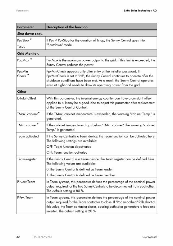
Shut-down requ.PpvStop * If Ppv < PpvStop for the duration of Tstop, the Sunny Central goes into
"Shutdown" mode.TstopGrid Monitor.PacMax * PacMax is the maximum power output to the grid. If this limit is exceeded, the
Sunny Central reduces the power. PpvMinCheck *
PpvMinCheck appears only after entry of the installer password. If PpvMinCheck is set to "off", the Sunny Central continues to operate after the shutdown conditions have been met. As a result, the Sunny Central operates even at night and needs to draw its operating power from the grid.
OtherE-Total Offset With this parameter, the internal energy counter can have a constant offset
applied to it. It may be a good idea to adjust this parameter after replacement of the Sunny Central Control.
TMax. cabinet* If the TMax. cabinet temperature is exceeded, the warning "cabinet Temp." is generated.
TMin. cabinet* If the cabinet temperature drops below "TMin. cabinet", the warning "cabinet Temp." is generated.
Team activated If the Sunny Central is a Team device, the Team function can be activated here. The following settings are available:OFF: Team function deactivatedON: Team function activated
Team-Register If the Sunny Central is a Team device, the Team register can be defined here. The following values are available:0: the Sunny Central is defined as Team leader.1: the Sunny Central is defined as Team member.
P-Next Team In Team systems, this parameter defines the percentage of the nominal power output required for the two Sunny Centrals to be disconnected from each other. The default setting is 80 %.
P-Prv. Team In Team systems, this parameter defines the percentage of the nominal power output required for the Team contactor to close. If "Pac smoothed" falls short of this value, the Team contactor closes, causing both solar generators to feed one inverter. The default setting is 20 %.
Parameter Description of the function

SMA Solar Technology AG Parameters
User Manual SC-BEN092751 31
6.2 Default Parameter SettingsThe following table summarizes the main operating parameters, and includes the adjusting range and default value of each parameter. The adjusting range and default value depend on the Sunny Central model. The parameters shown here with a gray background are only visible / adjustable after the installer password has been entered (see section 5.4 "Entering the Password" (page 26)).
Tau-FP* A damping function for the switching points helps minimize the number of switchings and thus lengthen the service life of the Team contactor. This parameter influences "Pac smoothed".
Parameter Range DefaultVmppMin 275 - 400 V (Sunny Central LV)
450 - 600 V300 V (Sunny Central LV)450 V
dVreference 5 V - 200 V (Sunny Central LV)5 V - 200 V
60 V (Sunny Central LV)80 V
PsearchMpp 0 - 25000 W device-specific settingTsearchMpp 60 - 3600 s 600 sdVtrack 1 - 10 V 5 V/TaMpTcheckMpp 5 - 60 s 10 sMpp Factor 0.20 - 1.00 0.80TrackCnt 5 - 20 7VpvStart 300 - 600 V (Sunny Central LV)
450 - 800 V400 V (Sunny Central LV)600 V
Tstart 1 - 600 s 90 sTwait 0 - 1800 s 600 sPpvStop 0 - 10000 W device-specific settingTstop 1 - 300 s 60 sPacMax 3 - 500 kW device-specific settingTMax. cabinet 30 - 70 °C 50 °CTMin. cabinet -30 - 10 °C -20 °C
Parameter Description of the function

Parameters SMA Solar Technology AG
32 SC-BEN092751 User Manual
6.3 Adjusting Parameters
The Sunny Central parameters can be adjusted as follows:
Impaired Functionality of Sunny Central due to Altered ParametersImproperly altered parameters can partly or completely impair the functionality of the Sunny Central.
• Parameters marked with * may only be adjusted upon consultation with SMA (see section 6.3 "Adjusting Parameters" (page 32)).
• After work has been carried out on the Sunny Central Control, it must then be relocked, in order to prevent third parties from changing the parameters.
Adjusting ParametersThese instructions describe how you can adjust parameters at the Sunny Central Control. You can use the following possibilities and tools to adjust the parameters:
• At the Sunny Central with the Sunny Central Control• On site with a laptop and the Sunny Data Control software• From a PC via remote access, with Sunny Data Control
The Sunny Data Control documentation describes how you can adjust parameters with Sunny Data Control.
1. Enter the password as described in section 5.4 "Entering the Password" (page 26).
2. In the online info display, press [ESC].
3. Navigate to the "Device Set-up“ menu with the [ ↓ ] arrow button, and select it by pressing [ENTER].
[ESC]
Status MPPPac 85.7kWE_Today 357.5kWhE_Total2512.3kWh
3 x [ ↓ ]
[ENTER]
[ Main Menu ] Operating Data Spot Values Long-Term Data → Device Set-up

SMA Solar Technology AG Parameters
User Manual SC-BEN092751 33
Resetting ParametersTo reset parameters, proceed as described above, and enter your Sunny Central's original values.
4. Navigate to the "Parameters“ menu with the [ ↓ ] arrow button, and select it by pressing [ENTER].
5. Select the menu in which you wish to adjust a parameter, by pressing [ENTER].
6. Select the parameter that you would like to change, by pressing [ENTER].
7. Take note of the previous value of the parameter.8. Adjust the parameter as discussed with SMA.9. Confirm your adjustment using [ENTER].
2 x [ ↓ ]
[ENTER]
[Device Set-up ] Password System→ Parameters ↓
[ENTER]
[ Parameters ]Param.-Function.........................------------------------------------- Mpp Limit. Val. Mpp Tracking Start requiremt Shut-down requ. Grid Monitor. Other

Communication SMA Solar Technology AG
34 SC-BEN092751 User Manual
7 CommunicationWith the option "NET Piggy-Back", the Sunny Central Control can be remotely monitored, and can send you e-mail reports regarding the operating mode, or present failures. Depending on your order preferences, the Sunny Central is delivered ex works either without communication, or with a NET Piggy-Back in one of the three following variants:
• Analog• ISDN
• Ethernet
The connection of the Sunny Central Control to the telephone line, to a router, or to a PC, is described in the NET Piggy-Back documentation.The Sunny Central Control is preconfigured for the respective communication type. If you wish to receive e-mail reports, you must specify this in the menu "Remote-Info".
7.1 Remote-Info1. Enter the password as described in section 5.4 "Entering the
Password" (page 26).2. In the online info display, press [ESC].
3. Navigate to the "Device Set-up“ menu with the [ ↓ ] arrow button, and select it by pressing [ENTER].
[ESC]
Status MPPPac 85.7kWE_Today 357.5kWhE_Total2512.3kWh
3 x [ ↓ ]
[ENTER]
[ Main Menu ] Operating Data Spot Values Long-Term Data → Device Set-up

SMA Solar Technology AG Communication
User Manual SC-BEN092751 35
4. Navigate to the "NET/eMail“ menu with the [ ↓ ] arrow button, and select it by pressing [ENTER].
5. Navigate to the "Remote-Info“ menu with the [ ↓ ] arrow button, and select it by pressing [ENTER].
6. The menu shown to the right appears.
6 x [ ↓ ]
[ENTER]
[Device Set-up ] Password System Parameters Interfaces Data archives SMUs→ NET/eMail
1 x [ ↓ ]
[ENTER]
[ NET/Email ] NET→ Remote-Info
[ENTER]
[ REMOTE-INFO ]E-mail ...Deactivated------------------------------- Events Recipient Sender ISP Account SMTP Account Test-Report

Communication SMA Solar Technology AG
36 SC-BEN092751 User Manual
7.2 Activating E-mail Reports
7.3 Entering or Changing E-Mail Addresses
1. Select the "Remote-Info" menu as described in section 7.1 "Remote-Info" (page 34).
2. Press [ENTER].3. The line "deactivated" begins to flash.4. With the [ ↓ ] arrow button, change the menu item to
"activated“.5. Confirm your adjustment by pressing [ENTER] twice.
1. Select the "Remote-Info" menu as described in section 7.1 "Remote-Info" (page 34).
2. Navigate to the "Recipient“ menu with the [ ↓ ] arrow button, and select it by pressing [ENTER].
3. On the first line, enter a company name. Confirm your entry using [ENTER].
4. On the second line, enter your name. Confirm your entry using [ENTER].
5. Enter your e-mail address on the third line. Confirm your entry using [ENTER].
6. On lines four and five, you can specify two additional e-mail addresses, to which the reports are to be sent. Confirm your entry using [ENTER].
[ REMOTE-INFO ]E-mail→ ...activated-------------------------
2 x [ ↓ ]
[ENTER]
[ REMOTE-INFO ]E-mail ...deactivated----------------------------- Events→ Recipient
[ RECIPIENT ]Company/Name ...COMPANY SMITH ...MR. SMITH-------------------------------EMAIL TO
EMAIL CC1 .......................EMAIL CC2........................
SMA Solar Technology AG Communication
User Manual SC-BEN092751 37
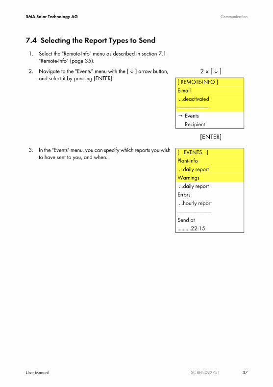
7.4 Selecting the Report Types to Send1. Select the "Remote-Info" menu as described in section 7.1
"Remote-Info" (page 35).2. Navigate to the "Events“ menu with the [ ↓ ] arrow button,
and select it by pressing [ENTER].
3. In the "Events" menu, you can specify which reports you wish to have sent to you, and when.
2 x [ ↓ ]
[ENTER]
[ REMOTE-INFO ]E-mail ...deactivated-----------------------------→ Events Recipient
[ EVENTS ]Plant-Info ...daily reportWarnings ...daily reportErrors ...hourly report--------------------------------Send at..........22:15

Communication SMA Solar Technology AG
38 SC-BEN092751 User Manual
Menu item Description Possible settingsPlant-Info reports the present values of your system, e.g. E-
Total, E-Today• no report• daily report
(recommended)Warnings reports the generated warning messages • no report
• hourly report• daily report
(recommended)Errors reports the failures which have occurred • no report
• hourly report (recommended)
• daily reportSend at Here, the time at which the daily report is to be
sent can be defined. We recommend setting the time to 22:15 (10.15 p. m.).
• time

SMA Solar Technology AG Communication
User Manual SC-BEN092751 39
7.5 Sending a Test ReportTo check the settings, you can send a test report.1. Select the "Remote-Info" menu as described in section 7.1
"Remote-Info" (page 35).2. Navigate to the "Test-Report“ menu with the [ ↓ ] arrow
button, and select it by pressing [ENTER].
3. The Sunny Central Control shows "Start" in the display. Press [ENTER] to send a test report.
If the test report cannot be sent, the display shown to the right appears. The meaning of the error code on the bottom line is described in the NET Piggy-Back documentation.
6 x [ ↓ ]
[ENTER]
[ REMOTE-INFO ]E-mail ...deactivated----------------------------- Events Recipient Sender ISP Account SMTP Account→ Test-Report
→ Start
[ TEST-REPORT ]→ Status... ...Error [5004]

External Sensors SMA Solar Technology AG
40 SC-BEN092751 User Manual
8 External SensorsThis section describes how the sensors are configured. The connection of sensors is described in the Sunny Central's installation guide. The connection points are shown in your Sunny Central's wiring diagrams.
8.1 Configuring the External SensorsIn total, two external analog sensors and one analog PT100 temperature sensor can be installed at the Sunny Central Control. You can use the analog inputs 3, 4 and 8 for the sensors.
Input Possible settings Default value Measured value34
deactivated, +/- 20 mA (jumper
required)+/- 10 mV+/- 20 mV+/- 50 mV
+/- 100 mV+/- 500 mV
+/- 1 V+/- 5 V
+/- 10 V
+/- 10 V analog measured value
8 PT100 PT100 PT100 temperature
1. Enter the password as described in section 5.4 "Entering the Password" (page 26).
2. In the online info display, press [ESC].
[ESC]
Status MPPPac 85.7kWE_Today 357.5kWhE_Total2512.3kWh

SMA Solar Technology AG External Sensors
User Manual SC-BEN092751 41
3. Navigate to the "Device Set-up“ menu with the [ ↓ ] arrow button, and select it by pressing [ENTER].
4. Navigate to the "Interfaces“ menu with the [ ↓ ] arrow button, and select it by pressing [ENTER].
5. Navigate to the "Analog In“ menu with the [ ↓ ] arrow button, and select it by pressing [ENTER].
6. Navigate to the desired analog input (Ain 3, Ain 4, or Ain 8) with the [ ↓ ] arrow button, and select it by pressing [ENTER].
3 x [ ↓ ]
[ENTER]
[ Main Menu ] Operating Data Spot Values Long-Term Data → Device Set-up
3 x [ ↓ ]
[ENTER]
[Device Set-up ] Password System Parameters → Interfaces ↕
1 x [ ↓ ]
[ENTER]
[ Interfaces ] Communication----------------------------------→ Analog In ↓
[ENTER]
[ Analog In ] Ain 1 R-Iso→ Ain 3 Ain 4 Ain 5 Ain 6 Ain 7 Ain 8

External Sensors SMA Solar Technology AG
42 SC-BEN092751 User Manual
7. You are presented with a detailed view of the selected analog input.
Menu item MeaningFunction AIn x Function of the analog input
Possible settings Meaningdeactivated the analog input is deactivated+/- 20 mA current measurement -20 mA to +20 mA+/- 10 mV voltage measurement -10 mV to +10 mV+/- 20 mV voltage measurement -20 mV to +20 mV+/- 50 mV voltage measurement -50 mV to +50 mV+/- 100 mV voltage measurement -100 mV to +100 mV+/- 500 mV voltage measurement -500 mV to +500 mV+/- 1 V voltage measurement -1 V to +1 V+/- 5 V voltage measurement -5 V to +5 V+/- 10 V voltage measurement -10 V to +10 V
Name name of the analog inputUnit measurement unit of the analog inputGain conversion factorOffset value which is added
[ENTER]
[Ain 3 ]Function AIn 3 ....................---Name Ain 3Unit mVGain 1Offset 0

SMA Solar Technology AG External Sensors
User Manual SC-BEN092751 43
8.2 Calculating Gain and Offset1. To activate the analog input, you must select a
measurement range for the analog sensor (e.g. +/- 10 V).2. Name the sensor (e.g. Temperature).3. Enter the unit of measurement (e.g. W/m²).4. The displayed value is calculated by means of:
– the value measured by the sensor,– the value which you have specified as the gain, and– the value which you have specified as the offset.
5. The gain factor is obtained by dividing the display range by the measuring range.
6. The offset is calculated by subtracting the product of the gain factor and the lower end of the measuring range from the lower end of the display range.Offset = lower end of display range - (gain factor * lower end of measuring range)
Expressed in formulas:M is a value measured in a range between Ml and Mu.D is the value displayed in a range between Dl and Du.
Explanation of the Abbreviations Used
Gain: G = (Du - Dl) / (Mu - Ml)Offset: O = Dl - (G * Ml)Displayed value: D = (G * M) + O
M measured value Mu upper end of measuring rangeMl lower end of measuring range O offsetG gain D displayed valueDu upper end of display range Dl lower end of display range
[Ain 3 ]Function AIn 3 ...+/- 10VName RadiationUnit W/m²Gain 135Offset 0
Gain factor =Display range
Measuring range

External Sensors SMA Solar Technology AG
44 SC-BEN092751 User Manual
Example Calculations: PyranometerA pyranometer has an output voltage of 0 to 10 V. This corresponds to irradiation of 0 to 1350 W/m².
If M = 5 V:
Example Calculations: Temperature SensorA temperature sensor with a converter outputs 4 - 20 mA. This corresponds to a temperature range of -30 to 80 °C.
If M = 4 mA:
Ml = 0 V Mu = 10 VDl = 0 W/m² Du = 1350 W/m²
Formula CalculationG = (Du - Dl) / (Mu - Ml) G = (1350 - 0) / (10 - 0) = 135O = Dl - (G * Ml) O = 0 - (135 * 0) = 0 W/m²
Formula CalculationD = (G * M) + O 135 * 5 + 0 = 675
Ml = 4 mA Mu = 20 mADl = -30 °C Du = 80 °C
Formula CalculationG = (Du - Dl) / (Mu - Ml) G = (80 - (-30)) / (20 - 4) = 6.875O = Dl - (G * Ml) O = (-30) - (6.875 * 4) = -57.5 °C
Formula CalculationD = (G * M) + O 4 * 6.875 + (-57.5) = -30
SMA Solar Technology AG Failures and Warnings
User Manual SC-BEN092751 45
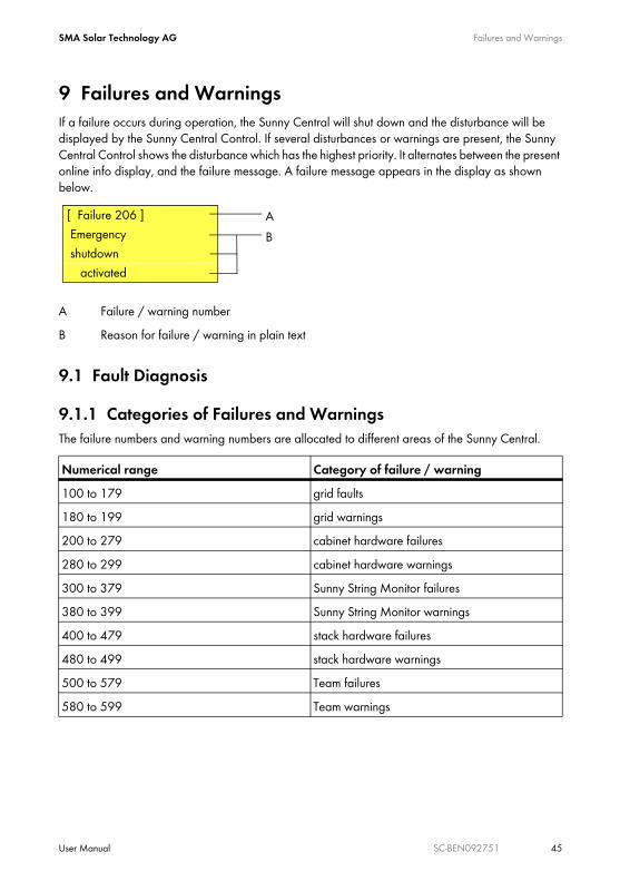
9 Failures and WarningsIf a failure occurs during operation, the Sunny Central will shut down and the disturbance will be displayed by the Sunny Central Control. If several disturbances or warnings are present, the Sunny Central Control shows the disturbance which has the highest priority. It alternates between the present online info display, and the failure message. A failure message appears in the display as shown below.
9.1 Fault Diagnosis
9.1.1 Categories of Failures and WarningsThe failure numbers and warning numbers are allocated to different areas of the Sunny Central.
A Failure / warning numberB Reason for failure / warning in plain text
Numerical range Category of failure / warning100 to 179 grid faults180 to 199 grid warnings200 to 279 cabinet hardware failures280 to 299 cabinet hardware warnings300 to 379 Sunny String Monitor failures380 to 399 Sunny String Monitor warnings400 to 479 stack hardware failures480 to 499 stack hardware warnings500 to 579 Team failures580 to 599 Team warnings
[ Failure 206 ] Emergency shutdown activated
AB

Failures and Warnings SMA Solar Technology AG
46 SC-BEN092751 User Manual
9.1.2 Types of Failures and WarningsSunny Central failures and warnings are subdivided into four types:Error Type 1 (Warning)The Sunny Central does not switch itself off. Once the error is no longer present, the error message is reset automatically. Check the system. Error Type 2 (Failure)The Sunny Central switches itself off. Once the fault is no longer present, the error message is reset automatically, and the Sunny Central starts up again. Error Type 3 (Failure)The Sunny Central switches itself off. Error type 3 only arises if the Sunny Central is feeding the grid when a fault occurs. Once the fault is no longer present, the error message is reset automatically, and the Sunny Central starts up again. Error Type 4 (Failure)Error type 4 must be confirmed before the Sunny Central can resume operation.The Sunny Central switches itself off. Rectify the cause of the fault, and confirm the error at the Sunny Central Control, or with Sunny Data Control. Once you have confirmed the error, the Sunny Central starts up again.

SMA Solar Technology AG Failures and Warnings
User Manual SC-BEN092751 47
9.1.3 WarningsNo. Description281 Error text:
Ground fault or SPD defectError type 1
Cause:The alert chain is interrupted (refer to the wiring diagram).
• Overvoltage protector damaged.• Back-up fuse(s) damaged on the grid side or generator side (if present).• The solar power system's insulation resistance is lower than the set threshold value.• The transformer's biasing circuit breaker has tripped.
Corrective measures:• Check fault signaling of the overvoltage protectors, and replace protector if
necessary.• Check the back-up fuse(s) of the overvoltage protector and replace it / them if
necessary.• Check the resistance of the solar power system. • In the event of an insulation fault, check strings under load-free conditions. Separate
and connect individual strings to determine which string is faulty.• Check the function of the ground fault monitor.• Switch biasing circuit breaker of the transformer back on.
283 Error text:cabinet Temp.
Error type 1
Cause:The threshold value (parameter TMin or TMax) for the permissible cabinet temperature has been breached (too high or too low).Corrective measures:
• Check function of cabinet cooling fans.• Clean or replace dirty air filters.• Check ambient temperature, and adjust if necessary.

Failures and Warnings SMA Solar Technology AG
48 SC-BEN092751 User Manual
380 Error text:SMU
Error type 1
Cause:The string monitoring system has detected one or more faulty strings or overvoltage protectors.Corrective measures:
• Under "Device Set-up -> SMUs -> Devices -> Measured Values", read out the individual string currents to detect the faulty string.
• More detailed information can be found in the Sunny String Monitor manual.381 Error text:
ser. com. with SMU disturbedError type 1
Cause:Communication failure between Sunny Central and the Sunny String Monitors.Corrective measures:
• Check communication lines and connections.• More detailed information can be found in the Sunny String Monitor manual.
382 Error text:thievery solar panel
Error type 1
Cause:Signal loop for theft detection at the Sunny String Monitor has been interrupted.Corrective measures:
• Check string currents.• Check signal loop.• For further details, refer to the installation guide and user manual of the Sunny String
Monitor or Sunny String Monitor Cabinet.
No. Description
SMA Solar Technology AG Failures and Warnings
User Manual SC-BEN092751 49
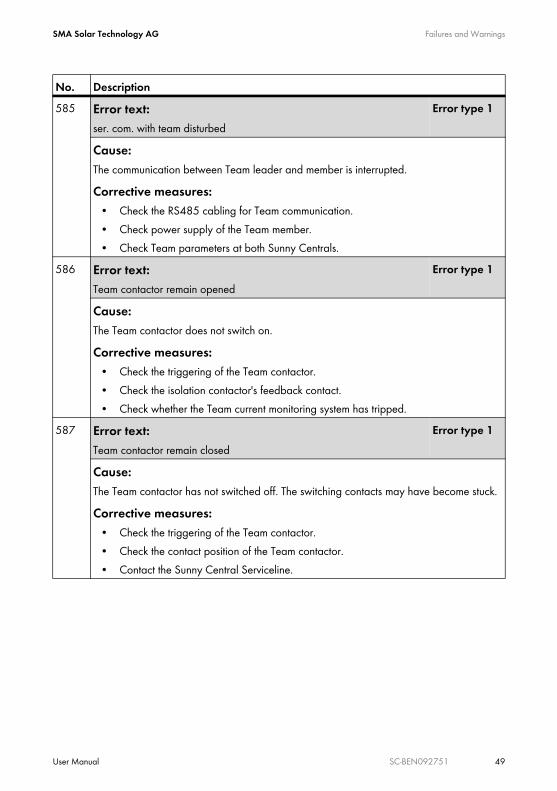
585 Error text:ser. com. with team disturbed
Error type 1
Cause:The communication between Team leader and member is interrupted.Corrective measures:
• Check the RS485 cabling for Team communication.• Check power supply of the Team member.• Check Team parameters at both Sunny Centrals.
586 Error text:Team contactor remain opened
Error type 1
Cause:The Team contactor does not switch on.Corrective measures:
• Check the triggering of the Team contactor.• Check the isolation contactor's feedback contact.• Check whether the Team current monitoring system has tripped.
587 Error text:Team contactor remain closed
Error type 1
Cause:The Team contactor has not switched off. The switching contacts may have become stuck.Corrective measures:
• Check the triggering of the Team contactor.• Check the contact position of the Team contactor.• Contact the Sunny Central Serviceline.
No. Description

Failures and Warnings SMA Solar Technology AG
50 SC-BEN092751 User Manual
588 Error text:Team contactor was opened
Error type 1
Cause:The Team contactor was switched off by the Team current monitoring system.Corrective measures:
• Check the triggering of the Team contactor.• Check the Team current monitoring system (settings, defect).• Check the Team current, may be too high due to asymmetrical current distribution.• Contact the Sunny Central Serviceline.
No. Description

SMA Solar Technology AG Failures and Warnings
User Manual SC-BEN092751 51
9.1.4 FailuresNo. Description104 Error text:
No Grid SynchronizationError type 3
Cause:Left-hand rotary field or internal device fault.Corrective measures:
• Check (right-hand) rotary field.• Check whether all internal fuses are switched on.• Contact the Sunny Central Serviceline.
105 Error text:Grid voltage too low
Error type 2
Cause:Voltage on the AC side is below the permitted range.Corrective measures:
• Check the grid connections.• Check grid stability.
106 Error text:Grid voltage too high
Error type 2
Cause:Voltage on the AC side is above the permitted range.Corrective measures:
• Check the grid connections.• Check grid stability.
110 Error text:UVW-Range
Error type 2
Cause:Voltage on phase L1, L2, or L3 outside the permitted range.Corrective measures:
• Check the grid connections.• Check grid stability.

Failures and Warnings SMA Solar Technology AG
52 SC-BEN092751 User Manual
111 Error text:Grid frequency too high or too low
Error type 2
Cause:Frequency on the AC side is outside the permitted range.Corrective measures:
• Check the grid connections.• Check grid stability.• Check right-hand rotary field.
201 Error text:Ground Fault 2 or plant temp. too high
Error type 2
Cause:• The overtemperature fault chain is interrupted (refer to the wiring diagram).• Cabinet overtemperature• Transformer overtemperature• Diode overtemperature• The insultation resistance of the solar power system is lower than the set threshold
value.• GFDI tripped.
Corrective measures:• Check function of cooling fans.• Clean or replace dirty air filters.• Ambient or cooling air temperature too high.• Check solar generator's insulation resistance.• In the event of an insulation fault, separate and connect individual strings to detect the
faulty one.• Check the function of the ground fault monitor.• Check the GFDI (see "Additional Notes for Sunny Central M/P Inverters for Grounded
Operation of the Solar Generator").
No. Description

SMA Solar Technology AG Failures and Warnings
User Manual SC-BEN092751 53
206 Error text:Emergency shutdown activated
Error type 4
Cause:Own emergency shut-off of the inverter activated.Corrective measures:Deactivate the emergency shut-off and confirm the failure as described in section 9.2 "Confirming Errors at the Sunny Central Control" (page 58).
209 Error text:DC Short circuit
Error type 4
Cause:An internal short circuit was detected on the DC side within the inverter. The DC switch was switched off.Corrective measures:
• Check the Sunny Central from the outside.• If possible, the Sunny Central should be externally isolated.• Contact the Sunny Central Serviceline.
215 Error text:heat sink fan fault
Error type 2
Cause:• Motor overload switch for fan(s) for cooling the power module has tripped.• Overtemperature protection for fan(s) for cooling the power module has tripped.• Ambient or cooling air temperatures too high.
Corrective measures:• Switch the motor overload switch back on.• Check function of cooling fans.• Clean soiled air inlet or heatsink.• If this error occurs frequently, contact the Sunny Central Serviceline.
No. Description

Failures and Warnings SMA Solar Technology AG
54 SC-BEN092751 User Manual
217 Error text:DC CB tripped or door switch open
Error type 2
Cause:• The cabinet door was opened during operation.• The DC circuit breaker was tripped due to an internal fault.• The reverse current monitoring system on the DC side has switched off.• The EVR resistor's current monitoring system has tripped.
Corrective measures:• Close the cabinet doors.• Check the function of the door switches.• Check the function and activation of the emergency shut-off relay.• Check reverse current monitoring system.• Visually inspect the chopper module and the EVR resistors.• Contact the Sunny Central Serviceline.
220 Error text:Release or Reset Signal faulty
Error type 2
Cause:The release signal or confirmation signal of the inverter bridge is defective.Corrective measures:If this error is always present, contact the Sunny Central Serviceline.
221 Error text:CHOPPER overtemperature
Error type 3
Cause:• EVR resistor overtemperature.• Defective chopper module.• After 90 minutes, a new startup attempt occurs.
Corrective measures:• Check resistor for dirt.• Ventilate resistor sufficiently.• Contact the Sunny Central Serviceline.
No. Description

SMA Solar Technology AG Failures and Warnings
User Manual SC-BEN092751 55
400 Error text:internal failure of inverter bridge
Error type 2/3
Cause:Internal inverter bridge failure (e.g. symmetry fault, board voltage, undertemperature, sensor breakage).Corrective measures:If this error occurs frequently, contact the Sunny Central Serviceline.
402 Error text:
ser. com. with inverter bridge disturbedError type 2
Cause:• The RS485 communication between the inverter bridge and the Sunny Central Control
is interrupted.• The inverter bridge or the Sunny Central Control may be faulty.
Corrective measures:• Check the RS485 wiring. • If this error is always present, contact the Sunny Central Serviceline.
408 Error text:PV Overvoltage
Error type 3
Cause:DC voltage is too high on the generator side (software).Corrective measures:
• Immediately disconnect the solar generator from the Sunny Central! Risk of damage to the Sunny Central!
• Check DC voltage.• Check module wiring and system design.
No. Description

Failures and Warnings SMA Solar Technology AG
56 SC-BEN092751 User Manual
409 Error text:IGBT Stack Temperature
Error type 3
Cause:Heatsink temperature is too high (software).Corrective measures:
• Check function of the cooling fans of the inverter bridge.• Clean soiled air inlet or heatsink.• Ambient or cooling air temperature too high.• If this error occurs frequently, contact the Sunny Central Serviceline.
410 Error text:IGBT Stack Error Sum
Error type 3
Cause:Internal failure of the inverter bridge (e.g. DC overvoltage, overtemperature, defective driver, overcurrent).Corrective measures:If this error occurs frequently, contact the Sunny Central Serviceline.
411 Error text:IGBT Overcurrent or UVW phase fault ADAPSCP
Error type 3
Cause:Internal inverter bridge failure.Corrective measures:If this error occurs frequently, contact the Sunny Central Serviceline.
412 Error text:Overcurrent
Error type 3
Cause:Internal inverter bridge failure.Corrective measures:If this error occurs frequently, contact the Sunny Central Serviceline.
No. Description

SMA Solar Technology AG Failures and Warnings
User Manual SC-BEN092751 57
420 Error text:ADAPSCP overtemperature
Error type 3
Cause:Heatsink temperature is too high (hardware threshold).Corrective measures:
• Check function of the cooling fans of the inverter bridge.• Clean soiled air inlet or heatsink.• Ambient or cooling air temperature too high.• If this error occurs frequently, contact the Sunny Central Serviceline.
421 Error text:ADAPSCP Overvoltage DC voltage link
Error type 2
Cause:DC voltage is too high on the solar generator side (hardware threshold).Corrective measures:
• Immediately disconnect the solar generator from the Sunny Central! Risk of damage to the Sunny Central!
• Check DC voltage.• Check module wiring and system design.
No. Description

Failures and Warnings SMA Solar Technology AG
58 SC-BEN092751 User Manual
9.2 Confirming Errors at the Sunny Central Control1. Rectify the cause of the fault at the Sunny Central.2. In the online info display, press [ESC].
3. Select "Operating Data" by pressing [ENTER].
4. Select "Faults" by pressing [ENTER].
5. Select "Actual Faults" by pressing [ENTER].
[ESC]
Status MPPPac 85.7kWE_Today 357.5kWhE_Total2512.3kWh
[ENTER]
[ Main Menu ]→ Operating Data Spot Values Long-Term Data Device Set-up
[ENTER]
[ Plant Data ]→ Faults Plant Status Energy Yield Data Files Other
[ENTER]
[ Faults ]→ Current Faults----------------
SMA Solar Technology AG Failures and Warnings
User Manual SC-BEN092751 59
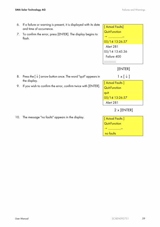
6. If a failure or warning is present, it is displayed with its date and time of occurrence.
7. To confirm the error, press [ENTER]. The display begins to flash.
8. Press the [ ↓ ] arrow button once. The word "quit" appears in the display.
9. If you wish to confirm the error, confirm twice with [ENTER].
10. The message "no faults" appears in the display.
[ENTER]
[ Actual Faults]Quit-Function→ ..................---05/14 13:26.57 Alert 28105/14 13:45.36 Failure 400:::::::::::::::
1 x [ ↓ ]
2 x [ENTER]
[ Actual Faults ]Quit-Functionquit05/14 13:26.57 Alert 281
[ Actual Faults ]Quit-Function→ ................--- no faults

Maintenance SMA Solar Technology AG
60 SC-BEN092751 User Manual
10 Maintenance
The Sunny Central must be maintained at regular intervals. Maintenance includes:• Inspection of wearing parts, and replacement thereof if necessary• Functionality test of components• Inspection of contact joints• Cleaning of cabinet interior if necessary
The maintenance intervals depend on the location and the ambient conditions. A Sunny Central installed in an environment with very dusty ambient air requires more frequent maintenance than indicated in the following table.
WARNING!Risk of lethal electric shock!
High voltages are present in the device.• All work on the Sunny Central must be carried out by a qualified electrician!• Open the Sunny Central for maintenance as described in the installation guide.

SMA Solar Technology AG Maintenance
User Manual SC-BEN092751 61
Time Intervals for Maintenance WorkMaintenance work Maintenance interval
(recommended)Read out long-term data and error memory. 1 month *
(depending on system size)
Clean or replace the filter material in the air inlet filters. 6 months *Clean the insect guards at the air inlets and outlets. 6 months *Clean the heatsink power module 12 months *Check the inside of the cabinet and the EVR resistor for heavy dust deposits, dirt, moisture, and water penetration from outside.If necessary, clean the Sunny Central and employ suitable corrective measures.
12 months
Check all power cable connections for looseness and tighten them if necessary. Check the connectors and insulation for discoloration or degradation. Replace any damaged connectors or corroded contacts.
12 months
Check adhesive warning labels and replace if necessary. 12 monthsCooling fans functionality test.Check all cooling fans for functionality and operating noise. The fans can be switched on by adjusting the thermostats, or during operation.If present: cabinet fan, heatsink fan(s), internal circulation fan(s), diode fan, heating fan
12 months
Heating functionality test. 12 monthsFunctionality test of all protective equipment present:
• leakage current circuit breakers• line circuit breakers• power switches• motor overload switches
by means of manual activation or by pressing the test button (if applicable).
12 months
Visually check all fuses and disconnectors, and lubricate the contacts if necessary.
12 months
Check overvoltage protectors. 12 months *Check the 230 V und 24 V control and auxiliary voltages. 12 monthsOvertemperature functionality test.Check the overtemperature safety circuit.
12 months

Maintenance SMA Solar Technology AG
62 SC-BEN092751 User Manual
* The maintenance interval may need to be shortened, depending on the location or ambient conditions.
Emergency shut-off functionality test.Check the function of the internal and external emergency shut-off switches.
12 months
Check the function of the door contacts. 12 monthsInsulation monitoring / GFDI functionality test.Check the function and the signaling.
12 months
Regular Data BackupsBackup and archive the Sunny Central Control data regularly with Sunny Data Control. This can occur by means of remote querying, or during routine maintenance.
Maintenance work Maintenance interval (recommended)

SMA Solar Technology AG Contact
User Manual SC-BEN092751 63
11 ContactIf you have technical problems with our products, contact the SMA Service Line. We require thefollowing information in order to provide you with the necessary assistance:
• Inverter type• Type and number of modules connected• Communication method• Serial number of the Sunny Central• Sunny Central failure or warning number• Sunny Central display message
SMA Solar Technology AG Sonnenallee 134266 Niestetal, GermanyTel. +49 561 9522 299Fax +49 561 9522 3299 [email protected] www.SMA.de

Contact SMA Solar Technology AG
64 SC-BEN092751 User Manual

SMA Solar Technology AG Contact
User Manual SC-BEN092751 65

Contact SMA Solar Technology AG
66 SC-BEN092751 User Manual

SMA Solar Technology AG Legal Restrictions
User Manual SC-BEN092751 67
The information contained in this document is the property of SMA Solar Technology AG. Publishing its content, either partially or in full, requires the written permission of SMA Solar Technology AG. Any internal company copying of the document for the purposes of evaluating the product or its correct implementation is allowed and does not require permission.
Exclusion of liabilityThe general terms and conditions of delivery of SMA Solar Technology AG shall apply.The content of these documents is continually checked and amended, where necessary. However, discrepancies cannot be excluded. No guarantee is made for the completeness of these documents. The latest version is available online at www.SMA.de or from the usual sales channels.Guarantee or liability claims for damages of any kind are excluded if they are caused by one or more of the following: • Damages during transportation• Improper or inappropriate use of the product• Operating the product in an unintended environment• Operating the product whilst ignoring relevant, statutory safety regulations in the deployment location• Ignoring safety warnings and instructions contained in all documents relevant to the product• Operating the product under incorrect safety or protection conditions• Altering the product or supplied software without authority• The product malfunctions due to operating attached or neighboring devices beyond statutory limit values• In case of unforeseen calamity or force majeureThe use of supplied software produced by SMA Solar Technology AG is subject to the following conditions:• SMA Solar Technology AG rejects any liability for direct or indirect damages arising from the use of software developed by
SMA Solar Technology AG. This also applies to the provision or non-provision of support activities.• Supplied software not developed by SMA Solar Technology AG is subject to the respective licensing and liability agreements
of the manufacturer.
SMA Factory WarrantyThe current guarantee conditions come enclosed with your device. These are also available online at www.SMA.de and can be downloaded or are available on paper from the usual sales channels if required.
TrademarksAll trademarks are recognized even if these are not marked separately. Missing designations do not mean that a product or brand is not a registered trademark.The Bluetooth® word mark and logos are registered trademarks owned by Bluetooth SIG, Inc. and any use of such marks by SMA Solar Technology is under license.SMA Solar Technology AGSonnenallee 134266 NiestetalGermanyTel. +49 561 9522-0Fax +49 561 9522-100www.SMA.deE-Mail: [email protected]© 2004 to 2009 SMA Solar Technology AG. All rights reserved

SMA Solar Technology AG
Sonnenallee 1
34266 Niestetal, Germany
Tel.: +49 561 9522 4000
Fax: +49 561 9522 4040
E-Mail: [email protected]
Freecall: 0800 SUNNYBOY
Freecall: 0800 78669269
www.SMA.de