Embed Size (px)
Citation preview

File name: Central-I - Hardware Manual -Amplifier CiG1-AMP01-
1A-01-00 V1.16
Date: Sunday, Aug14, 2016
Version: 1.16
Author: Agito-Akribis
Pages: 36
Central-I - Hardware Manual -Amplifier CiG1-AMP01-1A-01-00 V1.16
Page 1
Central-I Family
CiG1-AMP01-1A-01-00
Hardware User's Manual

File name: Central-I - Hardware Manual -Amplifier CiG1-AMP01-
1A-01-00 V1.16
Date: Sunday, Aug14, 2016
Version: 1.16
Author: Agito-Akribis
Pages: 36
Central-I - Hardware Manual -Amplifier CiG1-AMP01-1A-01-00 V1.16
Page 2
Revision control table
Version Description Date
1.0 Initial (based on Hardware Manual of previous
hardware versions)
April 27,
2016 Eyal
1.1 Corrections and additions April 28,
2016 Gregory
1.11 Rearrange and write the new manual based on
the previous hardware manual for AG300
August 10,
2016 YiQing
1.12
Small corrections: Rename Document, removed
other product variants from product variant
section, file reformatting, corrections to some
descriptions CJ
August 11,
2016 CJ
1.13
Added References, Created Product structure
section, Created captions for all pictures,
descriptions to be added
August 12,
2016 CJ
1.14 Added features of the product and description for
each part of this amplifier board
August 14
2016 YiQing
1.15 Added the motor selection criteria for this
amplifier
August 17
2016 YiQing
1.16 Change the connector from AMTEK to SAMTEC
Updated related pin out
November
15 2016 YiQing
1.17 Adding the bypass STO connection sample February 25
2017 YiQing
File name: Central-I - Hardware Manual -Amplifier CiG1-AMP01-
1A-01-00 V1.16
Date: Sunday, Aug14, 2016
Version: 1.16
Author: Agito-Akribis
Pages: 36
Central-I - Hardware Manual -Amplifier CiG1-AMP01-1A-01-00 V1.16
Page 3
Table of contents
Scope 4
PRODUCT STRUCTURE 4
CIGI-AMP01-1A-01-XX 4
SYSTEM STRUCTURE 5
Overview 5
Features 5
Number of axes 5
Supported motor types 5
Products' variants 6
AMPLIFIER – CIGI-AMP01-1A-01-00 7
LOGIC POWER CONNECTOR 8
Amplifier – J1 – Logic Power 8
AMPLIFIER BOARD CONNECTORS 9
Amplifier – J2 – Unit power 9
Amplifier – J3 - Regeneration 11
Amplifier – J4 – Motor Phases 13
Amplifier – J5 – STO 15
Amplifier – J8/J9– Encoders 18
Amplifier – J10/J12 – I/O Ports 21
Amplifier – J7– I/O Port 28
Amplifier – J11 - Static brakes 31
Amplifier– Communication Port 34
Environmental conditions 35
References 36

File name: Central-I - Hardware Manual -Amplifier CiG1-AMP01-
1A-01-00 V1.16
Date: Sunday, Aug14, 2016
Version: 1.16
Author: Agito-Akribis
Pages: 36
Central-I - Hardware Manual -Amplifier CiG1-AMP01-1A-01-00 V1.16
Page 4
Scope
This manual describes hardware interfaces of the CIG1-AMP01-1A-01-00. [1]
Product description Part numbers
Amplifier CIG1-AMP01-1A-01-00
The –XX defines a product's hardware variant, as describes below.
Product structure
CIG1-AMP01-1A-01-XX
The following pictures show the overall structure CIG1-AMP01-1A-01-XX Amplifier, that the XX
implies all variant types. All variants of this product type will use the same hardware that can
be depicted in Figure 1.
Figure 1: CiG1-AMP1-1A-01-XX Board Overview

File name: Central-I - Hardware Manual -Amplifier CiG1-AMP01-
1A-01-00 V1.16
Date: Sunday, Aug14, 2016
Version: 1.16
Author: Agito-Akribis
Pages: 36
Central-I - Hardware Manual -Amplifier CiG1-AMP01-1A-01-00 V1.16
Page 5
System Structure
Overview
The following section will discuss all the hardware functionality that is supported by this
product.
Features
This new amplifier board combines the function of controller and driver.
Precise control with integrated unit
Support different types of motor with minor hardware
Number of axes
The CIG1-AMP01-1A-01-00 (amplifier board) supports driving of up to 2 motors. This means
that the amplifier can drive various kinds of motors.
Supported motor types
The CIG1 amplifier can drive the following motor types:
1 DC-Brushless or Bipolar Stepper motor (each motor defined independently).
Up to 2 DC-Brush, Voice coil motors (each motor defined independently).
Future firmware will also support, with no hardware change, driving of 2 Brush motors.
Linear and rotary motors are both supported.
The table below is a sample to show what kind of motor from Akribis can be used on such a
certain kind of amplifier. The criteria are to compare the peak and continuous current of the
motor and the amplifier. If the continuous current and peak current is within the range of the
amplifier board, it means such a kind of motor can be supported by the CIGI amplifier.
No #
Amplifier Type Motor type
CIGI-AMP01-1A-01-02
AUM1 S1-S4; AUM2 S1-S4, S8; AUM3-S1…
ACM1-S30, S50, S80, S100…
CIGI-AMP01-1A-01-03
AUM1 S1-S2; AUM2 S1 (Series)…
AVM12-6.4; AVM19-5; AVM20-10; DGV16; XRV76…
File name: Central-I - Hardware Manual -Amplifier CiG1-AMP01-
1A-01-00 V1.16
Date: Sunday, Aug14, 2016
Version: 1.16
Author: Agito-Akribis
Pages: 36
Central-I - Hardware Manual -Amplifier CiG1-AMP01-1A-01-00 V1.16
Page 6
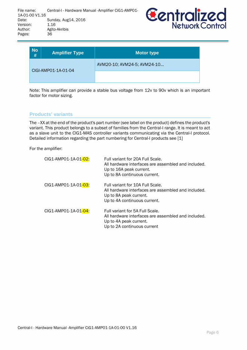
No #
Amplifier Type Motor type
CIGI-AMP01-1A-01-04
AVM20-10; AVM24-5; AVM24-10…
Note: This amplifier can provide a stable bus voltage from 12v to 90v which is an important
factor for motor sizing.
Products' variants
The –XX at the end of the product's part number (see label on the product) defines the product's
variant. This product belongs to a subset of families from the Central-I range. It is meant to act
as a slave unit to the CIG1-MAS controller variants communicating via the Central-I protocol.
Detailed information regarding the part numbering for Central-I products see [1]
For the amplifier:
CIG1-AMP01-1A-01-02: Full variant for 20A Full Scale.
All hardware interfaces are assembled and included.
Up to 16A peak current.
Up to 8A continuous current.
CIG1-AMP01-1A-01-03: Full variant for 10A Full Scale.
All hardware interfaces are assembled and included.
Up to 8A peak current.
Up to 4A continuous current.
CIG1-AMP01-1A-01-04: Full variant for 5A Full Scale.
All hardware interfaces are assembled and included.
Up to 4A peak current.
Up to 2A continuous current
File name: Central-I - Hardware Manual -Amplifier CiG1-AMP01-
1A-01-00 V1.16
Date: Thursday, Aug11, 2016
Version: 1.14
Author: Agito-Akribis
Pages: 36
Central-I - Hardware Manual -Amplifier CiG1-AMP01-1A-01-00 V1.16
Page 7
Power Connection
General
The following section will discuss the power connection of DC amplifier.
When use the CIG1-AMP01 to drive the motor, user should provide the module two parts of
power which is described in the following part. Meanwhile, user should carefully follow the
suggestion and detailed notes in the following sections to ensure the safety and correct use of
the CIG1-AMP01.
Power Supplies and Connection
The power of the CIG1-AMP01 is combined by two parts of power:
Logic 9V~36VDC power supply for both the logic signals and Isolated IO Power
Recommended Logic Power Supply Type: Meanwell S-100-24 Power Supply
Unit Power 12V~90VDC for motor driving.
Recommended Logic Power Supply Type: Meanwell T-60C Power Supply
It is always recommended to use a single “Ground Potential Point” for all supplies in
the system.
The CIG1-AMP01 provides isolated IOs, differential IOs and static brakes electrical interfaces.
If these functions are required by the application, external power supply can be used.
Wire and Cable selection
This section will describe rules in detail for choosing the cables and wires used in the CIG1-
AMP01 to ensure the high performance and low EMI of the whole system.
Use twisted pair shielded wires for the control, feedback and communication
The impedance of the wires must be as low as possible. The selection of the wires
should on the basis of the current consumption. Usually, the size of the wires should
be thicker than the real application current. Generally, a 24AWG wire is recommended
to be used for the logic, analog control and feedback signals.
Always use shielded cables for motor connection
Keep motor cable as far as possible from the control, feedback and communication
lines and cables
Keep all wires and cables as short as possible
Generally, under normal operating conditions, cables with shield should not carry any
current. If not, this may damage the controller and even the whole system.

File name: Central-I - Hardware Manual -Amplifier CiG1-AMP01-
1A-01-00 V1.16
Date: Thursday, Aug11, 2016
Version: 1.14
Author: Agito-Akribis
Pages: 36
Central-I - Hardware Manual -Amplifier CiG1-AMP01-1A-01-00 V1.16
Page 8
AMPLIFIER – CIG1-AMP01-1A-01-00
This document provides a detailed description of the interface of the amplifier.
Logic power connector
This chapter describes the amplifier's logic power connector.
Amplifier – J1 – Logic Power
Figure 2 Logic Power Port
Description: The graph above is about the logic power port on the amplifier board.
Manufacturer: DEGSON (Phoenix compatible)
P/N (product side): 15EDGRC3.504P1400AH
Pitch: 3.5mm
Mating Type: MC 1,5/4-ST-3,5
Pin #
Name Type Description
1 Isolated IO Power PWR - IN 9V~36VDC
2 Isolated IO Power Return PWR -IN IO Power Return
3 Backup/Logic Power PWR -IN 9VDC-36VDC
4 GND PWR -IN Logic power ground
Pin 1
File name: Central-I - Hardware Manual -Amplifier CiG1-AMP01-
1A-01-00 V1.16
Date: Thursday, Aug11, 2016
Version: 1.14
Author: Agito-Akribis
Pages: 36
Central-I - Hardware Manual -Amplifier CiG1-AMP01-1A-01-00 V1.16
Page 9
Amplifier board connectors
The chapter describes the connectors and interfaces of the amplifier board.
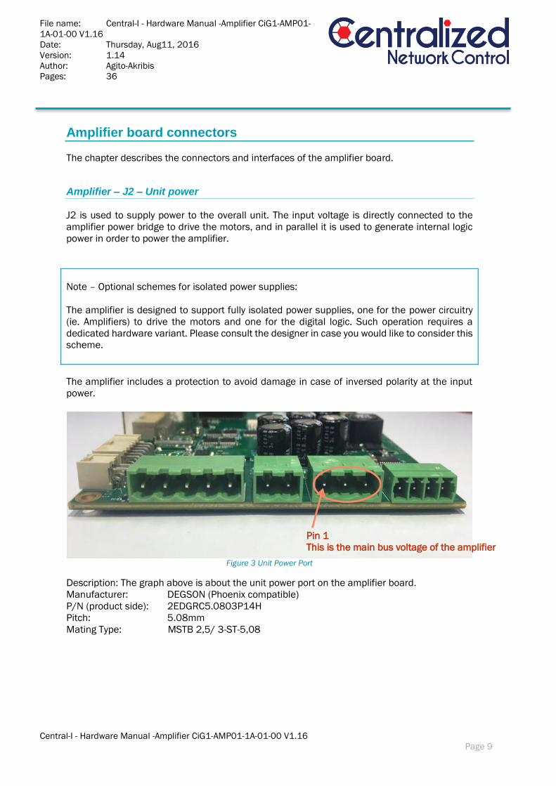
Amplifier – J2 – Unit power
J2 is used to supply power to the overall unit. The input voltage is directly connected to the
amplifier power bridge to drive the motors, and in parallel it is used to generate internal logic
power in order to power the amplifier.
Note – Optional schemes for isolated power supplies:
The amplifier is designed to support fully isolated power supplies, one for the power circuitry
(ie. Amplifiers) to drive the motors and one for the digital logic. Such operation requires a
dedicated hardware variant. Please consult the designer in case you would like to consider this
scheme.
The amplifier includes a protection to avoid damage in case of inversed polarity at the input
power.
Figure 3 Unit Power Port
Description: The graph above is about the unit power port on the amplifier board.
Manufacturer: DEGSON (Phoenix compatible)
P/N (product side): 2EDGRC5.0803P14H
Pitch: 5.08mm
Mating Type: MSTB 2,5/ 3-ST-5,08
Pin 1
This is the main bus voltage of the amplifier
File name: Central-I - Hardware Manual -Amplifier CiG1-AMP01-
1A-01-00 V1.16
Date: Thursday, Aug11, 2016
Version: 1.14
Author: Agito-Akribis
Pages: 36
Central-I - Hardware Manual -Amplifier CiG1-AMP01-1A-01-00 V1.16
Page 10
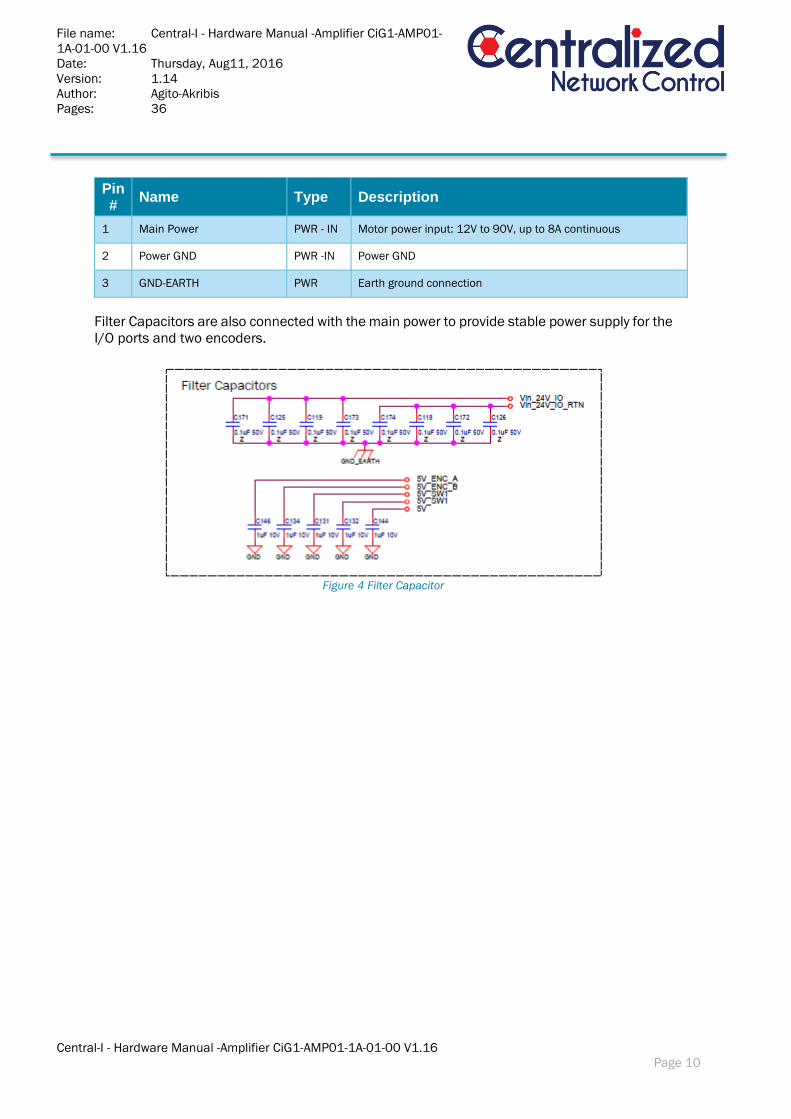
Pin #
Name Type Description
1 Main Power PWR - IN Motor power input: 12V to 90V, up to 8A continuous
2 Power GND PWR -IN Power GND
3 GND-EARTH PWR Earth ground connection
Filter Capacitors are also connected with the main power to provide stable power supply for the
I/O ports and two encoders.
Figure 4 Filter Capacitor
File name: Central-I - Hardware Manual -Amplifier CiG1-AMP01-
1A-01-00 V1.16
Date: Thursday, Aug11, 2016
Version: 1.14
Author: Agito-Akribis
Pages: 36
Central-I - Hardware Manual -Amplifier CiG1-AMP01-1A-01-00 V1.16
Page 11
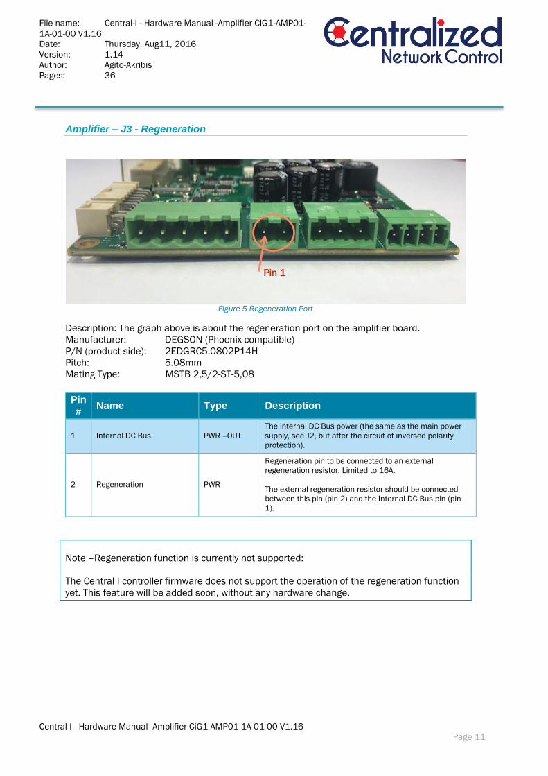
Amplifier – J3 - Regeneration
Figure 5 Regeneration Port
Description: The graph above is about the regeneration port on the amplifier board.
Manufacturer: DEGSON (Phoenix compatible)
P/N (product side): 2EDGRC5.0802P14H
Pitch: 5.08mm
Mating Type: MSTB 2,5/2-ST-5,08
Pin #
Name Type Description
1 Internal DC Bus PWR –OUT
The internal DC Bus power (the same as the main power
supply, see J2, but after the circuit of inversed polarity
protection).
2 Regeneration PWR
Regeneration pin to be connected to an external
regeneration resistor. Limited to 16A.
The external regeneration resistor should be connected
between this pin (pin 2) and the Internal DC Bus pin (pin
1).
Note –Regeneration function is currently not supported:
The Central I controller firmware does not support the operation of the regeneration function
yet. This feature will be added soon, without any hardware change.
Pin 1

File name: Central-I - Hardware Manual -Amplifier CiG1-AMP01-
1A-01-00 V1.16
Date: Thursday, Aug11, 2016
Version: 1.14
Author: Agito-Akribis
Pages: 36
Central-I - Hardware Manual -Amplifier CiG1-AMP01-1A-01-00 V1.16
Page 12
Electrical interfaces - Regeneration:
The circuitry involved in regeneration is depicted in the schematic bel
Figure 6 Regeneration circuit diagram
File name: Central-I - Hardware Manual -Amplifier CiG1-AMP01-
1A-01-00 V1.16
Date: Thursday, Aug11, 2016
Version: 1.14
Author: Agito-Akribis
Pages: 36
Central-I - Hardware Manual -Amplifier CiG1-AMP01-1A-01-00 V1.16
Page 13
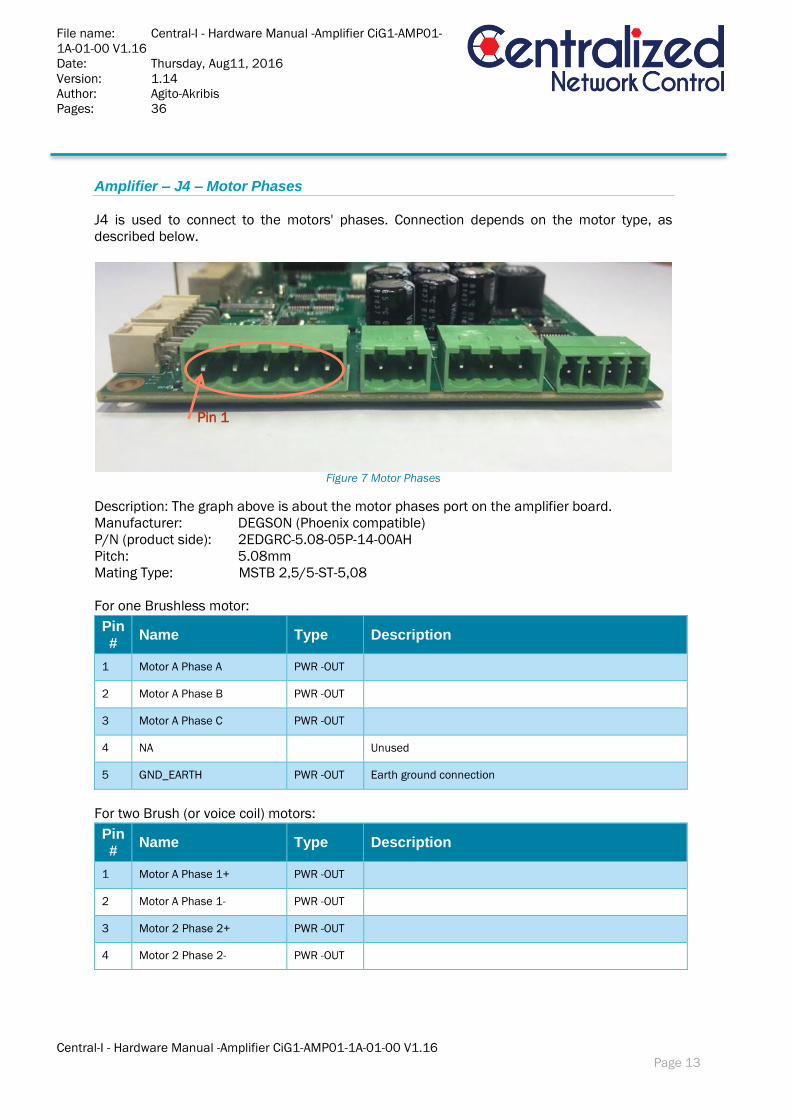
Amplifier – J4 – Motor Phases
J4 is used to connect to the motors' phases. Connection depends on the motor type, as
described below.
Figure 7 Motor Phases
Description: The graph above is about the motor phases port on the amplifier board.
Manufacturer: DEGSON (Phoenix compatible)
P/N (product side): 2EDGRC-5.08-05P-14-00AH
Pitch: 5.08mm
Mating Type: MSTB 2,5/5-ST-5,08
For one Brushless motor:
Pin #
Name Type Description
1 Motor A Phase A PWR -OUT
2 Motor A Phase B PWR -OUT
3 Motor A Phase C PWR -OUT
4 NA Unused
5 GND_EARTH PWR -OUT Earth ground connection
For two Brush (or voice coil) motors:
Pin #
Name Type Description
1 Motor A Phase 1+ PWR -OUT
2 Motor A Phase 1- PWR -OUT
3 Motor 2 Phase 2+ PWR -OUT
4 Motor 2 Phase 2- PWR -OUT
Pin 1

File name: Central-I - Hardware Manual -Amplifier CiG1-AMP01-
1A-01-00 V1.16
Date: Thursday, Aug11, 2016
Version: 1.14
Author: Agito-Akribis
Pages: 36
Central-I - Hardware Manual -Amplifier CiG1-AMP01-1A-01-00 V1.16
Page 14
5 GND_EARTH PWR -OUT Earth-ground connection
For one stepper motor:
Pin #
Name Type Description
1 Motor A Phase 1 + PWR -OUT
2 Motor A Phase 2 + PWR -OUT
3 Motor A Phases 1- and 2 - PWR -OUT Two motor wires are connected to a single pin of the
connector
4 NA Unused
5 GND_EARTH PWR -OUT Earth-ground connection
Note – Stepper voltage range:
Note that a bipolar stepper motor has two independent phases (total of 4 wires). With the
CIG1-AMP01, you need to connect the (-) wire of both phases together, into the third pin of
the connector (for motor A).
This connection implies a limitation of the voltage that will be applied to the stepper. For
example, if the power supply to the unit is 24v, each phase of the stepper motor will be
limited to 12v.
With suitable selection of the power supply this should impose no limitation on the stepper
motor operation.
User may connect different types of motors to motor A and to motor B. Just follow the above
instructions for each motor, independently.
File name: Central-I - Hardware Manual -Amplifier CiG1-AMP01-
1A-01-00 V1.16
Date: Thursday, Aug11, 2016
Version: 1.14
Author: Agito-Akribis
Pages: 36
Central-I - Hardware Manual -Amplifier CiG1-AMP01-1A-01-00 V1.16
Page 15
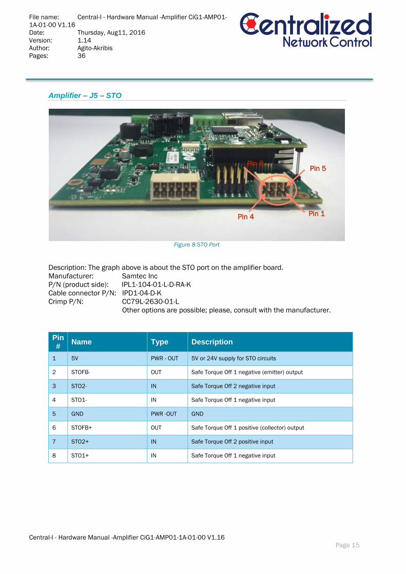
Amplifier – J5 – STO
Figure 8 STO Port
Description: The graph above is about the STO port on the amplifier board.
Manufacturer: Samtec Inc
P/N (product side): IPL1-104-01-L-D-RA-K
Cable connector P/N: IPD1-04-D-K
Crimp P/N: CC79L-2630-01-L
Other options are possible; please, consult with the manufacturer.
Pin #
Name Type Description
1 5V PWR - OUT 5V or 24V supply for STO circuits
2 STOFB- OUT Safe Torque Off 1 negative (emitter) output
3 STO2- IN Safe Torque Off 2 negative input
4 STO1- IN Safe Torque Off 1 negative input
5 GND PWR -OUT GND
6 STOFB+ OUT Safe Torque Off 1 positive (collector) output
7 STO2+ IN Safe Torque Off 2 positive input
8 STO1+ IN Safe Torque Off 1 negative input
Pin 1
Pin 5
Pin 4
Pin 8
File name: Central-I - Hardware Manual -Amplifier CiG1-AMP01-
1A-01-00 V1.16
Date: Thursday, Aug11, 2016
Version: 1.14
Author: Agito-Akribis
Pages: 36
Central-I - Hardware Manual -Amplifier CiG1-AMP01-1A-01-00 V1.16
Page 16
Notes – STO Implementation:
STO1 and STO2 are completely independent. Each one of them disables the power to
the motor in a different way.
Both STO1 and STO2 disable the power to the motor by hardware circuitry, without any
software intervention.
The circuitry, logic and redundancy of the STO implementation were done according to
safety standards. Yet, the design is to be tested and formally approved for the industry
standard.
The STO1 and STO2 are defined with a positive pin (+) and a negative pin (-). However
(refer to the electrical interfaces described below) the opto coupler at the STO input (as
for all other discrete, isolated inputs of the amplifier) is equipped with two input diodes,
enabling operation at "positive" or "negative" input voltage. The input is actually
activated by (enough) current at one of the input diodes, independently of the current
direct. This enables NPN or PNP connection to the STO inputs (each one of them
independently!).
The STO protection logic is designed such that the STO inputs (both of them) must be
powered in order to enable motor operation. Leaving an STO input disconnected will
prevent motor operation. This logic is required in order to ensure that a disconnected
safety cable will be considered by the control unit as an unsafe situation. When
(enough) current is driven through an STO input, the state of this input is "safe". When
no (not enough) current is driven through an STO input, the state of this input is
"unsafe".
The two STO inputs must be at "safe" state in order to enable motor operation.
Both STO1 and STO2, although acting on the drive hardware directly, are also sensed
by the controller software. The controller software is generating a feedback signal to
the user (STO_FB) which is also an isolated signal. This feedback is generated by the
software and is activated in case a least one of STO1 or STO2 signals unsafe situation.

File name: Central-I - Hardware Manual -Amplifier CiG1-AMP01-
1A-01-00 V1.16
Date: Thursday, Aug11, 2016
Version: 1.14
Author: Agito-Akribis
Pages: 36
Central-I - Hardware Manual -Amplifier CiG1-AMP01-1A-01-00 V1.16
Page 17
Electrical interfaces – STO:
Figure 9 STO Circuit Diagram
The electrical characteristics of the STO1 and STO2 inputs are identical to those of the
discrete, isolated inputs of the controller. Refer to the chapter about J10 below.
Notes –The connection of bypassing STO:
Connect the pin 1, pin7 and pin8 together and connect the pin 5 ,pin3 and pin4
together.
Pin #
UPPER LOWER
5 1
6 2
7 3
8 4

File name: Central-I - Hardware Manual -Amplifier CiG1-AMP01-
1A-01-00 V1.16
Date: Thursday, Aug11, 2016
Version: 1.14
Author: Agito-Akribis
Pages: 36
Central-I - Hardware Manual -Amplifier CiG1-AMP01-1A-01-00 V1.16
Page 18
Amplifier – J8/J9– Encoders
J8 and J9 are identical connectors. Each one is used to interface a single encoder, where J8 is
typically used for A axis, J9 is typically used for B axis.
Figure 10 Encoder Ports
Description: The graph above is about the encoder port on the amplifier board.
Manufacturer: SUNCHU.
P/N (product side): SC-MCR10S90A4G
Cable connector P/N: SC-10-4P
Other options are possible; please, consult with the manufacturer.
Pin #
Name Type Description
1 5V PWR - OUT 5V for user usage (up to 0.5A, each connector)
2 GND PWR -OUT Reference for 5V and differential signals
3 Encoder_1P Out Differential output, not inverted
4 Encoder_1N Out Differential output, inverted
5 Encoder_2P In Differential input, not inverted
6 Encoder_2N In Differential input, inverted
7 Encoder_3P In Differential input, not inverted
8 Encoder_3N In Differential input, inverted
9 Encoder_4P Bidirectional Differential input/output, not inverted
10 Encoder_4N Bidirectional Differential input/output, inverted
J8 J9
File name: Central-I - Hardware Manual -Amplifier CiG1-AMP01-
1A-01-00 V1.16
Date: Thursday, Aug11, 2016
Version: 1.14
Author: Agito-Akribis
Pages: 36
Central-I - Hardware Manual -Amplifier CiG1-AMP01-1A-01-00 V1.16
Page 19
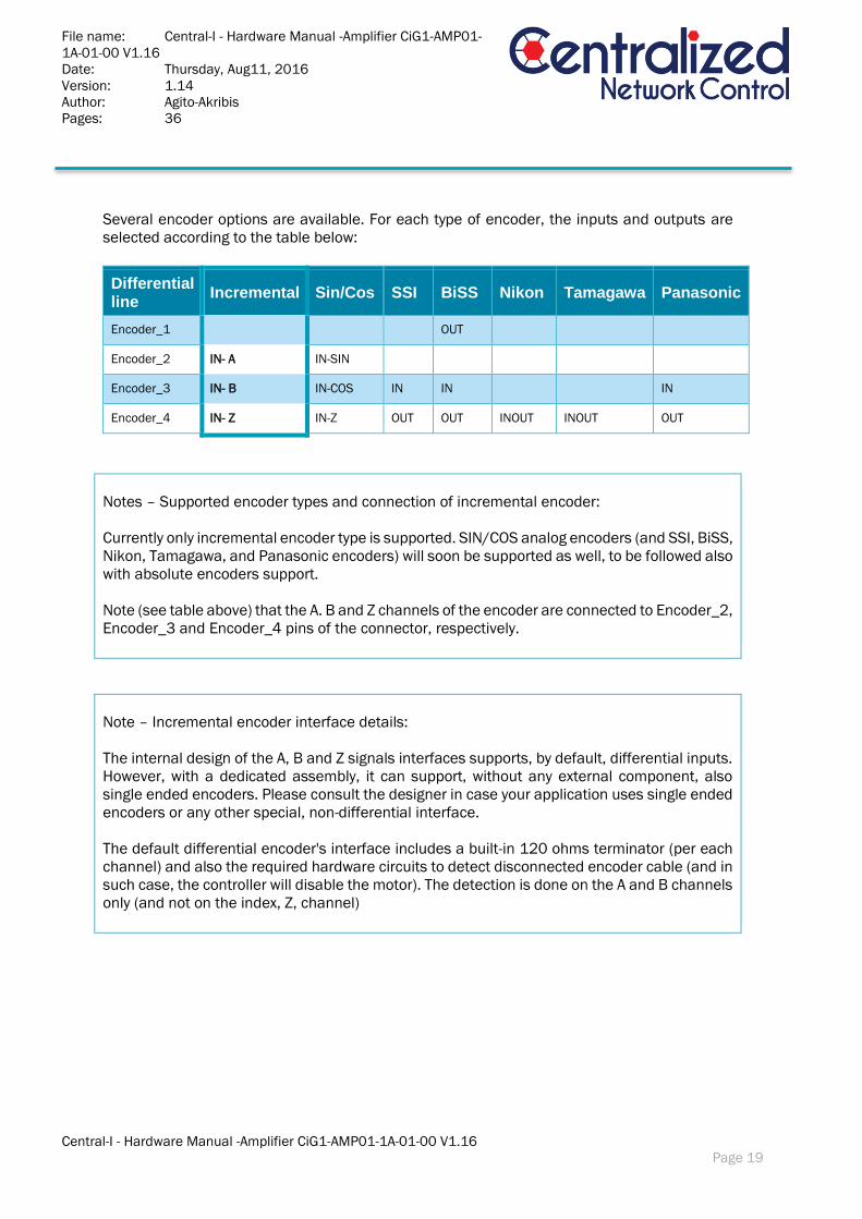
Several encoder options are available. For each type of encoder, the inputs and outputs are
selected according to the table below:
Differential line
Incremental Sin/Cos SSI BiSS Nikon Tamagawa Panasonic
Encoder_1 OUT
Encoder_2 IN- A IN-SIN
Encoder_3 IN- B IN-COS IN IN IN
Encoder_4 IN- Z IN-Z OUT OUT INOUT INOUT OUT
Notes – Supported encoder types and connection of incremental encoder:
Currently only incremental encoder type is supported. SIN/COS analog encoders (and SSI, BiSS,
Nikon, Tamagawa, and Panasonic encoders) will soon be supported as well, to be followed also
with absolute encoders support.
Note (see table above) that the A. B and Z channels of the encoder are connected to Encoder_2,
Encoder_3 and Encoder_4 pins of the connector, respectively.
Note – Incremental encoder interface details:
The internal design of the A, B and Z signals interfaces supports, by default, differential inputs.
However, with a dedicated assembly, it can support, without any external component, also
single ended encoders. Please consult the designer in case your application uses single ended
encoders or any other special, non-differential interface.
The default differential encoder's interface includes a built-in 120 ohms terminator (per each
channel) and also the required hardware circuits to detect disconnected encoder cable (and in
such case, the controller will disable the motor). The detection is done on the A and B channels
only (and not on the index, Z, channel)

File name: Central-I - Hardware Manual -Amplifier CiG1-AMP01-
1A-01-00 V1.16
Date: Thursday, Aug11, 2016
Version: 1.14
Author: Agito-Akribis
Pages: 36
Central-I - Hardware Manual -Amplifier CiG1-AMP01-1A-01-00 V1.16
Page 20
Note: 5v supply limitation:
Note that the 5v supply that is provided at pin 1 of each of the J8 and J9 connectors is internally
limited to 0.5A per each connector (independent limitation at each connector). This is in order
to protect the controller from short to GND.
Future firmware versions of the controller will be able to detect and report such fault and to
disable the 5v supply until the fault is fixed. Currently, the current will be limited, but the
detection of this limit and the shutting off of the 5v supply is not supported yet.
Physical Pin Layout – Encoder:
Pin #
Left Column Right Columm
1 * 2
3 4
5 6
7 8
9 10
The maximum current for each connector is 0.5A.
File name: Central-I - Hardware Manual -Amplifier CiG1-AMP01-
1A-01-00 V1.16
Date: Thursday, Aug11, 2016
Version: 1.14
Author: Agito-Akribis
Pages: 36
Central-I - Hardware Manual -Amplifier CiG1-AMP01-1A-01-00 V1.16
Page 21
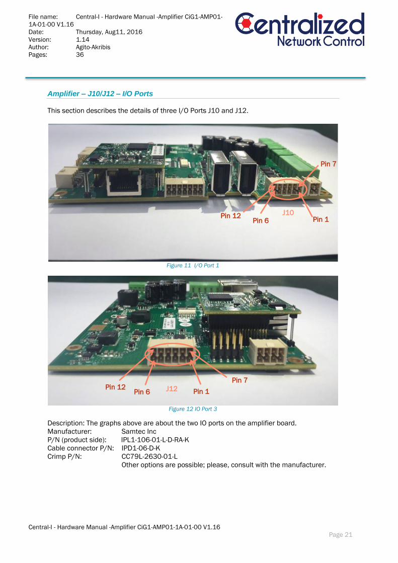
Amplifier – J10/J12 – I/O Ports
This section describes the details of three I/O Ports J10 and J12.
Figure 11 I/O Port 1
Figure 12 IO Port 3
Description: The graphs above are about the two IO ports on the amplifier board.
Manufacturer: Samtec Inc
P/N (product side): IPL1-106-01-L-D-RA-K
Cable connector P/N: IPD1-06-D-K
Crimp P/N: CC79L-2630-01-L
Other options are possible; please, consult with the manufacturer.
J10
J12 Pin 6
Pin 1
Pin 7
Pin 6 Pin 12
Pin 1
Pin 7 Pin 12
File name: Central-I - Hardware Manual -Amplifier CiG1-AMP01-
1A-01-00 V1.16
Date: Thursday, Aug11, 2016
Version: 1.14
Author: Agito-Akribis
Pages: 36
Central-I - Hardware Manual -Amplifier CiG1-AMP01-1A-01-00 V1.16
Page 22
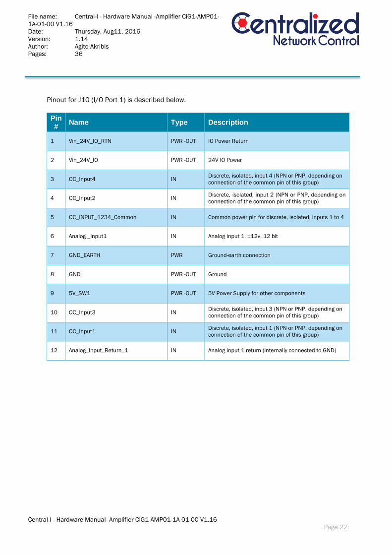
Pinout for J10 (I/O Port 1) is described below.
Pin #
Name Type Description
1 Vin_24V_IO_RTN PWR -OUT IO Power Return
2 Vin_24V_IO PWR -OUT 24V IO Power
3 OC_Input4 IN Discrete, isolated, input 4 (NPN or PNP, depending on
connection of the common pin of this group)
4 OC_Input2 IN Discrete, isolated, input 2 (NPN or PNP, depending on
connection of the common pin of this group)
5 OC_INPUT_1234_Common IN Common power pin for discrete, isolated, inputs 1 to 4
6 Analog _Input1 IN Analog input 1, ±12v, 12 bit
7 GND_EARTH PWR Ground-earth connection
8 GND PWR -OUT Ground
9 5V_SW1 PWR -OUT 5V Power Supply for other components
10 OC_Input3 IN Discrete, isolated, input 3 (NPN or PNP, depending on
connection of the common pin of this group)
11 OC_Input1 IN Discrete, isolated, input 1 (NPN or PNP, depending on
connection of the common pin of this group)
12 Analog_Input_Return_1 IN Analog input 1 return (internally connected to GND)

File name: Central-I - Hardware Manual -Amplifier CiG1-AMP01-
1A-01-00 V1.16
Date: Thursday, Aug11, 2016
Version: 1.14
Author: Agito-Akribis
Pages: 36
Central-I - Hardware Manual -Amplifier CiG1-AMP01-1A-01-00 V1.16
Page 23
Pinout for J12 (I/O Port 3) is described below.
Pin #
Name Type Description
1 Vin_24V_IO_RTN PWR -OUT IO Power Return
2 Vin_24V_IO PWR -OUT 24V IO Power
3 OC_Input11 IN Discrete, isolated, input 11 (NPN or PNP, depending
on connection of the common pin of this group)
4 OC_Input9 IN Discrete, isolated, input 9 (NPN or PNP, depending on
connection of the common pin of this group)
5 OC_INPUT_891011_Common IN Common power pin for discrete, isolated, inputs 1 to 4
6 Analog _Input2 IN Analog input 2, ±12v, 12 bit
7 GND_EARTH PWR Ground-earth connection
8 GND PWR -OUT Ground
9 5V_SW2 PWR -OUT 5V Power Supply for other components
10 OC_Input10 IN Discrete, isolated, input 10 (NPN or PNP, depending
on connection of the common pin of this group)
11 OC_Input8 IN Discrete, isolated, input 8 (NPN or PNP, depending on
connection of the common pin of this group)
12 Analog_Input_Return_2 IN Analog input 2 return (internally connected to GND)
Note – Analog outputs are not supported in some of the product variants:
Some variants of the product do not support the analog outputs. Please consult the designer
for ordering the correct variant in case you need analog outputs for your application.
Analog outputs are required in case you need to interface external amplifier over a ±10v
analog command, or in case you need analog output for any other general purpose.
File name: Central-I - Hardware Manual -Amplifier CiG1-AMP01-
1A-01-00 V1.16
Date: Thursday, Aug11, 2016
Version: 1.14
Author: Agito-Akribis
Pages: 36
Central-I - Hardware Manual -Amplifier CiG1-AMP01-1A-01-00 V1.16
Page 24
Note: 5v supply limitation:
Note that the 5v supply that is provided on both pin 9 in Port J10 and J12 is internally limited
to 0.5A (both pins together). This is in order to protect the amplifier from short to GND.
Future firmware version of the amplifier will be able to detect and report this fault and to disable
the 5v supply until the fault is fixed. Currently, the current will be limited, but the detection of
this limit and the shutting off of the 5v supply is not supported yet.
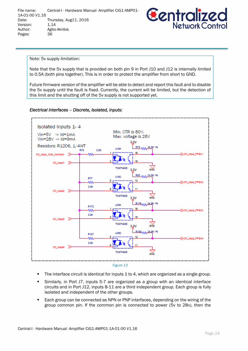
Electrical interfaces – Discrete, Isolated, inputs:
Figure 13
The interface circuit is identical for inputs 1 to 4, which are organized as a single group.
Similarly, in Port J7, inputs 5-7 are organized as a group with an identical interface
circuits and in Port J12, inputs 8-11 are a third independent group. Each group is fully
isolated and independent of the other groups.
Each group can be connected as NPN or PNP interfaces, depending on the wiring of the
group common pin. If the common pin is connected to power (5v to 28v), then the

File name: Central-I - Hardware Manual -Amplifier CiG1-AMP01-
1A-01-00 V1.16
Date: Thursday, Aug11, 2016
Version: 1.14
Author: Agito-Akribis
Pages: 36
Central-I - Hardware Manual -Amplifier CiG1-AMP01-1A-01-00 V1.16
Page 25
inputs of this group can be used with external NPN devices (external current sinking
devices). If the common is connected to the GND of some external power, then the
inputs can be used with external PNP devices (external current sourcing devices).
Note that the input circuit of the opto couplers includes two diodes. This enables the
usage as NPN of PNP.
Clearly, one group can be wired to interface external NPN devices and another group
can be wired to interface PNP devices. However, within a group, all interfaces should
be the same, as they are based on the connection of the group common pin
Sample – Connection for Digital IO
Here we take the connection of limit switches to digital input as example

File name: Central-I - Hardware Manual -Amplifier CiG1-AMP01-
1A-01-00 V1.16
Date: Thursday, Aug11, 2016
Version: 1.14
Author: Agito-Akribis
Pages: 36
Central-I - Hardware Manual -Amplifier CiG1-AMP01-1A-01-00 V1.16
Page 26
Electrical interfaces – Analog inputs:
Figure 14
Figure 15
The electrical interfaces of analog input 2 is identical to those of analog input 1.
The analog inputs are -12v to +12v, 12 bits.
Input circuit drawing is quite complex, in order to optionally support variety of analog
input sources. However, default assembly (see black mark) is for standard differential
analog input, with a simple input circuit, having an input resistance of ~60K ohms.
Input circuit bandwidth: 1KHz, -40 dB/dec.
For dedicated (non-differential) analog input formats, as shown in the above table, or
for any other type, please consult designer for dedicated hardware variants of the
product.
The software provides parameters to control the analog input reading, as follows:
Filter.
Offset.
File name: Central-I - Hardware Manual -Amplifier CiG1-AMP01-
1A-01-00 V1.16
Date: Thursday, Aug11, 2016
Version: 1.14
Author: Agito-Akribis
Pages: 36
Central-I - Hardware Manual -Amplifier CiG1-AMP01-1A-01-00 V1.16
Page 27
Dead band.
Gain.

File name: Central-I - Hardware Manual -Amplifier CiG1-AMP01-
1A-01-00 V1.16
Date: Thursday, Aug11, 2016
Version: 1.14
Author: Agito-Akribis
Pages: 36
Central-I - Hardware Manual -Amplifier CiG1-AMP01-1A-01-00 V1.16
Page 28
Amplifier – J7– I/O Port
This section describes the details of three I/O Ports J10 and J12.
Figure 16 I/O Port 2
Description: The graph above is about the second IO port on the amplifier board.
Manufacturer: Samtec Inc
P/N (product side): IPL1-107-01-L-D-RA-K
Cable connector P/N: IPD1-07-D-K
Crimp P/N: CC79L-2630-01-L
Other options are possible; please, consult with the manufacturer.
Pinout for J7 (I/O Port 2) is described below.
Pin #
Name Type Description
1 Vin_24V_IO_RTN PWR -OUT IO Power Return
2 Vin_24V_IO PWR -OUT 24V IO Power
3 OC_Output1 OUT Discrete, isolated, output 1 (programmable sink or
source)
4 OC_Output_123_Common_Power PWR - IN Common power pin for discrete, isolated, outputs 1 to 3
5 OC_Input6 IN Discrete, isolated, input 6 (NPN or PNP, depending on
connection of the common pin of this group)
6 OC_INPUT_567_Common IN Common power pin for discrete, isolated, inputs 5 to 7
J7
Pin 1
Pin 8
Pin 7
Pin 14

File name: Central-I - Hardware Manual -Amplifier CiG1-AMP01-
1A-01-00 V1.16
Date: Thursday, Aug11, 2016
Version: 1.14
Author: Agito-Akribis
Pages: 36
Central-I - Hardware Manual -Amplifier CiG1-AMP01-1A-01-00 V1.16
Page 29
Pin #
Name Type Description
7 DIF_IO_P IN Differential IO positive input (Also support single ended)
8 GND_EARTH PWR Ground-earth connection
9 OC-Output3 OUT Discrete, isolated, output 3 (programmable sink or
source
10 OC-Output2 OUT Discrete, isolated, output 2 (programmable sink or
source)
11 OC_Output_123_Common_Return PWR - IN Common power return pin for discrete, isolated, outputs
1 to 3
12 OC_Input7 IN Discrete, isolated, input 7 (NPN or PNP, depending on
connection of the common pin of this group)
13 OC_Input5 IN Discrete, isolated, input 5 (NPN or PNP, depending on
connection of the common pin of this group)
14 DIF_IO_N IN Differential IO negative input (Also support single
ended)

File name: Central-I - Hardware Manual -Amplifier CiG1-AMP01-
1A-01-00 V1.16
Date: Thursday, Aug11, 2016
Version: 1.14
Author: Agito-Akribis
Pages: 36
Central-I - Hardware Manual -Amplifier CiG1-AMP01-1A-01-00 V1.16
Page 30
Electrical interfaces – Discrete, Isolated, outputs:
Figure 17
The interface circuit is identical for outputs 1 to 3.
Each output can be programmed (by a software parameter) to act as a current sourcing
output (up to 300mA) or as a current sinking output (up to 500mA).
Common power is shared by all 3 outputs.
Common power can go up to 45 volts. Yet, typical usage should be limited by 36v.

File name: Central-I - Hardware Manual -Amplifier CiG1-AMP01-
1A-01-00 V1.16
Date: Thursday, Aug11, 2016
Version: 1.14
Author: Agito-Akribis
Pages: 36
Central-I - Hardware Manual -Amplifier CiG1-AMP01-1A-01-00 V1.16
Page 31
Amplifier – J11 - Static brakes
Figure 18
Description: The graph above is about the static brakes port on the amplifier board.
Manufacturer: Samtec Inc
P/N (product side): IPL1-102-01-L-D-RA-K
Cable connector P/N: IPD1-02-D-K
Crimp P/N: CC79L-2630-01-L
Other options are possible; please, consult with the manufacturer.
Pin #
Name Type Description
1 Static_Brake_High PWR
Static brake output for motor . Open-drain output with built-in
flyback diode to the Brake_Power for direct connection into
inductive load. Up to 3A operation.
2 Brake_Power PWR – IN Power supply for the brake isolated circuits in the controller. Up
to 48vDC.
3 Brake_Power_RTN PWR Return pin for the Brake_Power.
4 NC (Not Connected) NC This pin is unused
Note – Static Brake not supported yet:
The Central-I controller firmware does not support the operation of the static brake outputs
yet. This feature will be added soon, without any hardware change.
Pin 2 Pin 1
Pin 4 Pin 3

File name: Central-I - Hardware Manual -Amplifier CiG1-AMP01-
1A-01-00 V1.16
Date: Thursday, Aug11, 2016
Version: 1.14
Author: Agito-Akribis
Pages: 36
Central-I - Hardware Manual -Amplifier CiG1-AMP01-1A-01-00 V1.16
Page 32

File name: Central-I - Hardware Manual -Amplifier CiG1-AMP01-
1A-01-00 V1.16
Date: Thursday, Aug11, 2016
Version: 1.14
Author: Agito-Akribis
Pages: 36
Central-I - Hardware Manual -Amplifier CiG1-AMP01-1A-01-00 V1.16
Page 33
Electrical interfaces – static brakes:
Figure 19 Circuit Diagram

File name: Central-I - Hardware Manual -Amplifier CiG1-AMP01-
1A-01-00 V1.16
Date: Thursday, Aug11, 2016
Version: 1.14
Author: Agito-Akribis
Pages: 36
Central-I - Hardware Manual -Amplifier CiG1-AMP01-1A-01-00 V1.16
Page 34
Amplifier– Communication Port
Figure 20 Communication Port
Description: CONNECTOR, RJ45, PLUG, 8P8C, 1 PORT Manufacturer: TE
P/N (product side): 5-554720-2 Cable: CAT5
Note:
1. The J11/J12 connectors are communication unit connectors and J13/J14 are
mechanical connectors.
2. All of them are used to connect with another PCB board— CIGI-COM01-1A-02-01 to
realize the communication between the master controller CIG1-MAS and the product.
(The details of the board can be referred to in the hardware manual of CIGI-COM01-1A-
02-01)
3. The RJ45 connector is between the two connectors to communicate with the master
controller CIG1-MAS product variants via the Central-I Protocol
File name: Central-I - Hardware Manual -Amplifier CiG1-AMP01-
1A-01-00 V1.16
Date: Thursday, Aug11, 2016
Version: 1.14
Author: Agito-Akribis
Pages: 36
Central-I - Hardware Manual -Amplifier CiG1-AMP01-1A-01-00 V1.16
Page 35
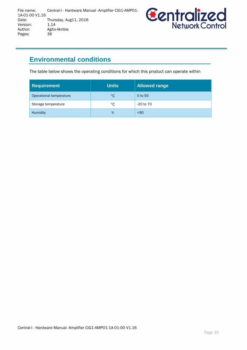
Environmental conditions
The table below shows the operating conditions for which this product can operate within
Requirement Units Allowed range
Operational temperature C 0 to 50
Storage temperature C -20 to 70
Humidity % <90
File name: Central-I - Hardware Manual -Amplifier CiG1-AMP01-
1A-01-00 V1.16
Date: Thursday, Aug11, 2016
Version: 1.14
Author: Agito-Akribis
Pages: 36
Central-I - Hardware Manual -Amplifier CiG1-AMP01-1A-01-00 V1.16
Page 36
References
[1] Central-i PN SN Definitions 6 March 2016.docx, 06-03-2016, V1.3


![ə book 1A busy 1A ě ə ť · f2f Pre-intermediate worldlist Czech.xls already 1A [ɔlred.i] už; již auxiliary 1A [ɔ zil.i.ər.i] pomocný book 1A [bυk] kniha; svazeček; rezervovat;](https://img.dokumen.tips/doc/110x75/5e828b38406837044e0d8c8f/-book-1a-busy-1a-f2f-pre-intermediate-worldlist-czechxls-already-1a.jpg)