Embed Size (px)
Citation preview

INDEX
ITEM PAGEBLOWERS
Double Inlet . . . . . . . . . . . . . . . . . . . . . . .47Duct Blower . . . . . . . . . . . . . . . . . . . . . .23General Industrial —Material handling . . . . . . . . .26, 27, 34, 35General Purpose-utility . . . . . .28 thru 33Pressure . . . . . . . . . . . . . . . . . . . . . .27, 34PVC-Corrosion Resistant . . . . .36, 37, 38Supply or Make-Up (Roof Top) . . . .23, 45
FANSAttic . . . . . . . . . . . . . . . . . . . . . . . . . . . . .11Bathroom . . . . . . . . . . . .15, 16, 18, 19, 20Ceiling . . . . . . . . . . . . . . . . . . . . . . . . . . .20Dryer Booster . . . . . . . . . . . . . . . . . . . . .21Duct-In Line . . . .16, 17, 20, 22, 23, 24, 25Exhaust, prop. . . . . . . . . . . . . . . .4, 5, 6, 7Kitchen . . . . . . . . . . . . . .16, 18, 19, 42, 43Roof, axial up-blast . . . . . .BACK COVER
centrifugal up-blast . . . . . . . .42, 43, 44centrifugal . . . . . . . . . . . . .16, 17, 40, 41
Sidewall, centrifugal . . . . . .16, 42, 43, 44U.L., NFPA 96 APPROVED . . . . . . . .42, 43
OTHERChemical resistance data . . . . . . . . . . .38Curbs, roof . . . . . . . . . . . . . . . . . . . .40, 46Draft inducers, duct boosters . . . . .12, 13Make-up air fans . . . . . . . . . . . .14, 23, 45Motor & fan controls . . . . . . . . . . . . . . .10Relief-Supply vents . . . . . . . . . . . . . . . .46Shutters & louvers . . . . . . . . . . . . . . . .8, 9Static vents . . . . . . . . . . . . . . . . . . . . .9, 46Thermostats . . . . . . . . . . . . . . . . . . . . . .10Variable Frequency Drives . . . . . . . . . .10Vibration Isolators . . . . . . . . . . . . . . . . .39
General Ventilation Info . . . . . . . . . . . . . . .2General Motor Info . . . . . . . . . . . . . . . . . . . .3
CALL FOR PRICING.Wholesale, distributor and OEM discounts are quoted on request.TERMS: Net 30 DaysFREIGHT: F.O.B. Medford, MAGUARANTEE: ONE YEARagainst defects in material or workman-ship. We do not assume any responsibilityfor incidental or consequential damages.Details of terms and conditions; and limita-tions of warranty and liability available onrequest.
ALL ITEMS SHOWN IN THIS CATALOG ARECARRIED IN STOCK FOR IMMEDIATE DELIVERY
MANUFACTURERS OF
CENTRAL-AIRE®
Exhaust FansFROM 8 TO 60 INCHES WITH SAFETY GUARDS
STOCKING DISTRIBUTOR FORACME FANTECH PEERLESSBROAN FASCO TJERNLUNDCOOLAIR LAU VIBRATION MTGSDELHI NEW YORK AND OTHERS
REPLACEMENT PARTSFan Blades Electric MotorsBlower Wheels Blower Shafts & BearingsBelts Pulleys
Fans & Blowers Repaired
We specialize in engineering practical solutionsto all ventilating problems.
Call direct to our engineering staff:Phone: (781) 393-4456
1-800-937-4326Fax: (781) 396-4581www.centralfan.com
CENTRALFAN CO.
3890 MYSTIC VALLEY PARKWAY, MEDFORD, MA 02155PHONE: (781) 393-4456
1-800-937-4326FAX: (781) 396-4581
ALL EQUIPMENT IS COMPLETELY ASSEMBLED AND TESTED BEFORE SHIPPING
NEW ENGLAND’S LARGEST
CATALOG #38PRICE $3.00
Central Fan Catalog_2013_Central Fan Catalog 1/28/13 1:25 PM Page 1

CATALOG #38www.centralfan.com
CENTRAL FAN CO., INC.3890 MYSTIC VALLEY PKWY.
MEDFORD, MA 02155PHONE: (781) 393-4456
1-800-937-4326FAX: (781) 396-45812
GENERAL INFORMATIONASSUME: Air @ sea level (.075 lb/ft3), 70°F, 50% RH, 29.92 in. Hg. This is STP condition.
MOTOR RPM CHANGES & HP REQUIRED1750 to 3500 RPM = 8 x HP1140 to 1750 RPM = 3.6 x HP850 to 1140 RPM = 2.4 x HP
NOISE, SOUND RATINGS, & SONESTypical Sound Levels
Sones dB Source
140 500,000 CFM blower
120 Threshold of feeling
150 110 15,000 CFM blowerelevated train; chipping hammer,loud street noise
90 90* Noisy factory; highway auto
38 80 Shouting; noisy gathering
10 60 Average factory; Average restaurant
9 50 Average office
1 40 Quiet home: average auditoriumQuiet conversation
30 Whisper
10 Sound proof roomThreshold of human audibility
0
*Max. permissible noise per 8 hr.-day
Although fan noise is a function of a multitude of factorsthe principal sources are (a) air turbulence (b) mechanicaland (c) vibration. Generally the quietest fan is also the mostmechanically efficient. Because a given fan location charac-teristics dictate audible noise, fan dBA cannot be guaran-teed. However, relative noise levels of fans can be suitablefor considering one fan versus another.
The SONE number used in this catalog is a mathemati-cally derived loudness (sound pressure) value as heard bythe human ear 5 feet from the inlet of the noise source in freeair (no ducts). Under these conditions, 10 SONES is twice asloud as 5 SONES; or 20 SONES is 1/2 as loud as 40SONES. Thus, SONE NUMBERS can be used as guides forfan selection.
Where noise is a critical factor a more detailed, scientif-ic analysis of the noise source and its surroundings would bedesirable. However, lined ducts, especially near the fan, pro-vide ample sound attenuation for most clean air situations.Also, to double the loudness (SONES) of a given fan, 13more of the same fan must be added.
Recommended Ventilation RequirementsMax. occupantLoad, (persons CFM
Classification per 1000ft.2) per personor area
Education
Auditorium 150 15
Classroom 50 15
Locker Room 0.5 cfm/ft.2
Training Shops 0.5 cfm/ft.2
Restaurant
Lounge 100 30
Dining Room 70 15
Offices
Conference Room 50 20
Office Space 7 20
Reception 60 20
Public Spaces
Locker Rooms 0.5 cfm/ft.2
Public Restrooms 50 cfm/closet
or urinal
Parking Garage 0.75 cfm/ft.2
Smoking Lounges 70 60
Specialty Shops
Auto Service Stations 1.5/ft.2
Beauty Salons 0.6 cfm/ft.2
Clothing Stores 0.30 cfm/ft.2
Nail Salons 0.6 cfm/ft.2
Pet Shops 1.0 cfm/ft.2
Supermarkets 8 15
Hazardous Locations
Battery Charging Room 1.0 cfm/ft.2
Crawl Space 0.2 cfm/ft.2
Electrical Room 0.6 cfm/ft.2
Flammable & Combustible Materials 1.0 cfm/ft.2
150 cfm min.
Gas Storage Rooms 1.0 cfm/ft.2
Hazardous Material Storage 1.0 cfm/ft.2
Sports & Facilities
Ball Rooms 100 25
Gymnasiums 30 20
Ice Rinks 0.5 cfm/ft.2
Swimming Pools 0.5 cfm/ft.2
Workrooms
Darkrooms 1.0 cfm/ft.2
Duplicating, Printing 0.5 cfm/ft.2
BASIC FAN LAWSVolume varies directly
New CFM = Old CFM xNew RPM
as speed: Old RPMHorsepower varies as
New HP = Old HP xNew RPM
cube of speed: Old RPMPressure varies as
New SP = Old SP xNew CFM
square of volume: Old CFMHorsepower varies as
New HP = Old HP xNew CFM
cube of volume: Old CFM( )
VENTILATION OF HOODS & BOOTHSCapture
Process Type of Hood VelocityFPM
Canopy Hood 75–250Kitchen Ranges Island Hood 100–150
Updraft 200–250
Plating Tanks Canopy Hoods 150–250Slotted Sides 1500–2000
Steam Tanks Canopy Hood 75–150
Paint Spraying Open Front Booth 100
Furnaces Canopy Hood 100–200Enclosed Booth 150–250
Laboratory Booth Open Front Booth 75–125
KITCHEN RANGE HOODS1. CFM required is length x width (in feet) x velocity
as per above table.(Depth of hood does not enter into calculations)
2. Hood should extend approximately 12 inchesbeyond front and sides of range. Depth shouldbe two feet or more to accommodate bursts ofsmoke.
3. Duct velocity can be 500 to 2000 FPM.4. Two smaller ventilators are recommended in
place of one for more flexible operation and alsoto provide ventilation should one fan fail.Recommended ventilators for kitchen rangehoods are radial blade and backward curveblowers.
5. U.L. classification YZHW and NFPA 96 providemore detail.
VELOCITY PRESSURES(At Std. Density .075#/Ft.3)
VEL. VP VEL. VPFPM In. Water FPM In. Water1800 .202 4400 1.212000 .249 4600 1.322200 .302 4800 1.442400 .359 5000 1.562600 .421 5200 1.692800 .489 5400 1.823000 .561 5600 1.963200 .638 5800 2.103400 .721 6000 2.243600 .808 6200 2.403800 .900 6400 2.724000 .998 6600 2.724200 1.10 6800 2.88
STATIC PRESSURE LOSSES (in. H2O)No. of Duct Length Grease FilterElbows 10' 20' 30' 2" Mesh Baffle
0 .13 .17 .21 .25 .551 .31 .35 .39 .25 .552 .49 .53 .57 .25 .55
Based on average duct velocity of 1700 FPM.
SUPPLY OR MAKE-UP AIRUnnecessary loss of summer air conditioningor winter heating can be avoided if 80-90% ofexhaust air is supplied at or near the exhausthood. Make-up air appropriately introducedinto the exhaust hood need not be treated.
( )( )( )
ROOM SONES dBA CORRELATION
Sound Level dBA
Loud
ness
, Son
es
3
2
3
Central Fan Catalog_2013_Central Fan Catalog 1/28/13 1:25 PM Page 2

CATALOG #38www.centralfan.com
CENTRAL FAN CO., INC.3890 MYSTIC VALLEY PKWY.
MEDFORD, MA 02155PHONE: (781) 393-4456
1-800-937-4326FAX: (781) 396-4581 3
TYPE OF MOTOR USUALLY REQUIREDThe great majority of small motors (1⁄2 HP & smaller) are 115 volts
single phase.
Sizes of 3⁄4 to 11⁄2 are fairly divided between 208/230 volts singlephase and 208 to 550 volts 3 phase.
Sizes of 2 HP and larger are generally three phase as they are lessexpensive and less troublesome than single phase motors.
MOTOR INFORMATION
NEMA MOTOR FRAME DIMENSIONS-INCHESHP 1750 U D V 2F 2E BA
3500 1750 Frame Shaft Shaft Shaft Parallel Across To FirstRPM RPM Size* Dia. Height Len. To Shaft Shaft Bolt Hole
1⁄20 42 3⁄8 25⁄8 11⁄8 13⁄4 31⁄2 slot 21⁄161⁄8-1⁄2 1⁄12-1⁄3 48 1⁄2 3 11⁄2 23⁄4 41⁄4 slot 21⁄23⁄4-2 1⁄2-11⁄2 56 5⁄8 31⁄2 17⁄8 3 47⁄8 slot 23⁄411⁄2 1 143T 7⁄8 31⁄2 21⁄4 4 51⁄2 21⁄43 2 145T 7⁄8 31⁄2 21⁄4 5 51⁄2 21⁄45 3 182T 11⁄8 41⁄2 23⁄4 41⁄2 71⁄2 23⁄4
5-71⁄2 5 184T 11⁄8 41⁄2 23⁄4 51⁄2 71⁄2 23⁄410 71⁄2 213T 13⁄8 51⁄4 33⁄8 51⁄2 81⁄2 31⁄215 10 215T 13⁄8 51⁄4 33⁄8 7 81⁄2 31⁄220 15 254T 15⁄8 61⁄4 4 81⁄4 10 41⁄425 20 256T 15⁄8 61⁄4 4 10 10 41⁄430 25 284T 17⁄8 7 41⁄2 91⁄2 11 43⁄440 30 286T 17⁄8 7 41⁄2 11 11 43⁄4
Frames without ‘T’ (preceding smaller size shaft). *3500 RPM motors are smaller.
APPROXIMATE MOTOR AMPS-1750 RPM1 Phase 3 Phase
HP 115V 230V 200V 230V 460V 575V1⁄6 3.0 1.5 .9 .8 .40 .321⁄4 4.0 2.0 1.1 1.0 .50 .401⁄3 5.2 2.6 1.6 1.4 .70 .561⁄2 7.0 3.5 2.3 2.0 1.0 .803⁄4 10.4 5.2 3.2 2.8 1.4 1.1
1 13.0 6.5 4.3 3.8 1.9 1.511⁄2 19.0 9.5 5.7 5.0 2.5 2.02 24.0 12.0 7.1 6.2 3.1 2.5
3 34.0 17.0 10.8 9.4 4.7 3.85 52.0 26.0 16.0 14.0 7.0 5.671⁄2 76.0 38.0 24.0 21.0 11.5 8.4
10 90.0 45.0 30.0 26.0 13.0 10.0
15 46.0 40.0 20.0 16.020 57.0 50.0 25.0 20.025 76.0 66.0 33.0 26.030 85.0 74.0 38.0 30.0
For 3600 RPM motors multiply by .90 *60 HertzFor 1140 RPM motors multiply by 1.1
Starting amps are approximately five times running amps. Fusesmust be large enough to carry this current. Delayed action fuses of only25% above rated current may be substituted for better protection.
NEMA VOLTAGE VARIATIONSNameplate
Rating Suitable for line voltages
200/400 208,220 or 440
220/440 208,220,230 or 440,460
230/460 208,220,230,240 or 440,460,480
550 or 575 550 to 600
NEMA ratings are plus or minus 10% of nameplate. *60 Hertz
Variations are suitable for fan or blower duty or other easy to startapplications only.
EFFECT OF VOLTAGE IMBALANCEA small voltage imbalance between phases will cause an abnormal
temperature rise and abnormal current. For example, temperature ¤t will rise 6-10 times the voltage difference. Notify the power com-pany if voltage exceeds 1% (2 volts at 200v).
Follow all local electrical and safety codes, as well as the NationalElectrical Code (NEC) and the Occupational Safety and Health Act(OSHA).
*
*
Central Fan Catalog_2013_Central Fan Catalog 1/28/13 1:25 PM Page 3

CATALOG #38www.centralfan.com
CENTRAL FAN CO., INC.3890 MYSTIC VALLEY PKWY.
MEDFORD, MA 02155PHONE: (781) 393-4456
1-800-937-4326FAX: (781) 396-45814
CENTRAL-AIRE® Model K Exhaust FansHEAVY DUTY-GENERAL PURPOSE-DIRECT DRIVE-ENCLOSED MOTOR
Quiet operating general purpose fans for ventilation of most small areas where the usual low pressureconditions exist. For long duct runs use a centrifugal blower.Suitable for use in restaurants, bars, clubs, laundries, bakeries, barns, stores, offices, industrial plants andelectronic equipment cooling.
Moderately priced and economical in operation-Built for years of dependable service-Broad deep pitchblades for quiet, high air delivery-Attractive design, Gray green finish. Quality is equal or superior to high-er priced fans.
• Thermally protected motors • Variable speed operation some models• Ball and sleeve bearings • Aluminum fan blades• OSHA type wire guards • 125°F max. temp. of operation
Available with reverse air flow (suction type) at no extra charge.Suitable for operation to 125°F—Over 125°F use a centrifugal blower
MODEL K-SINGLE PHASE-115 VOLTS•
Variable APPROXIMATE CFMModel 1 Speed Speed Wall 115 v. Speed Static Pressure (inches H2O) ShipNo. HP S V Shutter Amps RPM 0 .1 1⁄8 1⁄4 3⁄8 1⁄2 5⁄8 Wt.
*K80 1⁄80 X X A8 .6 1550 300 220 190 100 – 7*K10 1⁄40 X X A10 1.0 1550 600 500 450 300 210 12
*K12 1⁄20 X X A12 1.4 1550 1000 920 880 700 450 15*K14 1⁄15 X X A14 2.1 1100 1500 1300 1200 1000 720 20
*K161⁄6
X XA16
2.8 11602000 1860 1800 1560 1330
28*KB16 X — 2.4 1160 30
*K181⁄4
X —A18
4.9 11602900 2660 2570 2340 2100
29*KB18 X — 3.8 1160 32
*KB20 1⁄4 X — A20 3.8 1160 3600 3400 3330 3000 2700 35
*KB24 1⁄2 X — A24 6.5 1160 5800 5500 5200 4600 3700 51
*115/208-230v 1Ø (Ball Bearing) (v) Variable speed includes Solid State Control (X) Available Model •See p.5 for 3Ø Exhaust fans
ACCESSORIES:Motorized shutter Chemical resistant coating fanChemical resistant coating shutter
General purpose exhaust fansfor most small areas.
IMMEDIATE DELIVERY
Dimensions (inches)Model Shutter Min. HoleNo. A B** C D Round*
K8 101⁄2 5 0 111⁄4 8K10 13 51⁄2 0 13 10
K12 16 71⁄2 3⁄4 15 14K14 18 8 3⁄4 17 16
K16 20 11 1 19 18KB16 20 13 1 19 18
K18 22 105⁄8 1 21 20KB18 22 13 1 21 20
KB20 24 13 1 23 22
KB24 30 13 11⁄2 27 26
Model number indicates fan blade diameter
*Fan and shutter mount over the hole
**Add 2" for suction fan configuration
ExhaustAir Flow
Reverse (suction) air flow requiresmotorized shutter with #C10 switch
See page 8
See
Pag
e 5
For
Fan
s In
Thi
sS
tatic
Pre
ssur
e R
ange
Central Fan Catalog_2013_Central Fan Catalog 1/28/13 1:25 PM Page 4
CATALOG #38www.centralfan.com
CENTRAL FAN CO., INC.3890 MYSTIC VALLEY PKWY.
MEDFORD, MA 02155PHONE: (781) 393-4456
1-800-937-4326FAX: (781) 396-4581 5
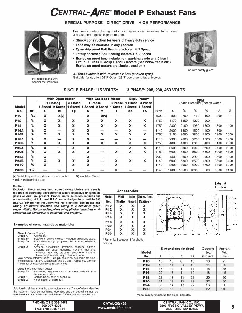
Dimensions (inches) Opening Approx.Model Nec. Wt.No. A B C D (Round) (Lbs.)
P10 13 10 0 13 10 25P12 16 11 3⁄4 15 14 30P14 18 12 1 17 16 35P16 20 13 1 19 18 45
P18 22 13 11⁄2 21 20 50P20 24 13 11⁄2 23 22 60P24 30 14 11⁄2 27 26 80P30 36 15 2 33 32 110
Model number indicates fan blade diameter.
CENTRAL-AIRE® Model P Exhaust FansSPECIAL PURPOSE—DIRECT DRIVE—HIGH PERFORMANCE
Features include extra high outputs at higher static pressures, larger sizes, 3 phase and explosion proof motors.
• Sturdy construction for years of heavy duty service• Fans may be mounted in any position• Open drip proof Ball Bearing motors-1 & 2 Speed• Totally enclosed Ball Bearing motors-1 & 2 Speed• Explosion proof fans include non-sparking blade and Class I
Group D, Class II Group F and G motors (See below “caution”)Explosion proof motors are single speed only
All fans available with reverse air flow (suction type).Suitable for use to 125°F-Over 125°F use a centrifugal blower.For applications with
special requirements
Fan with safety guard.
Class I (Gases, Vapors)Group A- Acetylene.Group B- Butadiene, ethylene oxide, hydrogen, propylene oxide.Group C- Acetaldehyde, cyclopropane, diethyl ether, ethylene,
isoprene.Group D- Acetone, acrylonitrile, ammonia, benzene, butane,
ethylene dichloride, gasoline, hexane, methane,methanol, naphtha, propane, propylene, styrene,toluene, vinyl acetate, vinyl chloride, xylene.
Note: A motor rated for Class I, Group D should not be used in the pres-ence of Group A,B or C substances; and a Class II, Group F & G motorshould not be used with Group E substances.
Class II (Combustibles Dusts)Group E- Aluminum, magnesium and other metal dusts with sim-
ilar characteristics.Group F- Carbon black, coke or coal dust.Group G- Flour, starch or grain dust.
Examples of some hazardous materials:
Additionally, all hazardous location motors carry a “T code” which identifiesthe maximum motor surface temp. (operating and burnout) which must becorrelated with the “minimum ignition temp.” of the hazardous substance.
SINGLE PHASE: 115 VOLTS‡ 3 PHASE: 208, 230, 460 VOLTS
With Open Motor With Enclosed Motor Expl. Proof* CFM1 Phase‡ 3 Phase 1 Phase 3 Phase 1 Phase 3 Phase Static Pressure (inches water)
Model 1 Speed 2 Speed 1 Speed 1 Speed 2 Speed 1 Speed 1 Speed 1 SpeedNo. HP S M T‡ S M T SX TX RPM 0 1⁄8 1⁄4 3⁄8 1⁄2 5⁄8
P10 1⁄25 X X(v) — X X(v) — — — 1500 800 700 480 400 300 –0
P12 1⁄6 X X X X X X X X 1750 1470 1350 1200 900 –0 –0
P14 1⁄4 X X X X X X X X 1750 2300 2100 1950 1600 1500 1400
P16A 1⁄8 X — X X — — X — 1140 2000 1800 1500 1100 800 –0P16B 1⁄3 X X X X X X X X 1750 3150 3050 2800 2600 2300 2000
P18A 1⁄6 X — X X — — X — 1140 2900 2600 2200 1700 1500 1300P18B 1⁄2 X X X X X X X X 1750 4300 4000 3800 3400 3100 2800
P20A 1⁄4 X — X X — — X X 1140 3600 3300 3000 2700 2400 2000P20B 3⁄4 X X X X — X X X 1750 6000 5800 5600 5300 5000 4700
P24A 1⁄2 X — — X — — — — 800 4800 4600 3900 2900 1800 1000P24B 1⁄2 X X X X — X X X 1140 6000 5800 5500 4500 3800 3400P24C 3⁄4 X — X X — X — — 1140 8000 6900 6200 5700 5500 5000
P30B 11⁄2 — — X — — X — — 1140 11000 10500 10000 9500 9000 8100
(v) Variable speed includes solid state control (X) Available Model
*Incl. Non-sparking blade
Caution:Explosion Proof motors and non-sparking blades are usuallyrequired in operating environments where explosive or ignitablegases or dust are present. Proper motor selection requires fullunderstanding of U.L. and N.E.C. code designations. Article 500(N.E.C.) covers the requirements for electrical equipment andwiring. Equipment selection and wiring is a customer (user)responsibility. Motors and impellers misapplied in hazardous envi-ronments are dangerous to personnel and property.
Model Wall Inlet Chem. Res.No. Shutter Guard Coating*P10 X X XP12 X X XP14 X X XP16 X X X
P18 X X XP20 X X XP24 X X XP30 X X X
*Fan only. See page 8 for shutter coating.
Accessories:
Central Fan Catalog_2013_Central Fan Catalog 1/28/13 1:25 PM Page 5

CATALOG #38www.centralfan.com
CENTRAL FAN CO., INC.3890 MYSTIC VALLEY PKWY.
MEDFORD, MA 02155PHONE: (781) 393-4456
1-800-937-4326FAX: (781) 396-45816
CENTRAL-AIRE® Model R Exhaust FansALL PURPOSE—BELT DRIVE—RUGGED WELDED CONSTRUCTION
All Purpose-Belt Drive-Rugged Welded ConstructionAn all purpose high performance fan suitable for ventilation of most large areas requiring dependable ventilation.Large selection of speeds and motors to choose from to cover a wide range of commercial and industrial requirements.Recommended for ventilation of stores, halls, offices, restaurants, garages, barns, air conditioning equipmentrooms and all types of industrial buildings.Moderately priced yet built for years of dependable service.
IMPORTANT FEATURES• Quiet operation-High air output-Slow speed.• Flexible choice of speeds and motors available.• Easy and economical motor replacement if necessary.• Ball Bearing throughout-motor & fan.• Generously sized belt drive for trouble free operation.• Heavy duty propellers, designed for low static and high air volume…either exhaust or suction.• Not designed for motor reversing operations.
All purpose exhaust fansfor most large areas.
WITH OPEN MOTOR-WHEN ORDERING: SPECIFY LINE VOLTAGE AND PHASESingle Phase Three Phase Approx. Tip CFM
1 Speed 2 Speed 1 Speed 2 Speed Wall Fan Speed Noise Static Pressure (inches water)Model HP S M T R Shutter RPM FPM Rating 0 1⁄8 1⁄4 3⁄8 1⁄2 5⁄8
B 1⁄4 X X X – 540 3390 A 4800 3900C* 1⁄3 X X X – 600 3770 A 5300 4600 3100D 1⁄2 X X X X A24 690 4335 B 6000 5400 4300 2800E 3⁄4 X X X X 750 4710 C 7000 6400 5600 3800 3100F 1 X X X X 850 5300 D 8000 7500 6800 5400 4300 3600
C 1⁄3 X X X – 460 3770 A 7000 5700D* 1⁄2 X X X X 480 4080 A 8000 6900 4600E 3⁄4 X X X X A30 530 4710 B 9000 8100 6500 4200F 1 X X X X 570 5100 C 10000 9200 8000 5400 4400G 11⁄2 X – X X 640 5890 D 12000 11300 10300 8200 6500 5300
D 1⁄2 X X X X 480 3770 A 10000 8200E* 3⁄4 X X X X 600 4712 B 12000 10300 6900F 1 X X X X A36 620 5655 B 14000 12600 10100 6400G 11⁄2 X – X X 700 6597 C 16000 14700 12800 8600 7100H 2 X – X X 760 7540 D 18000 17000 15500 12200 9800 7900
E 3⁄4 X X X X 400 3848 A 16000 13100F* 1 X X X X 480 4398 B 18000 15400 10400G 11⁄2 X – X X A42 520 5497 B 20000 18000 14400 9200H 2 X – X X 600 6322 C 22000 20200 17600 11900 9700J 3 X – X X 670 7147 D 25000 23500 21500 17000 13500 11000
F 1 X X X X 400 3770 A 21000 17200G* 11⁄2 X – X X 460 4712 B 24000 20600 13900H 2 X – X X A48 500 5684 B 26000 23400 16200 13200J 3 X – X X 580 6597 C 30000 27600 24000 16200 13200K 5 – – X X 650 8167 D 36000 33800 30900 24500 19500 16000
G 11⁄2 X – X X 300 4241 A 27000 23200 15600H* 2 X – X X
A54350 4948 B 30000 27000 21600 13800
J 3 X – X X 420 5655 B 35000 32200 28000 18900 15400K 5 – – X X 500 6361 C 42000 39500 36000 28500 22000 18500
H 2 X – X X 270 4271 A 34000 30600 24500 18600J* 3 X – X X
A60300 4712 B 41000 37000 32800 22100 18000
K 5 – – X X 375 5890 B 48000 45000 41000 34000 27000 22000L 71⁄2 – – X X 470 6744 C 55000 53000 49000 44000 38000 33000
*Recommended for most commercial and industrial applications. See page 10 for motor controls.(X) Available models
R24
R30
R36
R42
R48
R54
R60
WARNING:OSHA guards recommended
when installing fan within 7' of floor.
SEE page 7
SPECIFY EXHAUST OR SUCTION
NOISE RATINGApplications Rating
Residences, Churches, Schools, Libraries AStores, Offices, Hall, Restaurants A or BLaundries, Bakeries, Bowling Alleys B or CVery noisy locations B,C, D
Dimensions & Accessories: See next page
Central Fan Catalog_2013_Central Fan Catalog 1/28/13 1:25 PM Page 6

CATALOG #38www.centralfan.com
CENTRAL FAN CO., INC.3890 MYSTIC VALLEY PKWY.
MEDFORD, MA 02155PHONE: (781) 393-4456
1-800-937-4326FAX: (781) 396-4581 7
CENTRAL-AIRE® Model R Exhaust Fans
ACCESSORIESMotorized Chem. Resis. CoatingShutters Motor* Two**
Inlet 115 or Fan and Automatic Disconnect SpeedModel Guard 230 V #440V Motor Shutter Switch Controls
R 24 X X X X X X XR 30 X X X X X X XR 36 X X X X X X XR 42 X X X X X X X
R 48 X X X X X X XR 54 X X X X X X XR 60 X X X X X X X
# 440V uses 115/230V motor with a transformer.
* Mounted to fan panel.
** All without overload protection.
OSHA COMPLIANT FAN GUARD20 gauge galvanized steel panels, expanded metal grille. Bolt together guardsshipped unassembled (mounting hardware included). Heavy gauge panels bolttogether to form housing. Grille fastens to housing with screws supplied. Guardcan be mounted directly to fan frame or wall.
GUARD DIMENSIONSModel Depth ShipNo. A B C Wt.
R 24 30 30 20 35R 30 36 36 20 40R 36 42 42 30 60R 42 48 48 30 90
R 48 54 54 32 120R 54 60 60 34 200R 60 66 66 37 256
DIMENSIONS (INCHES)Panel Approx. Shutter Opening Min. Approx.
Model Sq. Depth (Sq.) Req. (Rd.) Wall Wt.No. A B* C D O* W** Lb.
R 24 30 14 11⁄2 27 26 6 70-100R 30 36 15 2 33 32 7 90-120R 36 42 16 21⁄4 39 38 8 100-140R 42 48 17 21⁄2 45 44 10 130-150
R 48 54 18 21⁄4 51 50 12 160-200R 54 60 27 2 57 56 14 270-320R 60 66 27 2 63 62 16 390-470
Model number indicates fan blade diameter.*Allows venturi penetration of wall.**Shutter blades will flutter if fan blade is too close to shutter.“W” dimension must be increased for higher RPM or where quieter operation is desired.
Central Fan Catalog_2013_Central Fan Catalog 1/28/13 1:25 PM Page 7

CATALOG #38www.centralfan.com
CENTRAL FAN CO., INC.3890 MYSTIC VALLEY PKWY.
MEDFORD, MA 02155PHONE: (781) 393-4456
1-800-937-4326FAX: (781) 396-45818
Model A Aluminum Wall ShuttersAUTOMATIC-MOTORIzED-CHAIN OPERATED
EXTRA HEAVY DUTY FRAMES FOR DIMENSIONAL STABILITY• Frame is .080 x 1.50 extruded aluminum with mill finish & welded corners.• Aluminum blades are 26 gauge with 20 gauge galvanized reinforcement strip across
top of blade & felt seal on leading edge of blade for quiet closing.• Stainless steel bearings and pivot pins for extended life.• POSITIVE ACTION MOTORIzED SHUTTERS: Motor is securely bolted to frame.
Special linkage operates center rod for uniform and positive operation.• CHAIN OPERATED: For manual operation; coil spring positive closing.* SPRING OPEN – POWER CLOSE For use in elevator rooms that require
venting with loss of power.
Nominal 2600 SpringDim. (Sq.) FPM Automatic Motorized Open
Model I.D. O.D. Max Gravity 115 or Chain PowerNo. A B CFM Operated 230 V. 440 ≠ Operated Close
A 8* 8 11 1150 X –. –. XA 10 10 13 1800 X X X X XA 12 12 15 2600 X X X X XA 14 14 17 3500 X X X X X
A 16 16 19 4600 X X X X XA 18 18 21 5850 X X X X XA 20 20 23 7200 X X X X XA 24 24 27 10400 X X X X XA 30 30 33 16250 X X X X X
A 36 36 39 23400 X X X X XA 42 42 45 31850 X X X X XA 48 48 51 41600 X X X X XA 54 54 57 52650 X X X XA 60 60 63 65000 X X X X
*Steel frame with 1 5⁄8 flange….this size only Maximum UPS ship size is A36, B36 ≠ 440V uses 115/230V motor with a transformer (X) Available models
Nominal To 1500O.D. FPM Automatic Motorized
Model +0 - 1⁄8 Max. Gravity 115 or #440VNo. (Square) CFM Operated 230 V.
B 9 9 800 X X XB 10 10 900 X X XB 12 12 1300 X X XB 14 14 1800 X X XB 15 15 2100 X X X
B 16 16 2400 X X XB 18 18 3100 X X XB 20 20 3900 X X XB 22 22 4800 X X XB 24 24 5700 X X XB 28 28 7800 X X X
B 30 30 9000 X X XB 32 32 10000 X X XB 36 36 13000 X X XB 39 39 15000 X X XB 42 42 17900 X X X
BS 18 20 3100 X – –BS 22 24 4800 X – –BS 26 28 7000 X – –BS 30 321⁄2 9000 X – –BS 37 391⁄2 14000 X – –
(X) Available models #440V use 115/230V motor with a transformer
DELAY SWITCH….MOUNTED ON SHUTTERMotorized shutter will not open against substantial fan induced air flow. Delay switch should beused to allow shutter to open fully before fan becomes operational. For 1Ø or 3Ø applications.
Delay Switch Model C10
PROTECTIVE COATING
.
Model B Roof Fan ShuttersFlange-less steel frame-Felted aluminum blades-Can be used inside ducts. Opens in direction of air flow. Curb drop in type toprevent backdraft when roof fan is not running. Sized to fit onto shelf of roof curb.
FRONT VIEWSIDE VIEWAIR FLOW
Model A MotorizedModel A
Air Dry PVC CoatingModels A,B or BS
Also available
Central Fan Catalog_2013_Central Fan Catalog 1/28/13 1:25 PM Page 8

CATALOG #38www.centralfan.com
CENTRAL FAN CO., INC.3890 MYSTIC VALLEY PKWY.
MEDFORD, MA 02155PHONE: (781) 393-4456
1-800-937-4326FAX: (781) 396-4581 9
Stock Nominal Intake ShipNo. Size* (in.) Free Area (ft2) CFM** Wt. Lbs.S61 12 x 12 0.33 260 9
S62 14 x 14 0.45 360 10
S63 16 x 16 0.60 480 12
S64 18 x 18 0.69 550 14
S66 24 x 24 1.52 1200 21
S67 30 x 30 2.66 2100 29
S68 36 x 36 4.12 3300 40
*Suggested hole size (Louver dimension w/o flange 1⁄4" less)
Max. single section 60" x 60". For larger sizes use multiple sections.
Other sizes and shapes, etc. Special Order
STATIONARY LOUVERS• Extruded .080” aluminum frame construction, with .063” blades.
• Drainable blades-falling water is drained to the side, removingcascading water droplets from the air stream.
• Mitered corners for dimensional stability.
• Expanded 3⁄4" screen interior mounted. (insect screen optional)
• 11⁄2" flange is standard (channel frame optional).
• Standard mill finish (optional Baked Enamel, Kynar, Anodized).
• 4" deep frame (6" Available).
CONTROL DAMPERS• Available in 13 ga. aluminum and 16 ga. steel
construction.
• Opposed blade and Parallel blade models.
• PVC foam gasketed blades.
• Low leakage models with stainless steel jam seals.
• Concealed end linkage.
• Wide variety of manual, electric or pneumatic operators and operator accessories.
• Custom made to order.
BACKDRAFT DAMPERS• .050 aluminum construction.
• Synthetic bearings.
• Vinyl blade seals.
• Full 90 degree operation.
• Flange and channel models available.
• Intake and exhaust installations.
• Vertical and horizontal models.
• Custom made to order maximum single size is 40" W x 48" H.
For larger sizes use multiple sections.
COMBINATION LOUVERS• Combination louvers integrate stationary blade and adjustable
blade construction in a single frame.
• All the features and options of stationary models.
• Blade edge gaskets.
• Rear mounted exposed linkage.
• Wide variety of manual, electric or pneumatic operators.
• Custom made to order maximum single size is 72" W x 96" H.
For larger sizes use multiple sections.
CUSTOM ORDER LOUVERS AND DAMPERS
IN STOCK SIZES
**max. cfm beforewater penetrationbegins (800 FPM).
Central Fan Catalog_2013_Central Fan Catalog 1/28/13 1:25 PM Page 9

CATALOG #38www.centralfan.com
CENTRAL FAN CO., INC.3890 MYSTIC VALLEY PKWY.
MEDFORD, MA 02155PHONE: (781) 393-4456
1-800-937-4326FAX: (781) 396-458110
INPUT POWER SAVING (RPM CONTROL)A significant reduction in energy consumption is realized when centrifugal fan
speeds are reduced only slightly. In applications where maximum demand volumeis not constant (VAV Systems), RPM control with inverters (variable frequency)could result in considerable reduction in power consumption. (Fan power demandvaries with RPM3)
Analysis of each fan application will determine the suitability of various volumecontrol methods (Dampers, inlet vanes & inverters). Inverters available special order.
Motor Controls for Fans & BlowersSINGLE SPEED CONTROLSMaximum HP Dimensions
Manual Cat. 208 460 NemaType No. Phase 115V 230 550 Size Poles Fig. H W D
Without 6810-G 1 2 2 – 1 2 A 4 21⁄4 21⁄2Overload 7810-GD 3 – 71⁄2 10 1 3 A 4 21⁄4 21⁄2Exp. Prf. 6810-E 1 1 2 – 00 1 B 63⁄4 31⁄2 43⁄4Exp. Prf. 7810-E 3 – 71⁄2 10 00 3 B 63⁄4 31⁄2 43⁄4
TWO SPEED CONTROLS
C61 1⁄3 1⁄3 – 00 1 C 41⁄4 21⁄2 2Without C62 1 3⁄4 3⁄4 – 00 2 C 41⁄4 21⁄8 23⁄8Overload 27940 1 1 – 00 2 C 41⁄4 23⁄4 21⁄2Protection JV2 3 – 3 3 1 3 D 8 3 31⁄2
JV5 (1 Wdg.) – 5 5 1 3 D 8 3 31⁄2
LINE VOLTAGE THERMOSTATS (1ø)Max HP Max Motor Amps Temp ºF Switch
Model Type 115V 230V 115V 230V Range Diff Type
C73 Heat/Cooling 3⁄4 11⁄2 13.8 10 50-90 2° SPSTC74 Cooling (Attic) 3⁄4 11⁄2 13.8 10 90-130 15° SPSTC74A Cooling (Attic) – – 4.4 – 50-120 15° SPSTC76A Heat/Cooling 3⁄4 11⁄2 13.8 10 40-110 3° SPDTC77* Heat/Cooling – – 16 8 30-110 3° SPDT/SPDT
MOTOR DISCONNECT SWITCHESSingle Phase Three Phase
HP 1 Sp. 2 Sp. 1 Sp. 2 Sp.3⁄4 X X X X1-2 X X X X3 X – X X5 – – X X
71⁄2-10 – – X* –
* 460V-550V only (X) Available
*2-stage (2speed or 2 motors).
Fig. A
Fig. B
Fig. C
Fig. D
SOLID STATE VARIABLECONTROL
(Shaded Pole or Perm. Cap. Motors)SINGLE PHASE
Model No. Volts AmpsC64 120 6C65 120 10C75 230 6277V 277 6C64-3 3-wire controlC65-3 for constant 115v( )
1/2 thru 3 Hp 230 Vac 1 Phase - 50/60 Hz
1/2 thru 15 Hp 230 Vac 3 Phase - 50/60 Hz
1/2 thru 30 Hp 460 Vac 3 Phase - 50/60 Hz
Applications: Variable torque, constant torque or constant horsepower applications. New installations,replacements and original equipment manufactures (OEM).
Features: Volts per Hertzs or Sensorless Vector Control with peak overload capacity of 150% and PIDcapability. Flexible mounting options with IP20 enclosure as standard and NEMA 1 option kit. Removablekeypad with operator interface and local speed control. Programming by Groups makes it easy to navigateand find parameters. A quick start assistant enables users to program and start using the drive in minuteswithout need for a User Manual. Built-in braking transistor allows connection to remote braking resistor forenhanced performance needs.
ACB330AC Micro Drive
Central Fan Catalog_2013_Central Fan Catalog 1/28/13 1:25 PM Page 10

CATALOG #38www.centralfan.com
CENTRAL FAN CO., INC.3890 MYSTIC VALLEY PKWY.
MEDFORD, MA 02155PHONE: (781) 393-4456
1-800-937-4326FAX: (781) 396-4581 11
Atlas Wall FansRecommended for their quietness of operation. For attic window or wall installation inhomes with reasonably air tight attics. Two smaller fans may be used if space is not avail-able for one large fan.
Fan installs against wall opening on the inside and the shutters on the outside. Shuttersclose automatically when the fan stops, keeping rain, wind and insects out.
Ceiling opening may be used as an access to the attic if ceiling shutters are placed onthe attic floor unfastened.
Residential Attic Fans
FAN White DIMENSIONS (inches)Motorized Two Volume
Model 1 Speed 2 Speed Wall Ceiling Speed Fan Air of home Fan Fan Wall Wall Shutter Wt.No. HP S M Shutter Shutter* Switch RPM CFM (Cubic ft.) O.D. Sq. Depth Opening Rd. O.D. Sq. Lb.
R24B 1⁄4 X X A24 EM24 X 540 4800 9600 30 14 26 27 60R30C 1⁄3 X X A30 EM30 X 480 7000 14000 36 15 32 33 70R36D 1⁄2 X X A36 EM36 X 400 10000 20000 42 16 38 39 90R42E 3⁄4 X X A42 EM42 X 350 16000 32000 48 17 44 45 110
*Motorized ceiling shutters are recommended if attic space is not air tight. Ceiling shutter dimensions are shown with Lay Down Fans. See page 7 for safety guards.(X) Available models Twelve hour timer switch available.
FAN Gravity Dimensions (Inches)White Two Volume Min. Vent Fan
Model 1 Speed 2 Speed Ceiling Speed Fan Air of home Fan Fan Shutter Ceiling Area Req. Wt.No. HP S M Shutter* Switch RPM CFM (Cubic Ft.) O.D.(Sq.) Height Flange O.D. Opening (Sq. in.) Lb.
RS24B 1⁄4 X X E24 X 500 4500 9000 30 14 26 24 884 60RS30B 1⁄4 X X E30 X 400 6500 13000 36 15 32 30 1248 70RS36C 1⁄3 X X E36 X 340 9000 18000 42 16 38 36 1728 80RS42C 1⁄3 X X E42 X 280 12000 24000 48 17 44 42 2300 90
See page 7 for safety guards. *Baked white enamel (X) Available models Twelve hour timer switch available.
Fan size selected should be capable of changing the entire volume of ahome in approximately two minutes. (Do not include the attic space unlessused for living .)
An average size home will require a 30 inch fan.
Operation with a time switch is recommended. Turn fan on for hours desiredand forget it. Fan shuts off automatically.
Time switch installs in single gang switch box. Two speed operation affordsadditional flexibility. Two speed & timer switches in double gang box.
IMPORTANT FEATURES• Slow speed belt driven for quietness• Ball bearing fan & motor-permanently lubricated• Compact construction with no unnecessary weight• Two types to choose from• Single phase-115 Volts ODP
Max. attic Fan ShipBlade floor area O.D. Opening Wt.
Model Dia. Sq. Feet* CFM HP Amp. RPM (Sq.) Nec. (Sq.)** Lb.
K12AF 12" 1000 1000 1⁄20 1.4 1500 16" 13" 16K14AF 14" 1500 1500 1⁄15 2.1 1100 18" 15" 20K16AF 16" 2000 2000 1⁄8 2.4 1100 20" 17" 28
Recommended setting for thermostat is 100 Degrees. (Shuts off at approx. 90)
*1 CFM per ft2 of attic for summer venting.
**Recommended air intake area is exhaust CFM ÷ 300 = req. ft2
Central-Aire Attic Cooling FansFOR COOLING HOT ATTICS & REDUCING AIR CONDITIONING COSTS
For easy to install sidewall installation.Complete with shutter and adjustable thermostat.
Safety inlet guard.Lifetime lubricated quiet motors.
Atlas Lay-Down FansEasily installed-Simply cut hole in attic floor over hallway, Lay Down fan over thisopening on top of sound absorbing plastic strips and install shutter on ceiling below.
Sufficient vent area must be provided to let the hot air out of the attic through louvers on wall, vents under the eaves, or in ridge.
Aluminum shutters fit flush with ceiling.
Fan may be pulled up through ceiling opening.
Most economical installation is ceiling shutter not motorized.
Optional humidistat120V 7.5 amps (max.)adjustable setting Model PH
®UL
Central Fan Catalog_2013_Central Fan Catalog 1/28/13 1:25 PM Page 11

CATALOG #38www.centralfan.com
CENTRAL FAN CO., INC.3890 MYSTIC VALLEY PKWY.
MEDFORD, MA 02155PHONE: (781) 393-4456
1-800-937-4326FAX: (781) 396-458112
Unit
Model Therm Dimensions (in) Slot ShipNo. Volts HZ RPM Watts Amps Prot. H W D X Y Wt.
DJ-3 115 60 1550 35 .43* — 71⁄2 81⁄2 57⁄8 25⁄8 75⁄8 8 lbs.
D-3 115 60 1550 74 .96 YES 91⁄8 91⁄2 7 31⁄8 85⁄8 10 lbs.
I115 60 1725 1⁄4HP 5.4 YES
141⁄2 131⁄2 83⁄4 4 123⁄4 31 lbs.IL 17 143⁄4 10 41⁄8 15 34 lbs.
XL115
60 1725 3⁄4HP10.8
YES 187⁄8 181⁄2 101⁄2 51⁄8 163⁄4 53 lbs.230 5.4
208 6.3HD 230 60 1725 2 HP 6.4 NO 271⁄2 163⁄4 25 6 241⁄2 176 lbs.
460 3.2
* Impedance protected
Model PS 1505 Proving Switch (Available as accessory. Recommended)Detects failure of motor or impeller & shuts off unit. (@ negative 0.05" w.c.)
Universal Control UC-1 Used in conjunction with PS1505 eliminates control circuit compatibility issues. TheUC-1 interlocks with dry contacts, 24VAC or 115V appliance control systems.Simply connect the PS1505 to UC-1 and select the system voltage required.Adjustable pre and post purge is also available. UC-1 can replace any relay ortimer/relay previously installed.
DRAFT INDUCERSFOR VERTICAL VENTINGDRAFT INDUCER SELECTION TABLE
TjERNLUND AUTO-DRAFT INDUCERSassure positive draft when restricted boil-ers and furnaces, poor chimneys or nega-tive pressures in building prevent properexhaust of combustion gas. The Venturiaction of Tjernlund Auto-Draft Inducersstarts air moving up the stack instantly,keeps it moving smoothly. These units areadaptable to all heating systems. They arequick and easy to install and completelyautomatic in operation. Tjernlund's uniquedesign and careful construction makesthem trouble-free and reduces mainte-nance to a minimum. The Vari-DraftControl permits adjustment to the individualjob requirement.
NOTE:1. Inputs shown above are believed
to be maximum capacities forinducers, when mounted on pipesizes shown for ordinary jobswhere a moderate amount ofmechanical induced draft isrequired.
2. Consideration is given to typicallyhigher static pressure require-ments for larger installations, forthe type of fuel burned, and forthe type of draft control installed.
3. Where pressure requirementsare unknown, or believed to beunusually severe, ask for com-plete performance curves or con-sult factory.
DUCT BOOSTER®
MODEL DB-2The Tjernlund Duct Booster® is theORIGINAL money saving and ener-gy efficient residential booster fan. Itincreases the comfort level in hardto heat or cool areas. No need toadjust the whole house thermostator install auxillary heating or coolingequipment. Fits round or flat forcedair heating/cooling ductwork. DB-2features: easy installation, durability,economical price and manual orautomatic operation. Boosts air flowup to 275 CFM (8” duct).
CLEAN AIR ONLY
Gas Firing Oil FiringPipe Gas Firing With WithSize With Bar. Draft Bar. DraftIn. Draft Hood Control Control
Model Heater 270°F Heater 390°F Heater 530°FNo. BTU Flue Gas BTU Flue Gas BTU Flue Gas
Input S.P. CFM Input S.P. CFM Input S.P. CFM
3 69000 .034 48 72000 .047 36 58000 .048 33
4 105000 .042 72 109000 .053 55 92000 .057 48DJ-3 5 111000 .043 72 104000 .052 52 74000 .052 39
6 100000 .041 68 34000 .042 17 25000 .035 13
5 270000 .063 190 330000 .085 166 295000 .092 163
6 356000 .073 246 377000 .090 190 300000 .093 169D-3
7 360000 .075 259 330000 .085 166 230000 .080 118
8 320000 .068 217 222000 .075 110 123000 .065 65
8 900000 .125 590 1200000 .143 603 1100000 .147 566
9 1110000 .135 765 1330000 .150 653 1100000 .148 566I
10 1250000 .140 850 1260000 .145 615 840000 .136 440
12 1030000 .128 710 710000 .115 357 400000 .100 211
9 1460000 .145 1010 1970000 .175 989 1700000 .180 900
10 2080000 .170 1370 2460000 .185 1240 1900000 .180 1010
IL12 1920000 .160 1325 2230000 .182 1120 1500000 .170 789
14 1840000 .159 1270 1470000 .158 740 825000 .135 453
16 900000 .120 620 650000 .113 340 350000 .095 184
18 650000 .099 450 440000 .095 220 200000 .075 106
16 4000000 .250 2760 4000000 .260 2010 3300000 .230 1763
18 3900000 .240 2650 3250000 .240 1660 2100000 .190 1103XL
20 2800000 .195 1935 2100000 .175 1079 1200000 .150 626
24 1500000 .150 1035 1100000 .125 527 503000 .110 266
20 5300000 .290 3690 5200000 .270 2440 3600000 .240 1870HD
24 3500000 .220 2415 3750000 .220 1680 2900000 .218 1550
MODEL D-3
MODEL I
DO NOT USE IN FLUE
[See page 14 for make-up (combustion) air devices.]
DB-2 DUCT BOOSTER
Central Fan Catalog_2013_Central Fan Catalog 1/28/13 1:25 PM Page 12

CATALOG #38www.centralfan.com
CENTRAL FAN CO., INC.3890 MYSTIC VALLEY PKWY.
MEDFORD, MA 02155PHONE: (781) 393-4456
1-800-937-4326FAX: (781) 396-4581 13
TJERNLUND PRODUCTS, INC.®
SIDE WALL VENTINGSee P. 13 for make-up (combustion) air devices
FLUE GAS TEMP 600°F MAX. @ POWER VENTER(DO NOT USE ON CONDENSING FURNACES)
®ULHS-Series with Universal Control (UC-1)
For all your gas and oil sidewall power venting needs. The UC-1interlocks with dry contact 24VAC or 115V appliance control sys-tems. UC-1 can replace any relay or timer/relay previously installed.Adjustable pre & post purge, prover switch circuit and LED statusdiagnostics indicators are all included. Accessories available formultiple appliance control. (HSj not recommended for oil).
Maximum Pipe Length (FT)At Stack Temp
Model Inlet/ Vent BTU/HR Gas OilNumbers Outlet Pipe Input Fired Fired
Dia. 300°F 400°F 500°F
HSJ50,000 100' 100'75,000 100' 100' Not
115V 4" 4" 100,000 100' 100' Recommended1.76 amps 125,000 35' 23' n
150,000 100' 60' 35'
4"200,000 87' 57' 27'
HS1 250,000 40' 12' –n
115V 4"300,000 4' –n –n
1.76 amps 150,000 100' 100' 100'
6" 200,000 100' 100' 100'250,000 100' 92' –n300,000 30' –n –n
350,000 100' 100' 100'400,000 100' 100' 100'
6"450,000 100' 100' 67'500,000 100' 72' –n
HS2 550,000 94' –n –n
115V 6"600,000 15' –n –n
2.0 amps 350,000 100' 100' 100'400,000 100' 100' 100'450,000 100' 100' 100'8"500,000 100' 100' –n550,000 100' –n –n600,000 67' –n –n
Dimensions Rough-In ShipModel A Dia. B C D E F G Dimensions Wt. Lbs.
VH1-3 3" 61⁄4" sq. 81⁄2" 10" 10" 51⁄4" 73⁄4" 63⁄4" sq. 4
VH1-4 4" 71⁄2" sq. 71⁄8" 13" 85⁄8" 73⁄8" 11" 8" sq. 7
VH1-6 6" 81⁄2" dia. 77⁄8" 12" 91⁄2" 101⁄2" 10" 9" dia. 6
VH1-8 8" 151⁄4" 9" 183⁄8" 20" – – 81⁄2" dia 12
VH1-10 10" 151⁄4" 9" 183⁄8" 20" – – 101⁄2" dia 13
Maximum Pipe Length (FT)At Stack Temp
100% 25% Dilution 300°F Dilution 400°FGas Fired Gas Fired
Inlet Vent Atmospheric Power Burner Model Outlet Pipe BTU/HR With With
Numbers Dia. Dia. Input Draft Hood Or BarometricDraft Diverter Draft Control
450,000 100' 100'
8"500,000 100' 100'
HS-3600,000 100' 100'
8"700,000 7' 100'
115 VAC 450,000 100' 100'1⁄4 HP
10"500,000 100' 100'
3.2 AMP 600,000 100' 100'700,000 21' 100'
700,000 100' 100'800,000 100' 100'900,000 100' 100'
8" 1,000,000 70' 100'1,100,000 32' 100'1,200,000 5' 100'
700,000 100' 100'
HS-4 8"
800,000 100' 100'
10"900,000 100' 100'
1,000,000 100' 100'115 VAC1,100,000 97' 100'1
⁄3 HP 1,200,000 14' 100'6.3 AMP
700,000 100' 100'800,000 100' 100'
12"900,000 100' 100'
1,000,000 100' 100'1,100,000 100' 100'1,200,000 34' 100'
1,200,000 100' 100'10" 1,400,000 100' 100'
1,600,000 100' 100'1,825,000 29' 100'
HS-5 1,200,000 100' 100'115/208/230 VAC 10" 12" 1,400,000 100' 100'
1 HP 1,600,000 100' 100'6.2 AMP @ 208 1,825,000 72' 100'6.3 AMP @ 230 1,200,000 100' 100'13.1 AMP @ 115 14" 1,400,000 100' 100'
1,600,000 100' 100'1,825,000 100' 100'
Water Heater Vent Kit
Water heaters rated at 60,000 BTU/hr. or less can bevented by the VP-2. Water heaters rated from 60,000to 120,000 BTU/hr. can be vented by the VP-3. Bothpackages come complete except for the pipe.
VH1-3-4-6 VH1-8-10
HIGH TEMPERATURE VENT HOODNOTE: INSTALLATION MUST COMPLY WITH APPLICABLE CODES.
Accessory ControlsModel Description
MAC-1E To interlock 1 additional appliance
MAC-4E To interlock 3-5 additional appliances
WHK-E To interlock a millivolt water heater
Central Fan Catalog_2013_Central Fan Catalog 1/28/13 1:25 PM Page 13

CATALOG #38www.centralfan.com
CENTRAL FAN CO., INC.3890 MYSTIC VALLEY PKWY.
MEDFORD, MA 02155PHONE: (781) 393-4456
1-800-937-4326FAX: (781) 396-458114
IN-FORCER MODEL APPLICATION CHARTGas Gas Power Burner Oil Flame Retention Gas
Atmospheric With Barometric With Barometric Power BurnerMotor BTU/HR Max Duct Rigid Duct Max Duct Rigid Duct Max Duct Rigid Duct Max Duct Rigid Duct
Model Amps Input Length in Diameter Length in Diameter Length in Diameter Length in DiameterEquiv. Feet In Inches Equiv. Feet In Inches Equiv. Feet In Inches Equiv. Feet In Inches
1.26150,000 100 6 100 6 100 6 100 6
PAI-3* Amps200,000 100 6 100 6 100 6 100 6
115v250,000 100 6 100 6 100 6 100 6275,000 100 8 100 6 100 6 100 6
1.5300,000 100 8 100 6 100 6 100 6
PAI-4* Amps350,000 100 8 100 6 100 6 100 6
115v400,000 100 8 100 8 100 6 100 6450,000 52 10 100 8 100 6 100 6500,000 100 10 100 8 100 8 98 6
5.4 550,000 100 10 100 8 100 8 100 8
PAI-5* Amps 600,000 100 10 100 10 100 8 100 8
115v 650,000 100 10 100 10 100 8 100 8700,000 100 10 100 10 100 8 100 8775,000 100 10 100 10 95 10 100 8850,000 100 10 100 10 100 10 100 10
5.8 900,000 100 10 100 10 100 10 100 10
Amps 950,000 100 10 100 10 100 10 100 10PAI-6*115v 1,000,000 100 10 100 10 100 10 100 10
1,200,000 100 10 100 10 100 10 100 101,300,000 95 10 100 10 100 10 100 101,400,000 100 12 100 10 100 10 100 10
12.6 1,500,000 100 12 100 10 100 10 100 10PAI-7* Amps 1,600,000 100 12 100 10 100 10 100 10
115v 1,700,000 100 12 100 10 100 10 100 106.3/6.2 1,800,000 100 12 100 12 100 10 100 10Amps 1,900,000 100 12 100 12 100 10 100 10
208/230 2,000,000 100 12 100 12 100 10 100 102,100,000 98 12 100 12 100 10 100 102,200,000 100 12 100 10 100 102,300,000 100 12 100 10 100 102,400,000 100 12 100 12 100 102,500,000 100 12 100 12 100 102,600,000 100 12 100 12 100 122,700,000 100 12 100 12 100 122,800,000 100 12 100 12 100 122,900,000 98 12 100 12 100 123,000,000 100 12 100 123,100,000 100 12 100 123,200,000 100 12 100 123,300,000 100 12 100 123,400,000 100 12 100 123,500,000 100 12 100 123,600,000 100 12 100 123,700,000 100 12 100 12
Multiple IN-FORCERS may be installed for capacities larger than shown on chart. IN-FORCERS may be roof or wall mounted.
Not Applicable
Not Applicable
PAI-7PAI-6
PAI-5PAI-3
PAI-4
DIMENSIONS
A cost effective way to ensure adequate combustion air formaximum performance of heating appliances. The IN-FORCERcan be ducted up to 100 ft. allowing isolated mechanical rooms tobe supplied with outdoor combustion air. Optional control panelallows interlock with up to 4 additional appliances.
Where the IN-FORCER supplies combustion and dilution aireach appliance must be electrically interlocked and supplied at therate of 50 CFM per 100,000 Btu/hr.
Tjernlund Products, Inc.
*Universal Control Model UC-1The UC-1 interlocks mechanical draft and combustion air systems with gas/oilfired heating equipment. It can be activated by an 18-130 VAC heater controlsignal, pressure switch or relay using a 5 VAC control supplied by dry contacts.A UC-1 is needed with all PAI systems.
Accessory ControlsModel Description
MAC-1E To interlock 1 additional appliance
MAC-4E To interlock 3-5 additional appliances
WHK-E To interlock a millivolt water heater
Central Fan Catalog_2013_Central Fan Catalog 1/28/13 1:25 PM Page 14

CATALOG #38www.centralfan.com
CENTRAL FAN CO., INC.3890 MYSTIC VALLEY PKWY.
MEDFORD, MA 02155PHONE: (781) 393-4456
1-800-937-4326FAX: (781) 396-4581 15
DAMPERSSpring Loaded Butterfly
Dia. (in.) Model
4 RSK45 RSK56 RSK6
8 RSK810 RSK10
12 RSK1214 RSK14
16 RSK1618 RSK18
Direct Drive Centrifugal FansFOR GENERAL VENTILATION SYSTEMS
INCLUDING RANGE HOOD EXHAUSTAll fans by Fantech utilize unique external rotor motors. The motors totally enclosed design allows the fan to operatein high moisture, lint and dust laden air. The motors are permanent split capacitor with automatic reset thermal over-load protection and sealed ball bearings. All motors and impellers are designed as one integral unit for excellent motorheat dissipation, even at a low RPM. Air stream temperature to 140°F and 100% speed controllable.
120V 1Ø CFM @ S.P. (inches of H2O) ShipModel RPM Amps .1 .2 .4 .6 .8 1.0 1.2 1.4 Wt. Lbs.
RVF4XL 2700 .84 180 172 154 136 118 91 57 28 10
RVF6XL 3000 1.46 360 346 315 285 258 213 164 92 14
RVF8XL 2900 1.42 410 392 348 312 282 235 180 128 14
Speed Control Model No. C64 (See below for dampers.)
Dimensions In.Model a b c d e
RVF4XL 101⁄4 13 6 11⁄4 4
RVF6XL 141⁄4 17 6 11⁄2 6
RVF8XL 141⁄4 17 6 11⁄2 8
• Suitable for pitched roof or wall mounting• Galvanized steel housing with Baked Powder Coat finish• Cover easily removable for access to motor and wiring• Variable speed controllable
120v 1Ø CFM @ S.P. (Inches of H2O) ShipModel RPM Amps Sones† 0 1⁄4 3⁄8 1⁄2 3⁄4 1 11⁄2 2 Wt. Lbs
RE6 2700 .80 *7.5 227 199 184 169 134 106 51 14RE8XL 2800 1.40 *8.9 409 356 331 307 259 212 130 43 19RE10XL 3250 3.60
116.4 753 721 705 690 656 622 548 467 31
Speed Control Model No. C64† The sound ratings shown are loudness values in fan sones at 5ft. (1.5m) in hemispherical free field calculated per AMCA
Standard 301. Values shown are for installation Type A: free inlet hemispherical fan sone levels.* Sone value shown was calculated at 0.5” (static pressure in inches W.G.).1
Sone value shown was calculated at 0.75” (static pressure in incheus W.G.).
Dimensions In.Model a b c d
RE6 1315⁄16 61⁄4 151⁄2 6
RE8XL 169⁄16 6 20 8
RE10XL 2013⁄16 111⁄2 20 10
RE Series Roof or Wall Mount
• Simple to install no extras are needed• Galvanized steel housing with Baked Enamel finish• Housing removable for easy access to motor and wiring• Variable speed controllable
RVF Series Wall Mount
®UL
Central Fan Catalog_2013_Central Fan Catalog 1/28/13 1:25 PM Page 15

CATALOG #38www.centralfan.com
CENTRAL FAN CO., INC.3890 MYSTIC VALLEY PKWY.
MEDFORD, MA 02155PHONE: (781) 393-4456
1-800-937-4326FAX: (781) 396-458116
Accessories:4" 5" 6" 8" 10" 12"
Speed Control C64 C64 C64 C64 C64 C64
Backdraft Damper RSK4 RSK5 RSK6 RSK8 RSK10 RSK12
Mounting Clamps FC4 FC5 FC6 FC8 FC10 FC12
®UL
FOR GENERAL VENTILATION APPLICATIONS• Galvanized steel housing with Baked Powder finish• Mounting bracket included for ease of installation• External wiring box for ease of connection• Auto thermal
FG Series In-Line Mount
120V 1Ø CFM @ S.P. (Inches of H2O) ShipModel Duct RPM AMPS 0 .1 .2 .4 .6 .8 1. 11⁄4 11⁄2 Wt. Lbs.FG4XL 4" 2750 .66 170 160 150 134 119 103 86 63 40 8
FG5XL 5" 2700 .68 220 205 190 160 135 112 91 66 41 8
FG6XL 6" 2900 1.48 483 466 450 409 369 329 289 243 201 12
FG8XL 8" 2950 1.45 502 486 470 428 388 351 313 266 218 13
FG10XL 10" 3100 1.96 589 574 560 531 503 472 441 400 355 14
FG12XL 12" 2900 3.01 940 910 880 819 746 670 596 505 425 21
Dimensions In.Model a b c d D
FG4XL 7 1 1 4 93⁄4FG5XL 6 1 1 5 93⁄4FG6XL 65⁄8 1 1 6 131⁄8FG8XL 6 11⁄8 11⁄8 8 133⁄8FG10XL 57⁄8 11⁄8 1 10 133⁄8FG12XL 81⁄4 11⁄16 13⁄16 12 16
120V 1Ø CFM @ S.P. (Inches of H2O) ShipModel Duct RPM amps 0 .2 .4 .6 .8 1.0 1.5 Wt. Lbs
FR110 4" 2900 .72 167 150 133 113 88 63 – 7
FR140 6" 2850 .53 214 190 162 132 99 46 – 7
FR160 6" 2750 1.14 289 260 233 206 179 154 89 8
FR225 8" 3100 1.35 429 400 366 332 297 260 168 11
FR250 10" 2850 2.04 649 600 553 506 454 403 294 13
DB 10 DRYER BOOSTER SWITCH
Allows FR110 or RVF4 to be used asbooster fan for residential clothes dry-ers. The automatic pressure switchturns fan off and on in 5 minute cyclesonly when dryer is running. Allowsfans to be used on runs up to 80' and6 elbows of 4" rigid duct. (120v only)
PB100 BATH FAN100 CFM fan, ceiling grille and grillehousing with damper. Uses 4" duct.
PB190 PREMIUM BATH FAN190 CFM fan, ceiling grille and grillehousing with damper. Uses 6" duct.
Home Ventilating Institute guidelinesrecommend one CFM per square footfor bathrooms 100 ft2 and under. Over100 ft2 use 50 CFM/fixture, i.e., 1 toilet, 1 shower, 1 tub = 150 CFM.
Dimensions In.Model a b c d1 d2 D
FR110 61⁄8 7⁄8 7⁄8 4 5 91⁄2FR140 57⁄8 1 7⁄8 6 61⁄4 113⁄4FR160 57⁄8 1 7⁄8 6 61⁄4 113⁄4FR225 61⁄4 11⁄2 11⁄2 8 10 131⁄4FR250 61⁄4 11⁄2 – – 10 131⁄4
FOR HOSTILE ENVIRONMENT VENTILATION• Housing manufactured of thermoplastic resin• UL listed for outdoor use or wet locations• Waterproof gasket on wiring box• Mounting bracket included• Auto thermal
FR Series In-Line Mount
®UL
DO NOT USE IN COMBUSTIBLE ATMOSPHERE
Central Fan Catalog_2013_Central Fan Catalog 1/28/13 1:25 PM Page 16

CFM @ S.P. (INCHES H2O)Ship
120V Wt.Model RPM Amps+ Sones* 1⁄4 3⁄8 1⁄2 3⁄4 1 11⁄4 11⁄2 2 Lbs
FKD 8XL 2700 2.99 14.1 761 720 680 595 499 393 286 20FKD 10XL 2850 4.84 21.0 1187 1147 1100 1006 911 810 696 460 25FKD 12XL 1700 4.80 18.7 1832 1746 1649 1423 1066 606 44FKD 14XL 1550 7.12 19.9 2416 2303 2180 1936 1662 1294 843 54FKD 16XL 1600 12.40 25.0 4014 3880 3743 3452 3137 2794 2379 1242 84FKD 18XL 1700 3.75** 32.0 5995 5874 5754 5500 5199 4909 4602 3703 108
*The sound ratings shown are loudness values in fan sones at 5 ft. in hemispherical free field calculated per AMCA Standard 301. Values shown are forinstallation Type A: free inlet fan sone levels @ 1⁄2" W.G. Dampers see pg. 15. **FKD18XL 230/460V 3PH (amps shown are for 460V)
CATALOG #38www.centralfan.com
CENTRAL FAN CO., INC.3890 MYSTIC VALLEY PKWY.
MEDFORD, MA 02155PHONE: (781) 393-4456
1-800-937-4326FAX: (781) 396-4581 17
CFM @ S.P. (INCHES H2O)Ship
120V Wt.Model RPM Amps+ Sones* 1⁄4 3⁄8 1⁄2 3⁄4 1 11⁄4 11⁄2 2 Lbs
FSD 18 1700 4.80 12.4 2237 2126 1987 1644 1180 658 65FSD 20 1600 6.36 14.1 2921 2766 2605 2241 1829 1341 815 81FSD 22 1600 15.00 21.0 4918 4766 4605 4282 3865 3337 2716 1308 111FSD 26 1700 3.82** 27.0 6644 6473 6317 5981 5608 5177 4681 3469 134
+Amperages are maximum for the given RPM. **FSD26 230/460V/3ø Amps shown are for 460V.
*The sound ratings shown are loudness values in fan sones at 5 ft. in hemispherical free field calculated per AMCAStandard 301. Values shown are for installation Type A: free inlet fan sone levels @ 1⁄2" W.G. FSD26 is @3⁄4" W.G.
Model Max. Amps
C64 6
C65 10
C66 15
Additional Accessories:Backdraft Dampers Pg. 8Vibration Isolators Pg. 39
Dimensions (inches)
Model A sq. C sq.
FSD18 175⁄8 153⁄4FSD 20 193⁄4 173⁄4FSD 22 211⁄2 19
FSD 26 26 20
Note: Flanges extend 7⁄8" beyondthe “A” dimension
Dimensions (inches)
Model A A1 A2 C D E FFKD8XL 8 – – 121⁄2 151⁄2 7 –FKD10XL 10 – – 14 15 8 –FKD12XL 12 12 14 177⁄8 18 7⁄8 7⁄8 15⁄8FKD14XL 14 14 16 193⁄4 201⁄4 11⁄2 15⁄8FKD16XL 16 16 18 221⁄8 231⁄4 11⁄4 15⁄8FKD18XL 18 18 20 221⁄4 291⁄4 2 13⁄4
FSD Series In-Line Centrifugal Fans• Backward curve mixed flow fan impeller• 100% Speed controllable ball bearing 115V motor with overload protection• Galvanized heavy gauge housing with baked powdercoat finish• Inlet and outlet “ductmate” type duct connections• Capable of operation in air stream temperatures up to 140°F• Terminal box prewired• UL approved
FKD Series In-Line Centrifugal Fans• Backward curve mixed flow fan impeller• 100% Speed controllable ball bearing 115V motor with overload protection• Galvanized heavy gauge housing with baked powdercoat finish• Inlet and outlet slip type duct connections• Capable of operation in air stream temperatures up to 140°F• Terminal box prewired• UL approved
Speed ControlsSide View Inlet View
FKD 12XL-14XL-16XL-18XLFKD 8XL-10XL
Central Fan Catalog_2013_Central Fan Catalog 1/28/13 1:25 PM Page 17

Noise Outlet Fan White Polymer ShipAll 115V. AC Level Size Size Housing Size Grille Wt.
Type Model CFM Sones Inches Dia. Amp. L W H Size† Lbs.
Wall or 503 160 5.5 31⁄4 x 10 8 1.7 14 12 31⁄4 111⁄2 sq. 10Ceiling 502 270 7.0 31⁄4 x 10 10 1.7 163⁄4 137⁄8 31⁄4 131⁄2 sq. 12Mount L300KMG* 286 2.8 8 Blower 2.7 121⁄4 121⁄4 113⁄4 14 x 14 25
Ceiling 673 60 4.0 61⁄4 6 1.0 61⁄4 dia. X 55⁄16 8 dia. 4Mount only 505 180 4.5 81⁄4 8 1.5 81⁄4 dia. X 7 111⁄4 sq. 8(No dampers) 504 350 6.5 101⁄4 10 1.7 101⁄4 dia. X 7 131⁄2 sq. 10
No. C64 variable speed control for all fans shown above. No. 472 damper with reducer to 8" for Model 504 †Metal grille for models 502, 503, 504, 505 available.*Suitable for use above cooking surface. Motor is thermally protected for higher temp., galv. steel impeller, metal grille. Dishwasher safe aluminum mesh filter LAF1 (12" x 12" p. 19)
CATALOG #38www.centralfan.com
CENTRAL FAN CO., INC.3890 MYSTIC VALLEY PKWY.
MEDFORD, MA 02155PHONE: (781) 393-4456
1-800-937-4326FAX: (781) 396-458118
688 671, 676, 684 HD50, HD80 679 655
BATHROOM FANS
CEILING OR WALL MOUNTING - With backdraft damper - Plastic grilleNoise Round For Ship
All 115V. AC Level Outlet Area Housing Size Grille Wt.Type Model Control† CFM Sones Inches Sq. Ft. Amp L W H Size Lbs.
Economy 688* C64 50 4.0 3 45 .9 71⁄2 71⁄4 35⁄8 91⁄4 x 9 5Bathroom fans Deluxe 671* C64 70 6.0 3 65 1.15 71⁄2 71⁄4 35⁄8 91⁄4 x 9 5
Premium 684* C64 80 2.5 4 75 .5 81⁄4 8 53⁄4 111⁄8 x 10⁵⁄8 8Premium 676* C64 110 4.0 4 100 1.3 81⁄4 8 53⁄4 111⁄8 x 10⁵⁄8 8
Commercial Duty HD 50* C64 50 1.5 4 45 .4 81⁄4 8 53⁄4 101⁄4 x 101⁄4 7continuous operation HD 80* C64 80 2.5 4 75 .5 81⁄4 8 53⁄4 101⁄4 x 101⁄4 7
Fan with Light (100 watt) 679* #68 70 3.5 4 65 2. 81⁄4 8 53⁄4 111⁄8 x 95⁄8 8Fan with Light & Heat (1300w.) 655 #66 70 4.0 4 65 12.8 14 81⁄4 53⁄4 153⁄4 x 10⁵⁄8 14
Model 655 has separate blower for heater. *U.L. listed for use in tub/shower enclosure with GFCI wiring. Metal grille for 671, 676, 684, 688 available.†Optional model MHR control (see p.19)
Noise Round For ShipAll 115V. AC Level Outlet Area Housing Size Grille Wt.
Type Model Control** CFM Sones Inches Sq. Ft. Amp L W H Size Lbs.
Fan Only QTR80* C64 80 1.0 4 75 .7 13 x 14 12.4Fan Only QTR110* C64 110 1.5 4 100 .9
111⁄4 103⁄8 75⁄8 13 x 14 12.4Fan Only QTXE150* C64 150 1.4 6 140 .5 14 x 15 13.2Fan w/Light/Nite Light QTR110L* #67 110 1.5 4 100 1.8 123⁄8 x 14 13.8
Fan w/Light/Nite Light 750* #67 100 3.5 4 95 1.9 9 9 9 15 Rd. 12
Fan & 250 w. Infrared bulb (I bulb) 162† #68 70 3.0 4 65 3.5 121⁄2 111⁄2 53⁄4 101⁄2 x 10 8(2) 250w. Infrared bulbs (2 bulbs) 164† #68 70 3.0 4 65 5.5 181⁄2 12 61⁄2 101⁄2 x 16 10
*U.L. listed for use in tub/shower enclosure with GFCI branch wiring. **Optional model MHR control (see page 19) †R40 Infrared bulbs not included.
Ask About
Quantity Discounts
®UL
AMCA CERTIFIED
QTR80, QTR110 QTXE150 QTR110L 750 162, 164
502, 503 673 504, 505L300KMG
Broan Kitchen & Bathroom Fans
Central Fan Catalog_2013_Central Fan Catalog 1/28/13 1:25 PM Page 18

CATALOG #38www.centralfan.com
CENTRAL FAN CO., INC.3890 MYSTIC VALLEY PKWY.
MEDFORD, MA 02155PHONE: (781) 393-4456
1-800-937-4326FAX: (781) 396-4581 19
BROAN WALL FANS
With backdraft dampers - Unbreakable white polymer grilles (paintable)**Noise Hole Grille Ship
All 115V AC Level Blade For Wall Required Size Wt.Type Model Control* CFM Sones Dia. RPM Amp. Thickness Dia. Sq. Lb.
Exterior weatherhood 509 C64 180 5.0 8 1500 1.5 41⁄2 to 91⁄2 9" 111⁄4 11508 C64 270 6.0 10 1500 1.7 41⁄2 to 91⁄2 11" 131⁄2 16
Chain-operated w/outside 507 C64 250 5.0 8 1500 1.5 41⁄2 to 91⁄2 9" 111⁄4 11door 506 C64 480 6.5 10 1500 1.7 41⁄2 to 91⁄2 11" 131⁄2 13
Motor-door 12C C64-3 380 4.5 10 1500 1.7 5 to 10 12" Sq. 131⁄2 20
Room to room thru wall 511 (on fan) 180 3.5 8 1500 1.5 3 to 51⁄2 12" Sq. 131⁄2 8510 (on fan) 380 5.5 10 1500 1.7 3 to 51⁄2 12" Sq. 131⁄2 9
**Optional metal grille available for 12C, 506, 507, 508, 509 *Optional model MHR control (see below) electronic delay switch.
ACCESSORIES
3" or 4" WALL CAPDamper
AluminumModel 885AL
6", 7" or 8" WALL CAPDamper & Bird Screen
AluminumModel 641 (6")Model 643 (8")(No screen)
ROOF CAP3" or 4" Duct
Damper & Bird ScreenBlack Enamel Finish
Model 636
ROOF CAPDamper & Bird ScreenBlack Enamel Finish
Model 634Model 644 (Alum.)
LONG EAVE ELBOWDamper & Grille
Black Enamel FinishModel 431
SHORT EAVE ELBOWDamper & Grille
Black Enamel FinishModel 430
WALL CAPSpring Loaded Damper
Black Enamel FinishModel 639
Duct Transition Model
31⁄4" x 10" to 6" 41131⁄4" x 10" to 7" 41231⁄4" x 10" to 8" 413
Washable FiltersModel
8" Ø Aluminum (fits 505 & 509)10" Ø Aluminum (fits 12C, 504, 508, 510 & 511) LAF1 12" x 12" (fits L300KMG)
SWITCHESModel Timers Model Control
C71-5 5 min. C64 Vari-speed-C71-15 15 min. C64-3 For Model 12CC71-60 60 min. 66 For Model 655C72 12 hr. (+ hold) 68 For Model 679, 162, 164
67 For QTR110L, 750
Model MHR: Electronic Fan-Light-Time Delay Control120v 7.5 amp (fans) 120v 10.0 amp (heaters) 500 w. (lamps)Adjustable timer allows fan operation after light switched off.
TRANSITIONS
O
O
Flat roof installationAluminum – natural finish
Built-in screenModel 611
Curb mount installationAluminum – natural finish
Built-in screenModel 611CM
Flat roof installationAluminum – natural finish
Built-in screenModel 612
Curb mount installationAluminum – natural finish
Built-in screenModel 612CM
Central Fan Catalog_2013_Central Fan Catalog 1/28/13 1:25 PM Page 19

CATALOG #38www.centralfan.com
CENTRAL FAN CO., INC.3890 MYSTIC VALLEY PKWY.
MEDFORD, MA 02155PHONE: (781) 393-4456
1-800-937-4326FAX: (781) 396-458120
CFMstatic press. (in water) Sones
MotorWt.
Model 0 1⁄8 1⁄4 3⁄8 1⁄2 3⁄4 1.0 @ 1⁄10" RPM Volts Amps Lbs.L2000L 1891 1791 1657 1508 1347 808 – 9.8 965 115 5.8 89
L3500EXL 3608 3452 3278 3073 2893 2429 1693 14.8 1105 230 5.4 144
®UL
L100L150L200L250L300
L400L500L700
L900L1500
CFM* Motor GrilleCeiling In-Line static press. (in water) Sones Max. 120v Outlet Housing (In.) Molded Plastic (P) Wt.Model Model 0 1⁄4 3⁄8 1⁄2 3⁄4 @ 1⁄10" RPM Amps Size (in.) L W H Enameled Steel (S) Lbs.
L100 L100L 136 93 80 65 12 .8 640 1.1L150 L150L 181 141 132 124 94 1.4 710 1.3 6 Dia. 121⁄4 121⁄4 113⁄4 14 x 14 (P)** 23
L200 L200L 231 196 186 177 144 1.8 740 1.8L250 L250L 272 250 242 233 201 2.3 830 2.1 8 Dia. 121⁄4 121⁄4 113⁄4 14 x 14 (P)** 23L300 L300L 312 303 296 287 254 2.9 905 2.6
L400 L400L 480 388 344 299 182 2.4 735 1.4L500 L500L 538 491 463 434 339 3.1 810 2.2 41⁄2 x 181⁄2 211⁄2 121⁄4 113⁄4 231⁄4 x 14 (S) 34L700 L700L 722 667 640 607 534 4.6 960 2.9
L900 L900L 918 877 842 793 636 4.0 650 3.08 x 12 22 18 18 237⁄8 x 197⁄8 (S) 64L1500 L1500L 1578 1438 1371 1285 1103 8.4 955 5.0
*CFM is reduced slightly on in-line models **Metal Grille L100-L300 Available at extra charge
LOWEST SOUND LEVELS IN THE INDUSTRY• Attractive white grille blends with any decor.• Specially designed resilient motor mount helps eliminate vibration• Low RPM motors are permanently lubricated and thermally protected.• Rugged 20 ga. steel housing with 1⁄2" acoustic insulation.• Automatic backdraft damper located within duct connector.• 8 position adjustable mounting brackets permit installation flexibility.• Available in ceiling or in-line models.• Air volume may be varied with speed control.• Available in 240 vac (Special order).
Speed ControlsC64 (L100-L900)C65 (L1500-L2000L)C75 (L3500EXL) 230V
Duct Transition423 - 41⁄2" x 18" to 10" (L400-500-700)T81212 - 8" x 12" to 12" (L900-1500)
Wall Caps641 - 6"643 - 8"613 - 12"
Roof Jacks634 - 8"437 - 12"
Damper KitD100 (L2000)D101 (L3500EXL)
Grille KitG102 (L2000L)G103 (L3500EXL)
Radiation DampersRD1 L100-L300RD2 L400-L700RD3 L900 & L1500
Brick ventBV8 - 73⁄4" x 81⁄8" x 4"BV12 - 73⁄4" x 12" x 4"BV16 - 73⁄4" x 155⁄8" x 4"
ACCESSORIES
DIMENSIONS
Inlet Outlet Outside Dimensions Mounting Hole Spacing Grille
Model A B C D H W L E F G N Width Length
L2000L 123⁄8 353⁄4 333⁄4 73⁄4 145⁄8 145⁄8 38 73⁄4 333⁄4 125⁄8 395⁄8 161⁄4 395⁄8L3500EXL 141⁄2 431⁄2 413⁄8 93⁄4 163⁄4 163⁄4 453⁄4 101⁄4 413⁄4 125⁄8 473⁄8 183⁄8 471⁄4
High Volume Cabinet Ventilators• Designed for continuous operation.• May be installed in ceiling or wall.• Shipped in horizontal discharge - convertible to vertical discharge.• May be converted to ceiling fan with grille kit.• Air volume may be varied with speed control. (see below)• L2000 is 115v; L3500EXL is 230v 1ø
L2000LL3500EXL
(shown with optionalgrille and damper kit)
®UL
Central Fan Catalog_2013_Central Fan Catalog 1/28/13 1:26 PM Page 20

Dryer Duct Booster®
CATALOG #38www.centralfan.com
CENTRAL FAN CO., INC.3890 MYSTIC VALLEY PKWY.
MEDFORD, MA 02155PHONE: (781) 393-4456
1-800-937-4326FAX: (781) 396-4581 21
DBF4XL Metal Dryer BoosterTap into the power of this dryer booster fan which can be used onduct runs up to 130 feet. Includes fan with galvanized steel hous-ing, automatic pressure sensing switch, mounting bracket, hard-ware and 51⁄2 foot power cord with plug. Pressure switch activatesfan when dryer comes on.
Exhaust Fan PerformanceFan Max Max CFM CFM CFM CFM CFM CFM Duct
Model Watts Amps 0" Ps .2" Ps .4" Ps .6" Ps .8" Ps 1.0" Ps DiaDBF4XL 83 0.73 170 150 134 119 103 86 4"
ACCESSORIES
DBLT4 Lint TrapPaintable galvanized metal lint trap for dryer boosting applications.Use when duct length between dryer and booster fan is less than15 feet. Fits 4-inch duct. Features pull out door with view window,removable lint filter for easy cleaning and 1⁄2" flange for flush mountinstallation.
DB10 Pressure SwitchAutomatic pressure switch can be used with a Fantech RVF4XLExterior Mount Fan for dryer boost applications. The automaticswitch directs power to the fan in consecutive five minute cycles,effectively providing continuous boost as long as the dryer is on.Switch suitable for 115 volt supply. 3.8 amp rating.
DRYER BOOSTER FANS
Tjernlund Products, Inc.
Vertically MountedHorizontally Mounted
Dimensions
ModelLB1
Voltage120 VAC
Watts50
Amps0.5
CFM160
DBLT4
DB10
Dryer Duct Booster® fanscan be installed in anymounting orientation
Reduce drying times up to 50% in long or convolutedduct runs with the Dryer Duct Booster®
The Dryer Duct Booster maintains proper exhaust veloci-ties in duct runs up to 100 equivalent feet, optimizingdryer performance.• For equivalent feet 90° elbows equal 5 feet and 45° elbows equal 2.5 feet.
Central Fan Catalog_2013_Central Fan Catalog 1/28/13 1:26 PM Page 21

CATALOG #38www.centralfan.com
CENTRAL FAN CO., INC.3890 MYSTIC VALLEY PKWY.
MEDFORD, MA 02155PHONE: (781) 393-4456
1-800-937-4326FAX: (781) 396-458122
Single Phase Three Phase Approx. CFMModel 1 Speed 2 Speed 1 Speed 2 Speed Access- @ 1⁄4" Fan Static Pressure (inches of water) ShipNo. HP S M T R ories Sones RPM 0 1⁄8 1⁄4 3⁄8 1⁄2 3⁄4 1 Wt.
3.0 1050 460 35037XD100 1⁄10 X X(V) – – Vib. Isol. 7.5 1300 570 480 380 230
10.0 ‡1550 680 610 530 430 290
4.4 955 890 805 650 O.V. =.571 CFMXD120 B 1⁄8 X – – – Vib. Isol. 7.5 ‡1140 1068 995 910 730 105
C 1⁄3 X X X – 14.0 1750 1635 1590 1540 1490 1450 1290 860
‡Maximum RPM shown with the standard one speed motor. For all lower RPMs add solid state speed controller. V=control included (X) Available models
Model Access- @ 1⁄2" Fan ShipNo. HP S M T R ories Sones RPM 1⁄4 1⁄2 3⁄4 1 11⁄2 2 21⁄2 Wt.
A 1⁄6 X – – – Supp. Brkt. w/Isol. 11.7 1878 675 525 325 180 O.V. = 1.0 CFM 48XB9 B 1⁄4 X X X – Drive Cover 14.0 2274 875 700 600 450 150
C 1⁄3 X X X – Chemical 16.7 2524 990 875 750 625 450 150D 1⁄2 X – X – Resist. Coat 21.0 2933 1100 1000 975 875 675 500 260 64
B 1⁄4 X X X – Supp. Brkt. w/Isol. 13 1570 1360 1235 930 O.V. = .571 CFM 100XB120 C 1⁄3 X X X – Drive Cover 15 1725 1515 1410 1250 760
D 1⁄2 X X X X Chemical 18 2060 1845 1760 1670 1545 740E 3⁄4 X – X – Resist. Coat 21 2335 2110 2040 1965 1880 1580 720 680 130
C 1⁄3 X X X – Supp.Brkt. w/Isol. 12 1365 1790 1490 1275 O.V. = .421 CFM 155D 1⁄2 X X X X Drive Cover 14 1605 2195 1945 1705 1530
XB137 E 3⁄4 X X X X Chemical 18 1830 2560 2360 2120 1930 1500F 1 X X X X Resistant 21 2060 2920 2755 2555 2350 2045 1350G 11⁄2 X – X X Coating 26 2310 3310 3170 3010 2825 2485 2240 1550 170
D 1⁄2 X X X X Supp.Brkt. w/Isol. 12 1210 2710 2485 2165 O.V. = .291 CFM 220
XB161E 3⁄4 X X X X Drive Cover 14 1365 3095 2930 2680 2375F 1 X X X X Chemical 17 1570 3600 3470 3300 3070 2160G 11⁄2 X – X X Resistant 20 1710 3940 3825 3690 3510 3055 1445H 2 X – X X Coating 24 1865 4320 4215 4100 3960 3580 3030 1155 230
E 3⁄4 X X X – Supp.Brkt. w/Isol. 13 985 4285 3830 3375 1890 O.V. = .184 CFM 300F 1 X X X X Drive Cover 14 1055 4590 4215 3815 3160
XB200 G 11⁄2 X – X X Chemical 18 1250 5560 5250 4930 4590 3155H 2 X – X X Resistant 23 1410 6350 6080 5800 5510 4885 3030J 3 X – X X Coating 27 1525 6910 6660 6400 6140 5590 4870 2305 330
F 1 X X X X Supp.Brkt. w/Isol. 12 735 6210 5675 4130 O.V. = .119 CFM 400
XB245 G 11⁄2 X – X X Drive Cover 16 855 7375 6940 6435 5060H 2 X – X X Chemical 19 965 8425 8045 7645 7160J 3 X – X X Resistant 25 1100 9700 9370 9055 8680 7600K 5 – – X X Coating 34 1295 11530 11250 10970 10860 10070 9180 5613 450
G 11⁄2 X – X X Supp.Brkt. w/Isol. 13 595 8340 7255 5560 O.V. = .082 CFM 600
XB300H 2 X – X X Drive Cover 16 670 9610 8720 7665 5570J 3 X – X X Chemical 20 775 11340 10690 9800 8880 5870K 5 – – X X Resistant 23 875 12960 12370 11700 10925 9080L 71⁄2 – – X X Coating 30 1010 15125 14625 14090 13500 12150 10470 5665 720
(X) Available models Disconnect switches (p. 43) Backdraft dampers, see p. 8.
DIRE
CT D
RIVE
BELT
DRI
VE
Direct drive or belt drive availableGalvanized steel constructionAluminum airfoil impeller—non-overloadingBearing assembly L-10 life of 200,000 hoursOperation to 200°F on belt drive applications; 140°F direct driveVersatile . . . mounts in any position . . . square in/outEasy access to all parts without disconnection of ductAMCA Type B spark resistant construction
SEE PP. 17, 23, 24, 25 FOR OTHER IN-LINE FANS
DIMENSIONSModel Impeller(Direct) A B SizeXD100 14 189⁄16 97⁄8XD120 177⁄8 247⁄8 1115⁄16
Model C D Impeller(Belt) A B Max Max SizeXB9 14 181⁄2 12 14 103⁄16
XB120 177⁄8 247⁄8 113⁄16 151⁄4 1115⁄16
XB137 201⁄2 281⁄8 113⁄16 151⁄4 1311⁄16
XB161 241⁄4 3211⁄16 1311⁄16 181⁄2 161⁄8XB200 30 393⁄4 1311⁄16 181⁄2 20XB245 363⁄4 481⁄16 1311⁄16 181⁄2 241⁄2XB300 45 585⁄16 163⁄8 20 30XB365 543⁄4 711⁄16 163⁄8 20 361⁄2
IN-LINE CENTRIFUGAL
NOT FOR GREASE EXHAUST
MODEL XB MODEL XD
Central Fan Catalog_2013_Central Fan Catalog 1/28/13 1:26 PM Page 22

CATALOG #38www.centralfan.com
CENTRAL FAN CO., INC.3890 MYSTIC VALLEY PKWY.
MEDFORD, MA 02155PHONE: (781) 393-4456
1-800-937-4326FAX: (781) 396-4581 23
DUCT BLOWER FILTER
Static Pressure (inches water)* ShipModel 1Ø 3Ø O.V. 1⁄8" 1⁄4" 1⁄2" 3⁄4" 1" 11⁄2" 2" 21⁄2" Wt.No. HP S T CFM FPM RPM BHP RPM BHP RPM BHP RPM BHP RPM BHP RPM BHP RPM BHP RPM BHP Lbs.
A 1⁄6 X – 400 759 567 .02 737 .04 1019 .07 1257 .11 1448 .15 1761 .24 2020 .37 2242 .42 70B 1⁄4 X X 600 1139 822 .07 822 .05 1051 .12 1255 .16 1437 .20 1777 .32 2051 .45 2286 .58
207 C 1⁄3 X X 800 1519 975 .14 975 .14 1134 .18 1308 .24 1473 .30 1768 .41 2038 .58 2292 .71D 1⁄2 X X 1000 1899 1073 .21 1149 .24 1272 .29 1400 .35 1540 .43 1809 .57 2053 .70E 3⁄4 X X 1300 2409 1469 .43 1414 .48 1526 .67 1618 .62 1713 .69 80
B 1⁄4 X X800 951 468 .06 581 .07 786 .12 974 .19 1130 .26 1379 .41 1578 .56 1751 .72 80
C 1⁄3 X X1000 1189 534 .09 625 .12 802 .17 964 .23 1118 .31 1384 .48 1590 .67
D 1⁄2 X X1200 1427 613 .15 682 .18 834 .24 979 .30 1115 .38 1371 .56
E 3⁄4 X X1400 1665 696 .23 750 .26 881 .33 1009 .40 1132 .48 1362 .651600 1902 782 .34 828 .37 936 .44 1050 .52 1162 .60 90
B 1⁄4 X X1000 964 422 .06 531 .09 713 .15 869 .23 998 .31 1210 .47 1387 .66 90
C 1⁄3 X X1200 1157 470 .10 559 .13 728 .20 873 .28 1005 .40 1221 .55
D 1⁄2 X X1400 1350 525 .15 593 .18 749 .26 886 .34 1009 .43 1229 .65
E 3⁄4 X X1600 1543 582 .22 640 .25 770 .33 905 .42 1021 .521800 1736 642 .29 693 .33 807 .41 928 .51 1040 .62 100
C 1⁄3 X X1600 1097 423 .12 507 .17 658 .26 786 .35 905 .47 1106 .72 1276 .99 1420 1.27 115
D 1⁄2 X X2000 1371 489 .21 559 .26 690 .37 809 .49 915 .61 1108 .88 1279 1.19
E 3⁄4 X X2400 1646 562 .35 620 .40 734 .53 840 .66 941 .79 1118 1.08 1278 1.40
F 1 X X2800 1920 640 .53 687 .59 786 .73 882 .88 973 1.03 1142 1.35
G 11⁄2 X X3200 2194 721 .78 758 .83 846 .99 932 1.16 1015 1.353400 2331 762 .92 796 .98 877 1.14 959 1.32 150
E 3⁄4 X X2000 974 323 .15 399 .21 529 .34 631 .49 716 .63 856 .96 971 1.30 1071 1.65 170
F 1 X X2500 1217 372 .26 432 .33 546 .46 650 .64 736 .83 879 1.19 998 1.58 1101 2.0
G 11⁄2 X X3000 1461 431 .42 471 .49 575 .66 667 .81 754 1.09 899 1.48 1020 1.92 1125 2.37
H 2 X X3500 1704 491 .59 523 .72 608 .91 693 1.10 771 1.27 918 1.80 1039 2.31 1146 2.81
J 3 X X4000 1948 553 .94 580 1.02 646 1.22 725 1.44 798 1.65 935 2.14 1058 2.744400 2142 604 1.23 628 1.32 679 1.51 753 1.77 823 2.01 950 2.44 2404000 1297 302 .40 351 .50 448 .74 526 .97 610 1.28 754 1.93 868 2.62 967 3.32 2754500 1461 328 .55 373 .66 460 .92 538 1.18 605 1.44 752 2.10 871 2.96 971 3.75F 1 X X5000 1621 356 .72 395 .83 473 1.11 551 1.41 615 1.69 746 2.39 869 3.22 973 4.03G 11⁄2 X X5500 1785 384 .94 420 1.06 491 1.35 563 1.68 630 2.00 741 2.65 864 3.58 972 4.51H 2 X X6000 1945 413 1.19 445 1.32 510 1.61 575 1.95 641 2.32 750 3.00 857 3.79 969 4.82J 3 X X6500 2110 442 1.50 471 1.65 532 1.94 592 2.45 653 2.7 765 3.45 858 4.20K 5 – X7000 2270 472 1.83 499 1.98 555 2.28 611 2.66 666 3.07 777 3.91 868 4.697600 2464 508 2.31 533 2.48 584 2.81 635 3.18 687 3.61 791 4.53 330
*Static pressure reduction on blowers designed for higher pressure could result in motor overload.(X) Available models
Duct Blower Dimension Filter DimensionsWidth Ht. Length Outlet Inlet Inlet
Model A B C D E F G H j K L M Z A B N P Filter Size
207 18 153⁄8 23 81⁄4 93⁄16 141⁄2 95⁄8 11⁄4 11⁄4 7⁄8 157⁄8 133⁄8 – 173⁄4 153⁄8 16 131⁄2 141⁄8 x 165⁄8209 21 18 23 101⁄4 1113⁄16 171⁄2 113⁄4 11⁄4 13⁄4 7⁄8 19 16 21 21 18 191⁄8 161⁄8 163⁄4 x 197⁄8210 221⁄4 20 243⁄4 113⁄8 131⁄8 183⁄4 133⁄8 11⁄4 13⁄4 7⁄8 201⁄4 18 26 221⁄4 20 203⁄8 181⁄8 183⁄4 x 211⁄8212 27 23 271⁄2 137⁄16 155⁄8 231⁄2 161⁄8 11⁄4 13⁄4 7⁄8 25 21 31 27 23 251⁄8 211⁄8 213⁄4 x 257⁄8215 331⁄2 28 32 157⁄8 185⁄8 28 191⁄2 25⁄8 13⁄4 7⁄8 301⁄2 25 34 321⁄2 263⁄4 305⁄8 251⁄8 253⁄4 x 31218 411⁄2 34 44 195⁄8 225⁄8 35 24 23⁄4 13⁄4 11⁄8 353⁄8 315⁄8 40 37 331⁄4 351⁄4 311⁄2 321⁄4 x 357⁄8
Aluminum Mesh Filter Intake HoodModel S.P.* Model**F207 .171 – .F209 .124 H09F210 .124 H10F212 .241 H12F215 .182 H15F218 .241 H18
*S.P. drop @ max. CFM shown above. **Incl. Filters.
ACCESSORIES:Vibration hangersAluminum mesh filtersIntake hood (includes filter)
SEE P. 45 FOR ROOF MOUNTED, SIDE INTAKE AIR SUPPLY UNITS
DUCT BLOWER INTAKE HOOD FILTER
Duct Blower and Duct FilterAll-purpose indoor cabinet blower with optional compact filter.• Install in any position-ball bearing blower• Insulated cabinet for quiet operation• Drawer type filter rack for easy maintenance• Access panels on both sides
OUTDOOR DUCT BLOWER WITH HOODAND WEATHER RESISTANT CABINET
For outdoor installation use heavy duty, weather resistant 9200 models.
SingleSpeed
2099209
2109210
2129212
2159215
2189218
Central Fan Catalog_2013_Central Fan Catalog 1/28/13 1:26 PM Page 23

CATALOG #38www.centralfan.com
CENTRAL FAN CO., INC.3890 MYSTIC VALLEY PKWY.
MEDFORD, MA 02155PHONE: (781) 393-4456
1-800-937-4326FAX: (781) 396-458124
TubemasterBELT DRIVE
TUBEAXIAL FANS• Heavy duty all welded aluminum propeller• Permanently lubricated ball bearings• Maximum operating temperature to 200° F*• Tough acrylic epoxy finish• Designed to operate in any position
Note: Axial fans running at relatively high tip speeds tend to be noisy.Describe installation when ordering if fan noise is a potential problem.Important: Duct must not be sharply reduced or turned near fan inletor discharge.
Approx. CFMApprox. Static pressure (inches water) Est.
Model 1 Phase 3 Phase Fan ShipNo. HP S T RPM 0 1⁄4 3⁄8 1⁄2 3⁄4 1 Wt.
C 1⁄3 X X 2320 1970 1790 1670 1520 49
HA12 D 1⁄2 X X 2680 2270 2120 2030 1930 1660 51E 3⁄4 X X 3070 2600 2470 2400 2330 2130 1870 54
C 1⁄3 X X 1976 2994 2613 2353 1929 67D 1⁄2 X X 2267 3435 3121 2919 2683 69
HA16 E 3⁄4 X X 2600 3940 3666 3525 3337 2871 72F 1 X X 2855 4326 4077 3952 3806 3463 2924 73
D 1⁄2 X X 1730 4060 3660 3440 3160 2000 74
HA18 E 3⁄4 X X 1980 4640 4270 4080 3880 3370 77F 1 X X 2180 5120 4800 4640 4450 4050 78G 11⁄2 X X 2495 5860 5580 5450 5300 4980 4600 88
E 3⁄4 X X 1250 6750 5950 5520 5000 114F 1 X X 1375 7450 6750 6360 5910 4650 115
HA24 G 11⁄2 X X 1570 8500 7900 7600 7250 6450 125H 2 X X 1730 9350 8800 8520 8250 7950 7630 134J 3 X X 1980 10660 10220 9970 9720 9200 8600 151
F 1 X X 942 10000 8800 8050 7050 229G 11⁄2 X X 1078 11500 10450 9850 9100 6700 239
HA30 H 2 X X 1187 12600 11750 11250 10650 9150 248J 3 X X 1358 14450 13700 13250 12800 11700 10250 265K 5 –. X 1610 17120 16440 16070 15680 14890 13980 279
G 11⁄2 X X 799 14550 12900 11900 10400 284HA36 H 2 X X 880 16050 14500 13700 12650 7800 293
J 3 X X 1007 18350 17000 16300 15500 11700 10250 310K 5 – X 1193 21750 20600 20100 19400 18100 16450 324
H 2 X X 683 19650 17250 15750 13700 564HA42 J 3 X X 781 22500 20400 19250 17900 13800 581
K 5 – X 926 26650 25000 24000 23000 20750 17700 595L 71⁄2 – X 1060 30500 29100 28300 27600 25900 23800 646M 10 – X 1170 33550 32240 31520 30780 29260 27530 666
(X) Available models *High Heat models available sizes 16-42 for temps up to 350° (Special order)
ACCESSORIES
Com- Acc- Chem.panion Drive Belt ess resist. Disc.
Size Flanges Cover Guard Door Coat* Sw.HA12 X X X X X XHA16 X X X X X XHA18 X X X X X XHA24 X X X X X X
HA30 X X X X X XHA36 X X X X X XHA42 X X X X X X
*See page 38 for coatings (X) Available accessories
DIMENSIONS (INCHES)Model A B C D F
HA12 14.69 12.00 13.44 12.19 17.00
HA16 18.75 16.50 17.50 16.06 19.00
HA18 21.13 16.50 19.88 18.44 20.50
HA24 27.00 18.00 25.75 24.38 24.00
HA30 33.75 24.00 32.25 30.50 29.00
HA36 39.75 29.00 38.25 36.50 32.00
HA42 45.75 32.00 44.25 42.50 37.00
Dimensions are shown in inches.
Central Fan Catalog_2013_Central Fan Catalog 1/28/13 1:26 PM Page 24

CATALOG #38www.centralfan.com
CENTRAL FAN CO., INC.3890 MYSTIC VALLEY PKWY.
MEDFORD, MA 02155PHONE: (781) 393-4456
1-800-937-4326FAX: (781) 396-4581 25
SEE PAGES 16, 17, 22, 23, 24FOR OTHER CENTRIFUGAL
IN-LINE FANS
CENTRIFAN®
BELT DRIVEIN-LINE CENTRIFUGAL FAN
• Backward curved wheel • Bearings and drive out of airstream• Space saving in-line, tubular design • All welded, rugged 10-16 ga. steel const.• Floor, wall or ceiling installation • Max. temp. 150°F• Vane straightened air flow (except C1050) • Arr. #9 Class 1
SINGLE PHASE THREE PHASE Approx. CFM
Model 1 Speed 2 Speed 1 Speed 2 Speed O.Vel @ 1⁄4 1⁄2 3⁄4 1 11⁄2 2 21⁄2 3 31⁄2 4 BareNo. H.P. S M T R RPM 1⁄4 S.P. S.P. S.P. S.P. S.P. S.P. S.P. S.P. S.P. S.P. S.P. Wt.
C 1⁄3 X X X – 2010 920 1000 900 790 640 –m –m –m –m –m –mD 1⁄2 X X X – 2310 1086 1180 1100 1000 900 605 –m –m –m –m –mE 3⁄4 X X X – 2639 1260 1370 1300 1220 1140 950 660 –m –m –m –m 110C1050 F 1 X – X – 2904 1408 1530 1460 1390 1310 1160 970 640 –m –m –mG 11⁄2 X – X – 3325 1624 1765 1700 1640 1580 1450 1315 1150 935 –m –mH 2 X – X – 3660 1794 1950 1900 1850 1800 1675 1560 1425 1275 1100 800
C 1⁄3 X X X – 1447 1000 1500 1360 1175 750 –m –m –m –m –m –mD 1⁄2 X X X X 1657 1173 1760 1640 1510 1335 –m –m –m –m –m –mE 3⁄4 X X X X 1897 1367 2050 1950 1850 1725 1375 –m –m –m –m –m 130
C1220 F 1 X X X X 2088 1500 2250 2175 2090 2000 1750 1275 –m –m –m –mG 11⁄2 X – X X 2390 1740 2610 2550 2460 2400 2200 1975 1625 –m –m –mH 2 X – X – 2630 1933 2900 2825 2750 2700 2550 2350 2150 1700 –m –mJ 3 X – X – 3011 2250 3375 3275 3210 3150 3025 2900 2750 2550 2325 2000
D 1⁄2 X X X X 1194 1040 2350 2150 1900 –m –m – –m –m –m –mE 3⁄4 X X X X 1367 1217 2750 2600 2400 2150 –m – –m –m –m –mF 1 X X X X 1504 1361 3075 2950 2775 2600 1900 – –m –m –m –m
C1500 G 11⁄2 X – X X 1722 1560 3525 3410 3300 3150 2800 2100 –m –m –m –m 195H 2 X – X X 1895 1726 3900 3800 3700 3600 3300 2925 –m –m –m –mJ 3 X – X X 2170 1991 4500 4435 4325 4235 4025 3800 3450 2950 –m –mK 5 – – X X 2458 2257 5100 5015 4950 4890 4700 4500 4300 4000 3675 3100
E 3⁄4 X X X X 1010 1017 3375 3100 2775 2000 –m –m –m –m –m –mF 1 X X X X 1112 1130 3750 3500 3210 2900 –m –m –m –m –m –mG 11⁄2 X – X X 1273 1325 4400 4150 3950 3700 2900 –m –m –m –m –m 260C1820H 2 X – X X 1401 1479 4910 4700 4500 4300 3800 –m –m –m –m –mJ 3 X – X X 1603 1717 5700 5500 5300 5100 4725 4300 3200 –m –m –mK 5 – – X X 1901 2048 6800 6625 6450 6300 6000 5700 5350 4900 3900 –m
F 1 X X X X 790 1000 5100 4800 4100 3400 –m – – –m –m –mG 11⁄2 X – X X 910 1200 5900 5700 5200 4600 –m – – –m –m –m
C2220 H 2 X – X X 1000 1350 6700 6400 6000 5600 4480 – – –m –m –m 390J 3 X – X X 1160 1550 7800 7500 7200 6700 6100 5000 – –m –m –mK 5 – – X X 1370 1850 9200 9000 8700 8500 8000 7200 6500 5580 –m –mL 71⁄2 – – X X 1550 2000 10300 10100 10000 9800 9500 9100 8500 7900 7100 6100
G 11⁄2 X – X X 780 1120 6700 6300 5600 4800 –m –m –m –m –m –mH 2 X – X X 850 1250 7400 7200 6600 6000 –m –m –m –m –m –m
C2450 J 3 X – X X 980 1480 8800 8400 7850 7600 6500 –m –m –m –m –mK 5 – – X X 1160 1720 10400 9800 9700 9500 8800 7800 6600 –m –m –m 460L 71⁄2 – – X X 1330 2000 12000 11800 11300 11000 10500 9800 9300 8400 7200 –mM 10 – – X – 1470 2200 13000 13000 12600 12200 12000 11400 10800 10000 9000 8400
Suitable for Kitchen Hood Exhaust See Pages 16, 17, 22, 23, 24 For Other In-Line Fans
Pair Chemical Spark Resist.Disc.Comp. Belt Floor Access Resist. Weather Ceiling Vlb.
Model Flanges Guard Legs Door Coating Cover Brackets Isolators B* C* Switch
C1050 X X X X X X X X X X X
C1220 X X X X X X X X X X X
C1500 X X X X X X X X X X X
C1820 X X X X X X X X X X X
C2220 X X X X X X X X X X X
C2450 X X X X X X X X X X X
(X) Available accessories *See page 38 for description of spark resist. constr.
Fan DimensionsShaft
Size A B C D E F G H j K L M N P Q BC Dia.
C1050 141⁄8 181⁄2 161⁄8 16 9 23 1 21 12 2 9⁄16 4 5⁄16 8 193⁄4 151⁄8 1
C1220 169⁄16 215⁄8 189⁄16 181⁄2 101⁄4 261⁄8 1 241⁄8 141⁄2 2 9⁄16 4 5⁄16 8 225⁄8 179⁄16 1
C1500 205⁄16 265⁄8 225⁄16 221⁄4 121⁄4 311⁄8 1 291⁄8 181⁄4 2 9⁄16 4 5⁄16 8 241⁄2 215⁄16 1
C1820 2411⁄16 323⁄8 2611⁄16 261⁄2 143⁄8 367⁄8 1 347⁄8 221⁄2 2 9⁄16 4 5⁄16 12 291⁄2 2511⁄16 13⁄16
C2220 305⁄16 391⁄2 323⁄4 30 18 39 – – – – 9⁄16 6 5⁄16 12 – 319⁄16 13⁄16
C2450 331⁄4 435⁄8 353⁄4 33 193⁄4 433⁄4 – – – – 7⁄8 6 3⁄8 16 – 341⁄2 17⁄16
(X) Available models
Central Fan Catalog_2013_Central Fan Catalog 1/28/13 1:26 PM Page 25

CATALOG #38www.centralfan.com
CENTRAL FAN CO., INC.3890 MYSTIC VALLEY PKWY.
MEDFORD, MA 02155PHONE: (781) 393-4456
1-800-937-4326FAX: (781) 396-458126
RADIAL BLADE BLOWERSDIRECT DRIVE - ARRANGEMENT 4
Recommended for small kitchen hoods where grease filters may or may notbe used-also for air containing dirt, dust, lint or other foreign material.
Wheels-Constructed with straight radial blades of heavy cast aluminum-Selfcleaning.
Dynamically balanced, Spark resistant. Suitable for 250°F. Max.
CLOCKWISE ROTATION-bottom horizontal discharge is furnished unless oth-erwise specified. Discharge position and rotation can be changed. Rotation is asviewed from motor end. (See page 31.)
ASSEMBLED AND TESTED-WITH BALL BEARING MOTORWHEN ORDERING: INCLUDE PHASE, VOLTS, ROTATION & DISCHARGE
115/230VSINGLE PHASE THREE PHASE CFM Ship
Model 1 Spd. 2 Spd. 1 Spd. 2 Spd. Static pressure (inches water) Wt.No. HP S M T R RPM 1⁄8 1⁄4 3⁄8 1⁄2 3⁄4 1 11⁄4 11⁄2 13⁄4 2 Lb.
KE 8 1⁄6 X X X – 1750 493 448 396 334 93 35KE 9 1⁄4 X X X – 1750 848 788 724 655 462 40KE 11 1⁄2 X X X X 1750 1524 1457 1386 1309 1134 916 617 97 60KE 12 1 X X X X 1750 2400 2331 2257 2179 2007 1807 1564 1252 812 166 120KE 14 2 X – X X 1750 3307 3221 3134 3046 2863 2664 2438 2164 1786 1181 150
(X) Available models
ACCESSORIESChemical Shutter
Blower Vibration Drive Resistant to fit Disc.Model Pads Cover Coating Discharge Switch
KE 8 X X X X XKE 9 X X X X XKE 11 X X X X XKE 12 X X X X XKE 14 X X X X* X
*Square…Model A14 shutter (p. 8.) (X) Available accessories
Certified Dimension Prints furnished upon requestOUTLET INLET
ModelNo. Wheel Bore* A B C D E F G H j K L M* N O P R V X
KE-8 73⁄4 x 4 1⁄2 11 8 81⁄4 53⁄8 5 7 1⁄2 6 45⁄8 63⁄4 67⁄8 103⁄4 3⁄8 33⁄4 8 8 – 81⁄2KE-9 9 x 5 1⁄2 121⁄8 8 103⁄4 61⁄2 55⁄8 7 1⁄2 63⁄4 55⁄8 73⁄4 71⁄8 113⁄4 3⁄8 45⁄16 9 91⁄4 – 93⁄8KE-11 107⁄8 x 53⁄8 5⁄8 143⁄4 9 113⁄4 8 67⁄8 71⁄2 3⁄4 8 63⁄4 91⁄8 81⁄8 131⁄4 3⁄8 51⁄16 10 103⁄4 – 113⁄4KE-12 121⁄2 x 71⁄2 5⁄8 163⁄8 101⁄2 131⁄4 95⁄8 73⁄8 83⁄4 7⁄8 101⁄8 81⁄2 111⁄2 101⁄2 153⁄16
9⁄16 63⁄8 131⁄4 131⁄4 111⁄8 17
KE-14 131⁄2 x 81⁄8 7⁄8 175⁄8 101⁄2 145⁄8 103⁄4 8 83⁄4 7⁄8 111⁄8 93⁄8 125⁄8 113⁄8 163⁄4 9⁄16 7 141⁄2 145⁄8 121⁄4 17
*Bore & "M" varies with frame.
Blower Dimensions
Outlet Velocity (FPM) = CFMArea (Sq. Ft.)
Tip Speed (FPM)At 1750 RPM = 458 x Dia. (in.)
Construction is of 16 gauge steel housings and bases—Arc welded for rigidity.
Finish is Dark Gray baked polyester.
CW-BH Blower
Central Fan Catalog_2013_Central Fan Catalog 1/28/13 1:26 PM Page 26

CATALOG #38www.centralfan.com
CENTRAL FAN CO., INC.3890 MYSTIC VALLEY PKWY.
MEDFORD, MA 02155PHONE: (781) 393-4456
1-800-937-4326FAX: (781) 396-4581 27
Pressure BlowersDIRECT DRIVE - ARRANGEMENT 4
Pressure blowers are generally used on industrial applications for smallhigh pressure exhaust systems where air is laden with dust or grit and also forsupplying high pressure air for conveying and cooking. Not suitable for heavy,coarse material. See p. 34.
WHEELS—Constructed with straight radial blades of heavy cast aluminumfor self cleaning features, dynamically balanced and designed for efficientoperation—Spark resistant. Suitable for 250°F Max.
CLOCKWISE ROTATION—Bottom Horizontal discharge is furnishedunless otherwise specified. Discharge position and rotation can be changed.Rotation is as viewed from motor end. (See p.31.)
ASSEMBLED AND TESTED - WITH BALL BEARING MOTORWHEN ORDERING: INCLUDE PHASE, VOLTS, ROTATION AND DISCHARGE
With StandardOpen Motor CFM Ship
Model 1 Phase* 3 Phase Static pressure (inches water) Wt.No. HP S T RPM 1 2 3 4 5 6 7 8 9 10 11 12 Lb.
PW 8 1⁄3 X X 3500 256 216 165 70 35PW 9 1⁄3 X X 3500 445 399 346 282 195 40PW 11 1 X X 3500 746 692 635 575 508 431 329 65PW 12 2 X X 3500 1145 1090 1033 974 911 842 765 672 549 80PW 14 5 – X 3500 2037 1952 1866 1777 1685 1587 1482 1367 1236 1081 874 474 135
*Single phase is 115V or 230V (X) Available models
ACCESSORIESSpecial Motor
ChemicalEnclosed Exp.Proof‡ Vibration Drive Resistant Disc.
Model 1Ø 3Ø 1Ø 3Ø Pads Cover Coating Switch
PW 8 X X X – X X X XPW 9 X X X – X X X XPW 11 X X X X X X X XPW 12 – X – X X X X XPW 14 – X – X X X X X
‡See p. 5 for motor description (X) Available accessories
Certified Dimension Prints furnished upon requestOUTLET INLET
Blower Wheel Bore* A B C D E F G H j K L O P R X S T V
PW-8 73⁄4 x 21⁄4 1⁄2 11 8 3 3 5 7 1⁄2 53⁄8 47⁄8 57⁄8 57⁄8 16 4 65⁄8 81⁄2 131⁄8 12 –
PW-9 9 x 23⁄4 1⁄2 121⁄8 8 31⁄2 31⁄2 55⁄8 7 1⁄2 63⁄8 53⁄4 67⁄8 63⁄4 203⁄4 5 71⁄2 93⁄8 145⁄8 16 –
PW-11 105⁄8 x 3 5⁄8 143⁄4 9 4 31⁄2 67⁄8 71⁄2 3⁄4 71⁄4 61⁄2 8 75⁄8 203⁄4 6 85⁄8 113⁄4 181⁄4 16 –
PW-12 121⁄2 x 3 7⁄8 17 8 5 4 8 61⁄2 3⁄4 81⁄4 71⁄2 9 95⁄8 201⁄8 7 10 105⁄8 183⁄8 15 –
PW-14 131⁄2 x 43⁄8 11⁄8 175⁄8 111⁄4 71⁄8 53⁄4 8 99⁄16 1 101⁄2 95⁄8 113⁄8 11 22 8 111⁄2 125⁄8 211⁄2 15 71⁄4
*Could vary depending on motor frame size used.
Blower Dimensions
Outlet Velocity (FPM) = CFMArea (Sq. Ft.)
Vel. Press.= OV24005
Tip Speed (FPM)At 3500 RPM = 916 x Dia. (in.)Construction is of 16 gauge steel housings and bases—Arc welded for rigidity.Finish is Dark Gray baked polyester.
[ ]
CW-BH Blower
Central Fan Catalog_2013_Central Fan Catalog 1/28/13 1:26 PM Page 27

CATALOG #38www.centralfan.com
CENTRAL FAN CO., INC.3890 MYSTIC VALLEY PKWY.
MEDFORD, MA 02155PHONE: (781) 393-4456
1-800-937-4326FAX: (781) 396-458128
ASSEMBLED & TESTED: With Open Ball Bearing Motor.CFM
120v Single Phase 3 Phase Static Pressure (inches water)1 Speed 2 Speed 1 Speed Ship
Model HP S M T RPM 0 1⁄8 1⁄4 3⁄8 1⁄2 5⁄8 3⁄4 1 11⁄4 Wt.
D5 A 1⁄6 X X X 1750 184 169 144 112 60 25A 1⁄6 X – – 1140 390 330 250 100 25D6 B 1⁄6 X X X 1750 595 560 515 470 420 365 300 25
A 1⁄6 X – – 1140 760 680 620 535 430 40D8 C 1⁄3 X X X 1750 1150 1085 1050 1005 960 915 865 750 580 40
850 875 835 780 680 470D9 C 1⁄4 X X(v) X 1140 1180 1160 1125 1090 1035 965 855 70
850 1520 1380 1290 1145 1010 860D11 E 1⁄2 X X X 1140 2060 1970 1870 1800 1710 1605 1500 1290 1020 80
(V) = Variable speed includes solid state control (X) Available models
DIRECT DRIVE UTILITY BLOWERSFORWARD CURVE WHEELS - SINGLE INLET - ARRANGEMENT 4
For general ventilation where duct systems are required. Compact, easy to mount and quiet in operation, theseblowers are designed to deliver large volumes of air economically. Ideal for wash rooms, boiler rooms, restaurants, andsmall hood exhaust.Note: Low static pressure systems may overload certain motors. Where this condition exists, increase the static pres-sure with duct work, dampers, etc.CLOCKWISE ROTATION—Bottom horizontal discharge (as shown in photo) furnished unless otherwise specified.DISCHARGE POSITION easily changed to any one of eight different positions. Rotation as viewed from the motor end.(See page 31.)
Suitable for temperatures to 250°F. (500° with slinger)Wheels are steel construction. Available with spark resistant aluminum wheels.
SEE PAGES 36, 37, 38 FOR SOLID PVC BLOWERS
EXTRASSpark Shutter Chemical XP
Model Drive Vib. Resist. to fit Heat Resist. Motor‡No. Cover Pads Wheel Disch. Slinger Coating 1 Phase
D5 X X X X* X X XD6 X X X X* X X XD8 X X X X* X X X
D9 X X X X* X X XD11 X X X X* X X X
*Square…Model A8 (Page 8) ‡See p. 5 for motor description (X)Available accessories
BLOWER DIMENSIONS OUTLET INLETModelNo. Wheel A B C D E F G H j K L M* N O P R X
D5 43⁄4 x 21⁄2 83⁄8 7 51⁄8 33⁄8 33⁄4 6 1⁄2 31⁄2 33⁄8 33⁄4 41⁄8 111⁄2 3⁄8 23⁄4 4 45⁄8 51⁄4D6 61⁄4 x 3 93⁄8 8 73⁄8 41⁄4 41⁄4 7 1⁄2 5 4 6 5 117⁄8 3⁄8 31⁄8 6 71⁄8 81⁄2D8 73⁄4 x 37⁄8 11 8 81⁄4 53⁄8 5 7 1⁄2 6 45⁄8 63⁄4 67⁄8 121⁄2 3⁄8 33⁄4 8 8 81⁄2D9† 9 x 41⁄2† 121⁄8 8 103⁄4 61⁄2 55⁄8 7 1⁄2 63⁄4 55⁄8 73⁄4 71⁄8 131⁄4 3⁄8 43⁄8 9 91⁄4 97⁄8D11 E,H 105⁄8 x 51⁄4 143⁄4 111⁄2 113⁄4 8 67⁄8 10 3⁄4 8 63⁄4 91⁄8 81⁄8 151⁄2 3⁄8 5 10 103⁄4 113⁄4
D11 F 105⁄8 x 3As above (D11) except as shownD11 G 105⁄8 x 4 57⁄8
*M varies with motor frame size †D9, C, E, F wheel = 9 x 41⁄2 D9D wheel = 9 x 3 (cw steel only)
HIGH SPEED UTILITY BLOWERSFor high static pressure applications such as garage monoxide systems, electronic cooling and installations requiring extra long duct lengths.
115/230VSINGLE PHASE THREE PHASE CFM Ship
Model 1 Spd. 2 Spd. 1 Spd. 2 Spd. Static pressure (inches water) Wt.No. HP S M T R RPM 1⁄2 3⁄4 1 11⁄4 11⁄2 13⁄4 2 21⁄4 21⁄2 23⁄4 Lb.
D** 1⁄2 X X X X X 1020 895 810 733 615 60D9 E** 3⁄4 X X X X 1750 X X X 1550 1445 1290 1100 70
F** 1 X X X – 1720 1675 1620 1550 1445 1290 1100 80
F** 1 X X X – X X X X 1465 1425 1280 1120 910 100D11 G** 11⁄2 X – X – 1750 X X X 1900 1840 1730 1600 1450 1280 1040 110
H** 2 X – X X X X X 2500 2415 2240 2130 1990 1850 1660 120
**D9D Not available spark resistant or CCW. X = Low S.P. will cause motor overload. (X) Available models
CW-BH Blower
Central Fan Catalog_2013_Central Fan Catalog 1/28/13 1:26 PM Page 28

BELT DRIVE UTILITY BLOWERSRecommended for clean air ventilation where static pressures do not vary
over a wide range. Use backward curved blowers (next page) where systemconditions vary or pressure not known.
Not recommended for kitchen hood exhaust.
Wheel rotation and discharge position - page 31
Blower dimensions - page 31
CATALOG #38www.centralfan.com
CENTRAL FAN CO., INC.3890 MYSTIC VALLEY PKWY.
MEDFORD, MA 02155PHONE: (781) 393-4456
1-800-937-4326FAX: (781) 396-4581 29
Chem. Spark Resist. Heat
ModelWeather Vib. Disch. Access Resist. Slinger Disc.Cover Isolators Shutter Door Drain Coat° B† C 500°F Switch
8 X X X X X X X X X9 X X X X X X X X X
11 X X X X X X X X X12 X X X X X X X X X
15 X X X X X X X X X18 X X X X X X X X X
20 X X X X X X X X X22 X X X X X X X X X24 X X X X X X X X X
†Max temp. for Type "B" = 250°F. Blower Dimensions: (Page 31) °Coatings described p. 38 (X) Available accessories
BLOWERDIMENSIONS
PAGE 31
SIzES SHOWN ARE NORMAL STOCK. OTHER SIzES ALSO AVAILABLE.115/230v See Note Below for CFM vs. RPM vs. S.P. Relationship
SINGLE PHASE THREE PHASE @1⁄4" S.P. Approx. CFM*Model 1 Speed 2 Speed 1 Speed 2 Speed Blower O.V. Static pressure (inches water) ShipNo. HP S M T R RPM* FPM 1⁄4 1⁄2 3⁄4 1 11⁄2 2 21⁄2 3 Wt.
A 1⁄6 X – – – 1200 2200 650 590 560 500 O.V. = 3.38 x CFM 60B 1⁄4 X X X – 1300 2700 800 700 650 600 500
8 C 1⁄3 X X X – 1400 2900 850 800 750 700 650 500D 1⁄2 X X X – 1600 3400 1000 950 900 850 800 750 650E 3⁄4 X X X – 1800 4000 1200 1150 1100 1050 950 900 800 750 80
A 1⁄6 X – – – 800 1700 800 750 650 600 O.V. = 2.14 X CFM 65B 1⁄4 X X X – 900 2000 950 875 800 750
9 C 1⁄3 X X X – 1000 2200 1050 1000 950 850 750D 1⁄2 X X X – 1200 2600 1200 1150 1100 1000 950 900E 3⁄4 X X X – 1400 3000 1400 1350 1300 1250 1200 1100 1000 900 90
B 1⁄4 X X X – 700 1700 1100 1050 950 800 O.V. = 1.57 X CFM 75C 1⁄3 X X X – 800 2000 1300 1200 1100 1000
11 D 1⁄2 X X X X 900 2400 1500 1400 1250 1200 1050E 3⁄4 X X X X 1100 2700 1700 1600 1550 1500 1350F 1 X X X X 1200 3100 2000 1900 1800 1700 1600 1500 1300 105
C 1⁄3 X X X – 600 1900 1650 1500 1300 1150 O.V. = 1.17 X CFM 140D 1⁄2 X X X X 700 2200 1900 1750 1650 1500 1200
12 E 3⁄4 X X X X 800 2600 2200 2100 2000 1900 1700 1400F 1 X X X X 900 2900 2500 2400 2200 2150 2000 1700 1500G 11⁄2 X – X X 1000 3400 2900 2800 2700 2600 2500 2300 2000 1800 160
D 1⁄2 X X X X 500 2000 2500 2350 2100 1900 O.V. = .78 X CFM 180E 3⁄4 X X X X 600 2300 2900 2800 2700 2400 2000
15 F 1 X X X X 700 2600 3300 3200 3000 2800 2500 2100G 11⁄2 X – X X 800 2900 3700 3600 3500 3400 3100 2800 2400H 2 X – X X 900 3300 4200 4100 3800 3700 3500 3300 3000 2700 200
E 3⁄4 X X X X 400 1900 3600 3400 3200 2800 O.V. = .53 X CFM 265F 1 X X X X 500 2200 4100 3800 3600 3400 2800
18 G 11⁄2 X – X X 550 2500 4700 4500 4300 4100 3600 3200 280H 2 X – X X 600 2800 5300 5000 4800 4700 4200 3800 3500J 3 X – X X 700 3100 5800 5700 5600 5500 5300 4900 4500 4100 290
E 3⁄4 X X X X 350 1900 4300 4000 3500 3000 O.V. = .43 X CFM 300F 1 X X X X 400 2100 4800 4500 4200 3700
20 G 11⁄2 X – X X 450 2400 5600 5300 5000 4700 3900 320H 2 X – X X 500 2700 6200 6000 5700 5300 4800 4000J 3 X – X X 550 3100 7200 7000 6700 6500 6000 5500 4800 4100 340
F 1 X X X X 350 2000 5600 5000 4700 4200 O.V. = .35 X CFM 400G 11⁄2 X – X X 400 2400 6700 6200 5600 5200 4600
22 H 2 X – X X 425 2600 7300 6800 6400 6200 5400 420J 3 X – X X 475 3000 8500 8000 7600 7400 6700 6200 5200K 5 – – X X 500 3200 9000 9000 9000 9000 8400 7800 7400 7000 430
F 1 X X X X 300 1900 6600 5900 5200 4200 O.V. = .29 X CFM 460G 11⁄2 X – X X 350 2200 7700 7200 6600 5900 5100
24 H 2 X – X X 400 2500 8800 8300 7600 6900 6000 5000J 3 X – X X 450 2900 10000 9600 9000 8500 7500 6000 5800K 5 – – X X 500 3500 12000 11600 11100 10500 9800 8900 7800 6500 510
*Exhibited blower RPM (above) relates to 1⁄4 " static pressure performance only. Higher RPM are necessary to yield the performance shown at higher static pressures.Low static pressure can result in motor overload on blowers designed to operate at higher static pressures.
NO
T AV
AIL
AB
LES
ee P
age
30 fo
r B
ackw
ard
Cur
ve
CCW
AMCA CLASSIFICATION FOR SPARK RESISTANT
CONSTRUCTION
TYPE AAll parts of the fan in contact withthe air or gas being handled shallbe made of nonferrous material.Steps must also be taken toassure that the impeller, bearings,and shaft are adequately attachedand/or restrained to prevent a lat-eral or axial shift in these compo-nents.
CCW-TH Blower
TYPE CThe fan shall be so constructed that a shift of the impeller or shaft will not permit two ferrous parts of the fan to rub or strike.
TYPE BThe fan shall have a nonferrous impeller and nonferrous ring about the opening through which the shaft passes.Ferrous hubs, shafts, and hardware are allowed provided construction is such that a shift of impeller or shaft will notpermit two ferrous parts of the fan to rub or strike. Steps must also be taken to assure that the impeller, bearings,and shaft are adequately attached and/or restrained to prevent a lateral or axial shift in these components.
Central Fan Catalog_2013_Central Fan Catalog 1/28/13 1:26 PM Page 29

ULTRAFAN-PAK
• Baked polyester finish standard.• Heavy gauge all welded construction.• 250°F max. operating temp. (500°F with heat slinger)• Full class I performance to 5" static pressure…AMCA certified.• Self-aligning pillow block ball bearings with grease fitting (100,000 hrs.)• Available in CW or CCW rotation and eight different discharge positions. (see next page)• Suitable for kitchen hood exhaust, dirt laden air, or where system pressures may
vary or are unknown.• UL762 Model available (special order)
CATALOG #38www.centralfan.com
CENTRAL FAN CO., INC.3890 MYSTIC VALLEY PKWY.
MEDFORD, MA 02155PHONE: (781) 393-4456
1-800-937-4326FAX: (781) 396-458130
SINGLE PHASE THREE PHASE @1⁄2" S.P. Approx. CFM*Model 1 Speed 2 Speed 1 Speed 2 Speed Blower O.V. Static pressure (inches water)No. HP S M T R RPM FPM 1⁄2 3⁄4 1 11⁄2 2 21⁄2 3 31⁄2 4 41⁄2 5
C 1⁄3 X X X – 2069 2100 1300 1200 1100 900 700D 1⁄2 X X X X 2474 2500 1600 1500 1400 1300 1000 800 1500 CFM Max. @ 5"
105 E 3⁄4 X X X X 2890 3000 1900 1800 1700 1600 1400 1300 1000 800 2 HP**F 1 X X X X 3167 3300 2100 2000 1900 1800 1700 1500 1400 1200
D 1⁄2 X X X X 1744 2300 2000 1800 1700 1400 1200E 3⁄4 X X X X 1964 2700 2300 2200 2100 1900 1600 1300 2000 CFM Max. @ 5"
122 F 1 X X X X 2187 3000 2600 2500 2400 2200 2000 1700 1500 3 HP**G 11⁄2 X – X X 2484 3500 3000 2900 2800 2600 2500 2300 2100 1800
D 1⁄2 X X X X 1454 2100 2200 2100 1900 1400E 3⁄4 X X X X 1666 2500 2600 2500 2300 2000 1600 2400 CFM Max. @ 5"
135 F 1 X X X X 1886 2900 3000 2800 2700 2400 2100 1700 3 HP**G 11⁄2 X – X X 2107 3300 3400 3300 3200 3000 2700 2500 2200
E 3⁄4 X X X X 1490 2400 3100 2800 2600 2100 1700F 1 X X X X 1652 2700 3500 3200 3000 2600 2200 3000 CFM Max. @ 5"
150 G 11⁄2 X – X X 1900 3200 4100 3900 3700 3300 3000 2600 2000 5 HP**H 2 X – X X 2106 3600 4600 4400 4200 3900 3500 3300 2900 2500
F 1 X X X X 1391 2500 3900 3600 3300 2800 2100G 11⁄2 X – X X 1604 3000 4600 4400 4100 3600 3200 2700 3500 CFM Max. @ 5"
165 H 2 X – X X 1789 3300 5200 5000 4700 4300 3900 3400 3000 5 HP**J 3 X – X X 2070 3900 6100 5900 5700 5200 4800 4500 4100 3800
F 1 X X X X 1195 2300 4300 3900 3600 3000G 11⁄2 X – X X 1358 2700 5000 4800 4500 3900 3400 4400 CFM Max. @ 5"
182 H 2 X – X X 1501 3000 5600 5400 5200 4900 4200 3600 3000 5 HP**J 3 X – X X 1740 3500 6600 6400 6200 5700 5300 4900 4500 3900
G 11⁄2 X – X X 1169 2500 5700 5400 5000 4300 3400H 2 X – X X 1293 2800 6400 6100 5800 5100 4500 3500 5000 CFM Max. @ 5"
200 J 3 X – X X 1453 3200 7300 7200 7000 6300 6000 5300 4500 5 HP**K 5 – – X X 1759 3900 9000 8800 8600 8200 7700 7300 6800 6200
G 11⁄2 X – X X 954 2300 6500 6100 5600 4500H 2 X – X X 1051 2600 7300 6900 6500 5600 4500 6500 CFM Max. @ 5"
222 J 3 X – X X 1214 3000 8600 8200 7900 7000 6400 5400 7 1⁄2 HP**K 5 – – X X 1418 3600 10200 9800 9700 9300 8700 7900 7300 6300
G 11⁄2 X – X X 810 2100 7300 6600 5900 4500H 2 X – X X 897 2400 8300 7700 7200 5900
245 J 3 X – X X 1035 2800 9800 9300 8900 7700 6600 7900 CFM Max. @ 5"K 5 – – X X 1233 3400 11900 11500 11100 10300 9500 8800 7600 10 HP**L 71⁄2 – – X X 1419 4000 13900 13500 13000 12300 11600 10800 10000 9300
H 2 X – X X 936 2100 8800 8000 7400 6300 5000J 3 X – X X 1046 2400 10000 9600 9200 8100 7100 6200 9200 CFM Max. @ 5"
270 K 5 – – X X 1261 2900 12300 12000 11300 10600 9500 8800 8100 7300 10 HP**L 71⁄2 – – X X 1448 3400 14300 14000 13600 12900 12000 11000 10500 9600
H 2 X – X X 839 2100 10800 9600 8700 6700J 3 X – X X 980 2500 12900 12000 11000 9400 7400 12000 CFM Max. @ 5"
300 K 5 – – X X 1177 3100 15800 15100 14200 12900 11400 10300 8500 15 HP**L 71⁄2 – – X X 1328 3500 18000 17600 17000 16000 14200 13300 12600 10700
J 3 X – X X 859 2400 15000 13500 12600 10000K 5 – – X X 1053 3000 18800 17200 16100 14300 12300 10000 8200 14000 CFM Max. @ 5"
330 L 71⁄2 – – X X 1213 3500 21900 21000 20000 17700 16000 14400 13000 15 HP**M 10 – – X – 1246 3900 24200 23500 22200 20800 19500 18000 16700 15000
*CFM Exhibited is max for HP shown. Each model is capable of higher CFM than shown if equipped with larger motors at higher blower RPM. Note max. motor sizes.**Max. motor size 2-speed switches - page 10. (X) Available models
BELT DRIVE UTILITY BLOWERSNON-OVERLOADING
CW-BH Blower
AIR FOIL CONSTR.STD. FOR SIZE 270
AND LARGER
Central Fan Catalog_2013_Central Fan Catalog 1/28/13 1:26 PM Page 30

CATALOG #38www.centralfan.com
CENTRAL FAN CO., INC.3890 MYSTIC VALLEY PKWY.
MEDFORD, MA 02155PHONE: (781) 393-4456
1-800-937-4326FAX: (781) 396-4581 31
ULTRAFAN-PAKACCESSORIES
Max. Chem. Spark Resist.‡ Blower with MotorWeather Vib. Disch. CFM* Access Resist. Heat Disc.
Model Cover Isolators Shutter (75% F.A.) Door Drain Coat** B C Slinger Switch Ship Wt. HP
105 X X X 1400 X X X X X X X 100 1122 X X X 1900 X X X X X X X 190 11⁄2135 X X X 2300 X X X X X X X 210 11⁄2150 X X X 2800 X X X X X X X 230 2
165 X X X 2900 X X X X X X X 280 3182 X X X 3500 X X X X X X X 350 3
200 X X X 4300 X X X X X X X 480 5222 X X X 5200 X X X X X X X 480 5
245 X X X 6300 X X X X X X X 620 71⁄2270 X X X 7700 X X X X X X X 720 71⁄2300 X X X 9400 X X X X X X X 820 71⁄2330 X X X 9500 X X X X X X X 1100 10
*When centrifugal fan outlet velocities exceed 2000 ft/min. shutters and other fittings should be located at least 21⁄2 duct diameters of straight ductfrom the blower discharge. Unpredictable shutter performance will result if the shutter is on the blower discharge. Blower performance is enhanced bya properly designed expander (evasé) mounted on the discharge. Shutters ( and other fittings) should be installed downstream of the evasé.**See p. 38 for coatings and pp. 36 and 37 for PVC and FRP blowers. ‡See p. 29 for spark resistant construction. (X) Available accessories
Blower Rotation & Discharge Designation (viewed from drive side)
Peerless ULTRAFAN-PAK Class I Arr. 10OUTLET (OUTSIDE) INLET (OUTSIDE)
Shaft TH, DB, BH, UB BAU, TAU, TAD, BADMax.
Dia. Straight Disch. Angular Disch.Motor
Size Size Wheel Frame
FC BC Dia. CL. 1 A B C D E F H j K L H j K L M N P Q R S T V X Size
8 73⁄4 3⁄4 91⁄8 13 81⁄4 53⁄8 141⁄4 71⁄2 6 45⁄8 63⁄4 67⁄8 103⁄8 61⁄4 73⁄8 51⁄4 201⁄8 33⁄4 8 – – 18 181⁄2 7⁄16 12 145T
9 9 3⁄4 103⁄8 13 103⁄4 61⁄2 141⁄4 83⁄8 63⁄4 55⁄8 73⁄4 71⁄8 115⁄8 71⁄2 81⁄4 61⁄8 203⁄4 45⁄16 9 – – 18 181⁄2 7⁄16 12 145T
105 101⁄2 3⁄4 127⁄8 13 113⁄4 8 141⁄4 103⁄4 77⁄8 63⁄4 91⁄8 81⁄16 131⁄4 87⁄8 95⁄8 71⁄8 195⁄8 6 127⁄8 – – 201⁄2 17 7⁄16 14 145T
11 101⁄2 3⁄4 127⁄8 13 113⁄4 8 141⁄4 103⁄4 77⁄8 63⁄4 91⁄8 81⁄16 131⁄4 87⁄8 95⁄8 71⁄8 211⁄2 51⁄8 10 – – 201⁄2 17 7⁄16 14 145T
12 122 121⁄4 1 163⁄8 131⁄2 131⁄4 95⁄8 131⁄2 143⁄4 101⁄8 81⁄2 111⁄2 101⁄2 165⁄8 103⁄4 121⁄2 95⁄8 237⁄8 63⁄8 131⁄4 111⁄4 123⁄4 251⁄4 20 1⁄2 17 182T
135 131⁄2 1 175⁄8 131⁄2 145⁄8 103⁄4 131⁄2 16 111⁄8 93⁄8 125⁄8 113⁄8 181⁄4 117⁄8 133⁄4 10 243⁄8 7 141⁄2 123⁄8 137⁄8 257⁄8 20 1⁄2 17 182T
15 150 15 1 191⁄4 151⁄2 161⁄4 113⁄4 151⁄2 175⁄8 123⁄8 103⁄8 141⁄8 123⁄8 201⁄8 131⁄4 151⁄4 111⁄8 267⁄8 71⁄2 161⁄8 133⁄8 147⁄8 275⁄8 22 1⁄2 177⁄8 182T
165 161⁄2 1 213⁄8 15 173⁄4 13 151⁄2 193⁄4 135⁄8 113⁄8 151⁄2 135⁄8 217⁄8 145⁄8 163⁄4 121⁄4 271⁄2 81⁄2 177⁄8 141⁄2 17 301⁄8 22 1⁄2 191⁄2 184T
18 182 181⁄4 13⁄16 237⁄8 17 195⁄8 141⁄4 171⁄2 211⁄2 15 125⁄8 171⁄8 145⁄8 241⁄8 16 181⁄2 135⁄8 305⁄8 91⁄8 195⁄8 153⁄4 181⁄4 333⁄8 25 1⁄2 217⁄8 184T
20 200 20 13⁄16 25 17 211⁄2 157⁄8 17 233⁄8 161⁄2 133⁄4 183⁄4 153⁄4 263⁄8 175⁄8 203⁄8 147⁄8 311⁄2 10 211⁄2 177⁄8 201⁄8 361⁄4 25 1⁄2 233⁄4 213T
22 222 221⁄4 13⁄16 273⁄8 161⁄2 24 173⁄8 17 253⁄4 181⁄4 151⁄4 207⁄8 171⁄4 29 191⁄2 225⁄8 161⁄2 323⁄4 105⁄8 237⁄8 193⁄8 225⁄8 393⁄4 26 1⁄2 261⁄8 213T
24 245 241⁄2 17⁄16 301⁄4 161⁄2 261⁄4 191⁄4 163⁄4 235⁄8 201⁄8 167⁄8 23 197⁄8 321⁄2 211⁄2 247⁄8 181⁄4 335⁄8 113⁄4 263⁄8 211⁄4 241⁄2 427⁄8 26 1⁄2 273⁄4 215T
270 27 17⁄16 33 161⁄2 29 211⁄4 161⁄2 261⁄4 221⁄8 181⁄2 251⁄4 211⁄2 353⁄8 235⁄8 273⁄8 20 345⁄8 125⁄8 29 233⁄4 261⁄2 47 26 1⁄2 301⁄2 215T
300 30 111⁄16 361⁄4 161⁄2 321⁄4 233⁄8 161⁄2 291⁄2 245⁄8 201⁄2 281⁄8 235⁄8 393⁄8 263⁄8 301⁄2 221⁄4 36 133⁄4 321⁄4 26 283⁄4 517⁄8 27 1⁄2 333⁄4 254T
330 33 111⁄16 391⁄2 213⁄8 353⁄8 257⁄8 215⁄8 331⁄8 271⁄8 221⁄2 307⁄8 255⁄8 43 287⁄8 331⁄2 243⁄8 413⁄8 15 353⁄8 283⁄8 311⁄8 581⁄8 303⁄8 7⁄8 383⁄8 254T
NOTE: Letters “C” and “D” are outside housing dimensions.
DIMENSIONS
Central Fan Catalog_2013_Central Fan Catalog 1/28/13 1:26 PM Page 31

SINGLE PHASE THREE PHASE @ 2" S.P. Model AcF Approx. CFM
Model 1 Speed 2 Speed 1 Speed 2 Speed Blower O.V. Static Pressure (inches water)No. HP S M T R* RPM FPM 1⁄2 1 11⁄2 2 2
1⁄2 3 4 5 6 8
E 3⁄4 X X X – 2118 1163 1800 1500 1250 1000F 1 X – X – 2454 1686 2150 1900 1700 1450 1200 1000
123G 11⁄2 X – X – 3013 2442 2700 2500 2300 2100 1900 1700 1300 700H 2 X – X – 3453 2965 3100 2900 2700 2550 2400 2200 1850 1500 1000J 3 X – X – 4072 3663 –n 3450 3300 3150 3000 2850 2550 2250 2000 1200K 5 X – X – –n –n –n –n –n –n 3700 3600 3400 3200 2900 2450
F 1 X X X X 1768 1240 2850 2400 2000 1600 1200 700G 11⁄2 X – X X 2162 1977 3500 3250 2900 2550 2200 1900 1100
153 H 2 X – X X 2478 2481 4100 3800 3500 3250 2900 2550 2000 1300J 3 X – X X 2919 3140 –n 4600 4300 4050 3800 3500 3000 2500 2000K 5 X – X – 3547 4031 –n –n 5400 5200 4950 4750 4300 3850 3450 2550L 71⁄2 X – X – –n –n –n –n –n –n –n –n –n –n 4400 3500
G 11⁄2 X – X X 1488 1563 4600 4000 3600 3000 2400 1700H 2 X – X X 1673 1979 5400 4800 4300 3800 3350 2900 1500J 3 X – X X 2018 2656 6400 5900 5500 5100 4700 4300 3400 2200 1100
183 K 5 X – X – 2432 3411 –n 7300 6900 6550 6200 5900 5550 5200 4500 1700L 71⁄2 X – X – 2831 4115 –n –n –n 7900 7600 7300 6700 6100 5500 4100M 10 – – X – –n –n –n –n –n –n –n –n –n –n 6500 5500
H 2 X – X X 1203 1509 6800 5900 5100 4300 3400 2300J 3 X – X X 1419 2105 8100 7400 6700 6000 5300 4500 2600 1000
223 K 5 – – X X 1718 2807 9900 9300 8600 8000 7500 6900 5600 4200 2600L 71⁄2 – – X X 2019 3474 –n 11000 10400 9900 9350 8850 7800 6800 5600 2800M 10 – – X – 2247 3965 –n –n 11800 11300 10800 10300 9400 8500 7500 5200N 15 – – X – –n –n –n –n –n –n –n –n –n –n –n 8000
J 3 X – X X 916 1623 10500 9300 8100 6800 5300 3000K 5 – – X X 1069 2339 12900 11800 10900 9800 8800 7600 4500
272 L 71⁄2 – – X X 1230 2936 15100 14100 13200 12300 11500 10600 8700 6000M 10 – – X – 1362 3389 16900 16000 15100 14200 13500 12800 11000 9200 6800N 15 – – X – 1579 4105 –n 18700 18000 17200 16500 15800 14400 13000 11500 7500P 20 – – X – 1749 4564 –n 21000 20000 19500 18700 18000 17000 15500 14500 11500
K 5 – – X X 903 2070 14600 13000 12000 10700 9000 7200L 71⁄2 – – X X 1035 2650 17200 16000 14800 13700 12500 11000M 10 – – X – 1148 3095 19000 18000 17000 16000 15000 13800 11500 8200
302 N 15 – – X – 1466 4255 –n –n 22800 22000 21000 20000 18500 17000 15000 10000P 20 – – X – 1573 4642 –n –n 25000 24000 23500 22500 21000 19500 18000 14000W 25 – – X – –n –n –n –n –n –n 25000 24500 23000 21500 20000 17000
L 71⁄2 – – X X 872 2332 19000 17500 16000 14600 13000 11500M 10 – – X – 955 2716 21000 19700 18500 17000 16000 14500 11500
332 N 15 – – X – 1105 3355 –n –n 22000 21000 20000 19000 16500 14000 9000P 20 – – X – 1223 3834 –n –n 25000 24000 23000 22000 20000 18000 15500W 25 – – X – 1324 4233 –n –n –n 26500 25500 24500 22500 21000 18500 13000X 30 – – X – –n –n –n –n –n –n 27500 26500 25000 23000 21500 17000
*2 speed - 1 winding (X) Available models
CATALOG #38www.centralfan.com
CENTRAL FAN CO., INC.3890 MYSTIC VALLEY PKWY.
MEDFORD, MA 02155PHONE: (781) 393-4456
1-800-937-4326FAX: (781) 396-458132
SEE P.33 FORBLOWER DIMENSIONS
Set of Chem. Spark Resist.‡
AcF Drive Vib. Disch. Access Resist. Disc. Heat BareModel Cover Pads Shutter Door Drain Coating* B C Switch Slinger Wt.123 X X X X X X X X X X 145153 X X X X X X X X X X 195
183 X X X X X X X X X X 300223 X X X X X X X X X X 425
272 X X X X X X X X X X 645302 X X X X X X X X X X 720332 X X X X X X X X X X 940
See page 33 for blower dimensions. Solid PVC and FRP blowers pp. 36 and 37. *Blower coatings p.38. ‡See p. 29 for description(X) Available accessories
AMCA Spark Resist OptionsTYPE B: Blower equipped with Aluminumwheel and shaft ring. (Not suitable forabrasive or 200°F plus. Use Type C.)
TYPE C: Blower equipped with non-ferrousinlet cone, non-ferrous rubbing blocks, andring at housing opening thru which shaftpasses.
See p. 29 for AMCA spark resist. options.
• FULL AMCA CLASS II CONSTRUCTION—Rugged heavy gauge steel construction for dependable, trouble freeheavy duty service.
• AIRSTREAM TEMPERATURES TO 650°F—Heat slingers for temperature > 200°FSizes 12 and 15 require PLR wheel > 200°F
• CHOICE OF TWO WHEEL DESIGNS — BOTH STOCKEDAcoustafoil-airfoil blade is quieter and more efficient for relatively clean airPLR-flat BC blade for particulate and moisture laden air.
• STABLE PERFORMANCE FOR VAV SYSTEMS—Acoustafoil wheel yields stable pressure curve from wide open to com-pletely closed off.
• Motors are standard ODP
Performance data exhibited depict typical maximum CFM at designated motor HP. Complete AMCA certified data are available.
New York General Purpose BlowersBACKWARD CURVE - BELT DRIVE - SINGLE INLET - ARRANGEMENT 10
CW Rotation
CW-TH
SEE P. 33 FOR AVAILABLEDISCHARGE POSITIONS
ACCESSORIES
Central Fan Catalog_2013_Central Fan Catalog 1/28/13 1:26 PM Page 32

CATALOG #38www.centralfan.com
CENTRAL FAN CO., INC.3890 MYSTIC VALLEY PKWY.
MEDFORD, MA 02155PHONE: (781) 393-4456
1-800-937-4326FAX: (781) 396-4581 33
BACKWARD CURVE - BELT DRIVE - SINGLE INLET - ARRANGEMENT 10AVAILABLE FAN DISCHARGES - VIEWED FROM DRIVE SIDE
NEW YORK GEN. PURPOSE BLOWER - CLASS 2 -ARR. 10 - PLR WHEEL AND ACOUSTAFOIL WHEEL
DIMENSIONS (INCHES)OUTLET INLET OUTLET
Model A B C D E F G H j K L M N O Q
12 151⁄2 10 123⁄8 133⁄4 77⁄8 13 103⁄8 313⁄16 21⁄8 21⁄2 131⁄2 93⁄8 1915⁄16 311⁄2 61⁄815 171⁄2 12 151⁄8 167⁄8 93⁄4 157⁄8 123⁄4 365⁄16 31⁄8 3 161⁄2 113⁄8 2115⁄16 359⁄16 71⁄418 211⁄4 14 181⁄2 201⁄2 113⁄4 193⁄8 151⁄2 3813⁄16 31⁄8 31⁄2 20 137⁄8 2115⁄16 389⁄16 83⁄422 251⁄2 17 221⁄2 247⁄8 143⁄8 235⁄8 187⁄8 457⁄8 31⁄8 4 241⁄2 167⁄8 26 455⁄8 101⁄427 321⁄2 201⁄2 271⁄4 301⁄4 173⁄8 285⁄8 227⁄8 511⁄4 41⁄8 5 30 203⁄8 267⁄8 501⁄2 121⁄230 321⁄2 221⁄2 303⁄8 331⁄2 193⁄8 317⁄8 253⁄8 531⁄2 41⁄8 51⁄2 33 225⁄8 267⁄8 523⁄4 133⁄833 391⁄2 241⁄2 333⁄8 367⁄8 211⁄4 35 28 583⁄4 41⁄8 6 361⁄2 247⁄8 297⁄8 58 143⁄4
Shaft Bare Maximum
Base fan motor frame**
Model R S T V W a b c d Dia. Keyway holes weight* Open TE
12 65⁄8 163⁄8 73⁄8 61⁄2 8 115⁄8 161⁄4 127⁄8 91⁄4 17⁄163⁄8 x 3⁄16
9⁄16 145 184T 184T15 75⁄8 183⁄8 87⁄8 8 91⁄2 141⁄8 193⁄4 153⁄4 113⁄8 17⁄16
3⁄8 x 3⁄169⁄16 195 215T 215T
18 93⁄8 173⁄8 93⁄8 81⁄4 101⁄4 171⁄4 235⁄8 191⁄8 137⁄8 111⁄163⁄8 x 3⁄16
9⁄16 300 215T 215T22 113⁄8 203⁄8 107⁄8 93⁄4 113⁄4 21 283⁄4 231⁄4 163⁄4 115⁄16
1⁄2 x 1⁄4 9⁄16 425 256T 254T27 133⁄8 203⁄4 135⁄8 113⁄4 143⁄4 253⁄8 343⁄4 281⁄4 203⁄8 115⁄16
1⁄2 x 1⁄4 3⁄4 645 284T 254T30 141⁄2 203⁄4 135⁄8 113⁄4 143⁄4 281⁄4 383⁄8 313⁄8 225⁄8 115⁄16
1⁄2 x 1⁄4 3⁄4 720 284T 254T33 155⁄8 233⁄4 16 14 17 311⁄8 421⁄8 345⁄8 251⁄4 23⁄16
1⁄2 x 1⁄4 3⁄4 940 324T 286T
*Approximate shipping weight in lbs. **These maxima can be exceeded on most model sizes. . . with special assembly techniques Tolerance: ± 1⁄8"Model no. is approx. wheel dia.
New York General Purpose Blower
Central Fan Catalog_2013_Central Fan Catalog 1/28/13 1:26 PM Page 33
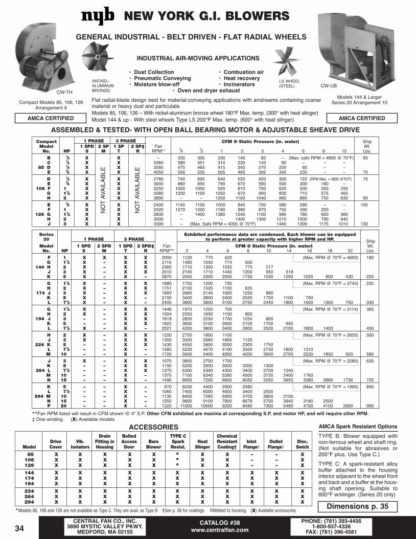
INDUSTRIAL AIR-MOVING APPLICATIONS
• Dust Collection • Combustion air• Pneumatic Conveying • Heat recovery• Moisture blow-off • Incinerators
• Oven and dryer exhaustFlat radial-blade design best for material-conveying applications with airstreams containing coarsematerial or heavy dust and particulate.Models 85, 106, 126 – With nickel-aluminum bronze wheel 180°F Max. temp. (300° with heat slinger)Model 144 & up - With steel wheels Type LS 200°F Max. temp. (600° with heat slinger)
CATALOG #38www.centralfan.com
CENTRAL FAN CO., INC.3890 MYSTIC VALLEY PKWY.
MEDFORD, MA 02155PHONE: (781) 393-4456
1-800-937-4326FAX: (781) 396-458134
AMCA CERTIFIED AMCA CERTIFIED
NEW YORK G.I. BLOWERS
ACCESSORIESDrain Bolted TYPE C Chemical
Drive Vib. Fitting in Access Bare Spark Heat Resistant Inlet Outlet Disc.Model Cover Isolators Housing Door Blower Resist. Slinger Coating† Flange◊ Flange◊ Swich
85 X X X X X * X X – – X106 X X X X X * X X – – X126 X X X X X * X X – – X
144 X X X X X X X X X X X174 X X X X X X X X X X X194 X X X X X X X X X X X
224 X X X X X X X X X X X264 X X X X X X X X X X X294 X X X X X X X X X X X
*Models 85, 106 and 126 are not available as Type C. They are avail. as Type B †See p. 38 for coatings. ◊Welded to housing (X) Available accessories
AMCA Spark Resistant OptionsTYPE B: Blower equipped withnon-ferrous wheel and shaft ring.(Not suitable for abrasives or200°F plus. Use Type C.)
TYPE C: A spark-resistant alloybuffer attached to the housinginterior adjacent to the wheel frontand back and a buffer at the hous-ing shaft opening. Suitable to600°F w/slinger. (Series 20 only)
Compact Models 85, 106, 126Arrangement 9
(NICKEL-ALUMINUMBRONZE)
Models 144 & LargerSeries 20 Arrangement 10
LS WHEEL(STEEL)
Series Exhibited performance data are condensed. Each blower can be equipped20 1 PHASE 3 PHASE to perform at greater capacity with higher RPM and HP. Ship
Model 1 SPD 2 SPD 1 SPD 2 SPD‡ Fan CFM @ Static Pressure (in. water) Wt.No. HP S M T R RPM** 2 4 6 8 10 14 16 18 22 Lbs.
F 1 X X X X 2000 1120 770 420 (Max. RPM @ 70°F = 4600) 180G 11⁄2 X – X X 2110 1460 1050 774 500
144 H 2 X – X X 2360 1710 1300 1035 775 517J 3 X – X X 2510 2100 1710 1440 1200 950 518K 5 X – X – 2870 2500 2300 2050 1720 1530 1200 1020 800 430 225
G 11⁄2 X – X X 1680 1750 1200 720 (Max. RPM @ 70°F = 3745) 235H 2 X – X X 1751 2150 1520 1100 635
174 J 3 X – X X 1900 2660 2140 1600 1250 880K 5 X – X – 2150 3400 2850 2400 2050 1750 1100 760L 71⁄2 X – X – 2400 3800 3600 3100 2750 2440 1800 1600 1300 750 330
G 11⁄2 X – X X 1446 1975 1250 700 (Max. RPM @ 70°F = 3114) 365
194H 2 X – X X 1504 2350 1650 1100 600J 3 – – X X 1618 2850 2250 1700 1250 800K 5 – – X X 1822 3600 3100 2600 2100 1700 950L 71⁄2 X – X – 2021 4200 3800 3400 2900 2500 2100 1800 1400 450
H 2 X – X X 1220 2750 1800 1100 (Max. RPM @ 70°F = 2635) 500J 3 X – X X 1300 3500 2680 1800 1120
224 K 5 – – X X 1430 4550 3800 3000 2300 1750L 71⁄2 – – X – 1585 5220 4670 4100 3350 2750 1800 1310M 10 – – X – 1720 5600 5400 4950 4200 3600 2700 2230 1850 920 580
J 3 X – X X 1070 3850 2700 1700 (Max. RPM @ 70°F = 2280) 635K 5 – – X X 1150 5200 3950 3000 2200 1300
264 L 71⁄2 – – X X 1270 6300 5300 4300 3400 2700 1240M 10 – – X – 1375 7100 6340 5280 4500 3720 2400 1760N 15 – – X – 1490 8000 7200 6800 6050 5250 3950 3380 2860 1736 720
K 5 – – X – 970 6030 4400 2900 2080 (Max. RPM @ 70°F = 1995) 890L 71⁄2 – – X – 1060 7400 6000 4600 3400 2500
294 M 10 – – X – 1130 8400 7260 5900 4700 3800 2100N 15 – – X – 1250 9800 9100 7800 6678 5700 3940 3180 2500P 20 – – X – 1320 11000 10000 9200 8480 7300 5460 4700 4100 2600 990
**Fan RPM listed will result in CFM shown @ 4" S.P. Other CFM exhibited are maxima at corresponding S.P. and motor HP, and will require other RPM.‡ One winding (X) Available models
ASSEMBLED & TESTED- WITH OPEN BALL BEARING MOTOR & ADJUSTABLE SHEAVE DRIVECompact 1 PHASE 3 PHASE CFM @ Static Pressure (in. water) ShipModel 1 SPD 2 SP 1 SP 2 SP‡ Fan Wt.No. HP S M T R RPM** 1⁄4 1⁄2 1 2 3 4 6 8 10 Lbs.
B 1⁄4 X X – 330 300 230 145 60 –n (Max. safe RPM = 4800 @ 70°F) 60C 1⁄3 X X 3360 380 351 310 230 145 60 –n –n –n
85 D 1⁄2 X X 3585 470 465 415 345 270 220 60 –n –nE 3⁄4 X X 4050 556 530 505 465 392 345 235 –n –n 70
D 1⁄2 X X 2780 740 695 640 520 420 300 122 (RPM Max. = 4600 @70°F) 75E 3⁄4 X X 3000 880 850 790 670 560 500 300 180 –n
106 F 1 X X 3250 1000 1000 920 810 700 620 500 350 250G 11⁄2 X X 3580 1200 1100 1050 970 900 830 710 575 465H 2 X X 3890 –n –n 1200 1100 1040 960 860 750 630 90
E 3⁄4 X X 2400 1140 1100 1000 840 700 580 280 –n –n 100F 1 X X 2520 1270 1250 1160 990 870 750 490 200 –n
126 G 11⁄2 X X 2830 –n 1400 1380 1240 1100 990 780 600 360H 2 X X 3000 –n –n –n 1400 1300 1210 1000 790 640J 3 X X 3300 –n (Max. Safe RPM = 4000 @ 70°F) 1440 1300 1175 1010 130
GENERAL INDUSTRIAL - BELT DRIVEN - FLAT RADIAL WHEELS
CW-UBCW-TH
NO
T AV
AIL
AB
LE
NO
T AV
AIL
AB
LE
Dimensions p. 35
Central Fan Catalog_2013_Central Fan Catalog 1/28/13 1:26 PM Page 34

CATALOG #38www.centralfan.com
CENTRAL FAN CO., INC.3890 MYSTIC VALLEY PKWY.
MEDFORD, MA 02155PHONE: (781) 393-4456
1-800-937-4326FAX: (781) 396-4581 35
NEW YORKGEN. INDUSTRIAL
BLOWERARR. 10
LS WHEEL(STEEL)
DIMENSIONS (Inches)OUTLET INLET OUTLET
Size A B C D E F G H j K L M N O
144 151⁄2 101⁄2 111⁄8 81⁄4 93⁄8 12 101⁄4 30 15⁄8 21⁄2 9 77⁄8 20 197⁄8174 171⁄2 125⁄8 131⁄8 101⁄8 111⁄8 141⁄2 121⁄4 341⁄8 15⁄8 3 11 91⁄2 22 217⁄8194 211⁄4 14 16 101⁄4 117⁄8 18 137⁄8 363⁄8 31⁄8 31⁄2 11 93⁄4 22 337⁄8224 251⁄2 161⁄2 187⁄8 13 14 211⁄4 163⁄8 413⁄8 31⁄8 4 13 103⁄4 26 387⁄8264 28 181⁄2 213⁄4 15 161⁄8 241⁄2 187⁄8 441⁄2 41⁄8 41⁄2 15 123⁄8 26 411⁄2294 321⁄2 21 245⁄8 167⁄8 181⁄4 273⁄4 213⁄8 48 41⁄8 51⁄2 17 14 267⁄8 44334 391⁄2 23 273⁄8 183⁄4 203⁄8 307⁄8 237⁄8 531⁄8 41⁄8 6 19 155⁄8 297⁄8 485⁄8364 391⁄2 251⁄2 301⁄4 203⁄4 221⁄2 341⁄8 263⁄8 56 51⁄4 6 21 171⁄4 30 503⁄8
Shaft BaseSize Q R S T V W a b c d diameter Keyway holes
144 – 57⁄8 163⁄8 73⁄8 61⁄2 8 103⁄4 16 111⁄2 93⁄4 17⁄163⁄8 x 3⁄16
9⁄16
174 – 65⁄8 183⁄8 87⁄8 8 91⁄2 131⁄8 191⁄4 133⁄4 111⁄2 17⁄163⁄8 x 3⁄16
9⁄16
194 6 71⁄4 173⁄8 93⁄8 81⁄4 101⁄4 15 225⁄8 17 13 111⁄163⁄8 x 3⁄16
9⁄16
224 61⁄2 81⁄4 203⁄8 107⁄8 93⁄4 113⁄4 175⁄8 265⁄8 20 151⁄4 115⁄161⁄2 x 1⁄4 9⁄16
264 77⁄8 93⁄8 197⁄8 121⁄4 11 13 201⁄4 303⁄8 23 171⁄2 115⁄161⁄2 x 1⁄4 3⁄4
294 85⁄8 101⁄8 203⁄4 135⁄8 113⁄4 143⁄4 23 343⁄8 261⁄8 197⁄8 115⁄161⁄2 x 1⁄4 3⁄4
334 93⁄8 11 233⁄4 16 14 17 253⁄4 381⁄8 291⁄4 223⁄8 23⁄161⁄2 x 1⁄4 3⁄4
364 101⁄4 117⁄8 233⁄4 16 14 17 281⁄2 421⁄8 321⁄4 245⁄8 23⁄161⁄2 x 1⁄4 3⁄4
ShaftModel A B C D* E F G H L* M* N R S T U a** b** c** d** Dia.
85 101⁄2 6 63⁄8 45⁄8 53⁄8 67⁄8 57⁄8 17 5 35⁄8 101⁄4 33⁄8 6 61⁄4 63⁄4 61⁄4 91⁄8 65⁄8 55⁄8 1106 101⁄2 71⁄2 77⁄8 55⁄8 65⁄8 81⁄2 71⁄4 19 6 55⁄8 101⁄4 43⁄8 6 61⁄4 63⁄4 73⁄4 111⁄4 8 63⁄4 1126 121⁄2 81⁄2 10 7 71⁄2 111⁄4 83⁄4 221⁄8 8 55⁄8 125⁄8 4 101⁄2 81⁄8 85⁄8 93⁄8 137⁄8 105⁄8 81⁄8 1
Dimensions should not be used for construction unless certified. **Angular discharge dimensions. See figure above. *D,. L and M are outside dimensions.
NEW YORK COMPACT G.I. BLOWER NICKEL—ALUMINUM—BRONzE RADIAL WHEELARRANGEMENT 9
L, M, & D ARE OUTSIDE DIMENSIONS
OUTLET INLET OUTLET
DIMENSIONS (Inches)
Central Fan Catalog_2013_Central Fan Catalog 1/28/13 1:26 PM Page 35

CATALOG #38www.centralfan.com
CENTRAL FAN CO., INC.3890 MYSTIC VALLEY PKWY.
MEDFORD, MA 02155PHONE: (781) 393-4456
1-800-937-4326FAX: (781) 396-458136
STANDARD MOTORS ARE ODP.SINGLE PHASE THREE PHASE @ 1⁄2" S.P. CFM Approx.
Model 1 Speed 2 Speed 1 Speed 2 Speed Blower O.V. Static Pressure - inches of water (10" S.P. Max.) ShipNo. HP S M T R RPM FPM 1⁄2 1 11⁄2 2 3 4 5 6 Wt.
C 1⁄3 X X X – 1846 1600 1360 1020 765 3800RPM Max @ 70°F 150D 1⁄2 X X X X 2197 1700 1700 1400 1125 850E 3⁄4 X X X X 2560 2400 2040 1800 1530 1275 850
GFE12 F 1 X – X – 2925 2800 2300 2100 1825 1600 1200 800G 11⁄2 X – X – 3315 3200 2720 2500 2300 2100 1700 1350 950H 2 X – X – 3506 3400 2890 2800 2650 2450 2150 1750 1400 1100J 3 X – X – 3506 – 0 2890 2720 2550 2210 2040 1700 220
D 1⁄2 X X X X 1550 1400 1750 1400 1050 645 3315 RPM Max. @ 70°F 200E 3⁄4 X X X X 1820 1700 2150 1806 1525 1200F 1 X X X X 2090 2000 2450 2125 1875 1550 950
GFE15 G 11⁄2 X – X X 2285 2200 2850 2600 2400 2100 1600 1100H 2 X – X – 2500 2400 3200 2900 2800 2500 2050 1600 1100 600J 3 X – X – 2950 3000 3750 3550 3300 3100 2700 2400 1950 1550K 5 X – X – 3195 3200 4128 3870 3612 3354 3096 2838 2322 260
E 3⁄4 X X X X 1220 1600 3150 2500 1950 2900 RPM Max. @ 70°F 290F 1 X X X X 1350 1900 3600 3000 2500 1920G 11⁄2 X – X X 1575 2300 4300 3800 3300 2880 1900
GFE18 H 2 X – X X 1715 2500 4800 4400 4000 3500 2650 1800J 3 X – X X 1975 2900 5600 5100 4800 4400 3750 3000 2300K 5 X – X X 2385 3600 6900 6500 6200 5850 5150 4600 4000 3400L 71⁄2 X – X – 2638 4000 7680 7300 7000 6450 5900 5400 4650M 10 – – X – 2638 – 0 7680 7296 6912 6528 6144 350
Optional set of vibration isolators available. (X) Available models
GENERAL-PURPOSEFUME EXHAUSTERS
Corrosion-Resistant resin construction for use in severe chemical environments• Fiberglass reinforced plastic construction• For severe corrosive fumes and aerosols• Efficient backwardly inclined wheel• Blower discharge rotatable• Standard CW wheel rotation is stock unit• Flanged outlet-slip inlet• 250°F max. operating temperature• WEATHER/DRIVE COVER STD.
Size A• B• C* D E F G H j K L M N Q
12 91⁄8 133⁄4 13 341⁄8 81⁄2 25 151⁄2 141⁄4 93⁄4 12 121⁄4 131⁄8 321⁄2 53⁄415 111⁄8 167⁄8 16 385⁄8 91⁄2 28 171⁄2 171⁄8 12 145⁄8 145⁄8 161⁄8 361⁄2 63⁄418 135⁄8 203⁄4 191⁄2 413⁄4 103⁄4 293⁄8 211⁄4 203⁄8 135⁄8 16 173⁄8 191⁄2 383⁄4 81⁄4
Bare Maximum
Shaft Base fan motor frame
Size R S T V W a b c d Dia. holes weight Open TE
12 67⁄8 163⁄8 73⁄8 61⁄2 8 131⁄2 181⁄8 12 165⁄8 13⁄165⁄8 135 184T 184T
15 87⁄8 173⁄8 87⁄8 8 91⁄2 151⁄2 211⁄4 14 193⁄4 17⁄165⁄8 170 215T 215T
18 93⁄4 173⁄8 93⁄8 81⁄4 101⁄4 18 251⁄8 165⁄8 233⁄4 111⁄165⁄8 240 215T 215T
O.D. of inlet collar. Slip inlet only Tolerance ±1⁄8" •Inside dimensions *Outside dimensions
NOTE: Sizes 24, 30 & 36 are also available with severalweek lead time. (See page 37 for other plastic blowers.)CW-UB (stock unit)
CCW Rotation(special orderfor CCW units)
( )SLIP INLET
Central Fan Catalog_2013_Central Fan Catalog 1/28/13 1:26 PM Page 36

CATALOG #38www.centralfan.com
CENTRAL FAN CO., INC.3890 MYSTIC VALLEY PKWY.
MEDFORD, MA 02155PHONE: (781) 393-4456
1-800-937-4326FAX: (781) 396-4581 37
BELT DRIVE WITH TEFC MOTOR*CFM Approx.
Blwr. 1 3 Static Pressure (inches water) ShipModel Wheel RPM Phase Phase Wt.No. HP Dia. @ 1" S T 1 2 3 4 5 6 7 Lbs.
C 1⁄3 101⁄2 1829 X X 500 400 300 200D 1⁄2 2157 X X 650 550 450 350 250
PVC10 E 3⁄4 O.V = 2390 X X 750 700 600 500 450 350 175F 1 CFM 2632 X X 850 800 700 650 550 500G 11⁄2 0.196 3013 X X 1000 950 850 800 750 650
E 3⁄4 14 1510 X X 1050 900 700 500F 1 1660 X X 1200 1050 900 700 550 400
PVC14 G 11⁄2 O.V. = 1910 X X 1450 1300 1150 1000 850 700 550 220H 2 CFM 2068 X X 1600 1450 1350 1200 1050 950 800J 3 0.349 2393 – X 1900 1750 1650 1550 1400 1300 1000
F 1 171⁄2 1175 X X 1550 1250 900 600G 11⁄2 1225 X X 1850 1600 1350 1050 800
PVC17 H 2 O.V. = 1442 X X 2100 1850 1600 1350 1100 900 650 260J 3 CFM 1625 – X 2450 2250 2050 1850 1650 1400 1200K 5 0.545 1709 – X 2600 2600 2600 2500 2300 2100 1900
(X) Available models Vibration isolators available
SEE PP. 36, 38 FOR FRP BELT DRIVEN BLOWERS AND ABRIEF LISTING OF SOME CORROSIVE VAPORS AND
PROTECTIVE COATINGS FOR METALS.
Lab blowers for corrosion resistance where metal blowers with or without protective coatings prove unsatisfactory. Standard motors are ODP and not exposed to ducted fumes through blower. Max. temp. - 140°F.Model AA - Polypropylene wheel and PVC housing CCW-UB or CCW-THModel A - Polypropylene wheel and FRP housing CCW rotation - any disch.NOTE: When strong oxidizing acids (nitric, sulfuric, chronic) are present use Model A with PVC wheel
PVC wheel is not suitable when vapor phase solvents are present, however.
DIMENSIONS
Model10 14 17
A 101⁄2 141⁄4 171⁄4B 91⁄16 12 1415⁄16
C 815⁄16 1015⁄16 135⁄8D O.D. 6 8 10E 4 5 6F 11 14 17G 14 16 17J 17 18 19K O.D. 6 8 10L 75⁄8 99⁄16 111⁄8M 123⁄4 143⁄4 153⁄4N 133⁄4 16 191⁄2P 15 171⁄4 203⁄4R Max. 181⁄2 231⁄2 26S Max. 141⁄2 165⁄16 183⁄4T 93⁄4 121⁄2 151⁄2V 13⁄16 13⁄16 17⁄16
• 100% corrosion Resistant to most inorganic chemicals*• Non-flammable…Self extinguishing• Operation to 150°F• Electrical Insulator• Drain• Steel Reinforced Wheel• Belt and shaft guard standard
See page 38 for summaryof chemical activity*NOTE: SPECIFY CHEMICAL SUBSTANCE& OPERATING TEMP.
Clockwise RotationUpblast DischargeARR. #9
*1Phase 3 Phase Motor CFM @ S.P. Shp.1 SPD 2 SPD
Model HP RPM S M T Cover 0 1⁄4 1⁄2 1 11⁄2 Wt. Lbs.
AA 1⁄6 1725 X X X X 250 225 180 30A 1⁄3 1725 X X X X 1100 1025 995 800 500 50
(X) Available models *1Ø X.P. models available.
DimensionsModel A, in. B, in. C, in. D, in. E, in. F, in. G, in. j, in. K, in.
AA 55⁄8 65⁄8 33⁄4 51⁄2 9 7 131⁄2 11 41⁄2A 91⁄2 71⁄4 41⁄2 8 101⁄2 71⁄4 171⁄4 151⁄8 8
Lab BlowersDIRECT DRIVE
Belt Drive Industrial PVC Blowers Corrosion Resistant Radial Blade Blower
SOLID POLYVINYL CHLORIDE HOUSINGAMCA CERTIFIED
CCW-UBModel AA, A
DO NOT EXPOSE THESE BLOWERS TOPERCHLORIC ACID.
See p. 36 for FRP blowers
OUTLETINLET
Central Fan Catalog_2013_Central Fan Catalog 1/28/13 1:26 PM Page 37

CATALOG #38www.centralfan.com
CENTRAL FAN CO., INC.3890 MYSTIC VALLEY PKWY.
MEDFORD, MA 02155PHONE: (781) 393-4456
1-800-937-4326FAX: (781) 396-458138
CHEMICAL RESISTANCE OF POLYVINYL CHLORIDE (PVC) & VINYL ESTER (FRP)
PVC provides FAIR-EXCELLENT protection to base metals exposedto the following chemicals at room temperature:
Acetic acid (dilute) Aqua regia • Ethylene glycol • Mineral oil • Sodium nitrateAlcohol-methyl ethyl Barium carbonate Ferric chloride Naptha • Sodium sulphateAluminum chloride • Beer Ferric nitrate Nitric acid (dilute) • Stannous chloride
o Aluminum flouride Benzoic acid Ferric sulphate • Nitrous oxide • Sulphuric acid (dilute)Aluminum hydroxide Calcium carbonate o Flourine • Oxygen • Tannic acid
• Aluminum nitrate Calcium chloride o Formaldehyde • Perchloric acid (dilute) Trisodium phos.Aluminum sulphate Calcium nitrate o Hydrochloric acid Phosphoric acid • UreaAlum Calcium sulphate Hydrogen peroxide Photo solutions Water-salt
• Ammonia gas (Dry) Caustic • Hydrogen sulphide Plating solutions • Zinc chlorideAmmonium chloride Chlorine • Kerosene Propane • Zinc sulphate
• Ammonium carbonate • Chromic acid • Lead acetate o Potassium hydroxideo• Ammonium hydroxide • Citric acid Magnesium carbonate Soda ash• Ammonium nitrate Copper sulphate Magnesium chloride Sodium chloride
Ammonium sulphate Crude oil • Magnesium sulphate Sodium cyanide• Ethyl alcohol Sodium hydroxide
• Does not actively corrode bare aluminum o Will attack glass in FRP or Vinyl Ester
PVC is ATTACKED to the degree that it does NOT provide adequate protectionagainst the following chemicals at room temperature:
†• Acetone • Asphalt o• Ethers † Ketones * Sodium acetate* Alcohol-Amyl, Benzyl • Benzene Ethly acetate Methyl-Ethyl ketone * Sodium phosphate
o* Ammonia (liquid) * Bromine o Ethylene oxide Methylene chloride *• Stearic acid* Ammonium flouride * Butane * Formic acid *• Naphthalene Sulphate liquors* Ammonium phosphate *• Butyl acetate *• Gasoline Nitric acid (anhyd.) * Sulphur dioxide (wet)
*• Amyl acetate * Carbon tet. * Heptane o*• Phenol *• Toluene* Amyl chloride * Chloroform * Hexane Phosgene o*• Trichlorethylene
o* Aniline Creosote * Hydrogen phosphide * Propyl alcohol *• TurpentineEsters o* Hydroflouric acid *• Sodium bisulphate Vinyl acetate
* Iodine *• Sodium nitrite *• Xylene* Sodium peroxide
• Does not actively corrode bare aluminum †Use 316 stainless * Use PVDF o Will attack glass in FRP or Vinyl Ester
Coatings Summary: (Central Fan will apply the following coatings.)PVC-Sprayed, air dryed, multilayer coatings have good-to-excellent resistance to most acids, alkalies and marine exposures. Coatings are flexible,
fairly durable, and good to 150°F. The most commonly used protective coating. Unsuitable in most vapor phase organic solvents.Eisenheiss-Synthetic polyester resin which is sprayed, air dryed in multilayer coatings providing tough impermeable coatings good to 150°F.
Chemical resistance similar to PVC except notably a slightly better performance when exposed to tricholorethylene, benzene, carbon tet., or gaso-line. Does not perform well in hydrogen peroxide.
Heresite-A sprayed phenolic resin coating which provides good resistance to most common solvents, organic and inorganic acids. Not recommended for caustics, alkalies, and oxidizing agents. Good to 120°F. Affords fair resistance to methyl ethyl ketone, methylene chloride,trichlorethylene.
Epoxy-One of the most durable all-purpose coatings which withstands reasonable abrasion and most chemicals.Baked epoxy-(Factory applied by Peerless on all blowers) effectively protects carbon steel surfaces from normal atmospheric conditions. Is attacked
by acids, alkalies, and certain solvents. Can provide effective undercoating. CENTRAL FAN DOES NOT APPLY BAKED EPOXY COATINGS.
BLOWERS: Rigid PVC has good all-around corrosion resistance and is usually the economic material of choice. However, PVC becomes brittle at sub-zero tem-peratures and loses its strength above 150°F. Thus, steel reinforcement is used in PVC blower wheels. Do not use FRP above 250°F, or PVDF above 180°F.All are spark resistant (electric insulator). Graphite impregnation into FRP can make it conductive to control static electricity. UV radiation (direct sun) willdestroy polypropylene. Although slightly more in initial cost, FRP blowers prove to be more economical where the environment is severe and maximum dura-bility is desired. Polyvinylidene (PVDF) will withstand inorganic acids and bases, organic acids, alcohols, aliphatic and aromatic hydrocarbons and halo-genated solvents and halogens (except fluorine).
NOTE: BECAUSE OF THE INHERENT FRAGILITY OF ALL COATINGS, NO EXPLICIT WARRANTY OF SERVICEABILITY CAN BE MADE.
Caution: Use these data as a guide only at 70°F.Consult the chemical mfr. for complete data.
Central Fan Catalog_2013_Central Fan Catalog 1/28/13 1:26 PM Page 38

CATALOG #38www.centralfan.com
CENTRAL FAN CO., INC.3890 MYSTIC VALLEY PKWY.
MEDFORD, MA 02155PHONE: (781) 393-4456
1-800-937-4326FAX: (781) 396-4581 39
Isolators for Vibration and Noise ControlThe most effective vibration and noise control is obtained when the isolator deflects up to its maximum limit…without exceeding that maximum deflection. For proper selection:
1. Equipment weight - greater deflection (up to max.) provides maximum isolation
2. Equipment RPM - lower than 1200RPM use springs for maximum isolation (Higher RPM’s use rubber regardless of substructure)
3. Equipment Location-(a)Rigid sub-structure-use rubber or springs(b)Flexible sub-structure-use springs (such as on upper levels of building)
Model Cap Max. Defl. Spring Dimensions (in.)Fig. Isolator Color lbs. In. O.D. A B C D E F G
RD 35 Blue 35 .40 .– 1.75 3.13 .85 5⁄16 1.25 2.37 .34RD 70 Red 70 .40 .– 1.75 3.13 .85 5⁄16 1.25 2.37 .34A RD 135 Blue 135 .50 .– 2.37 3.87 1.25 3⁄8 1.75 3.00 .34RD 240 Red 240 .50 .– 2.37 3.87 1.25 3⁄8 1.75 3.00 .34RD 375 Black 375 .50 .– 2.37 3.87 1.25 3⁄8 1.75 3.00 .34
FDS-35 Blue 35 1.52 1.75 2.63 2.63 3.50 .62 3.88 3⁄8 .–FDS-70 Green 70 1.36 1.75 2.63 2.63 3.50 .62 3.88 3⁄8 .–B FDS-120 Gray 120 1.18 1.75 2.63 2.63 3.50 .62 3.88 3⁄8 .–FDS-220 Brown 220 1.10 1.75 2.63 2.63 3.50 .62 3.88 3⁄8 .–FDS-370 Orange 370 1.00 1.75 2.63 2.63 3.50 .62 3.88 3⁄8 .–
FRS-35 Blue 35 1.52 1.75 3.0 4.75 5.0 .50 5.0 3.75 .44FRS-70 Green 70 1.36 1.75 3.0 4.75 5.0 .50 5.0 3.75 .44C FRS-120 Gray 120 1.18 1.75 3.0 4.75 5.0 .50 5.0 3.75 .44FRS-220 Brown 220 1.10 1.75 3.0 4.75 5.0 .50 5.0 3.75 .44FRS-375 Orange 370 1.00 1.75 3.0 4.75 5.0 .50 5.0 3.75 .44
SL-35 Blue 35 1.52 1.75 2.12 6.12 3.50 3⁄8 4.00 5.63 .31SL-70 Green 70 1.36 1.75 2.12 6.12 3.50 3⁄8 4.00 5.63 .31D SL-120 Gray 120 1.18 1.75 2.12 6.12 3.50 3⁄8 4.00 5.63 .31SL-220 Brown 220 1.10 1.75 2.12 6.12 3.50 3⁄8 4.00 5.63 .31SL-370 Orange 370 1.00 1.75 2.12 6.12 3.50 3⁄8 4.00 5.63 .31
RHD-35 Blue 35 .40 .– 2.25 2.0 3.0 .421 1.37 .375 .–E RHD-75 Red 75 .40 .– 2.25 2.0 3.0 .421 1.37 .375 .–RHD-120 Green 120 .40 .– 2.25 2.0 3.0 .421 1.37 .375 .–RHD-170 Black 170 .50 .– 3.00 2.25 4.5 .656 1.87 .625 .–
SH-35 Blue 35 1.52 1.75 3.69 2.25 5.25 .88 3.00 .– .–SH-70 Green 70 1.36 1.75 3.69 2.25 5.25 .88 3.00 .– .–F SH-120 Gray 120 1.18 1.75 3.69 2.25 5.25 .88 3.00 .– .–SH-220 Brown 220 1.10 1.75 3.69 2.25 5.25 .88 3.00 .– .–SH-370 Orange 370 1.00 1.75 3.69 2.25 5.25 .88 3.00 .– .–
SRH-35 Blue 35 1.55 1.75 3.69 2.25 7.38 .75 3.00 1.48 .–SRH-70 Green 70 1.42 1.75 3.69 2.25 7.38 .75 3.00 1.48 .–G SRH-120 Gray 120 1.29 1.75 3.69 2.25 7.38 .75 3.00 1.48 .–SRH-220 Brown 220 1.30 1.75 3.69 2.25 7.38 .75 3.00 1.48 .–SRH-370 Orange 370 1.33 1.75 3.69 2.25 7.38 .75 3.00 1.48 .–
ARS-30 (For VAV) 30 .50 .– 4.75 2.19 .50 .27 .– .– .–H ARS-70 Boxes 70 .50 .– 4.75 2.19 .50 .27 .– .– .–
Central Fan Catalog_2013_Central Fan Catalog 1/28/13 1:26 PM Page 39

CATALOG #38www.centralfan.com
CENTRAL FAN CO., INC.3890 MYSTIC VALLEY PKWY.
MEDFORD, MA 02155PHONE: (781) 393-4456
1-800-937-4326FAX: (781) 396-458140
Centrifugal Roof ExhaustersDirect Driven
• All aluminum construction - com-pact design
• A non-overloading, aluminum wheel• Quiet, vibration free motor mount-
ings• Motor outside exhaust air stream,
auto thermal, ODP• Bird screen
• Galvanized steel frame for strength• Factory wired with polarized discon-
nect plug (except explosion resist-ant motors)
• Electronically commutated motormodels available (Special order)
• Hurricane rated models available(Special order)
DIMENSIONSShutter Curb
Model A* B C E O.D. O.D. I.D.PRN 80 131⁄2 9 183⁄4 9 121⁄2 91⁄4PRN 100, 110 16 131⁄4 211⁄8 37⁄8 12 151⁄4 12PRN 126, 145 21 163⁄8 273⁄4 47⁄8 16 20 163⁄4
*Outside dimension
Curb Dimensions
Model ShipNo. O.D. I.D. M Wt.
C1312 121⁄2 91⁄4 8 18C1512 151⁄4 12 10 21
C1912 181⁄2 151⁄4 131⁄2 26C2012 20 163⁄4 143⁄4 31
C2412 231⁄2 201⁄4 181⁄4 34C2812 271⁄2 241⁄4 221⁄4 39
C3212 311⁄2 281⁄4 261⁄4 43C3412 331⁄2 301⁄4 281⁄4 46
C3612 351⁄2 321⁄4 301⁄4 48C3812 371⁄2 341⁄4 * 50
C4012 391⁄2 361⁄4 341⁄4 52C4312 43 393⁄4 373⁄4 56
C4612 451⁄2 421⁄4 401⁄4 65C4912 49 453⁄4 * 69
C5512 55 513⁄4 * 75C6112 61 573⁄4 * 80
* No shelf
CURB ADAPTERS**Model Dimensions
No. A B
CA 1815 18 151⁄2CA 1855 181⁄2 151⁄2CA 1915 19 151⁄2CA 2015 201⁄2 151⁄2CA 2118 21 181⁄2CA 2218 22 181⁄2CA 2220 22 201⁄2CA 2515 25 151⁄2CA 2518 25 181⁄2CA 2520 25 201⁄2CA 2820 28 201⁄2CA 2823 28 231⁄2
ROOF FAN CURBS AND ADAPTERS• 18 gauge galv. steel• fiberglass insulation• neoprene pad• continuous welds• sturdy shutter shelf• self flashingStandard height = 12"(other heights available)
Pitched curbs are special order.
CURB ADAPTERS• Sturdy…weather tight.• Continuous welds.• 18 ga. galv. steelAdapter permits equal (based on performance) fanreplacement without disturbing existing roof curb.**Many other sizes not shown are in stock.
1750 RPM CFM Ship120v 1 Phase 3 Phase 120v 1Ø 12" Static Press. (in. water) Wt.
Roof 1 Speed Var. Sp. 1 Speed XP Motor Drop-in Ht. Sones lbs.Model HP S M T SX† Shutter Curb RPM @ 1⁄4 0 1⁄8 1⁄4 3⁄8 1⁄2 3⁄4 1 (Fan)
PRN80 1⁄10 X X(v) – – B9. C1312.
*1550 7.8 580 496 428 352 254 243.2 Amps
PRN100 1⁄10 X X(v) – 1⁄6 HP B12 C1512
. *1550 5.8 770 690 610 520 3801300 4.0 650 550 450 280
273.2 Amps 1050 3.0 520 410 210850 430 270
PRN110 1⁄10 X X(v) – 1⁄6 HP B12 C1512. *1550 11.3 1090 990 890 780 650 210
1300 7.6 910 790 670 510 270273.2 Amps 1050 4.7 740 590 400
860 600 420
PRN126 1⁄4 X X(v) – 1⁄4 HP B16 C2012. *1625 12.0 1760 1670 1560 1450 1320 1040 680
432.6 Amps
1300 9.0 1410 1290 1150 980 800 2701050 6.6 1140 980 790 540 150
PRN1451⁄2 X X(v) – 1⁄2 HP B16 C2012
. *1625 14.5 2540 2420 2300 2180 2060 1780 1440461300 10.7 2030 1880 1730 1580 1400 9205.5 Amps
1050 7.6 1640 1460 1270 1030 710
*Maximum RPM shown obtained with the standard one speed motor. For all other RPMs add solid state speed controller(v) Variable speed w/control. Chemical resistant coating available (X) Available models† Because of 1725 RPM XP motor, the CFM shown will be increased proportionately. Expl. Proof motors are single speed only. Disc. sw. extra (Not installed) See p. 10
Central Fan Catalog_2013_Central Fan Catalog 1/28/13 1:26 PM Page 40

CATALOG #38www.centralfan.com
CENTRAL FAN CO., INC.3890 MYSTIC VALLEY PKWY.
MEDFORD, MA 02155PHONE: (781) 393-4456
1-800-937-4326FAX: (781) 396-4581 41
DIMENSIONS 12" CURB SHUTTER
Model A* B C D OD ID OD
PV 75 21 231⁄2 233⁄4 2 20 163⁄4 16PV 100 21 231⁄2 233⁄4 2 20 163⁄4 16
PV 120 21 263⁄4 291⁄2 2 20 163⁄4 16PV 135 21 263⁄4 291⁄2 2 20 163⁄4 16
PV 150 24 31 35 2 231⁄2 201⁄4 20PV 165 24 31 35 2 231⁄2 201⁄4 20
PV 180 28 351⁄2 391⁄2 2 271⁄2 241⁄4 24PV 200 28 351⁄2 391⁄2 2 271⁄2 241⁄4 24
PV 240 34 381⁄2 461⁄2 2 331⁄2 301⁄4 30
PV 300 40 37 53 2 391⁄2 361⁄4 36
PV 365 46 46 64 2 451⁄2 421⁄4 42
*Outside dimension
FEATURES• Non-overloading aluminum impeller• Prelubricated, sealed bearings• Bird screen• Heavy gauge aluminum housings• Larger sizes available (Special order)
• Performance certified to 2" static press.• Motor and drive out of exhaust stream• Welded 18 ga. galv. insulated curb std.
curb ht. = 12" See p. 40 for curb detail.• Hurricane rated models available
(Special order)ALUMINUM IMPELLER BELT DRIVEN
CENTRIFUGAL EXHAUSTERS
SINGLE PHASE 3 PHASE CFM ShipModel 1 Speed 2 Speed 1 Speed 2 Speed 12" Fan Sones Static Pressure (inches H2O) wt.No. HP S M T R Curb Shutter RPM @ 1⁄4" 0 1⁄4 1⁄2 3⁄4 1 11⁄2 2 lbs.
PV75 A 1⁄6 X – – – C2012 B16 1669 8.6 830 730 620 480 140 85B 1⁄4 X X X – 1909 10.7 940 860 770 660 530
A 1⁄6 X – – – 1625 9.1 1200 1100 850 550 300PV100 B 1⁄4 X X X – C2012 B16 1869 12.5 1400 1300 1200 1000 700 85
C 1⁄3 X X X – 1993 14.6 1500 1400 1300 1200 1100 600
A 1⁄6 X – – –C2012 B16
1300 7.8 1440 1270 1050 730PV120 B 1⁄4 X X X – 1580 10.9 1750 1610 1450 1270 1020 90
C 1⁄3 X X X – 1750 13.4 1940 1810 1680 1520 1345 750
B 1⁄4 X X X – 1480 11.7 2000 1800 1600 1200 900 93PV135 C 1⁄3 X X X – C2012 B16 1616 13.6 2200 2000 1800 1600 1300
D 1⁄2 X X X X 1823 17.1 2500 2300 2200 2000 1800 1300 400 97
C 1⁄3 X X X – 1185 11.2 2500 2240 1950 1610 1170 111PV150 D 1⁄2 X X X X C2412 B20 1365 14.1 2870 2650 2400 2130 1830 730
E 3⁄4 X X X X 1555 17.6 3270 3080 2870 2660 2410 1840 119
B 1⁄4 X X X – 975 9.1 2700 2200 1700 1100 112C 1⁄3 X X X – 1074 11.4 3000 2500 2100 1600
PV165 D 1⁄2 X X X X C2412 B20 1244 15.7 3400 3000 2700 2300 1800E 3⁄4 X X X X 1456 19.2 3900 3600 3300 2900 2600 1600F 1 X X X X 1584 21 4200 3900 3700 3400 3200 2400 1600 130
D 1⁄2 X X X X 830 11.7 4340 3800 3080 1930 206
PV180 E 3⁄4 X X X XC2812 B24
940 15.6 4920 4440 3920 3100 2020F 1 X X X X 1050 19.7 5490 5060 4600 4030 3250G 11⁄2 X – X X 1185 22.0 6200 5800 5430 5010 4440 2870 227
D 1⁄2 X X X X 798 10.9 4500 3900 2900 1900 1400 207E 3⁄4 X X X X 904 13.9 5100 4600 3700 3000 2100
PV200 F 1 X X X X C2812 B24 1000 16.7 5700 5200 4600 3800 3200G 11⁄2 X – X X 1133 20 6500 6000 5500 5000 4200 3000H 2 X – X X 1250 23 7100 6700 6300 5800 5200 3800 2100 226
D 1⁄2 X X X X 657 10.4 5900 4800 3400 2200 254E 3⁄4 X X X X 758 13.7 6700 5800 4600 3300 2400
PV240 F 1 X X X X C3412 B30 856 17 7400 6700 5600 4500 3300G 11⁄2 X – X X 977 21 8500 7800 6900 6100 5000 2600H 2 X – X X 1033 23 8800 8300 7800 7200 6500 4600 1000 274
E 3⁄4 X X X X 583 15.5 8800 7400 5900 4000 360F 1 X X X X 646 18 9800 8400 7000 5500 3400
PV300 G 11⁄2 X – X X C4012 B36 749 21 11000 10000 8800 7400 6000H 2 X – X X 814 24 12000 11000 10100 9000 7800 5200J 3 X – X X 834 25 –m 11300 10600 9900 9200 7500 3900 418
F 1 X X X X 443 13 12200 10000 7500 4600 2700 422G 11⁄2 X – X X 515 16.1 14000 12100 10000 8200 5200
PV365 H 2 X – X X C4612 B42 571 18.7 15500 13700 12000 10000 7900J 3 X – X X 658 23 17600 16100 14600 13000 11400 7300K 5 – – X X 731 27 19000 18100 17200 16200 15300 12800 10000 487
(X) Available models Motor controls p.10
Central Fan Catalog_2013_Central Fan Catalog 1/28/13 1:26 PM Page 41

CATALOG #38www.centralfan.com
CENTRAL FAN CO., INC.3890 MYSTIC VALLEY PKWY.
MEDFORD, MA 02155PHONE: (781) 393-4456
1-800-937-4326FAX: (781) 396-458142
Dimensions Curb Shutter Wall Flange
Model A* B C D OD ID OD OD Flange
PDU110 131⁄2 163⁄8 205⁄8 127⁄8 121⁄2 91⁄2 9 13 17
PDU120 19 191⁄2 263⁄8 161⁄2 181⁄2 151⁄4 15 181⁄2 221⁄2PDU135 19 207⁄8 263⁄8 161⁄2 181⁄2 151⁄4 15 181⁄2 221⁄2PDU165 24 237⁄8 301⁄8 22 231⁄2 201⁄4 20 231⁄2 271⁄2PDU185 28 253⁄4 345⁄8 22 271⁄2 241⁄4 24 271⁄2 311⁄2
*Outside dimension
ACCESSORIES:Curb hinge kit Wall mount flangeExternal grease trough Chemical Resistant CoatingAccess panel in fan windband
DIRECT DRIVECentrifugal Upblast Ventilators for Commercial Kitchen Exhaust Systems
MEETS NATIONAL FIREPROTECTION ASSOCIATION
STANDARD NFPA 96
LISTED CLASSIFICATIONYZHWSUBjECT 762®
UL
*NFPA 96 Requires:• Min. curb height 18" (disch. > 40" above roof)• Fan-curb hinge assembly to allow cleaning fan and duct• 500 FPM min. duct velocity• External grease trough• Prohibits duct damper (shutter)• Access panel in fan windband
CFM Fan(See Note) Static Pressure (inches water H2O) ship
1 Speed Var. Spd. Fan Sones wt.Model HP S V Shutter* Curb* RPM @ 1⁄4 0 1⁄8 1⁄4 3⁄8 1⁄2 5⁄8 3⁄4 1 11⁄4 lbs.
PDU08012"H 1600** 9.2 385 368 350 323 253
433.0 amps 1⁄10 X X(V)B9 C1312 1300 7.7 313 292 261
28" H*115vC1328
PDU11012"H 1550** 10.6 1017 951 885 816 731 617 506
433.0 amps 1⁄10 X X(V)B9 C1312 1300 7.6 853 774 693 588 454 270
28" H* 1050 5.5 689 591 468 292115vC1328 860 4.2 564 441 243
PDU12012" H 1680** 13.6 1753 1689 1611 1522 1433 1295 1155
722.6 amps 1⁄4 X X(V)B15 C1912 1550 13.1 1617 1548 1457 1360 1233 1082
24" H* 1300 9.5 1356 1269 1154 1001115vC1924 1160 8.7 1210 1106 972 770
PDU13512" H
1695** 19.1 2736 2654 2572 2491 2410 2328 2243 2052 1782
725.6 ampsB15 C1912
1550 16.9 2502 2412 2323 2234 2145 2053 1953 1683 14011⁄2 X X(V)
24" H*1330 13.0 2098 1991 1886 1779 1665 1522 1347
115vC1924
1050 9.7 1695 1563 1431 1283 1070860 7.6 1388 1228 1053 797
PDU1651⁄2 X X(V)
12" H 1160** 18.1 3242 3087 2934 2781 2621 2439 2194 1692
1026.3/2.9 ampsB20 C2412 1050 16.0 2935 2764 2595 2421 2227 1962 1680
18" H* 860 10.7 2404 2196 1986 1725 1385115/208-230v C2418
PDU1851⁄2 X X(V)
12" H 1160** 17.3 4340 4193 4047 3900 3751 3602 3420
1796.3/2.9 ampsB24 C2812 1050 15.8 3940 3782 3620 3475 3260 3130 2859
18" H* 860 10.9 3269 3138 2889 2773 2424115/208-230v C2818
**Max RPM with std. motor. Use variable speed control for other RPM. (V) Variable speed includes solid state control (X) Available models
ALUMINUMAIRFOIL IMPELLER
NOTE:
WALL MOUNT
DIRECT DRIVE IF NFPA 96 COMPLIANCE REQUIRED SEE NOTE BELOW
• Non-overloading aluminum backwardcurved impeller
• Shaded pole or permanent split cap.motors with built-in thermal overloadprotection and extended life ballbearings
• Safety disconnect switch• Integral grease trough and drain• Heavy gauge aluminum housing with
extra strength galv. steel base
• Optional solid state variable speedcontrol
• 300°F continuous duty and 600°Fflare-up tested
• Bird screen• Electronically commutated motor
models available (Special order)• Hurricane rated models available
(Special order)
Roof and Wall Mounting
Central Fan Catalog_2013_Central Fan Catalog 1/28/13 1:26 PM Page 42

CATALOG #38www.centralfan.com
CENTRAL FAN CO., INC.3890 MYSTIC VALLEY PKWY.
MEDFORD, MA 02155PHONE: (781) 393-4456
1-800-937-4326FAX: (781) 396-4581 43
1 PHASE 3 PHASE CFMModel 1 Speed 2 Speed 1 Speed 2 Speed
Curb
Optional Fan Sones Static Pressure (in. H2O) ShipNo. HP S M T R
12"Shutter RPM @ 1⁄4" 0 1⁄4 1⁄2 3⁄4 1 11⁄2 2 Wt.
B 1⁄4 X X X – C2412
B20
1400 14.5 2012 1774 1527 1282 882 120C 1⁄3 X X X – 1550 16.2 2230 2016 1788 1578 1333
PNU135RG D 1⁄2 X X X X 1780 17.5 2565 2380 2187 1992 1810 1320E 3⁄4 X X X X C2418* 2050 21.0 2950 2790 2630 2455 2290 1960 1500 135
C 1⁄3 X X X –C2812
B24
1120 13.8 2936 2570 2196 1810 180D 1⁄2 X X X X 1287 17.0 3377 3064 2728 2417 2063
PNU165RG E 3⁄4 X X X X 1480 22.0 3881 3608 3323 3034 2766 2066F 1 X X X X 1632 25.0 4400 4100 3750 3390 3050 2600G 11⁄2 X –m X X
C2818*1771 27.0 4708 4487 4277 4071 3866 3300 2700 215
D 1⁄2 X X X XC2812
B24
948 14.0 4414 3746 3285 2664 1724 240E 3⁄4 X X X X 1085 17.2 5052 4406 4064 3574 2994
PNU200RG F 1 X X X X 1194 21.0 5560 4924 4666 4216 3742 2457G 11⁄2 X – X X 1360 26.0 6328 5698 5548 5145 4752 3878 2645H 2 X – X X
C2818*1496 28.0 6966 6332 6263 5897 5532 4807 3918 275
E 3⁄4 X X X XC3412
B30
725 15.3 5890 5188 4448 3588 290F 1 X X X X 797 17.5 6474 5840 5185 4457 3510
PNU245RG G 11⁄2 X – X X 913 21.0 7417 6863 6297 5706 5060 2289H 2 X – X X 1005 24.0 8164 7660 7150 6632 6074 4780J 3 X – X X
C3418*
1150 27.0 9342 8900 8460 8010 7556 6570 5346 340
F 1 X X X XC4012
B36
596 14.5 9541 7975 6373 5078 415G 11⁄2 X – X X 692 17.3 10652 9515 8215 6910 5701
PNU300RG H 2 X – X X 760 21.0 11615 10625 9575 8480 7125Roof J 3 X – X X 879 26.0 13225 12450 11515 10225 9580 8196Only K 5 – – X X
C4018*
987 31.0 14622 14131 13619 13055 12444 11262 9904 530
G 11⁄2 X – X XC4612
B42
490 15.2 13750 11810 9914 7700 510H 2 X – X X 548 17.0 15022 13500 11640 9575 8473
PNU365RG J 3 X – X X 633 23.0 17503 15925 14350 12410 10885Roof K 5 – – X X 757 31.0 20500 19390 18175 16750 15479 12450Only L 71⁄2 – – X X
C4618*
813 35.0 21692 20967 20210 19378 18476 16730 13815 620
(X) Available models
Dimensions Curb Shutter Wall Flange
Model A* B C D OD ID OD OD Flange
PNU135 24 273⁄8 331⁄2 221⁄8 231⁄2 201⁄4 20 231⁄2 271⁄2PNU165 28 26 38 221⁄2 271⁄2 241⁄4 24 271⁄2 311⁄2PNU200 28 311⁄2 393⁄4 283⁄4 271⁄2 241⁄4 24 271⁄2 311⁄2PNU245 34 361⁄4 443⁄4 311⁄2 331⁄2 301⁄4 30 331⁄2 371⁄2PNU300 40 421⁄2 553⁄8 341⁄4 391⁄2 361⁄4 36 – –
PNU365 46 46 66 411⁄4 451⁄2 421⁄4 42 – –
*Outside dimension
ACCESSORIES:Curb hinge kit(PNU245 max. for hinge kit)
External grease troughWall mount flange(PNU245 max. size for wall mtg.)Access panel in fan windband
Roof and Wall Mounting• UL LISTED • NFPA 96 COMPLIANCE • AMCA CERTIFIED AIR & SOUND• • GREASE COLLECTOR & DRAIN • BIRD SCREEN
• ALUMINUM WHEEL & HOUSING • PRELUBRICATED SEALED BEARINGS • EXTERNAL WIRING BOX• HURRICANE RATED MODELS AVAILABLE (SPECIAL ORDER)
BELT DRIVECentrifugal Upblast Ventilators forCommercial Kitchen Exhaust Systems
MEETS NATIONAL FIREPROTECTION ASSOCIATION
STANDARD NFPA 96
LISTED CLASSIFICATIONYZHWSUBjECT 762®
UL
*NFPA 96 Requires:• Min. curb height 18" (disch. > 40" above roof)• Fan-curb hinge assembly to allow cleaning fan and duct• 500 FPM min. duct velocity• External grease trough• Prohibits duct damper (shutter)• Access panel in fan windband
NOTE:
WALL MOUNT
IF NFPA 96 COMPLIANCE REQUIRED SEE NOTE BELOW
18"
BELT DRIVE
Motor Disconnect Switches
Single Phase Three Phase
HP 1 Sp. 2 Sp. 1 Sp. 2 Sp.1⁄6-3⁄4 X X X X1-2 X X X X3 X – X X5 – – X X
71⁄2-10 – – X* –
*460V-550V only (X) Available
Central Fan Catalog_2013_Central Fan Catalog 1/28/13 1:26 PM Page 43

CATALOG #38www.centralfan.com
CENTRAL FAN CO., INC.3890 MYSTIC VALLEY PKWY.
MEDFORD, MA 02155PHONE: (781) 393-4456
1-800-937-4326FAX: (781) 396-458144
KITCHEN EXHAUST FANSNFPA 96 AND UL YzHW #762
PAGES 42,43
1 PHASE 3 PHASE CFMModel 1 Speed 2 Speed 1 Speed 2 Speed 12" Fan Sones Static Pressure (in. H2O) ShipNo. HP S M T R Curb Shutter RPM @ 1⁄4" 0 1⁄4 1⁄2 3⁄4 1 11⁄2 2 Wt.
B 1⁄4 X X X –
C2412 B20
2103 11.1 530 485 440 390 350 225 120C 1⁄3 X X X – 2315 12.6 600 540 500 450 415 330 200
PNU8RF D 1⁄2 X X X X 2705 16.1 700 640 600 525 525 450 375E 3⁄4 X – X X 3131 19.9 800 750 720 690 660 590 530 140
B 1⁄4 X X X –
C2412 B20
1400 14.5 2012 1774 1527 1282 882 120C 1⁄3 X X X – 1550 16.2 2230 2016 1788 1578 1333
PNU135RF D 1⁄2 X X X X 1780 17.5 2585 2380 2187 1992 1810 1320E 3⁄4 X – X X 2050 21.0 2950 2790 2630 2455 2290 1960 1500 135
C 1⁄3 X X X – 1120 13.8 2936 2570 2196 1810 180D 1⁄2 X X X X 1287 17.0 3377 3064 2728 2417 2063
PNU165RF E 3⁄4 X X X X C2812 B24 1480 22.0 3881 3608 3323 3034 2766 2066F 1 X X X X 1632 25.0 4400 4100 3750 3390 3050 2600G 11⁄2 X – X X 1771 27.0 4708 4487 4277 4071 3866 3300 2700 215
D 1⁄2 X X X X 948 14.0 4414 3746 3285 2664 1724 240E 3⁄4 X X X X 1085 17.2 5052 4406 4064 3574 2994
PNU200RF F 1 X X X X C2812 B24 1194 18.2 5560 4924 4666 4216 3742 2457G 11⁄2 X – X X 1360 21.0 6328 5698 5548 5145 4752 3878 2645H 2 X – X X 1496 24.0 6332 6615 6263 5897 5532 4807 3918 275
E 3⁄4 X X X X 725 15.3 5890 5188 4448 3588 290F 1 X X X X 797 17.5 6474 5840 5185 4457 3510
PNU245RF G 11⁄2 X – X X C3412 B30 913 21.0 7417 6863 6297 5706 5060 2289H 2 X – X X 1005 24.0 8164 7660 7150 6632 6074 4780J 3 X – X X 1150 27.0 9342 8900 8460 8010 7556 6570 5346 340
F 1 X X X X 596 14.5 9541 7975 6373 5078 415G 11⁄2 X – X X 692 17.3 10652 9515 8215 6910 5701
PNU300RF H 2 X – X X C4012 B36 760 21.0 11615 10625 9575 8480 7125Roof J 3 X – X X 879 26.0 13225 12450 11515 10225 9580 8196Only K 5 – – X X 987 31.0 14622 14131 13619 13055 12444 11262 9904 530
G 11⁄2 X – X X 490 15.2 13750 11810 9914 7700 510H 2 X – X X 548 17.0 15022 13500 11640 9575 8473
PNU365RF J 3 X – X X C4612 B42 633 23.0 17503 15925 14350 12410 10885Roof K 5 – – X X 757 31.0 20500 19390 18175 16750 15479 12450Only L 71⁄2 – – X X 813 35.0 21692 20967 20210 19378 18476 16730 13815 620
(X) Available models
Dimensions Curb Shutter Wall FlangeModel A* B C D OD ID OD OD FlangePNU8 24 273⁄8 331⁄2 221⁄8 231⁄2 201⁄4 20 231⁄2 271⁄2PNU135 24 273⁄8 331⁄2 221⁄8 231⁄2 201⁄4 20 231⁄2 271⁄2PNU165 28 26 38 221⁄2 271⁄2 241⁄4 24 271⁄2 311⁄2PNU200 28 311⁄2 393⁄4 283⁄4 271⁄2 241⁄4 24 271⁄2 311⁄2PNU245 34 361⁄4 443⁄4 311⁄2 331⁄2 301⁄4 30 331⁄2 371⁄2PNU300 40 421⁄2 553⁄8 341⁄4 391⁄2 361⁄4 36 – –PNU365 46 46 66 411⁄4 451⁄2 421⁄4 42 – –
*Outside dimension
Belt Drive
Centrifugal Upblast VentilatorsRoof and Wall Mounting
• Suitable for mounting on roof or wall applications• Exhausts air containing odors, fumes, grease etc.• Integral trough and drain allow for drainage of liquids• Bird screen• Pre-lubricated sealed ball bearings• Motor and drive assembly out of exhaust air• Heavy gauge, aluminum construction - non-overloading wheel• Welded 18 ga. galv. Insulated curb (std. 12" high) Special curbs page 40.• Hurricane rated models available (Special order)
Motor Disconnect Switches
Single Phase Three Phase
HP 1 Sp. 2 Sp. 1 Sp. 2 Sp.1⁄6-3⁄4 X X X X1-2 X X X X3 X – X X5 – – X X71⁄2-10 – – X* –
*460V-550V only
ACCESSORIES:Curb hinge kit (PNU245 max. for hinge kit)External grease troughWall mount flange (PNU245 max. size for wall mtg.)Chemical resistant coating
WALL MOUNT
BELT DRIVE
Central Fan Catalog_2013_Central Fan Catalog 1/28/13 1:26 PM Page 44

CATALOG #38www.centralfan.com
CENTRAL FAN CO., INC.3890 MYSTIC VALLEY PKWY.
MEDFORD, MA 02155PHONE: (781) 393-4456
1-800-937-4326FAX: (781) 396-4581 45
ROOF AIR SUPPLYSIDE INTAKECONSERVES ENERGY IN MAKE-UP AIR SYSTEMS• Can be located on roof directly over kitchen exhaust hoods, reducing
cost of electrical hook-up, expensive insulated interior ducts and fittings.• May also reduce the number of roof penetrations required.
FEATURES• Easy on site addition of duct extension* to meet code requirements • Weather resistant finish of enamel paint on galvanized steel.
for supply and exhaust separation • Permanent aluminum mesh filters mounted in intake hood (except• Permanent filters serviceable from exterior of unit. Model SIS-20)• Blower equipped with ball bearings with an operating temperature • SIS-20 has large drawer type filter section with screened inlet (not illustrated).
range of -65° to +250°F. • Large filter surface areas for efficient filtering (Intake velocities• Latched top cover provides easy access to blower, motor and do not exceed 600 FPM)
drives.*Intake duct not supplied
SINGLE SPEED* 12" Static Pressure (inches water)°°Model 1 Phase 3 Phase Roof Supply°
CFM1⁄4" 1⁄2" 3⁄4" 1" 11⁄2" 2" 21⁄2" Ship
No. HP S T Curb Shutter RPM HP RPM HP RPM HP RPM HP RPM HP RPM HP RPM HP Wt.1⁄4 X X 600 577 .06 785 .11 964 .16 1115 .23 1346 .36 841⁄3 X X 800 622 .10 809 .15 968 .21 1108 .28 1367 .45 1573 .62 1743 .791⁄2 X X C2412 BS18 1200 746 .23 899 .30 1032 .38 1155 .47 1377 .65 1570 .84 1752 1.06SIS9 3⁄4 X X 1600 901 .46 1022 .56 1139 .66 1295 .77 1439 .98 1618 1.21 1784 1.461 X X 1800 985 .63 1092 .73 1200 .85 1302 .97 1483 1.20 1652 1.4511⁄2 X X 2000 1072 .84 1168 .95 1265 1.08 1362 1.21 1536 1.47 1101⁄3 X X 800 525 .08 704 .14 874 .20 1013 .27 1299 .41 1404 .56 1555 .72 1041⁄2 X X
C2812 BS221200 600 .18 754 .26 881 .34 997 .42 1231 .60 1433 .80 1600 1.00
SIS10 3⁄4 X X 1600 701 .33 828 .45 945 .55 1051 .66 1234 .87 1408 1.10 1584 1.341 X X 2000 810 .58 923 .71 1023 .85 1118 .99 1293 1.2511⁄2 X X 2400 925 .93 1029 1.09 1118 1.25 1201 1.42 130
1⁄2 X X1600 497 .21 633 .31 767 .42 884 .55 1075 .82 1233 1.11 1371 1.41 140
3⁄4 X XC3212 BS26
2000 551 .34 671 .45 778 .58 886 .72 1083 1.04 1245 1.37 1386 1.72
SIS12 1 X X2400 614 .52 721 .66 816 .80 905 .95 1085 1.29 1252 1.67
11⁄2 X X2800 685 .77 775 .93 865 1.10 945 1.26 1099 1.61
2 X X3000 721 .92 805 1.10 891 1.27 969 1.45 1114 1.813400 792 1.28 870 1.48 945 1.68 1020 1.88 173
2000 384 .23 508 .37 622 .37 721 .73 871 1.10 988 1.46 1088 1.81 2003⁄4 X X 2500 409 .36 527 .53 623 .70 717 .88 883 1.35 1014 1.84 1121 2.301 X X
C3612 BS303000 444 .54 521 .73 643 .94 723 1.14 878 1.58 1019 2.15 1138 2.74
SIS15 11⁄2 X X 3500 486 .78 577 .99 667 1.24 744 1.48 881 1.94 1014 2.472 X X 4000 533 1.09 610 1.32 691 1.58 769 1.87 898 2.41 1017 2.953 X X 4500 584 1.50 649 1.74 720 2.01 792 2.32 922 2.95
5000 637 2.01 692 2.25 755 2.55 819 2.86 267
4000 378 .65 464 .93 537 1.22 620 1.60 780 2.57 893 3.29 987 3.97 3454500 402 .85 484 1.15 553 1.49 617 1.80 774 2.85 900 3.83 999 4.631 X X5000 428 1.11 505 1.40 572 1.78 632 2.14 757 2.97 899 4.28
SIS1811⁄2 X X
C3612 BS30 5500 456 1.41 527 1.72 592 2.10 650 2.52 756 3.29 883 4.722 X X6000 485 1.77 551 2.10 669 2.47 669 2.92 770 3.79 870 4.723 X X6500 515 2.18 576 2.54 635 2.92 690 3.37 787 4.365 – X7000 546 2.67 602 3.05 658 3.44 711 3.89 806 4.947500 578 3.22 630 3.63 682 4.05 733 4.49 387
5000 374 .85 443 1.17 513 1.53 581 1.92 701 3.66 797 3.66 879 4.50 6706000 419 1.31 482 1.69 539 2.08 597 2.50 710 3.45 812 4.50 899 5.552 X X
C4312 BS377000 464 1.90 529 2.36 576 2.80 625 3.26 724 4.25 821 5.38 910 6.603 X X8000 512 2.69 571 3.21 618 3.72 662 4.23 748 5.29 835 6.45 920 7.72SIS20 5 – X9000 562 3.68 616 4.26 663 4.85 704 5.41 780 6.57 857 7.79 934 9.1071⁄2 – X
10000 614 4.91 662 5.53 708 6.19 748 6.84 818 8.10 887 9.4010 – X11000 667 6.47 709 7.06 753 7.78 793 8.51 861 9.9012000 720 8.20 758 8.88 799 9.64 800
°Supply damper is mounted in horizontal plane; opens downward with airflow. Damper spring return. (See p. 8.)All dampers are square. Model No. indicates size - nominal size minus 1⁄8".°°Static pressure reduction on blowers designed for higher pressure could result in motor overload (X) Available models
Curb Cap Dimensions
Model A* B D E F G H L M Z
SIS9 243⁄8 193⁄8 101⁄4 113⁄16 69⁄32 71⁄16 71⁄16 191⁄4 169⁄16 211⁄4SIS10 283⁄8 213⁄8 113⁄8 131⁄8 75⁄8 81⁄2 81⁄2 201⁄2 189⁄16 253⁄4SIS12 323⁄8 245⁄8 137⁄16 155⁄8 81⁄16 93⁄8 93⁄8 253⁄8 219⁄16 303⁄4SIS15 363⁄8 283⁄8 157⁄8 185⁄8 81⁄2 73⁄4 125⁄16 313⁄16 2513⁄16 331⁄2SIS18 363⁄8 421⁄2 187⁄8 217⁄8 71⁄4 6 111⁄2 355⁄8 3211⁄16 401⁄4SIS20 443⁄8 49 243⁄4 243⁄4 913⁄16 147⁄16 53⁄16 385⁄8 359⁄16 451⁄2
*Inside dimension
BCDEFG
CDEFG
DEFGH
EFGHJ
FGHJK
HJKLM
Central Fan Catalog_2013_Central Fan Catalog 1/28/13 1:26 PM Page 45

CATALOG #38www.centralfan.com
CENTRAL FAN CO., INC.3890 MYSTIC VALLEY PKWY.
MEDFORD, MA 02155PHONE: (781) 393-4456
1-800-937-4326FAX: (781) 396-458146
CURB ADAPTERSModel Dimensions
No. A B
CA 1815 18 151⁄2CA 1855 181⁄2 151⁄2CA 1915 19 151⁄2CA 2015 201⁄2 151⁄2CA 2118 21 181⁄2CA 2218 22 181⁄2CA 2220 22 201⁄2CA 2515 25 151⁄2CA 2518 25 181⁄2CA 2520 25 201⁄2CA 2820 28 201⁄2CA 2823 28 231⁄2
Curb DIMENSIONS
Model ShipNo. O.D. I.D. M Wt.
C1312 121⁄2 91⁄4 8 18C1512 151⁄4 12 10 21
C1912 181⁄2 151⁄4 131⁄2 26C2012 20 163⁄4 143⁄4 31
C2412 231⁄2 201⁄4 181⁄4 34C2812 271⁄2 241⁄4 221⁄4 39
C3212 311⁄2 281⁄4 261⁄4 43C3412 331⁄2 301⁄4 281⁄4 46
C3612 351⁄2 321⁄4 301⁄4 48C3812 371⁄2 341⁄4 * 50
C4012 391⁄2 361⁄4 341⁄4 52C4312 43 393⁄4 373⁄4 56
C4612 451⁄2 421⁄4 401⁄4 65C4912 49 453⁄4 * 69
C5512 55 513⁄4 * 75C6112 61 573⁄4 * 80
*No shelf
Intake Dimensions
115v Exhaust† Supply **Throat Vent 12" Curb VentVent 12" Motorized Gravity CFM* Area ShipModel High Curb Shutter Shutter .18" S.P. Sq. Ft. A° C E O.D. I.D. Wt.
IV 1212 C1912 BM15L B15 1300 1.0 20 21 7 181⁄2 151⁄4 37IV 1616 C2412 BM20L B20 2310 1.8 24 28 9 231⁄2 201⁄4 46IV 2020 C2812 BM24L B24 3500 2.8 28 35 11 271⁄2 241⁄4 74
IV 2424 C3212 BM28L B28 5240 4.0 32 42 11 311⁄2 281⁄4 79IV 3030 C3612 BM32L B32 7870 6.25 38 53 13 351⁄2 323⁄4 116IV 3636 C4312 BM39L B39 11610 9.0 44 63 15 43 393⁄4 140
*Max. supply for < 650 FPM (snow intake velocity) Max. exhaust. = 1.5X air supply °Outside dimension†Gravity damper will not operate as barometric damper. **Throat dimensions equivalent to model number (X) Available models
Exhaust Relief or Fresh Air Intake
Gravity Trimline VentilatorsLOW SILHOUETTE
• Hood perimeter opening-to-throat area = 2:1• Inlet velocity at hood opening less than 650 FPM
to prevent snow intake• Welded, heavy (.080") aluminum• Bird screen
Adapter permits equal (based on performance) fan replacement withoutdisturbing existing roof curb. Many other sizes not shown available.
• Sturdy…weather tight• Continuous welds.• 18 ga. galv. Steel.
CURB ADAPTERS
OUTSIDE DIMENSION
ROOF FAN CURBS AND ADAPTERS• 18 gauge galv. steel• fiberglass insulation• neoprene pad• continuous welds• sturdy shutter shelf• self flashingStandard height = 12"(other heights available)
Pitched curbs are special order.
Central Fan Catalog_2013_Central Fan Catalog 1/28/13 1:26 PM Page 46

CATALOG #38www.centralfan.com
CENTRAL FAN CO., INC.3890 MYSTIC VALLEY PKWY.
MEDFORD, MA 02155PHONE: (781) 393-4456
1-800-937-4326FAX: (781) 396-4581 47
BARE BLOWER(NO MOTOR DRIVE) BLOWER PERFORMANCEModel Wt. 1⁄4" SP 1⁄2" SP 3⁄4" SP 1" SPNo. Lbs CFM RPM HP RPM HP RPM HP RPM HP
400 556 .07 783 .11 992 .15 1156 .19
A9-6 17 600 575 .09 769 .13 950 .17 1102 .21800 630 .12 794 .16 958 .21 1092 .25
1000 700 .18 845 .22 986 .27 1100 .37400 553 .07 807 .09 986 .14 1133 .19
A9-7 19 600 586 .09 790 .13 954 .19 1118 .22800 599 .11 793 .16 946 .22 1097 .31
1000 644 .14 813 .19 954 .26 1092 .34600 566 .10 788 .14 998 .20 1148 .25800 589 .12 787 .16 972 .23 1127 .29
A9-9 22 1000 623 .15 803 .20 964 .27 1109 .331200 663 .19 828 .25 980 .33 1111 .391400 710 .25 863 .32 1005 .40 1123 .47
400 491 .06 704 .11 872 .15 1014 .18600 500 .09 686 .13 841 .16 983 .21
A10-6 22 800 529 .12 697 .16 838 .21 963 .261000 577 .16 724 .21 854 .27 969 .311200 635 .21 765 .29 880 .34 989 .401400 695 .30 813 .38 918 .45 1017 .52
600 477 .06 700 .11 863 .17 1013 .22800 492 .10 693 .14 836 .18 981 .25
A10-8 23 1000 517 .12 690 .17 829 .22 963 .311200 550 .17 727 .23 836 .30 958 .351400 586 .21 734 .28 847 .35 960 .44
800 490 .13 700 .20 859 .28 1002 .371000 507 .16 693 .21 843 .30 977 .38
A10-10 26 1200 529 .18 705 .26 841 .33 967 .421400 558 .22 718 .29 847 .38 968 .451600 591 .25 739 .34 863 .43 987 .531800 635 .32 763 .40 883 .50 991 .60
600 414 .11 593 .18 735 .24 852 .30800 417 .11 577 .19 712 .26 835 .32
1000 439 .14 586 .22 708 .30 812 .36A12-6 37 1200 472 .18 602 .27 712 .34 811 .41
1400 509 .23 623 .32 726 .39 820 .471600 542 .30 647 .37 744 .45 832 .541800 581 .32 677 .43 765 .55 851 .641000 400 .11 566 .18 714 .28 828 .361200 410 .13 563 .21 697 .29 815 .38
A12-9 39 1400 424 .15 566 .23 688 .32 800 .421600 447 .19 575 .27 689 .36 794 .451800 470 .23 580 .31 695 .41 791 .512000 496 .27 600 .37 705 .48 795 .571400 424 .16 574 .26 700 .33 816 .421600 436 .18 579 .29 702 .37 809 .471800 451 .22 587 .32 704 .42 811 .51
A12-12 41 2000 463 .26 596 .37 711 .47 812 .562200 486 .30 609 .42 718 .52 817 .622400 507 .36 623 .47 728 .58 823 .692600 530 .42 638 .54 740 .65 831 .761500 347 .17 472 .24 582 .34 666 .432000 375 .25 483 .34 576 .44 657 .562500 411 .36 503 .46 590 .60 665 .72
A15-9 50 3000 458 .52 534 .62 608 .81 680 .953500 493 .73 564 .87 633 1.06 702 1.234000 540 1.05 605 1.22 667 1.42 729 1.554500 589 1.37 648 1.58 703 1.80 761 2.025000 637 1.75 690 2.05 745 2.30 800 2.502000 344 .21 459 .30 562 .42 654 .522500 368 .30 467 .40 563 .52 652 .66
A15-11 52 3000 396 .41 487 .53 573 .67 654 .823500 441 .50 512 .73 590 .89 663 1.054000 479 .84 543 1.00 611 1.17 679 1.322000 350 .20 480 .31 595 .45 695 .562500 370 .27 488 .40 592 .55 682 .69
A15-15 65 3000 395 .36 504 .52 598 .67 679 .813500 429 .49 524 .67 610 .83 685 .974000 467 .68 552 .86 626 1.02 695 1.174500 505 .88 579 1.06 647 1.25 712 1.443000 309 .31 415 .52 497 .64 570 .763500 327 .41 423 .58 500 .76 571 .944000 352 .58 435 .73 506 .92 576 1.13
A18-13 90 4500 377 .70 448 .90 514 1.11 582 1.375000 400 .90 463 1.10 527 1.38 590 1.545500 427 1.17 483 1.36 541 1.60 599 1.856000 455 1.33 502 1.62 557 1.89 613 2.143000 302 .28 414 .47 505 .61 593 .823500 315 .36 418 .56 503 .71 585 .934000 340 .48 427 .65 505 .83 581 1.064500 351 .61 437 .80 511 .99 583 1.22
A18-18 100 5000 367 .74 449 .96 521 1.19 589 1.435500 388 .90 463 1.13 531 1.42 596 1.666000 407 1.12 476 1.36 542 1.67 606 1.946500 423 1.28 492 1.60 556 1.88 616 2.207000 439 1.50 508 1.87 571 2.20 629 2.52
Lau Double Inlet BlowersFORWARD CURVE - DOUBLE WIDTH WHEELS - BELT DRIVE
Low cost double inlet blowers with double width wheels for those applications not requiring duct to the inlet end.Their compact design and quietness of operation make these blowers popular for residential and commercial
heating and air conditioning.Belt driven for flexible choice of speeds and air outputs, with standard motors that are easy and economical to
replace if necessary.CLOCKWISE OR CCW ROTATION - (facing motor shaft). Bottom horizontal discharge unless otherwise speci-
fied. Discharge position can be easily changed.Long life ball bearings - Oversized belt drive - True running balanced wheels. Furnished with soft rubber vibra-
tion bushings.
Assembled & Tested Blower(With motor and drive on blower)
Model HP 1Ø 1 Speed 1Ø 2 Speed 3Ø 1 Speed
A 1⁄6 X – –B 1⁄4 X X XC 1⁄3 X X X
D 1⁄2 X X XE 3⁄4 X X XF 1 X X X
G 11⁄2 X – XH 2 X – X
(X) Available models
DIMENSIONSModel ShaftNumber K E A B Size
A 9-6 ACEBB 81⁄4 101⁄4 157⁄16 1415⁄163⁄4
A 9-7 ACEBB 93⁄16 101⁄4 157⁄16 1415⁄163⁄4
A 9-9 ACEBB 117⁄8 101⁄4 157⁄16 1415⁄163⁄4
A 10-6 ACEBB 81⁄4 113⁄8 171⁄4 161⁄2 3⁄4A 10-8 ACEBB 101⁄2 113⁄8 171⁄4 161⁄2 3⁄4A 10-10 ACEBB 131⁄8 113⁄8 171⁄4 161⁄2 3⁄4A 12-6 ACEBB 813⁄16 137⁄16 207⁄16 195⁄16 1A 12-9 ACEBB 123⁄8 137⁄16 207⁄16 195⁄16 1A 12-12 ACEBB 153⁄4 137⁄16 207⁄16 195⁄16 1A 15-9 ACEBB 1213⁄16 157⁄8 241⁄8 225⁄8 1A 15-11 ACEBB 1411⁄16 157⁄8 241⁄8 225⁄8 1A 15-15 ACEBB 185⁄8 157⁄8 241⁄8 225⁄8 1A 18-13 ACEBB 173⁄8 187⁄8 293⁄16 27 1A 18-18 ACEBB 217⁄8 187⁄8 293⁄16 27 1
Central Fan Catalog_2013_Central Fan Catalog 1/28/13 1:26 PM Page 47

CATALOG #38www.centralfan.com
CENTRAL FAN CO., INC.3890 MYSTIC VALLEY PKWY.
MEDFORD, MA 02155PHONE: (781) 393-4456
1-800-937-4326FAX: (781) 396-458148
American
CoolairBELT DRIVE UPBLAST AXIAL ROOF FAN
• Heavy gauge steel construction with baked epoxy finish• Fiberglass butterfly dampers serve as skylight when not in operation• Unpainted galvanized steel windband• Magnetic latches prevent damper flap when fan is not in operation
SPECIAL ORDER MODELS JT AND HS• JT Model has motor & drive removed from air stream and accessible from roof.• HS model for heat & smoke removal. Continuous operation at 650°F. Intermittent to 1200°F
STD. Model JBH Model JBH PerformancesOpen Motor CFM
12" Static pressure (inches H2O) jBHModel 1 Phase 3 Phase High Fan Sones ShipNo. HP S T Curb RPM 0 1⁄4 3⁄8 1⁄2 @5' Wt.
E 3⁄4 X X 949 7901 6564 5000† 31 240JBH24 F 1 X X C3812 1048 8725 7537 6860 38 242
G 11⁄2 X X 1075 8950 7795 7143 6489 40 282
F 1 X X 798 11780 9724 7700† 26 315
JBH30 G 11⁄2 X XC4312
887 13094 11255 10279 31 335H 2 X X 965 14245 12559 11692 10727 36 340J 3 X X 1113 16430 14969 14234 13478 48 362
F 1 X X 607 15425 9000† 23 367
JBH36 G 11⁄2 X XC4912
670 17026 14082 27 385H 2 X X 725 18423 15774 14162 31 395J 3 X X 826 20990 18688 17417 15989 38 412
G 11⁄2 X X 533 20363 15703 14000† 27 470JBH42 H 2 X X C5512 579 22121 18007 15759 31 475
J 3 X X 659 25177 21857 19534 17737 38 500
H 2 X XC6112
469 26870 20378 17000† 29 620JBH48 J 3 X X 533 30537 25086 21687 35 640
† Min. CFM to yield O.V. = 1850 FPM prevents entry of rain during operation. Low speed operation (2-sp. motor) could allow PPT. entryTwo speed operation is therefore limited. (X) Available modelsNote: Motor and drive assembled and tested on fan panel
Fan panel, dampers and windband are separate for ease of handling in shipping and site location.
Model DIMENSIONS
No. A B C D E F
JBH 24 32 283⁄4 38 32 117⁄8 51⁄8JBH 30 38 335⁄8 44 38 163⁄4 51⁄8JBH 36 44 335⁄8 50 44 17 51⁄8JBH 42 50 381⁄2 56 50 17 51⁄8JBH 48 56 391⁄2 62 56 17 51⁄8
Model DIMENSIONS
No. A B C D H j
JT 24 32 531⁄4 38 301⁄4 28 301⁄2JT 30 38 581⁄4 44 361⁄4 28 341⁄2JT 36 44 661⁄8 50 421⁄4 36 415⁄8JT 42 50 71 56 481⁄2 36 451⁄4JT 48 56 71 62 545⁄8 36 483⁄4
Model DIMENSIONS
No. A B C D F
HS 24 57 14 38 30 18HS 30 57 14 44 36 18
HS 36 67 15 50 42 19HS 42 78 17 56 48 20
HS 48 88 20 62 54 27
SPECIAL ORDER MODELS JT-HSSTANDARD MODEL JBH
MODEL HSMODEL JTMODEL JBH
MODEL JBH
SEE MODEL jT
Central Fan Catalog_2013_Central Fan Catalog 1/28/13 1:26 PM Page 48