Embed Size (px)
Citation preview

EXPIRES: 7/31/16
NOT VALID UNLESS SIGNED
AT
TS
XETE FO
SA
JERE
MYM.ROEHR
2 4 4 25
REG
IS
TERED ARCHITEC
T
Last RevisionDate
Project No.
Approved
Checked
Drawn
printed
KEY PLAN
B
A
No. Date Revision
280 8
Fai
rmou
nt S
treet
, Sui
te 3
0 033
0 0 W
est 7
th S
t reet
, Su i
te 1
10D
alla
s, T
exas
752
01 |
214
.303
.150
0Fo
r t W
orth
, Tex
as 7
6107
| 8
17.3
03.1
5 00
5/13/2016 1:42:46 PM
COVER
G-001
ISSUE FOR PERMITBID & CONSTRUCTION
CENT
RAL
BAPT
IST
CHUR
CHCH
ILDR
ENS
BUIL
DING
1991
FM
158
, BR
YAN
, TX
7784
5
15187.00
05/11/16
05/11/16

Room name101A
101
1t
NameElevation
?
00A101
SIM
A1011
SIM
SPACE MARK
DOOR MARK
WINDOW MARK
EXISTING SPOT GRADE
PROPOSED SPOT GRADE
FINISH SYMBOL
SPECIAL FINISH SYMBOL
MILLWORK / SPECIALEQUIPMENT SYMBOL
NORTH ARROW
SPACE NAME
SPACE NUMBER
DOOR NUMBER
WINDOW NUMBER
100'-0"
ADDENDUM MARK
DATUM ELEVATION
COLUMN GRID
SECTION MARK
DETAIL MARK
ELEVATION MARK
PROPERTY LINE
TILT PANEL MARK
WALL TYPE
#ADDENDUMNUMBER
100'-0"
P-0
B-0
CPT-0
WALL FINISH
WALL BASE
FLOOR FINISH
WC-0
M-0
A101 1
SYMBOL KEY
DRAWING #
SHEET #
DRAWING #
SHEET #
P##
1C
ABBREVIATIONSABOVEAIR CONDITIONACOUSTICACOUSTICAL CEILING TILEAREA DRAINADDENDUM OR ADDITIONADJUSTABLEABOVE FINISH FLOORAGGREGATEALUMINUMALTERNATEANCHORANODIZEDACCESS PANELAPPROXIMATE ARCHITECTURALASPHALTASSEMBLYAMERICAN SOCIETY FORTESTING & MATERIALSAUTOMATICBATTENBOARDBELOWBETWEENBOTH FACESBULKHEADBUILDINGBLOCKBLOCKINGBEAMBOTTOM OFBOTTOMBEARINGBRACKETBRONZEBASEMENTBRITISH THERMAL UNITBUILT-UP ROOF(ING)BEVELEDBOTH WAYSCHANNELCABINETCATEGORYCATCH BASINCENTER TO CENTERCEMENTCERAMICCORNER GUARDCOAT HOOKCAST IRONCAST IN PLACECONTROL JOINTCIRCUITCEILINGCLOSETCLEAR(ANCE)CONCRETE MASONRY UNITCOUNTERCLEAN OUT
COEFFICIENTCOLUMNCOMPOSTION OR COMPRESSEDCONCRETECONNECTIONCONSTRUCTIONCONTINUOUSCOPINGCORRIDORCORRUGATEDCARPETCAST STONECERAMIC TILECENTERCOUNTERSUNKCOLD WATERCUBIC YARDDOUBLEDEGREEDEMOLITIONDEPARTMENTDETAILDRINKING FOUNTAINDIAMETERDIFFUSERDIMENSIONDISPENSERDIVIDERDOWNDOOR OPENINGDEEPDOORDRAINDOWNSPOUTDRAWINGDRAWINGSDRAWEASTEACHEXTERIOR INSULATION ANDFINISH SYSTEMEXPANSION JOINTELEVATIONELECTRICALELEVATOREMERGENCYENCLOSUREELECTRICAL PANELBOARDETHYLENE PROPYLENE DIENEMONOMEREQUALEQUIPMENTELECTRIC WATER COOLEREXISTINGEXPANSIONEXTERIOR
FAHRENHEITFIRE ALARMFABRICFIRE ALARM CONTROL PANELFLOOR DRAINFIRE DEPARTMENT CONNECTIONFOUNDATIONFIRE EXTINGUISHERFIRE EXTINGUISHER CABINETFINISH FLOOR ELEVATIONFIXTURES, FURNISHINGS & EQUIPMENTFLAT HEAD/FULL HEIGHTFIRE HOSE CABINETFINISHFLUSHFLASHINGFLEXIBLEFLOORFLUORESCENTFACE OF CONCRETEFACE OF FINISHFACE OF STUDFIREPROOFINGFRAMEFULL SIZEFOOT/FEETFOOTINGFURNITURE OR FURNISHINGFURRINGFUTUREFIRE VALVE CABINETGAUGEGALVANIZEDGRAB BARGENERAL CONTRACTORGLASS FIBER REINFORCED CONCRETEGLASSGROUNDGRADEGYPSUM BOARDHOSE BIBBHANDICAPPEDHEADHARDWAREHOLLOW METALHANDRAILHORIZONTALHORSEPOWERHIGH POINTHOURHEIGHTHEATINGHEATING, VENTILATING, AIRCONDITIONINGINSIDE DIAMETER/DIMENSIONINCHINCLUDE(D) INGINFORMATIONINSULATIONINTERIORINVERT
ABVA/CACOUSALACTA.D.ADDADJAFFAGGRALALTANCHANODA.P.APPROXARCHASPHASSYASTM
AUTOBATBDBELBETWB.F.BHDBLDGBLKBLKGBMB.O.BOTBRGBRKTBRZBSMTBTUBURBVLB.W.CCABCATC.B.C-CCEMCERC.G.CHC.I.C.I.P.CJCKTCLGCLOCLRCMUCNTRC.O.
COEFCOLCOMPCONCCONNCONSTRCONTCOPCORRCORRUGCPTCSCTCTRCTSKC.W.C.Y.DBLDEGDEMODEPTDTLD.F.DIADIFFDIMDISPDVDDND.O.DPDRND.S.DRWDRWGSDRWESEAEIFS
EJELELECELEVEMERENCLEPEPDM
EQEQUIPEWCEXISTEXPEXT
FFAFABFACPFDFDCFDNFEFECFFEFF&EF.H.FHCFINFFLASHFLEXFLRFLUORF.O.C.F.O.F.F.O.S.FPRFFRF.S.FTFTGFURNFURRFUTFVCGAGALVG.B.GCGFRCGLGNDGRGYP. BD.H.B.HCHDHDWHMHNDRLHORIZHPH.PT.HRHTHTGHVAC
I.D.ININCLINFOINSULINTINV
JANJ-BOXJSTJTKITKOK.P.LLABLAMLAVLFLKRL.PT.LRLSLTLTLLVRLWMMASMATLMAXMECHMEDMEMBMEZZMFDMFGMHMINMIRMISCM.O.MTDMTLMULNMWKNN.I.C.NONOMNRCN.T.S.OAO.C.O.D.O.F.D.OFFOPNGOPPO.PP. HD.ORIGOVHDOZ
JANJ-BOXJSTJOINTKITCHENKNOCKOUTKICK PLATELENGTHLABORATORYLAMINATELAVATORYLINEAR FOOTLOCKERLOW POINTLIVING ROOMLIMESTONELIGHTLINTELLOUVERLIGHTWEIGHTMETERMASONRYMATERIALMAXIMUMMECHANICALMEDIUMMEMBRANEMEZZANINEMANUFACTUREDMANUFACTURERMANHOLEMINIMUMMIRRORMISCELLANEOUSMASONRY OPENINGMOUNTEDMETALMULLIONMILLWORKNORTHNOT IN CONTRACTNUMBERNOMINALNOISE REDUCTION COEFFICIENTNOT TO SCALEOVERALLON CENTEROUTSIDE DIAMETEROVERFLOW DRAINOFFICEOPENINGOPPOSITEOPPOSITE HANDORIGINALOVERHEADOUNCE
P.A.F.PAVPCPHPKGPLP. LAM.PLBGPLSTRPLYWDPNLPNTPOLPRPRCSTPRSTRPSFPSIPTPTDP.T.D.P.T.D./R.
PTNP.T.R.PVCPVMTQ.T.QTYRR.A.RCPR.D.REFREFRREINFREQRESILREVRFGRGTRRMR.O.RPMRVSSSANSCSCHEDS.D.SECTSFSHTSIMS.N.D.S.N.R.SNTSPECSPKRSQSSS.SK.
STASTCSTDSTLSTORSTRSTRLSUSPSYSYMSYSTTAST.B.TELTEMTERT>HKTK. BD.TLTT.O.T.O.C.T.O.D.T.O.P.T.O.S.T.O.W.T.P.D.T.S.S.TSTATTVTYPU/CUHULUNFU.N.O.URV.B.VCTVENTVERTVESTV.I.F.VINVNRVTRVWCWW/WCW-CWDWDWWHW.O.W/OWPWSCTWTWWFXFMR
POWDER-ACTUATED FASTENERPAVINGPRECAST CONCRETEPHASEPARKINGPLATEPLASTIC LAMINATE PLUMBINGPLASTERPLYWOODPANELPAINTPOLISHEDPAIRPRECASTPRE-STRESSEDPOUNDS PER SQUARE FOOTPOUNDS PER SQUARE INCHPOINTPAINTEDPAPER TOWEL DISPENSERCOMBINATION PAPER TOWELDISPENSER AND RECEPTACLEPARTITIONPAPER TOWEL RECEPTACLEPOLYVINYL CHLORIDEPAVEMENTQUARRY TILEQUANTITYRISER OR RADIUSRETURN AIRREFLECTED CEILING PLANROOF DRAINREFERENCEREFRIGERATORREINFORCEDREQUIREDRESILIENTREVISIONROOFINGREGISTERROOMROUGH OPENINGREVOLUTIONS PER MINUTEREVERSESOUTHSANITARYSOLID CORESCHEDULESOAP DISPENSERSECTIONSQUARE FOOT (FEET)SHEETSIMILARSANITARY NAPKIN DISPENSERSSANITARY NAPKIN RECEPTACLESEALANTSPECIFICATIONSPEAKERSQUARESTAINLESS STEELSERVICE SINK
STATIONSOUND TRANSMISSION CLASSSTANDARDSTEELSTORAGESTRUCTURESTRUCTURALSUSPENDEDSQUARE YARD(S)SYMMETRICALSYSTEMTREADTEXAS ACCESSIBILITY STANDARDSTOWEL BARTELEPHONETEMPEREDTERRAZZOTONGUE AND GROOVETHICKTACK BOARDTOILETTOP OFTOP OF CONCRETETOP OF DECKTOP OF PAVEMENT OR TOP OF PARAPETTOP OF SLAB OR TOP OF STEELTOP OF WALLTOILET PAPER DISPENSERTOP OF STRUCTURAL SLABTHERMOSTATTELEVISIONTYPICALUNDERCOUNTERUNIT HEATERUNDERWRITERS' LABORATORIESUNFINISHEDUNLESS NOTED OTHERWISEURINALVAPOR BARRIERVINYL COMPOSITION TILEVENTILATEDVERTICALVESTIBULEVERIFY IN FIELDVINYLVENEERVENT THROUGH ROOFVINYL WALL COVERINGWEST OR WIDTHWITHWATER CLOSETWALL COVERINGWOODWINDOWWATER HEATERWINDOW OPENINGWITHOUTWATERPROOFWAINSCOTWEIGHTWELDED WIRE FABRICTRANSFORMER
MATERIAL KEY
EARTH STRUCTURAL BLANKET/BATT
POROUS ALUMINUM RIGID
CONCRETE SMALL TAPER
CONCRETE CONTINUOUS GRANULAR
BRICK DISCONTINUOUS PLASTER
CUT OR FINISH GYPSUM
MARBLE OR PLYWOOD EXT. GYPSUM
GLASS PARTICLE ACOUSTIC CLG.
CERAMIC
STEEL INSULATION
FILL INSULATION
METALS BOARD
MASONRY UNIT ROUGH LUMBER INSULATION
BLOCKING
CAST STONE WOOD WALL BOARD
GRANITE SHEATHING
BOARD OR PANELS
TILE
EXPIRES: 7/31/16
NOT VALID UNLESS SIGNED
AT
TS
XETE FO
SA
JERE
MYM.ROEHR
2 4 4 25
REG
IS
TERED ARCHITEC
T
Last RevisionDate
Project No.
Approved
Checked
Drawn
printed
KEY PLAN
B
A
No. Date Revision
280 8
Fai
rmou
nt S
treet
, Sui
te 3
0 033
0 0 W
est 7
th S
t reet
, Su i
te 1
10D
alla
s, T
exas
752
01 |
214
.303
.150
0Fo
r t W
orth
, Tex
as 7
6107
| 8
17.3
03.1
5 00
5/13/2016 1:42:57 PM
INDEX SHEET
G-002
ISSUE FOR PERMITBID & CONSTRUCTION
CENT
RAL
BAPT
IST
CHUR
CHCH
ILDR
ENS
BUIL
DING
1991
FM
158
, BR
YAN
, TX
7784
5
15187.00
05/11/16
05/11/16
PROJECT DIRECTORY SHEET INDEX
GFF JOB NO. 15187.00
CENTRAL BAPTIST CHURCH CHILDRENS BUILDINGGFF ARCHITECTS1991 FM 158, BRYAN TX 77845
OWNERCENTRAL BAPTIST CHURCH1991 FM 158 ROADCOLLEGE STATION, TX 77845
Contact: CHUCK BESTORE-mail: [email protected]: 979-776-9977
ARCHITECT :GFF ARCHITECTS2808 FAIRMOUNT STREET, SUITE 300DALLAS, TX 75201
Contact: JEREMY ROEHR, AIA, LEED Green AssociateEmail: [email protected]: 214-303-1500
MEP:JORDAN & SKALA ENGINEERS, INC.17855 N. DALLAS PARKWAY, SUITE 320DALLAS, TX 75287
Contact: BILL SCHULTE, P.E.Email: [email protected]: 469-385-1616 x1364
STRUCTURAL ENGINEER :RAYMOND L GOODSON CONSULTING ENGINEERS5445 LA SIERRA, SUITE 300, LB17DALLAS, TX 75231
Contact: KRISTINA GEISLER, P.E.Email: [email protected]: 214-739-8100
CIVIL ENGINEER (RETAINED BY OWNER) :GOODWIN LASITER STRONG4077 CROSS PARK DR., SUITE 100BRYAN, TX 77802
Contact: JOHN RUSK, P.E.Email: [email protected]: 979-776-9700
THEMING CONSULTANT (RETAINED BY OWNER) :LITTLE MOUNTAIN PRODUCTIONS3500 W. APACHETULSA, OK 74127
Contact: RICHARD CARVEREmail: [email protected]: 318-583-7455
ISSUE FOR BID, PERMIT, & CONSTRUCTION
ISSUE DATES
LOCATION MAP
05/11/2016
Sheet Number Sheet Name8.5 x 11Revision Issue Date
Sheet inIssue Current Revision
Current RevisionDate
WrittenRevisionSheet Number Sheet Name
8.5 x 11Revision Issue Date
Sheet inIssue Current Revision
Current RevisionDate
WrittenRevision
MECHANICAL / ELECTRICAL / PLUMBINGM-101 GENERAL NOTES AND LEGEND - MECHANICAL 05/11/16M-102 SCHEDULES - MECHANICAL 05/11/16M-103 DETAILS - MECHANICAL 05/11/16M-104 DETAILS - MECHANICAL 05/11/16M-201 FLOOR PLAN AREA A - MECHANICAL 05/11/16M-202 FLOOR PLAN AREA B - MECHANICAL 05/11/16M-301 ROOF PLAN AREA A - MECHANICAL 05/11/16M-302 ROOF PLAN AREA B - MECHANICAL 05/11/16E-101 NOTES AND LEGEND - ELECTRICAL 05/11/16E-102 RISER - ELECTRICAL 05/11/16E-103 SCHEDULES - ELECTRICAL 05/11/16E-104 SCHEDULES - ELECTRICAL 05/11/16E-105 SCHEDULES - ELECTRICAL 05/11/16E-201 FLOOR PLAN - AREA A - LIGHTING 05/11/16E-202 FLOOR PLAN - AREA B - LILGHTING 05/11/16E-301 FLOOR PLAN - AREA A - POWER 05/11/16E-302 FLOOR PLAN - AREA B - POWER 05/11/16E-303 ROOF PLAN - AREA A POWER 05/11/16E-304 ROOF PLAN - AREA B - POWER 05/11/16E-401 ENLARGED PLANS - ELECTRICAL 05/11/16E-501 SITE PLAN - ELECTRICAL 05/11/16P-101 GENERAL NOTES AND LEGEND - PLUMBING 05/11/16P-102 DETAILS - PLUMGING 05/11/16P-103 RISERS - PLUMBING 05/11/16P-104 RISERS - PLUMBING 05/11/16P-201 UNDERFLOOR PLAN AREA A - PLUMBING 05/11/16P-202 UNDERFLOOR PLAN AREA B - PLUMBING 05/11/16P-203 FLOOR PLAN AREA A - PLUMBING 05/11/16P-204 FLOOR PLAN AREA B - PLUMBING 05/11/16P-301 RESTROOM GROUP ONE - PLUMBING 05/11/16P-302 RESTROOM GROUP TWO - PLUMBING 05/11/16P-303 RESTROOM GROUP THREE - PLUMBING 05/11/16
Sheet Number Sheet Name8.5 x 11Revision Issue Date
Sheet inIssue Current Revision
Current RevisionDate
WrittenRevision
ARCHITECTURALD-001 ARCHITECTURAL DEMOLITION SITE PLAN 05/11/16A-001 ARCHITECTURAL SITE PLAN 05/11/16A-010 ENLARGED SITE PLAN 05/11/16A-011 ENLARGED SITE PLAN - CANOPIES 05/11/16A-012 ENLARGED SITE PLANS & DETAILS 05/11/16A-101 FLOOR PLAN - OVERALL 05/11/16A-102A FLOOR PLAN - AREA A - DIMENSIONS 05/11/16A-102B FLOOR PLAN - AREA B - DIMENSIONS 05/11/16A-103A FLOOR PLAN - AREA A - ANNOTATIONS 05/11/16A-103B FLOOR PLAN - AREA B - ANNOTATIONS 05/11/16A-111A REFLECTED CEILING PLAN - AREA A 05/11/16A-111B REFLECTED CEILING PLAN - AREA B 05/11/16A-111C REFLECTED CEILING PLAN - CANOPIES 05/11/16A-121 ROOF PLAN 05/11/16A-131 BLOCKING PLAN 05/11/16A-201 BUILDING ELEVATIONS 05/11/16A-211 TILT PANEL ELEVATIONS 05/11/16A-212 TITL PANEL ELEVATIONS 05/11/16A-301 BUILDING SECTIONS 05/11/16A-311 WALL SECTIONS 05/11/16A-312 WALL SECTIONS 05/11/16A-313 WALL SECTIONS 05/11/16A-401 ENLARGED PLANS - TOILET PLAN AND ELEVATIONS 05/11/16A-402 ENLARGED PLANS - TOILET PLAN AND ELEVATIONS 05/11/16A-403 ENLARGED PLANS - TOILET PLAN AND ELEVATIONS 05/11/16A-404 ENLARGED PLANS - TOILET PLAN AND ELEVATIONS 05/11/16A-405 ENLARGED PLANS - BREAK RM PLAN & ELEVATIONS 05/11/16A-406 ENLARGED PLATFORM 05/11/16A-407 ENLARGED PLANS - LIBRARY & AQUARIUM 05/11/16A-501 PLAN DETAILS 05/11/16A-502 PLAN DETAILS 05/11/16A-503 PLAN DETAILS 05/11/16A-511 SECTION DETAILS 05/11/16A-512 SECTION DETAILS 05/11/16A-513 EXPANSION JOINT DETAILS 05/11/16A-514 SECTION DETAILS - RCP 05/11/16A-521 ROOF DETAILS 05/11/16A-601 PARTITION TYPES 05/11/16A-611 DOOR SCHEDULE 05/11/16A-612 DOOR DETAILS 05/11/16A-613 WINDOW SCHEDULE 05/11/16A-614 WINDOW SCHEDULE 05/11/16A-615 WINDOW SCHEDULE 05/11/16A-701 FINISH SCHEDULE 05/11/16A-711 INTERIOR FINISH PLAN - AREA A 05/11/16A-712 INTERIOR FINISH PLAN - AREA B 05/11/16A-721 INTERIOR ELEVATIONS 05/11/16A-722 INTERIOR ELEVATIONS 05/11/16A-723 INTERIOR ELEVATIONS 05/11/16A-731 MILLWORK ELEVATIONS 05/11/16A-732 MILLWORK ELEVATIONS 05/11/16A-733 MILLWORK ELEVATIONS 05/11/16A-734 MILLWORK ELEVATIONS 05/11/16A-741 MILLWORK SECTIONS 05/11/16A-742 MILLWORK SECTIONS 05/11/16A-743 MILLWORK SECTIONS 05/11/16A-801 INTERIOR DETAILS 05/11/16
Sheet Number Sheet Name8.5 x 11Revision Issue Date
Sheet inIssue Current Revision
Current RevisionDate
WrittenRevision
GENERALG-001 COVER 05/11/16G-002 INDEX SHEET 05/11/16G-003 ACCESSIBILTY STANDARDS 05/11/16G-004 ACCESSIBILTY STANDARDS 05/11/16G-005 ACCESSIBILTY STANDARDS 05/11/16G-006 ACCESSIBILTY STANDARDS 05/11/16G-007 ACCESSIBILTY STANDARDS 05/11/16G-011 CODE ANALYSIS 05/11/16G-012 FIRE RESISTANCE RATINGS 05/11/16G-013 FIRE RESISTANCE RATINGS 05/11/16G-014 FIRE RESISTANCE RATINGS 05/11/16G-015 AREA PLAN 05/11/16G-016 LIFE SAFETY PLAN 05/11/16
CIVIL (OWNER'S DIRECT CONSULTANT)C1.0 PROJECT NOTES & INFORMATION 05/11/16C1.1 EXISTING CONDITIONS & DEMOLITION PLAN 05/11/16C1.2 EXISTING CONDITIONS & DEMOLITION PLAN 05/11/16C1.3 SITE & UTILITY PLAN 05/11/16C1.4 SITE & UTILITY PLAN 05/11/16C1.5 STORM SEWER PROFILES 05/11/16C1.6 SANITARY SEWER PLAN & PROFILE 05/11/16C1.7 GRADING PLAN 05/11/16C1.8 GRADING PLAN 05/11/16C1.9 PROJECT DETAILS 05/11/16C1.10 PROJECT DETAILS 05/11/16
STRUCTURALS-001 GENERAL NOTES 05/11/16S-002 GENERAL NOTES 05/11/16S-003 SPECIAL INSTRUCTIONS 05/11/16S-102A LEVEL 1 FOUNDATION FRAMING PLAN - AREA A 05/11/16S-102B LEVEL 1 FOUNDATION FRAMING PLAN - AREA B 05/11/16S-111 CANOPY FOUNDATION PLANS 05/11/16S-112A ROOF FRAMING PLAN - AREA A 05/11/16S-112B ROOF FRAMING PLAN - AREA B 05/11/16S-201 PANEL ELEVATIONS 05/11/16S-202 PANEL ELEVATIONS 05/11/16S-203 TYPICAL PANEL DETAILS 05/11/16S-301 TYPICAL FOUNDATION DETAILS 05/11/16S-302 TYPICAL PRECAST DETAILS 05/11/16S-311 TYPICAL STEEL DETAILS 05/11/16S-312 TYPICAL MECHANICAL UNIT SUPPORT DETAILS 05/11/16S-313 TYPICAL STEEL JOIST DETAILS 05/11/16S-321 WALL SECTIONS 05/11/16S-322 WALL SECTIONS 05/11/16S-401 FOUNDATION DETAILS 05/11/16S-501 STEEL FRAMING DETAILS 05/11/16
FM 158
HICKS LN.
UNIVERSITY DR. E
.
HARVEY RD.
ELMO WEEDON RD.
CENTRAL BAPTIST CHURCHPROPERTY
NEW BUILDING LOCATION

13½ max
dominant direction of travel
13
long dimension perpendicular todominant direction of travel
½ ���
6.4¼ ���
6.4 12
¼
¼6.4
½13
60 m
in
24 min
36 m
in
36 min
12 min915
305
1525
610
915
12 min305
60 min1525
base
arm
arm
48 min
30 m
in76
0
1220
30 min
48 min
30 m
in
48 m
in12
20
760
760
1220
(a)forward
(b)parallel
36 min
X >
2461
0
915
60 min
X >
15
1525
380
17-25
9230
430-6356 max
150
30 m
in76
0
(a)elevation
(b)plan
11 min
27 m
in68
5
280
2058 min
9 min230
(a)elevation
(b)plan
30 m
in76
0
63525 max
4 max100
X�
8020
30
X >
27
685
12 max305
12 max305
27-8
068
5-20
30
27 m
ax68
5
80 m
in20
30X > 12305
X > 12305
(b)(a)
27 m
ax68
5 2030
X <
80
15 m
in38
0
48 m
ax12
20
48 m
ax12
20
44 m
ax11
20
>20-25 max510-635
20 max510
(a) (b)
10 max255
1220
48 m
ax
15 m
in38
0
10 max255
1220
48 m
ax
34 m
ax86
5
34 m
ax86
5
46 m
ax11
70
> 10-24 max255-610
(a) (b)
36 m
in
48 min24 max
1220
610
915
32 m
in81
5
32 m
in81
5
915
36 m
in
61024 max
42 min
48 m
in12
20
1065
1220X < 48
42 min1065
X < 481220
36 min915
36 min915
60 m
in15
25
(a)180 degree turn
(b)180 degree turn
(Exception)
(c)folding door
(a)hinged door
(b)sliding door
32 min815
32 min815
32 min815
90°
60 m
in15
25
18 min445
(a)front approach, pull side
1220
48 m
in
(b)front approach, push side
1220
48 m
in12 min305
(c)front approach, push side, door
provided with both closer and latch
36 min915
60 m
in15
25
(d)hinge approach, pull side
42 min1065 54
min
1370
(e)hinge approach, pull side
42 m
in10
65
56022 min
(f)hinge approach, push side
(g)hinge approach, push side, door
provided with both closer and latch
48 m
in12
20 22 min560
24 min
48 m
in
610
1220
(h)latch approach, pull side
(i)latch approach, pull side,door provided with closer
54 m
in13
70 61024 min
24 min
42 m
in10
65
610
(j)latch approach, push side
(k)latch approach, push side,door provided with closer
61024 min 12
2048
min
1220
48 m
in
(a)front approach
(b)side approach
42 m
in10
65
22 min
42 m
in10
65
560
(c)pocket or hinge approach
24 min61010
6542
min
(d)stop or latch approach
60 m
in15
25
18 min445
X > 8205
(a)pull side
1220
48 m
in
(b)push side
205X > 8
1220
48 m
in12 min305
(c)push side, door provided with
both closer and latch
X > 8205
48 min1220
48 min1220
(a) (b)
48 min1220
(c)
ramp run landinglanding
60 min1525 1525
60 min
landingramp run
ram
p ru
n
60 min1525
60 m
in15
25
at least as wide as ramp run
(a)straight
(b)change in direction
12 min305
12 min305
X < 4100
2012 Texas Accessibility Standards
301 General301.1 Scope. The provisions of Chapter 3 shall apply where required by Chapter 2 or wherereferenced by a requirement in this document.
302 Floor or Ground Surfaces302.1 General. Floor and ground surfaces shall be stable, firm, and slip resistant and shall complywith 302.EXCEPTIONS:1. Within animal containment areas, floor and ground surfaces shall not be required to be stable, firm,and slip resistant.2. Areas of sport activity shall not be required to comply with 302.
302.2 Carpet. Carpet or carpet tile shall be securely attached and shall have a firm cushion, pad, orbacking or no cushion or pad. Carpet or carpet tile shall have a level loop, textured loop, level cutpile, or level cut/uncut pile texture. Pile height shall be 1/2 inch (13 mm) maximum. Exposed edgesof carpet shall be fastened to floor surfaces and shall have trim on the entire length of the exposededge. Carpet edge trim shall comply with 303.
Figure 302.2 Carpet Pile Height
302.3 Openings. Openings in floor or ground surfaces shall notallow passage of a sphere more than 1/2 inch (13 mm)diameter except as allowed in 407.4.3, 409.4.3, 410.4, 810.5.3and 810.10. Elongated openings shall be placed so that thelong dimension is perpendicular to the dominant direction oftravel.303 Changes in Level303.1 General. Where changesin level are permitted in flooror ground surfaces, they shallcomply with 303.EXCEPTIONS:1. Animal containment areasshall not be required tocomply with 303.2. Areas of sport activity shallnot be required to complywith 303.
303.2 Vertical. Changes inlevel of 1/4 inch (6.4 mm)high maximum shall bepermitted to be vertical.
Figure 303.2 VerticalChange in Level
Figure 302.3 Elongated Openings in Floor or Ground Surfaces303.3 Beveled. Changes inlevel between 1/4 inch (6.4mm) high minimum and 1/2inch (13 mm) highmaximum shall be beveledwith a slope not steeperthan 1:2.
Figure 303.3 Beveled Change in Level
303.4 Ramps. Changes in level greater than 1/2 inch (13 mm) high shall be ramped, and shall complywith 405 or 406.
304 Turning Space304.1 General. Turning space shall comply with 304.
304.2 Floor or Ground Surfaces. Floor or ground surfaces of a turning space shall comply with 302.Changes in level are not permitted.EXCEPTION: Slopes not steeper than 1:48 shall be permitted.
304.3 Size. Turning space shall comply with 304.3.1 or 304.3.2.
304.3.1 Circular Space. The turning space shall be a space of 60 inches (1525 mm) diameterminimum. The space shall be permitted to include knee and toe clearance complying with 306.
304.3.2 T-Shaped Space. The turning space shall be a T-shaped space within a 60 inch (1525 mm)square minimum with arms and base 36 inches (915 mm) wide minimum. Each arm of the T shall beclear of obstructions 12 inches (305 mm) minimum in each direction and the base shall be clear ofobstructions 24 inches (610 mm) minimum. The space shall be permitted to include knee and toeclearance complying with 306 only at the end of either the base or one arm.
Figure 304.3.2 T-ShapedTurning Space
304.4 Door Swing. Doors shall be permitted to swinginto turning spaces.
305 Clear Floor or Ground Space305.1 General. Clear floor or ground space shallcomply with 305.
305.2 Floor or Ground Surfaces. Floor or groundsurfaces of a clear floor or ground space shallcomply with 302. Changes in level are not permitted.EXCEPTION: Slopes not steeper than 1:48 shall bepermitted.
305.3 Size. The clear floor or ground space shall be30 inches (760 mm) minimum by 48 inches (1220mm) minimum.
305.4 Knee and Toe Clearance. Unless otherwise specified, clearfloor or ground space shall be permitted to include knee and toeclearance complying with 306.
305.5 Position. Unless otherwise specified, clear floor or groundspace shall be positioned for either forward or parallel approachto an element.
Figure 305.5 Position of Clear Floor or Ground Space
305.6 Approach. One full unobstructed side ofthe clear floor or ground space shall adjoinan accessible route or adjoin another clearfloor or ground space.
305.7 Maneuvering Clearance. Where a clearfloor or ground space is located in an alcoveor otherwise confined on all or part of threesides, additional maneuvering clearance shallbe provided in accordance with 305.7.1 and305.7.2.
305.7.1 Forward Approach. Alcoves shall be 36inches (915 mm)wide minimum where thedepth exceeds 24 inches (610 mm).
Figure 305.7.1 Maneuvering Clearancein an Alcove, Forward Approach
306.2.4 Additional Clearance. Space extending greater than 6 inches (150 mm) beyond the availableknee clearance at 9 inches (230 mm) above the finish floor or ground shall not be considered toeclearance.
306.2.5 Width. Toe clearance shall be 30 inches (760 mm) wide minimum.
Figure 306.2 Toe Clearance
306.3 Knee Clearance.306.3.1 General. Space under an elementbetween 9 inches (230 mm) and 27 inches(685 mm) above the finish floor or groundshall be considered knee clearance andshall comply with 306.3.
306.3.2 Maximum Depth. Knee clearanceshall extend 25 inches (635 mm) maximumunder an element at 9 inches (230 mm)above the finish floor or ground.
Figure 306.3 Knee Clearance
307 Protruding Objects307.1 General. Protruding objects shallcomply with 307.
307.2 Protrusion Limits. Objects withleading edges more than 27 inches (685mm) and not more than 80 inches (2030mm) above the finish floor or groundshall protrude 4 inches (100 mm)maximum horizontally into the circulationpath.EXCEPTION: Handrails shall be permitted toprotrude 4 1/2 inches (115 mm)maximum.
Figure 307.2 Limits of Protruding Objects
307.3 Post-Mounted Objects. Free-standing objectsmounted on posts or pylons shall overhang circulationpaths 12 inches (305 mm) maximum when located 27inches (685 mm) minimum and 80 inches (2030 mm)maximum above the finish floor or ground. Where a signor other obstruction is mounted between posts or pylonsand the clear distance between the posts or pylons isgreater than 12 inches (305 mm), the lowest edge ofsuch sign or obstruction shall be 27 inches (685 mm)maximum or 80 inches (2030 mm) minimum above thefinish floor or ground.EXCEPTION: The sloping portions of handrails servingstairs and ramps shall not be required to comply with307.3.
Figure 307.3 Post-Mounted Protruding Objects
307.4 Vertical Clearance. Verticalclearance shall be 80 inches (2030mm) high minimum. Guardrails orother barriers shall be provided wherethe vertical clearance is less than 80inches (2030 mm) high. The leadingedge of such guardrail or barriershall be located 27 inches (685 mm)maximum above the finish floor orground.EXCEPTION: Door closers and doorstops shall be permitted to be 78inches (1980 mm) minimum abovethe finish floor or ground.
Figure 307.4 Vertical Clearance
307.5 Required Clear Width. Protrudingobjects shall not reduce the clear widthrequired for accessible routes.
308 Reach Ranges308.1 General. Reachranges shall comply with 308.
Children's Reach Ranges
308.2 Forward Reach.
308.2.1 Unobstructed. Where aforward reach is unobstructed, thehigh forward reach shall be 48inches (1220 mm) maximum andthe low forward reach shall be 15inches (380 mm) minimum abovethe finish floor or ground.
Figure 308.2.1 UnobstructedForward Reach
Forward or Side Reach Ages 3 and 4 Ages 5 through 8 Ages 9 through 12
High (maximum) 36 in (915 mm) 40 in (1015 mm) 44 in (1120 mm)
Low (minimum) 20 in (510 mm) 18 in (455 mm) 16 in (405 mm)
308.2.2 Obstructed High Reach. Where a high forward reach is over an obstruction, the clear floorspace shall extend beneath the element for a distance not less than the required reach depth over theobstruction. The high forward reach shall be 48 inches (1220 mm) maximum where the reach depth is20 inches (510 mm) maximum. Where the reach depth exceeds 20 inches (510 mm), the high forwardreach shall be 44 inches (1120 mm) maximum and the reach depth shall be 25 inches (635 mm)maximum.
Figure 308.2.2 Obstructed High Forward Reach
308.3 Side Reach.308.3.1 Unobstructed. Where a clear floor or ground space allows a parallel approach to an elementand the side reach is unobstructed, the high side reach shall be 48 inches (1220 mm) maximum andthe low side reach shall be 15 inches (380 mm) minimum above the finish floor or ground.EXCEPTIONS:1. An obstruction shall be permitted between the clear floor or ground space and the element wherethe depth of the obstruction is 10 inches (255 mm) maximum.2. Operable parts of fuel dispensers shall be permitted to be 54 inches (1370 mm) maximummeasured from the surface of the vehicular way where fuel dispensers are installed on existing curbs.
Figure 308.3.1 Unobstructed Side Reach
308.3.2 EXCEPTIONS:1. The top of washing machines and clothes dryers shall be permitted to be 36 inches (915 mm)maximum above the finish floor.2. Operable parts of fuel dispensers shall be permitted to be 54 inches (1370 mm) maximum measuredfrom the surface of the vehicular way where fuel dispensers are installed on existing curbs.
Figure 308.3.2 Obstructed High Side Reach
309 Operable Parts309.1 General. Operable parts shall comply with 309.
309.2 Clear Floor Space. A clear floor or ground space complying with 305 shall be provided.
309.3 Height. Operable parts shall be placed within one or more of the reach ranges specified in 308.
309.4 Operation. Operable parts shall be operable with one hand and shall not require tight grasping,pinching, or twisting of the wrist. The force required to activate operable parts shall be 5 pounds (22.2N) maximum.EXCEPTION: Gas pump nozzles shall not be required to provide operable parts that have an activatingforce of 5 pounds (22.2 N) maximum.
401 General401.1 Scope. The provisions of Chapter 4 shall apply where required by Chapter 2 or where referencedby a requirement in this document.
402 Accessible Routes402.1 General. Accessible routes shall comply with 402.
402.2 Components. Accessible routes shall consist of one or more of the following components: walkingsurfaces with a running slope not steeper than 1:20, doorways, ramps, curb ramps excluding the flaredsides, elevators, and platform lifts. All components of an accessible route shall comply with theapplicable requirements of Chapter 4.
403 Walking Surfaces403.1 General. Walking surfaces that are a part of an accessible route shall comply with 403.
403.2 Floor or Ground Surface. Floor or ground surfaces shall comply with 302.403.3 Slope. The running slope of walking surfaces shall not be steeper than 1:20. The cross slope ofwalking surfaces shall not be steeper than 1:48.403.4 Changes in Level. Changes in level shall comply with 303.
403.5 Clearances. Walking surfaces shall provide clearances complying with 403.5.EXCEPTION: Within employee work areas, clearances on common use circulation paths shall be permittedto be decreased by work area equipment provided that the decrease is essential to the function of thework being performed.
403.5.1 Clear Width. Except as provided in 403.5.2 and 403.5.3, the clear width of walking surfacesshall be 36 inches (915 mm) minimum.EXCEPTION: The clear width shall be permitted to be reduced to 32 inches (815 mm) minimum for alength of 24 inches (610 mm) maximum provided that reduced width segments are separated bysegments that are 48 inches (1220 mm) long minimum and 36 inches (915 mm) wide minimum.
Figure 403.5.1 Clear Width of an Accessible Route
Figure 403.5.2 Clear Width at Turn
403.5.3 Passing Spaces. Anaccessible route with a clearwidth less than 60 inches(1525 mm) shall providepassing spaces at intervalsof 200 feet (61 m)maximum. Passing spacesshall be either: a space 60inches (1525 mm) minimumby 60 inches (1525 mm)minimum; or, an intersectionof two walking surfacesproviding a T-shaped spacecomplying with 304.3.2where the base and arms ofthe T-shaped space extend48 inches (1220 mm)minimum beyond theintersection.
404 Doors, Doorways, and Gates404.1 General. Doors, doorways, and gates that are part of an accessible route shall comply with 404.EXCEPTION: Doors, doorways, and gates designed to be operated only by security personnel shall not berequired to comply with 404.2.7, 404.2.8, 404.2.9, 404.3.2 and 404.3.4 through 404.3.7.404.2 Manual Doors, Doorways, and Manual Gates. Manual doors and doorways and manual gates intendedfor user passage shall comply with 404.2.
404.2.1 Revolving Doors, Gates, and Turnstiles. Revolving doors, revolving gates, and turnstiles shall notbe part of an accessible route.
404.2.2 Double-Leaf Doors and Gates. At least one of the active leaves of doorways with two leaves shallcomply with 404.2.3 and 404.2.4.
404.2.3 Clear Width. Door openings shall provide a clear width of 32 inches (815 mm) minimum. Clearopenings of doorways with swinging doors shall be measured between the face of the door and the stop,with the door open 90 degrees. Openings more than 24 inches (610 mm) deep shall provide a clearopening of 36 inches (915 mm) minimum. There shall be no projections into the required clear openingwidth lower than 34 inches (865 mm) above the finish floor or ground. Projections into the clear openingwidth between 34 inches (865 mm) and 80 inches (2030 mm) above the finish floor or ground shall notexceed 4 inches (100 mm).EXCEPTIONS: 1. In alterations, a projection of 5/8 inch (16 mm) maximum into the required clear widthshall be permitted for the latch side stop.2. Door closers and door stops shall be permitted to be 78 inches (1980 mm) minimum above the finishfloor or ground.
Figure 404.2.3 Clear Width of Doorways
404.2.4 Maneuvering Clearances.Minimum maneuvering clearances atdoors and gates shall comply with404.2.4. Maneuvering clearances shallextend the full width of the doorwayand the required latch side or hingeside clearance.EXCEPTION: Entry doors to hospital
Figure 404.2.4.1 (cont.) Maneuvering Clearancesat Manual Swinging Doors and Gates
404.2.4.2 Doorways without Doors or Gates, Sliding Doors, and Folding Doors. Doorways less than 36inches (915 mm) wide without doors or gates, sliding doors, or folding doors shall have maneuveringclearances complying with Table 404.2.4.2. (as illustrated on Figure 404.2.4.2)
Figure 404.2.4.2 Maneuvering Clearances at Doorwayswithout Doors, Sliding Doors, Gates, and Folding Doors
404.2.4.3 Recessed Doorsand Gates. Maneuveringclearances for forwardapproach shall be providedwhen any obstruction within18 inches (455 mm) of thelatch side of a doorwayprojects more than 8 inches(205 mm) beyond the faceof the door, measuredperpendicular to the face ofthe door or gate.
Figure 404.2.4.3 Maneuvering Clearances at Recessed Doors and Gates
404.2.4.4 Floor or Ground Surface. Floor or ground surface within required maneuvering clearancesshall comply with 302. Changes in level are not permitted.EXCEPTIONS:1. Slopes not steeper than 1:48 shall be permitted.2. Changes in level at thresholds complying with 404.2.5 shall be permitted.
404.2.5 Thresholds. Thresholds, if provided at doorways, shall be 1/2 inch (13 mm) high maximum.Raised thresholds and changes in level at doorways shall comply with 302 and 303.EXCEPTION: Existing or altered thresholds 3/4 inch (19 mm) high maximum that have a beveled edgeon each side with a slope not steeper than 1:2 shall not be required to comply with 404.2.5.
404.2.6 Doors in Series and Gates in Series. The distance between two hinged or pivoted doors inseries and gates in series shall be 48 inches (1220 mm) minimum plus the width of doors or gatesswinging into the space.
Figure 404.2.6 Doors in Series and Gates in Series
EXCEPTIONS:1. Existing locks shall be permitted in any location at existing glazed doors without stiles, existingoverhead rolling doors or grilles, and similar existing doors or grilles that are designed with locks thatare activated only at the top or bottom rail.2. Access gates in barrier walls and fences protecting pools, spas, and hot tubs shall be permitted tohave operable parts of the release of latch on self-latching devices at 54 inches (1370 mm)maximum above the finish floor or ground provided the self-latching devices are not also self-lockingdevices and operated by means of a key, electronic opener, or integral combination lock.
404.2.8 Closing Speed. Door and gate closing speed shall comply with 404.2.8.
404.2.8.1 Door Closers and Gate Closers. Door closers and gate closers shall be adjusted so that froman open position of 90 degrees, the time required to move the door to a position of 12 degrees fromthe latch is 5 seconds minimum.
404.2.8.2 Spring Hinges. Door and gate spring hinges shall be adjusted so that from the open positionof 70 degrees, the door or gate shall move to the closed position in 1.5 seconds minimum.
404.2.9 Door and Gate Opening Force. Fire doors shall have a minimum opening force allowable by theappropriate administrative authority. The force for pushing or pulling open a door or gate other thanfire doors shall be as follows:1. Interior hinged doors and gates: 5 pounds (22.2 N) maximum.2. Sliding or folding doors: 5 pounds (22.2 N) maximum.These forces do not apply to the force required to retract latch bolts or disengage other devices thathold the door or gate in a closed position.
3. Doors and gates that do not extend to within 10 inches (255 mm) of the finish floor or groundshall not be required to comply with 404.2.10.4. Existing doors and gates without smooth surfaces within 10 inches (255 mm) of the finish floor orground shall not be required to provide smooth surfaces complying with 404.2.10 provided that ifadded kick plates are installed, cavities created by such kick plates are capped
404.2.11 Vision Lights. Doors, gates, and side lights adjacent to doors or gates, containing one ormore glazing panels that permit viewing through the panels shall have the bottom of at least oneglazed panel located 43 inches (1090 mm) maximum above the finish floor.EXCEPTION: Vision lights with the lowest part more than 66 inches (1675 mm) from the finish floor orground shall not be required to comply with 404.2.11.
404.3 Automatic and Power-Assisted Doors and Gates. Automatic doors and automatic gates shallcomply with 404.3. Full-powered automatic doors shall comply with ANSI/BHMA A156.10 (incorporatedby reference, see "Referenced Standards" in Chapter 1). Low-energy and power-assisted doors shallcomply with ANSI/BHMA A156.19 (1997 or 2002 edition) (incorporated by reference, see "ReferencedStandards" in Chapter 1).
404.3.1 Clear Width. Doorways shall provide a clear opening of 32 inches (815 mm) minimum inpower-on and power-off mode. The minimum clear width for automatic door systems in a doorwayshall be based on the clear opening provided by all leaves in the open position.
404.3.2 Maneuvering Clearance. Clearances at power-assisted doors and gates shall comply with404.2.4. Clearances at automatic doors and gates without standby power and serving an accessiblemeans of egress shall comply with 404.2.4.
EXCEPTION: Where automatic doors and gates remain open in the power-off condition, compliance with404.2.4 shall not be required.
404.3.3 Thresholds. Thresholds and changes in level at doorways shall comply with 404.2.5.
Table 405.2 Maximum Ramp Slope and Rise for Existing Sites, Buildings, and Facilities
Slope Maximum Rise
Steeper than 1:10 but not steeper than 1:8 3 inches (75 mm)
Steeper than 1:12 but not steeper than 1:10 6 inches (150 mm)
(A slope steeper than 1:8 isprohibited.)
405.3 Cross Slope. Cross slope of ramp runs shall not be steeper than 1:48.
405.4 Floor or Ground Surfaces. Floor or ground surfaces of ramp runs shall comply with 302.Changes in level other than the running slope and cross slope are not permitted on ramp runs.
405.5 Clear Width. The clear width of a ramp run and, where handrails are provided, the clear widthbetween handrails shall be 36 inches (915 mm) minimum.EXCEPTION: Within employee work areas, the required clear width of ramps that are a part of commonuse circulation paths shall be permitted to be decreased by work area equipment provided that thedecrease is essential to the function of the work being performed.
405.6 Rise. The rise for any ramp run shall be 30 inches (760 mm) maximum.
405.7 Landings. Ramps shall have landings at the top and the bottom of each ramp run. Landingsshall comply with 405.7.
Figure 405.7 Ramp Landings
405.7.1 Slope. Landings shall comply with 302. Changes in level are not permitted.EXCEPTION: Slopes not steeper than 1:48 shall be permitted.
405.7.2 Width. The landing clear width shall be at least as wide as the widest ramp run leading to thelanding.
405.7.3 Length. The landing clear length shall be 60 inches (1525 mm) long minimum.
405.7.4 Change in Direction. Ramps that change directionon between runs at landings shall have a clear landing 60 inches (1525 mm) minimum by 60 inches(1525 mm) minimum.
405.7.5 Doorways. Where doorways are located adjacent to a ramp landing, maneuvering clearancesrequired by 404.2.4 and 404.3.2 shall be permitted to overlap the required landing area.
405.8 Handrails. Ramp runs with a rise greater than 6 inches (150 mm) shall have handrailscomplying with 505.EXCEPTION: Within employee work areas, handrails shall not be required where ramps that are part ofcommon use circulation paths are designed to permit the installation of handrails complying with 505.Ramps not subject to the exception to 405.5 shall be designed to maintain a 36 inch (915 mm)minimum clear width when handrails are installed.
405.9 Edge Protection. Edge protection complying with 405.9.1 or 405.9.2 shall be provided on eachside of ramp runs and at each side of ramp landings.EXCEPTIO1. Edge protection shall not be required on ramps that are not required to have handrailsand have sides complying with 406.3.2. Edge protection shall not be required on the sides of ramp landings serving an adjoining ramp runor stairway.3. Edge protection shall not be required on the sides of ramp landings having a vertical drop-off of1/2 inch (13 mm) maximum within 10 inches (255 mm) horizontally of the minimum landing areaspecified in 405.7.
405.9.1 Extended Floor or Ground Surface. The floor or ground surface of the ramp run or landingshall extend 12 inches (305 mm) minimum beyond the inside face of a handrail complying with 505.
Figure 405.9.1 Extended Floor orGround Surface Edge Protection
Figure 405.9.2 Curb orBarrier Edge Protection
405.9.2 Curb or Barrier. A curb or barrier shall be provided that prevents the passage of a 4 inch(100 mm) diameter sphere, where any portion of the sphere is within 4 inches (100 mm) of thefinish floor or ground surface.
CHAPTER 3: BUILDING BLOCKS
CHAPTER 4: ACCESSIBLE ROUTES
404.3.4 Doors in Series and Gates in Series. Doors in series and gates in series shall comply with404.2.6.
404.3.5 Controls. Manually operated controls shall comply with 309. The clear floor space adjacent tothe control shall be located beyond the arc of the door swing.
404.3.6 Break Out Opening. Where doors and gates without standby power are a part of a means ofegress, the clear break out opening at swinging or sliding doors and gates shall be 32 inches (815mm) minimum when operated in emergency mode.EXCEPTION: Where manual swinging doors and gates comply with 404.2 and serve the same means ofegress compliance with 404.3.6 shall not be required.
404.3.7 Revolving Doors, Revolving Gates, and Turnstiles. Revolving doors, revolving gates, and turnstilesshall not be part of an accessible route.
405 Ramps405.1 General. Ramps on accessible routes shall comply with 405.EXCEPTION: In assembly areas, aisle ramps adjacent to seating and not serving elements required to beon an accessible route shall not be required to comply with 405.
405.2 Slope. Ramp runs shall have a running slope not steeper than 1:12.EXCEPTION: In existing sites, buildings, and facilities, ramps shall be permitted to have running slopessteeper than 1:12 complying with Table 405.2 where such slopes are necessary due to space limitations.
306.3.3 Minimum Required Depth. Where knee clearance is required under an element as part of a clearfloor space, the knee clearance shall be 11 inches (280 mm) deep minimum at 9 inches (230 mm)above the finish floor or ground, and 8 inches (205 mm) deep minimum at 27 inches (685 mm) abovethe finish floor or ground.
306.3.4 Clearance Reduction. Between 9 inches (230 mm) and 27 inches (685 mm) above the finishfloor or ground, the knee clearance shall be permitted to reduce at a rate of 1 inch (25 mm) in depthfor each 6 inches (150 mm) in height.
306.3.5 Width. Knee clearance shall be 30 inches (760 mm) wide minimum.
Figure 305.3 Clear Floor or Ground Space
305.7.2 Parallel Approach. Alcoves shall be 60 inches (1525 mm) wide minimum where the depth exceeds15 inches (380 mm).
Figure 305.7.2 ManeuveringClearance in an Alcove, ParallelApproach
306 Knee and Toe Clearance306.1 General. Where space beneath an element is included as part of clear floor or ground space orturning space, the space shall comply with 306. Additional space shall not be prohibited beneath anelement but shall not be considered as part of the clear floor or ground space or turning space.
306.2.2 Maximum Depth. Toe clearance shall extend 25 inches (635 mm) maximum under an element.
306.2.3 Minimum Required Depth. Where toe clearance is required at an element as part of a clearfloor space, the toe clearance shall extend 17 inches (430 mm) minimum under the element.
308.3.2 Obstructed High Reach. Where a clear floor or ground space allows a parallel approach to anelement and the high side reach is over an obstruction, the height of the obstruction shall be 34inches (865 mm) maximum and the depth of the obstruction shall be 24 inches (610 mm) maximum.The high side reach shall be 48 inches (1220 mm) maximum for a reach depth of 10 inches (255mm) maximum. Where the reach depth exceeds 10 inches (255 mm), the high side reach shall be 46inches (1170 mm) maximum for a reach depth of 24 inches (610 mm) maximum.
403.5.2 Clear Width at Turn. Where theaccessible route makes a 180 degree turnaround an element which is less than 48inches (1220 mm) wide, clear width shall be42 inches (1065 mm) minimum approaching theturn, 48 inches (1220 mm) minimum at theturn and 42 inches (1065 mm) minimumleaving the turn.EXCEPTION: Where the clear width at the turn is60 inches (1525 mm) minimum compliance with403.5.2 shall not be required.
403.6 Handrails. Where handrails are provided along walking surfaces with running slopes not steeperthan 1:20 they shall comply with 505.
patient rooms shall not be required to provide the clearance beyond the latch side of the door.404.2.4.1 Swinging Doors and Gates. Swinging doors and gates shall have maneuvering clearancescomplying with Table 404.2.4.1. (as illustrated on Figures 404.2.4.1)
Figure 404.2.4.1 Maneuvering Clearances at Manual Swinging Doors and Gates
404.2.7 Door and Gate Hardware.Handles, pulls, latches, locks, andother operable parts on doors andgates shall comply with 309.4.Operable parts of such hardwareshall be 34 inches (865 mm)minimum and 48 inches (1220mm) maximum above the finishfloor or ground. Where sliding doorsare in the fully open position,operating hardware shall be exposedand usable from both sides.
404.2.10 Door and Gate Surfaces. Swinging door and gate surfaces within 10 inches (255 mm) of thefinish floor or ground measured vertically shall have a smooth surface on the push side extending thefull width of the door or gate. Parts creating horizontal or vertical joints in these surfaces shall bewithin 1/16 inch (1.6 mm) of the same plane as the other. Cavities created by added kick platesshall be capped.EXCEPTIONS:1. Sliding doors shall not be required to comply with 404.2.10.2. Tempered glass doors without stiles and having a bottom rail or shoe with the top leading edgetapered at 60 degrees minimum from the horizontal shall not be required to meet the 10 inch (255mm) bottom smooth surface height requirement.
306.2 Toe Clearance.306.2.1 General. Space under an element between the finish floor or ground and 9 inches (230 mm)above the finish floor or ground shall be considered toe clearance and shall comply with 306.2.
The provided information is condensed from the Texas Accessibility Standards. It shall serve ascriteria for the construction of all accessible elements and spaces for the handicapped. In theevent of any conflict between these criteria and other information contained in the projectdocuments, Good Fulton & Farrell shall be notified immediately. The complete version of the TexasAccessibility Standards may be downloaded at the TDLR (Texas Department of Licensing andRegulation) website.
EXPIRES: 7/31/16
NOT VALID UNLESS SIGNED
AT
TS
XETE FO
SA
JERE
MYM.ROEHR
2 4 4 25
REG
IS
TERED ARCHITEC
T
Last RevisionDate
Project No.
Approved
Checked
Drawn
printed
KEY PLAN
B
A
No. Date Revision
280 8
Fai
rmou
nt S
treet
, Sui
te 3
0 033
0 0 W
est 7
th S
t reet
, Su i
te 1
10D
alla
s, T
exas
752
01 |
214
.303
.150
0Fo
r t W
orth
, Tex
as 7
6107
| 8
17.3
03.1
5 00
5/13/2016 1:43:05 PM
ACCESSIBILTYSTANDARDS
G-003
ISSUE FOR PERMITBID & CONSTRUCTION
CENT
RAL
BAPT
IST
CHUR
CHCH
ILDR
ENS
BUIL
DING
1991
FM
158
, BR
YAN
, TX
7784
5
15187.00
05/11/16
05/11/16

20 1
adjoining surface maximumslope
curb ramp slope
flared sides 1:10 max slope
slope slope
36 min915
at least as wide ascurb ramp
48 min1220
61024 min
61024 min
36 min915
(b)curb ramp at island
(a)cut through at island
48 min1220
�� ��
��64
2½ min
2½ min64
72 m
in18
30
��
2 m
in5111
2C
C2
2 m
in51
80 min
42 min
2030
1065
1295
1370
51 m
in
54 m
in
(a)centered door
68 min
36 min
1725
915
1370
1295
54 m
in
51 m
in
(b)side (off-centered) door
54 min
36 min
1370
915
2030
80 m
in
(c)any door location
60 min
36 min
1525
915
1525
60 m
in
(d)any door location
1370
54 m
in
36 min915
16 sq ft min1.5 m²
(e)Exception
existing elevator car configuration
42 min1065
1370
54 m
in
(a)new construction
32 min815
51 min1295
1295
51 m
in
(b)Exception 1
36 min915
1370
54 m
in
(c)Exception 2
36 min915
15 sq ft min1.4 m²
platform
lift m
echa
nism
42 m
in10
65
81532 min
96 min2440
132 min3350
(a)car
(b)van
60 min1525
full
leng
th o
f par
king
spa
ce
area to bemarked
vehicle pull-up space
area to bemarked
curb line
full length of
1525
60 m
in
1330° max
3838
(c)curved nosing
(d)beveled nosing
(b)angled riser
1½ max 1½ max
(a)radius of tread edge
(typical for all profiles)
radius½
max
34-3
886
5-96
5
(a)stairs
(b)ramps
865-
965
34-3
8
(c)walkingsurfaces
34-3
886
5-96
5
381½ min
381½
min
100-1604-6¼ perimeter
(a) (b)
2¼ max572¼
max
57
12 min305
12 min305
12 min305
X
X
Note: X = tread depth
5 max 15 min380125
2012 Texas Accessibility Standards
405.10 Wet Conditions. Landings subject to wet conditions shall be designed to prevent the accumulationof water.
406 Curb Ramps406.1 General. Curb ramps on accessible routes shall comply with 406, 405.2 through 405.5, and405.10.
406.2 Counter Slope. Counter slopes of adjoining gutters and road surfaces immediately adjacent to thecurb ramp shall not be steeper than 1:20. The adjacent surfaces at transitions at curb ramps to walks,gutters, and streets shall be at the same level.
Figure 406.2 Counter Slope of Surfaces Adjacent to Curb Ramps
406.3 Sides of Curb Ramps. Whereprovided, curb ramp flares shall not besteeper than 1:10.
Figure 406.3 Sides of Curb Ramps
406.4 Landings. Landings shall beprovided at the tops of curb ramps.The landing clear length shall be 36inches (915 mm) minimum. Thelanding clear width shall be at leastas wide as the curb ramp, excludingflared sides, leading to the landing.EXCEPTION: In alterations, where thereis no landing at the top of curbramps, curb ramp flares shall beprovided and shall not be steeperthan 1:12.
Figure 406.4 Landings at the Top of Curb Ramps
Figure 406.6 Diagonal or Corner Type Curb Ramps
406.7 Islands. Raised islands in crossings shallbe cut through level with the street or havecurb ramps at both sides. Each curb ramp shallhave a level area 48 inches (1220 mm) longminimum by 36 inches (915 mm) wide minimumat the top of the curb ramp in the part of theisland intersected by the crossings. Each 48inch (1220 mm) minimum by 36 inch (915 mm)minimum area shall be oriented so that the 48inch (1220 mm) minimum length is in thedirection of the running slope of the curb rampit serves. The 48 inch (1220 mm) minimum by36 inch (915 mm) minimum areas and theaccessible route shall be permitted to overlap.
Figure 406.7 Islands in Crossings
407 Elevators407.1 General. Elevatorsshall comply with 407and with ASME A17.1(incorporated byreference, see "ReferencedStandards" in Chapter 1).They shall be passengerelevators as classified byASME A17.1. Elevatoroperation shall beautomatic.
407.2.1 Call Controls. Where elevator call buttons or keypads are provided, they shall comply with407.2.1 and 309.4. Call buttons shall be raised or flush.EXCEPTION: Existing elevators shall be permitted to have recessed call buttons.
407.2.1.1 Height. Call buttons and keypads shall be located within one of the reach ranges specified in308, measured to the centerline of the highest operable part.EXCEPTION: Existing call buttons and existing keypads shall be permitted to be located at 54 inches(1370 mm) maximum above the finish floor, measured to the centerline of the highest operable part.
407.2.1.2 Size. Call buttons shall be 3/4 inch (19 mm) minimum in the smallest dimension.EXCEPTION: Existing elevator call buttons shall not be required to comply with 407.2.1.2.
407.2.1.3 Clear Floor or Ground Space. A clear floor or ground space complying with 305 shall beprovided at call controls.
407.2.1.4 Location. The call button that designates the up direction shall be located above the call buttonthat designates the down direction.EXCEPTION: Destination-oriented elevators shall not be required to comply with 407.2.1.4.
Figure 407.2.2.2 Visible Hall Signals
407.2.2.4 Differentiation. Each destination-oriented elevator in a bank of elevators shall have audibleand visible means for differentiation.
407.2.3 Hoistway Signs. Signs at elevator hoistways shall comply with 407.2.3.
407.2.3.1 Floor Designation. Floor designations complying with 703.2 and 703.4.1 shall be provided onboth jambs of elevator hoistway entrances. Floor designations shall be provided in both tactilecharacters and braille. Tactile characters shall be 2 inches (51 mm) high minimum. A tactile star shallbe provided on both jambs at the main entry level.
Figure 407.2.3.1 Floor Designations onJambs of Elevator Hoistway Entrances
Figure 407.2.3.2 Car Designations on Jambsof Destination-Oriented Elevator HoistwayEntrances
407.2.3.2 Car Designations. Destination-oriented elevators shall provide tactile car identificationcomplying with 703.2 on both jambs of the hoistway immediately below the floor designation. Cardesignations shall be provided in both tactile characters and braille. Tactile characters shall be 2 inches(51 mm) high minimum.
407.3 Elevator Door Requirements. Hoistway and car doors shall comply with 407.3.
407.3.1 Type. Elevator doors shall be the horizontal sliding type. Car gates shall be prohibited.
407.3.2 Operation. Elevator hoistway and car doors shall open and close automatically.EXCEPTION: Existing manually operated hoistway swing doors shall be permitted provided that they complywith 404.2.3 and 404.2.9. Car door closing shall not be initiated until the hoistway door is closed.
407.3.3 Reopening Device. Elevator doors shall be provided with a reopening device complying with407.3.3 that shall stop and reopen a car door and hoistway door automatically if the door becomesobstructed by an object or person.EXCEPTION: Existing elevators with manually operated doors shall not be required to comply with 407.3.3.
407.3.3.1 Height. The device shall be activated by sensing an obstruction passing through the opening at5 inches (125 mm) nominal and 29 inches (735 mm) nominal above the finish floor.
407.3.3.2 Contact. The device shall not require physical contact to be activated, although contact ispermitted to occur before the door reverses.
407.3.3.3 Duration. Door reopening devices shall remain effective for 20 seconds minimum.
407.3.4 Door and Signal Timing. The minimum acceptable time from notification that a car is answeringa call or notification of the car assigned at the means for the entry of destination information until thedoors of that car start to close shall be calculated from the following equation:
T = D/(1.5 ft/s) or T = D/(455 mm/s) = 5 seconds minimum where T equals the total time inseconds and D equals the distance (in feet or millimeters) from the point in the lobby or corridor 60inches (1525 mm) directly in front of the farthest call button controlling that car to the centerline ofits hoistway door.EXCEPTIONS:1. For cars with in-car lanterns, T shall be permitted to begin when the signal is visible from the point60 inches (1525 mm) directly in front of the farthest hall call button and the audible signal is sounded.2. Destination-oriented elevators shall not be required to comply with 407.3.4.
407.3.5 Door Delay. Elevator doors shall remain fully open in response to a car call for 3 secondsminimum.
407.3.6 Width. The width of elevator doors shall comply with Table 407.4.1.EXCEPTION: In existing elevators, a power-operated car door complying with 404.2.3 shall be permitted.
407.4 Elevator Car Requirements. Elevator cars shall comply with 407.4.
407.4.1 Car Dimensions. Inside dimensions of elevator cars and clear width of elevator doors shallcomply with Figure 407.4.1 (Table 407.4.1.).EXCEPTION: Existing elevator car configurations that provide a clear floor area of 16 square feet (1.5m2) minimum and also provide an inside clear depth 54 inches (1370 mm) minimum and a clear width36 inches (915 mm) minimum shall be permitted.
Figure 407.4.1 Elevator Car Dimensions
407.4.7.1.4 Visible Indicators. Buttons with floor designations shall be provided with visible indicators toshow that a call has been registered. The visible indication shall extinguish when the car arrives at thedesignated floor.407.4.7.2 Keypads. Keypads shall be identified by characters complying with 703.5 and shall becentered on the corresponding keypad button. The number five key shall have a single raised dot. Thedot shall be 0.118 inch (3 mm) to 0.120 inch (3.05 mm) base diameter and in other aspects complywith Table 703.3.1.
407.4.8 Car Position Indicators. Audible and visible car position indicators shall be provided in elevatorcars.
407.4.8.1 Visible Indicators. Visible indicators shall comply with 407.4.8.1.
407.4.8.1.1 Size. Characters shall be 1/2 inch (13 mm) high minimum.
407.4.8.1.2 Location. Indicators shall be located above the car control panel or above the door.
407.4.8.1.3 Floor Arrival. As the car passes a floor and when a car stops at a floor served by theelevator, the corresponding character shall illuminate.EXCEPTION: Destination-oriented elevators shall not be required to comply with 407.4.8.1.3 provided thatthe visible indicators extinguish when the call has been answered.407.4.8.1.4 Destination Indicator. In destination-oriented elevators, a display shall be provided in the carwith visible indicators to show car destinations.
407.4.8.2 Audible Indicators. Audible indicators shall comply with 407.4.8.2.
407.4.8.2.1 Signal Type. The signal shall be an automatic verbal annunciator which announces the floorat which the car is about to stop.EXCEPTION: For elevators other than destination-oriented elevators that have a rated speed of 200 feetper minute (1 m/s) or less, a non-verbal audible signal with a frequency of 1500 Hz maximum whichsounds as the car passes or is about to stop at a floor served by the elevator shall be permitted.407.4.8.2.2 Signal Level. The verbal annunciator shall be 10 dB minimum above ambient, but shall notexceed 80 dB, measured at the annunciator.
407.4.8.2.3 Frequency. The verbal annunciator shall have a frequency of 300 Hz minimum to 3000 Hzmaximum.
407.4.9 Emergency Communication. Emergency two-way communication systems shall comply with 308.Tactile symbols and characters shall be provided adjacent to the device and shall comply with 703.2.
407.2.2.3 Audible Signals. Audible signals shall sound once forthe up direction and twice for the down direction, or shall haveverbal annunciators that indicate the direction of elevator cartravel. Audible signals shall have a frequency of 1500 Hzmaximum. Verbal annunciators shall have a frequency of 300 Hzminimum and 3000 Hz maximum. The audible signal and verbalannunciator shall be 10 dB minimum above ambient, but shallnot exceed 80 dB, measured at the hall call button.
407.2.1.5 Signals. Call buttons shall have visible signals to indicate when each call is registered andwhen each call is answered.EXCEPTIONS:1. Destination-oriented elevators shall not be required to comply with 407.2.1.5 provided that visibleand audible signals complying with 407.2.2 indicating which elevator car to enter are provided.2. Existing elevators shall not be required to comply with 407.2.1.5.
407.2.1.6 Keypads. Where keypads are provided, keypads shall be in a standard telephone keypadarrangement and shall comply with 407.4.7.2.
407.2.2 Hall Signals. Hall signals, including in-car signals, shall comply with 407.2.2.
407.2.2.1 Visible and Audible Signals. A visible and audible signal shall be provided at each hoistwayentrance to indicate which car is answering a call and the car's direction of travel. Where in-carsignals are provided, they shall be visible from the floor area adjacent to the hall call buttons.EXCEPTIONS:1. Visible and audible signals shall not be required at each destination-oriented elevator where avisible and audible signal complying with 407.2.2 is provided indicating the elevator car designationinformation.2. In existing elevators, a signal indicating the direction of car travel shall not be required.
407.2.2.2 Visible Signals. Visible signal fixtures shall be centered at 72 inches (1830 mm) minimumabove the finish floor or ground. The visible signal elements shall be 2 1/2 inches (64 mm) minimummeasured along the vertical centerline of the element. Signals shall be visible from the floor areaadjacent to the hall call button.EXCEPTIONS:1. Destination-oriented elevators shall be permitted to have signals visible from the floor areaadjacent to the hoistway entrance.2. Existing elevators shall not be required to comply with 407.2.2.2.
407.4.6.3 Keypads. Car control keypads shall be in a standard telephone keypad arrangement and shallcomply with 407.4.7.2.
407.4.6.4 Emergency Controls. Emergency controls shall comply with 407.4.6.4.
407.4.6.4.1 Height. Emergency control buttons shall have their centerlines 35 inches (890 mm) minimumabove the finish floor.
407.4.6.4.2 Location. Emergency controls, including the emergency alarm, shall be grouped at thebottom of the panel.407.4.7 Designations and Indicators of Car Controls. Designations and indicators of car controls shallcomply with 407.4.7.EXCEPTION: In existing elevators, where a new car operating panel complying with 407.4.7 is provided,existing car operating panels shall not be required to comply with 407.4.7.
407.4.7.1 Buttons. Car control buttons shall comply with 407.4.7.1.
407.4.7.1.1 Type. Control buttons shall be identified by tactile characters complying with 703.2.
407.4.7.1.2 Location. Raised character and braille designations shall be placed immediately to the left ofthe control button to which the designations apply.EXCEPTION: Where space on an existing car operating panel precludes tactile markings to the left of thecontrols, markings shall be placed as near to the control as possible.
407.4.7.1.3 Symbols. The control button for the emergency stop, alarm, door open, door close, mainentry floor, and phone, shall be identified with tactile symbols as shown in Table 407.4.7.1.3(refer to 2010 ADA for table).
Figure 408.4.1 Limited-Use/Limited-Application (LULA) Elevator Car Dimensions
407.4.2 Floor Surfaces. Floor surfaces in elevator cars shall comply with 302 and 303.
407.4.3 Platform to Hoistway Clearance. The clearance between the car platform sill and the edge ofany hoistway landing shall be 1 1/4 inch (32 mm) maximum.
407.4.4 Leveling. Each car shall be equipped with a self-leveling feature that will automatically bringand maintain the car at floor landings within a tolerance of 1/2 inch (13 mm) under rated loading tozero loading conditions.
407.4.5 Illumination. The level of illumination at the car controls, platform, car threshold and carlanding sill shall be 5 foot candles (54 lux) minimum.
407.4.6 Elevator Car Controls. Where provided, elevator car controls shall comply with 407.4.6 and309.4.EXCEPTION: In existing elevators, where a new car operating panel complying with 407.4.6 is provided,existing car operating panels shall not be required to comply with 407.4.6.
407.4.6.1 Location. Controls shall be located within one of the reach ranges specified in 308.EXCEPTIONS:1. Where the elevator panel serves more than 16 openings and a parallel approach is provided, buttonswith floor designations shall be permitted to be 54 inches (1370 mm) maximum above the finish floor.2. In existing elevators, car control buttons with floor designations shall be permitted to be located 54inches (1370 mm) maximum above the finish floor where a parallel approach is provided.
407.4.6.2 Buttons. Car control buttons with floor designations shall comply with 407.4.6.2 and shall beraised or flush.EXCEPTION: In existing elevators, buttons shall be permitted to be recessed.
407.4.6.2.1 Size. Buttons shall be 3/4 inch (19 mm) minimum in their smallest dimension.407.4.6.2.2 Arrangement. Buttons shall be arranged with numbers in ascending order. When two or morecolumns of buttons are provided they shall read from left to right.
edges parallel to the direction of pedestrian flow. The bottom of diagonal curb ramps shall have aclear space 48 inches (1220 mm) minimum outside active traffic lanes of the roadway. Diagonal curbramps provided at marked crossings shall provide the 48 inches (1220 mm) minimum clear spacewithin the markings. Diagonal curb ramps with flared sides shall have a segment of curb 24 inches(610 mm) long minimum located on each side of the curb ramp and within the marked crossing.
407.2 Elevator LandingRequirements. Elevatorlandings shall comply with407.2.
406.5 Location. Curb ramps and theflared sides of curb ramps shall belocated so that they do not project intovehicular traffic lanes, parking spaces, orparking access aisles. Curb ramps atmarked crossings shall be wholly containedwithin the markings, excluding any flaredsides.
406.6 Diagonal Curb Ramps. Diagonal orcorner type curb ramps with returnedcurbs or other well-defined edges shallhave the
410 Platform Lifts410.1 General. Platform lifts shall comply with ASME A18.1 (1999 edition or 2003 edition) (incorporatedby reference, see "Referenced Standards" in Chapter 1). Platform lifts shall not be attendant-operatedand shall provide unassisted entry and exit from the lift.
Figure 410.6 Platform Lift Doors and Gates
501 General501.1 Scope. The provisions of Chapter 5 shall apply where required by Chapter 2 or where referencedby a requirement in this document.
502 Parking Spaces
502.1 General. Car and van parking spaces shall comply with 502. Where parking spaces are markedwith lines, width measurements of parking spaces and access aisles shall be made from the centerlineof the markings.EXCEPTION: Where parking spaces or access aisles are not adjacent to another parking space or accessaisle, measurements shall be permitted to include the full width of the line defining the parking spaceor access aisle.
Figure 502.2 Vehicle Parking Spaces
502.3 Access Aisle. Access aisles serving parkingspaces shall comply with 502.3. Access aisles shalladjoin an accessible route. Two parking spaces shallbe permitted to share a common access aisle.
Figure 502.3 Parking Space Access Aisle
502.3.1 Width. Access aisles serving car and van parkingspaces shall be 60 inches (1525 mm) wide minimum.
502.3.2 Length. Access aisles shall extend the full lengthof the parking spaces they serve.
502.3.3 Marking. Access aisles shall be marked so as todiscourage parking in them.
502.3.4 Location. Access aisles shall not overlap thevehicular way. Access aisles shall be permitted to beplaced on either side of the parking space except forangled van parking spaces which shall have access aisleslocated on the passenger side of the parking spaces.
502.4 Floor or Ground Surfaces. Parking spaces andaccess aisles serving them shall comply with 302. Accessaisles shall be at the same level as the parking spacesthey serve. Changes in level are not permitted.EXCEPTION: Slopes not steeper than 1:48 shall bepermitted.502.5 Vertical Clearance. Parking spaces for vans andaccess aisles and vehicular routes serving them shallprovide a vertical clearance of 98 inches (2490 mm)minimum.
502.6 Identification. Parking space identification signs shallinclude the International Symbol of Accessibility complyingwith 703.7.2.1. Signs identifying van parking spaces shallcontain the designation "van accessible." Signs shall be 60inches (1525 mm) minimum above the finish floor or groundsurface measured to the bottom of the sign.
502.7 Relationship to Accessible Routes. Parking spaces and access aisles shall be designed so that carsand vans, when parked, cannot obstruct the required clear width of adjacent accessible routes.
503 Passenger Loading Zones503.1 General. Passenger loading zones shall comply with 503.
503.2 Vehicle Pull-Up Space. Passenger loading zones shall provide a vehicular pull-up space 96 inches(2440 mm) wide minimum and 20 feet (6100 mm) long minimum.
503.3 Access Aisle. Passenger loading zones shall provide access aisles complying with 503 adjacent tothe vehicle pull-up space. Access aisles shall adjoin an accessible route and shall not overlap thevehicular way.503.3.1 Width. Access aisles serving vehicle pull-up spaces shall be 60 inches (1525 mm) wide minimum.
503.3.2 Length. Access aisles shall extend the full length of the vehicle pull-up spaces they serve.
503.3.3 Marking. Access aisles shall be marked so as to discourage parking in them.
Figure 503.3 Passenger Loading Zone Access Aisle
Figure 504.5 Stair Nosings
504.6 Handrails. Stairs shall have handrails complying with 505.
504.7 Wet Conditions. Stair treads and landings subject to wet conditions shall be designed to prevent theaccumulation of water.
505 Handrails505.1 General. Handrails provided along walking surfaces complying with 403, required at ramps complyingwith 405, and required at stairs complying with 504 shall comply with 505.
408 Limited-Use/Limited-Application Elevators
408.1 General. Limited-use/limited-application elevators shall comply with 408 and with ASME A17.1(incorporated by reference, see "Referenced Standards" in Chapter 1). They shall be passenger elevatorsas classified by ASME A17.1. Elevator operation shall be automatic.
408.2 Elevator Landings. Landings serving limited-use/limited-application elevators shall comply with 408.2.
408.2.1 Call Buttons. Elevator call buttons and keypads shall comply with 407.2.1.
408.2.2 Hall Signals. Hall signals shall comply with 407.2.2.
408.2.3 Hoistway Signs. Signs at elevator hoistways shall comply with 407.2.3.1.
408.3 Elevator Doors. Elevator hoistway doors shall comply with 408.3.
408.3.1 Sliding Doors. Sliding hoistway and car doors shall comply with 407.3.1 through 407.3.3 and408.4.1.
408.3.2 Swinging Doors. Swinging hoistway doors shall open and close automatically and shall complywith 404, 407.3.2 and 408.3.2.
408.3.2.1 Power Operation. Swinging doors shall be power-operated and shall comply with ANSI/BHMAA156.19 (1997 or 2002 edition) (incorporated by reference, see "Referenced Standards" in Chapter 1).
408.3.2.2 Duration. Power-operated swinging doors shall remain open for 20 seconds minimum whenactivated.
408.4 Elevator Cars. Elevator cars shall comply with 408.4.408.4.1 Car Dimensions and Doors. Elevator cars shall provide a clear width 42 inches (1065 mm)minimum and a clear depth 54 inches (1370 mm) minimum. Car doors shall be positioned at thenarrow ends of cars and shall provide 32 inches (815 mm) minimum clear width.EXCEPTIONS:1. Cars that provide a clear width 51 inches (1295 mm) minimum shall be permitted to provide a cleardepth 51 inches (1295 mm) minimum provided that car doors provide a clear opening 36 inches (915mm) wide minimum.2. Existing elevator cars shall be permitted to provide a clear width 36 inches (915 mm) minimum,clear depth 54 inches (1370 mm) minimum, and a net clear platform area 15 square feet (1.4 m2)minimum.
408.4.2 Floor Surfaces. Floor surfaces in elevator cars shall comply with 302 and 303.
408.4.3 Platform to Hoistway Clearance. The platform to hoistway clearance shall comply with 407.4.3.
408.4.4 Leveling. Elevator car leveling shall comply with 407.4.4.
408.4.5 Illumination. Elevator car illumination shall comply with 407.4.5.
408.4.6 Car Controls. Elevator car controls shall comply with 407.4.6. Control panels shall be centeredon a side wall.
408.4.7 Designations and Indicators of Car Controls. Designations and indicators of car controls shallcomply with 407.4.7.
408.4.8 Emergency Communications. Car emergency signaling devices complying with 407.4.9 shall beprovided.
gates shall provide a clear width 32 inches (815 mm) minimum. Side doors and gates shall provide aclear width 42 inches (1065 mm) minimum.EXCEPTION: Platform lifts serving two landings maximum and having doors or gates on opposite sidesshall be permitted to have self-closing manual doors or gates.
410.2 Floor Surfaces. Floor surfaces in platform lifts shallcomply with 302 and 303.
410.3 Clear Floor Space. Clear floor space in platformlifts shall comply with 305.
410.4 Platform to Runway Clearance. The clearancebetween the platform sill and the edge of any runwaylanding shall be 1 inch (32 mm) maximum.
410.5 Operable Parts. Controls for platform lifts shallcomply with 309.
410.6 Doors and Gates. Platform lifts shall havelow-energy power-operated doors or gates complying with404.3. Doors shall remain open for 20 seconds minimum.End doors and
502.2 Vehicle Spaces. Car parking spaces shall be 96 inches (2440 mm) wide minimum and vanparking spaces shall be 132 inches (3350 mm) wide minimum, shall be marked to define the width, andshall have an adjacent access aisle complying with 502.3.EXCEPTION: Van parking spaces shall be permitted to be 96 inches (2440 mm) wide minimum where theaccess aisle is 96 inches (2440 mm) wide minimum.
505.2 Where Required. Handrails shall be provided on both sides of stairs and ramps.EXCEPTION: In assembly areas, handrails shall not be required on both sides of aisle ramps where ahandrail is provided at either side or within the aisle width.
505.3 Continuity. Handrails shall be continuous within the full length of each stair flight or ramp run.Inside handrails on switchback or dogleg stairs and ramps shall be continuous between flights or runs.EXCEPTION: In assembly areas, handrails on ramps shall not be required to be continuous in aislesserving seating.
Figure 505.4 Handrail Heigh t
505.4 Height. Top of gripping surfaces of handrailsshall be 34 inches (865 mm) minimum and 38inches (965 mm) maximum vertically above walkingsurfaces, stair nosings, and ramp surfaces. Handrailsshall be at a consistent height above walkingsurfaces, stair nosings, and ramp surfaces.
505.5 Clearance. Clearance between handrail grippingsurfaces and adjacent surfaces shall be 1 1/2 inches (38mm) minimum.
503.4 Floor and GroundSurfaces. Vehicle pull-upspaces and access aislesserving them shall complywith 302. Access aisles shallbe at the same level as thevehicle pull-up space theyserve. Changes in level arenot permitted.EXCEPTION: Slopes notsteeper than 1:48 shall bepermitted.
503.5 Vertical Clearance. Vehicle pull-up spaces, access aisles serving them, and a vehicular route froman entrance to the passenger loading zone, and from the passenger loading zone to a vehicular exitshall provide a vertical clearance of 114 inches (2895 mm) minimum.
504 Stairways504.1 General. Stairs shall comply with 504.
504.2 Treads and Risers. All steps on a flight of stairs shall have uniform riser heights and uniformtread depths. Risers shall be 4 inches (100 mm) high minimum and 7 inches (180 mm) high maximum.Treads shall be 11 inches (280 mm) deep minimum.
504.3 Open Risers. Open risers are not permitted.
Figure 505.5 Handrail Clearance
Figure 505.6 Horizontal ProjectionsBelow Gripping Surface
505.6 Gripping Surface. Handrail gripping surfaces shall be continuousalong their length and shall not be obstructed along their tops orsides. The bottoms of handrail gripping surfaces shall not beobstructed for more than 20 percent of their length. Where provided,horizontal projections shall occur 1 1/2 inches (38 mm) minimumbelow the bottom of the handrail gripping surface.EXCEPTIONS:1. Where handrails are provided along walking surfaces with slopes notsteeper than 1:20, the bottoms of handrail gripping surfaces shall bepermitted to be obstructed along their entire length where they areintegral to crash rails or bumper guards.
2. The distance between horizontal projections and the bottom of the gripping surface shall bepermitted to be reduced by 1/8 inch (3.2 mm) for each 1/2 inch (13 mm) of additional handrailperimeter dimension that exceeds 4 inches (100 mm).
CHAPTER 5: GENERAL SITE AND BUILDING ELEMENTS
CHAPTER 4: ACCESSIBLE ROUTES (cont.)
504.4 Tread Surface. Stair treads shall comply with 302.Changes in level are not permitted.EXCEPTION: Treads shall be permitted to have a slopenot steeper than 1:48.
504.5 Nosings. The radius of curvature at the leadingedge of the tread shall be 1/2 inch (13 mm) maximum.Nosings that project beyond risers shall have theunderside of the leading edge curved or beveled. Risersshall be permitted to slope under the tread at an angleof 30 degrees maximum from vertical. The permittedprojection of the nosing shall extend 1 1/2 inches (38mm) maximum over the tread below.
505.7 Cross Section. Handrail gripping surfaces shall have a cross section complying with 505.7.1 or505.7.2.
Figure 505.7.2 Handrail Non-Circular Cross Section
505.10.2 Top Extension at Stairs. At the top of a stairflight, handrails shall extend horizontally above thelanding for 12 inches (305 mm) minimum beginningdirectly above the first riser nosing. Extensions shallreturn to a wall, guard, or the landing surface, orshall be continuous to the handrail of an adjacentstair flight.
Figure 505.10.2 Top HandrailExtension at Stairs
Figure 505.10.3 Bottom HandrailExtension at Stairs
505.10.3 Bottom Extension at Stairs.At the bottom of a stair flight,handrails shall extend at the slope ofthe stair flight for a horizontaldistance at least equal to one treaddepth beyond the last riser nosing.Extension shall return to a wall,guard, or the landing surface, orshall be continuous to the handrailof an adjacent stair flight.
CHAPTER 6: PLUMBING ELEMENTS & FACILITIES601 General601.1 Scope. The provisions of Chapter 6 shall apply where required by Chapter 2 or where referencedby a requirement in this document.
602 Drinking Fountains602.1 General. Drinking fountains shall comply with 307 and 602.
602.2 Clear Floor Space. Units shall have a clear floor or ground space complying with 305 positionedfor a forward approach and centered on the unit. Knee and toe clearance complying with 306 shall beprovided.EXCEPTION: A parallel approach complying with 305 shall be permitted at units for children's use wherethe spout is 30 inches (760 mm) maximum above the finish floor or ground and is 3 1/2 inches (90mm) maximum from the front edge of the unit, including bumpers.
602.3 Operable Parts. Operable parts shall comply with 309.
602.4 Spout Height. Spout outlets shall be 36 inches (915 mm) maximum above the finish floor orground.
602.5 Spout Location. The spout shall be located 15 inches (380 mm) minimum from the vertical
support and 5 inches (125 mm) maximum from the front edge of the unit, including bumpers.
Figure 602.5 DrinkingFountain Spout Location
602.6 Water Flow. The spout shall provide a flow of water 4 inches (100mm) high minimum and shall be located 5 inches (125 mm) maximumfrom the front of the unit. The angle of the water stream shall bemeasured horizontally relative to the front face of the unit. Where spoutsare located less than 3 inches (75 mm) of the front of the unit, theangle of the water stream shall be 30 degrees maximum. Where spouts arelocated between 3 inches (75 mm) and 5 inches (125 mm) maximumfrom the front of the unit, the angle of the water stream shall be 15degrees maximum
602.7 Drinking Fountains for Standing Persons. Spout outlets of drinking fountains for standing personsshall be 38 inches (965 mm) minimum and 43 inches (1090 mm) maximum above the finish floor orground.
603 Toilet and Bathing Rooms603.1 General. Toilet and bathing rooms shall comply with 603.
603.2 Clearances. Clearances shall comply with 603.2.
603.2.1 Turning Space. Turning space complying with 304 shall be provided within the room.
505.7.1 Circular Cross Section. Handrail grippingsurfaces with a circular cross section shall have anoutside diameter of 1 1/4 inches (32 mm) minimumand 2 inches (51 mm) maximum.
505.7.2 Non-Circular Cross Sections. Handrail grippingsurfaces with a non-circular cross section shall havea perimeter dimension of 4 inches (100 mm)minimum and 6 1/4 inches (160 mm) maximum, anda cross-section dimension of 2 1/4 inches (57 mm)maximum.
Figure 505.10.1 Top and Bottom HandrailExtension at Ramps
505.8 Surfaces. Handrail gripping surfaces and any surfaces adjacent to them shall be free of sharp orabrasive elements and shall have rounded edges.
505.9 Fittings. Handrails shall not rotate within their fittings.
505.10 Handrail Extensions. Handrail gripping surfaces shall extend beyond and in the same direction ofstair flights and ramp runs in accordance with 505.10.EXCEPTIONS:1. Extensions shall not be required for continuous handrails at the inside turn of switchback or doglegstairs and ramps.2. In assembly areas, extensions shall not be required for ramp handrails in aisles serving seating wherethe handrails are discontinuous to provide access to seating and to permit crossovers within aisles.3. In alterations, full extensions of handrails shall not be required where such extensions would behazardous due to plan configuration.
505.10.1 Top and Bottom Extension at Ramps. Ramp handrails shall extend horizontally above thelanding for 12 inches (305 mm) minimum beyond the top and bottom of ramp runs. Extensions shallreturn to a wall, guard, or the landing surface, or shall be continuous to the handrail of an adjacentramp run.
EXCEPTIONS:1. Destination-oriented elevators shall not be required to comply with 407.2.2.3 provided that theaudible tone and verbal announcement is the same as those given at the call button or call buttonkeypad.
2. Existing elevators shall not be required to comply with the requirements for frequency and dBrange of audible signals.
The provided information is condensed from the Texas Accessibility Standards. It shall serve ascriteria for the construction of all accessible elements and spaces for the handicapped. In theevent of any conflict between these criteria and other information contained in the projectdocuments, Good Fulton & Farrell shall be notified immediately. The complete version of the TexasAccessibility Standards may be downloaded at the TDLR (Texas Department of Licensing andRegulation) website.
EXPIRES: 7/31/16
NOT VALID UNLESS SIGNED
AT
TS
XETE FO
SA
JERE
MYM.ROEHR
2 4 4 25
REG
IS
TERED ARCHITEC
T
Last RevisionDate
Project No.
Approved
Checked
Drawn
printed
KEY PLAN
B
A
No. Date Revision
280 8
Fai
rmou
nt S
treet
, Sui
te 3
0 033
0 0 W
est 7
th S
t reet
, Su i
te 1
10D
alla
s, T
exas
752
01 |
214
.303
.150
0Fo
r t W
orth
, Tex
as 7
6107
| 8
17.3
03.1
5 00
5/13/2016 1:43:15 PM
ACCESSIBILTYSTANDARDS
G-004
ISSUE FOR PERMITBID & CONSTRUCTION
CENT
RAL
BAPT
IST
CHUR
CHCH
ILDR
ENS
BUIL
DING
1991
FM
158
, BR
YAN
, TX
7784
5
15187.00
05/11/16
05/11/16

16-18405-455 430-485
17-19
(a)wheelchairaccessible
water closets
(b)ambulatory
accessible waterclosets
�� ��
60 min
56 m
in14
20
1525
12 max
42 min
54 min1370
305
1065
��
15 m
in38
0
7-9180-230
48 m
ax12
20
56 m
in14
20
152560 min
(a)adult wall hung
water closet
(b)adult floor mounted water closet
and children's water closet
60 min1525
59 m
in15
00
4 max100
100
4 m
ax
alternatedoorlocation
42 m
in10
65
(a)elevation
adult
150
9 min230
6 min
partition
6 min150
6 min150
(c)plan
6 min
(b)elevationchildren
12 min
150
305
partition
35-37890-940
1525
60 m
in
1065
42 m
in
(b)stall type
(a)wall hung type
17 max430
34513½ min 13½ min
345
length of bathtub12 min
30 m
in76
0
305
control end wall headendwall
back wall
(a)removable in-tub seat
(b)permanent seat
control end wall
back wall
headendwall
30 m
in76
0
lengthof bathtub
38015 max
headendwall
12 max
24 m
in control end wall
(b)plan
back wall
610
305
205-2558-10
(a)elevation
840-
915
33-3
6
control end wall
headendwall
24 m
in61
0
305
12 m
in
12 max305
24 max610
(b)plan
24 min610
8-10205-255
(a)elevation
840-
915
33-3
6
backwall
��control endwall
�� ��
��
48 min1220
915
36 m
in
36915
915
36
control wall
back wall
seatwall
Note: inside finished dimensions measured at the center pointsof opposing sides
��
��
��
60 min1525
760
760
30 m
in30
min
back wall
Note: inside finished dimensions measured at the centerpoints of opposing sides
sidewall wall
side
�� ��
��
36 min
60 min915
1525
915
36
back wall
sidewall wall
side
frontwall
Note: inside finished dimensions measured at the centerpoints of opposing sides
18455
controlwall
seatwall
backwall
6 m
ax
6 m
ax15
0
150
(a)without seat
(b)with seat
6 max150
6 max150
150
6 m
ax
6 max150
back wall
sidewall
sidewall
back wall
wallside side
wall
6 m
ax
front wall
back wall150
wallside
150
6 max150
6 max
sidewall
��
38 m
in96
5
15 max380
48 m
ax12
20
side wall
back wall
27 max685
48 m
ax12
20
1220
48 m
ax
(b)with seat
(a)without seat
can be located onany wall of shower
��27 max685
48 m
ax12
20
1220
48 m
ax
(b)with seat
(elevation)
(a)with seat
(elevation)
(c)without seat
(plan)
back wall
wallside
(d)with seat
(plan)
15 max380
sidewall
sidewall
front wall
sidewall
backwall
wallside
back wall
front wall
(b)(a)
51
4-4.8 perimeter100-120
2 max
512 max
38
12 m
in30
5
1½ min
(a)projecting objects
(b)recessed objects
15 min15-16380380-405
17-1
943
0-48
5
(a)RemovableIn-Tub Seat
(b)Permanent Seat
3 m
ax75
(a)rectangular
3 m
ax75
(b)L-shaped
compartmententry
entrycompartment
15-16380-405
64
38
2½ max
1½ m
ax
seatwall
15-16380-405
560-58522-23
14-1
535
5-38
0
64
(a)size
2½ max
1½ m
ax38
seatwall wall
seat
(b)distance from wall
36 m
ax
15-3
638
0-91
5
915
(a)top loading
(b)front loading
��
transfer side
12 min305
24 min610
36 min915
CHAPTER 6: PLUMBING ELEMENTS & FACILITIES (CONT.)603.2.2 Overlap. Required clear floor spaces, clearance at fixtures, and turning space shall be permittedto overlap.
603.2.3 Door Swing. Doors shall not swing into the clear floor space or clearance required for anyfixture. Doors shall be permitted to swing into the required turning space.EXCEPTIONS:1. Doors to a toilet room or bathing room for a single occupant accessed only through a private officeand not for common use or public use shall be permitted to swing into the clear floor space orclearance provided the swing of the door can be reversed to comply with 603.2.3.2. Where the toilet room or bathing room is for individual use and a clear floor space complying with305.3 is provided within the room beyond the arc of the door swing, doors shall be permitted to swinginto the clear floor space or clearance required for any fixture.
603.3 Mirrors. Mirrors located above lavatories or countertops shall be installed with the bottom edge ofthe reflecting surface 40 inches (1015 mm) maximum above the finish floor or ground. Mirrors notlocated above lavatories or countertops shall be installed with the bottom edge of the reflecting surface35 inches (890 mm) maximum above the finish floor or ground.
603.4 Coat Hooks and Shelves. Coat hooks shall be located within one of the reach ranges specified in308. Shelves shall be located 40 inches (1015 mm) minimum and 48 inches (1220 mm) maximumabove the finish floor.
Figure 604.2 Water Closet Location
604.3 Clearance. Clearances around water closets and in toilet compartments shall comply with 604.3.
Figure 604.3.1 Size ofClearance at Water Closets
604.3.2 Overlap. The required clearance around the water closetshall be permitted to overlap the water closet, associated grabbars, dispensers, sanitary napkin disposal units, coat hooks,shelves, accessible routes, clear floor space and clearancesrequired at other fixtures, and the turning space. No otherfixtures or obstructions shall be located within the required watercloset clearance.604.4 Seats. The seat height of a water closet above the finish floor shall be 17 inches (430 mm)minimum and 19 inches (485 mm) maximum measured to the top of the seat. Seats shall not besprung to return to a lifted position.EXCEPTIONS:1. A water closet in a toilet room for a single occupant accessed only through a private office andnot for common use or public use shall not be required to comply with 604.4.
604.5 Grab Bars. Grab bars for water closets shall comply with 609. Grab bars shall be provided onthe side wall closest to the water closet and on the rear wall.EXCEPTIONS:1. Grab bars shall not be required to be installed in a toilet room for a single occupant accessed onlythrough a private office and not for common use or public use provided that reinforcement has beeninstalled in walls and located so as to permit the installation of grab bars complying with 604.5.
3. In detention or correction facilities, grab bars shall not be required to be installed in housing orholding cells that are specially designed without protrusions for purposes of suicide prevention.
604.5.1 Side Wall. The side wall grab bar shall be 42 inches (1065 mm) long minimum, located 12inches (305 mm) maximum from the rear wall and extending 54 inches (1370 mm) minimum from therear wall.604.5.2 Rear Wall. The rear wall grabbar shall be 36 inches (915 mm)long minimum and extend from thecenterline of the water closet 12inches (305 mm) minimum on oneside and 24 inches (610 mm)minimum on the other side.EXCEPTIONS:1. The rear grab bar shall bepermitted to be 24 inches (610 mm)long minimum, centered on the watercloset,
Figure 604.5.1 Side WallGrab Bar at Water Closets
Figure 604.5.2 Rear Wall GrabBar at Water Closets
Figure 604.7 Dispenser Outlet Location
604.8 Toilet Compartments. Wheelchair accessible toilet compartments shall meet the requirements of604.8.1 and 604.8.3. Compartments containing more than one plumbing fixture shall comply with 603.Ambulatory accessible compartments shall comply with 604.8.2 and 604.8.3.
604.8.1 Wheelchair Accessible Compartments. Wheelchair accessible compartments shall comply with604.8.1.
604.8.1.1 Size. Wheelchair accessible compartments shall be 60 inches (1525 mm) wide minimummeasured perpendicular to the side wall, and 56 inches (1420 mm) deep minimum for wall hung waterclosets and 59 inches (1500 mm) deep minimum for floor mounted water closets measuredperpendicular to the rear wall. Wheelchair accessible compartments for children's use shall be 60 inches(1525 mm) wide minimum measured perpendicular to the side wall, and 59 inches (1500 mm) deepminimum for wall hung and floor mounted water closets measured perpendicular to the rear wall.
Figure 604.8.1.1 Size of WheelchairAccessible Toilet Compartment
604.8.1.2 Doors. Toilet compartment doors, including door hardware, shall comply with 404 except thatif the approach is to the latch side of the compartment door, clearance between the door side of thecompartment and any obstruction shall be 42 inches (1065 mm) minimum. Doors shall be located inthe front partition or in the side wall or partition farthest from the water closet. Where located in thefront partition, the door opening shall be 4 inches (100 mm) maximum from the side wall or partitionfarthest from the water closet. Where located in the side wall or partition, the door opening shall be 4inches (100 mm) maximum from the front partition. The door shall be self-closing. A door pullcomplying with 404.2.7 shall be placed on both sides of the door near the latch. Toilet compartmentdoors shall not swing into the minimum required compartment area.
Figure 604.8.1.2 Wheelchair AccessibleToilet Compartment Doors
604.8.1.3 Approach. Compartments shall be arranged for left-hand or right-hand approach to the watercloset.
604.8.1.4 Toe Clearance. The front partition and at least one side partition shall provide a toeclearance of 9 inches (230 mm) minimum above the finish floor and 6 inches (150 mm) deepminimum beyond the compartment-side face of the partition, exclusive of partition support members.Compartments for children's use shall provide a toe clearance of 12 inches (305 mm) minimum abovethe finish floor.EXCEPTION: Toe clearance at the front partition is not required in a compartment greater than 62inches (1575 mm) deep with a wall-hung water closet or 65 inches (1650 mm) deep with afloor-mounted water closet. Toe clearance at the side partition is not required in a compartmentgreater than 66 inches (1675 mm) wide. Toe clearance at the front partition is not required in acompartment for children's use that is greater than 65 inches (1650 mm) deep.
604.8.2 Ambulatory Accessible Compartments. Ambulatory accessible compartments shall comply with604.8.2.
604.8.2.1 Size. Ambulatory accessible compartments shall have a depth of 60 inches (1525 mm)minimum and a width of 35 inches (890 mm) minimum and 37 inches (940 mm) maximum.
604.8.2.2 Doors. Toilet compartment doors, including door hardware, shall comply with 404, except thatif the approach is to the latch side of the compartment door, clearance between the door side of thecompartment and any obstruction shall be 42 inches (1065 mm) minimum. The door shall beself-closing. A door pull complying with 404.2.7 shall be placed on both sides of the door near thelatch. Toilet compartment doors shall not swing into the minimum required compartment area.
Figure 604.8.2 AmbulatoryAccessible Toilet Compartment
604.8.3 Coat Hooks and Shelves. Coat hooks shall be locatedwithin one of the reach ranges specified in 308. Shelves shall belocated 40 inches (1015 mm) minimum and 48 inches (1220mm) maximum above the finish floor.
604.9 Water Closets and Toilet Compartments for Children's Use.Water closets and toilet compartments for children's use shallcomply with 604.9
604.9.1 Location. The water closet shall be located with a wall or partition to the rear and to oneside. The centerline of the water closet shall be 12 inches (305 mm) minimum and 18 inches (455mm) maximum from the side wall or partition, except that the water closet shall be 17 inches (430mm) minimum and 19 inches (485 mm) maximum from the side wall or partition in the ambulatoryaccessible toilet compartment specified in 604.8.2. Compartments shall be arranged for left-hand orright-hand approach to the water closet.
604.9.2 Clearance. Clearance around a water closet shall comply with 604.3.
604.9.3 Height. The height of water closets shall be 11 inches (280 mm) minimum and 17 inches(430 mm) maximum measured to the top of the seat. Seats shall not be sprung to return to a liftedposition.
604.9.4 Grab Bars. Grab bars for water closets shall comply with 604.5.
604.9.5 Flush Controls. Flush controls shall be hand operated or automatic. Hand operated flushcontrols shall comply with 309.2 and 309.4 and shall be installed 36 inches (915 mm) maximumabove the finish floor. Flush controls shall be located on the open side of the water closet except inambulatory accessible compartments complying with 604.8.2.
604.9.6 Dispensers. Toilet paper dispensers shall comply with 309.4 and shall be 7 inches (180 mm)minimum and 9 inches (230 mm) maximum in front of the water closet measured to the centerline ofthe dispenser. The outlet of the dispenser shall be 14 inches (355 mm) minimum and 19 inches (485mm) maximum above the finish floor. There shall be a clearance of 1 1/2 inches (38 mm) minimumbelow the grab bar. Dispensers shall not be of a type that controls delivery or that does not allowcontinuous paper flow.
604.9.7 Toilet Compartments. Toilet compartments shall comply with 604.8.
605 Urinals
605.1 General. Urinals shall comply with 605.
Advisory Specifications for Water Closets Serving Children Ages 3 through 12
Ages 3 and 4 Ages 5 through 8 Ages 9 through 12
Water Closet Centerline 12 inches 12 to 15 inches 15 to 18 inches
Toilet Seat Height 11 to 12 inches 12 to 15 inches 15 to 17 inches
Grab Bar Height 18 to 20 inches 20 to 25 inches 25 to 27 inches
Dispenser Height 14 inches 14 to 17 inches 17 to 19 inches
Figure 605.2 Height and Depth of Urinals
605.3 Clear Floor Space. A clear floor or ground space complying with 305 positioned for forwardapproach shall be provided.
605.4 Flush Controls. Flush controls shall be hand operated or automatic. Hand operated flush controlsshall comply with 309.
606 Lavatories and Sinks606.1 General. Lavatories and sinks shall comply with 606.
606.2 Clear Floor Space. A clear floor space complying with 305, positioned for a forward approach,and knee and toe clearance complying with 306 shall be provided.EXCEPTIONS:1. A parallel approach complying with 305 shall be permitted to a kitchen sink in a space where acook top or conventional range is not provided and to wet bars.2. A lavatory in a toilet room or bathing facility for a single occupant accessed only through a privateoffice and not for common use or public use shall not be required to provide knee and toe clearancecomplying with 306.3. Residential requirements not included.4. A knee clearance of 24 inches (610 mm) minimum above the finish floor or ground shall bepermitted at lavatories and sinks used primarily by children 6 through 12 years where the rim orcounter surface is 31 inches (785 mm) maximum above the finish floor or ground.5. A parallel approach complying with 305 shall be permitted to lavatories and sinks used primarily bychildren 5 years and younger.6. The dip of the overflow shall not be considered in determining knee and toe clearances.7. No more than one bowl of a multi-bowl sink shall be required to provide knee and toe clearancecomplying with 306.
606.3 Height. Lavatories and sinks shall be installed with the front of the higher of the rim or countersurface 34 inches (865 mm) maximum above the finish floor or ground.EXCEPTIONS:1. A lavatory in a toilet or bathing facility for a single occupant accessed only through a private officeand not for common use or public use shall not be required to comply with 606.3.
606.4 Faucets. Controls for faucets shall comply with 309. Hand-operated metering faucets shallremain open for 10 seconds minimum.
606.5 Exposed Pipes and Surfaces. Water supply and drain pipes under lavatories and sinks shall beinsulated or otherwise configured to protect against contact. There shall be no sharp or abrasivesurfaces under lavatories and sinks.
Figure 607.2 Clearance for Bathtubs
Figure 607.4.1 Grab Bars for Bathtubs with Permanent Seats
Figure 607.4.2 Grab Bars for Bathtubs with Removable In-Tub Seats
Figure 607.5 BathtubControl Location
607.6 Shower Spray Unit and Water. A shower spray unit with a hose 59inches (1500 mm) long minimum that can be used both as a fixed-positionshower head and as a hand-held shower shall be provided. The showerspray unit shall have an on/off control with a non-positive shut-off. If anadjustable-height shower head on a vertical bar is used, the bar shall beinstalled so as not to obstruct the use of grab bars. Bathtub shower sprayunits shall deliver water that is 120°F (49°C) maximum.
607.7 Bathtub Enclosures. Enclosures for bathtubs shall not obstruct controls, faucets, shower and sprayunits or obstruct transfer from wheelchairs onto bathtub seats or into bathtubs. Enclosures on bathtubsshall not have tracks installed on the rim of the open face of the bathtub.
608 Shower Compartments
608.1 General. Shower compartments shall comply with 608.
608.2 Size and Clearances for Shower Compartments. Showercompartments shall have sizes and clearances complying with608.2.
608.2.1 Transfer Type Shower Compartments. Transfer typeshower compartments shall be 36 inches (915 mm) by 36inches (915 mm) clear inside dimensions measured at thecenter points of opposing sides and shall have a 36 inch(915 mm) wide minimum entry on the face of the showercompartment. Clearance of 36 inches (915 mm) wideminimum by 48 inches (1220 mm) long minimum measuredfrom the control wall shall be provided.
Figure 608.2.1 Transfer Type ShowerCompartment Size and Clearance
Figure 608.2.2 Standard Roll-In Type ShowerCompartment Size and Clearance
Figure 608.2.3 Alternate Roll-In TypeShower Compartment Size and Clearance
608.3 Grab Bars. Grab bars shall comply with 609 and shall be provided in accordance with 608.3.Where multiple grab bars are used, required horizontal grab bars shall be installed at the same heightabove the finish floor.EXCEPTIONS:1. Grab bars shall not be required to be installed in a shower located in a bathing facility for a singleoccupant accessed only through a private office, and not for common use or public use provided thatreinforcement has been installed in walls and located so as to permit the installation of grab barscomplying with 608.3.
608.3.1 Transfer Type Shower Compartments. In transfer type compartments, grab bars shall be providedacross the control wall and back wall to a point 18 inches (455 mm) from the control wall.
Figure 608.3.1 Grab Bars forTransfer Type Showers
Figure 608.3.2 Grab Bars for Standard Roll-In Type Showers
608.4 Seats. A folding or non-folding seat shall be provided intransfer type shower compartments. A folding seat shall be providedin roll-in type showers required in transient lodging guest roomswith mobility features complying with 806.2. Seats shall comply with610.
Figure 608.3.3 Grab Bars forAlternate Roll-In Type Showers
608.5 Controls. Controls, faucets, and shower spray units shall comply with 309.4.
608.5.1 Transfer Type Shower Compartments. In transfer type shower compartments, the controls,faucets, and shower spray unit shall be installed on the side wall opposite the seat 38 inches (965mm) minimum and 48 inches (1220 mm) maximum above the shower floor and shall be located onthe control wall 15 inches (380 mm) maximum from the centerline of the seat toward the showeropening.
Figure 608.5.1 Transfer Type ShowerCompartment Control Location
Figure 608.5.2 Standard Roll-In Type Shower Compartment Control Location
Figure 608.5.3 Alternate Roll-InType Shower Compartment ControlLocation
608.6 Shower Spray Unit and Water. A showerspray unit with a hose 59 inches (1500 mm)long
608.7 Thresholds. Thresholds in roll-in type shower compartments shall be 1/2 inch (13 mm) highmaximum in accordance with 303. In transfer type shower compartments, thresholds 1/2 inch (13 mm)high maximum shall be beveled, rounded, or vertical.EXCEPTION: A threshold 2 inches (51 mm) high maximum shall be permitted in transfer type showercompartments in existing facilities where provision of a 1/2 inch (13 mm) high threshold would disturbthe structural reinforcement of the floor slab.
608.8 Shower Enclosures. Enclosures for shower compartments shall not obstruct controls, faucets, andshower spray units or obstruct transfer from wheelchairs onto shower seats.
Figure 609.2.2 Grab Bar Non-Circular Cross Section
2012 Texas Accessibility Standards
604 Water Closets and Toilet Compartments
604.1 General. Water closets and toilet compartments shallcomply with 604.2 through 604.8.EXCEPTION: Water closets and toilet compartments for children'suse shall be permitted to comply with 604.9.
604.2 Location. The water closet shall be positioned with a wallor partition to the rear and to one side. The centerline of thewater closet shall be 16 inches (405 mm) minimum to 18inches (455 mm) maximum from the side wall or partition,except that the water closet shall be 17 inches (430 mm)minimum and 19 inches (485 mm) maximum from the side wallor partition in the ambulatory accessible toilet compartmentspecified in 604.8.2. Water closets shall be arranged for aleft-hand or right-hand approach.
604.3.1 Size. Clearance around a water closet shall be 60inches (1525 mm) minimum measured perpendicular from theside wall and 56 inches (1420 mm) minimum measuredperpendicular from the rear wall.
where wall space does not permit a length of 36 inches (915 mm) minimum due to the location of arecessed fixture adjacent to the water closet.2. Where an administrative authority requires flush controls for flush valves to be located in a positionthat conflicts with the location of the rear grab bar, then the rear grab bar shall be permitted to besplit or shifted to the open side of the toilet area.
604.6 Flush Controls. Flush controls shall be hand operated or automatic. Hand operated flush controlsshall comply with 309. Flush controls shall be located on the open side of the water closet except inambulatory accessible compartments complying with 604.8.2.
604.7 Dispensers. Toilet paper dispensers shall comply with309.4 and shall be 7 inches (180 mm) minimum and 9inches (230 mm) maximum in front of the water closetmeasured to the centerline of the dispenser. The outlet ofthe dispenser shall be 15 inches (380 mm) minimum and 48inches (1220 mm) maximum above the finish floor and shallnot be located behind grab bars. Dispensers shall not be ofa type that controls delivery or that does not allowcontinuous paper flow.
Figure 604.8.1.4 Wheelchair Accessible Toilet Compartment Toe Clearance
604.8.2.3 Grab Bars. Grab bars shall comply with 609. Aside-wall grab bar complying with 604.5.1 shall be provided onboth sides of the compartment.
604.8.1.5 Grab Bars. Grab bars shall comply with 609. A side-wall grab bar complying with 604.5.1shall be provided and shall be located on the wall closest to the water closet. In addition, a rear-wallgrab bar complying with 604.5.2 shall be provided.
605.2 Height and Depth. Urinals shall be the stall-type or thewall-hung type with the rim 17 inches (430 mm) maximumabove the finish floor or ground. Urinals shall be 13 1/2 inches(345 mm) deep minimum measured from the outer face of theurinal rim to the back of the fixture.
607.2 Clearance. Clearance in frontof bathtubs shall extend the lengthof the bathtub and shall be 30inches (760 mm) wide minimum. Alavatory complying with 606 shall bepermitted at the control end of theclearance. Where a permanent seat isprovided at the head end of thebathtub, the
607 Bathtubs
607.1 General. Bathtubs shallcomply with 607.
clearance shall extend 12 inches (305 mm) minimum beyond the wall at the head end of the bathtub.
607.3 Seat. A permanent seat at the head end of the bathtub or a removable in-tub seat shall beprovided. Seats shall comply with 610.
607.4 Grab Bars. Grab bars for bathtubs shall comply with 609 and shall be provided in accordancewith 607.4.1 or 607.4.2.EXCEPTIONS:1. Grab bars shall not be required to be installed in a bathtub located in a bathing facility for a singleoccupant accessed only through a private office and not for common use or public use provided thatreinforcement has been installed in walls and located so as to permit the installation of grab barscomplying with 607.4.
607.4.1 Bathtubs With Permanent Seats. For bathtubs with permanent seats, grab bars shall be providedin accordance with 607.4.1.
607.4.1.1 Back Wall. Two grab bars shall be installed on the back wall, one located in accordance with609.4 and the other located 8 inches (205 mm) minimum and 10 inches (255 mm) maximum abovethe rim of the bathtub. Each grab bar shall be installed 15 inches (380 mm) maximum from the headend wall and 12 inches (305 mm) maximum from the control end wall.
607.4.1.2 Control End Wall. A grab bar 24 inches (610 mm) long minimum shall be installed on thecontrol end wall at the front edge of the bathtub.
607.4.2 Bathtubs Without Permanent Seats. For bathtubs without permanent seats, grab bars shallcomply with 607.4.2.
607.4.2.1 Back Wall. Two grab bars shall be installed on the back wall, one located in accordancewith 609.4 and other located 8 inches (205 mm) minimum and 10 inches (255 mm) maximum abovethe rim of the bathtub. Each grab bar shall be 24 inches (610 mm) long minimum and shall beinstalled 24 inches (610 mm) maximum from the head end wall and 12 inches (305 mm) maximumfrom the control end wall.
607.4.2.2 Control End Wall. A grab bar 24 inches (610 mm) long minimum shall be installed on thecontrol end wall at the front edge of the bathtub.
607.4.2.3 Head End Wall. A grab bar 12 inches (305 mm) long minimum shall be installed on thehead end wall at the front edge of the bathtub.
607.5 Controls. Controls, other than drain stoppers, shall be located on an endwall. Controls shall be between the bathtub rim and grab bar, and between theopen side of the bathtub and the centerline of the width of the bathtub.Controls shall comply with 309.4.
deep minimum clear inside dimensions measured at centerpoints of opposing sides and shall have a 60 inches(1525 mm) wide minimum entry on the face of theshower compartment.
608.2.2.1 Clearance. A 30 inch (760 mm) wideminimum by 60 inch (1525 mm) long minimumclearance shall be provided adjacent to the open faceof the shower compartment.EXCEPTION: A lavatory complying with 606 shall bepermitted on one 30 inch (760 mm) wide minimumside of the clearance provided that it is not on theside of the clearance adjacent to the controls or,where provided, not on the side of the clearanceadjacent to the shower seat.
608.2.3 Alternate Roll-In Type Shower Compartments. Alternate roll-in type shower compartments shallbe 36 inches (915 mm) wide and 60 inches (1525 mm) deep minimum clear inside dimensionsmeasured at center points of opposing sides. A 36 inch (915 mm) wide minimum entry shall beprovided at one end of the long side of the compartment.
minimum that can be used both as a fixed-position shower head and as a hand-held shower shall beprovided. The shower spray unit shall have an on/off control with a non-positive shut-off. If anadjustable-height shower head on a vertical bar is used, the bar shall be installed so as not toobstruct the use of grab bars. Shower spray units shall deliver water that is 120°F (49°C) maximum.EXCEPTION: A fixed shower head located at 48 inches (1220 mm) maximum above the shower finishfloor shall be permitted instead of a hand-held spray unit in facilities that are not medical carefacilities, long-term care facilities, transient lodging guest rooms, or residential dwelling units.
Figure 609.3 Spacing of Grab Bars
Figure 610.2 Bathtub Seats
Figure 610.3.2 L-Shaped Shower Seat
610.3.2 L-Shaped Seats. The rear edge of an L-shaped seat shall be 2 1/2 inches (64 mm) maximumand the front edge 15 inches (380 mm) minimum and 16 inches (405 mm) maximum from the seatwall. The rear edge of the "L" portion of the seat shall be 1 1/2 inches (38 mm) maximum from thewall and the front edge shall be 14 inches (355 mm) minimum and 15 inches (380 mm) maximumfrom the wall. The end of the "L" shall be 22 inches (560 mm) minimum and 23 inches maximum(585 mm) from the main seat wall.
610.4 Structural Strength. Allowable stresses shall not be exceeded for materials used when a vertical orhorizontal force of 250 pounds (1112 N) is applied at any point on the seat, fastener, mounting device,or supporting structure.
611 Washing Machines and Clothes Dryers
611.1 General. Washing machines and clothes dryers shall comply with 611.
611.2 Clear Floor Space. A clear floor or ground space complying with 305 positioned for parallelapproach shall be provided. The clear floor or ground space shall be centered on the appliance.
611.3 Operable Parts. Operable parts, including doors, lint screens, and detergent and bleachcompartments shall comply with 309.
Figure 611.4 Height of LaundryCompartment Opening
612 Saunas and Steam Rooms
612.1 General. Saunas and steam rooms shall comply with 612.
612.2 Bench. Where seating is provided in saunas and steam rooms, at least one bench shall complywith 903. Doors shall not swing into the clear floor space required by 903.2.EXCEPTION: A readily removable bench shall be permitted to obstruct the turning space required by612.3 and the clear floor or ground space required by 903.2.
612.3 Turning Space. A turning space complying with 304 shall be provided within saunas and steamrooms.
609 Grab Bars609.1 General. Grab bars in toilet facilities andbathing facilities shall comply with 609.
609.2 Cross Section. Grab bars shall have across section complying with 609.2.1 or 609.2.2.
609.2.1 Circular Cross Section. Grab bars withcircular cross sections shall have an outsidediameter of 1 1/4 inches (32 mm) minimumand 2 inches (51 mm) maximum.
609.2.2 Non-Circular Cross Section. Grab barswith non-circular cross sections shall have across-section dimension of 2 inches (51 mm)maximum and a perimeter dimension of 4inches (100 mm) minimum and 4.8 inches(120 mm) maximum.
609.4 Position of Grab Bars. Grab bars shall be installed in a horizontal position, 33 inches (840 mm)minimum and 36 inches (915 mm) maximum above the finish floor measured to the top of thegripping surface, except that at water closets for children's use complying with 604.9, grab bars shallbe installed in a horizontal position 18 inches (455 mm) minimum and 27 inches (685 mm) maximumabove the finish floor measured to the top of the gripping surface. The height of the lower grab baron the back wall of a bathtub shall comply with 607.4.1.1 or 607.4.2.1.
609.5 Surface Hazards. Grab bars and any wall or other surfaces adjacent to grab bars shall be freeof sharp or abrasive elements and shall have rounded edges.609.6 Fittings. Grab bars shall not rotate within their fittings.609.7 Installation. Grab bars shall be installed in any manner that provides a gripping surface at thespecified locations and that does not obstruct the required clear floor space.
609.8 Structural Strength. Allowable stresses shall not be exceeded for materials used when a verticalor horizontal force of 250 pounds (1112 N) is applied at any point on the grab bar, fastener,mounting device, or supporting structure.
609.3 Spacing. The space between the wall andthe grab bar shall be 1 1/2 inches (38 mm). Thespace between the grab bar and projecting objectsbelow and at the ends shall be 1 1/2 inches (38mm) minimum. The space between the grab barand projecting objects above shall be 12 inches(305 mm) minimum.
EXCEPTION: The space between the grab bars and shower controls, shower fittings, and other grab barsabove shall be permitted to be 1 1/2 inches (38 mm) minimum.
Figure 610.3 Extent of Sea t
Figure 610.3.1 RectangularShower Seat
610 Seats
610.1 General. Seats in bathtubs and showercompartments shall comply with 610.610.2 Bathtub Seats. The top of bathtub seats shallbe 17 inches (430 mm) minimum and 19 inches(485 mm) maximum above the bathroom finishfloor. The depth of a removable in-tub seat shallbe 15 inches (380 mm) minimum and 16 inches(405 mm) maximum. The seat shall be capable ofsecure placement. Permanent seats at the head endof the bathtub shall be 15 inches (380 mm) deepminimum and shall extend from the back wall to orbeyond the outer edge of the bathtub.
610.3.1 Rectangular Seats. The rear edge of a rectangularseat shall be 2 1/2 inches (64 mm) maximum and thefront edge 15 inches (380 mm) minimum and 16 inches(405 mm) maximum from the seat wall. The side edge ofthe seat shall be 1 1/2 inches (38 mm) maximum fromthe adjacent wall.
610.3 Shower Compartment Seats. Where a seat is provided in a standard roll-in showercompartment, it shall be a folding type, shall be installed on the side wall adjacent to the controls,and shall extend from the back wall to a point within 3 inches (75 mm) of the compartment entry.Where a seat is provided in an alternate roll-in type shower compartment, it shall be a folding type,shall be installed on the front wall opposite the back wall, and shall extend from the adjacent sidewall to a point within 3 inches (75 mm) of the compartment entry. In transfer-type showers, theseat shall extend from the back wall to a point within 3 inches (75 mm) of the compartment entry.The top of the seat shall be 17 inches (430 mm) minimum and 19 inches (485 mm) maximumabove the bathroom finish floor. Seats shall comply with 610.3.1 or 610.3.2.
608.2.2 Standard Roll-In Type Shower Compartments.Standard roll-in type shower compartments shall be 30inches (760 mm) wide minimum by 60 inches (1525mm)
608.3.2 Standard Roll-In Type Shower Compartments. Where a seat is provided in standard roll-in typeshower compartments, grab bars shall be provided on the back wall and the side wall opposite theseat. Grab bars shall not be provided above the seat. Where a seat is not provided in standard roll-intype shower compartments, grab bars shall be provided on three walls. Grab bars shall be installed 6inches (150 mm) maximum from adjacent walls.
608.3.3 Alternate Roll-In Type Shower Compartments. In alternateroll-in type shower compartments, grab bars shall be provided onthe back wall and the side wall farthest from the compartment entry.Grab bars shall not be provided above the seat. Grab bars shall beinstalled 6 inches (150 mm) maximum from adjacent walls.
608.5.2 Standard Roll-In Type Shower Compartments. In standard roll-in type shower compartments, thecontrols, faucets, and shower spray unit shall be located above the grab bar, but no higher than 48inches (1220 mm) above the shower floor. Where a seat is provided, the controls, faucets, and showerspray unit shall be installed on the back wall adjacent to the seat wall and shall be located 27 inches(685 mm) maximum from the seat wall.
608.5.3 Alternate Roll-In Type ShowerCompartments. In alternate roll-in typeshower compartments, the controls, faucets,and shower spray unit shall be located abovethe grab bar, but no higher than 48 inches(1220 mm) above the shower floor. Where aseat is provided, the controls, faucets, andshower spray unit shall be located on theside wall adjacent to the seat 27 inches (685mm) maximum from the side wall behind theseat or shall be located on the back wallopposite the seat 15 inches (380 mm)maximum, left or right, of the centerline ofthe seat. Where a seat is not provided, thecontrols, faucets, and shower spray unit shallbe installed on the side wall farthest from thecompartment entry.
611.4 Height. Top loading machines shall have the doorto the laundry compartment located 36 inches (915 mm)maximum above the finish floor. Front loading machinesshall have the bottom of the opening to the laundrycompartment located 15 inches (380 mm) minimum and36 inches (915 mm) maximum above the finish floor.
The provided information is condensed from the Texas Accessibility Standards. It shall serve ascriteria for the construction of all accessible elements and spaces for the handicapped. In theevent of any conflict between these criteria and other information contained in the projectdocuments, Good Fulton & Farrell shall be notified immediately. The complete version of the TexasAccessibility Standards may be downloaded at the TDLR (Texas Department of Licensing andRegulation) website.
EXPIRES: 7/31/16
NOT VALID UNLESS SIGNED
AT
TS
XETE FO
SA
JERE
MYM.ROEHR
2 4 4 25
REG
IS
TERED ARCHITEC
T
Last RevisionDate
Project No.
Approved
Checked
Drawn
printed
KEY PLAN
B
A
No. Date Revision
280 8
Fai
rmou
nt S
treet
, Sui
te 3
0 033
0 0 W
est 7
th S
t reet
, Su i
te 1
10D
alla
s, T
exas
752
01 |
214
.303
.150
0Fo
r t W
orth
, Tex
as 7
6107
| 8
17.3
03.1
5 00
5/13/2016 1:43:23 PM
ACCESSIBILTYSTANDARDS
G-005
ISSUE FOR PERMITBID & CONSTRUCTION
CENT
RAL
BAPT
IST
CHUR
CHCH
ILDR
ENS
BUIL
DING
1991
FM
158
, BR
YAN
, TX
7784
5
15187.00
05/11/16
05/11/16

16-5
1
LIBRARY
/8-2
5
blank cell spacebetween words
base diameter
distance between dotsin the same cell
distance between dotsin the same cell
distance between corresponding dotsin adjacent cells
distance between corresponding dotsfrom one cell directly below
single braillecell
raised dot
no raised dot
AREA OFREFUGE
3/8 min
3/8 min9.5
9.5
REFUGEAREA OF
AREA OFREFUGE
48 m
in
60 m
ax
1220 15
25
��
18 min455
18 min455
45°
centered ontactile characters
6 m
in15
0
MEN not inpictogramfield
10 max255 510
20 max
�� ��
��
��
1.6-2.441-61
(a)elevation
(enlarged)(b)
plan
0.25.1
top diameter of50%-65% of the base diameter
base diameter of0.9-1.4 (23-36 mm)
0.65 min17
1.6-2.441-61
1 2 3 7 8 947*
580
69#
4 5 61 2 3* 0 #
(a)12-key
ascending
(b)12-key
descending
36 min915
33 min840
33 min840
(a)single space
(b)two spaces
48 m
in12
20
60 m
in15
25
(a)front or rear
entry
(b)sideentry
40 min1015
(a) (b)
60 min1525
60 min1525
2012 Texas Accessibility Standards
CHAPTER 7: COMMUNICATION ELEMENTS AND FEATURES701 General701.1 Scope. The provisions of Chapter 7 shall apply where required by Chapter 2 or where referencedby a requirement in this document.702 Fire Alarm Systems702.1 General. Fire alarm systems shall have permanently installed audible and visible alarms complyingwith NFPA 72 (1999 or 2002 edition) (incorporated by reference, see "Referenced Standards" in Chapter1), except that the maximum allowable sound level of audible notification appliances complying withsection 4-3.2.1 of NFPA 72 (1999 edition) shall have a sound level no more than 110 dB at theminimum hearing distance from the audible appliance. In addition, alarms in guest rooms required toprovide communication features shall comply with sections 4-3 and 4-4 of NFPA 72 (1999 edition) orsections 7.4 and 7.5 of NFPA 72 (2002 edition).EXCEPTION: Fire alarm systems in medical care facilities shall be permitted to be provided inaccordance with industry practice.
703 Signs703.1 General. Signs shall comply with 703. Where both visual and tactile characters are required,either one sign with both visual and tactile characters, or two separate signs, one with visual, and onewith tactile characters, shall be provided.
703.2 Raised Characters. Raised characters shall comply with 703.2 and shall be duplicated in braillecomplying with 703.3. Raised characters shall be installed in accordance with 703.4.
703.2.1 Depth. Raised characters shall be 1/32 inch (0.8 mm) minimum above their background.
703.2.2 Case. Characters shall be uppercase.
703.2.3 Style. Characters shall be sans serif. Characters shall not be italic, oblique, script, highlydecorative, or of other unusual forms.
703.2.4 Character Proportions. Characters shall be selected from fonts where the width of the uppercaseletter "O" is 55 percent minimum and 110 percent maximum of the height of the uppercase letter "I".
703.2.5 Character Height. Character height measured vertically from the baseline of the character shallbe 5/8 inch (16 mm) minimum and 2 inches (51 mm) maximum based on the height of the uppercaseletter "I".EXCEPTION: Where separate raised and visual characters with the same information are provided, raisedcharacter height shall be permitted to be 1/2 inch (13 mm) minimum.
Figure 703.2.5 Height of RaisedCharacters
703.2.6 Stroke Thickness. Stroke thickness of the uppercase letter "I" shall be 15 percent maximum ofthe height of the character.
Figure 703.3.1 Braille Measurement
Table 703.3.1 Braille Dimensions
Measurement Range Minimum in Inches to Maximum in Inches
Dot base diameter 0.059 (1.5 mm) to 0.063 (1.6 mm)
Distance between twodots in the same cell
0.090 (2.3 mm) to 0.100 (2.5 mm) measured center to center
Distance betweencorresponding dots inadjacent cells
0.241 (6.1 mm) to 0.300 (7.6 mm)measured center to center
Dot height 0.025 (0.6 mm) to 0.037 (0.9 mm)
Distance between correspondingdots from one cell directly below
0.395 (10 mm) to 0.400 (10.2 mm)measured center to center
703.3.2 Position. Braille shall be positioned below the corresponding text. If text is multi-lined, brailleshall be placed below the entire text. Braille shall be separated 3/8 inch (9.5 mm) minimum from anyother tactile characters and 3/8 inch (9.5 mm) minimum from raised borders and decorative elements.EXCEPTION: Braille provided on elevator car controls shall be separated 3/16 inch (4.8 mm) minimumand shall be located either directly below or adjacent to the corresponding raised characters orsymbols.
Figure 703.3.2 Position of BrailleFigure 703.4.1 Height of Tactile CharactersAbove Finish Floor or Ground
703.4 Installation Height and Location. Signs with tactile characters shall comply with 703.4.
703.4.1 Height Above Finish Floor or Ground. Tactile characters on signs shall be located 48 inches(1220 mm) minimum above the finish floor or ground surface, measured from the baseline of thelowest tactile character and 60 inches (1525 mm) maximum above the finish floor or ground surface,measured from the baseline of the highest tactile character.EXCEPTION: Tactile characters for elevator car controls shall not be required to comply with 703.4.1.
Figure 703.4.2 Location ofTactile Signs at Doors
703.5 Visual Characters. Visual characters shall comply with 703.5.EXCEPTION: Where visual characters comply with 703.2 and are accompanied by braille complying with703.3, they shall not be required to comply with 703.5.2 through 703.5.9.
703.5.1 Finish and Contrast. Characters and their background shall have a non-glare finish. Charactersshall contrast with their background with either light characters on a dark background or darkcharacters on a light background.
703.5.2 Case. Characters shall be uppercase or lowercase or a combination of both.
703.5.3 Style. Characters shall be conventional in form. Characters shall not be italic, oblique, script,highly decorative, or of other unusual forms.
703.5.4 Character Proportions. Characters shall be selected from fonts where the width of the uppercaseletter "O" is 55 percent minimum and 110 percent maximum of the height of the uppercase letter "I".
703.5.5 Character Height. Minimum character height shall comply with Table 703.5.5. Viewing distanceshall be measured as the horizontal distance between the character and an obstruction preventingfurther approach towards the sign. Character height shall be based on the uppercase letter "I".
703.5.6 Height From Finish Floor or Ground. Visual characters shall be 40 inches (1015 mm) minimumabove the finish floor or ground.EXCEPTION: Visual characters indicating elevator car controls shall not be required to comply with 703.5.6.
703.5.7 Stroke Thickness. Stroke thickness of the uppercase letter "I" shall be 10 percent minimum and30 percent maximum of the height of the character.
703.5.8 Character Spacing. Character spacing shall be measured between the two closest points ofadjacent characters, excluding word spaces. Spacing between individual characters shall be 10 percentminimum and 35 percent maximum of character height.
703.5.9 Line Spacing. Spacing between the baselines of separate lines of characters within a messageshall be 135 percent minimum and 170 percent maximum of the character height.
703.6 Pictograms. Pictograms shall comply with 703.6.
Figure 703.6.1 Pictogram Field
703.6.2 Finish and Contrast. Pictograms and their field shall have anon-glare finish. Pictograms shall contrast with their field witheither a light pictogram on a dark field or a dark pictogram on alight field.
703.6.3 Text Descriptors. Pictograms shall have text descriptors
703.7.2.2 International Symbol of TTY. The International Symbol of TTY shall comply with Figure 703.7.2.2.
703.7.2.3 Volume Control Telephones. Telephones with a volume control shall be identified by apictogram of a telephone handset with radiating sound waves on a square field such as shown in Figure703.7.2.3.
703.7.2.4 Assistive Listening Systems. Assistive listening systems shall be identified by the InternationalSymbol of Access for Hearing Loss complying with Figure 703.7.2.4.
Figure 703.7.2.1International Symbol ofAccessibility
Figure 703.7.2.2International Symbol ofTTY
Figure 703.7.2.3 VolumeControl Telephone
Figure 703.7.2.4International Symbol ofAccess for Hearing Loss
704 Telephones
704.1 General. Public telephones shall comply with 704.
704.2 Wheelchair Accessible Telephones. Wheelchair accessible telephones shall comply with 704.2.
704.2.1 Clear Floor or Ground Space. A clear floor or ground space complying with 305 shall beprovided. The clear floor or ground space shall not be obstructed by bases, enclosures, or seats.
Figure 704.2.1.1 ParallelApproach to Telephone
Figure 704.2.1.2 ForwardApproach to Telephone
704.2.2 Operable Parts. Operable parts shall comply with 309. Telephones shall have push-buttoncontrols where such service is available.
704.2.3 Telephone Directories. Telephone directories, where provided, shall be located in accordance with309.
704.2.4 Cord Length. The cord from the telephone to the handset shall be 29 inches (735 mm) longminimum.
704.3 Volume Control Telephones. Public telephones required to have volume controls shall be equippedwith a receive volume control that provides a gain adjustable up to 20 dB minimum. For incrementalvolume control, provide at least one intermediate step of 12 dB of gain minimum. An automatic resetshall be provided.
704.4 TTYs. TTYs required at a public pay telephone shall be permanently affixed within, or adjacent to,the telephone enclosure. Where an acoustic coupler is used, the telephone cord shall be sufficiently longto allow connection of the TTY and the telephone receiver.
704.4.1 Height. When in use, the touch surface of TTY keypads shall be 34 inches (865 mm) minimumabove the finish floor.EXCEPTION: Where seats are provided, TTYs shall not be required to comply with 704.4.1.
704.5 TTY Shelf. Public pay telephones required to accommodate portable TTYs shall be equipped with ashelf and an electrical outlet within or adjacent to the telephone enclosure. The telephone handset shallbe capable of being placed flush on the surface of the shelf. The shelf shall be capable ofaccommodating a TTY and shall have 6 inches (150 mm) minimum vertical clearance above the areawhere the TTY is to be placed.
705 Detectable Warnings
705.1 General. Detectable warnings shall consist of a surface of truncated domes and shall comply with705.
705.1.1 Dome Size. Truncated domes in a detectable warning surface shall have a base diameter of 0.9inch (23 mm) minimum and 1.4 inches (36 mm) maximum, a top diameter of 50 percent of the basediameter minimum to 65 percent of the base diameter maximum, and a height of 0.2 inch (5.1 mm).
Figure 705.1 Size and Spacing of Truncated Domes705.2 Platform Edges. Detectable warning surfaces at platform boarding edges shall be 24 inches (610mm) wide and shall extend the full length of the public use areas of the platform.
706 Assistive Listening Systems706.1 General. Assistive listening systems required in assembly areas shall comply with 706.
706.2 Receiver Jacks. Receivers required for use with an assistive listening system shall include a 1/8inch (3.2 mm) standard mono jack.
706.3 Receiver Hearing-Aid Compatibility. Receivers required to be hearing-aid compatible shall interfacewith telecoils in hearing aids through the provision of neckloops.
706.4 Sound Pressure Level. Assistive listening systems shall be capable of providing a sound pressurelevel of 110 dB minimum and 118 dB maximum with a dynamic range on the volume control of 50dB.
706.5 Signal-to-Noise Ratio. The signal-to-noise ratio for internally generated noise in assistivelistening systems shall be 18 dB minimum.
706.6 Peak Clipping Level. Peak clipping shall not exceed 18 dB of clipping relative to the peaks ofspeech.
707 Automatic Teller Machines and Fare Machines
707.1 General. Automatic teller machines and fare machines shall comply with 707.
707.2 Clear Floor or Ground Space. A clear floor or ground space complying with 305 shall be provided.EXCEPTION: Clear floor or ground space shall not be required at drive-up only automatic tellermachines and fare machines.
707.3 Operable Parts. Operable parts shall comply with 309. Unless a clear or correct key is provided,each operable part shall be able to be differentiated by sound or touch, without activation.EXCEPTION: Drive-up only automatic teller machines and fare machines shall not be required to complywith 309.2 and 309.3.
707.4 Privacy. Automatic teller machines shall provide the opportunity for the same degree of privacy ofinput and output available to all individuals.
707.5 Speech Output. Machines shall be speech enabled. Operating instructions and orientation, visibletransaction prompts, user input verification, error messages, and all displayed information for full useshall be accessible to and independently usable by individuals with vision impairments. Speech shall bedelivered through a mechanism that is readily available to all users, including but not limited to, anindustry standard connector or a telephone handset. Speech shall be recorded or digitized human, orsynthesized.EXCEPTIONS:1. Audible tones shall be permitted instead of speech for visible output that is not displayed forsecurity purposes, including but not limited to, asterisks representing personal identification numbers.
2. Advertisements and other similar information shall not be required to be audible unless they conveyinformation that can be used in the transaction being conducted.
3. Where speech synthesis cannot be supported, dynamic alphabetic output shall not be required to beaudible.
707.5.1 User Control. Speech shall be capable of being repeated or interrupted. Volume control shall beprovided for the speech function.EXCEPTION: Speech output for any single function shall be permitted to be automatically interruptedwhen a transaction is selected.
707.6.1 Input Controls. At least one tactilely discernible inputcontrol shall be provided for each function. Where provided, keysurfaces not on active areas of display screens, shall be raisedabove surrounding surfaces. Where membrane keys are the onlymethod of input, each shall be tactilely discernable fromsurrounding surfaces and adjacent keys.
707.6.2 Numeric Keys. Numeric keys shall be arranged in a12-key ascending or descending telephone keypad layout. Thenumber five key shall be tactilely distinct from the other keys.
Figure 707.6.2 Numeric Key Layout
703.2.7 Character Spacing. Character spacing shall be measured between the two closest points ofadjacent raised characters within a message, excluding word spaces. Where characters have rectangularcross sections, spacing between individual raised characters shall be 1/8 inch (3.2 mm) minimum and4 times the raised character stroke width maximum. Where characters have other cross sections,spacing between individual raised characters shall be 1/16 inch (1.6 mm) minimum and 4 times theraised character stroke width maximum at the base of the cross sections, and 1/8 inch (3.2 mm)minimum and 4 times the raised character stroke width maximum at the top of the cross sections.Characters shall be separated from raised borders and decorative elements 3/8 inch (9.5 mm)minimum.
703.2.8 Line Spacing. Spacing between the baselines of separate lines of raised characters within amessage shall be 135 percent minimum and 170 percent maximum of the raised character height.
703.3 Braille. Braille shall be contracted (Grade 2) and shall comply with 703.3 and 703.4.
703.3.1 Dimensions and Capitalization. Braille dots shall have a domed or rounded shape and shallcomply with Table 703.3.1. The indication of an uppercase letter or letters shall only be used beforethe first word of sentences, proper nouns and names, individual letters of the alphabet, initials, andacronyms.
703.4.2 Location. Where a tactile sign is provided at a door,the sign shall be located alongside the door at the latch side.Where a tactile sign is provided at double doors with one activeleaf, the sign shall be located on the inactive leaf. Where atactile sign is provided at double doors with two active leafs,the sign shall be located to the right of the right hand door.Where there is no wall space at the latch side of a single dooror at the right side of double doors, signs shall be located onthe nearestadjacent wall. Signs containing tactile characters shall be located so that a clear floor space of 18inches (455 mm) minimum by 18 inches (455 mm) minimum, centered on the tactile characters, isprovided beyond the arc of any door swing between the closed position and 45 degree open position.EXCEPTION: Signs with tactile characters shall be permitted on the push side of doors with closers andwithout hold-open devices.
704.2.1.1 Parallel Approach. Where aparallel approach is provided, thedistance from the edge of the telephoneenclosure to the face of the telephoneunit shall be 10 inches (255 mm)maximum.
703.6.1 Pictogram Field. Pictograms shall have a field height of 6inches (150 mm) minimum. Characters and braille shall not belocated in the pictogram field.
located directly below the pictogram field. Text descriptors shall comply with 703.2, 703.3 and 703.4.
703.7 Symbols of Accessibility. Symbols of accessibility shall comply with 703.7.
703.7.1 Finish and Contrast. Symbols of accessibility and their background shall have a non-glarefinish. Symbols of accessibility shall contrast with their background with either a light symbol on a darkbackground or a dark symbol on a light background.
703.7.2 Symbols.
703.7.2.1 International Symbol of Accessibility. The International Symbol of Accessibility shall comply withFigure 703.7.2.1.
707.5.2 Receipts. Where receipts are provided, speech output devices shall provide audible balanceinquiry information, error messages, and all other information on the printed receipt necessary tocomplete or verify the transaction.EXCEPTIONS:1. Machine location, date and time of transaction, customer account number, and the machine identifiershall not be required to be audible.2. Information on printed receipts that duplicates information available on-screen shall not be requiredto be presented in the form of an audible receipt.3. Printed copies of bank statements and checks shall not be required to be audible.
707.6 Input. Input devices shall comply with 707.6.
707.6.3 Function Keys. Function keys shall comply with 707.6.3.
707.6.3.1 Contrast. Function keys shall contrast visually from background surfaces. Characters andsymbols on key surfaces shall contrast visually from key surfaces. Visual contrast shall be eitherlight-on-dark or dark-on-light.EXCEPTION: Tactile symbols required by 707.6.3.2 shall not be required to comply with 707.6.3.1.
707.6.3.2 Tactile Symbols. Function key surfaces shall have tactile symbols as follows: Enter or Proceedkey: raised circle; Clear or Correct key: raised left arrow; Cancel key: raised letter ex; Add Value key:raised plus sign; Decrease Value key: raised minus sign.
707.7 Display Screen. The display screen shall comply with 707.7.EXCEPTION: Drive-up only automatic teller machines and fare machines shall not be required to complywith 707.7.1.
707.7.1 Visibility. The display screen shall be visible from a point located 40 inches (1015 mm) abovethe center of the clear floor space in front of the machine.
707.7.2 Characters. Characters displayed on the screen shall be in a sans serif font. Characters shallbe 3/16 inch (4.8 mm) high minimum based on the uppercase letter "I". Characters shall contrastwith their background with either light characters on a dark background or dark characters on a lightbackground.
707.8 Braille Instructions. Braille instructions for initiating the speech mode shall be provided. Brailleshall comply with 703.3.
708 Two-Way Communication Systems708.1 General. Two-way communication systems shall comply with 708.
708.2 Audible and Visual Indicators. The system shall provide both audible and visual signals.
708.3 Handsets. Handset cords, if provided, shall be 29 inches (735 mm) long minimum.
CHAPTER 8: SPECIAL ROOMS, SPACES AND ELEMENTS
801 General
801.1 Scope. The provisions of Chapter 8 shall apply where required by Chapter 2 or where referencedby a requirement in this document.
802 Wheelchair Spaces, Companion Seats, and Designated Aisle Seats802.1 Wheelchair Spaces. Wheelchair spaces shall comply with 802.1.
802.1.1 Floor or Ground Surface. The floor or ground surface of wheelchair spaces shall comply with302. Changes in level are not permitted.EXCEPTION: Slopes not steeper than 1:48 shall be permitted.
Figure 802.1.2 Width of Wheelchair Spaces in Assembly Areas
Figure 802.1.3 Depth of Wheelchair Spaces in Assembly Areas
802.2.1 Lines of Sight Over Seated Spectators. Where spectators are expected to remain seated duringevents, spectators in wheelchair spaces shall be afforded lines of sight complying with 802.2.1.
802.2.1.1 Lines of Sight Over Heads. Where spectators are provided lines of sight over the heads ofspectators seated in the first row in front of their seats, spectators seated in wheelchair spaces shall beafforded lines of sight over the heads of seated spectators in the first row in front of wheelchair spaces.
Figure 802.2.1.1 Lines of Sight Over theHeads of Seated Spectators
Figure 802.2.1.2 Lines of Sight Between theHeads of Seated Spectators
802.2.2 Lines of Sight Over Standing Spectators. Where spectators are expected to stand during events,spectators in wheelchair spaces shall be afforded lines of sight complying with 802.2.2.
802.2.2.1 Lines of Sight Over Heads. Where standing spectators are provided lines of sight over the headsof spectators standing in the first row in front of their seats, spectators seated in wheelchair spaces shallbe afforded lines of sight over the heads of standing spectators in the first row in front of wheelchairspaces.802.2.2.2 Lines of Sight Between Heads. Where standing spectators are provided lines of sight over theshoulders and between the heads of spectators standing in the first row in front of their seats,spectators seated in wheelchair spaces shall be afforded lines of sight over the shoulders and betweenthe heads of standing spectators in the first row in front of wheelchair spaces.
Figure 802.2.2.1 Lines of Sight Overthe Heads of Standing Spectators
Figure 802.2.2.2 Lines of Sight Between theHeads of Standing Spectators
802.3 Companion Seats. Companion seats shall comply with 802.3.
802.3.1 Alignment. In row seating, companion seats shall be located to provide shoulder alignment withadjacent wheelchair spaces. The shoulder alignment point of the wheelchair space shall be measured 36inches (915 mm) from the front of the wheelchair space. The floor surface of the companion seatshall be at the same elevation as the floor surface of the wheelchair space.
802.3.2 Type. Companion seats shall be equivalent in size, quality, comfort, and amenities to theseating in the immediate area. Companion seats shall be permitted to be movable.
802.4 Designated Aisle Seats. Designated aisle seats shall comply with 802.4.
802.4.1 Armrests. Where armrests are provided on the seating in the immediate area, folding orretractable armrests shall be provided on the aisle side of the seat.
802.4.2 Identification. Each designated aisle seat shall be identified by a sign or marker.
803 Dressing, Fitting, and Locker Rooms803.1 General. Dressing, fitting, and locker rooms shall comply with 803.
802.1.2 Width. A single wheelchair spaceshall be 36 inches (915 mm) wideminimum Where two adjacent wheelchairspaces are provided, each wheelchair spaceshall be 33 inches (840 mm) wideminimum.
802.1.3 Depth. Where a wheelchair spacecan be entered from the front or rear,the wheelchair space shall be 48 inches(1220 mm) deep minimum. Where awheelchair space can be entered only fromthe side, the wheelchair space shall be 60inches (1525 mm) deep minimum.
802.1.4 Approach. Wheelchair spaces shalladjoin accessible routes. Accessible routesshall not overlap wheelchair spaces.802.1.5 Overlap. Wheelchair spaces shallnot overlap circulation paths.
802.2 Lines of Sight. Lines of sight to thescreen, performance area, or playing fieldfor spectators in wheelchair spaces shallcomply with 802.2.
802.2.1.2 Lines of Sight Between Heads. Where spectators are provided lines of sight over the shouldersand between the heads of spectators seated in the first row in front of their seats, spectators seatedin wheelchair spaces shall be afforded lines of sight over the shoulders and between the heads ofseated spectators in the first row in front of wheelchair spaces.
803.2 Turning Space. Turning space complying with 304 shall be provided within the room.
803.3 Door Swing. Doors shall not swing into the room unless a clear floor or ground space complyingwith 305.3 is provided beyond the arc of the door swing.
803.4 Benches. A bench complying with 903 shall be provided within the room.
803.5 Coat Hooks and Shelves. Coat hooks provided within the room shall be located within one ofthe reach ranges specified in 308. Shelves shall be 40 inches (1015 mm) minimum and 48 inches(1220 mm) maximum above the finish floor or ground.
Figure 804.2.1 Pass Through Kitchens
Figure 804.2.2 U-Shaped Kitchens
804 Kitchens and Kitchenettes
804.1 General. Kitchens and kitchenettes shall comply with 804.
804.2 Clearance. Where a pass through kitchen is provided, clearances shall comply with 804.2.1. Wherea U-shaped kitchen is provided, clearances shall comply with 804.2.2.EXCEPTION: Spaces that do not provide a cooktop or conventional range shall not be required tocomply with 804.2.
Advisory 804.2 Clearance. Clearances are measured from the furthest projecting face of all opposingbase cabinets, counter tops, appliances, or walls, excluding hardware.
804.2.1 Pass Through Kitchen. In pass through kitchens where counters, appliances or cabinets are ontwo opposing sides, or where counters, appliances or cabinets are opposite a parallel wall, clearancebetween all opposing base cabinets, counter tops, appliances, or walls within kitchen work areas shallbe 40 inches (1015 mm) minimum. Pass through kitchens shall have two entries.
804.3 Kitchen Work Surface. In residential dwelling units required to comply with 809, at least one 30inches (760 mm) wide minimum section of counter shall provide a kitchen work surface that complieswith 804.3.804.3.1 Clear Floor or Ground Space. A clear floor space complying with 305 positioned for a forwardapproach shall be provided. The clear floor or ground space shall be centered on the kitchen worksurface and shall provide knee and toe clearance complying with 306.EXCEPTION: Cabinetry shall be permitted under the kitchen work surface provided that all of thefollowing conditions are met:(a) the cabinetry can be removed without removal or replacement of the kitchen work surface;(b) the finish floor extends under the cabinetry; and(c) the walls behind and surrounding the cabinetry are finished.
804.3.2 Height. The kitchen work surface shall be 34 inches (865 mm) maximum above the finishfloor or ground.EXCEPTION: A counter that is adjustable to provide a kitchen work surface at variable heights, 29inches (735 mm) minimum and 36 inches (915 mm) maximum, shall be permitted.
804.3.3 Exposed Surfaces. There shall be no sharp or abrasive surfaces under the work surfacecounters.804.4 Sinks. Sinks shall comply with 606.
804.5 Storage. At least 50 percent of shelf space in storage facilities shall comply with 811.
804.6 Appliances. Where provided, kitchen appliances shall comply with 804.6.
804.6.1 Clear Floor or Ground Space. A clear floor or ground space complying with 305 shall beprovided at each kitchen appliance. Clear floor or ground spaces shall be permitted to overlap.
804.6.2 Operable Parts. All appliance controls shall comply with 309.EXCEPTIONS:1. Appliance doors and door latching devices shall not be required to comply with 309.4.
2. Bottom-hinged appliance doors, when in the open position, shall not be required to comply with309.3.
804.6.3 Dishwasher. Clear floor or ground space shall be positioned adjacent to the dishwasher door.The dishwasher door, in the open position, shall not obstruct the clear floor or ground space for thedishwasher or the sink.
804.6.4 Range or Cooktop. Where a forward approach is provided, the clear floor or ground spaceshall provide knee and toe clearance complying with 306. Where knee and toe space is provided, theunderside of the range or cooktop shall be insulated or otherwise configured to prevent burns,abrasions, or electrical shock. The location of controls shall not require reaching across burners.
705.1.2 Dome Spacing. Truncated domes in a detectable warning surface shall have a center-to-centerspacing of 1.6 inches (41 mm) minimum and 2.4 inches (61 mm) maximum, and a base-to-basespacing of 0.65 inch (17 mm) minimum, measured between the most adjacent domes on a square grid.
705.1.3 Contrast. Detectable warning surfaces shall contrast visually with adjacent walking surfaceseither light-on-dark, or dark-on-light.
804.2.2 U-Shaped. In U-shaped kitchens enclosed on three contiguous sides, clearance between allopposing base cabinets, counter tops, appliances, or walls within kitchen work areas shall be 60 inches(1525 mm) minimum.
804.6.5 Oven. Ovens shall comply with 804.6.5.
804.6.5.1 Side-Hinged Door Ovens. Side-hinged door ovens shall have the work surface required by804.3 positioned adjacent to the latch side of the oven door.
804.6.5.2 Bottom-Hinged Door Ovens. Bottom-hinged door ovens shall have the work surface requiredby 804.3 positioned adjacent to one side of the door.
804.6.5.3 Controls. Ovens shall have controls on front panels.
804.6.6 Refrigerator/Freezer. Combination refrigerators and freezers shall have at least 50 percent ofthe freezer space 54 inches (1370 mm) maximum above the finish floor or ground. The clear floor orground space shall be positioned for a parallel approach to the space dedicated to arefrigerator/freezer with the centerline of the clear floor or ground space offset 24 inches (610 mm)maximum from the centerline of the dedicated space.
805 Medical Care and Long-Term Care Facilities805.1 General. Medical care facility and long-term care facility patient or resident sleeping roomsrequired to provide mobility features shall comply with 805.
805.2 Turning Space. Turning space complying with 304 shall be provided within the room.
805.3 Clear Floor or Ground Space. A clear floor space complying with 305 shall be provided on eachside of the bed. The clear floor space shall be positioned for parallel approach to the side of the bed.
805.4 Toilet and Bathing Rooms. Toilet and bathing rooms that are provided as part of a patient orresident sleeping room shall comply with 603. Where provided, no fewer than one water closet, onelavatory, and one bathtub or shower shall comply with the applicable requirements of 603 through 610.
Table 703.5.5 Visual Character Height
Height to Finish Floor or GroundFrom Baseline of Character
Horizontal Viewing Distance Minimum Character Height
less than 72 inches (1830mm)
5/8 inch (16 mm)40 inches (1015 mm) to lessthan or equal to 70 inches(1780 mm) 72 inches (1830 mm) and
greater5/8 inch (16 mm), plus 1/8 inch(3.2 mm) per foot (305 mm) ofviewing distance above 72 inches(1830 mm)
less than 180 inches (4570 mm) 2 inch (51 mm)Greater than 70 inches (1780mm) to less than or equal to120 inches (3050 mm) 180 inches (4570 mm) and
greater2 inches (51 mm), plus 1/8 inch(3.2 mm) per foot (305 mm) ofviewing distance above 180 inches(4570 mm)
less than 20 feet (6400 mm) 3 inch (75 mm)Greater than 120 inches
(3050 mm) 21 feet (6400 mm) andgreater
3 inches (75 mm), plus 1/8 inch(3.2 mm) per foot (305 mm) ofviewing distance above 21 feet(6400 mm)
704.2.1.2 Forward Approach. Where aforward approach is provided, thedistance from the front edge of acounter within the telephone enclosure tothe face of the telephone unit shall be20 inches (510 mm) maximum.
The provided information is condensed from the Texas Accessibility Standards. It shall serve ascriteria for the construction of all accessible elements and spaces for the handicapped. In theevent of any conflict between these criteria and other information contained in the projectdocuments, Good Fulton & Farrell shall be notified immediately. The complete version of the TexasAccessibility Standards may be downloaded at the TDLR (Texas Department of Licensing andRegulation) website.
EXPIRES: 7/31/16
NOT VALID UNLESS SIGNED
AT
TS
XETE FO
SA
JERE
MYM.ROEHR
2 4 4 25
REG
IS
TERED ARCHITEC
T
Last RevisionDate
Project No.
Approved
Checked
Drawn
printed
KEY PLAN
B
A
No. Date Revision
280 8
Fai
rmou
nt S
treet
, Sui
te 3
0 033
0 0 W
est 7
th S
t reet
, Su i
te 1
10D
alla
s, T
exas
752
01 |
214
.303
.150
0Fo
r t W
orth
, Tex
as 7
6107
| 8
17.3
03.1
5 00
5/13/2016 1:43:32 PM
ACCESSIBILTYSTANDARDS
G-006
ISSUE FOR PERMITBID & CONSTRUCTION
CENT
RAL
BAPT
IST
CHUR
CHCH
ILDR
ENS
BUIL
DING
1991
FM
158
, BR
YAN
, TX
7784
5
15187.00
05/11/16
05/11/16

60 min
96 m
in
1525
2440
curb or vehicleroadway edge
busshelter
curb or vehicle roadwayedge
accessibleroute
boarding
and
alighting
area
64
2½ max64
2½ max
2 m
ax 18 m
in
51
455
(a) (b)
642½ max
38 m
ax2
max
5196
5
��
24 min610
counter
plan
25 max635
1506 max
48 min1220
27 m
ax68
5
9 min230
T h is D ra wing P ro du ce d by t he U .S . Ac ce ss B oa rd
60 min1525
60 min1525
60 min1525
10 feet max3050
10 feet max3050
10 feet max3050
areas permitted to beobstructed
full length of boat slip
60 m
in15
25
pier
T h is D ra wing P ro du ce d by t he U .S . Ac ce ss B oa rd
60 m
in15
25pier
36 min915
36 min915
24 max610
60 min1525
24 max610
2 max51
4 max100
water
pier
T h is D ra wing Pr od uc ed b y t he U .S . A cc es s Bo ar d
60 min1525
60 min1525
60 min1525
10 feet max3050
10 feet max3050
10 feet max3050
areas permitted to beobstructed
full length of boarding pier
60 m
in15
25
pier
T h is D ra w in g Pr o du ce d b y th e U. S . Ac ce s s Bo ar d
60 m
in15
25pier
36 min915
36 min915
24 max610
60 min1525
24 max610
2 max51
4 max100
water
pier
This Dr awing Pr oduced by t he U.S. Access Boar d
34 m
ax86
5
12 min
9 m
in23
0
305
230
(b)
30 min760
9 min
(a)
This Dr awing Pr oduced by t he U.S. Access Boar d
36 m
in91
5
36 m
ax91
5
Note: Running Slope of Clear Floor or Ground Space Not Steeper Than 1:20
48 min1220
2012 Texas Accessibility Standards
806 Transient Lodging Guest Rooms806.1 General. Transient lodging guest rooms shall comply with 806. Guest rooms required to providemobility features shall comply with 806.2. Guest rooms required to provide communication featuresshall comply with 806.3.
806.2 Guest Rooms with Mobility Features. Guest rooms required to provide mobility features shallcomply with 806.2.
806.2.1 Living and Dining Areas. Living and dining areas shall be accessible.
806.2.2 Exterior Spaces. Exterior spaces, including patios, terraces and balconies, that serve the guestroom shall be accessible.
806.2.3 Sleeping Areas. At least one sleeping area shall provide a clear floor space complying with 305on both sides of a bed. The clear floor space shall be positioned for parallel approach to the side ofthe bed.EXCEPTION: Where a single clear floor space complying with 305 positioned for parallel approach isprovided between two beds, a clear floor or ground space shall not be required on both sides of a bed.806.2.4 Toilet and Bathing Facilities. At least one bathroom that is provided as part of a guest roomshall comply with 603. No fewer than one water closet, one lavatory, and one bathtub or shower shallcomply with applicable requirements of 603 through 610. In addition, required roll-in showercompartments shall comply with 608.2.2 or 608.2.3. Toilet and bathing fixtures required to comply with603 through 610 shall be permitted to be located in more than one toilet or bathing area, providedthat travel between fixtures does not require travel between other parts of the guest room.
806.2.4.1 Vanity Counter Top Space. If vanity counter top space is provided in non-accessible guesttoilet or bathing rooms, comparable vanity counter top space, in terms of size and proximity to thelavatory, shall also be provided in accessible guest toilet or bathing rooms.
806.2.5 Kitchens and Kitchenettes. Kitchens and kitchenettes shall comply with 804.
806.2.6 Turning Space. Turning space complying with 304 shall be provided within the guest room.
806.3 Guest Rooms with Communication Features. Guest rooms required to provide communicationfeatures shall comply with 806.3.806.3.1 Alarms. Where emergency warning systems are provided, alarms complying with 702 shall beprovided.
806.3.2 Notification Devices. Visible notification devices shall be provided to alert room occupants ofincoming telephone calls and a door knock or bell. Notification devices shall not be connected tovisible alarm signal appliances. Telephones shall have volume controls compatible with the telephonesystem and shall comply with 704.3. Telephones shall be served by an electrical outlet complying with309 located within 48 inches (1220 mm) of the telephone to facilitate the use of a TTY.
807 Holding Cells and Housing Cells807.1 General. Holding cells and housing cells shall comply with 807.
807.2 Cells with Mobility Features. Cells required to provide mobility features shall comply with 807.2.
807.2.1 Turning Space. Turning space complying with 304 shall be provided within the cell.
807.2.2 Benches. Where benches are provided, at least one bench shall comply with 903.
807.2.3 Beds. Where beds are provided, clear floor space complying with 305 shall be provided on atleast one side of the bed. The clear floor space shall be positioned for parallel approach to the sideof the bed.
807.2.4 Toilet and Bathing Facilities. Toilet facilities or bathing facilities that are provided as part of acell shall comply with 603. Where provided, no fewer than one water closet, one lavatory, and onebathtub or shower shall comply with the applicable requirements of 603 through 610.
807.3 Cells with Communication Features. Cells required to provide communication features shallcomply with 807.3.807.3.1 Alarms. Where audible emergency alarm systems are provided to serve the occupants of cells,visible alarms complying with 702 shall be provided.EXCEPTION: Visible alarms shall not be required where inmates or detainees are not allowedindependent means of egress.807.3.2 Telephones. Telephones, where provided within cells, shall have volume controls complying with704.3.
808 Courtrooms808.1 General. Courtrooms shall comply with 808.808.2 Turning Space. Where provided, areas that are raised or depressed and accessed by ramps orplatform lifts with entry ramps shall provide unobstructed turning space complying with 304.808.3 Clear Floor Space. Each jury box and witness stand shall have, within its defined area, clearfloor space complying with 305.EXCEPTION: In alterations, wheelchair spaces are not required to be located within the defined area ofraised jury boxes or witness stands and shall be permitted to be located outside these spaces whereramp or platform lift access poses a hazard by restricting or projecting into a means of egressrequired by the appropriate administrative authority.808.4 Judges' Benches and Courtroom Stations. Judges' benches, clerks' stations, bailiffs' stations,deputy clerks' stations, court reporters' stations and litigants' and counsel stations shall comply with902.
810 Transportation Facilities810.1 General. Transportation facilities shall comply with 810.
810.2 Bus Boarding and Alighting Areas. Bus boarding and alighting areas shall comply with 810.2.810.2.1 Surface. Bus stop boarding and alighting areas shall have a firm, stable surface.810.2.2 Dimensions. Bus stop boarding and alighting areas shall provide a clear length of 96 inches(2440 mm) minimum, measured perpendicular to the curb or vehicle roadway edge, and a clear width of60 inches (1525 mm) minimum, measured parallel to the vehicle roadway.
Figure 810.2.2 Dimensions of Bus Boarding and Alighting Areas
810.2.3 Connection. Bus stop boarding and alighting areas shall be connected to streets, sidewalks, orpedestrian paths by an accessible route complying with 402.
810.2.4 Slope. Parallel to the roadway, the slope of the bus stop boarding and alighting area shall bethe same as the roadway, to the maximum extent practicable. Perpendicular to the roadway, the slopeof the bus stop boarding and alighting area shall not be steeper than1:48.
810.3 Bus Shelters. Bus shelters shall provide a minimum clear floor or ground space complying with305 entirely within the shelter. Bus shelters shall be connected by an accessible route complying with402 to a boarding and alighting area complying with 810.2.
Figure 810.3 Bus Shelters
810.4 Bus Signs. Bus route identification signs shall comply with 703.5.1 through 703.5.4, and 703.5.7and 703.5.8. In addition, to the maximum extent practicable, bus route identification signs shall complywith 703.5.5.EXCEPTION: Bus schedules, timetables and maps that are posted at the bus stop or bus bay shall notbe required to comply.
810.5 Rail Platforms. Rail platforms shall comply with 810.5.
810.5.1 Slope. Rail platforms shall not exceed a slope of 1:48 in all directions.EXCEPTION: Where platforms serve vehicles operating on existing track or track laid in existing roadway,the slope of the platform parallel to the track shall be permitted to be equal to the slope (grade) ofthe roadway or existing track.
810.5.2 Detectable Warnings. Platform boarding edges not protected by platform screens or guards shallhave detectable warnings complying with 705 along the full length of the public use area of theplatform.
810.5.3 Platform and Vehicle Floor Coordination. Station platforms shall be positioned to coordinate withvehicles in accordance with the applicable requirements of 36 CFR Part 1192. Low-level platforms shallbe 8 inches (205 mm) minimum above top of rail.EXCEPTION: Where vehicles are boarded from sidewalks or street-level, low-level platforms shall bepermitted to be less than 8 inches (205 mm).
810.6 Rail Station Signs. Rail station signs shall comply with 810.6.EXCEPTION. Signs shall not be required to comply with 810.6.1 and 810.6.2 where audible signs areremotely transmitted to hand-held receivers, or are user- or proximity-actuated.
810.6.1 Entrances. Where signs identify a station or its entrance, at least one sign at each entranceshall comply with 703.2 and shall be placed in uniform locations to the maximum extent practicable.Where signs identify a station that has no defined entrance, at least one sign shall comply with 703.2and shall be placed in a central location.
810.6.2 Routes and Destinations. Lists of stations, routes and destinations served by the station whichare located on boarding areas, platforms, or mezzanines shall comply with 703.5. At least one tactilesign identifying the specific station and complying with 703.2 shall be provided on each platform orboarding area. Signs covered by this requirement shall, to the maximum extent practicable, be placedin uniform locations within the system.EXCEPTION: Where sign space is limited, characters shall not be required to exceed 3 inches (75 mm).
810.6.3 Station Names. Stations covered by this section shall have identification signs complying with703.5. Signs shall be clearly visible and within the sight lines of standing and sitting passengers fromwithin the vehicle on both sides when not obstructed by another vehicle.
810.7 Public Address Systems. Where public address systems convey audible information to the public,the same or equivalent information shall be provided in a visual format.
810.8 Clocks. Where clocks are provided for use by the public, the clock face shall be uncluttered sothat its elements are clearly visible. Hands, numerals and digits shall contrast with the backgroundeither light-on-dark or dark-on-light. Where clocks are installed overhead, numerals and digits shallcomply with 703.5.
810.9 Escalators. Where provided, escalators shall comply with the sections 6.1.3.5.6 and 6.1.3.6.5 ofASME A17.1 (incorporated by reference, see "Referenced Standards" in Chapter 1) and shall have aclear width of 32 inches (815 mm) minimum.EXCEPTION: Existing escalators in key stations shall not be required to comply with 810.9.
Figure 810.10 (Exception) Track Crossings811 Storage811.1 General. Storage shall comply with 811.
811.2 Clear Floor or Ground Space. A clear floor or ground space complying with 305 shall be provided.
811.3 Height. Storage elements shall comply with at least one of the reach ranges specified in 308.
811.4 Operable Parts. Operable parts shall comply with 309.
CHAPTER 9: BUILT-IN ELEMENTS
Figure 903.4 Bench Back Support
904.3 Check-Out Aisles. Check-out aisles shall comply with 904.3.
904.3.1 Aisle. Aisles shall comply with 403.
904.3.2 Counter. The counter surface height shall be 38 inches (965 mm) maximum above the finishfloor or ground. The top of the counter edge protection shall be 2 inches (51 mm) maximum abovethe top of the counter surface on the aisle side of the check-out counter.
904.3.3 Check Writing Surfaces. Where provided, check writing surfaces shall comply with 902.3.
904.4 Sales and Service Counters. Sales counters and service counters shall comply with 904.4.1 or904.4.2. The accessible portion of the counter top shall extend the same depth as the sales or servicecounter top.EXCEPTION: In alterations, when the provision of a counter complying with 904.4 would result in areduction of the number of existing counters at work stations or a reduction of the number of existingmail boxes, the counter shall be permitted to have a portion which is 24 inches (610 mm) longminimum complying with 904.4.1 provided that the required clear floor or ground space is centered onthe accessible length of the counter.
Figure 904.3.2 Check-Out Aisle Counters
Figure 904.4 (Exception) Alterationof Sales and Service Counters
provided. A clear floor or ground space complying with 305 shall be positioned for a parallel approachadjacent to the 36 inch (915 mm) minimum length of counter.EXCEPTION: Where the provided counter surface is less than 36 inches (915 mm) long, the entire countersurface shall be 36 inches (915 mm) high maximum above the finish floor.
904.4.2 Forward Approach. A portion of the counter surface that is 30 inches (760 mm) long minimumand 36 inches (915 mm) high maximum shall be provided. Knee and toe space complying with 306 shallbe provided under the counter. A clear floor or ground space complying with 305 shall be positioned fora forward approach to the counter.
904.5 Food Service Lines. Counters in food service lines shall comply with 904.5.904.5.1 Self-Service Shelves and Dispensing Devices. Self-service shelves and dispensing devices fortableware, dishware, condiments, food and beverages shall comply with 308.904.5.2 Tray Slides. The tops of tray slides shall be 28 inches (710 mm) minimum and 34 inches (865mm) maximum above the finish floor or ground.
904.6 Security Glazing. Where counters or teller windows have security glazing to separate personnel fromthe public, a method to facilitate voice communication shall be provided. Telephone handset devices, ifprovided, shall comply with 704.3.
1003 Recreational Boating Facilities
1003.1 General. Recreational boating facilities shall comply with 1003.
1003.2 Accessible Routes. Accessible routes serving recreational boating facilities, including gangways andfloating piers, shall comply with Chapter 4 except as modified by the exceptions in 1003.2.
1003.2.1 Boat Slips. Accessible routes serving boat slips shall be permitted to use the exceptions in1003.2.1.EXCEPTIONS:1. Where an existing gangway or series of gangways is replaced or altered, an increase in the lengthof the gangway shall not be required to comply with 1003.2 unless required by 202.4.2. Gangways shall not be required to comply with the maximum rise specified in 405.6.3. Where the total length of a gangway or series of gangways serving as part of a requiredaccessible route is 80 feet (24 m) minimum, gangways shall not be required to comply with 405.2.4. Where facilities contain fewer than 25 boat slips and the total length of the gangway or series ofgangways serving as part of a required accessible route is 30 feet (9145 mm) minimum, gangwaysshall not be required to comply with 405.2.5. Where gangways connect to transition plates, landings specified by 405.7 shall not be required.6. Where gangways and transition plates connect and are required to have handrails, handrailextensions shall not be required. Where handrail extensions are provided on gangways or transitionplates, the handrail extensions shall not be required to be parallel with the ground or floor surface.7. The cross slope specified in 403.3 and 405.3 for gangways, transition plates, and floating piersthat are part of accessible routes shall be measured in the static position.8. Changes in level complying with 303.3 and 303.4 shall be permitted on the surfaces of gangwaysand boat launch ramps.
1003.2.2 Boarding Piers at Boat Launch Ramps. Accessible routes serving boarding piers at boatlaunch ramps shall be permitted to use the exceptions in 1003.2.2.EXCEPTIONS: 1. Accessible routes serving floating boarding piers shall be permitted to use Exceptions1, 2, 5, 6, 7 and 8 in 1003.2.1.
Figure 1003.3.1 Boat Slip Clearance
CHAPTER 10: RECREATIONAL FACILITIES
1001 General1001.1 Scope. The provisions of Chapter 10 shall apply where required by Chapter 2 or wherereferenced by a requirement in this document.
1002 Amusement Rides1002.1 General. Amusement rides shall comply with 1002.
1002.2 Accessible Routes. Accessible routes serving amusement rides shall comply with Chapter 4.EXCEPTIONS:1. In load or unload areas and on amusement rides, where compliance with 405.2 is not structurally oroperationally feasible, ramp slope shall be permitted to be 1:8 maximum.2. In load or unload areas and on amusement rides, handrails provided along walking surfacescomplying with 403 and required on ramps complying with 405 shall not be required to comply with505 where compliance is not structurally or operationally feasible.
1002.3 Load and Unload Areas. A turning space complying with 304.2 and 304.3 shall be provided inload and unload areas.
1002.4 Wheelchair Spaces in Amusement Rides. Wheelchair spaces in amusement rides shall comply with1002.4.
1002.4.1 Floor or Ground Surface. The floor or ground surface of wheelchair spaces shall be stable andfirm.
1002.4.2 Slope. The floor or ground surface of wheelchair spaces shall have a slope not steeper than1:48 when in the load and unload position.
1002.4.3 Gaps. Floors of amusement rides with wheelchair spaces and floors of load and unload areasshall be coordinated so that, when amusement rides are at rest in the load and unload position, thevertical difference between the floors shall be within plus or minus 5/8 inches (16 mm) and thehorizontal gap shall be 3 inches (75 mm) maximum under normal passenger load conditions.EXCEPTION: Where compliance is not operationally or structurally feasible, ramps, bridge plates, orsimilar devices complying with the applicable requirements of 36 CFR 1192.83(c) shall be provided.
Figure 1002.4.4.3 Protrusions inWheelchair Spaces in Amusement Rides
1002.4.6 Approach. One side of the wheelchair space shall adjoin an accessible route when in the loadand unload position.
1002.4.7 Companion Seats. Where the interior width of the amusement ride is greater than 53 inches(1345 mm), seating is provided for more than one rider, and the wheelchair is not required to becentered within the amusement ride, a companion seat shall be provided for each wheelchair space.
903.5 Height. The top of the bench seat surface shall be 17 inches (430 mm) minimum and 19inches (485 mm) maximum above the finish floor or ground.
903.6 Structural Strength. Allowable stresses shall not be exceeded for materials used when a verticalor horizontal force of 250 pounds (1112 N) is applied at any point on the seat, fastener, mountingdevice, or supporting structure.
903.7 Wet Locations. Where installed in wet locations, the surface of the seat shall be slip resistantand shall not accumulate water.
904 Check-Out Aisles and Sales and Service Counters904.1 General. Check-out aisles and sales and service counters shall comply with the applicablerequirements of 904.
904.2 Approach. All portions of counters required to comply with 904 shall be located adjacent to awalking surface complying with 403.
1002.4.4.3 Permitted Protrusions in Wheelchair Spaces. Objectsare permitted to protrude a distance of 6 inches (150 mm)maximum along the front of the wheelchair space, wherelocated 9 inches (230 mm) minimum and 27 inches (685 mm)maximum above the floor or ground surface of the wheelchairspace. Objects are permitted to protrude a distance of 25inches (635 mm) maximum along the front of the wheelchairspace, where located more than 27 inches (685 mm) abovethe floor or ground surface of the wheelchair space.
2. Where the total length of the gangway or series of gangways serving as part of a requiredaccessible route is 30 feet (9145 mm) minimum, gangways shall not be required to comply with405.2.3. Where the accessible route serving a floating boarding pier or skid pier is located within a boatlaunch ramp, the portion of the accessible route located within the boat launch ramp shall not berequired to comply with 405.
1003.3 Clearances. Clearances at boat slips and on boarding piers at boat launch ramps shallcomply with 1003.3.1003.3.1 Boat Slip Clearance. Boat slips shall provide clear pier space 60 inches (1525 mm) wideminimum and at least as long as the boat slips. Each 10 feet (3050 mm) maximum of linear pieredge serving boat slips shall contain at least one continuous clear opening 60 inches (1525 mm)wide minimum.EXCEPTIONS: 1. Clear pier space shall be permitted to be 36 inches (915 mm) wide minimum for alength of 24 inches (610 mm) maximum, provided that multiple 36 inch (915 mm) wide segmentsare separated by segments that are 60 inches (1525 mm) wide minimum and 60 inches (1525 mm)long minimum.2. Edge protection shall be permitted at the continuous clear openings, provided that it is 4 inches(100 mm) high maximum and 2 inches (51 mm) wide maximum.3. In existing piers, clear pier space shall be permitted to be located perpendicular to the boat slipand shall extend the width of the boat slip, where the facility has at least one boat slip complyingwith 1003.3, and further compliance with 1003.3 would result in a reduction in the number of boatslips available or result in a reduction of the widths of existing slips.
1005 Fishing Piers and Platforms1005.1 Accessible Routes. Accessible routes serving fishing piers and platforms, including gangways andfloating piers, shall comply with Chapter 4.EXCEPTIONS:1. Accessible routes serving floating fishing piers and platforms shall be permitted to use Exceptions 1,2, 5, 6, 7 and 8 in 1003.2.1.2. Where the total length of the gangway or series of gangways serving as part of a requiredaccessible route is 30 feet (9145 mm) minimum, gangways shall not be required to comply with 405.2.
1005.2 Railings. Where provided, railings, guards, or handrails shall comply with 1005.2.
1005.2.1 Height. At least 25 percent of the railings, guards, or handrails shall be 34 inches (865 mm)maximum above the ground or deck surface.EXCEPTION: Where a guard complying with sections 1003.2.12.1 and 1003.2.12.2 of the InternationalBuilding Code (2000 edition) or sections 1012.2 and 1012.3 of the International Building Code (2003edition) (incorporated by reference, see "Referenced Standards" in Chapter 1) is provided, the guardshall not be required to comply with 1005.2.1.
1005.2.1.1 Dispersion. Railings, guards, or handrails required to comply with 1005.2.1 shall be dispersedthroughout the fishing pier or platform.
Figure 1005.3.2 Extended Ground or DeckSurface at Fishing Piers and Platforms
provided. Where there are no railings, guards, or handrails, at least one clear floor or ground spacecomplying with 305 shall be provided on the fishing pier or platform.
1005.5 Turning Space. At least one turning space complying with 304.3 shall be provided on fishing piersand platforms.
1006 Golf Facilities1006.1 General. Golf facilities shall comply with 1006.
1006.2 Accessible Routes. Accessible routes serving teeing grounds, practice teeing grounds, puttinggreens, practice putting greens, teeing stations at driving ranges, course weather shelters, golf carrental areas, bag drop areas, and course toilet rooms shall comply with Chapter 4 and shall be 48inches (1220 mm) wide minimum. Where handrails are provided, accessible routes shall be 60 inches(1525 mm) wide minimum.EXCEPTION: Handrails shall not be required on golf courses. Where handrails are provided on golfcourses, the handrails shall not be required to comply with 505.
1006.3 Golf Car Passages. Golf car passages shall comply with 1006.3.
1006.3.1 Clear Width. The clear width of golf car passages shall be 48 inches (1220 mm) minimum.
1006.3.2 Barriers. Where curbs or other constructed barriers prevent golf cars from entering a fairway,openings 60 inches (1525 mm) wide minimum shall be provided at intervals not to exceed 75 yards(69 m).
1006.4 Weather Shelters. A clear floor or ground space 60 inches (1525 mm) minimum by 96 inches(2440 mm) minimum shall be provided within weather shelters.
1007 Miniature Golf Facilities1007.1 General. Miniature golf facilities shall comply with 1007.
1007.2 Accessible Routes. Accessible routes serving holes on miniature golf courses shall comply withChapter 4. Accessible routes located on playing surfaces of miniature golf holes shall be permitted touse the exceptions in 1007.2.EXCEPTIONS:1. Playing surfaces shall not be required to comply with 302.2.
Figure 1007.3.2 Golf Club Reach Range Area
810.10 Track Crossings. Where acirculation path serving boarding platformscrosses tracks, it shall comply with 402.EXCEPTION: Openings for wheel flangesshall be permitted to be 2 1/2 inches(64 mm) maximum.
903.4 Back Support. The bench shall provide for backsupport or shall be affixed to a wall. Back support shall be42 inches (1065 mm) long minimum and shall extend froma point 2 inches (51 mm) maximum above the seat surfaceto a point 18 inches (455 mm) minimum above the seatsurface. Back support shall be 2 1/2 inches (64 mm)maximum from the rear edge of the seat measuredhorizontally.
904.4.1 Parallel Approach. A portion of the counter surfacethat is 36 inches (915 mm) long minimum and 36 inches(915 mm) high maximum above the finish floor shall be
1002.4.5 Ride Entry. Openings providing entry to wheelchairspaces on amusement rides shall be 32 inches (815 mm)minimum clear.
901 General901.1 Scope. The provisions of Chapter 9 shall apply where required by Chapter 2 or where referencedby a requirement in this document.
902 Dining Surfaces and Work Surfaces902.1 General. Dining surfaces and work surfaces shall comply with 902.2 and 902.3.EXCEPTION: Dining surfaces and work surfaces for children's use shall be permitted to comply with902.4.
902.2 Clear Floor or Ground Space. A clear floor space complying with 305 positioned for a forwardapproach shall be provided. Knee and toe clearance complying with 306 shall be provided.
902.3 Height. The tops of dining surfaces and work surfaces shall be 28 inches (710 mm) minimumand 34 inches (865 mm) maximum above the finish floor or ground.902.4 Dining Surfaces and Work Surfaces for Children's Use. Accessible dining surfaces and worksurfaces for children's use shall comply with 902.4.EXCEPTION: Dining surfaces and work surfaces that are used primarily by children 5 years and youngershall not be required to comply with 902.4 where a clear floor or ground space complying with 305positioned for a parallel approach is provided.
902.4.1 Clear Floor or Ground Space. A clear floor space complying with 305 positioned for forwardapproach shall be provided. Knee and toe clearance complying with 306 shall be provided, except thatknee clearance 24 inches (610 mm) minimum above the finish floor or ground shall be permitted.
1005.3.2 Extended Ground or Deck Surface.The ground or deck surface shall extend 12inches (305 mm) minimum beyond the insideface of the railing. Toe clearance shall beprovided and shall be 30 inches (760 mm)wide minimum and 9 inches (230 mm)minimum above the ground or deck surfacebeyond the railing.
1005.4 Clear Floor or Ground Space. At each location where there are railings, guards, or handrailscomplying with 1005.2.1, a clear floor or ground space complying with 305 shall be
1007.3.1 Start of Play. A clear floor orground space 48 inches (1220 mm)minimum by 60 inches (1525 mm)minimum with slopes not steeper than1:48 shall be provided at the start ofplay.
1007.3.2 Golf Club Reach Range Area.All areas within holes where golf ballsrest shall be within 36 inches (915mm) maximum of a clear floor orground space 36 inches (915 mm) wideminimum and 48 inches (1220 mm)long minimum having a running slopenot steeper than 1:20. The clear flooror ground space shall be served by anaccessible route.
Figure 1003.3.1 (Exception 2)Edge Protection at Boat Slips
Figure 1003.3.2 Boarding Pier Clearance
1002.5 Amusement Ride Seats Designed for Transfer. Amusement ride seats designed for transfer shallcomply with 1002.5 when positioned for loading and unloading.
1002.5.1 Clear Floor or Ground Space. A clear floor or ground space complying with 305 shall beprovided in the load and unload area adjacent to the amusement ride seats designed for transfer.
1002.5.2 Transfer Height. The height of amusement ride seats designed for transfer shall be 14 inches(355 mm) minimum and 24 inches (610 mm) maximum measured from the surface of the load andunload area.
1002.5.3 Transfer Entry. Where openings are provided for transfer to amusement ride seats, theopenings shall provide clearance for transfer from a wheelchair or mobility aid to the amusement rideseat.
1002.5.4 Wheelchair Storage Space. Wheelchair storage spaces complying with 305 shall be provided inor adjacent to unload areas for each required amusement ride seat designed for transfer and shall notoverlap any required means of egress or accessible route.
1002.6 Transfer Devices for Use with Amusement Rides. Transfer devices for use with amusement ridesshall comply with 1002.6 when positioned for loading and unloading.
1002.6.1 Clear Floor or Ground Space. A clear floor or ground space complying with 305 shall beprovided in the load and unload area adjacent to the transfer device.
1002.6.2 Transfer Height. The height of transfer device seats shall be 14 inches (355 mm) minimumand 24 inches (610 mm) maximum measured from the load and unload surface.
1002.6.3 Wheelchair Storage Space. Wheelchair storage spaces complying with 305 shall be provided inor adjacent to unload areas for each required transfer device and shall not overlap any required meansof egress or accessible route.
Figure 1003.3.2 (Exception 1) Clear Pier Space Reduction at Boarding Piers
Figure 1003.3.2 (Exception 2) EdgeProtection at Boarding Piers
2. Where accessible routes intersect playing surfaces of holes, a 1 inch (25 mm) maximum curb shallbe permitted for a width of 32 inches (815 mm) minimum.3. A slope not steeper than 1:4 for a 4 inch (100 mm) maximum rise shall be permitted.4. Ramp landing slopes specified by 405.7.1 shall be permitted to be 1:20 maximum.5. Ramp landing length specified by 405.7.3 shall be permitted to be 48 inches (1220 mm) longminimum.6. Ramp landing size specified by 405.7.4 shall be permitted to be 48 inches (1220 mm) minimum by60 inches (1525 mm) minimum.7. Handrails shall not be required on holes. Where handrails are provided on holes, the handrails shallnot be required to comply with 505.
1007.3 Miniature Golf Holes. Miniature golf holes shall comply with 1007.3.
CHAPTER 8: SPECIAL ROOMS, SPACES AND ELEMENTS (cont.)
1005.3 Edge Protection. Where railings, guards,or handrails complying with 1005.2 areprovided, edge protection complying with1005.3.1 or 1005.3.2 shall be provided.1005.3.1 Curb or Barrier. Curbs or barriersshall extend 2 inches (51 mm) minimum abovethe surface of the fishing pier or platform.
902.4.2 Height. The tops of tables and counters shall be 26 inches (660 mm) minimum and 30inches (760 mm) maximum above the finish floor or ground.
903 Benches903.1 General. Benches shall comply with 903.
903.2 Clear Floor or Ground Space. Clear floor or ground space complying with 305 shall be providedand shall be positioned at the end of the bench seat and parallel to the short axis of the bench.
903.3 Size. Benches shall have seats that are 42 inches (1065 mm) long minimum and 20 inches(510 mm) deep minimum and 24 inches (610 mm) deep maximum.
1002.4.7.1 Shoulder-to-Shoulder Seating. Where an amusement ride provides shoulder-to-shoulderseating, companion seats shall be shoulder-to-shoulder with the adjacent wheelchair space.EXCEPTION: Where shoulder-to-shoulder companion seating is not operationally or structurally feasible,compliance with this requirement shall be required to the maximum extent practicable.
1003.3.2 Boarding Pier Clearances. Boarding piers at boat launch ramps shall provide clear pier space60 inches (1525 mm) wide minimum and shall extend the full length of the boarding pier. Every 10feet (3050 mm) maximum of linear pier edge shall contain at least one continuous clear opening 60inches (1525 mm) wide minimum.
Figure 1003.3.1 (Exception 1) Clear Pier Space Reduction at Boat Slips
EXCEPTIONS:1. The clear pier space shall be permitted to be 36 inches (915 mm) wide minimum for a length of24 inches (610 mm) maximum provided that multiple 36 inch (915 mm) wide segments are separatedby segments that are 60 inches (1525 mm) wide minimum and 60 inches (1525 mm) long minimum.2. Edge protection shall be permitted at the continuous clear openings provided that it is 4 inches (100mm) high maximum and 2 inches (51 mm) wide maximum.
1004 Exercise Machines and Equipment1004.1 Clear Floor Space. Exercise machines and equipment shall have a clear floor space complyingwith 305 positioned for transfer or for use by an individual seated in a wheelchair. Clear floor orground spaces required at exercise machines and equipment shall be permitted to overlap.
1002.4.4.2 Side Entry. Where wheelchair spaces are entered only from the side, amusement rides shallbe designed to permit sufficient maneuvering clearance for individuals using a wheelchair or mobility aidto enter and exit the ride.
1002.4.4 Clearances. Clearances for wheelchair spaces shall comply with 1002.4.4.EXCEPTIONS:1. Where provided, securement devices shall be permitted to overlap required clearances.2. Wheelchair spaces shall be permitted to be mechanically or manually repositioned.3. Wheelchair spaces shall not be required to comply with 307.4.
1002.4.4.1 Width and Length. Wheelchair spaces shall provide a clear width of 30 inches (760 mm)minimum and a clear length of 48 inches (1220 mm) minimum measured to 9 inches (230 mm)minimum above the floor surface.
The provided information is condensed from the Texas Accessibility Standards. It shall serve ascriteria for the construction of all accessible elements and spaces for the handicapped. In theevent of any conflict between these criteria and other information contained in the projectdocuments, Good Fulton & Farrell shall be notified immediately. The complete version of the TexasAccessibility Standards may be downloaded at the TDLR (Texas Department of Licensing andRegulation) website.
EXPIRES: 7/31/16
NOT VALID UNLESS SIGNED
AT
TS
XETE FO
SA
JERE
MYM.ROEHR
2 4 4 25
REG
IS
TERED ARCHITEC
T
Last RevisionDate
Project No.
Approved
Checked
Drawn
printed
KEY PLAN
B
A
No. Date Revision
280 8
Fai
rmou
nt S
treet
, Sui
te 3
0 033
0 0 W
est 7
th S
t reet
, Su i
te 1
10D
alla
s, T
exas
752
01 |
214
.303
.150
0Fo
r t W
orth
, Tex
as 7
6107
| 8
17.3
03.1
5 00
5/13/2016 1:43:43 PM
ACCESSIBILTYSTANDARDS
G-007
ISSUE FOR PERMITBID & CONSTRUCTION
CENT
RAL
BAPT
IST
CHUR
CHCH
ILDR
ENS
BUIL
DING
1991
FM
158
, BR
YAN
, TX
7784
5
15187.00
05/11/16
05/11/16

APPLICABLE ORDINANCES, CODES, & STANDARDS1. ZONING ORDINANCE:CITY OF BRYAN CODE OF ORDINANCES; FEBRUARY 2015
2. BUILDING CODES:2009 INTERNATIONAL BUILDING CODE2009 INTERNATIONAL FIRE CODE2009 INTERNATIONAL MECHANICAL CODE2009 NATIONAL PLUMBING CODE2009 INTERNATIONAL ENERGY CONSERVATION CODE2011 NATIONAL ELECTRIC CODE
3. STANDARDS:1990 AMERICANS WITH DISABILITY ACT (ADA) 2012 TEXAS ACCESSIBILITY STANDARDS (TAS)AMERICANS WITH DISABILITIES ACT ACCESSIBILITY GUIDELINES (ADAAG)
SITE AND BUILDING ACCESSIBILITY:ACCESSIBILITY STANDARDS, AS DEFINED BY THE AMERICANS WITH DISABILITIES ACT, APPLY TO THIS PROJECT. ALLWORK SHALL CONFORM TO THESE REQUIREMENTS AND SHALL BE SUBMITTED TO THE APPROPRIATE AGENCY FORREVIEW. WHEN STATE AND FEDERAL ACCESSIBILITY GUIDELINES CONFLICT OR DIFFER, THE MOST STRINGENTINTERPRETATION SHALL APPLY UNLESS NOTED OTHERWISE.
USE & OCCUPANCYCLASSIFICATIONS:
CH. 3 & 4
A-3 ASSEMBLYB BUSINESSE EDUCATIONALI-4 INSTITUTIONAL
MULTI-PURPOSE, CHILDREN'S ASSEMBLY, COMMONSADMINISTRATION OFFICESDAY CARE - EDUCATION FOR MORE THAN 5 CHILDREN OLDER THAN 2 1/2 YEARS OF AGEDAY CARE - CHILD OR ADULT FOR MORE THAN 5 PERSONS RECEIVING CUSTODIAL CARE
PLATFORM CONSTRUCTION:
PERMANENT PLATFORMS SHALL BE CONSTRUCTED OF MATERIALS AS REQUIRED FOR THE TYPE OF CONSTRUCTIONOF THE BUILDING IN WHICH THE PERMANENT PLATFORM IS LOCATED.
PERMANENT PLATFORMS ARE PERMITTED TO BE CONSTRUCTED OF FIRE-RETARDANT-TREATED WOOD FOR TYPE I, IIAND IV CONSTRUCTION WHERE THE PLATFORMS ARE NOT MORE THAN 30 INCHES ABOVE THE MAIN FLOOR, AND NOTMORE THAN ONE-THIRD OF THE ROOM FLOOR AREA AND NOT MORE THAN 3,000 SQUARE FEET IN AREA.
WHERE THE SPACE BENEATH THE PERMANENT PLATFORM IS USED FOR STORAGE OR ANY OTHER PURPOSE OTHERTHAN EQUIPMENT, WIRING OR PLUMBING, THE FLOOR CONSTRUCTION SHALL NOT BE LESS THAN 1-HOUR FIRE-RESISTANCE-RATED CONSTRUCTION.
WHERE THE SPACE BENEATH THE PERMANENT PLATFORM IS USED FOR EQUIPMENT, WIRING OR PLUMBING, THEUNDERSIDE OF THE PERMANENT PLATFORM NEED NOT BE PROTECTED.
COMBUSTIBLE STORAGE:
SHALL COMPLY WITH THE INTERNATIONAL FIRE CODE.
ATTIC, UNDER-FLOOR AND CONCEALED SPACES USED FOR STORAGE OF COMBUSTIBLE MATERIALS SHALL BE PROTECTED ONTHE STORAGE SIDE AS REQUIRED FOR 1-HOUR FIRE-RESISTANCE-RATED CONSTRUCTION. OPENINGS SHALL BE PROTECTED BYASSEMBLIES THAT ARE SELF-CLOSING AND ARE OF NONCOMBUSTIBLE CONSTRUCTION OR SOLID WOOD CORE NOT LESS THAN1 3/4" IN THICKNESS.
EXCEPTION:1. AREAS PROTECTED BY APPROVED AUTOMATIC FIRE SPRINKLER SYSTEMS.
BUILDING HEIGHTS & AREAS CH. 5GENERAL HEIGHT & AREA LIMITATIONS
TYPE I-BGROUP A-3GROUP BGROUP EGROUP I-4
UNLIMITED S.F., 11 STORIES = 160 FT.UNLIMITED S.F., 11 STORIES = 160 FT.UNLIMITED S.F., 5 STORIES = 160 FT.
60,500 S.F. PER FLR., 5 STORIES = 160 FT.
TABLE 503
HEIGHT MODIFICATIONS:
SECTION 504.2:
SECTION 504
AREA MODIFICATIONS:
SECTION 506.2
SECTION 506
FRONTAGE INCREASE = 100 X [(F/P) - 0.25] X [W/30]WHERE F = BUILDING PERIMETER THAT FRONTS ACCESSIBLE OPEN SPACEP= TOTAL BUILDING PERIMETERW = WIDTH OF PUBLIC WAY OR OPEN SPACE* THE QUANTITY OF "W"/30 SHALL BE PERMITTED TO BE A MAXIMUM OF 2WHEN THE BUILDING MEETS ALL REQUIREMENTS OF SECTION 507
SPRINKLER SYSTEM INCREASE = 1 STORY + 20 FT.
FRONTAGE INCREASE = 100 X [(1045/1261) - 0.25] X [24/30]FRONTAGE INCREASE = 100 X [.58] X [.79]FRONTAGE INCREASE = 46%
SECTION 506.3: SPRINKLER SYSTEM INCREASE 300%
ALLOWABLE WITH HEIGHT & AREA INCREASE:
ALLOWABLE HEIGHT & AREA (GROUP I-4, TYPE I-B):MOST RESTRICTIVE
AREA
5 STORY / 160 FT.
HEIGHT
60,500 SF
SPRINKLER INCREASE : 60,500 SF X 300% = 6 STORY / 180 FT. 181,500 SFFRONTAGE INCREASE: 60,500 SF X 46% = 27,830 SF
TOTAL ALLOWABLE HEIGHT & AREA (GROUP I-4, TYPE I-B): 6 STORY / 180 FT (209,330 X 5 ) = 1,046,650 SF
ACTUAL BUILDING HEIGHT & AREA
TOTAL FLOOR AREA, NEW + EXISTING: 2 STORY / 40 FT 120,510 + 76,413 = 196,923 SF
FIRE RESISTANCE RATED CONSTRUCTIONEXTERIOR WALLS
CH. 7
SECTION 705.3: FOR PURPOSES OF DETERMINING THE REQUIRED WALL AND OPENING PROTECTION AND ROOF-COVERINGREQUIREMENTS, BUILDINGS ON THE SAME LOT SHALL BE ASSUMED TO HAVE AN IMAGINARY LINE BETWEEN THEM.WHERE A NEW BUILDING IS TO BE ERECTED ON THE SAME LOT AS AN EXISTING BUILDING, THE LOCATION OF THE ASSUMEDIMAGINARY LINE WITH RELATION TO THE EXISTING BUILDING SHALL BE SUCH THAT THE EXTERIOR WALL AND OPENINGPROTECTION OF THE EXISTING BUILDING MEET THE CRITERIA AS SET FORTH IN SECTIONS 705.5 AND 705.8.
SECTION 705.5: FIRE RATED PER TABLE 601/602 = RATING REQUIRED IF BEARING AND IF THE FIRE SEPARATION DISTANCE IS LESS THAN 30 FEET.
SECT. 705
TYPES OF CONSTRUCTIONFIRE-RESISTANCE RATING REQUIREMENTS (TYPE I-B FULLY SPRINKLED):
CH. 6
PRIMARY STRUCTURAL FRAME
TABLE 601/602
1 HR (FOOTNOTE A - NEW ADDITION AT ROOF SUPPORTCOLUMNS ONLY), 2 HR ELSEWHERE
BEARING WALLSEXTERIORINTERIOR
2 HR2 HR
NONBEARING WALLS ANDPARTITIONS EXTERIOR
NONBEARING WALLS ANDPARTITIONS INTERIOR
FLOOR CONSTRUCTION ANDSECONDARY MEMBERS
2 HR
FIRE-RESISTANCE RATING REQUIREMENTS FOR EXTERIOR WALLS: TABLE 602
FIRE SEPARATION DISTANCE:
< 5 FT: 1-HOUR
> 5 FT, < 10 FT: 1-HOUR
> 10 FT, < 30 FT: 1-HOUR
> 30 FT 0
ACTUAL DISTANCE TO PROPERTY LINE: NORTH 728-7"SOUTH 601'-2"WEST 203'-5"
SECTION 705.8 ALLOWABLE AREA OF OPENINGS:
FIRE SEPARATION DISTANCE:
TABLE 705.8
UNPROTECTED PROTECTED0' - 3' NOT PERMITTED NOT PERMITTED3' - 5' NOT PERMITTED 15%5' - 10' 10% 25%10' - 15' 15% 45%15' - 20' 25% 75%20' - 25' 45% NO LIMIT25' - 30' 70% NO LIMIT>30' NO LIMIT NO LIMIT
WALLS NOT REQUIRED TO BE FIRE RATED = UNLIMITED / UNPROTECTED OPENINGS
FIRE PARTITIONS SECT. 709
709.1 CORRIDORS NO FIRE-RESISTANCE RATING REQUIRED(PER TABLE 1018.1)
PENETRATIONS SECT. 713
713.3 PENETRATIONS THRU FIRE RATED WALLS: BY FIRE-RESISTANCE-RATED ASSEMBLY OR BYAPPROVED PENETRATION FIRE STOP SYSTEMS.
THERMAL AND SOUND INSULATING MATERIALS SECT. 719
719.2 CONCEALED INSTALLATION SHALL HAVE A FLAME SPREAD RATING < 25 AND SHALL HAVE ASMOKE-DEVELOPED INDEX < 450
719.3 EXPOSED INSTALLATION SHALL HAVE A FLAME SPREAD RATING < 25 AND SHALL HAVE ASMOKE-DEVELOPED INDEX < 450
INTERIOR FINISHESINTERIOR WALL AND CEILING FINISH REQUIREMENTS:
CH. 8
GROUP A (SPRINKLERED)
TABLE 803.9
CLASS B FINISHES: EXIT ENCLOSURES AND EXIT PASSAGEWAYSCORRIDORS
CLASS C FINISHES: ROOMS AND ENCLOSED SPACES
CLASS B: FLAME SPREAD 26-75 / SMOKE-DEVELOPED 0-450CLASS C: FLAME SPREAD 76-200 / SMOKE-DEVELOPED 0-450
INTERIOR FLOOR FINISH: SECTION 804
SECTION 804.4: MIN. CRITICAL RADIANT FLUX SHALL NOT BE LESS THAN CLASS II MATERIALSINSTALLED IN EXIT ENCLOSURES, EXIT PASSAGEWAYS AND CORRIDORS.
EXCEPTION: WHEN EQUIPPED WITH AN AUTOMATIC SPRINKLER SYSTEM, CLASS IIMATERIALS ARE PERMITTED IN ANY AREA WHERE CLASS I MATERIALS ARE REQUIRED
ALL OTHER SPACES: MATERIALS SHALL COMPLY W/ DOC FF-1 "PILL TEST"
COMBUSTIBLE MATERIALS IN TYPE 1 AND TYPE 2 CONSTRUCTION SECTION 805
SECTION 805.1: COMBUSTIBLE MATERIALS INSTALLED ON OR EMBEDDED IN FLOORS OF BUILDINGSOF TYPE 1 OR TYPE 2 CONSTRUCTION SHALL COMPLY WITH SECTIONS 805.1.1 -805.1.3.
EXCEPTION STAGES AND PLATFORMS CONSTRUCTED IN ACCORDANCE WITHSECTIONS 410.3 AND 410.4, RESPECTIVELY
DECORATIVE MATERIALS AND TRIM: SECTION 806
SECTION 806.5: INTERIOR TRIM: MIN. CLASS C FLAME SPREAD/SMOKE-DEVELOPED INDEX NOT >THAN 10% WALL/CEILING AREA.
FIRE PROTECTION SYSTEMSAUTOMATIC SPRINKLER SYSTEMS:
CH. 9
903.2.1 GROUP A:
SECTION 903
PORTABLE FIRE EXTINGUISHERS: SECTION 906
AUTOMATIC SPRINKLER SYSTEM REQUIRED (FIRE AREA >12,000 SF).
906.1 GENERAL: SHALL BE PROVIDED IN OCCUPANCIES AND LOCATIONS AS REQUIRED BYTHE INTERNATIONAL FIRE CODE.
FIRE ALARM AND DETECTION SYSTEMS: SECTION 907
907.2.1 GROUP A: A MANUAL FIRE ALARM SYSTEM THAT INITIATES THE OCCUPANT NOTIFICATIONSIGNAL UTILIZING AN EMERGENCY VOICE/ALARM COMMUNICATION SYSTEM MEETINGTHE REQUIREMENTS OF SECTION 907.5.2.2 AND INSTALLED IN ACCORDANCE WITHSECTION 907.6 SHALL BE INSTALLED IN GROUP E OCCUPANCIES. WHEN AUTOMATICSPRINKLER SYSTEMS OR SMOKE DETECTORS ARE INSTALLED, SUCH SYSTEMS ORDETECTORS SHALL BE CONNECTED TO THE BUILDING FIRE ALARM SYSTEM.
EXCEPTIONS:OCCUPANT LOAD OF LESS THAN 30.
MANUAL FIRE ALARM BOXES ARE NOT REQUIRED WHERE ALL APPLY:
INTERIOR CORRIDORS ARE PROTECTED BY SMOKE DETECTORS.
AUDITORIUMS, CAFETERIAS, GYMNASIUMS AND THE LIKE ARE PROTECTED BY HEATDETECTORS OR OTHER APPROVED DETECTION DEVICES.
SHOPS AND LABORATORIES INVOLVING DUSTS OR VAPORS ARE PROTECTED BY HEATDETECTORS OR OTHER APPROVED DETECTION DEVICES.
MANUAL FIRE BOXES SHALL NOT BE REQUIRED IN GROUP E OCCUPANCIES WHERE THEBUILDING IS EQUIPPED THROUGHOUT WITH AN APPROVED AUTOMATIC SPRINKLERSYSTEM INSTALLE DIN ACCORDANCE IWTH SECTION 903.3.1.1, THE EMERGENCYVOICE/ALARM COMMUNICATION SYSTEM WILL ACTIVATE IN SPRINKLER WATER FLOW ANDMANUAL ACTIVATION IS PROVIDED FROM A NORMALLY OCCUPIED LOCATION.
907.4.2.1 LOCATION: MANUAL FIRE ALARM BOXES SHALL BE LOCATED NOT MORE THAN 5 FEET FROMTHE ENTRANCE TO EACH EXIT. ADDITIONAL MANUAL FIRE ALARM BOXES SHALLBE LOCATED SO THTAT TRAVEL DISTANCE TO THE NEAREST BOX < 200 FEET.
907.4.2.2 HEIGHT: THE HEIGHT OF THE MANUAL FIRE ALARM BOXES SHALL BE A MIN. 42" AND A MAXOF 48", MEASURED VERTICALLY, FROM THE FLOOR LEVEL TO HTE ACTIVATINGHANDLE OR LEVER OF THE BOX.
907.4.2.3 COLOR: MANUAL FIRE ALARM BOXES SHALL BE RED IN COLOR.
907.4.2.4 SIGNS: WHERE FIRE ALARM SYSTESM ARE NOT MONITORED BY A SUPERVISINGSTATION, AN APPROVED PERMANENT SIGN SHALL BE INSTALLED ADJACENT TOEACH MANUAL FIRE ALARM BOX THAT READS:
"WHEN ALARM SOUNDS - CALL FIRE DEPARTMENT"
907.6.2 POWER SUPPLY: THE PRIMARY AND SECONDARY POWER SUPPLY FOR THE FIRE ALARM SYSTEMSHALL BE PROVIDED IN ACCORDANCE WITH NFPA 72.
MEANS OF EGRESSGENERAL MEANS OF EGRESS:
CH. 10
1003.2 CEILING HEIGHT: MINIMUM 7'-6"
SECT. 1003
OCCUPANT LOADS: SECT. 1004
TABLE 1004.1.1
FUNCTION OF SPACE OCCUPANT LOADFACTOR
ACCESSORY STORAGE, MECH/ELEC, JAN, FIRE
ASSEMBLY - CONCENTRATED (CHAIRS ONLY -NOT FIXED)
ASSEMBLY - UNCONCENTRATED (TABLES ANDCHAIRS)
BUSINESS AREAS
CLASSROOM AREAS
PLATFORMS
300 GSF
7 NSF
100 GSF
20 NSF
15 NSF
EXIT ACCESS: SECT. 1014
SECTION 1014.2: EXITS THROUGHINTERVENING SPACES: NOT ALLOWED UNLESS ACCESSORY TO SPACE.
SECTION 1014.3: COMMON PATH OF TRAVEL: MAXIMUM 75 FT. (GROUP E)
EXIT AND EXIT ACCESS DOORWAYS: SECT. 1015
SECTION 1015.1: EXIT OR EXIT ACCESSDOORWAYS REQUIRED:
SPACES WITH AN OCCUPANT LOAD OF 50 OR GREATERMUST HAVE MORE THAN 1 MEANS OF EGRESS.
SECTION 1015.2.1: ARRANGEMENT OF EXITS: 2 EXITS SHALL BE SEPARATED 1/3 DISTANCE OFMAXIMUM DIAGONAL OF SPACE.
EXIT ACCESS TRAVEL DISTANCE SECT. 1016
SECTION 1016.1: TRAVEL DISTANCELIMITATIONS:
200 FT. MAXIMUM (GROUP I-4)250 FT. MAXIMUM (GROUP E)
CORRIDORS: SECT. 1018
TABLE 1018.1: FIRE-RESISTANCE RATING: (GROUP E) WITH SPRINKLER SYSTEM = NO RATING
SECTION 1018.2: CORRIDOR WIDTH: DETERMINED BY TABLE 1005.1, BUT NOT LESS THAN 44"MINIMUM WIDTH; OR 72: (GROUP E) FOR AREAS HAVINGOCCUPANT LOAD OF 100 OR GREATER.
SECTION 1018.4: DEAD ENDS: 20 FT. MAXIMUM (GROUP I-4)
EXCEPTION 3: A DEAD-END CORRIDOR SHALL NOT BELIMITED IN LENGTH WHERE THE LENGTH OF THE DEAD-END CORRIDOR IS LESS THAN 2.5 TIMES THE LEASTWIDTH OF THE DEAD-END CORRIDOR.
EXIT PASSAGEWAYS: SECT. 1023
SECTION 1023.2: WIDTH: DETERMINED BY TABLE 1005.1, BUT NOT LESS THAN 44"MINIMUM WIDTH
ACCESSIBILITY
ACCESSIBLE ROUTE:
CH. 11
SECTION 1104.1: SITE ARRIVAL POINTS:
SECTION 1104
ACCESSIBLE ROUTES WITHIN THE SITE SHALL BEPROVIDED FROM PUBLIC TRANSPORTATION STOPS,ACCESSIBLE PARKING AND ACCESSIBLE PASSSENGERLOADING ZONES AND PUBLIC STREETS OR SIDEWALKSTO THE ACCESSIBLE BUILDING ENTRANCE SERVED.
SECTION 1104.2: WITHIN A SITE: AT LEAST ONE ACCESSSIBLE ROUTE SHALL CONNECTACCESSIBLE BUILDINGS, ACCESSIBLE FACILITIES,ACCESSIBLE ELEMENTS AND ACCESSIBLE SPACES THATARE ON TEH SAME SITE.
SECTION 1104.3: CONNECTED SPACE: WHEN A BUILDING OR PORTION OF A BUILDING ISREQURIED TO BE ACCESSIBLE, AN ACCESSIBLE ROUTESHALL BE PROVIDED TO EACH PORTION OF THE BUILDING,TO ACCESSIBLE BUILDING ENTRANCES CONNECTINGACCESSIBLE PEDESTRIAN WALKWAYS AND THE PUBLICWAY.
GLASS & GLAZINGHAZARDOUS LOCATIONS
CH. 24
THE FOLLOWING SHALL BE CONSIDERED HAZARDOUS LOCATIONS REQUIRING TEMPERED SAFETY GLASS:
SECTION 2406.4
1.
2.
3.
4.
5.
6.
7.
8.
9.
10.
11.
GLAZING IN INGRESS/EGRESS DOORS.
GLAZING IN FIXED AND SLIDING PANELS OF SLIDING DOOR ASSEMBLIES AND PANELS IN SWINGING DOORS.
GLAZING IN UNFRAMED SWINGING DOORS.
GLAZING IN UNFRAMED SWINGING DOORS.
GLAZING IN DOORS AND ENCLOSURES FOR HOT TUBS, WHIRPOOLS, SAUNAS, STEAMROOMS, BATHTUBS, ANDSHOWERS, GLAZING IN ANY PORTION OF A WALL ENCLOSING THESE COMPARTMENTS WHERE THE BOTTOM EDGEOF THE GLAZING IS LESS THAN 60" ABOVE A STANDING SURFACE.
GLAZING IN FIXED OR OPERABLE PANELS ADJACENT TO A DOOR WHERE THE NEAREST EXPOSED EDGE OF THEGLAZING IS WITHIN A 24INCH ARC OF EITHER VERTICAL EDGE OF THE DOOR IN A CLOSED POSITION AND WHERETEH BOTTOM EXPOSED EDGE OF THE GLAZING IS LESS THAN 60 INCHES ABOVE THE WALKING SURFACE. (IF ANINTERVENING WALL OR BARRIER EXISTS BETWEEN THE GLAZING AND THE DOOR, TEH GLAZING NEED NOT BESAFETY GLAZING)
GLAZING IN FIXED OR OPERABLE PANELS IN WHICH ALL OF THE FOLLOWING CONDITIONS EXIST:
7.1
7.2.
7.3.
7.4
HAVE AN EXPOSED AREA OF THE PANE GREATER THAN 9 SQUARE FEET.
HAVE AN EXPOSED BOTTOM EDGE LESS THAN 18 INCHES ABOVE THE FLOOR
HAVE AN EXPOSED TOP EDGE GREATER THAN 36 INCHES ABOVE THE FLOOR
ONE OR MORE WALKING SURFACES WITHIN 36 INCHES HORIZONTALLY OF THE PLANE OF THE GLAZING
GLAZING IN GUARDS AND RAILINGS, INCLUDING STRUCTURAL BALUSTER PANELS AND NONSTRUCTRAL IN-FILLPANELS, REGARDLESS OF AREA O RHEIGHT ABOVE A WALKING SURFACE.
GLAZING IN WALLS AND GENCES ENCLOSING INDOOR AND OUTDOOR SWIMMING POOLS, HOT TUBS AND SPASHERE ALL OF THE FOLLOWING CONDITIONS ARE PRESENT:
9.1
9.2
THE BOTTOM EDGE OF THE GLAZING ON THE POOL OR SPA SIDE IS LESS THAN 60 INCHES ABOVE AWALKING SURFACE ON THE POOL OR SPA SIDE OF THE GLAZING
THE GLAZING IS WITHIN 60 INCHES HORIZONTALL OF THE WATER'S EDGE OF A SWIMMING POOL OR SPA.
GLAZING ADJACENT TO STAIRWAYS, LANDINGS AND RAMPS WITHIN 36 INCHES HORIZONTALLY OF A WALKING SURFACE;WHEN THE EXPOSED SURFACE OF THE GLASS IS LESS THAN 60 INCHES ABOVE THE PLAN OF THE ADJACENT WALKINGSURFACE.
GLAZING ADJACENT TO STAIRWAYS WITHIN 60 INCHES HORIZONTALLY OF THE BOTTOM TREAD OF A STAIRWAY IN ANYDIRECTION WHEN THE EXPOSED SURFACE OF THE GLASS IS LESS THAN 60 INCHES ABOVE THE NOSE OF THE TREAD.
* GLAZING IN INTERIOR STOREFROTN SYSTEMS TO BE SPECIFIDED BY MANUFACTURERS.
PLUMBING SYSTEMSMINIMUM PLUMBING FACILITIES
CH. 29
IN EACH BATHROOM OR TOILET ROOM, URINALS SHALL NOT BE SUBSTITUTED FOR MORE THAN 67% (2/3)OF THE REQUIRED WATER CLOSETS IN ASSEMBLY AND EDUCATIONAL OCCUPANCIES. URINALS SHALLNOT BE SUBSTITUTED FOR MORE THAN 50% (1/2) OF THE REQURIED WATER CLOSETS IN ALL OTHEROCCUPANCIES.
SECT. 2902
ZONINGDISTRICT: AGRICULTURAL-OPEN DISTRICT (AO)
USE: CHURCH
YARD, LOT, AND SPACE REGULATIONS:
FRONT YARD SETBACK: 50'SIDE YARD SETBACK ADJACENT TO ABUTTING PROPERTY: 20'SIDE YARD SETBACK ADJACENT TO A COLLECTOR OR LOCAL STREET: 25'REAR YARD SETBACK ADJACENT TO AN ALLEY OR ABUTTING PROPERTY: 25'
MAXIMUM LOT COVERAGE: 75%
MAXIMUM HEIGHT: 50'
OCCUPANCYTYPE
INSTITUTIONALI-4
NURSERY
OCCUPANT LOAD
GENDER OCCUPANTS
WATER CLOSETS
IBC TABLE2902.1
MIN.REQ.
LAVATORIES
MIN.REQ.
IBC TABLE2902.1
BATH ORSHOWER
SERVICESINK
MALE
FEMALE
TOTALOCCS.
REQUIRED INSTITUTIONAL
EDUCATIONE
PRE-SCHOOL
MALE
FEMALE
TOTALOCCS.
REQUIRED EDUCATION
BUSINESSB
MALE
FEMALE
TOTALOCCS.
REQUIRED BUSINESS
TOTAL REQUIRED
TOTAL PROVIDED
1 PER 15
1 PER 15
1 PER 15
1 PER 15
DRINK FOUNTAINS
MIN.REQ.
IBC TABLE2902.1
1 PER 100
1 PER 100
MAXIMUM1
1
1
1
1
1
1
1 PER 25FIRST 50;1 PER 50
REMAINDER
1 PER 40FIRST 80;1 PER 80
REMAINDER
1 PER 100
183
91.5
91.5
274
42
21
21
NA
NA
NA
NA
2
211NA
3
17 6 3
1
1
2
1
1
2
1
1
27 27 10
51 TOILETS7 URINALS 89 14 1
15 NSF
DAY-CARE (NURSERY) * 30 NSF *
MIXED OCCUPANCIES - SECTION 508
PER SECTION 508.3 NONSEPARATED OCCUPANCIES - AREA LIMITS, HEIGHT LIMITS, ANDCONSTRUCTION TYPE REQUIREMENTS ARE BASED ON THE MOST RESTRICTIVEOCCUPANCY GROUP INVOLVED WHICH IS I-4.
BUILDING IS WITHIN THE ALLOWABLE HEIGHT & STORIES
AREAHEIGHT
ROOF CONSTRUCTION ANDSECONDARY MEMBERS
0 HR (FOOTNOTE B - ALL ROOF CONSTRUCTION 20FEET OR MORE ABOVE FF.); 1 HR ELSEWHERE
BUILDING ELEMENT REQUIRED PROVIDED
EXTERIOR DOORS ANDWINDOWS
TABLE 715.4 (SEE FLR PLN DIAGRAM THIS SHEET)PER TABLE 705.8 NO LIMIT AND NOT REQUIRED
SHAFT/STAIRWAY ENCLOSURE
CORRIDOR WALLS
FIRE WALLS
FIRE BARRIERS
1 HR & 2 HR
0 HR, NON COMBUSTIBLE
0 HR
2 HR SECTION 708.4 & 1022.1 (< 4 STORIES)(MOST RESTRICTIVE REQUIREMENT)
TABLE 1018.1, 0 HR
NOT APPLICABLE
1 HR OR 0 HR
NOT APPLICABLE
0 HR, NON COMBUSTIBLE
2 HRNOT APPLICABLE
0 HR, NON COMBUSTIBLE (SEE DIAGRAM THIS SHEET)
0 HR, NON COMBUSTIBLE
0 HR
NOT APPLICABLETABLE 706.4, 3 HR
1 HR TABLE 508.4, TABLE 707.3.9, 2 HR
BUILDING CODE NOTES:A. ASSEMBLY AREAS (LARGE GROUP, PLAY, AND COMMONS) ARE CONSIDERED TO BE NON-SIMULTANEOUS USES WITHNURSERY, PRE-SCHOOL, AND CLASSROOMS FOR PURPOSES OF CALCULATING THE MINIMUM NUMBER OF PLUMBINGFACILITIES.
B. CLASSROOMS IDENTIFIED AS NURSERY (I-4) ARE CLASSIFIED AS LESS THAN 18 MONTHS FOR THE PURPOSES OF THEBUILDING CODE AND THE STATE DAY-CARE MINIMUM STANDARDS AND GUIDLINES. SINCE CLASSIFIED UNDER 18 MONTHS,PLUMBING FIXTURES ARE NOT CALCULATED OR PROVIDED FOR THIS AGE GROUP, EXCEPT SINKS ARE PROVIDED FOR THEDIAPER CHANGING AREAS.
C. CLASSROOMS IDENTIFIED AS PRE-SCHOOL ARE CLASSIFIED AS E FOR BUILDING CODE PURPOSES, BUT CLASSIFIED ASMORE THAN 18 MONTHS FOR PURPOSES OF THE STATE DAY-CARE MINIMUM STANDARDS AND GUIDELINES. THEREFORE, THEMORE RESTRICTIVE REQUIREMENT FOR PLUMBING FIXTURES OF 1 PER 17 IS USED IN LIEU OF THE BUILDING CODE FIXTURECHART FOR WATER CLOSETS. IN ADDITION, THE RATIO IS APPLIED TO THE TOTAL SINCE THE STATE DAY-CARE MINIMUMSTANDARDS AND GUIDELINES DO NOT SEPARATE MALE AND FEMALE.
D. IN EACH BATHROOM OR TOILET ROOM, URINALS SHALL NOT BE SUBSTITUTED FOR MORE THAN 50% OF THE REQUIREDWATER CLOSETS. NUMBER SHOWN IN CHART ABOVE INCLUDES BOTH URINALS AND WATER CLOSETS.
STATE DAY-CARE REQUIREMENTS:E. 1 FLUSH TOILET AND 1 SINK FOR EVERY 17 CHILDREN AGES 18 MONTHS AND OVER.
F. THERE MUST BE AT LEAST ONE SINK IN EACH DIAPER CHANGING AREA.
G. URINALS MAY BE COUNTED IN THE RATIO OF CHILDREN TO TOILETS, BUT MAY NOT EXCEED 50% OF THE TOTAL NUMBER OFTOILETS. RESTROOMS CONTAINING URINALS MUST ALSO HAVE FLUSH TOILETS.
H. POTTY CHAIRS MAY BE USED, BUT MUST NOT BE COUNTED IN THE RATIO OF CHILDREN TO TOILETS.
EDUCATIONE
MALE
FEMALE
TOTALOCCS.
REQUIRED EDUCATION 1
1
1 PER 50
1 PER 50
1 PER 50
1 PER 50
1 PER 100325
162.5
162.5
4
4
4
4
8
4
4
8
1 PER 17 1 PER 5017 6
THE PROJECT CONSISTS OF A NEW 76,410 SF SINGLE STORY CHILDRENS BUILDING ADDITION TO AN EXISTING WORSHIPSPACE WITH RELIGIOUS EDUCATION, OFFICE AND SUPPORT SPACES. THE ADDITION INCLUDES A CHILDREN'S AREA, CHURCHNURSERY, ADMINISTRATION SPACES, AND SUPPORT SPACES. THE BUILDING IS FULLY SPRINKLERED.TYPE I-B CONSTRUCTION.
BUILDING DESCRIPTION
(A) ROOF SUPPORTS: FIRE-RESISTANCE RATINGS OF PRIMARY STRUCTURAL FRAME AND BEARING WALLS AREPERMITTED TO BE REDUCED BY 1 HOUR WHERE SUPPORTING A ROOF ONLY.(B) FIRE PROTECTION OF STRUCTURAL MEMBERS SHALL NOT BE REQUIRED, INCLUDING PROTECTION OF ROOFFRAMING AND DECKING, WHERE EVERY PART OF THE ROOF CONSTRUCTION IS 20 FEET OR MORE ABOVE ANY FLOORIMMEDIATELY BELOW. FIRE-RETARDANT-REATED WOOD MEMBERS SHALL BE ALLOWED TO BE USED FOR SUCHUNPROTECTED MEMBERS.
* THE OCCUPANT LOAD FACTOR OF 30 IS THE MINIMUM ALLOWED PER THE STATE DAY-CARE STANDARDS &GUIDELINES IN LIEU OF THE GREATER LOAD FACTOR IN THE IBC FOR DAY-CARE FACILITIES -- I-4 OCCUPANCY AREASIDENTIFIED AS INFANT (UNDER 2 1/2 YEARS OF AGE) AND FOR THE E OCCUPANCY AREAS IDENTIFIED AS PRE-K(OVER 2 1/2 YEARS OF AGE). ROOMS THAT EXCEED 10 OCCUPANTS (I-4 ONLY) ARE PROVIDED WITH A PRIMARY ANDSECONDARY MEANS OF EGRESS.
CLASSROOM (PRE-SCHOOL) * 30 NSF *
SCOPING REQUIREMENTS: SECTION 1103
SECTION 1103.2.3: EMPLOYEE WORK AREAS: SPACES AND ELEMENTS WITHIN EMPLOYEE WORKAREAS SHALL ONLY BE REQUIRED TO COMPLY WITHSECTIONS 907.5.2.3.2, 1007, AND 1104.3.1 AND SHALL BEDESIGNED AND CONSTRUCTED SO THAT INDIVIDUALSWITH DISABILITIES CAN APPROACH, ENTER, AND EXITTHE WORK AREA. WORK AREAS, OR PORTIONS OFWORK AREAS, OTHER THAN RAISED COURTROOMSTATIONS, THAT ARE LESS THAN 300 SQUARE FEET INAREA AND ELEVATED 7 INCHES OR MORE ABOVE THEGROUND OR FINISH FLOOR WHERE THE ELEVATION ISESSENTIAL TO THE FUNCTION OF THE SPACE SHALLBE EXEMPT FROM ALL REQUIREMENTS.
1
(B)
(C)
IPC SECTION 419.2:
(F)
(B)
PROVIDED INSTITUTIONAL
PROVIDED EDUCATION
PROVIDED EDUCATION
PROVIDED BUSINESS 2212 4
NA(B) 11(B) 2
20 40 4
19 16 4
NOTE: ASSEMBLY AREAS NOT INCLUDED IN PLUMBING COUNTS DUE TO BEING NON-SIMULTANIOUS USES.
SECTION 1103.2.9: EQUIPMENT SPACES: SPACES FREQUENTED ONLY BY PERSONNEL FORMAINTENANCE, REPAIR, OR MONITORING OFEQUIPMENT ARE NOT REQUIRED TO BE ACCESSIBLE.SUCH SPACES INCLUDE, BUT ARE NOT LIMITED TO,ELEVATOR PITS, ELEVATOR PENTHOUSES,MECHANICAL, ELECTRICAL OR COMMUNICATIONSEQUIPMENT ROOMS, PIPING OR EQUIPMENTCATWALKS, WATER OR SEWAGE TREATMENT PUMPROOMS AND STATIONS, ELECTRIC SUBSTATIONS ANDTRANSFORMER VAULTS, AND HIGHWAY AND TUNNELUTILITY FACILITIES.
EXISTING MIXED OCCUPANCY BUILDINGNO OCCUPANCY SEPARATIONS
EXISTINGA-3 SANCTUARY
62,850 SF (INCLUDING MEZZANINE EXISTINGE EDUCATION11,775 SF
EXISTINGE EDUCATION11090 SF EXISTING
I4 NURSERY6,215 SF
NEW ADDITIONMIXED OCCUPANCY BUILDINGNO OCCUPANCY SEPARATIONS
A-3 PLACE OF RELIGIOUS WORSHIP76,410 SF
30' WIDE PUBLIC WAYUNOCCUPIED SPACE
*INFORMATION ON EXISTING BUILDING TAKEN FROM PERMITTED DRAWING SET (2002)
SANCTUARY
ADULT EDUCATION& OFFICE18,015 SFE EDUCATION
10,520 SF
MEZZANINE-AREA ATSECOND FLOOR OFCLASSROOM 570 SF
30' WIDE PUBLIC WAYUNOCCUPIED SPACE
*INFORMATION ON EXISTING BUILDING TAKEN FROM PERMITTED DRAWING SET (2002)
EXPIRES: 7/31/16
NOT VALID UNLESS SIGNED
AT
TS
XETE FO
SA
JERE
MYM.ROEHR
2 4 4 25
REG
IS
TERED ARCHITEC
T
Last RevisionDate
Project No.
Approved
Checked
Drawn
printed
KEY PLAN
B
A
No. Date Revision
280 8
Fai
rmou
nt S
treet
, Sui
te 3
0 033
0 0 W
est 7
th S
t reet
, Su i
te 1
10D
alla
s, T
exas
752
01 |
214
.303
.150
0Fo
r t W
orth
, Tex
as 7
6107
| 8
17.3
03.1
5 00
5/13/2016 1:57:50 PM
CODE ANALYSIS
G-011
ISSUE FOR PERMITBID & CONSTRUCTION
CENT
RAL
BAPT
IST
CHUR
CHCH
ILDR
ENS
BUIL
DING
1991
FM
158
, BR
YAN
, TX
7784
5
15187.00
JMR
DRK
SW,MH,JR
05/11/16
05/11/16
Scale: 1" = 60'-0"
1 Area Plan First Floor
Scale: 1" = 60'-0"
2 Area Plan Existing Second Floor

RATED COLUMN ASSEMBLY - X771
Design No. X771
August 13, 2015
Ratings — 3/4, 1, 1-1/2, 2, 3 and 4 h
* Indicates such products shall bear the UL or cUL Certification Mark for jurisdictionsemploying the UL or cUL Certification (such as Canada), respectively.
1. Steel Pipe or Tube Column — Steel circular pipe with diameter (OD) rangingfrom a minimum of 3 in. to a maximum of 32 in. with a minimum wall thickness of3/16 in.
Steel square or rectangular tube with outside wall dimensions ranging from aminimum 3 in. to a maximum of 32 in. and a minimum wall thickness of 3/16 in.
The A/P ratio of the steel pipe or tube (see Item 2) shall range from 0.18 to 2.0.
2. Spray-Applied Fire Resistive Materials* — Applied by mixing with water andspraying in one or more coats to steel surfaces which must be clean and free ofdirt, loose scale and oil. Min avg and ind density of 15/14 pcf respectively. Min avgand min ind density of 22/19 pcf respectively for Types Z-106, Z-106/G. Min avg andmin ind density of 19/18 pcf respectively for Types 7GP and 7HD. For method ofdensity determination, see Design Information Section, preceding these designs.
The hourly rating of the structural member is dependent upon the ratio of A/P andthe thickness of Spray-Applied Fire Resistive Materials, where A is the crosssectional area of the pipe or tube and P is the heated perimeter.
The A/P ratio of a circular pipe is determined by:
A/P pipe = t (d - t) d
Where:d = the outer diameter of the pipe (in.)t = the wall thickness of the pipe (in.)
The A/P ratio of a rectangular or square tube is determined by:
A/P tube = t(a + b - 2t) a + b
Where:a = the outer width of the tube (in.)b = the outer length of the tube (in.)t = the wall thickness of the tube (in.)
The thickness of Spray-Applied Fire Resistive Materials for ratings of 3/4, 1, 1-1/2,2, 3 and 4 h of a steel pipe or tube can be determined by the equation:
h = R - 0.204.43 (A/P)
Where:R = the hourly rating (hrs).h = the thickness of Spray-Applied Fire Resistive Materials, minimum 1/4 in.,maximum 3-7/8 in.
ARABIAN VERMICULITE INDUSTRIES — Types MK-6/CBF, MK-6/ED, MK-6/HY,MK-6s, Sonophone 1, Sonophone 5, Z-106, Z-106/G.
GRACE KOREA INC — Types MK-6/CBF, MK-6/ED, MK-6/HY, MK-6s, MonokoteAcoustic 1, Monokote Acoustic 5, Z-106, Z-106/G.
PYROK INC — Type LD.
SOUTHWEST FIREPROOFING PRODUCTS CO — Types 4, 5, 5EF, 5GP, 5AR,5GP/AR, 5EF/AR, 5MD/AR, 5MD, 7GP, 7HD, 8EF, 8GP, 8MD, 9EF, 9GP, 9MD.
W R GRACE & CO - CONN — Types MK-6/HY, MK-6s, Monokote Acoustic 1,Monokote Acoustic 5, RG, Z-106, Z-106/G.
RATED COLUMN ASSEMBLY - X676
Design No. X676
September 23, 2009
Ratings - 1, 1-1/2, 2, and 3 Hr. (See Item 3 and 4)
* Indicates such products shall bear the UL or cUL Certification Mark forjurisdictions employing the UL or cUL Certification (such as Canada), respectively.
1. Steel Tube Column — Hollow structural steel columns with the minimum sizesshown in the tables below. Columns shall be free of dirt, loose scale and oil.
2. Primer Coating — Two Component Epoxy or Phenolic Modified Alkyd applied at0.002 in. dry film thickness.
3. Mastic & Intumescent Coating* — Coating spray or brush applied in accordancewith the manufacturer's instructions at the minimum average dry thickness shown inthe table below. The thickness shown does not include primer thickness.
RATED COLUMN ASSEMBLY - X676 (CONT.) RATED COLUMN ASSEMBLY - X676 (CONT.)
CARBOLINE CO — TYPE FIREFILM S1.
Investigated for Interior Conditioned Space and Interior General Purpose.
4. Carbon Fiber Mesh — (Optional, Not Shown) For three hour rating. Nom. 3/16 in.by 3/16 in. 3.50 oz/sq yd carbon fiber mesh to cover the entire surface. The depth atwhich the reinforcing mesh is placed shall be approximately 0.120 inches from thesteel substrate.
5. Top Coat — (Not Shown) - No topcoat required for Interior Conditioned Space.Finishing topcoat for Interior General Purpose, Types Carboguard 893 SG or Santile655 applied at 0.006 in. dry film thickness or Carbocrylic 3350 or Carbocoat 30Rapplied at 0.003 in. dry film thickness.
EXPIRES: 7/31/16
NOT VALID UNLESS SIGNED
AT
TS
XETE FO
SA
JERE
MYM.ROEHR
2 4 4 25
REG
IS
TERED ARCHITEC
T
Last RevisionDate
Project No.
Approved
Checked
Drawn
printed
KEY PLAN
B
A
No. Date Revision
280 8
Fai
rmou
nt S
treet
, Sui
te 3
0 033
0 0 W
est 7
th S
t reet
, Su i
te 1
10D
alla
s, T
exas
752
01 |
214
.303
.150
0Fo
r t W
orth
, Tex
as 7
6107
| 8
17.3
03.1
5 00
5/13/2016 1:58:53 PM
FIRE RESISTANCERATINGS
G-012
ISSUE FOR PERMITBID & CONSTRUCTION
CENT
RAL
BAPT
IST
CHUR
CHCH
ILDR
ENS
BUIL
DING
1991
FM
158
, BR
YAN
, TX
7784
5
15187.00
05/11/16
05/11/16

RATED ROOF ASSEMBLY - P732 RATED ROOF ASSEMBLY - P732 (CONT.)
Design No. P732
October 29, 2015
Restrained Assembly Ratings — 1, 1-1/2, 2 or 3 Hr (See Item 10)Unrestrained Assembly Ratings — 3/4, 1, 1-1/2, 2 or 3 Hr (See Item 10)
Unrestrained Beam Ratings — 1, 1-1/2, 2 or 3 Hr (See Item 10)Restricted Load Condition — See Items 1 and 10C
This design was evaluated using a load design method other than the LimitStates Design Method (e.g., Working Stress Design Method). For jurisdictionsemploying the Limit States Design Method, such as Canada, a load restriction
factor shall be used -- see Guide BXUV or BXUV7.
*Indicates such products shall bear the UL or cUL Certification Mark forjurisdictions empoying the UL or cUL Certification (such as Canada),
respectively.
1. Beam — Min W6x16 or W8x28 or Steel Joist — 10K1 or 16K2 min size with amax tensile stress of 30,000 psi or 12K3 or 12K5 min size with a max tensile stressof 24,000 psi.
2. Roof Covering* — Consisting of hot mopped or cold application bituminousmaterials compatible with the insulation(s) described herein which provide Class A,B or C coverings. See Roofing Materials and Systems Directory — Roof CoveringMaterials (TEVT).
2A. In lieu of Item 2, roof covering consisting of single-ply RoofingMembrane* — that is either ballasted, adhered or mechanically attached aspermitted under the respective manufacturer's Classification. See Fire ResistanceDirectory — Roof Membrane (CHCI).
2B. Metal Roof Deck Panels* — (Not shown) — In addition to or in lieu of Item 2 or2A, the roof covering may consist of a mechanically fastened metal roof deck panelassembly. See Fire Resistance Directory — Metal Roof Deck Panels (CETW).
3. Roof Insulation — Foamed Plastic — Polyisocyanurate foamed plasticinsulation boards nom 48 by 48 or 96 in., to be applied in one or more layers.Boards to be installed with end joints staggered a min of 6 in. Min thickness shall beselected from the Table below. No limit on max overall thickness.
ATLAS ROOFING CORP — Type ACFoam II, ACFoam III, ACFoam-II SL, ACFoamIV.
CARLISLE SYNTEC INCORPORATED — Types HP, HP-H, HP-N, HP-W.
DOW ROOFING SYSTEMS L L C — "Dow Termico Polyisocyanurate Insulation","Dow Termico ISO 3000 Insulation", "Dow Termico ISO HP-FR".
FIRESTONE BUILDING PRODUCTS CO L L C — "IS0 95+ GL", "ISO 95+ FK","ISO 95+ GW", "ISO 300", "ISO 95+ CAN", "ISOGARD HD Composite Board" or"RESISTA".
GAF — EnergyGuard RH, Tapered EnergyGuard RH
GAF — Isotherm R.
HUNTER PANELS — H Shield
JOHNS MANVILLE — ENRGY 3 25 psi, ENRGY 3, Tapered ENRGY 3, TaperedENRGY 3 25 psi, ENRGY 3 AGF, Tapered ENRGY 3 AGF, ENRGY 3 25 psi AGF,Tapered ENRGY 3 25 psi AGF, ENRGY 3 CGF, Tapered ENRGY 3 CGF, ENRGY3 25 psi CGF, Tapered ENRGY 3 25 psi CGF, ISO-3, Tapered ISO-3, ValuTherm,Tapered ValuTherm, ValuTherm 25 psi, Tapered ValuTherm 25 psi, ValuThermAGF, Tapered ValuTherm AGF, ValuTherm 25 psi AGF, Tapered ValuTherm 25psi AGF, ValuTherm CGF, Tapered ValuTherm CGF, ValuTherm 25 psi CGF,Tapered ValuTherm 25 psi CGF.
LOADMASTER SYSTEMS INC — Type Loadmaster polyisocyanurate insulation
MARTIN FIREPROOFING CORP — "Perform-A-Deck I"
RMAX OPERATING L L C — Type Multi-Max-3, Multi-Max FA-3, Ultra-Max, Ultra-Max Plus, Tapered Ultra-Max Plus, Tapered Thermaroof-3, Tapered ThermaroofFA-3, Tapered Ultra-Max.
SIKA SARNAFIL INC — Sarnatherm r, Sarnatherm r Ultra, Sarnatherm r Tapered,Sarnatherm r Ultra Tapered.
SOPREMA INC — Sopra-ISO s, Sopra-ISO s Tapered, Sopra-ISO+ s, Sopra-ISO+ sTapered, Sopra-ISO H+ s, Sopra-ISO H+ s Tapered.
3A. Building Units* — Not Shown — As an alternate to Item 3, compositepolyisocyanurate foamed plastic insulation board with an adhered nailing surface,nom 48 by 48 or 96 in. may be used with the following limitations. Thesecomposite building units have ventilation slots internal to the panels. Thethickness of the panel depends upon the thinnest portion of the polyisocyanurateinsulation. The following dimensions apply to the polyisocyanurate insulation,min thickness is as measured in accordance with Item 3. There is no limit on themax insulation thickness.
JOHNS MANVILLE — Type ISO-VENT.
3B. Building Units* — Polyisocyanurate foamed plastic insulation boards, nom 48by 48 or 96 in., faced on the top surface with oriented strand board or plywood.Min thickness of the polyisocyanurate core is 1.3 in. No limit on max overallthickness. Boards to be installed with end joints staggered a min of 6 in. inadjacent rows. Adhesive (Item 6) may be applied between the building units andthe vapor retarder (or gypsum wallboard if vapor retarder is not used).
ATLAS ROOFING CORP — ACFoam Nail Base Insulation, Vented R, ACFoamCrossVent, ACFoam III Nail Base Insulation, ACFoam III CrossVent
FIRESTONE BUILDING PRODUCTS CO L L C — Nail Base.SOPREMA INC — Sopra-ISO CV s.
3C. Roof Insulation-Mineral and Fiber Boards* — (Not Shown) — Optional,Applied in one or more layers over the Foamed Plastic (Item 3) to be applied withadhesive (Item 6), asphalt or coal tar pitch (Item 7) or mechanically fastened (Item8).
JOHNS MANVILLE
ROXUL INC — MonoBoard™, MonoBoard™ Plus, "MonoBoard Plus S",TopRock®DD, TopRock® DD Plus or TopRock DD Plus S.
SOPREMA INC — SopraRock®MD, SopraRock®MD Plus, SopraRock®DD andSopraRock®DD Plus.
3D. Building Units* — As an alternate to Item 3, polyisocyanurate foamed plasticinsulation boards, nom 48 by 48 or 96 in., faced on the top surface with orientedstrand board. Min thickness of the polyisocyanurate core is 1.3 in. for the 1 hrrating without gypsum wallboard (Item 4) and for the 1, 1-1/2 and 2 hr ratings withgypsum wallboard and 2.6 for the 1-1/2 hr ratings without gypsum wallboard. Nolimit on max overall thickness. Boards to be installed with end joints staggered amin of 6 in. in adjacent rows.
JOHNS MANVILLE — Nailboard.
3E. Building Units* — As an alternate to Item 3, polyisocyanurate foamed plasticinsulation boards faced on the underside (or both sides) with mineral fiber board.Min thickness of the polyisocyanurate core is 1.3 in. for the 1 hr rating withoutgypsum wallboard (Item 4) and for the 1-1/2 and 2 hr ratings with wallboard and2.6 in. for the 1-1/2 hr ratings without gypsum wallboard. No limit on max overallthickness. Boards to be installed with end joints staggered a min of 6 in. adjacentrows. Adhesive (Item 6) may be applied between the building units and the vaporretarder (or gypsum wallboard if vapor retarder is not used).
RATED ROOF ASSEMBLY - P732 (CONT.)
FIRESTONE BUILDING PRODUCTS CO L L C — "ISO 95+ Composite"
JOHNS MANVILLE — Fesco-Foam.
3F. Building Units* — As an alternate to Item 3, polyisocyanurate foamed plasticinsulation boards faced on the underside with wood fiber board. Min thickness of thepolyisocyanurate core is 1.3 in. for the 1 hr rating without gypsum wallboard (Item 4)and for the 1-1/2 and 2 hr ratings with wallboard and 2.6 in. for the 1-1/2 hr ratingswithout gypsum wallboard. No limit on max overall thickness. Boards to be installedwith end joints staggered a min of 6 in. in adjacent rows.
FIRESTONE BUILDING PRODUCTS CO L L C — "ISO 95+ Composite".
JOHNS MANVILLE — ENRGY-2 Plus.
3G. Building Units* — As an alternate to Item 3, polyisocyanurate foamed plasticinsulation boards, nom 48 by 48 or 96 in., faced on the top surface with gypsumboard. Min thickness of the polyisocyanurate core is 1.3 in. for 1 hr rating withoutgypsum wallboard (Item 4) and for the 1-1/2 and 2 hr ratings with wallboard (Item 4)and 2.6 in. for the 1-1/2 ratings without gypsum wallboard (Item 4). No limit on overallthickness. Boards to be installed with end joints staggered a min of 6 in. in adjacentrows. Adhesive (Item 6) may be applied between the building units and the vaporretarder (or gypsum wallboard if vapor retarder is not used).
JOHNS MANVILLE — ENRGY 2 Gypsum Composite.
3H. Roof Insulation — Mineral and Fiber Boards* — As an alternate to Item 3 , tobe applied in one or more layers with or without adhesive applied between vaporbarrier and roof deck units, vapor barrier and board and each layer of board. Whenmore than one layer is required, each layer of board to be offset in both directionsfrom layer below a min of 6 in. in order to lap all joints. Min thickness is 2 in. when Item2A or 2B is used. Min thickness is 1 in. otherwise.
BMCA INSULATION PRODUCTS INC — Permalite.
GAF — GARTEMP Perlite.
JOHNS MANVILLE
3I. Roof Insulation - Foamed Plastic* — (Not Shown) As an alternate to Item 3through 3H, polystyrene foamed plastic insulation boards, applied in one or morelayers over gypsum wallboard. Min. thickness is 1.0 in. with no max overall thicknessmax density 2.5 pcf. When applied in more than one layer, each layer to be offset inboth directions from layer below a min. of 6 in. in order to lap all joints. Boardssecured to gypsum wallboard (Item 4) with asphalt glaze coat or adhesive (Item 6).Adhesive and/or asphalt glaze coat may be omitted when Item 2A is used. SeeFoamed Plastic (BRYX) category in the Building Materials Directory or FoamedPlastic (CCVW) category in the Fire Resistance Directory of for names ofmanufacturers.
3J. Fiber, Sprayed* — (Not Shown) — For 1 hr rating only — As an alternate toItems 3 through 3I, Spray applied cellulose insulation material. The fiber is applied withwater to a min. thickness of 10 in. as measured from the top plane of the roof deck inaccordance with the application instructions supplied with the product. Minimumdensity of 2.6 pcf. Gypsum board not required over steel roof deck. Min. 1 in.thickness of Spray-Applied Fire Resistive Material* (Items 10, 10A, 10B) required onunderside of steel deck. When Item 3J is used, Roof Covering (Items 2, 2A and 2B)shall not be directly applied over sprayed fiber.
U S GREENFIBER L L C — Cocoon stabilized cellulose insulation.
3K. Roof Insulation - Foamed Plastic* — (Not Shown) - Optional, a minimum of 1/4in. thick - Placed over minimum 1-1/2 in. thick polyisocyanurate Foamed Plastic (Item3) to be applied with adhesive (Item 6), asphalt or coat tar pitch ((tem 7) ormechanically fastened (Item 8). Boards to be installed with end joints to be offset inboth directions from layer below a min of 6 in. in order to lap all joints.
JOHNS MANVILLE — Invinsa
3L. Foamed Plastic* — Optional - (Not Shown) - Maximum 1 in. thickpolyisocyanurate foamed plastic insulation boards, nom 48 by 48 or 96 in. Boardsmay be applied as the top layer in addition to the specified minimum thickness of anyroofing system described herein, as long as the roofing system states that there is nolimit on maximum thickness. Joints offset in both directions from layer below.
FIRESTONE BUILDING PRODUCTS CO L L C — "ISOGARD HD"
3M. Foamed Plastic* — As an alternate to Items 3 - 3J, polyurethane foamed plasticroof insulation. When used, gypsum board (item 4) is required. Formed by thesimultaneous spraying of two liquid components applied over the gypsum board (item4) in accordance with the manufacturer's instructions. Min thickness shall be selectedfrom the table above. No limit on max overall thickness.
BASF CORP — Types FE 303 2.7, FE-348, FE348-2.5, FE348-2.7, FE348-2.8,FE348-3.0, ELASTOSPRAY 81255, ELASTOSPRAY 81275, ELASTOSPRAY 81285or ELASTOSPRAY 81305.
RATED ROOF ASSEMBLY - P732 (CONT.)
BASF CORP — Elastospray 5100-2.0, Elastospray 5100-2.5, Elastospray 81302,Elastospray 81272, Elastospray Alpha System, Elastospray 81252
3N. Building Units* — Not Shown — For restrained assembly rating 1, 1-1/2 hrand unrestrained assembly rating 3/4, 1 hr and unrestrained beam rating, 1 hr only- As an alternate to Items 3 - 3M, composite polyisocyanurate foamed plasticinsulation board with an adhered nailing surface, nom 48 by 48 or 96 in. may beused with the following limitations. These composite building units have ventilationslots internal to the panels. The thickness of the panel depends upon the thinnestportion of the polyisocyanurate insulation. The following dimensions apply to thepolyisocyanurate insulation, min thickness is 2.0 in. There is no limit on the maxinsulation thickness.
GAF — "ThermaCal® 1" and "ThermaCal® 2"
3O. Building Units* — Not Shown - For restrained assembly rating 1, 1-1/2 hr andunrestrained assembly rating 3/4, 1 hr and unrestrained beam rating, 1 hr only - Asan alternate to Items 3 - 3N, Polyisocyanurate foamed plastic insulation boards,nom 48 by 48 or 96 in., faced on the top surface with oriented strand board orplywood. Min thickness of the polyisocyanurate core is 2.0 in. No limit on maxoverall thickness. Boards to be installed with end joints staggered a min of 6 in. inadjacent rows. Adhesive (Item 6) may be applied between the building units andthe vapor retarder (or gypsum wallboard if vapor retarder is not used).
GAF — "ThermaCal®"
4. Gypsum Board — (Not shown) — (Classified or Unclassified) — May be usedto obtain various Restrained or Unrestrained Assembly Ratings as described inItem 10. Supplied in sheets nom 4 by 8 or 12 ft by 5/8 in. thick. Min weight 2.2 psf.Applied perpendicular to steel roof deck direction with end joints staggered 2 ft inadjacent rows. End joints to occur over crests of steel roof units.
ACADIA DRYWALL SUPPLIES LTD — CKNX.R25370
AMERICAN GYPSUM CO — CKNX.R14196
BEIJING NEW BUILDING MATERIALS PUBLIC LTD CO — CKNX.R19374
CERTAINTEED GYPSUM INC — CKNX.R3660
CGC INC — CKNX.R19751
CONTINENTAL BUILDING PRODUCTS OPERATING CO, L L C —CKNX.R18482
GEORGIA-PACIFIC GYPSUM L L C — CKNX.R2717
LOADMASTER SYSTEMS INC — CKNX.R11809
NATIONAL GYPSUM CO — CKNX.R3501
PABCO BUILDING PRODUCTS L L C, DBA PABCO GYPSUM — CKNX.R7094
PANEL REY S A — CKNX.R21796
SIAM GYPSUM INDUSTRY (SARABURI) CO LTD — CKNX.R19262
THAI GYPSUM PRODUCTS PCL — CKNX.R27517
UNITED STATES GYPSUM CO — CKNX.R1319
USG MEXICO S A DE C V — CKNX.R16089
5. Vapor Retarder — Sheathing Material* — (Optional) — (Not shown) — Vinylfilm or paper scrim vapor barrier, applied to steel roof deck or gypsum wallboardwith adhesive (Item 6), hot asphalt (Item 7) or laid loosely, overlapped approx 2 in.on adjacent sheets. See Sheathing Material (CHIZ) category for names ofmanufacturers.
5A. Sheathing Material* — (Optional) — In lieu of Item 5, a self-adheredrubberized asphalt roofing underlayment membrane which may be placed on topof steel roof deck, gypsum wallboard or on the roof insulation.
W R GRACE & CO - CONN — Grace Ice and Water Shield, Grace Ice and WaterShield-HT®, Grace Select, Grace Ultra, and Grace Basik.
6. Adhesive* — (Optional) — The vapor retarder, the gypsum wallboard or thefirst layer of roof insulation may be secured with adhesive to the steel crestsurfaces. Also used to attach the vapor retarder to gypsum wallboard, the firstlayer of insulation to vapor retarder or gypsum wallboard and each additional layerof insulation. Applied in 1/2 in. wide ribbons 6 in. OC at 0.4 gal/100 sq ft. SeeAdhesives (BYWR) category for names of manufacturers.
6A. Adhesive* -(Optional) — - (Bearing the UL Classification Marking for RoofSystems (TGFU)) - When FAST 100 adhesive is used, the UnrestrainedAssembly Ratings are limited to 1, 1-1/2 and 2 hr. The
EXPIRES: 7/31/16
NOT VALID UNLESS SIGNED
AT
TS
XETE FO
SA
JERE
MYM.ROEHR
2 4 4 25
REG
IS
TERED ARCHITEC
T
Last RevisionDate
Project No.
Approved
Checked
Drawn
printed
KEY PLAN
B
A
No. Date Revision
280 8
Fai
rmou
nt S
treet
, Sui
te 3
0 033
0 0 W
est 7
th S
t reet
, Su i
te 1
10D
alla
s, T
exas
752
01 |
214
.303
.150
0Fo
r t W
orth
, Tex
as 7
6107
| 8
17.3
03.1
5 00
5/13/2016 1:59:03 PM
FIRE RESISTANCERATINGS
G-013
ISSUE FOR PERMITBID & CONSTRUCTION
CENT
RAL
BAPT
IST
CHUR
CHCH
ILDR
ENS
BUIL
DING
1991
FM
158
, BR
YAN
, TX
7784
5
15187.00
05/11/16
05/11/16

RATED ROOF ASSEMBLY - P732 (CONT.) RATED ROOF ASSEMBLY - P732 (CONT.)
vapor retarder, the gypsum wallboard or the first layer of roofinsulation may be secured with adhesive to the steel crest surfaces.Also used to attach the vapor retarder to gypsum wallboard, the firstlayer of insulation to vapor retarder or gypsum wallboard and eachadditional layer of insulation. Applied at a max rate of 19.8 g/ft2.When FAST 100 adhesive is used, additional Spray-Applied FireResistance Materials* (CHPX) is required on the deck for the 1-1/2and 2 hr Unrestrained Assembly Ratings. The thickness specified forthe deck shall be increased by 1/16 in. for 1-1/2 hr UnrestrainedAssembly Rating and 1/4 in. for 2 hr Unrestrained Assembly Rating.
CARLISLE SYNTEC INCORPORATED — FAST 100
7. Asphalt or Coal Tar Pitch* — (Optional) — (Not shown) — Thevapor retarder, the gypsum wallboard of the first layer of roofinsulation may be secured with asphalt or coal tar pitch to the steelcrest surfaces at a max rate of 15 lb/100 sq ft. Also used to attachthe vapor retarder to gypsum wallboard, the first layer of insulationto vapor retarder or gypsum wallboard and each additional layer ofroof insulation, applied at a max rate of 25 lb/100 sq ft.
8. Mechanical Fasteners — (Optional) — (Not shown) —Mechanical screw-type fastener with metal or plastic washer designedfor the purpose may be used to attach one or more layers ofinsulation to steel roof deck.
9. Steel Roof Deck — (Unclassified) — Min 1-1/2 in. deep and 36 in.wide galv fluted steel deck. Min gauge is No. 22 MSG. Endsoverlapped at supports a min 1-1/2 in. and welded to supports 12 in.OC and at side laps. Side laps fastened with 1/2 in. long hex head,self-drilling, self-tapping steel screws spaced a max of 36 in. OC.Classified Steel Floor and Form Units* — Noncomposite 1-1/2 to3 in. deep, 24 to 36 in. wide, min 22 MSG galvanized steel flutedunits. Ends overlapped at supports a min 1-1/2 in. and welded tosupports 12 in. OC and at side laps. Side laps fastened with 3/4 in.long No. 12 self-drilling, self-tapping steel screws at 36 in. OC. Asalternate to screw fasteners adjacent units may be button-punched orwelded together 36 in. OC along side joints.
ASC STEEL DECK, DIV OF ASC PROFILES L L C — Types BH-36,BHN-36, BHN-35-1/4, DGB-36, B-36, BN-36, BN-35-1/4, NH-32,NHN-32, DGN-32, N-32 and NN-32. All units may be galvanized orPrime Shield™. Non-cellular decks may be vented designated with a"V" suffix to the product name.
CANAM STEEL CORP — Type P-3606, P-3615, P-2436, P-2404, P-2403, and P-2438 noncomposite.
CANAM STEEL CORP — Types B, F, N. Units may be phos./ptd orptd/ptd.
NEW MILLENNIUM BUILDING SYSTEMS L L C — Types B, BI, F,N and NI. Units may be ptd/ptd.
NEW MILLENNIUM BUILDING SYSTEMS L L C — Types B, BI, F,N. Units may be phos/painted, ptd/ptd, or galvanized. Painted unitsmay be used for ratings up to 2 h.
VERCO DECKING INC - A NUCOR CO — Types PLB, HSB, PLNand N; or Types PLN3, HSN3. Ptd/ptd units may be used for ratingsup to 2 h.
VULCRAFT, DIV OF NUCOR CORP — Types BW, F, High StrengthB, High Strength BW, N, ptd/ptd units may be used for ratings up to2 h.
VULCRAFT, DIV OF NUCOR CORP — Galv Types 1.5B, 1.5BI,1.5PLB, 1.5F, 3N, 3NI, and 3.0PLN, ptd/ptd units may be used forratings up to 2 h.
Note: Type Z-106 Spray-Applied Fire Resistive Materials to be usedwith galv steel roof units only.
10. Spray-Applied Resistive Material* — Applied by mixing withwater and spraying in more than one coat to final thicknesses asshown in the illustration above and in the table below to steelsurfaces which must be clean and free of dirt, loose scale and oil.Steel deck surface must be "spatter" coated with Type SK-3 Spray-Applied Fire Resistive Materials prior to application of spray-appliedresistive material. Type SK-3 spray-applied resistive material appliedin accordance with the manufacturer's application instructions. Whensteel deck is used the area between the steel deck and the beamstop flange shall be filled. Min average and min individual density of15/14 pcf, respectively. For method of density determination, seeDesign Information Section. Thickness of the spatter coat is includedin the total final thickness of the protection material.
# The required minimum thickness of Spray-Applied Fire Resistive Materials onthe steel deck is increased by 1/16 inch for 1-1/2 hr Un-restrained assemblyrating and 1/4 inch for 2 hr Unrestrained Assembly rating when Item 6A is used.
## When the thickness applied to the lower flange edges is reduced by one half,the 1/2 flange thickness is applicable.
* No minimum insulation thickness required
*** Minimum insulation thickness (Item 3) 2 inches.
@ When the maximum clear span of the steel decking is 5 ft. 2 in. or less, theUnrestrained Assembly Rating is 1-hour.
@ When the maximum clear span of the steel decking is 5 ft. 2 in. or less, theUnrestrained Assembly Rating is 1-hour.
ARABIAN VERMICULITE INDUSTRIES — Types MK-6/HY, MK-6/HY ExtendedSet, MK-10 HB, MK-10 HB Extended Set, MK-6/HB, MK-6s, MK-6 GF, MK-6 GFExtended Set, MK-1000/HB, MK-1000/HB Extended Set, SK-3.
GRACE KOREA INC — Types MK-6/HY, MK-6/HY Extended Set, MK-6/HB, MK-6s, MK-6 GF, MK-6 GF Extended Set, MK-10 HB, MK-10 HB Extended Set, MK-1000/HB, MK-1000/HB Extended Set, SK-3.
W R GRACE & CO - CONN — Types MK-6/HY, MK-6/HY Extended Set, MK-6/HB, MK-6s, MK-6 GF, MK-6 GF Extended Set, MK-10 HB, MK-10 HBExtended Set, MK-1000/HB, MK-1000/HB Extended Set, RG, SK-3.
10A. Alternate Spray-Applied Fire Resistive Materials* — Applied by mixingwith water and spraying in one or more coats to final thicknesses as shown in thetable below to steel beam surfaces which must be clean and free of dirt, loosescale and oil. When Type Z-106/G is used, the steel deck surface must be"spatter" coated with Type SK-3 Spray-Applied Fire Resistive Materials prior toapplication of spray-applied resistive material. Type SK-3 spray-applied resistivematerial applied in accordance with the manufacturer's application instructions.When steel deck is used the area between the steel deck and the beams topflange shall be filled. Min avg and min ind density of 22/19 pcf, respectively. Formethod of density determination, refer to Design Information Section.
RATED ROOF ASSEMBLY - P732 (CONT.)
# The required minimum thickness of Spray-Applied Fire ResistiveMaterials on the steel deck is increased by 1/16 inch for 1-1/2 hr Un-restrained assembly rating and 1/4 inch for 2 hr Unrestrained Assemblyrating when Item 6A is used.
## When the thickness applied to the lower flange edges is reduced byone half, the 1/2 flange thickness is applicable.
* No minimum insulation thickness required
*** Minimum insulation thickness (Item 3) 2 inches.
@ When the maximum clear span of the steel decking is 5 ft. 2 in. orless, the Unrestrained Assembly Rating is 1-hour.
@ When the maximum clear span of the steel decking is 5 ft. 2 in. orless, the Unrestrained Assembly Rating is 1-hour.
ARABIAN VERMICULITE INDUSTRIES — Types Z-106, Z-106/G, Z-106/HY.
GRACE KOREA INC — Types Z-106, Z-106G, Z-106/HY.
W R GRACE & CO - CONN — Types Z-106, Z-106G, Z106/HY.
10B. Alternate Spray-Applied Fire Resistive Materials* — Applied bymixing with water and spraying in one or more coats to final thicknessesas shown in the table below to steel beam surfaces which must be cleanand free of dirt, loose scale and oil. When steel deck is used, the areabetween the steel deck and the beams top flange shall be filled.Application to steel roof deck requires the installation of expanded metallath. See Item 11A. Min avg and min ind density of 40/36 pcf respectivelyfor Types Z-146, Z-146PC and Z-146T cementitious mixture. Min avgand min ind density of 50/45 pcf respectively for Types Z-156, Z-156Tand Z-156PC. For method of density determination, refer to DesignInformation Section.
RATED ROOF ASSEMBLY - P732 (CONT.)
# The required minimum thickness of Spray-Applied Fire ResistiveMaterials on the steel deck is increased by 1/16 inch for 1-1/2 hr Un-restrained assembly rating and 1/4 inch for 2 hr Unrestrained Assemblyrating when Item 6A is used.
## When the thickness applied to the lower flange edges is reduced byone half, the 1/2 flange thickness is applicable.
* No minimum insulation thickness required
*** Minimum insulation thickness (Item 3) 2 inches.
@ When the maximum clear span of the steel decking is 5 ft. 2 in. or less,the Unrestrained Assembly Rating is 1-hour.
@ When the maximum clear span of the steel decking is 5 ft. 2 in. or less, the Unrestrained Assembly Rating is 1-hour.
ARABIAN VERMICULITE INDUSTRIES — Type Z-146 investigated for exterior use.
GRACE KOREA INC — Type Z-146 investigated for exterior use.
W R GRACE & CO - CONN — Type Z-146, Z-146T, Z146PC, Z-156, Z-156T and Z-156PC investigated for exterior use.
10C. Alternate Spray-Applied Fire Resistive Materials* — Applied by mixing with water and spraying in more than onecoat to final thicknesses as shown in the illustration above and in the table below to steel surfaces which must be clean andfree of dirt, loose scale and oil. When steel deck is used the area between the steel deck and the beams top flange shallbe filled. For minimum and maximum density of: Types MK-6/HY, MK-6/HY Extended Set , MK-6/HB, MK-6s, MK-6 GF,MK-6 GF Extended, MK-10 HB, MK-10 HB Extended Set, MK-1000/HB, MK-1000/HB Extended Set, SK-3, RG, SK-3 seeItem 10; Types Z-106, Z-106/G, Z-106/HY, Z-106/G see Item 10A; Type Z-146 see Item 10B.
** Design load shall stress the 12K3 joist to a maximum tensile strength of 24,000 psi, which represents 80% of themaximum allowable design loading. Based on the Steel Joist Institute (SJI) Publication, "Catalog of StandardSpecifications and Load Tables for Steel Joists and Joist Girders" for guidance on how to increase the design loadingaccordingly.
@ When the maximum clear span of the steel decking is 5 ft. 2 in. or less, the Unrestrained Assembly Rating is 1-hour.
ARABIAN VERMICULITE INDUSTRIES — Types MK-6/HY, MK-6/HY Extended Set , MK-6/HB, MK-6s, MK-6 GF, MK-6 GF Extended, MK-10 HB, MK-10 HB Extended Set, MK-1000/HB, MK-1000/HB Extended Set, SK-3, Z-106, Z-106/G,Z-106/HY, Type Z-146 investigated for exterior use.
GRACE KOREA INC — Types MK-6/HY, MK-6/HY Extended Set, MK-6/HB, MK-6s, MK-6 GF, MK-6 GF Extended,MK-10 HB, MK-10 HB Extended Set, MK-1000/HB, MK-1000/HB Extended Set, SK-3, Types Z-106, Z-106/G, Z-106/HY, Type Z-146 investigated for exterior use.
W R GRACE & CO - CONN — Types MK-6/HY, MK-6/HY Extended Set, MK-6/HB, MK-6s, MK-6 GF, MK-6 GFExtended, MK-10 HB, MK-10 HB Extended Set, MK-1000/HB, MK-1000/HB Extended Set, RG, SK-3, Types Z-106, Z-106/G, Z106/HY, Type Z-146 investigated for exterior use.
11. Nonmetallic Fabric Mesh — (Optional) — As an alternate to the optional use of metal lath, glass fiber fabricmesh, weighing approx 2.5 oz/sq yd, polypropylene fabric mesh, weighing approx 1.25 oz/sq yd or equivalent, may beused to facilitate the spray application. The mesh is secured to one side of each joist web member. The method ofattaching the mesh must be sufficient to hold the mesh and the spray applied Spray-Applied Fire Resistive Materialsmaterial in place during application until it has cured. An acceptable method to attach the mesh is by embedding themesh in min 1/4 in. long beads of hot melted glue. The beads of glue shall be spaced a max of 12 in. OC along thetop chord of the bar joist. Another method to secure the mesh is by 1-1/4 in. long by 1/2 in. wide hairpin clips formedfrom No. 18 SWG or heavier steel wire.The method of attaching the mesh must be sufficient to hold the mesh and the spray applied Spray-Applied FireResistive Materials material in place during application until it has cured. An acceptable method to attach the mesh isby embedding the mesh in min 1/4 in. long beads of hot melted glue. The beads of glue shall be spaced a max of 12in. OC along the top chord of the bar joist Another method to secure the mesh is by 1-1/4 in. long by 1/2 in. widehairpin clips formed from No. 18 SWG or heavier steel wire.
11A. Metal Lath — (Not Shown) — (Required with Item 10B, otherwise optional ) — Metal lath shall be 3/8 in.expanded diamond mesh, weighing 2.5 lb per sq yd. Secured to underside of steel deck with No. 12 by 3/8 in. panhead self-drilling, self-tapping screws and steel washers with an outside diam of 1/2 in. screws spaced 12 in. OC inboth directions with lath edges overlapped approx 3 in.
11B. Metal Lath — (Not Shown) — (Required on both sides of joists with Z-146, Z-146T, Z146PC, Z-156, Z-156Tand Z-156PC, otherwise optional) — Metal lath may be used to facilitate the spray application of Spray-Applied FireResistive Materials on steel bar joists and trusses. The diamond mesh, 3/8 in. expanded steel lath, 1.7 to 3.4 lb/sq ydis secured to one side of each steel joist with No. 18 SWG galv steel wire at joist web and bottom chord membersspaced 15 in. OC max. When used, the metal lath is to be fully covered with Spray-Applied Fire Resistive Materialswith no min thickness requirements.
EXPIRES: 7/31/16
NOT VALID UNLESS SIGNED
AT
TS
XETE FO
SA
JERE
MYM.ROEHR
2 4 4 25
REG
IS
TERED ARCHITEC
T
Last RevisionDate
Project No.
Approved
Checked
Drawn
printed
KEY PLAN
B
A
No. Date Revision
280 8
Fai
rmou
nt S
treet
, Sui
te 3
0 033
0 0 W
est 7
th S
t reet
, Su i
te 1
10D
alla
s, T
exas
752
01 |
214
.303
.150
0Fo
r t W
orth
, Tex
as 7
6107
| 8
17.3
03.1
5 00
5/13/2016 1:59:11 PM
FIRE RESISTANCERATINGS
G-014
ISSUE FOR PERMITBID & CONSTRUCTION
CENT
RAL
BAPT
IST
CHUR
CHCH
ILDR
ENS
BUIL
DING
1991
FM
158
, BR
YAN
, TX
7784
5
15187.00
05/11/16
05/11/16
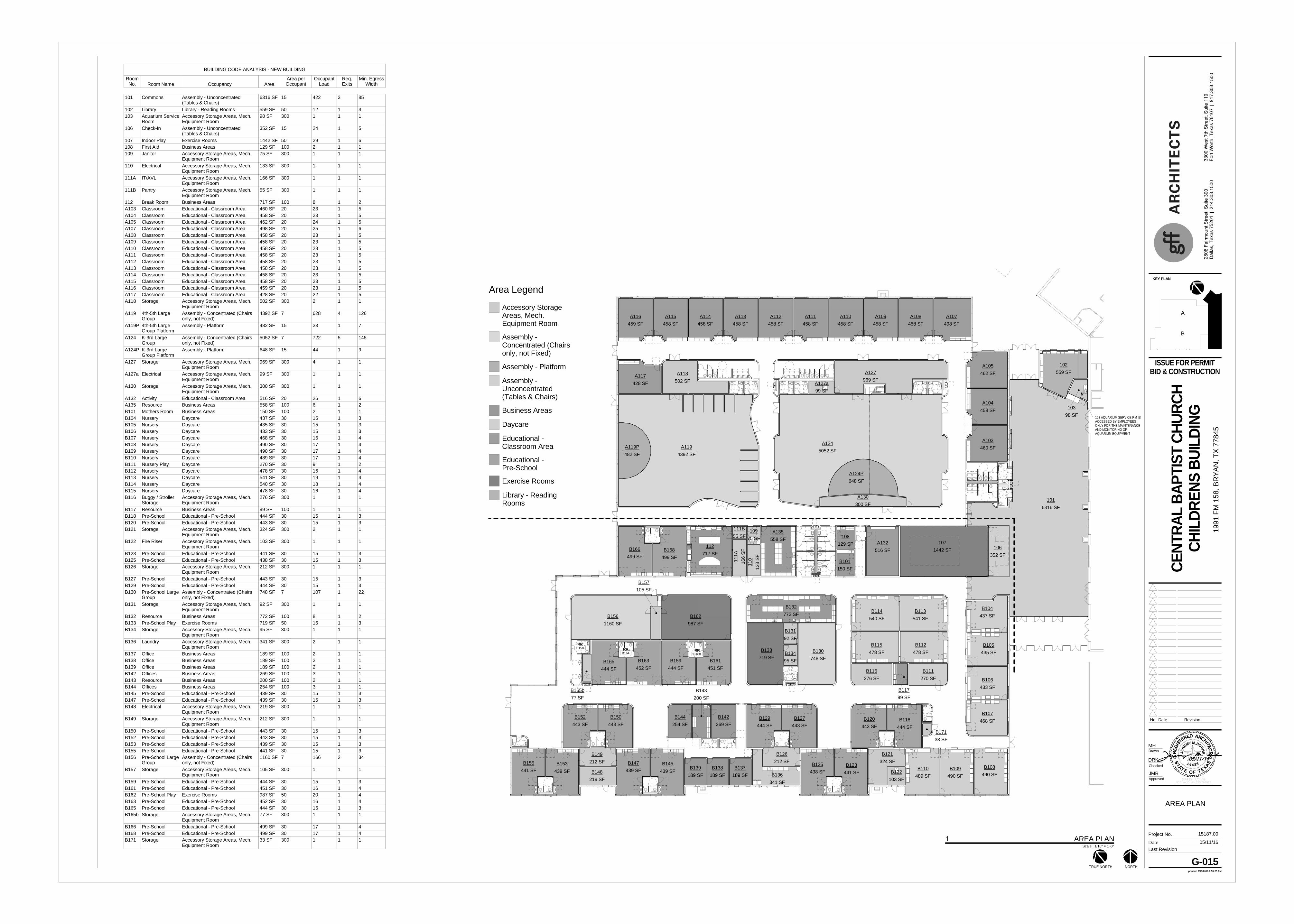
Area Legend
Accessory StorageAreas, Mech.Equipment Room
Assembly -Concentrated (Chairsonly, not Fixed)
Assembly - Platform
Assembly -Unconcentrated(Tables & Chairs)
Business Areas
Daycare
Educational -Classroom Area
Educational -Pre-School
Exercise Rooms
Library - ReadingRooms
437 SFB104
435 SFB105
433 SFB106
468 SFB107
490 SFB108
490 SFB109
489 SFB110
270 SFB111
541 SFB113
478 SFB112
478 SFB115
540 SFB114
99 SFB117
772 SFB132
200 SFB143
558 SFA135
129 SF108
150 SFB101
189 SFB137
189 SFB138
189 SFB139
269 SFB142
254 SFB144
1442 SF107
748 SFB130
4392 SFA119
5052 SFA124
428 SFA117
459 SFA116
458 SFA115
458 SFA114
458 SFA113
458 SFA112
458 SFA111
458 SFA110
458 SFA109
458 SFA108
498 SFA107
462 SFA105
458 SFA104
460 SFA103
516 SFA132
499 SFB168
499 SFB166
719 SFB133
444 SFB118
443 SFB120
441 SFB123
438 SFB125
443 SFB127
444 SFB129
443 SFB150
443 SFB152
439 SFB145
439 SFB147
439 SFB153
441 SFB155
717 SF112
502 SFA118
969 SFA127
300 SFA130
75 SF109
133
SF11
016
6 SF
111A
92 SFB131
95 SFB134
276 SFB116
324 SFB121
103 SFB122
212 SFB126
341 SFB136
212 SFB149
98 SF103
559 SF102
6316 SF101
219 SFB148
352 SF106
99 SFA127a
482 SFA119P
648 SFA124P
55 SF111B
33 SFB171
RRB164
RRB160
RRB158
444 SFB165
77 SFB165b
105 SFB157
452 SFB163
444 SFB159
451 SFB161
987 SFB162
1160 SFB156
103 AQUARIUM SERVICE RM ISACCESSED BY EMPLOYEESONLY FOR THE MAINTENANCEAND MONITORING OFAQUARIUM EQUIPMENT
EXPIRES: 7/31/16
NOT VALID UNLESS SIGNED
AT
TS
XETE FO
SA
JERE
MYM.ROEHR
2 4 4 25
REG
IS
TERED ARCHITEC
T
Last RevisionDate
Project No.
Approved
Checked
Drawn
printedTRUE NORTH NORTH
KEY PLAN
B
A
No. Date Revision
280 8
Fai
rmou
nt S
treet
, Sui
te 3
0 033
0 0 W
est 7
th S
t reet
, Su i
te 1
10D
alla
s, T
exas
752
01 |
214
.303
.150
0Fo
r t W
orth
, Tex
as 7
6107
| 8
17.3
03.1
5 00
5/13/2016 1:59:25 PM
AREA PLAN
G-015
ISSUE FOR PERMITBID & CONSTRUCTION
CENT
RAL
BAPT
IST
CHUR
CHCH
ILDR
ENS
BUIL
DING
1991
FM
158
, BR
YAN
, TX
7784
5
15187.00
JMR
DRK
MH
05/11/16
05/11/16
Scale: 1/16" = 1'-0"
1 AREA PLAN
BUILDING CODE ANALYSIS - NEW BUILDING
RoomNo. Room Name Occupancy Area
Area perOccupant
OccupantLoad
Req.Exits
Min. EgressWidth
101 Commons Assembly - Unconcentrated(Tables & Chairs)
6316 SF 15 422 3 85
102 Library Library - Reading Rooms 559 SF 50 12 1 3103 Aquarium Service
RoomAccessory Storage Areas, Mech.Equipment Room
98 SF 300 1 1 1
106 Check-In Assembly - Unconcentrated(Tables & Chairs)
352 SF 15 24 1 5
107 Indoor Play Exercise Rooms 1442 SF 50 29 1 6108 First Aid Business Areas 129 SF 100 2 1 1109 Janitor Accessory Storage Areas, Mech.
Equipment Room75 SF 300 1 1 1
110 Electrical Accessory Storage Areas, Mech.Equipment Room
133 SF 300 1 1 1
111A IT/AVL Accessory Storage Areas, Mech.Equipment Room
166 SF 300 1 1 1
111B Pantry Accessory Storage Areas, Mech.Equipment Room
55 SF 300 1 1 1
112 Break Room Business Areas 717 SF 100 8 1 2A103 Classroom Educational - Classroom Area 460 SF 20 23 1 5A104 Classroom Educational - Classroom Area 458 SF 20 23 1 5A105 Classroom Educational - Classroom Area 462 SF 20 24 1 5A107 Classroom Educational - Classroom Area 498 SF 20 25 1 6A108 Classroom Educational - Classroom Area 458 SF 20 23 1 5A109 Classroom Educational - Classroom Area 458 SF 20 23 1 5A110 Classroom Educational - Classroom Area 458 SF 20 23 1 5A111 Classroom Educational - Classroom Area 458 SF 20 23 1 5A112 Classroom Educational - Classroom Area 458 SF 20 23 1 5A113 Classroom Educational - Classroom Area 458 SF 20 23 1 5A114 Classroom Educational - Classroom Area 458 SF 20 23 1 5A115 Classroom Educational - Classroom Area 458 SF 20 23 1 5A116 Classroom Educational - Classroom Area 459 SF 20 23 1 5A117 Classroom Educational - Classroom Area 428 SF 20 22 1 5A118 Storage Accessory Storage Areas, Mech.
Equipment Room502 SF 300 2 1 1
A119 4th-5th LargeGroup
Assembly - Concentrated (Chairsonly, not Fixed)
4392 SF 7 628 4 126
A119P 4th-5th LargeGroup Platform
Assembly - Platform 482 SF 15 33 1 7
A124 K-3rd LargeGroup
Assembly - Concentrated (Chairsonly, not Fixed)
5052 SF 7 722 5 145
A124P K-3rd LargeGroup Platform
Assembly - Platform 648 SF 15 44 1 9
A127 Storage Accessory Storage Areas, Mech.Equipment Room
969 SF 300 4 1 1
A127a Electrical Accessory Storage Areas, Mech.Equipment Room
99 SF 300 1 1 1
A130 Storage Accessory Storage Areas, Mech.Equipment Room
300 SF 300 1 1 1
A132 Activity Educational - Classroom Area 516 SF 20 26 1 6A135 Resource Business Areas 558 SF 100 6 1 2B101 Mothers Room Business Areas 150 SF 100 2 1 1B104 Nursery Daycare 437 SF 30 15 1 3B105 Nursery Daycare 435 SF 30 15 1 3B106 Nursery Daycare 433 SF 30 15 1 3B107 Nursery Daycare 468 SF 30 16 1 4B108 Nursery Daycare 490 SF 30 17 1 4B109 Nursery Daycare 490 SF 30 17 1 4B110 Nursery Daycare 489 SF 30 17 1 4B111 Nursery Play Daycare 270 SF 30 9 1 2B112 Nursery Daycare 478 SF 30 16 1 4B113 Nursery Daycare 541 SF 30 19 1 4B114 Nursery Daycare 540 SF 30 18 1 4B115 Nursery Daycare 478 SF 30 16 1 4B116 Buggy / Stroller
StorageAccessory Storage Areas, Mech.Equipment Room
276 SF 300 1 1 1
B117 Resource Business Areas 99 SF 100 1 1 1B118 Pre-School Educational - Pre-School 444 SF 30 15 1 3B120 Pre-School Educational - Pre-School 443 SF 30 15 1 3B121 Storage Accessory Storage Areas, Mech.
Equipment Room324 SF 300 2 1 1
B122 Fire Riser Accessory Storage Areas, Mech.Equipment Room
103 SF 300 1 1 1
B123 Pre-School Educational - Pre-School 441 SF 30 15 1 3B125 Pre-School Educational - Pre-School 438 SF 30 15 1 3B126 Storage Accessory Storage Areas, Mech.
Equipment Room212 SF 300 1 1 1
B127 Pre-School Educational - Pre-School 443 SF 30 15 1 3B129 Pre-School Educational - Pre-School 444 SF 30 15 1 3B130 Pre-School Large
GroupAssembly - Concentrated (Chairsonly, not Fixed)
748 SF 7 107 1 22
B131 Storage Accessory Storage Areas, Mech.Equipment Room
92 SF 300 1 1 1
B132 Resource Business Areas 772 SF 100 8 1 2B133 Pre-School Play Exercise Rooms 719 SF 50 15 1 3B134 Storage Accessory Storage Areas, Mech.
Equipment Room95 SF 300 1 1 1
B136 Laundry Accessory Storage Areas, Mech.Equipment Room
341 SF 300 2 1 1
B137 Office Business Areas 189 SF 100 2 1 1B138 Office Business Areas 189 SF 100 2 1 1B139 Office Business Areas 189 SF 100 2 1 1B142 Offices Business Areas 269 SF 100 3 1 1B143 Resource Business Areas 200 SF 100 2 1 1B144 Offices Business Areas 254 SF 100 3 1 1B145 Pre-School Educational - Pre-School 439 SF 30 15 1 3B147 Pre-School Educational - Pre-School 439 SF 30 15 1 3B148 Electrical Accessory Storage Areas, Mech.
Equipment Room219 SF 300 1 1 1
B149 Storage Accessory Storage Areas, Mech.Equipment Room
212 SF 300 1 1 1
B150 Pre-School Educational - Pre-School 443 SF 30 15 1 3B152 Pre-School Educational - Pre-School 443 SF 30 15 1 3B153 Pre-School Educational - Pre-School 439 SF 30 15 1 3B155 Pre-School Educational - Pre-School 441 SF 30 15 1 3B156 Pre-School Large
GroupAssembly - Concentrated (Chairsonly, not Fixed)
1160 SF 7 166 2 34
B157 Storage Accessory Storage Areas, Mech.Equipment Room
105 SF 300 1 1 1
B159 Pre-School Educational - Pre-School 444 SF 30 15 1 3B161 Pre-School Educational - Pre-School 451 SF 30 16 1 4B162 Pre-School Play Exercise Rooms 987 SF 50 20 1 4B163 Pre-School Educational - Pre-School 452 SF 30 16 1 4B165 Pre-School Educational - Pre-School 444 SF 30 15 1 3B165b Storage Accessory Storage Areas, Mech.
Equipment Room77 SF 300 1 1 1
B166 Pre-School Educational - Pre-School 499 SF 30 17 1 4B168 Pre-School Educational - Pre-School 499 SF 30 17 1 4B171 Storage Accessory Storage Areas, Mech.
Equipment Room33 SF 300 1 1 1
Area Legend
AccessoryStorage Areas,Mech. EquipmentRoom
Assembly -Concentrated(Chairs only, notFixed)
Assembly -Platform
Assembly -Unconcentrated(Tables & Chairs)
Business Areas
Daycare
Educational -Classroom Area
Educational -Pre-School
Exercise Rooms
Library - ReadingRooms
437 SFB104
435 SFB105
433 SFB106
468 SFB107
490 SFB108
490 SFB109
489 SFB110
270 SFB111
541 SFB113
478 SFB112
478 SFB115
540 SFB114
99 SFB117
772 SFB132
200 SFB143
558 SFA135
129 SF108
150 SFB101
189 SFB137
189 SFB138
189 SFB139
269 SFB142
254 SFB144
1442 SF107
748 SFB130
4392 SFA119
5052 SFA124
428 SFA117
459 SFA116
458 SFA115
458 SFA114
458 SFA113
458 SFA112
458 SFA111
458 SFA110
458 SFA109
458 SFA108
498 SFA107
462 SFA105
458 SFA104
460 SFA103
516 SFA132
499 SFB168
499 SFB166
719 SFB133
444 SFB118
443 SFB120
441 SFB123
438 SFB125
443 SFB127
444 SFB129
443 SFB150
443 SFB152
439 SFB145
439 SFB147
439 SFB153
441 SFB155
717 SF112
502 SFA118
969 SFA127
300 SFA130
75 SF109
133 SF110
166 SF111A
92 SFB131
95 SFB134
276 SFB116
324 SFB121
103 SFB122
212 SFB126
341 SFB136
212 SFB149
98 SF103
559 SF102
6316 SF101
219 SFB148
352 SF106
99 SFA127a
411
11
1
2429
2
1
1
1
8
23
23
24
25232323232323232323
22
2
635724
4
1
1
276
2
16
15
15
16
171717
10
16
1919
16
1
1
15
15
2
1
15
15
1
1515
109
1
8
15
1
2
222
3
23
1515
1
1
1515
15
15
17 17
330
169
169
192
193 192
192
5
14
15
193
361 127
257
5
4
330
164
330
NON-SIMULTANEOUS USE- PRE FUNCTION AREA
482 SFA119P
648 SFA124P
33
44
668768
217
218
238
238
297
297
NON-SIMULTANEOUSUSE
REFER TO 2/G-016 FOR EXISTINGBUILDING EXITING
16 16
17
1655
55
4 4
46
45
313831
4
8
8
41
40
230
42
185 94
247
190
297
1492
1308
330185
330247
1651
330297
330330
330330
330330 165
165
330
277 277 278
832
660
660
330327
330327
330327
330327
330330
EXIT #
CLEAR WIDTH PROVIDEDOCC. MAX
1
132"660
EXIT #
CLEAR WIDTH PROVIDEDOCC. MAX
2
32"165
EXIT #
CLEAR WIDTH PROVIDEDOCC. MAX
3
66"330
EXIT #
CLEAR WIDTH PROVIDEDOCC. MAX
4
66"330
EXIT #
CLEAR WIDTH PROVIDEDOCC. MAX
5
66"330
EXIT #
CLEAR WIDTH PROVIDEDOCC. MAX
6
66"330
EXIT #
CLEAR WIDTH PROVIDEDOCC. MAX
7
66"330
EXIT #
CLEAR WIDTH PROVIDEDOCC. MAX
8
33"165
1651
EXIT #
CLEAR WIDTH PROVIDEDOCC. MAX
9
33"165
EXIT #
CLEAR WIDTH PROVIDEDOCC. MAX
10
66"330
EXIT #
CLEAR WIDTH PROVIDEDOCC. MAX
11
264"1320
*WORST CASE SCENARIO SHOWNLARGE GROUP SPACES ARE
ACCESSORY TO CLASSROOMSNON-SIMILTANEOUS USE
*WORST CASE SCENARIO SHOWNLARGE GROUP SPACES ARE
ACCESSORY TO CLASSROOMSNON-SIMILTANEOUS USE
*WORST CASE SCENARIO SHOWNLARGE GROUP SPACE IS
ACCESSORY TO CLASSROOMS.NON-SIMILTANEOUS USE
*EXPECTED OCCUPANCY LESS THAN 350BASED ON CLASSROOM OCCUPANCY COUNTS,
BUT MAX SHOWN FOR LIFE SAFETY PLAN
*NON-SIMILTANEOUSUSE WITH A124
*NON-SIMILTANEOUSUSE WITH A124
*NON-SIMILTANEOUSUSE WITH A124
*NON-SIMILTANEOUSUSE WITH A124
*NON-SIMILTANEOUSUSE WITH A124
*NON-SIMILTANEOUSUSE WITH A124
*NON-SIMILTANEOUSUSE WITH A124
*NON-SIMILTANEOUSUSE WITH A124
*NON-SIMILTANEOUSUSE WITH A124
*NON-SIMILTANEOUSUSE WITH A124
*NON-SIMILTANEOUSUSE WITH A124
*NON-SIMILTANEOUSUSE WITH A124
*NON-SIMILTANEOUSUSE WITH A124
*NON-SIMILTANEOUSUSE WITH A124
165
11
330
330330
164
328
47
47
1
FEC FEC
FEC
FEC
FEC
FEC FEC
FEC
FEC
FEC
FEC FEC
FEC
FEC
FEC
FEC
FEC
1160 SFB156
987 SFB162105 SF
B157
77 SFB165b
444 SFB165
452 SFB163
444 SFB159
451 SFB161
1516
1
15 16
20
1
166
16
10
10
84
83
5
5
41
103 AQUARIUM SERVICE RM ISACCESSED BY EMPLOYEESONLY FOR THE MAINTENANCEAND MONITORING OFAQUARIUM EQUIPMENT
0
0
00
LIFE SAFETY NOTES
OCCUPANT LOAD LEGEND
1. REFER TO MECHANICAL DRAWINGS FOR ANY FIRE AND SMOKEDAMPERS IN DUCTWORK
2. REFER TO ELECTRICAL DRAWINGS FOR ANY LOCATIONS OF FIREALARM DEVICES
3. REFER TO PLUMBING DRAWINGS FOR STANDPIPE AND AUTOMATICSPRINKLER SYSTEM INFORMATION
4. REFER TO REFLECTED CEILING PLAN AND ELECTRICAL DRAWINGSFOR LOCATIONS OF EXIT AND EMERGENCY LIGHTING
5. FIRE-RATED PARTITIONS ARE DESIGNATED ON THE LIFE SAFETYPLAN. OTHER NON-RATED PARTITIONS CONSTRUCTED TOPROVIDE SOUND INSULATION OR OTHER FUNCTIONAL PURPOSESDO NOT REQUIRE OPENING PROTECTION
6. EVERY ROOM OR SPACE THAT IS AN ASSEMBLY OCCUPANCYSHALL HAVE THE OCCUPANT LOAD OF THE ROOM OR SPACEPOSTED IN A CONSPICUOUS PLACE, NEAR THE MAIN EXIT OR EXITACCESS DOORWAY FROM THE ROOM OR SPACE. POSTED SIGNSSHALL BE OF AN APPROVED LEGIBLE PERMANENT DESIGN AND
SHALL BE MAINTAINED BY THE OWNER OR AUTHORIZED AGENT.
OCCUPANT LOAD NUMBER PER ROOM/SPACE
AGGREGATE OCCUPANT LOAD NUMBER
AGGREGATE OCCUPANT LOAD PER EXITALLOWABLE OCCUPANT LOAD PER EXIT
PLATFORM299 OCC.
REHEARSAL313 OCC.
EXISTING SANCTUARY SEATING3,479 OCC.
EXISTING EDUCATION WING:83 OCC. (1ST FLOOR) EXITINGTO COMMONS
ALL OTHER OCCUPANTS EXITDIRECTLY TO EXTERIOR
EXISTING EDUCATION / OFFICE WING101 OCC. (1ST FLOOR) EXITINGTO COMMONS
139 OCC. FROM 2ND FLOOREXITING DIRECTLY TO EXTERIOR
83
156 156
149 150289 290
580 580
580 580
580
101
911
594
*INFORMATION ON EXISTING BUILDING TAKEN FROM PERMITTED DRAWING SET (2002)
EXPIRES: 7/31/16
NOT VALID UNLESS SIGNED
AT
TS
XETE FO
SA
JERE
MYM.ROEHR
2 4 4 25
REG
IS
TERED ARCHITEC
T
Last RevisionDate
Project No.
Approved
Checked
Drawn
printed
KEY PLAN
B
A
No. Date Revision
280 8
Fai
rmou
nt S
treet
, Sui
te 3
0 033
0 0 W
est 7
th S
t reet
, Su i
te 1
10D
alla
s, T
exas
752
01 |
214
.303
.150
0Fo
r t W
orth
, Tex
as 7
6107
| 8
17.3
03.1
5 00
5/13/2016 1:59:38 PM
LIFE SAFETYPLAN
G-016
ISSUE FOR PERMITBID & CONSTRUCTION
CENT
RAL
BAPT
IST
CHUR
CHCH
ILDR
ENS
BUIL
DING
1991
FM
158
, BR
YAN
, TX
7784
5
15187.00
JMR
DRK
MH
05/11/16
05/11/16
Scale: 3/32" = 1'-0"
1 LIFE SAFETY PLAN
Scale: 1" = 100'-0"
2 EXITING PLAN - EXISTING