Embed Size (px)
Citation preview

TABLE OF CONTENTS
Part I. Introduction . . . . . . . . . . . . . . . . . . . . . . . . . . . . . . . . . . . . . . . . . . . . . . . . .2
Part II. Pre-Trip Car Inspection . . . . . . . . . . . . . . . . . . . . . . . . . . . . . . . . . . . . . . . .4
Part III. Air Requirements . . . . . . . . . . . . . . . . . . . . . . . . . . . . . . . . . . . . . . . . . . . . .5
Part IV. Operating Instructions . . . . . . . . . . . . . . . . . . . . . . . . . . . . . . . . . . . . . . . .6
Operating Controls . . . . . . . . . . . . . . . . . . . . . . . . . . . . . . . . . . . . . . . .6
General Unloading Instructions . . . . . . . . . . . . . . . . . . . . . . . . . . . . . . .7
Hook-up . . . . . . . . . . . . . . . . . . . . . . . . . . . . . . . . . . . . . . . . . . . . . . . .8
Pressurization . . . . . . . . . . . . . . . . . . . . . . . . . . . . . . . . . . . . . . . . . . . .8
Unloading . . . . . . . . . . . . . . . . . . . . . . . . . . . . . . . . . . . . . . . . . . . . . . .9
Unloading Assists (Vibration and Fluidization) . . . . . . . . . . . . . . . . . . .9
Part V. General Maintenance . . . . . . . . . . . . . . . . . . . . . . . . . . . . . . . . . . . . . . . . .10
Pressure Gauges . . . . . . . . . . . . . . . . . . . . . . . . . . . . . . . . . . . . . . . . . .10
Rupture Disc . . . . . . . . . . . . . . . . . . . . . . . . . . . . . . . . . . . . . . . . . . . . .11
Pressure Relief Valves . . . . . . . . . . . . . . . . . . . . . . . . . . . . . . . . . . . . . .12
Hatches . . . . . . . . . . . . . . . . . . . . . . . . . . . . . . . . . . . . . . . . . . . . . . . . .13
Part VI. Cleaning . . . . . . . . . . . . . . . . . . . . . . . . . . . . . . . . . . . . . . . . . . . . . . . . . . . . .15
Part VII. Troubleshooting . . . . . . . . . . . . . . . . . . . . . . . . . . . . . . . . . . . . . . . . . . . . . .16
Part VIII. Parts List . . . . . . . . . . . . . . . . . . . . . . . . . . . . . . . . . . . . . . . . . . . . . . . . . . . . .19
Part IX. Specification Sheet . . . . . . . . . . . . . . . . . . . . . . . . . . . . . . . . . . . . . . . . . . . .24
CENTER FLOW ® PRESSUREAIDE® CAR
1
PAGE
QUICK RELEASE CAM LEVER
GASKETCOVER
PRESSURE-TIGHT LOADING HATCHFOR PRESSURE DIFFERENTIAL CAR
Length Over Strikers 56’-11” 56’-11” 62’-5 1/4” 62’-5 1/4”Truck Centers 46’-3” 46’-3” 51’-9 1/4” 51’-9 1/4”Overall Height 15’-6” 15’-4 13/16” 15’-5 9/16” 15’-5 9/16”Overall Width 10’-7 3/16” 10’-6” 10’-3” 10’-3”Height Rail to Bottom
of Discharge Outlets (Light Car) 12 13/16” 12 13/16” 13” 13”Number of Hoppers 4 4 4 4 Number of Outlets per Hopper 1 1 1 1 Number of Roof Hatches 8 8 8 8 Size of Roof Hatches 20” Dia. 20” Dia. 20” Dia. 20” Dia.Slope End Floor Sheet 50º-45º 50º-43º 50º-43º 43º-45ºSlope Interior Floor Sheet 50º 50º-45º 50º-45º 43º-45ºSlope Side Slope Sheet 45º 45º 45º 51ºCubic Capacity 5000 cu. ft. 5000 cu. ft. 5300 cu. ft. 5750 cu. ft.Estimated Nominal Lightweight 72,000 lbs 66,900 lbs. 70,300 lbs. 70,100 lbsHorizontal Curve Negotiability -
Uncoupled 150 ft. 150 ft. 180 ft. 180 ft.
3" BLOWDOWN VALVE
PRESSURE GAGES
12"
COUPLER PULLING FACE
SHPX
BASIC SPECIFICATIONS 5000 5001 5003 5007
24
PART IX.
SPECIFICATION SHEETCENTER FLOW ® PRESSUREAIDE® CAR

PART I.
INTRODUCTION
The ARL Pressureaide® pressure differential Center Flow® covered hopper car is designed to handledry bulk commodities. With operating pressures up to 14.5 psig, fast, efficient unloading for longdistances can be achieved. Unloading rates up to 100,000 lbs/hour may be obtained dependingupon the commodity and unloading system.
The Pressureaide® car has many of the famous Center Flow® car design features: centerline load-ing, unloading, complete sanitation and ease of operation. Designed to operate with standard positive displacement blowers, this car may be used with equipment compatible with pressuresleds. As safety is a prime consideration for American Railcar Leasing LLC, the Pressureaide® caris equipped with two pressure relief valves, a rupture disc and a vacuum relief valve.
The Pressureaide® car is unmatched by any railcar in its class when it comes to sanitation, mainte-nance and unloading performance.
Figure 1. Center Flow® Pressureaide® Car
2
CENTER FLOW ® PRESSUREAIDE® CAR
NOTE: For replacement of rupture disc only, (Reference Page 11 - Figure 14 of this manual for serv-ice and repair procedure) order Rupture Disc Replacement Kit per Key No. 29.
* For Cars Built Before January 2000** For Cars Built In January of 2000 And Later
2 8 Cam Lever Assy. at Safety Catch 5W107206 5-W-1072-063 40 Cam Lever Assy. 5W107205 5-W-1072-054 8 Gasket For Hatch Cover For Retainer Type 90011238 ---4A 8 Gasket For Hatch Cover Without Retainer 90038668 3-K-73295 8 Gasket Retainer 50093367 ---6 48 Cap Screw 90018658 ---7 48 Shakeproof Washer 90004405 ---8 8 Hinge Pin 50092946 2-K-89619 16 Washer 90004404 ---10 8 Cotter Pin 90007113 ---11 8 Cover (Includes Gasket) 50091016 4-U-432612 8 Safety Catch 50092947 3-K-8981-0013 1 2” Pressure Relief Valve Without Elbow 57333505 or 57334111 2-J-3995 or 2-V-536314 1 Vacuum Relief Valve 57333907 3-J-2077-0115 1 Blowdown Valve Assy. 57333754* ---15 A 1 Blowdown Valve Assy. 57334107** 3-V-807316 2 Tubing - Meter Box 25’ Section 91002188 ---17 2 Pressure Gauge 50093321* 1-J-268517A 2 Pressure Gauge 50091480** 1-V-546518 1 Gauge Cover 50093290* 11-8204318A 1 Gauge Cover 2V610400** 2-V-610419 1 Rupture Disc Assy. Includes
Key Nos. 20 Through 28 50093602 3-J-561220 1 Lead Wire Seal --- ---21 1 Wire --- ---22 4 Stop Nut --- ---23 4 Washer S. S. --- ---24 1 Rupture Disc Valve Cover --- ---25 4 Hex Nut --- ---26 1 Rupture Disc Holder --- ---27 1 Rupture Disc --- ---28 4 Bolt With Seal Hole --- ---29 1 Rupture Disc Replacement Kit Includes
Key Nos. 20, 21 and 27 50093596 2-J-5615
KEYNUMBERPER UNIT DESCRIPTION CATALOG NUMBER DRAWING NUMBER
23
Parts List
CENTER FLOW ® PRESSUREAIDE® CAR

8'-3 1/2" 6'-4" 5'-4 1/4" 5'-0" 5'-0" 5'-0" 5'-4 1/4" 6'-4" 8'-3 1/2"
6'-5 1/2" 9'-1" 5'-4 1/4" 6'-3"6'-2 3/16" 6'-3" 5'-4 1/4" 9'-1" 6'-5 1/2"
Figure 2 shows the standard roof hatch and bulkhead arrangement for the models 5000 and 5001Pressureaide® cars. Each compartment has two hatches located on the car’s longitudinal centerline.Intermediate bulkheads are designed to permit simultaneous loading of adjacent compartmentsfrom one hatch.
Figure 3 shows the standard roof hatch and bulkhead arrangement for the models 5003 and 5007Pressureaide® cars. Each compartment has two hatches located on the car’s longitudinal centerline.Intermediate bulkheads are designed to permit simultaneous loading of adjacent compartments fromone hatch.
Figure 3. Standard 8-Hatch Arrangement For Models 5003 and 5007
Figure 2. Standard 8-Hatch Arrangement For Models 5000 and 5001
3
CENTER FLOW ® PRESSUREAIDE® CAR
SE
E D
ETA
IL ’A
’
DE
TAIL
’A’
SE
E D
ETA
IL ’C
’
’A’ E
ND
OF
CA
R
SE
E D
ETA
IL ’B
’
DE
TAIL
’B’
DE
TAIL
’C’
IDE
NT
IFIC
AT
ION
TA
G
INC
L. K
EY
NO
S.
20 T
HR
U 2
8
CA
UT
ION
:S
UB
ST
ITU
TIO
N O
R M
AK
ES
HIF
TD
ISC
S A
RE
NO
T T
O B
E U
SE
D.
US
E O
NLY
20
PS
IG D
ISC
S.
12
4 4A5
67
89
1011
23
1515A
19
14
13
1717A
1818A
16
1920
21
29
22 23 24 25
27 26
28
22
PART VIII.
PARTS LISTCENTER FLOW ® PRESSUREAIDE® CAR
PRE-TRIP CHECKLIST
BEFORE LOADING
1. If the car is to be cleaned, follow the proce-dures on page 15.
2. Ensure there is no water in the air manifoldand that the product manifold and membranesare clean and dry.
3. Inspect all hatch covers, locking mechanismsand safety catches for proper operation. Ensuregaskets are clean and in good condition.
4. Inspect and operate all control valves (prod-uct, by-pass air, fluidizing air and blowdown) toensure they are in proper working condition.
5. Inspect all dust caps. Ensure gaskets are inplace and in good condition. Attachment chainsand cam levers must be intact.
6. Inspect pressure gauges and protective cov-ers. Be sure the gauges read zero with cardepressurized and the cover is not broken.
7. Inspect all rubber hoses to ensure the hoseclamps are properly installed and tightened andthat the hoses are intact.
8. If the cleanout port has a flanged cover,ensure its gasket is properly installed and allfasteners properly tightened. If the cleanoutport has a dust cap arrangement, ensure the capis properly installed, its gasket is in good condi-tion and a proper locking seal is applied to theoperating levers.
9. Ensure all valves are closed prior to loadingproduct into the car. If venting is required, itmay be provided for by opening the blowdownvalve or a hatch. Proper filters may be requiredto minimize dusting.
AFTER LOADING
1. Check all caps for secure installation.
2. Ensure blowdown valve is closed.
3. Ensure cover over pressure gauges is closed.
4. All hatches must be closed and all hold-downs properly engaged in the closed position.
PART II.
PRE-TRIP CAR INSPECTION
PRESSURE RELIEF VALVE, RUPTURE DISC,VACUUM RELIEF VALVE LOCATED ON ROOF
BLOWDOWN VALVE
PRESSURE GAGES
CLEAN-OUT PORT
BY-PASS AIR VALVE
MANIFOLD PRESSURERELIEF VALVE
AIR INLET(FAR SIDE)
FLUIDIZING AIR VALVES
PRODUCTVALVE
FLUIDIZING AIR VAVLES
SIDE SILLBY-PASS AIR VALVE
CLEAN-OUT PORT
AIR INLET(NEAR SIDE)PRODUCT
DISCHARGE
"A"Comp.
"AC"Comp.
"BC"Comp.
"B"Comp.
Figure 4. Operating Equipment
The Pressureaide® car is a special piece of equipment, as such, it requires regular preventativemaintenance. Part of this program includes a thorough pre-trip inspection prior to loading.
“A” END
“B” END
4
CENTER FLOW ® PRESSUREAIDE® CAR
MOUNTING FRAME FLANGE
SEE VIEW 'A'
VIEW LOOKING UPAT MEMBRANE
7
65
3
4
22A
1
VIEW 'A'
4
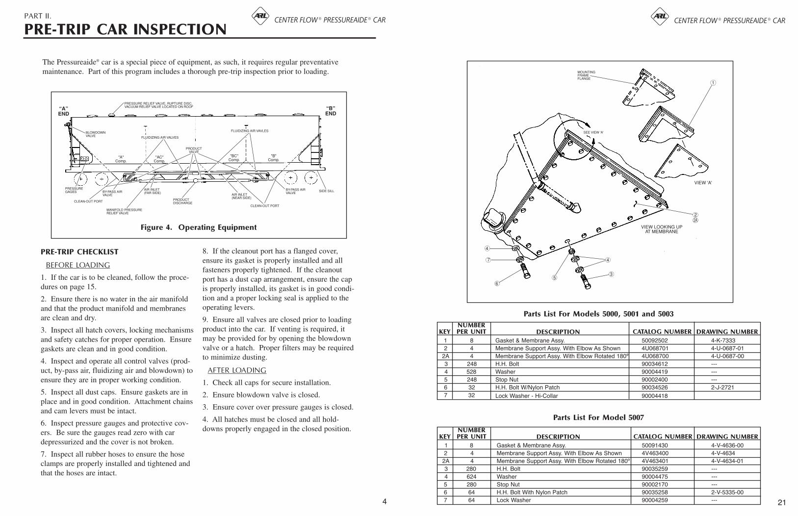
1 8 Gasket & Membrane Assy. 50092502 4-K-73332 4 Membrane Support Assy. With Elbow As Shown 4U068701 4-U-0687-01
2A 4 Membrane Support Assy. With Elbow Rotated 180º 4U068700 4-U-0687-003 248 H.H. Bolt 90034612 ---4 528 Washer 90004419 ---5 248 Stop Nut 90002400 ---6 32 H.H. Bolt W/Nylon Patch 90034526 2-J-27217 32 Lock Washer - Hi-Collar 90004418
KEYNUMBERPER UNIT DESCRIPTION CATALOG NUMBER DRAWING NUMBER
1 8 Gasket & Membrane Assy. 50091430 4-V-4636-002 4 Membrane Support Assy. With Elbow As Shown 4V463400 4-V-4634
2A 4 Membrane Support Assy. With Elbow Rotated 180º 4V463401 4-V-4634-013 280 H.H. Bolt 90035259 ---4 624 Washer 90004475 ---5 280 Stop Nut 90002170 ---6 64 H.H. Bolt With Nylon Patch 90035258 2-V-5335-007 64 Lock Washer 90004259 ---
KEYNUMBERPER UNIT DESCRIPTION CATALOG NUMBER DRAWING NUMBER
Parts List For Models 5000, 5001 and 5003
Parts List For Model 5007
21
CENTER FLOW ® PRESSUREAIDE® CAR

PART III.
AIR REQUIREMENTS
The Pressureaide® car has been designed tooperate with air supplies from 200 CFM to 1000CFM (CFM=Cubic Feet Per Minute).
The air requirement for a particular systemdepends on the diameter and configuration ofthe conveying line and the characteristics of thematerial being conveyed. To determine the airrequirements for a specific unloading system,furnish your ARL representative with thedetails of the system. As a general guide forair requirements in low-pressure pneumatic sys-tems, refer to the following chart:
CAUTION: UNDER NO CIRCUMSTANCES SHOULD
MORE THAN 1000 CFM BE USED TOPRESSURIZE THE CAR NOR SHOULD
CAR PRESSURE EXCEED 14.5 PSIG.
Best results are obtained by using a positive dis-placement blower which will develop air flow(CFM) at a minimum of 14.5 psig. However,there are many other types of blowers and aircompressors that produce adequate air flow tooperate the Pressureaide® car.
Large industrial plant systems, which producean adequate air flow, may be used to operate thePressureaide® car provided they are equippedwith a pressure regulator that limits the pressureto 20 psig, an adequate water trap and a goodfilter.
NOTE: WHEN USING ANY AIR SOURCE, THE AIR
MUST BE CLEAN, FREE FROM OIL ANDWATER AND ITS TEMPERATURE MUST
NOT EXCEED 250ºF. FAILURE TO DO SO MAY RESULT IN DAMAGE TO THE
CAR’S MEMBRANES.
The Pressureaide® car has two membranes in thebottom of each compartment. Air directedthrough the membranes fluidizes the lading andpressurizes the car. The fluidization breaksdown the internal strength of the lading and thepressurization provides the energy to convey thelading.
To ensure the system works properly, the airinlet side of the membranes must remain clean.This requires that precautions be taken at theunloading site:
1.) Air inlet hose must be free of product and/orother foreign material.
2.) Air supply should be clean and dry.
In situations where by-pass air lines are used(see Figure 5) a check valve and metering valvearrangement should be part of the system. Thepurpose of the metering valve is to permit prop-er adjustment of air flow into and by the car,while the check valve is to ensure against abackflow of lading into the blower package andthe car’s air inlet line in the event the air supplyis interrupted during the unloading process.
Unloading systems utilizing automation are spe-cial cases. If the unloading system uses auto-mated controls, contact an ARL representative.Potentially undesirable situations may be avoid-ed after a brief review of the railcar and its rela-tionship with the system.
PRODUCT LINESIZE
4-inch (pipe) . . . . . . . .440 CFM5-inch (pipe) . . . . . . . .680 CFM6-inch (pipe) . . . . . . .1000 CFM
AIRVOLUME
BYPASS LINE
METERING VALVE
CHECK VALVE
PRODUCT DISCHARGE
PRESSUREAIDE® CAR
AIR INLET
BLOWER PACKAGE
TO STORAGE BIN
Figure 5. Product Discharge With By-Pass
5
CENTER FLOW ® PRESSUREAIDE® CAR
1 6 5” Alum. KamLok Cap 50093980 ---
2 6 Gasket - 5” KamLok Cap 90038105 ---
3 2 Hose 4 1/2” I.D. x 8 1/2” 50093438 2-J-3768-00
4 8 Hose Clamp - 5 1/8” 50093460 2-V-6794-01
5 2 4” Alum. KamLok Cap 50093981 ---
6 2 Gasket - 4” KamLok Cap 90038100 ---
7 12 Gasket - 5” Manifold 90038085 2-J-4059
8 4 Four-Way Valve 6J599700 6-J-5997
9 4 Valve Repair Kit 3V469500 3-V-4695
10 1 5” Cross - Alum. 5J979700 5-J-9797
11 4 Hose 5 9/16” I.D. x 8 1/2” 50093465 1-J-3336-01
12 8 Hose Clamp - 6 1/8” 50093464 2-V-6794-02
13 8 Hose 2 3/8” I.D. x 15 5/16” 50093454 I-J-3981
14 16 Hose Clamp - 3” 50093458 2-V-6794
15 1 Pressure Relief Valve 57333501 or 2V908800 2-J-3946 or 2-V-9088
16 4 5” Butterfly Valve 57334109 3-V-8073-02
17 2 Flexible Hose 4 1/2” x 11 1/2” 50093439 2-J-3768-01
18 2 4” Butterfly Valve 57334108 3-V-8073-01
19 2 5” Check Valve (applies to model 5000) 50093501 3-J-3939-02
20 2 Gasket (1 required for use w/item 19) 2W688100 2-W-6881
21 2 Check Valve (models 5001, 5003, 5007) 4V438100 4-V-4381
22 4 Gasket (2 required for use w/item 21) 90038909 2-U-7457
23 8 Gasket 90038148 1-J-5874
24 4 Gasket 90038147 1-J-5875
KEYNUMBERPER CAR DESCRIPTION CATALOG NUMBER DRAWING NUMBER
MANIFOLD ASSEMBLY FOR CARS EQUIPPED WITH 5” PRODUCT LINE AND 4” AIR INLET LINE
20
CENTER FLOW ® PRESSUREAIDE® CAR
PART IV.
OPERATING INSTRUCTIONS
CLE
AN
OU
T
PO
RT
S
BY-
PA
SS
AIR
V
ALV
E
CH
EC
K
VA
VLE
FLU
IDIZ
ING
AIR
V
AV
LE
PR
OD
UC
T D
ISC
HA
RG
E
FIT
TIN
G
FLU
IDIZ
ING
AIR
V
ALV
E
AIR
INLE
T
FIT
TIN
G
CH
EC
K
VA
VLE
BY-
PA
SS
AIR
V
ALV
E
FLU
IDIZ
ING
AIR
V
ALV
E
PR
OD
UC
T
VA
LVE
PR
OD
UC
T
VA
LVE
AIR
INLE
TP
RE
SS
UR
E R
ELI
EF
V
ALV
E
AIR
INLE
T
FIT
TIN
G
PR
OD
UC
T
VA
LVE
FU
LLY
OP
EN
FAR
SID
E O
PE
N
CLO
SE
D
NE
AR
SID
E O
PE
N
AIR
F
LOW
AIR
F
LOW
FO
UR
-WA
Y V
ALV
E
DE
TAIL
OF
FO
UR
-WA
Y F
LU
IDIZ
ING
AIR
VA
LVE
HO
W T
HE
FO
UR
-WA
Y F
LU
IDIZ
ING
AIR
VA
LVE
OP
ER
AT
ES
(DIR
EC
TIO
N O
F H
AN
DLE
D
ET
ER
MIN
ES
DIR
EC
TIO
N O
F F
LOW
)
MA
NIF
OL
D A
SS
EM
BLY
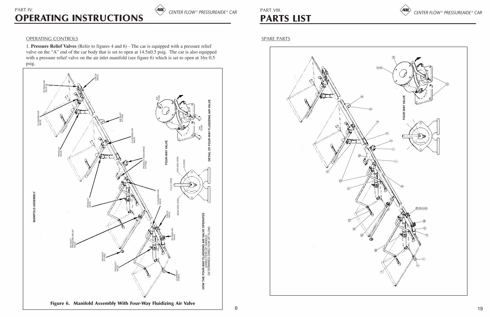
Figure 6. Manifold Assembly With Four-Way Fluidizing Air Valve
OPERATING CONTROLS
1. Pressure Relief Valves (Refer to figures 4 and 6) - The car is equipped with a pressure reliefvalve on the “A” end of the car body that is set to open at 14.5±0.5 psig. The car is also equippedwith a pressure relief valve on the air inlet manifold (see figure 6) which is set to open at 16± 0.5psig.
6
CENTER FLOW ® PRESSUREAIDE® CAR PART VIII.
PARTS LIST
FO
UR
-WA
Y V
ALV
E
7
16
15
14
1311
12
11
10
2
417
18
19
8
71
23
4
5
6
8
23
120 21 22
9
24
SPARE PARTS
19
CENTER FLOW ® PRESSUREAIDE® CAR

2. Rupture Disc - A rupture disc is applied tothe car body as a back-up safety device. Thedisc is designed to rupture at 20 psig at 72ºF andis located on the roof of the car.
3. Lading Controls - The product dischargeportion of the manifold is equipped with a prod-uct valve at each hopper. The air inlet portionof the manifold is equipped with a valvearrangement at each hopper to permit selectivefluidization of the hoppers and prevent the carfrom losing pressure if the blower inadvertentlyshuts down or if it’s necessary to disconnect theair inlet or product discharge hoses while the caris pressurized.
NOTE: BEFORE REMOVING ANY DUST CAP, OPEN THE BLOWDOWNVALVE, ANY FLUIDIZING VALVE ANDANY PRODUCT VALVE. IF GAUGE READINGS ARE NOT ZERO, CHECK
FOR FAULTY GAUGES.
4. By-pass Air Controls - A butterfly checkvalve arrangement is installed in the air supplyportion of the manifold at each end of the car.This permits air to be metered into the productdischarge line. The check valves are installed toprevent the back flow of lading if there is aninterruption in the air supply.
5. Blowdown Valve - A manually operatedblowdown valve is applied to the “A” end bulk-head to depressurize the car. This valve isequipped with a handle extension to permitoperation from ground level.
GENERAL UNLOADING INSTRUCTIONS
NOTE: BEFORE REMOVING ANY DUST CAP,OPEN THE BLOWDOWN VALVE, ANY
FLUIDIZING VALVE AND ANY PRODUCTVALVE. IF GAUGE READINGS ARE NOTZERO, CHECK FOR FAULTY GAUGES.
Prior to hook-up for unloading, inspect car thor-oughly to ensure:
1. All hatches are secure (See Figure 7).
2. Blowdown valve is in closed position (SeeFigure 8).
3. All product valves are closed.
4. All fluidizing air valves and by-pass airvalves are closed.
5. Pressure gauges are intact and petcocks areclosed. If petcocks are open, gauges will notgive accurate readings.
SAFETY LOCK
TYPICAL HATCH
BLOWDOWN VALVE
TO CLOSE
FABRICATED HANDLESPRING LOADED THROTTLE HANDLE
TO OPEN
Figure 7. Loading Hatches
Figure 8. Blowdown Valve
7
CENTER FLOW ® PRESSUREAIDE® CAR
CONDITION: NO LADING FLOW OR REDUCED FLOW (Cont.)
ACTION REQUIREDCHECK FOR
Plugged line. (continued)
Insufficient air flow or inadequate blower.
Rat holing (material hanging on side walls and outlet membrane covered).
Open product valve on the most empty hopper.
Restart blower.
Close product valve and allow the pressure in themanifold line to build to the maximum capacityof the blower or to a maximum of 14.5 psig.
Rapidly open and close product valve untilreverse flow starts. Leave valve open until flowstops. Close product valve and repeat.
When line pressure drops to a low pressure (lessthan 2 psig for most systems) with the productvalve closed, the line is clear.
When the plugged line has been cleared, closeproduct valve and open both by-pass valves toclear manifold.
Open fluidizing valve.
Close blowdown valve to re-pressurize car andproceed with unloading.
If the preceding procedures do not unplug theline, it will be necessary to disassemble theunloading line.
Open one fluidizing valve.
Open blowdown valve, depressurize car.
Open product valve on most empty compartment.
Close both by-pass air valves.
Shut off blower.
Manually disassemble and clean out product linebetween the car and the storage bin.
CAUTION - Be sure product line is depressur-ized before attempting to disassemble.
Check for proper size blower. Refer to guidelines on Page 5.
Check blower for proper operation. Consultblower manufacturer, if required.
Contact ARL representative.
The membrane may be plugged. Unload com-partment using manual assist if required. Contact an ARL representative. 18
CENTER FLOW ® PRESSUREAIDE® CAR

1. Remove dust cap and connect air supply lineto air inlet fitting. Air supply can be connectedto either side of the car (See Figure 9).
NOTE: CARE MUST BE EXERCISED TO ENSUREAIR SUPPLY LINE IS CLEAN AND FREE
OF CONTAMINATION.
2. Remove dust cap from product discharge lineon car and connect product line (See Figure 10).
3. Ensure all valves on the car are closed afterhook-up is completed.
4. Attach grounding straps to both the car bodyand the product discharge line.
PRESSURIZATION
1. Open fluidizing air valve to full open posi-tion on the first compartment to be unloaded.
2. Start the blower and pressurize the car.Monitor the pressure with the car’s pressuregauges (one gauge reads car body pressure, theother gauge reads air inlet pressure).
CAUTION: IF DUST EMITS FROM THE CAR,
IMMEDIATELY STOP UNLOADING.DEPRESSURIZE THE CAR, MAKE A THOROUGH INSPECTION AND
CORRECT THE PROBLEM. IF ANYCRACKS ARE FOUND IN THE CAR’S
STRUCTURE, CONTACT AN ARL REPRESENTATIVE. IF THE CAR’S BODY
PRESSURE EXCEEDS 15.0 PSIG AND THE PRESSURE RELIEF VALVE DOES NOT
OPEN, SHUT OFF THE AIR SUPPLY,BLEED PRESSURE FROM CAR AND
DETERMINE REASON FOR PRESSURERELIEF VALVE MALFUNCTION. IF A
MALFUNCTION OCCURS WHILE UNLOADING, REFER TO“TROUBLESHOOTING” SECTION ON PAGE 16.
3. When the car reaches the optimum operatingpressure, it is ready to unload. The maximumcar body operating pressure is 14.5 psig.Optimum pressures will vary depending uponthe unload site’s pneumatic unloading system.
FAR SIDE HOOK-UP
AIR INLET MANIFOLD
DUST CAP
CAMLOCK FITTING
AIR SUPPLY
CAMLOCK FITTING (ALTERNATE HOOK-UP)
PRODUCT DISCHARGE LINE
CAMLOCK FITTING
PRODUCT LINE
DUST CAP
PART IV.
OPERATING INSTRUCTIONS
HOOK-UP
Prior to removing any dust caps, open the blowdown valve, any fluidizing valve and any productvalve.
Figure 9. Air Inlet Manifold Figure 10. Product Discharge
8
CENTER FLOW ® PRESSUREAIDE® CAR
ACTION REQUIREDCHECK FOR
Leakage from car body.
Jammed check valve in air inlet portion of the manifold.
Contact an ARL representative.
Check valve is located in the air inlet portion ofthe manifold. Loosen bolts, inspect and reposi-tion.
CONDITION: CAR WILL NOT PRESSURIZE OR WILL NOT REACH OPERATING PRESSURE, (Cont.)
ACTION REQUIREDCHECK FOR
Jammed check valve or fluidizing air valve in airlines.
Excessive back pressure in receiving vessel.
Plugged line.
With blower running, rapidly open and closevalve.
Check to be sure fluidizing air valve is properlyinstalled. See Figure 6.
Remove valve and inspect for obstruction.Flapper must be free. If stuck, replace valve.
Check receiving vessel for proper air vent. Cleanair filters if applicable.
Immediately close all product valves and all fluidizing air valves. Open both by-pass airvalves to the full open position and restart blow-er, if shut off. If line can not be blown clear, (indicated by a line pressure drop) close by-passair valves and shut off blower.
CAUTION: If the blower must be shut downbefore line is clear, ensure the product valve onthe most empty compartment is open.
The following reverse flow procedure may alsobe followed to clear a plugged line:
1. Open blowdown valve to depressurize car.(Leave valve open).
2. Close all product valves.
3. Close all fluidizing air valves.
4. Open by-pass air valves to the full open position.
CONDITION: NO LADING FLOW OR REDUCED FLOW.
17
CENTER FLOW ® PRESSUREAIDE® CAR

UNLOADING
1. Open one by-pass valve to its full open posi-tion. Use the by-pass valve on the “A” end ofthe car for the “A” or “AC” compartment andthe by-pass valve on the “B” end of the car forthe “B” or “BC” compartment (See Figures 4 &6).
2. Open the product valve on the compartmentbeing fluidized.
3. In general, optimum unloading rates areobtained when the air inlet (manifold) pressuregauge reading is 1 to 3 psig higher than the carbody pressure gauge reading. Meter the productflow to suit the unloading system’s capacity andto avoid plugging the conveying line by adjust-ing the product valve and by-pass valve toobtain the best product-to-air mixture. Longconveying distances generally require more by-pass air than short conveying distances. Checkgauges to ensure proper pressures are beingmaintained.
4. If one side of the hopper is empty and theother side has material, use the four-way fluidiz-ing valve to direct air to the side that has materi-al in it.
5. A rapid drop in car body pressure normallyindicates the compartment is empty. Close theby-pass and product valves while continuing tosupply air. Open and close the product valve atabout twenty second intervals four or five timesfor final cleanout. Use by-pass air valve asneeded.
6. Open the fluidizing valve to the full openposition on the next compartment to beunloaded. Close all other valves on the car.
7. Allow car body pressure to build to operatingpressure.
8. Repeat steps 1 through 7 for each compart-ment.
9. After the last compartment is unloaded, openboth by-pass valves and close all other valves.Allow the blower to run a sufficient amount of
time to clean out the manifold and unloadingsite conveying lines.
10. SHUT DOWN THE BLOWER.
11. Open the blowdown valve on the “A” endof the car until all pressure is reduced to zeropsig and air has stopped flowing out of theblowdown valve. Disconnect flexible air andproduct hoses and secure all dust caps.
UNLOADING ASSISTS
1. Vibration - The unloading system for thePressureaide® car will provide satisfactorycleanout with most commodities. If unusualconditions exist which require vibration forcleanout, contact your ARL representative.
2. Fluidization - The Pressureaide® car isequipped with fluidizing membranes in eachcompartment. The air used for pressurizing thecar is adequate for fluidizing the lading and willprovide complete cleanout when the recom-mended unloading procedures are followed.
9
CENTER FLOW ® PRESSUREAIDE® CAR
ACTION REQUIREDCHECK FOR
Proper operation of gauges.
Dust cap installed.
Adequate air supply.
Obstruction or air leaks in air supply line.
Blown rupture disc.
Leaking blowdown valve.
Leaking or prematurely opening pressure reliefvalve.
Leaking vacuum relief valve.
Leaking hatch covers.
Open blowdown, by-pass or product valves, closedfluidizing valve.
Petcock on gauge line must be closed.
Check for clogged air line to gauge and clean ifnecessary.
Check pressure gauge calibration (consult gaugemanufacturer for instructions on calibratinggauges).
Check air inlet, cleanout port and product linedust caps to ensure they are installed with gasketsintact.
See Page 5 for air requirements.
Remove obstruction and repair leaks.
See Page 11 for rupture disc service procedures.
Close valve. If leakage persists, clean seat.
Refer to service and repair procedures for pres-sure relief valve Page 12.
With the car under pressure, depress vacuumrelief valve and release. Repeat 2-3 times. Ifthis doesn’t work, depressurize the car and cleanthe valve seat.
Check to be sure all hatches are closed and camlevers are secure.
Clean hatch cover gaskets and gasket seats.
Replace hatch gaskets and broken cam levers ifnecessary.
See Page 13 for hatch adjustments.
Close blowdown, by-pass and product valves. Open fluidizing valve.
CONDITION: CAR WILL NOT PRESSURIZE OR WILL NOT REACH OPERATING PRESSURE.
PART VII.
TROUBLESHOOTING
16
CENTER FLOW ® PRESSUREAIDE® CAR

PRESSURE GAUGES
(Refer to Figures 11 and 12)
Calibration of the pressure gauges should bechecked annually. To do this, install test gaugesto the fittings where the petcocks are located.Hook up the blower’s air supply line to the car’sair inlet. All valves, except one fluidizing valve,should be closed. With the fluidizing valve inthe full open position, pressurize the car to 10psig. If the car body or manifold gauge deviatesfrom the test gauge by more than one psig,return the gauge to American Railcar LeasingLLC.
If the pressure indicating needle does not moveafter the blower has been started, stop the blow-er and relieve the pressure in the car by openingthe blowdown valve. Disconnect the fittings atthe back of the gauges, the blowdown valve andthe air manifold. Attach a compressed air lineto the gauge line and blow the line clean.Reassemble and check gauges.
PART V.
GENERAL MAINTENANCE
Ensure there is no pressure on any portion of the car before attempting to perform any mainte-nance. Open the blowdown valve, any fluidizing valve and any product valve before removing anydust caps.
MANIFOLD PRESSURE
PROVISION FOR PADLOCK OR R. R. SEAL
TEST GAUGETEST
GAUGE
PETCOCKS
CAR PRESSURE
GAUGE BOXCOVER
CAR
BODY
MANIFOLD
PETCOCKS
PRESSUREGAUGEBOX
ATTACH COMPRESSEDAIR LINE HERE TOCLEAR LINE
Figure 11. Pressure Test GaugesFigure 12. Disconnected Tubing
From Gauges
10
CENTER FLOW ® PRESSUREAIDE® CAR
GENERAL CLEANING
1. Steam or grit blasting is not recommended aseither may cause damage to the lining or permeablemembrane. The most common methods of cleaninghopper cars are dry cleaning by scraping residue offwith plastic or wood scrapers and washing with water.
2. When entering the car, a ladder should be usedwhich is equipped with rubber or suitably padded feetto protect the permeable membrane. The laddershould not be allowed to rest on the membranes, norshould workmen walk on them. Of course, a ladderof adequate length should be used as well as follow-ing procedures compatible with good safety practices.
Scaffold brackets to assist in dry cleaning the car’sinterior can be provided if desired.
NOTE: RESIDUE FROM CLEANING WILL END UP INPRODUCT DISCHARGE MANIFOLD. THIS
RESIDUE CAN BE REMOVED THROUGH THECLEANOUT PORT PROVIDED IN THE DISCHARGE OUTLET CASTING OR BY
PRESSURIZING THE CAR AND OPENINGEACH PRODUCT VALVE INDIVIDUALLY.
CAUTION: IF THE CLEAN-OUT PORT HAS A FLANGED
COVER, REPLACE CLEAN-OUT PORT FLANGEAND GASKET AFTER CLEANING. (TORQUE
BOLTS TO 35 FT. LBS.)
WASH PROCEDURE
1. Connect a positive displacement blower with aminimum capacity of 450 CFM to the air inlet connection.
2. Close both by-pass air valves and all four fluidiz-ing air valves. Open all four product valves, removedust covers from each side of the product dischargeline and hook up hoses to direct air away from workstation. Open hatches on top of car.
3. Starting at one end of car, set the fluidizing airvalve to the full open position in the compartmentbeing washed.
4. Start blower.
5. Wash compartment by using a rotojet inserted into
the hatch opening or by a hand-held hose. AIRMUST CONTINUE TO BE BLOWN THROUGHMEMBRANE BEFORE, DURING AND AFTERWASHING.
NOTE: CARE MUST BE TAKEN NOT TO DIRECT A
HIGH PRESSURE STREAM OF WATER AT THEINLET PIPE OF THE RUPTURE DISC ASSEMBLY
LOCATED ON CAR’S ROOF. THIS COULDCAUSE DAMAGE TO THE DISC.
6. When compartment has been washed, allow air tobe blown through the membrane for an additional 10minutes, then open the fluidizing air valve on the nextcompartment to be washed. Close the fluidizing airvalve on the cleaned compartment.
7. Wash the remaining compartments following pre-ceding instructions.
8. When all compartments have been washed, openall four fluidizing air valves and allow air to blowthrough the membranes until interior of car is dry.
9. Shut off blower, close and secure hatches andclose all four product valves. Start blower and pres-surize car to at least 10 psig.
Starting at one end of the car, open the product valvefor approximately two minutes to blow water andresidue from the product line. Close the productvalve, pressurize the car and repeat for the remainingcompartments.
CAUTION: ENSURE HOSES ARE HOOKED UP TO BOTHPRODUCT DISCHARGE CONNECTIONS TODIRECT HIGH PRESSURE AIR AND RESIDUE
AWAY FROM WORK STATION.
10. With blower still operating, open both air by-passvalves and then all four product line valves. Blow fortwo minutes then shut off blower. Allow the car todepressurize. Remove the product line and clean outthe port cover. Inspect the discharge piping and thedischarge casting; wipe out any remaining residue.
11. Ensure pressure gauges read zero, disconnect airsupply line and replace all dust caps. Close by-passvalves and product line valves.
PART VI.
CLEANING
15
CENTER FLOW ® PRESSUREAIDE® CAR

VACUUM RELIEF VALVE
PROTECTIVE COVER
RUPTURE DISC
TOP OF CAR
"A" END BLOWDOWN VALVE
PRESSURE RELIEF VALVE
Figure 13. Safety Valves
Figure 14. Rupture Disc Assembly
RUPTURE DISC
(Reference Figure 13)
Inspect the rupture disc annually. If the seal isbroken, remove the protective cover and checkthe disc. Disc should be intact and in good con-dition. If condition is in doubt, pressurize thecar to 10 psig and inspect for leakage. If a leakis detected, depressurize the car and replace thedisc.
CAUTION: SUBSTITUTE OR MAKESHIFT DISCS ARENOT TO BE USED. SEE THE PARTS LIST
FOR SPECIFIED DISC.
DISASSEMBLY AND ASSEMBLY OF RUPTURE DISCS
(Reference Figure 14)
1. Remove protective cover (Item 1) by break-ing sealing wire and removing four nuts.
2. Inspect the rupture disc (Item 5) to determineif it has ruptured or if there are any imperfec-tions (tears, holes, etc.).
3. If disc must be replaced, remove flange (Item2) by removing four bolts and nuts (Item 3).
4. Foreign matter or rough surfaces may dam-age the rupture disc or cause leakage. Cleanseating surfaces of both inlet and outlet flanges(Items 2 & 4) before installing the rupture disc.Polish with a fine emery cloth.
5. When installing the rupture disc, handle care-fully. Examine seating and prebulged surfaces.DO NOT INSTALL A DAMAGED DISC!Damage to seating area may cause leakage.Damage to prebulged surface of disc may affectdisc rating. A vacuum support is permanentlyattached to concave side of disc. If missing ordamaged, replace the disc with a new one.
NOTE: DISCS ARE PACKAGED IN PROTECTIVE
CONTAINERS. DO NOT INSTALL SHIPPING PROTECTOR.
SEAL WIRE
1
SEATING SURFACE
RUPTURE DISC
3
4
52
1
11
CENTER FLOW ® PRESSUREAIDE® CAR
For Hatch Covers not using a retaining ring (SeeFigure 17):
1. Remove the worn gasket. This may be facil-itated by inserting a flat head screwdriver orknife blade along side of the straight outergroove wall and prying upward. When enoughgasket is exposed to grab onto, pull remaininggasket from its groove. Do not pry from ordamage the dovetailed inner groove wall.
2. Clean the gasket groove with a good solvent,such as methyl-ethyl ketone, to remove anyadhesive build-up. Wipe all surfaces of the newgasket with a clean, solvent-moistened rag toremove any dust or mold release agent that maybe present. Allow solvent to dry. Coat the bot-tom of the groove with a uniform, thin layer ofadhesive such as 3M’s Scotch-grip #1300Rubber Adhesive. Allow a couple of minutesfor adhesive to become tacky. Install new gas-ket, forcing it into the groove beginning at theinner groove wall at four points approximately90º apart. Continue forcing the gasket in thegroove using hand and thumb pressure until gas-ket is uniformly seated in its groove. A smallsteel wheel roller may help facilitate the laststep.
3. After the gasket is in place, be sure there isno excess adhesive exposed. Remove anyexcess with a clean, solvent-moistened rag. At this point the hatch cover should be reinstalledand/or cammed shut to ensure sufficient pres-sure for complete adhesive contact. Adjust per“Hatch Cover Installation and Adjustment”instructions.
DUST CAPS
Dust caps should be inspected prior to eachloading.
1. Open the blowdown valve, any fluidizingvalve and product valve before removing anydust cap.
2. Inspect for missing caps, broken or missingcam levers, gaskets and chains. Replace itemsas required.
INNERGROOVE WALL OUTER
GROOVE WALL
Figure 17. Hatch Cover Gasket
14
CENTER FLOW ® PRESSUREAIDE® CAR

6. Place rupture disc (Item 5) on inlet fitting(Item 4) with crown up. SYSTEM PRESSUREMUST BE AGAINST CONCAVE SIDE OFDISC.
7. Carefully place outlet flange (Item 2) in posi-tion. Install bolts and nuts and torque evenly to34 to 38 ft. lbs. Make sure flanges are notcocked. DO NOT OVER TORQUE! Angularseating surfaces help seal disc with minimumbolt loading. Excessive tightening may damagethe rupture disc.
8. Install protective cover and torque second setof nuts to 20 to 25 ft. lbs.
9. Install wire through holes in bolts and seal.
PRESSURE RELIEF VALVE
(Reference Figure 15)
Pressure relief valves should have a regular pro-gram of visual inspection. Build up of dirtand/or foreign material around and in the valveas well as broken parts will adversely affect thevalve’s operating characteristics.
The valves should be checked annually toensure they are opening at the specified pres-sures. This may be done with the valves installed on the car or they may be removed and
bench tested.
1. To remove valve, unscrew by placing a flatjawed wrench on flats provided. Do not use thevalve outlet or cap as a lever.
2. To reinstall the valve, apply a moderateamount of pipe compound to male threads only,leaving the first thread clean. Compoundapplied to female threads or used to excess canfind its way into the valve causing leakage.
NOTE: DO NOT OVERTIGHTEN.
3. The opening pressure for the relief valvemounted on the roof of the car is 14.5 psig. Theopening pressure for the valve on the air inletline is 16 psig. If the opening pressures vary bymore than ±0.5 psig, return the valve toAmerican Railcar Leasing LLC.
4. Do not paint, oil or otherwise cover any inte-rior or working parts of the pressure reliefvalves. These valves do not require any lubrica-tion or protective coating to work properly.
APPLY FLAT WRENCH THIS SURFACE
PRESSURE RELIEF VAVLE(SETTING 14.5 PSIG)
ROOF OF CAR
PRESSURE RELIEF VALVE(SETTING 16 PSIG)
AIR INLET MANIFOLD
LOOKING UP AT AIR INLET PIPING
Figure 15. Pressure Relief Valves
12
CENTER FLOW ® PRESSUREAIDE® CAR
HATCHES
(Reference figure 16)
Hatch covers, holddown assemblies, safetycatches and gaskets should be inspected prior toeach loading. Broken or missing parts shouldbe replaced and all cam levers properly adjust-ed.
HATCH COVER INSTALLATION
AND ADJUSTMENT
Use this procedure to adjust existing hatch cov-ers and for installing new hatch covers.
1. With all cam levers disengaged, center hatchcover on hatch ring. Ensure the hatch hinge pinis installed. This will center the cover along thecenterline of the car, then it can be moved to theright or left to center it across the car.
2. Loosen set screw in the cam lever assembliesand adjust and engage the two cam levers locat-ed 90º from the hinge (some cam lever assem-blies are not equipped with set screws). Bothlevers must be adjusted at the same time.(Rotate entire cam lever assembly clockwise totighten and counter-clockwise to loosen).Levers should be adjusted so that each requiresabout 40 lbs. of force to lock down.
3. Adjust remaining cam levers (levers acrossfrom each other should be adjusted simultane-ously). All levers should require approximately40 lbs. of force to engage.
4. Recheck all cam lever forces (some of thelevers might require additional adjustment dueto the gasket compression).
5. Retighten all set screws.
HATCH GASKET REPLACEMENT
There are two gasket designs in service. Ensureyou identify the proper arrangement beforeordering gaskets for a hatch cover.
For Hatch Covers using a retaining ring seeFigure 16):
1. Remove cap screws and shakeproof washers(Items 1 and 2).
2. Remove gasket retainer (Item 4) and old gas-ket (Item 3).
3. Thoroughly clean gasket retainer and seal onhatch cover and hatch ring.
4. Install new gasket and reassemble.
5. Adjust per Hatch Cover Installation andAdjustment instructions.
CENTERLINE
OF CAR
SAFETY CATCH
HATCH HINGE PIN
TYPICAL HATCH
ADJUST THESELEVERS FIRST
CAM LEVER
5/16"*SET SCREW
(Optional) CCW
CW
COUNTER-CLOCKWISE (LOOSEN)
CLOCKWISE (TIGHTEN)
HATCH ADJUSTMENT*REQUIRES A 5/32"ALLEN WRENCH
3 4 1 2
Figure 16. Hatches
13
CENTER FLOW ® PRESSUREAIDE® CAR