Embed Size (px)
Citation preview

Cellwatch Battery Monitoring System SYSTEM INSTALLATION & USER MANUAL Version 5.2.9

Part No 615003-V5.2.9-3 Nov 2015

Contents
1. Hardware & Installation Manual
2. Software Manual
3. User Training Manual
4. Application Notes

Installation Information This page should be completed upon installation of the Cellwatch system for future reference: Date Site Commissioned: _________________________________________ System Installed by (Company): ____________________________________ Installer’s Certification Expiration Date: ______________________________ System Installed by (Installer): _____________________________________ Contact Phone Number: _________________________________________ All technical assistance with your product can be obtained through a Certified Installer for the Cellwatch system. Please contact the company above for assistance with Cellwatch.
NDSL, manufacturers of Cellwatch, can be contacted by visiting: http://www.cellwatch.com/contact

Installation Manual
TABLE OF CONTENTS
Trademarks ............................................................................................................................. 9 Copyright ................................................................................................................................ 9 Life Support ............................................................................................................................ 9 Liability .................................................................................................................................... 9 Specification ........................................................................................................................... 9 Warranty ................................................................................................................................. 9 Limitation of Warranty ............................................................................................................. 9 .Safety .................................................................................................................................... 9 Tools and Equipment .............................................................................................................12 Cellwatch™ Service and Support ...........................................................................................12
INSTALLATION: INTRODUCTION .............................................................................................13 System Overview ...................................................................................................................13 System Requirements ............................................................................................................14
INSTALLATION: CELLWATCH SYSTEM COMPONENTS .........................................................16 The iBMU (Integrated Battery Monitoring Unit) .......................................................................16 The Control Unit .....................................................................................................................18 Cellwatch Control Unit Specification .......................................................................................19 Data Collection Modules (DCMs) ...........................................................................................21 Regulatory Compliances ........................................................................................................23
INSTALLATION: OVERVIEW .....................................................................................................24 Installation Check Lists ..........................................................................................................24 Critical Distances ...................................................................................................................26 Physical Mounting and Location - General .............................................................................27 CU Cabinet Mounting Overview .............................................................................................27 Cabinet Mounting Instructions - General ................................................................................28 Masonry wall. .........................................................................................................................28 Sheet steel fixing. ...................................................................................................................28
INSTALLATION: CELLWATCH IBMU ........................................................................................29 Rack Mounting .......................................................................................................................29 Wall Mounting ........................................................................................................................29 Wall Kit Mounting Instructions ................................................................................................30 Prepare the iBMU Chassis. ....................................................................................................30 Connecting RS-485 to the IBMU ............................................................................................30 Connecting an IBMU to a Corporate Network ........................................................................31 Network Security ....................................................................................................................31 Settings ..................................................................................................................................32 Remote access ......................................................................................................................32 Other features ........................................................................................................................33 Password summary................................................................................................................33 Connecting to an iBMU ..........................................................................................................33 Powering an iBMU .................................................................................................................33 Installation: The Control Unit (CU) or Thermal Runaway Controller ........................................34 Thermal Runaway Controller Inputs and Outputs (this represent the Control Unit Inputs and Outputs as well) .....................................................................................................................34 Physical mounting of Control Units. ........................................................................................36 Power Inputs ..........................................................................................................................36 Low Voltage Inputs/Outputs ...................................................................................................37
Isolated Relay connectors. .....................................................................................................37 Relay Assignments ................................................................................................................39 Step Up Circuit for Applications Requiring > 30 V, 5 A DC .....................................................41 Current Probe Connectors. ....................................................................................................42 Temperature probe connectors ..............................................................................................42 Auxiliary Power Take Off Connector ......................................................................................42 Control Unit RS-485 connectors .............................................................................................42 Multiple Control Units .............................................................................................................44 Control Unit, Thermal Runaway Controllers and Genset Addresses ......................................44 Setting Primary and Genset Addresses .................................................................................44 RS-485 Bus termination. ........................................................................................................45 Fiber Optic Link ......................................................................................................................45
INSTALLATION: THE DCMS ......................................................................................................46 Simple rules ...........................................................................................................................46 Preparing the battery..............................................................................................................46 Tabbing the Battery ................................................................................................................46 Type 1 Installation onto trays in a Battery Cabinet. ................................................................51 Type 2 & 3, VRLA on shelves in a cabinet or on open racks ..................................................53 Type 4 & 5, Low Ohmic Value wet cells on a rack and VRLA or AGM front connected jars. ...56 Considerations for cells with 4 or more posts .........................................................................57 Other Considerations .............................................................................................................58 Connecting the DCMs ............................................................................................................61 DCM Location. .......................................................................................................................61 DCM Connection Order ..........................................................................................................63
INSTALLATION: CURRENT TRANSDUCER LOCATION AND ORIENTATION .........................64 Position ..................................................................................................................................64 Filter Box ................................................................................................................................64 Cable Routing ........................................................................................................................64 Orientation .............................................................................................................................65 Connecting the CT to the Control Unit. ...................................................................................66 Cable and Connector. ............................................................................................................66 Extending cable Length. .........................................................................................................66 Zeroing CTs ...........................................................................................................................67 Scaling CTs ...........................................................................................................................67
INSTALLATION: CABLE TYPES AND RATINGS. ......................................................................68 Control Unit. ...........................................................................................................................68 Power input cables recommendations ....................................................................................68 Conduit ..................................................................................................................................69 Weights ..................................................................................................................................69 Cable Types ...........................................................................................................................69 RS-485 cable .........................................................................................................................69 Current clamp cable type .......................................................................................................70 Temperature probe cable type ...............................................................................................70 Alarm Relay cables ................................................................................................................70 Cleaning. ................................................................................................................................70 Commissioning ......................................................................................................................70 User Training .........................................................................................................................70
INSTALLATION: START UP .......................................................................................................71 Remote Desktop ....................................................................................................................71
INSTALLATION: INITIAL SETUP ...............................................................................................72 Factory Software Settings ......................................................................................................72

What You Will Also Need .......................................................................................................72 The procedure........................................................................................................................74 How to recognize a Cross-Over cable. ...................................................................................74 Set-Up procedure ...................................................................................................................75 Localizing iBMU Settings .......................................................................................................76 (Legacy) Using a Modem Connection and PCAnywhere ........................................................76
INITIAL CELLWATCH CONFIGURATION ..................................................................................77 Default Configuration File .......................................................................................................78 Creating A Custom Configuration File ....................................................................................79
INSTALLATION: CONFIGURATION BUILDER ..........................................................................80 The Need and the Function. ...................................................................................................80 Glossary of Terms ..................................................................................................................81 Running the Program .............................................................................................................82 Operating the software ...........................................................................................................82 Configuration Wizard..............................................................................................................83 Substrings in the Wizard ........................................................................................................86 Configuration Builder (i.e. non wizard mode) ..........................................................................86 Drop Down Menus .................................................................................................................86 Tool Bar .................................................................................................................................87 More Options .........................................................................................................................89 Split strings, short strings and nulls ........................................................................................90 Split-Strings ...........................................................................................................................91 Short Strings and Null Channels ............................................................................................91 Short Tray Solutions...............................................................................................................92 Review Screen .......................................................................................................................94 Edit ........................................................................................................................................94 Save ......................................................................................................................................95 Errors .....................................................................................................................................95
INSTALLATION: TROUBLESHOOTING AN INSTALLED SYSTEM ...........................................96 Final Check List .....................................................................................................................96 Running Cellwatch Software for the First Time. ......................................................................96 Common Faults ......................................................................................................................97 Temperature Probes are Incorrect .........................................................................................97 Current Readings are Positive in a Discharge File .................................................................97 Navigating Diagnostics ...........................................................................................................98 Error: No Loop Back ..............................................................................................................98 A faulty DCM Loop .................................................................................................................99 How to Verify a DCM............................................................................................................ 100 What happens if there are crossed wires from a DCM ......................................................... 100 RS-485 Troubleshooting ...................................................................................................... 103 Troubleshooting with Multiple Control Units and Thermal Runaway Controllers ................... 103 Fault Finding Flow Chart ...................................................................................................... 105
FINAL POST TROUBLESHOOTING CHECKLIST ................................................................... 106 TIP - Continuous Buzzer. ..................................................................................................... 106 Installation: Maintenance ..................................................................................................... 107 Battery Storage, Care and Maintenance .............................................................................. 107 Design Life ........................................................................................................................... 107 Battery Care ......................................................................................................................... 108 Battery Safety ...................................................................................................................... 108
INSTALLATION: ABBREVIATIONS AND DEFINITIONS .......................................................... 109
SOFTWARE: INTRODUCTION ................................................................................................ 113

Contact your Cellwatch supplier: .......................................................................................... 113
SOFTWARE: OVERVIEW ........................................................................................................ 114 What this software will do for you ......................................................................................... 114 What Cellwatch monitors ..................................................................................................... 114 How often ............................................................................................................................. 114 What output files it generates ............................................................................................... 114 What should I do with the data? ........................................................................................... 115 Who to contact for Additional Assistance? ........................................................................... 115
SOFTWARE: USING THE SOFTWARE ................................................................................... 116 Introduction to using Windows applications. ...................................................................... 116 The Controls, basic description (for users new to Windows). ............................................ 117 The Drop Down Menus, Basics. ........................................................................................... 117 The Drop Down Menus, in Depth. ........................................................................................ 118 Graphical User Interface (GUI) ............................................................................................. 126 Activity indicator ................................................................................................................... 126 Information Contained in the Battery Panel .......................................................................... 129 The Cell Depictions. ............................................................................................................. 129 Shortcuts Summary ............................................................................................................. 131
SOFTWARE: GRAPHICAL DISPLAYS..................................................................................... 135 The Cell Voltage & Ohmic Value Graph Window. ................................................................. 135 The Drop Down Menus. ....................................................................................................... 136 Graph Data Source Tabs. .................................................................................................... 137 The Information Area ........................................................................................................... 137 The String Voltage and Ohmic value Window ...................................................................... 138 Description ........................................................................................................................... 138 The History Window ............................................................................................................. 139 The Drop Down Menus. ....................................................................................................... 139 Graph Radio Buttons............................................................................................................ 140 The Information Area ........................................................................................................... 140 Dual Axis Plotting ................................................................................................................. 142 Alarm Level Displayed on History Graph .............................................................................. 143 The Discharge File ............................................................................................................... 145 The Drop Down Menus ........................................................................................................ 146 The Information Area ........................................................................................................... 147 Voltage Alarms during a Discharge ...................................................................................... 148
SOFTWARE: THE DATA OUTPUT FILES ............................................................................... 150 The Configuration Files ........................................................................................................ 150 The Discharge File ............................................................................................................... 150 The Recharge File ............................................................................................................... 150 The History File. ................................................................................................................... 150 The Log File ......................................................................................................................... 151 Opening data in Excel or other Third Party Applications ....................................................... 151
SOFTWARE: DATA MANAGER ............................................................................................... 152 Main grid .............................................................................................................................. 152 The filter control panel .......................................................................................................... 153 Filtering by date ................................................................................................................... 153 Filtering by alarm type .......................................................................................................... 153 Filtering by active and acknowledged status ........................................................................ 154 Acknowledged / unacknowledged alarms ............................................................................. 154 Active alarms ....................................................................................................................... 154 Inactive Alarms .................................................................................................................... 154

Filtering by battery, string and cell ........................................................................................ 155 Refreshing to view new alarms ............................................................................................ 155 Exporting Data to a CSV Format File ................................................................................... 156 Backup and/or Clear Database ............................................................................................ 156
SOFTWARE: I WANT TO… ..................................................................................................... 157 … Stop the Initial Ohmic value Scan. ................................................................................... 157 … Run the Monitoring System Once and Look at the Data. ................................................. 157 … Change the Configuration ................................................................................................ 157 … Review the Data from the System across a network. ....................................................... 159 … Receive Ohmic Value alarm notifications later in the working day (i.e. Delay the Ohmic Value scan)… ...................................................................................................................... 159 … Back-up my data ............................................................................................................. 159
SOFTWARE: OPERATION AND SET-UP OF ALARM FUNCTIONS ....................................... 161 Introduction .......................................................................................................................... 161 Alarm Indication Philosophy and Implementation in Cellwatch™ ......................................... 161 Setting the Alarm Levels. ..................................................................................................... 162 Temperature ........................................................................................................................ 162 Current ................................................................................................................................. 162 Voltage................................................................................................................................. 163 Ohmic Value ........................................................................................................................ 165 Thermal Runaway ................................................................................................................ 176
SOFTWARE: COMMUNICATION ............................................................................................. 181 Building Management System (BMS) Interface .................................................................... 181 MODBUS TCP/IP Interface .................................................................................................. 182 Converting Modbus TCP/IP to BacNET, DNP3, or other interfaces ...................................... 182 Polling Rates ........................................................................................................................ 182 Browser Interface ................................................................................................................. 183 Turning Web Browsing On. .................................................................................................. 183 The Pages ........................................................................................................................... 183 System Page. ...................................................................................................................... 184 Battery Page ........................................................................................................................ 185 String Page .......................................................................................................................... 186 Logs, discharges and history files. ....................................................................................... 187
SOFTWARE: QUICK REFERENCE ......................................................................................... 188 License Auto-Activation ........................................................................................................ 188 License Activation Required: Extended Feature Sets ........................................................... 188 The iBMU ............................................................................................................................. 188 Restoring Cellwatch Data ..................................................................................................... 189 Restoring a Lost Configuration File ...................................................................................... 189 Restoring a Batconfig.cfg from a History (.his) or Discharge (.dis) file .................................. 189 Hardware Detect (H/W Detect) ............................................................................................. 189 Configuration File headings. ................................................................................................. 189 Scaling Current Clamps ....................................................................................................... 191 Single String Current ............................................................................................................ 193 The .ini File .......................................................................................................................... 195 Defaults................................................................................................................................ 195
SOFTWARE: TROUBLESHOOTING & MAINTENANCE .......................................................... 199 Fiber retesting ...................................................................................................................... 199 Password persistence .......................................................................................................... 199 Exiting the Program ............................................................................................................. 199
USER MANUAL ........................................................................................................................ 201

USER MANUAL: INTRODUCTION ........................................................................................... 202 Important Note on Power Failures and Turning OFF an iBMU ............................................. 202
USER MANUAL: VALIDATE THE SYSTEM ............................................................................. 203 Is it working? ........................................................................................................................ 203 Indications that Cellwatch is not running… ........................................................................... 203 Is it installed & configured correctly? .................................................................................... 204 Are the alarms set up correctly? ........................................................................................... 204 Are the cells Green or Red (i.e. in alarm)? ........................................................................... 205
USER MANUAL: WHAT TO LOOK FOR .................................................................................. 207 The daily or weekly check .................................................................................................... 207 Alarm Conditions – Red Tabs, Cells, or Data Manager Events ............................................ 207 Post discharge event check ................................................................................................. 209 Periodic review..................................................................................................................... 210
USER MANUAL: OTHER FUNCTIONS AND TASKS ............................................................... 211 Other Useful Tools ............................................................................................................... 211 File Viewer ........................................................................................................................... 211 Email Notifications ............................................................................................................... 211 SNMP Agent ........................................................................................................................ 211 Exporting the data to Microsoft® Excel or CSV .................................................................... 211 Capture the present day’s reading taken and store it in Excel. ............................................. 212 Convert the History file into a CSV for Excel or other programs ........................................... 212 Discharge data ..................................................................................................................... 213 What to do if changing out a jar or cell ................................................................................. 214 IMPORTANT SAFETY WARNING ....................................................................................... 214 Removal and Refitting of a DCM .......................................................................................... 215 Adding more hardware (strings or batteries) ........................................................................ 216 When you first start Cellwatch .............................................................................................. 216 How to do it right. ................................................................................................................. 216

9
TRADEMARKS
All brand and product names are the trademarks of their respective owners. Cellwatch™ is the registered trademark of NDSL Group Limited in the UK and the USA and a trademark of NDSL Group Ltd. in the rest of the world.
COPYRIGHT
© All rights reserved. No part of this manual shall be stored in a retrieval system, or transmitted by any means, electronic, mechanical, photocopying, recording or otherwise without the written permission of NDSL Group Limited.
LIFE SUPPORT
NDSL products cannot ensure performance for life-support devices or systems since the end user is responsible for monitoring and management of the system.
LIABILITY
Neither NDSL nor any of its employees shall be liable for any direct, indirect, incidental or consequential damages arising from the failure of the battery monitoring system due to the failure of a proprietary part of the battery monitoring system, even if NDSL had been advised in advance except for as provided by law.
SPECIFICATION
NDSL makes every effort to ensure that the specifications and details in this manual are accurate and complete. NDSL reserve the right to alter or improve the specification, design or manufacturing process at any time, without notice.
WARRANTY
Please contact your Cellwatch installer/provider for warranty issues.
LIMITATION OF WARRANTY
This warranty does not apply to defects arising from system modification performed without NDSL’s written approval, or misuse of the system or any part of the system. The warranty excludes defects or malfunctions resulting from failure by the customer, or his designated personnel, to maintain and upkeep the batteries to which the system is fitted
This warranty does not apply to any part of the system supplied by the customer or problems arising from normal wear and tear or failure to follow instructions.
.

10 V 5.2.9 - November 2015

11
SAFETY
The following safety precautions should be observed before any work is performed on the system containing the NDSL product.
This system is intended for installation by personnel who are trained and qualified to recognize the hazards associated working with such systems and are familiar with the safety precautions required to avoid possible injury.
Never work on any system that threatens life or injury through hazardous voltages. Even when safety precautions have been taken.
NEVER WORK ALONE. Always ensure that two properly trained personnel are on site.
NDSL recommends that when performing any work concerned with batteries, that the safety procedures and safe working practices as described in the appropriate battery manufacturers documentation should be followed at all times.
Never make unauthorized changes or modifications to equipment. This may create unsafe or even hazardous situations.
Where the battery documentation recommends that links are removed for safe working, it is important to totally remove any Cellwatch unit which is connected across any link to be broken prior to separation and subsequent removal of the link. FAILURE TO DO SO WILL RESULT IN THE STRING NOT BEING TOTALLY ISOLATED.
After servicing of the battery, any removed links must be fitted and reconnected before the Cellwatch™ modules are reconnected.
NOTE. The Control Unit, Thermal Runaway Controller, and the Integrated Battery Monitoring Unit contain high voltage parts. Only trained and qualified personnel should open the Control Unit, Thermal Runaway Controller, or the Integrated Battery Monitoring Unit.
The battery monitoring system including the Control Unit, Thermal Runaway Controller, and the Integrated Battery Monitoring Unit should be powered from a properly grounded/earthed AC supply and be backed up by UPS power.

12 V 5.2.9 - November 2015
TOOLS AND EQUIPMENT
Safety glasses should be worn at all times.
Ensure all equipment and tools are safe and in good working order.
Ensure electrical tools have been tested for proper insulation and grounding where appropriate.
Do not wear loose clothing, jewelry, long hair when working near rotating machinery.
Appropriate PPE should be utilized depending upon the application and hazards present.
Observe all CAUTIONS, WARNINGS and DANGER notices on equipment, tools, and buildings whether internally or externally displayed.
CELLWATCH™ SERVICE AND SUPPORT
If during the use of the NDSL product any cracks, breaks or defects are found in any of the units then please contact NDSL. You will be advised on the necessary action to be taken.
Visit http://www.cellwatch.com for the latest contact information and locations
NOTE: This manual does not have an update service. This manual is also supplemented by application notes. Up-to-date copies of the manual and application notes can be obtained by contacting your
dealer, NDSL, or visit the application notes web site:
www.cellwatch.com/AppNotes
Danger Live Electrical Equipment Danger Du Matériel Électrique
13
INSTALLATION: INTRODUCTION
The concepts behind the Cellwatch system are flexibility, ease of installation, safe use and operation. It can be installed on a new or old battery. The modular design allows the system to fit applications of any size and configuration including monitoring several separate battery systems simultaneously. Battery parameters which can be monitored on per cell, per jar, or mono-bloc basis include:
On Float Voltage
Ohmic Value
On a battery system it can report on
Total String/Battery Float Voltage
Individual Jar/Cell Float Voltage
Discharge Voltage per Jar/Cell
String Current
Ambient Temperature
Pilot Temperature
Per Cell Temperature
Ripple Voltage
Thermal Runaway Conditions
Dependent upon Current, String Temperature and Jar Voltage
SYSTEM OVERVIEW
The system is built using modules. The majority of the system is constructed with Data Collection Modules (DCMs). The DCMs are optically linked to Control Units (CUs) or Thermal Runaway Controllers (TRCs) that in turn are connected via RS-485 to the Integrated Battery Monitoring Unit (iBMU), a central cabinet or wall mounted server, running proprietary Cellwatch software
under the Windows Embedded operating system.
The system architecture is such that the battery monitoring system can easily be configured for any size battery, anywhere and can be economically expanded. Components are also designed to have a useful life beyond that of the battery and could be used on a new battery following decommissioning of a retired battery.
The diagram in figure 1 shows a basic layout of the Cellwatch system. Each DCM can read voltage or Ohmic Value data from four monitoring points, typically either a module or container that contain one or more cells. The controller provides the ability to monitor string current and temperature as well as converts fiber optic communications into RS-485 for communication to the IBMU. The TRC includes the functions of a control unit with the addition of relays that can be utilized to remove a string from service if thermal runaway conditions are present. All DCMs are linked fiber optically in a series loop to the controller keeping each module electrically isolated from each other.

14 V 5.2.9 - November 2015
Figure 1
One iBMU can control any combination of Control Units (CUs) or Thermal Runaway Controllers (TRCs) up to 31 unit addresses. Each CU or TRC can control up to 254 Data Collection Modules (DCMs) and can connect to remote generator batteries, monitoring up to 254 DCMs. Each CU has 4 current inputs and 4 temperature inputs, 4 alarm triggered volt free relay contacts, and a generator extension remote. Each TRC has up to 4 current inputs, up to 4 temperature inputs, 10 alarm triggered volt free relay contacts, and a generator extension remote controller.
NOTE: While the IBMU is fully capable of monitoring several thousand jars, for best performance it is recommended that no more than 1000 jars, or 250 DCMs be connected to any IBMU at a given time. Data capture scan speeds will degrade when exceeding 1000 monitoring points.
SYSTEM REQUIREMENTS
The Cellwatch system’s DCMs are semi-permanently connected to the cells, jars or monoblocs of the battery system to be monitored. Battery types, which can be monitored, include:
Valve Regulated Lead Acid, 200 micro ohm to 25.9 milli ohm
Lead Acid (flooded), 5 micro ohm to 65 milli ohm
Ni-CAD, 50 micro-ohm to 20 milli-ohm.
Straps 1micro ohm to hundreds of micro ohms
Permanent physical connection to the battery system is required in all cases.

15

16 V 5.2.9 - November 2015
INSTALLATION: CELLWATCH SYSTEM COMPONENTS
THE IBMU (INTEGRATED BATTERY MONITORING UNIT)
The purpose of the iBMU is to control all aspects of the monitoring process including: retrieving, displaying and saving data; indicating alarm activation; processing data for historical trending; real time calculations; and control outputs to trigger external functions.
The Battery Monitoring Unit server forms the heart of the Cellwatch system with a minimum specification of the following:
8GB HDD storage
USB connection for data retrieval
1 non-transferrable activated license for Cellwatch
Windows 7 Embedded OS with automatic updates disabled
Environmental
Operating Temperature 0 – 40 ºC
Humidity 5 – 95% non-condensing
The iBMU must be powered from a UPS backed primary supply of 110 or 240 v AC at either 50 or 60 Hz. The system comes in a 2U high 19” rack-mount case, which can be connected to rails for a rack solution (universal rail kit available, sold separately) or wall mounted (sold separately) to be installed in the battery room.
The data is presented on an optionally connected color screen or over an Ethernet network connection using Remote Desktop, or with a third party appliance such as a KVM over IP. A KVM over IP option allows the iBMU to be accessible via the network but isolated from the network as the KVM connects directly to the monitor, keyboard, and mouse ports on the iBMU.
Cable entry into and out of the iBMU case is via industry standard connections in the back of the case.
Languages
Cellwatch software is available in English, French, Chinese, Korean, and Japanese languages. The IBMU can be configured to run Windows in these default languages as well.
Optional Keyboard Interface Type (not supplied)
Standard PC USB keyboard and mouse.
Optionally KVM or KVM over IP devices may be used.
Ports 1 serial communication port RS-232 1 serial communication port RS-485 4 USB ports 2 Network Interface Connector (NIC) 10/100/1000 MHz Ethernet connection One static service port (192.168.0.128/255.255.255.0)
One dynamic (DHCP enabled) 1 VGA video port 1 DVI video port

17
The Cellwatch Software
The Windows Operating System is custom configured to reduce security risks and produce a stable and standardized platform.
An Administrative user (Cellwatch) is created and this is configured to auto-logon to the system on boot up. This user should NOT be changed and will void warranty if the password, administrator privileges, or user name is changed. This configuration on the IBMU ensures that Cellwatch will properly power on, boot into Windows, and begin monitoring cells should power fail on the IBMU without any instruction from a user.
The Cellwatch Suite consists of:-
1. The Cellwatch executable (i.e. Cellwatch.exe) that monitors the status of the monitored batteries.
2. The Configuration builder, used by the installer to build a configuration file describing the battery system.
3. The Application Server, a database used by Cellwatch to maintain a record of alarm and event notifications.
4. The Data Manager, used by the end-user to review records in the Application Server.
5. An Email Alert program that sends out Emails to pre-programmed addresses in the event of alarms. This software is free for Cellwatch 4 users and must be registered to activate.
The Cellwatch software is designed in a modular way to allow for a flexible solution with easily defined setup and configuration, making a very “user friendly” system.
On startup, once all parameters are known the program then performs an initialization followed by a scan of all battery components. The data is updated after each DCM reading and the graphical display updates according to the alarm condition of the jar, battery, or string. Updates can be tailored to suit the installation or customer requirements.
All retrieved data is stored as either Configuration (.cfg, .xcfg), Discharge (.dis), History (.his), or Comma Separated Variable files (.csv) and may be displayed as a spreadsheet in most formats (e.g. Microsoft Excel). All files except the .xcfg can be modified to a CSV file for easy viewing. Data sets include:-
1. Float voltage and ohmic value scans for each block or jar during a day
2. Float voltage, ohmic value, current and temperature averages for each day available in the history file.
3. Voltage data for each block or jar every few seconds on any battery on discharge.
4. A log file for every day of operation detailing all events, recorded chronologically.
5. User selectable reports for voltage, ohmic value, temperature, current, thermal runaway, and string voltage alarm history.
6. Alarms can be captured and displayed by viewing the configuration file.
For a full and comprehensive description of the Cellwatch software, please refer to the Software section covered later in this Handbook.

18 V 5.2.9 - November 2015
THE CONTROL UNIT
Control
Unit 1
(CU)
iBMU
UPS System 40 Jar Battery Cab. 40 Jar Battery Cab.
DCM
DCM
DCM
DCM
DCM
DCM
DCM
DCM
DCM
DCM
DCM
DCM
DCM
DCM
DCM
DCM
DCM
DCM
DCM
DCM
To additional CU or TRC modulesRS-485 Data Connection
Fiber Optic
Communications
Figure 2, Control Unit and Partial System
The Controller communicates to the DCMs via a fiber optic loop. The functions of the Controller include; conversion between digital RS-485 and optical signals, up to four independent current readings per Control Unit, up to four independent temperature reading per Control Unit for ambient and/or pilot cell temperatures and the facility for four volt free contacts to be used as alarm and control outputs. A total of 31 RS-485 Addresses can be connected to a single IBMU.

19
Cellwatch Control Unit Specification
Operating specifications:-
Ambient operating temperature Voltage readings 0ºC to 50ºC Storage temperature:- -10C to 80C
Maximum Relative Humidity: 95% non-condensing
Maximum Altitude: 2,000 meters (6,000ft)
Pollution category:- Dry and non-conductive pollution with temporary conductivity due to condensation.
Power supply:-
Permitted mains supply variations
Required to be fed from UPS.
110 to 240 VAC
+/-10%
Transient over-voltage category: Category II
Power supply Frequency 50 Hz to 60 Hz
Power supply power rating 20 Watts
Fuse rating 240 volt 250 mA Slo Blo
Communications:-
RS-485 interface Input and output with optional jumper for bus termination. Signal not regenerated
Max range 2,000ft (600meters) total bus length.
Fiber optic range (can be extended with Fiber Optic extender Kit)
Min 150mm (6”)
Max 45meters (150 ft) (No radius sharper than 130mm (5”))
Maximum CUs per RS-485 bus: 31
Cable Type Belden 8102 or equivalent
Interface for generator extension kit RJ45
Alarm Outputs:-
Output Relays 5 relays, each single contact, volts free change over. 10 relays for Thermal Runaway Controller
Electrical characteristics 30 VDC @ 5 amps max.
Electrical isolation: 1500 VAC
Sensing inputs:-
Temperature sensor Solid state probe
Resolution 0.05 degrees C
Accuracy +/- 1 degrees C
Range 2 to 80 degrees C

20 V 5.2.9 - November 2015
Mounting 8mm (5/16”) lug fitted to adhesive pad (removable)
Current Sensor Solid state, magnetic core sprung clamp. 2” (50mm) capacity (1,000 amp) or 4.5” (112mm) 2,500 amp.
Resolution 0.5 amp
Useful range +/- 10 to maximum amps of clamp
Communication rate:- 9600 baud
Maximum Cable distance:- 150 feet (45 meters)
Protection:-
Sensing Inputs Short circuit proof
Insulation resistance 600 volts DC
Physical Characteristics:-
Dimensions 302mm x 298mm x 121mm (11 7/8” x 11 ¾” x 4 ¾”)
Mounting centers 4 corner mounting holes, 260mmx 260mm (10 7/32” x 10 7/32”) centers.
Mounting hole size 8mm (5/16”) diameter.

21
DATA COLLECTION MODULES (DCMS)
Data collection modules are voltage and Ohmic Value (O.V.) measurement instruments that can measure the voltage and O.V. of up to four measurement points to which they are connected.
They are designed to be connected in a serial data loop. This loop utilizes fiber optic cable for reliability and safety. Each DCM has a transmitter (white or blue connector) and a receiver (black connector) that is fiber cabled to the next DCM and continues until a loop is formed returning to the Controller.
Seven cables are used for connection to four measurement points on a battery. These points can be cells (2V minimum) or blocks or jars, say 6V, 8V, 12V, or 16V. Alternatively they can be used to measure multiple blocs or jars or even inter-cell links. NOTE the max rating of any DCM is 80V DC.
Additional information can be found for connecting to 16v jars on the application notes website (http://www.cellwatch.com/appnotes). For 16v configurations each DCM should be connected to no more than three jars. Caution should be used when connecting to jars or containers greater than 12V as voltages in excess of 80 V would be reached when monitoring more than three 16 v jars.
Connection to the battery is made using ¼ inch fast-on terminals to tab washers supplied as part of the system. These tab washers are fitted directly to the battery posts or on to the inter cell straps. For a visualization of the connection of a DCM to a battery see the diagram below. Tab washer sizes vary from M5 (1/5 in.) to M12 (1/2 in.).
Additional information about connecting a DCM to a battery and various configurations are found later the manual.
Figure 3, DCM connection.
22 V 5.2.9 - November 2015
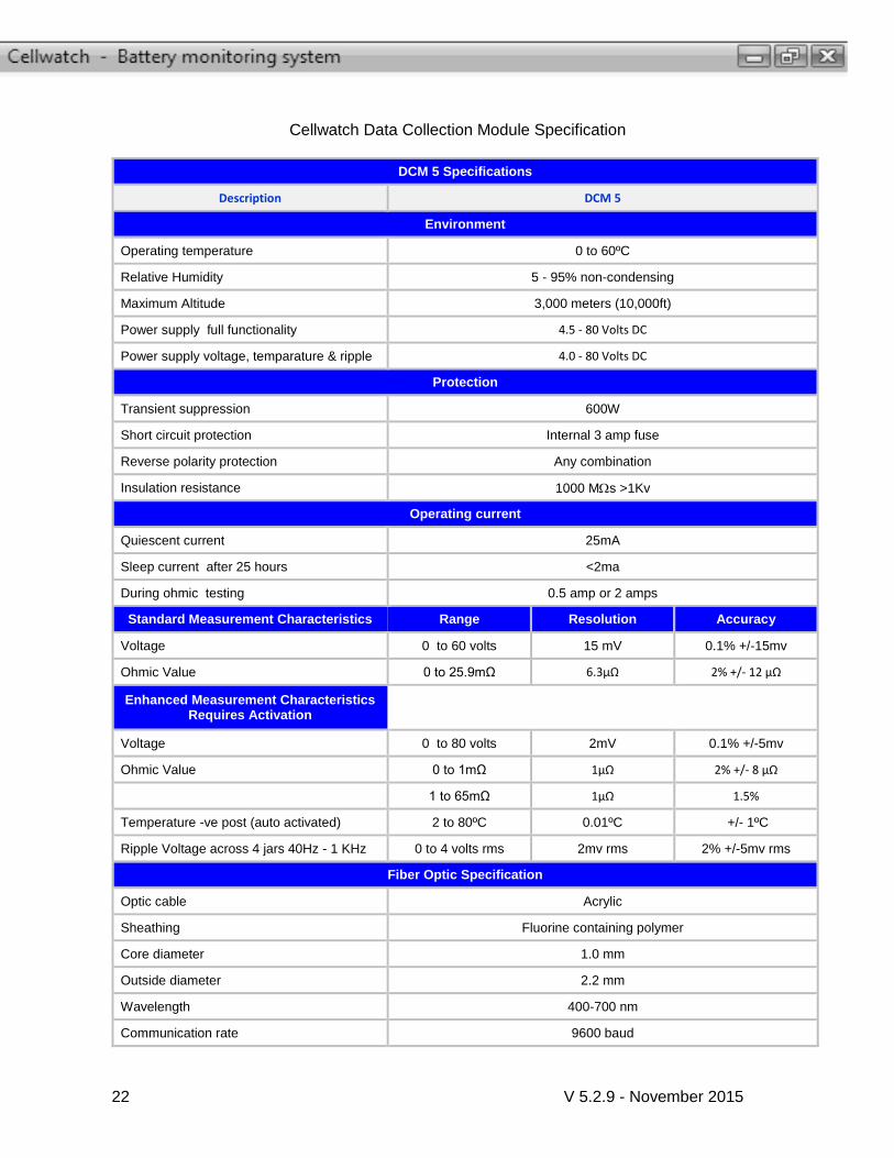
Cellwatch Data Collection Module Specification
DCM 5 Specifications
Description DCM 5
Environment
Operating temperature 0 to 60ºC
Relative Humidity 5 - 95% non-condensing
Maximum Altitude 3,000 meters (10,000ft)
Power supply full functionality 4.5 - 80 Volts DC
Power supply voltage, temparature & ripple 4.0 - 80 Volts DC
Protection
Transient suppression 600W
Short circuit protection Internal 3 amp fuse
Reverse polarity protection Any combination
Insulation resistance 1000 Ms >1Kv
Operating current
Quiescent current 25mA
Sleep current after 25 hours <2ma
During ohmic testing 0.5 amp or 2 amps
Standard Measurement Characteristics Range Resolution Accuracy
Voltage 0 to 60 volts 15 mV 0.1% +/-15mv
Ohmic Value 0 to 25.9mΩ 6.3µΩ 2% +/- 12 µΩ
Enhanced Measurement Characteristics Requires Activation
Voltage 0 to 80 volts 2mV 0.1% +/-5mv
Ohmic Value 0 to 1mΩ 1µΩ 2% +/- 8 µΩ
1 to 65mΩ 1µΩ 1.5%
Temperature -ve post (auto activated) 2 to 80ºC 0.01ºC +/- 1ºC
Ripple Voltage across 4 jars 40Hz - 1 KHz 0 to 4 volts rms 2mv rms 2% +/-5mv rms
Fiber Optic Specification
Optic cable Acrylic
Sheathing Fluorine containing polymer
Core diameter 1.0 mm
Outside diameter 2.2 mm
Wavelength 400-700 nm
Communication rate 9600 baud

23
Fiber optic range Min: 150mm (6”) to Max: 50meters (150 ft)
Mechanical
Dimensions 4.2" x 3.1" x 0.9" 107mm x 80mm x 23mm
Mounting pads 3M Dual Lock™
Optional base plate with mounting holes
Optional base plate with DIN rail mount
Enclosure Material ABS
Wire lead length 36 - 72 inches
Fiber Optic Cable Network
The primary function of the fiber optic network is to supply a highly efficient medium, which allows for ease of installation and safety in operation. The supplied cable is acid resistant, highly isolated, and immune to electrical noise. The fiber optic network enables serial connection or ‘daisy chaining’ of the DCMs. The fiber optic cable joins each DCM serially to the Control Unit. Once reaching the CU, the optic signal is converted at the Control Unit to RS-485 format.
REGULATORY COMPLIANCES
The Cellwatch Control Unit and Data Collection Modules described within this specification are fully compliant with CE regulations for EMC and safety to the following standards:
Emissions and Immunity
EN 61326:1:2006
Safety
EN 61010-1:2010 (3rd edition)
UL 61010-1 2012
CAN/CSA- C22 No. 61010-1-12
cTUVus

24 V 5.2.9 - November 2015
INSTALLATION: OVERVIEW
Note this list is simply an overview. Trained installers can use this as a quick reference to identify the next step in the installation process. The following pages of this manual will walk through these steps in detail.
INSTALLATION CHECK LISTS
Before the installer goes to site he/she should make sure they can answer YES to the following:-
1. Are the people performing install / start-up, trained and have up to date installer badges?
a. Untrained installers can invalidate the warranty on the Cellwatch system
b. There must be at least one installer on site at all times that has a currently valid certification.
2. Do they have an up to date Cellwatch handbook or electronic copy of the manual?
a. Online copies can be found at http://www.cellwatch.com; the print copy should be left at the customer site
3. Have they downloaded any Application Notes from the web?
a. Application notes are released anytime new software or updates are made and may not be included in the printed copy of the manual
4. If connecting to the IBMU locally (keyboard, monitor, and mouse) acquire the components for site and test the IBMU at your office.
a. Optionally users can opt for a KVM (Keyboard, Video, and Mouse) adaptor that physically connects to these ports and consolidates the KVM connections of multiple IBMUs into a single keyboard, monitor, and mouse.
5. If connecting remotely, connect to the IBMU using Remote Desktop using a crossover cable between your laptop and the service port.
a. If possible test the connection while in the office to ensure that when the installer gets to site the IBMU has not suffered from any shipping damage
Once on site, the installation consists of the following tasks:
1. Locate the best position for the Control Units (CUs)
a. NDSL Recommends: A location close to the battery cabinet or rack is best. An open location easily accessible and identifiable. While possible, it is NOT recommended to install the CU in the corner of a room.
2. Locate the best position for the iBMU
a. NDSL Recommends: A location where the IBMU can be permanently mounted if using the wall mount kit or a known location in a rack. The location of the IBMU should be well documented when not in close proximity to the CU so the location is not forgotten several years later. Due to distance limitations, the IBMU should be installed no more than 2000 cable feet from the last CU. Also take into consideration the location and accessibility of the USB ports for future data removal, service, or

25
upgrades to the system. Lastly, ensure accessibility to the IBMU ports for future access. If an IBMU port is not accessible it can greatly restrict your ability to support the product.
3. Make sure all AC power supplies to iBMU, CUs, and TRCs are from UPS supported feeds.
4. Have electrical contractor run conduit from iBMU to CUs and between CUs for low voltage RS-485 communications.
5. Have electrical contractor run conduit from CUs and TRCs to battery cabinets if appropriate.
6. Tab the battery with supplied and properly sized tab washers.
a. NDSL Recommends: Do not install stainless steel washers between tabs and battery straps or posts as this will create voltage drops that may affect readings.
7. Affix DCMs to the battery and attach the wires to the tabs.
a. NDSL Recommends: Do not mount DCMs on the metalwork, rather install DCMs on the jars of the battery or on battery cable trays or covers.
b. When using DCM 5 with optional temperature sensors, install DCMs so that the temperature of the negative post is moniotired.
8. Run the fiber from CU to DCMs, back to CU (white/blue transmit to black receive)
9. Install the temperature probes (TPs)
a. NDSL Recommends: The top of the battery cabinet, the negative post of a pilot cell, or on the top of a jar are ideal locations.
10. Install the current transducers (CTs)
a. NDSL Recommends: Get the orientation for the CT right following the TINAP method. CTs can be scaled for multiple load carrying cables. (See Current Transducer Installation Section).
11. Create a configuration file for the system – run configuration builder
12. Run cables through conduit from iBMU to first CU and from CU to CU – set CU addresses appropriately for multiple CUs as defined in the Configuration File.
13. Start up the system – iBMU should power up and talk to the first DCM – four green bars.
14. Restart Cellwatch & perform the first scan and review the results. – Are the scan results sensible with no unknown or unexplainable anomalies like an inter-tier link?
15. Set up the alarms for each string. Note the auto-set feature will set ohmic value alarms for the entire system
16. Train the end user on how to use the Cellwatch GUI interface.

26 V 5.2.9 - November 2015
CRITICAL DISTANCES
There are very few numbers to remember when specifying or installing Cellwatch relating to distance. The RS-485 serial bus in total is only rated up to 2,000 (600 meters) feet in total length. This can also be interpreted as from the start to the end of the serial bus or total cable feet from the last CU to the iBMU can only be 2,000 ft. There may be up to 31 device addresses on a single RS-485 communications bus for the Cellwatch system. Note if using the Fiber Optic Extender kit function in the CU or TRC 2 device addresses will be utilized.
The second distance is the length of any segment of fiber optical cable run or any CT or TP cable. It can be as much as 150 feet between components.
The Fiber Optic Extender Kit if used can be used to extend the serial fiber optic loop to DCMs in remote locations such as substations, switchgear boxes, or at the generators. This can extend a fiber optic loop up to 4,000 feet over standard, dedicated CAT5 or CAT6 copper cable.
DCM modules have factory crimped wires measured to 36 inches for DCM 2 and DCM EX models) inches. DCM 5 modules can be ordered with factory crimped 36 inches or 72 inch wires. Do not cut and re-crimp these connections. Extensions for DCM2, DCM EX and DCM 5 with 36 inch leads can be purchased separately to allow the DCM to span a greater distance. Keep all operational voltages within specification. Do not extend the Blue and White wires on a DCM beyond the factory installed length.
TRCTRCTRC
Dedicated Cat 5e cable to Genset Remote
Max Copper Distance 4,000 ft.
Maximum Fiber Segment
(CU to DCM, DCM to DCM, DCM to CU)= 150 ft. maximum
Maximum CT Probe Distance
= 150 ft. maximum
Maximum TP Probe Distance
= 150 ft. maximum
DCM to battery terminal distance= 36 in. maximum
Positive battery terminal to negative battery terminal distance
= 72 in. maximum
OI
Cellwatch FO Extender
Dedicated RS-485 IBMU to Last CU on Bus = 2,000 ft. maximum
Cellwatch Critical Distances
Genset Remote
The drawing above illustrates all critical distances for a Cellwatch system.

27
PHYSICAL MOUNTING AND LOCATION - GENERAL
Installation should be carried out by competent qualified engineers in accordance with all relative Health and Safety Regulation and NDSL procedures.
All system components are to be installed to a system design agreed upon by all parties involved in a contract.
Cable entry to the steel cabinets used for housing the Battery Monitoring Unit and Control Unit, should be via properly installed conduit, or cable entry glands. When making entry points into those cabinets, ensure that the integrity and strength of the cabinets is not impaired. Also ensure to remove the circuit boards if exposed to prevent damage or possible shorts from metal shavings that could accumulate. The system is not designed to withstand sprayed liquids, either continuously or intermittently (for instance for cleaning purposes). Ensure that the components are not mounted where water or other liquids will be sprayed or may at any time be present.
CU Cabinet Mounting Overview
The CU is supplied with fittings appropriate to for two types of mounting.
Supplied with each cabinet are the following items1:-
Qty. 4 minimum 12x1 ¾” steel screw, combination head.
Qty. 4 minimum plastic masonry wall mounts.
Qty. 4 minimum SAE ¼” flat steel washer.
Qty. 4 minimum ¼”x20x1” round head steel machine screw.
Qty. 4 minimum ¼”x20 Hexagonal steel nylon insert, self-locking nut.
The installer will also need:
For masonry fixings:
5/16” (8mm) masonry drill (carbide tipped or similar)
Cross head (Phillips, Pozi-drive) screwdriver, size 2
o For sheet steel mounting surface:
5/16” (8mm) high speed drill
Cross head (Phillips, Pozi-drive) screwdriver, size 2
o Wrench, hexagonal size 7/16” AF
Note. Fixing should only be attempted by a qualified installer, equipped and using appropriate safety equipment, especially eye protection. Ensure all power cables in the vicinity of drilling are isolated.
1 note, In UK and Europe, metric equivalents will be provided.

28 V 5.2.9 - November 2015
CABINET MOUNTING
INSTRUCTIONS - GENERAL
Masonry wall.
Hold cabinet (either iBMU or CU) against wall, check for position and square.
Mark, using a pencil or appropriate marker through the cabinet corner mounting holes, the location of the four holes onto the wall.
Move the cabinet well away from the area to be drilled to ensure no drilling debris enters the cabinet.
Drill the four holes with the carbide tipped drill bit in a suitable electric tool to a depth of approximately 2 inches.
Place the plastic wall plugs supplied into each of the holes and tap home until there is no protrusion.
Place the cabinet back against the wall and starting with one of the two top mounting holes, place a washer on the 1½” screws provided and drive almost all the way home into the wall plug.
Repeat until all 4 corners are loosely fixed. Tighten all screws.
Clean out any debris that may have collected in the cabinet.
Sheet steel fixing.
Hold cabinet (either iBMU or CU) against steel surface, check for position and square. Mark, using a pencil or appropriate marker through the cabinet corner mounting holes, the location of the four holes onto the wall.
Move the cabinet well away from the area to be drilled to ensure no drilling debris enters the cabinet.
Drill the four holes with the high speed drill bit in a suitable electric tool.
Place the cabinet back against the surface and starting with one of the two top mounting holes, place a washer on the 1” machine screws provided and insert through the cabinet and the sheet steel mounting surface.
Attach nut to rear of machine screw using 7/16” wrench.
Repeat until all 4 corners are loosely fixed. Then tighten all screws and nuts.
Clean out any debris that may have collected inside the CU cabinet.

29
INSTALLATION: CELLWATCH IBMU
Installation should take place as part of the Cellwatch Battery Monitoring System installation and should only be carried out by a qualified Cellwatch installer.
The iBMU should be installed either in a standard 19” rack mounting enclosure, or mounted on a wall using the iBMU Wall Mount Adapter Kit. Network access is highly recommended, but not required.
When fitted in a rack enclosure, care should be taken to ensure that airflow is not impeded. The IBMU is a solid state device with no fans. Take care to ensure vents are not blocked by obstructions such as wires or equipment.
RACK MOUNTING
Due to the large variations in rack fittings from different manufacturers, the rack mounted IBMU is NOT supplied with fixings. The IBMU should be adequately supported in the rack using shelf supports and retained in place with retaining fixtures. Mounting rails are available for purchase.
Contact your racking supplier for suitable shelf supports and retaining fixtures.
The IBMU is a 2U height.
WALL MOUNTING
When fitting to a wall using the optional NDSL Wall Mounting Kit ensure there is adequate space around the iBMU to allow airflow. Allow at least 4” between the sides, top and bottom of the unit, and any adjacent surfaces.
In particular allow enough space to access the USB and power ports in the front of the unit.
The unit should be mounted with the cable connections to the bottom of the unit and with the two support brackets secured to the wall at the top of the unit (see illustration).

30 V 5.2.9 - November 2015
Wall Kit Mounting Instructions
The wall mounting kit comprises two upper brackets and a lower main body as shown on the left, complete with a bag of fasteners. Mounting hardware for the wall is not provided. Use the necessary hardware for concrete, drywall, wood, or other surfaces as required.
The lower bracket enclosure has a hinged door for concealing the cables and other material at the back or bottom of the iBMU. Cables/conduit should be brought through the holes already pre-drilled in the bracket enclosure.
The top ‘L’ brackets are mounted with the 4 of 10 x 32 screws supplied to the 19” rack mounting ears and used to fix the iBMU to a wall or panel.
Prepare the iBMU Chassis.
Take the iBMU main body and place it on a secure horizontal surface with the yellow label facing upwards.
Fix the angled ‘L’ brackets to the mounting flange of the iBMU with the four 10x32 screws provided.
The wall side of the iBMU is the bottom or non-labeled side. Ensure the ‘L’ brackets are mounted under the iBMU flanges with the wall mounting hole towards the bottom or non-labeled side of the iBMU as shown in the sketch here.
Hold the iBMU carefully against the wall in the correct position ensuring there is sufficient room for USB components (USB flash drive or mouse) at the front of the unit. Mark where the two top wall mounting holes need to be.
Take the iBMU away from the wall and protecting it from dust and drill debris, drill the wall and use the appropriate wall fixing (not supplied) to mount the iBMU by the top fixings to the wall.
Position the bottom bracket over the bottom of the iBMU – note the cover slides around the iBMU. Mark the holes, drill the holes as above and fix.
CONNECTING RS-485 TO THE IBMU
The present RS-485 communications adaptor is shown below. This adaptor connects directly into the RS-485 communications port on the iBMU. Older models may have used a RS-232 to

31
RS-485 converter. If upgrading an existing system to a new IBMU, remove the old hardware and connect the RS-485 adaptor. The Control Unit may need to be rewired to remove the +12v that was required to power the legacy RS-232 to RS-485 converter. Information about previous adaptors can be found on our appnotes page at: http://www.cellwatch.com/appnotes.
RS-485 Adaptor
Uses an internal card and simple connector.
For wiring, see Application Note 20060105
The image below shows the rear view of iBMU showing the correct RS-485 COM port. The RS-485 adaptor should be connected into the exposed (uncapped) DB-9 connector on the back of the IBMU. If two ports are available, only one port can be used at any given time.
CONNECTING AN IBMU TO A CORPORATE NETWORK
The iBMU forms an important and integral part of the Cellwatch Battery Monitoring system which operates using the Windows Embedded operating environment. Many people consider the iBMU a server due to the design of the iBMU the unit should be considered a dedicated battery monitoring system.
The iBMU is set up specifically to enable the Cellwatch software application to run without user intervention in the event that the power is removed and reapplied to the iBMU, such as in a prolonged power failure. For this reason we recommend that network administrators and users read and heed the following information very carefully before changing settings and creating users on any Cellwatch iBMU.
Network Security
The iBMU comes in an unsecured form. There is no virus protection provided on the system. The network settings are set for the iBMU to obtain an IP address as soon as it is plugged into an Ethernet network (There is a default static IP address configured for installation purposes).
COM 1 RS-485

32 V 5.2.9 - November 2015
Anyone plugging the iBMU into their corporate network should plan to install virus protection and manually carry out some Windows updates prior to or quickly following connection to a corporate network. Automatic Windows updates are disabled by default to prevent updates being installed during critical events such as discharges, which require a reboot and stop Cellwatch from functioning until Windows recovers.
Settings
The only user (apart from default users such as Administrator) account established in the factory on the iBMU is Cellwatch whose password is cellwatch. This user should be left as an Administrator. This ID and password are not immediately apparent to the user due to a registry edit that has allowed the system to boot automatically using these credentials. This function is designed to automatically log Cellwatch straight into its desktop where the Cellwatch software application will immediately run and battery scanning will automatically take place. More importantly this is configured so that Cellwatch can automatically boot and begin scanning the batteries should the IBMU lose power due to UPS failure or power loss. THIS IS AN IMPORTANT & ESSENTIAL FEATURE OF Cellwatch AND SHOULD NOT BE ALTERED.
Remote access
NDSL recommends the native Windows software, Remote Desktop, for remotely connecting to an iBMU. The default user and password are cellwatch and cellwatch.
When using Remote Desktop it is very important to use the disconnect option rather than the log off option. Logging off Remote Desktop will log out the Cellwatch user account and close the Cellwatch software. Cellwatch will not be monitoring the batteries if the user has logged off the cellwatch account. Instead use the disconnect feature which continues the user session and simply disconnects the remote desktop connection to the IBMU.
If a network is trying to maintain high integrity and security and does not want the Cellwatch iBMU to be installed on the network, then a hardware based remote monitoring solution is still available across the network. NDSL has tested a single port KVM-over-IP solution from Award (www.ami.com/kvm). This solution allows visibility and control of the iBMU over the network without plugging the network into the iBMU. It simply transmits video, mouse and keyboard signals over the network. NDSL does not recommend a specific brand but has tested this functionality.
Other Options
Some third party applications or services can be used to connect to the iBMU. Applications such as TeamViewer and GoToMyPC are commercially available and typically are capable of navigating safely through corporate firewalls. In some situations these have been coupled with a dedicated mobile AirCard or separate DSL or Cable modem connection providing access to the iBMU.
Legacy Remote Access
Previously iBMU units were shipped with PCAnywhere for connecting to remote systems. Please refer to the application note available at http://www.cellwatch.com/appnotes if you need additional information on PCAnywhere. PCAnywhere was discontinued in early 2014.
NOTE: Always disconnect from the remote session and never use the logoff function. Logging out of the user account on the iBMU will close the Cellwatch application, Data Manager, and close the alarms database. This will stop Cellwatch from scanning.

33
Other features
Cellwatch comes with a built in HTTP web server with both secure or open capabilities. This is turned on from the Cellwatch software screen and allows remote users to view the data from Cellwatch. The information is refreshed every 10 seconds (by default but this setting may be modified). This web server allows read only or ‘push’ and download of data and is available on port 80. The port can be adjusted in the Cellwatch.ini file if necessary.
The optional EmailAlert feature is a fully featured alarm alerting system that works via email. It can use either a network SMTP or a dial up connection or both (cascaded, network first). It uses its own send-mail program and does not receive emails in any way so should not present a security problem. This product can be uninstalled if the customer considers this a security risk.
An optional SNMP client is also available for integration into a building management system. The SNMP agent requires network access as well as the Modbus TCP/IP capabilities on the IBMU to be enabled.
Password summary.
The following chart includes all password that have ever been used with the Cellwatch system.
Feature User ID Password
Windows user account Cellwatch cellwatch
Windows Remote Desktop Cellwatch cellwatch
PCAnywhere (Pre July 2014) cellwatch cellwatch
Cellwatch application deafcat
Web server secure page cellwatch deafcat
Modbus TCP/IP deafcat
CONNECTING TO AN IBMU
This will be covered later in the manual. Please reference the Software section for instructions on how to connect to an IBMU.
POWERING AN IBMU
A suitable, clearly labeled and identified, safety isolation switch should be selected and fitted into the feeds to the CU and iBMU. Both the CU and iBMU should have feeds from a UPS supported power source. All cabling to the CU and iBMU should be installed via grounded metal conduit.
Each IBMU is configured with an auto-switching power supply that will synchronize with incoming 100 to 240 V AC at either 50 or 60 Hz before powering the iBMU. Once synchronized, power will be applied to the iBMU Motherboard allowing the system to boot.

34 V 5.2.9 - November 2015
INSTALLATION: THE CONTROL UNIT (CU) OR THERMAL RUNAWAY CONTROLLER
Thermal Runaway Controller Inputs and Outputs (this represent the Control Unit Inputs and Outputs as well)
TRC Relay OutputsCU Relay Outputs
OV
Sp
are
Fu
se
V
Power Supply
Relay #1
Probe #2
Probe #1
Probe #4
Probe #3
Sensor #2
Sensor #1
Sensor #4
Sensor #3
RS 485RS 485
Terminat ion
Opto Out
Opto In
Curr
ent
Te
mp
era
ture
Reset switch
Fuse
3 pin RS485 from
control unit to control
unit
1=B=white/blue
2=A=blue/white
3=Gnd=white/orange
3=Outer screen one
end only
1 1
1
1
1
1 1
1 1
Temperature probe
connections
1=red
2=blue
3=green
3=Screen
Current probe
connections
1000AMP 2500AMP
1=red red
2=blue/scn black/scn
3=white white
4=yellow green
(scn= cable screen)
Note Jumper positions are different for the last
Control Unit on the end of the RS485 bus.
Last CU: All other CUs:Neutral
connection
Live
connection
14 AWG Cable rated at 600 VACTie line GROUND directlyto cabinet ground block.
614032 A
1
Address Select Switches
Power Socket
1- Ground
2 - +12v
3- Unused
Genset
Connector
Dedicated
connection
for the
Genset
Extension Kit
T C W
TR
1
TR
2
TR
3
TR
4
TR
W
1
Relay Connections
1 – NC
2 – NO
3 – COM
Relay 5 will activate if
no RS-485 act ivity
occurs in 1 hour
See Manual for TRC
Relay Output operat ion
1
AC Connector
GND
connection
1's10's
1's10's
Primary Address is the CU or TRC address.
Genset Address is typically the Primary
Address + 1
Address of ‘0’ ‘0’ will disable the
Genset
Genset
Primary
1

35
There are three types of input and outputs to and from the Control Unit PCB. These are:-
Mains power inputs
Low voltage inputs and outputs
Fiber optic connections
These are described later.
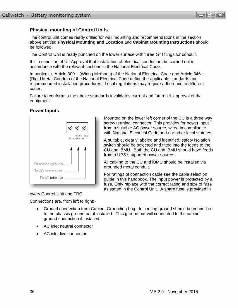
36 V 5.2.9 - November 2015
Physical mounting of Control Units.
The control unit comes ready drilled for wall mounting and recommendations in the section above entitled Physical Mounting and Location and Cabinet Mounting Instructions should be followed.
The Control Unit is ready punched on the lower surface with three ¾’’ fittings for conduit.
It is a condition of UL Approval that installation of electrical conductors be carried out in accordance with the relevant sections in the National Electrical Code.
In particular, Article 300 – (Wiring Methods) of the National Electrical Code and Article 346 – (Rigid Metal Conduit) of the National Electrical Code define the applicable standards and recommended installation procedures. Local regulations may require adherence to different codes.
Failure to conform to the above standards invalidates current and future UL approval of the equipment.
Power Inputs
Mounted on the lower left corner of the CU is a three way screw terminal connector. This provides for power input from a suitable AC power source, wired in compliance with National Electrical Code and / or other local statutes.
A suitable, clearly labeled and identified, safety isolation switch should be selected and fitted into the feeds to the CU and iBMU. Both the CU and iBMU should have feeds from a UPS supported power source.
All cabling to the CU and iBMU should be installed via grounded metal conduit.
For ratings of connection cable see the cable selection guide in this handbook. The input power is protected by a fuse. Only replace with the correct rating and size of fuse as stated in the Control Unit. A spare fuse is provided in
every Control Unit and TRC.
Connections are, from left to right:-
Ground connection from Cabinet Grounding Lug. In coming ground should be connected to the chassis ground bar if installed. This ground bar will connected to the cabinet ground connection if installed.
AC inlet neutral connector
AC inlet live connector
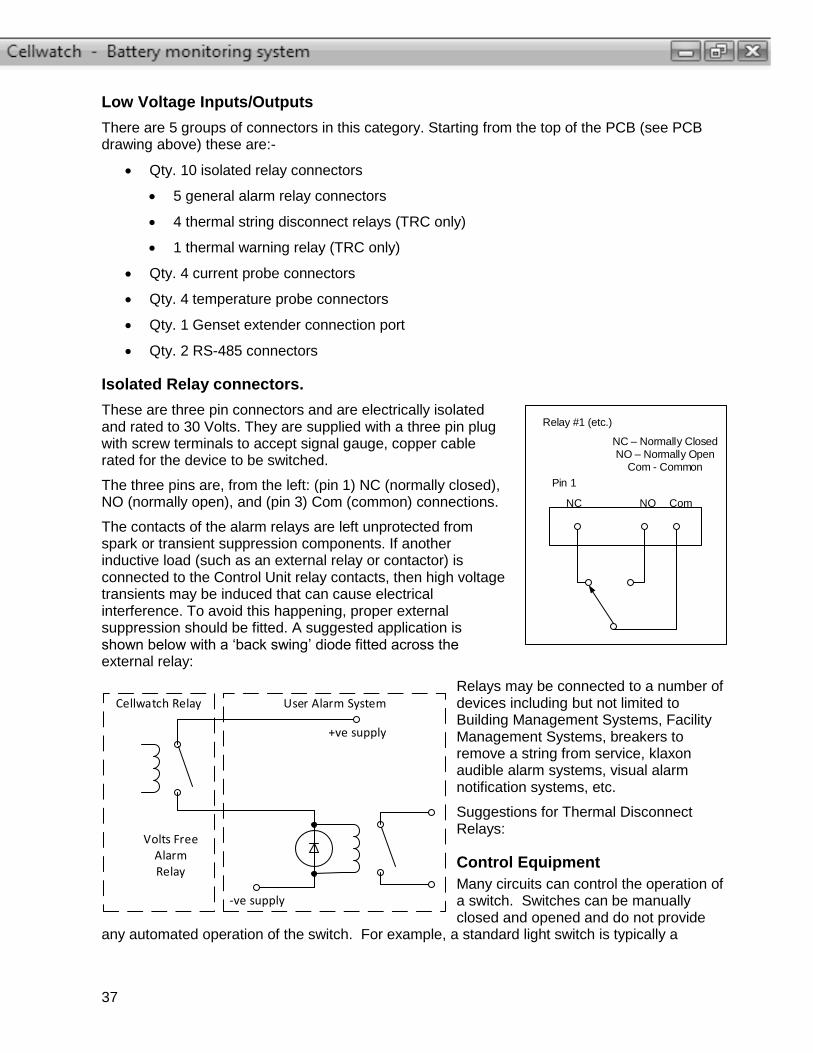
37
Low Voltage Inputs/Outputs
There are 5 groups of connectors in this category. Starting from the top of the PCB (see PCB drawing above) these are:-
Qty. 10 isolated relay connectors
5 general alarm relay connectors
4 thermal string disconnect relays (TRC only)
1 thermal warning relay (TRC only)
Qty. 4 current probe connectors
Qty. 4 temperature probe connectors
Qty. 1 Genset extender connection port
Qty. 2 RS-485 connectors
Isolated Relay connectors.
These are three pin connectors and are electrically isolated and rated to 30 Volts. They are supplied with a three pin plug with screw terminals to accept signal gauge, copper cable rated for the device to be switched.
The three pins are, from the left: (pin 1) NC (normally closed), NO (normally open), and (pin 3) Com (common) connections.
The contacts of the alarm relays are left unprotected from spark or transient suppression components. If another inductive load (such as an external relay or contactor) is connected to the Control Unit relay contacts, then high voltage transients may be induced that can cause electrical interference. To avoid this happening, proper external suppression should be fitted. A suggested application is shown below with a ‘back swing’ diode fitted across the external relay:
Relays may be connected to a number of devices including but not limited to Building Management Systems, Facility Management Systems, breakers to remove a string from service, klaxon audible alarm systems, visual alarm notification systems, etc.
Suggestions for Thermal Disconnect Relays:
Control Equipment
Many circuits can control the operation of a switch. Switches can be manually closed and opened and do not provide
any automated operation of the switch. For example, a standard light switch is typically a
NO ComNC
Relay #1 (etc.)
Pin 1
NC – Normally ClosedNO – Normally Open
Com - Common
+ve supply
-ve supply
Cellwatch Relay User Alarm System
Volts Free Alarm Relay

38 V 5.2.9 - November 2015
manually thrown switch that either opens or closes a circuit. The Cellwatch Thermal Runaway Controller is not compatible with these switches and Cellwatch will not be able to isolate a string without removing the charger from operation. Switches can also be fully automated where using electromechanical equipment to both open and close the breaker. The Cellwatch Thermal Runaway Controller is not compatible with these switches and Cellwatch will not be able to isolate a string as the string may return to operation seconds after the signal is removed. Many switches however will allow a breaker to open for safety reasons and will not close automatically. These switches use an electromechanical or electromagnetic force to maintain a closed state. Once a signal is applied or removed, depending on the operation of the switch, the charged device is released forcing the string to go offline while leaving the charger in operation. The Thermal Runaway Controller is designed to operate with these switches.
Shunt Trip Disconnect
A shunt trip allows for remote disconnection of the UPS string from the charging circuit often signaled by relays elsewhere in the installation. Voltage ratings for shunt trips can vary from 24V AC or DC to 48V DC, and in some cases 120 VAC. Requirements may vary depending on the switch installed. For voltages beyond the relay rated 30V AC/DC a conversion circuit will be required to modify the signal to the correct voltage to properly trip the disconnect switch.
Under Voltage (UV) Trip Device
An under voltage trip device is an electromechanical control that manages the state of the switch. Usually this the component consists of a motor charged spring. As long as the voltage applied to the UV trip is maintained to a certain percentage of the rated value the switch will remain in the closed position (spring engaged and charged). Once the voltage drops to a certain level, the electromagnetic fields within the device are broken forcing the breaker to open (spring discharged and disengaged). Voltage must return to certain levels of the UV device to create a magnetic field strong enough to hold the breaker when it is manually closed. UV Trip devices are typically rated to 48 VDC, 125 VDC, 250 VDC, 120 VAC, and 240 VAC. For voltages beyond the relay rated 30V AC/DC a conversion circuit will be required to modify the signal to the correct voltage to properly trip the disconnect switch.
UPS Digital Input
Some UPS systems contain the ability to isolate the string from the UPS remotely simply by pressing an on-screen button. Configurations such as this may incorporate devices mentioned above, but the control of these devices is managed by an onboard computer. These can be used to isolate the string manually or automatically if certain conditions exist (ex. The string voltage drops dangerously low for the UPS).
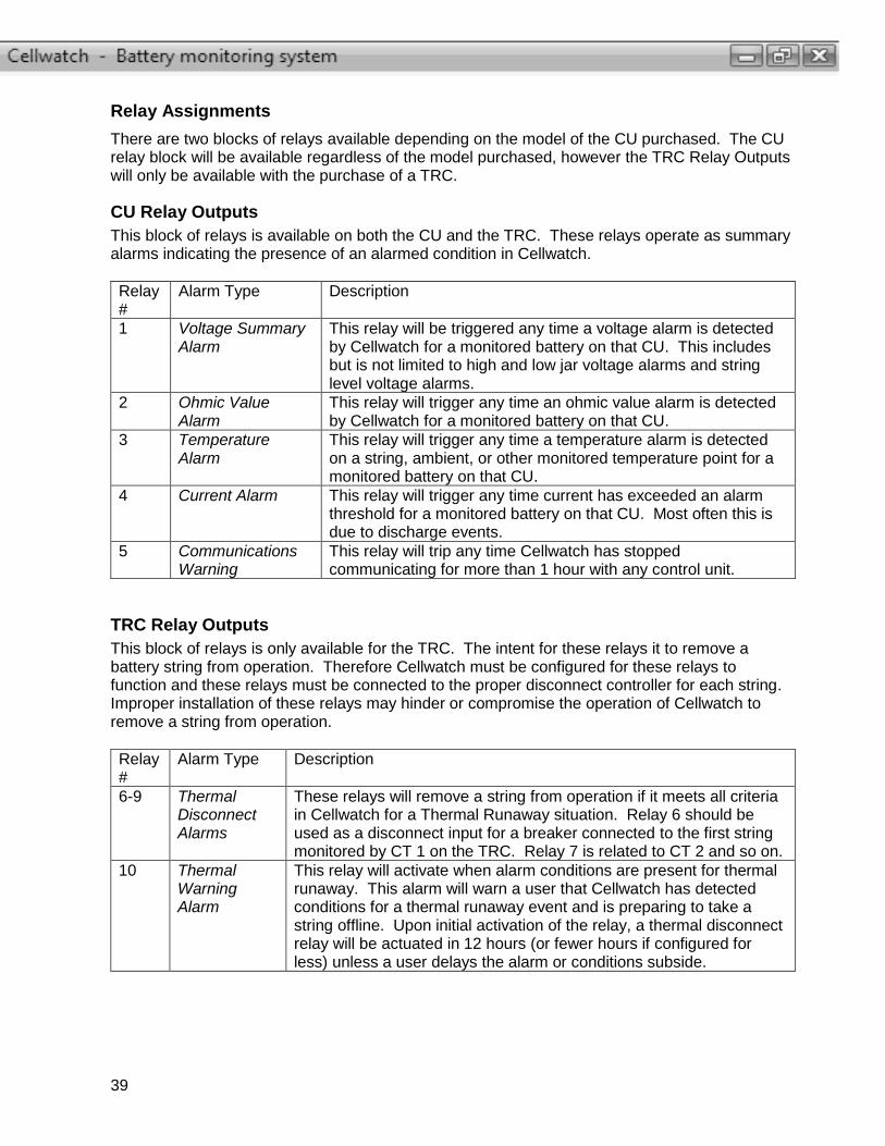
39
Relay Assignments
There are two blocks of relays available depending on the model of the CU purchased. The CU relay block will be available regardless of the model purchased, however the TRC Relay Outputs will only be available with the purchase of a TRC.
CU Relay Outputs
This block of relays is available on both the CU and the TRC. These relays operate as summary alarms indicating the presence of an alarmed condition in Cellwatch.
Relay #
Alarm Type Description
1 Voltage Summary Alarm
This relay will be triggered any time a voltage alarm is detected by Cellwatch for a monitored battery on that CU. This includes but is not limited to high and low jar voltage alarms and string level voltage alarms.
2 Ohmic Value Alarm
This relay will trigger any time an ohmic value alarm is detected by Cellwatch for a monitored battery on that CU.
3 Temperature Alarm
This relay will trigger any time a temperature alarm is detected on a string, ambient, or other monitored temperature point for a monitored battery on that CU.
4 Current Alarm This relay will trigger any time current has exceeded an alarm threshold for a monitored battery on that CU. Most often this is due to discharge events.
5 Communications Warning
This relay will trip any time Cellwatch has stopped communicating for more than 1 hour with any control unit.
TRC Relay Outputs
This block of relays is only available for the TRC. The intent for these relays it to remove a battery string from operation. Therefore Cellwatch must be configured for these relays to function and these relays must be connected to the proper disconnect controller for each string. Improper installation of these relays may hinder or compromise the operation of Cellwatch to remove a string from operation.
Relay #
Alarm Type Description
6-9 Thermal Disconnect Alarms
These relays will remove a string from operation if it meets all criteria in Cellwatch for a Thermal Runaway situation. Relay 6 should be used as a disconnect input for a breaker connected to the first string monitored by CT 1 on the TRC. Relay 7 is related to CT 2 and so on.
10 Thermal Warning Alarm
This relay will activate when alarm conditions are present for thermal runaway. This alarm will warn a user that Cellwatch has detected conditions for a thermal runaway event and is preparing to take a string offline. Upon initial activation of the relay, a thermal disconnect relay will be actuated in 12 hours (or fewer hours if configured for less) unless a user delays the alarm or conditions subside.
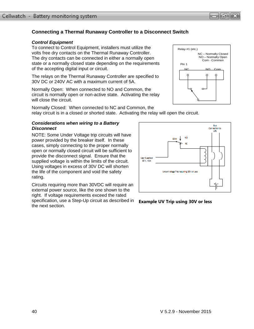
40 V 5.2.9 - November 2015
Connecting a Thermal Runaway Controller to a Disconnect Switch
Control Equipment To connect to Control Equipment, installers must utilize the volts free dry contacts on the Thermal Runaway Controller. The dry contacts can be connected in either a normally open state or a normally closed state depending on the requirements of the accepting digital input or circuit.
The relays on the Thermal Runaway Controller are specified to 30V DC or 240V AC with a maximum current of 5A.
Normally Open: When connected to NO and Common, the circuit is normally open or non-active state. Activating the relay will close the circuit.
Normally Closed: When connected to NC and Common, the relay circuit is in a closed or shorted state. Activating the relay will open the circuit.
Considerations when wiring to a Battery Disconnect
NOTE: Some Under Voltage trip circuits will have power provided by the breaker itself. In these cases, simply connecting to the proper normally open or normally closed circuit will be sufficient to provide the disconnect signal. Ensure that the supplied voltage is within the limits of the circuit. Using voltages in excess of 30V DC will shorten the life of the component and void the safety rating.
Circuits requiring more than 30VDC will require an external power source, like the one shown to the right. If voltage requirements exceed the rated specification, use a Step-Up circuit as described in the next section.
NO ComNC
Relay #1 (etc.)
Pin 1
NC – Normally ClosedNO – Normally Open
Com - Common
Example UV Trip using 30V or less

41
NOTE: If the UPS is configured to remove a single string or multiple strings from operation, Cellwatch will work with these configurations effectively. Some of these configurations may be designed to remove all strings from operation. While this will mitigate thermal runaway, it will also leave the customer exposed without a suitable backup solution.
Example UPS Controlled Multiple String Disconnect
STEP UP CIRCUIT FOR APPLICATIONS REQUIRING > 30 V, 5 A DC
Some circuits require a voltage greater than 30 volts to operate. This can be done various ways, but one of the simplest is a conversion circuit utilizing another relay or dry contact. In the diagram below a user supplied 30V DC can be converted to 48V DC or 120V DC to actuate an Under Voltage Trip by using the closed signal from the TRC to force a closed connection on another dry contact.
-
Bus Connection to
UPS
Cellwatch Dry Contact
+Vs < 30 V, 5 A User Supplied
-Vs
Step Up/Down Relay Circuit
+Ve
-Ve
Connection to UV TripUser Supplied DC Disconnect Voltage
or User Alarm system
Step up Circuit to Modify Signal Voltage

42 V 5.2.9 - November 2015
Current Probe Connectors.
Up to four current probes can be connected to each Control Unit. These are wired, using the color coding of the cables, direct to the 4 pin input connectors supplied. The connectors come ready equipped with four-pin screw terminal plugs. These can be removed from the PCB for easier connection if necessary.
The wiring sequence is shown in the PCB diagram at the start of the CU installation guide. Full description of installation is shown in the following CT Installation section.
Temperature probe connectors
Up to four temperature probes can be connected to each Control Unit, typically one per string. These are wired, using the color coding of the cables, direct to the 3 pin, input connectors supplied. The connectors come ready equipped with three-pin screw terminal plugs. These can be removed from the PCB for easier connection if necessary.
NEVER pull the TP through conduit from the probe itself; always pull the loose wire through conduit. Otherwise the thermistor may become damaged and the TP will not work.
The insulation should be cut back 1” from the end of the cable. The conductors should be stripped ¼” and finger twisted before insertion. The screened outer should be unbraided the stripped 1 inch and inserted carefully along with the green conductor. Ensure the connector secures (bites) on the conductive wire and not the insulation.
The wiring color code is shown on the diagram on the inside of the CU door.
Lightening Protection on TP and CT
For sites where lightening protection is necessary for the application, the shield for both TPs and CTs should be connected to the grounding block in place of the GND connector of the probe port. The Control Unit or the Thermal Controller are not rated to withstand lightning strikes. Wiring the ground in this way helps ensure that the current will flow to ground and is less likely to damage the circuit board.
Auxiliary Power Take Off Connector
There is a three pin plug on the left hand side of the CU for powering accessories. Only approved devices should be connected to this ports.
Control Unit RS-485 connectors
The RS-485 serial data link is designed to connect up-to 31 Control Units to the iBMU in a ‘daisy chained’ manner as shown below. The link is a three cable connection throughout.
NOTE: Genuine Belden 8102 or equivalent cable should be used due to its correct transmission line impedance. CAT5 cable or audio cable should NOT BE USED.
The connections are made in the CU PCB using the removable screw terminal connectors supplied. The recommended cable to be used for all RS-485 connections is Belden 2-pair, 24 gauge, communication cable type 8102 Plenum rated cable (88102) can be substituted for 8102 if required. To prevent reflections in communications, the last CU on the network (CU 2 in the example below), should have its termination jumper in the “in” position.
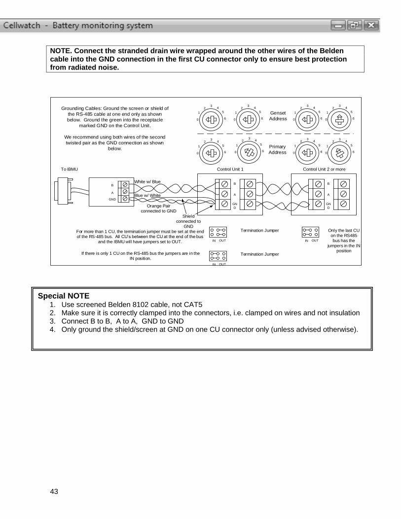
43
NOTE. Connect the stranded drain wire wrapped around the other wires of the Belden cable into the GND connection in the first CU connector only to ensure best protection from radiated noise.
Grounding Cables: Ground the screen or shield of
the RS-485 cable at one end only as shown
below. Ground the green into the receptacle
marked GND on the Control Unit.
We recommend using both wires of the second
twisted pair as the GND connection as shown
below.
B
A
GN
D
B
A
GN
D
Control Unit 1 Control Unit 2 or more
B
A
GND
White w/ Blue
Blue w/ White
Orange Pair connected to GND
Shield connected to
GND
IN OUT
IN OUT
IN OUT
For more than 1 CU, the termination jumper must be set at the end of the RS-485 bus. All CU’s between the CU at the end of the bus
and the IBMU will have jumpers set to OUT.
Only the last CU on the RS485 bus has the
jumpers in the IN position
If there is only 1 CU on the RS-485 bus the jumpers are in the IN position.
Termination Jumper
Termination Jumper
Genset
Address
Primary
Address
To IBMU
0 6
3
1
2 4
5
0 6
3
1
2 4
5
0 6
3
1
2 4
5
0 6
3
1
2 4
5
0 6
3
1
2 4
5
0 6
3
1
2 4
5
0 6
3
1
2 4
5
0 6
3
1
2 4
5
Special NOTE 1. Use screened Belden 8102 cable, not CAT5 2. Make sure it is correctly clamped into the connectors, i.e. clamped on wires and not insulation 3. Connect B to B, A to A, GND to GND 4. Only ground the shield/screen at GND on one CU connector only (unless advised otherwise).

44 V 5.2.9 - November 2015
Multiple Control Units
When there are more than 4 strings monitored, multiple Control Units or Thermal Runaway Controllers should be utilized. If the DCM counts exceed 254 DCMs, or system distances demand it, then multiple Control Units or Thermal Runaway Controllers will need to be specified and installed.
Cellwatch can operate with up to 31 assigned addresses on the RS-485 serial data bus. To identify each CU, TRC, or Genset Kit from any other, each has a manually set address. These addresses are set using two, small rotary switches inside the Control Unit or TRC. The location of these switches is indicated in the illustration on the label inside the controller door.
Control Unit, Thermal Runaway Controllers and Genset Addresses
Control Units and Thermal Runaway Controllers are equipped with an integrated Genset Remote Connector used to monitor generator or switchgear batteries. This is used in conjunction with the Genset Kit sold separately. These units will have two sets of switches, one to select the address of the CU or TRC and one to select the address of the Genset Kit. No two addresses should be repeated. An address of ‘00’ will disable the Genset Remote Connection on the CU.
The Genset Address: The Genset selector
switches allow users to connect a Genset Remote
unit directly to a CU or TRC through dedicated
Ethernet cable.
The Genset cannot have the same address as
any Control Unit as identified in the Primary
Address. Setting the Genset Address to ‘00’ will
disable the Genset extender function of the CU.
It is recommended that the Genset Address be
set to 1 above the Primary address. Ex. For a
primary CU address of 1, the Genset Address
would be 2.
10x 1x
10x 1x
Genset Address
Primary Address
0 6
3
1
2 4
5
0 6
3
1
2 4
5
0 6
3
1
2 4
5
0 6
3
1
2 4
5
Setting Primary and Genset Addresses
One switch is used to indicate the 10’s unit of the address, the other switch sets the single unit number of the address. Hence all addresses are defined by a 2 digit number starting at 01 and will be determined by those two switches as shown in the chart below:-
Bus Address 1 2 3 4 5 6 7 8 9 10 11 12 31
10’s switch 0 0 0 0 0 0 0 0 0 1 1 1 3
1’s switch 1 2 3 4 5 6 7 8 9 0 1 2 1
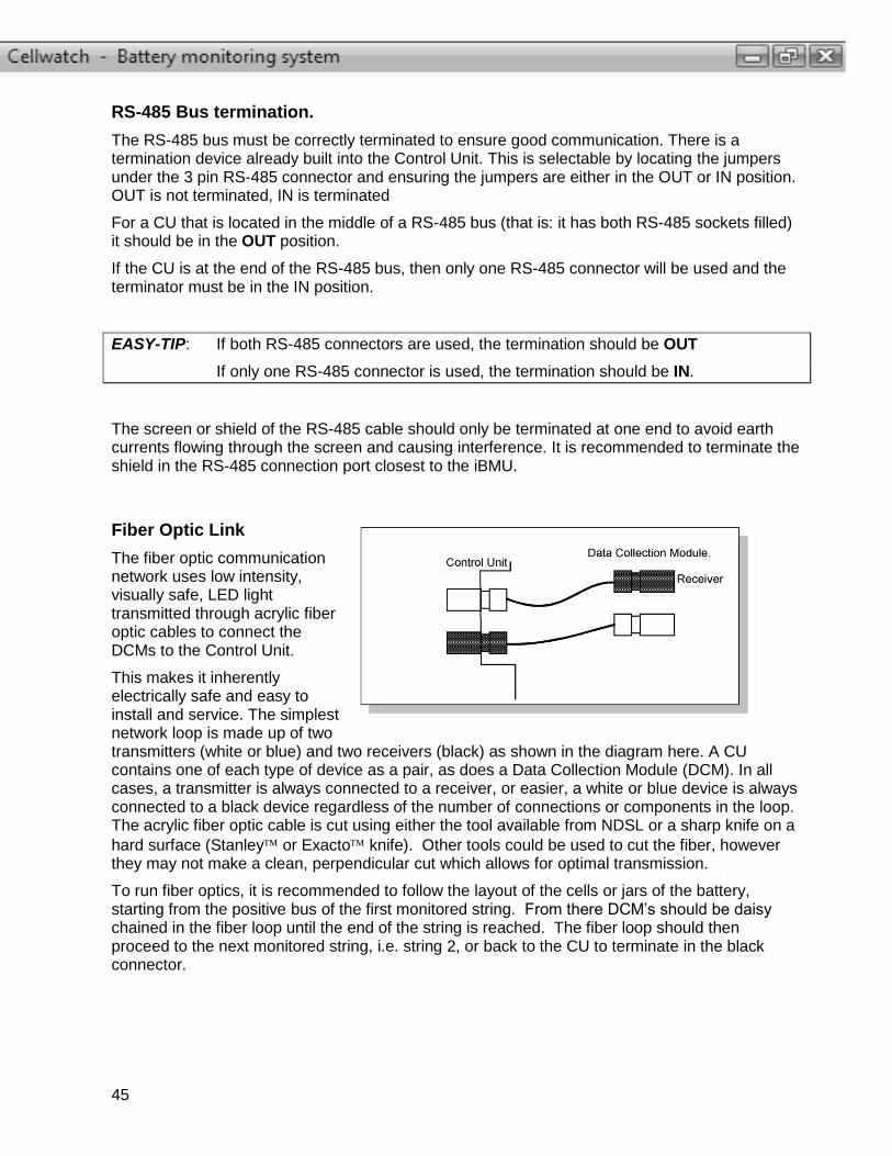
45
RS-485 Bus termination.
The RS-485 bus must be correctly terminated to ensure good communication. There is a termination device already built into the Control Unit. This is selectable by locating the jumpers under the 3 pin RS-485 connector and ensuring the jumpers are either in the OUT or IN position. OUT is not terminated, IN is terminated
For a CU that is located in the middle of a RS-485 bus (that is: it has both RS-485 sockets filled) it should be in the OUT position.
If the CU is at the end of the RS-485 bus, then only one RS-485 connector will be used and the terminator must be in the IN position.
EASY-TIP: If both RS-485 connectors are used, the termination should be OUT
If only one RS-485 connector is used, the termination should be IN.
The screen or shield of the RS-485 cable should only be terminated at one end to avoid earth currents flowing through the screen and causing interference. It is recommended to terminate the shield in the RS-485 connection port closest to the iBMU.
Fiber Optic Link
The fiber optic communication network uses low intensity, visually safe, LED light transmitted through acrylic fiber optic cables to connect the DCMs to the Control Unit.
This makes it inherently electrically safe and easy to install and service. The simplest network loop is made up of two transmitters (white or blue) and two receivers (black) as shown in the diagram here. A CU contains one of each type of device as a pair, as does a Data Collection Module (DCM). In all cases, a transmitter is always connected to a receiver, or easier, a white or blue device is always connected to a black device regardless of the number of connections or components in the loop. The acrylic fiber optic cable is cut using either the tool available from NDSL or a sharp knife on a
hard surface (Stanley or Exacto knife). Other tools could be used to cut the fiber, however they may not make a clean, perpendicular cut which allows for optimal transmission.
To run fiber optics, it is recommended to follow the layout of the cells or jars of the battery, starting from the positive bus of the first monitored string. From there DCM’s should be daisy chained in the fiber loop until the end of the string is reached. The fiber loop should then proceed to the next monitored string, i.e. string 2, or back to the CU to terminate in the black connector.

46 V 5.2.9 - November 2015
INSTALLATION: THE DCMS
SIMPLE RULES
1. Whenever possible, DCMs should be installed on the monitored jars.
2. Avoid fixing the DCM onto metalwork. Electrical noise is being radiated from the chassis, cabinet or metal rack. This is true even if the rack is supposed to be “Grounded”. If high enough, electrical noise could affect the ability for the DCM to monitor very low ohmic values in the 50 to 100 micro-ohm range.
3. Always put the DCM tab washers next to the battery post or strap and in particular, never put anything made of stainless steel between the battery post and the tab washer. Stainless steel is resistive and may offset readings.
4. Never extend the blue or white wires. Wire extensions, especially on very low ohmic value cells, may add micro-ohms to the measurements. This seems insignificant, however a 10 micro-ohm addition to a 50 micro-ohm cell will appear to be significant.
5. Never install a DCM across a battery breaker or open jumper between two cells. Opening a battery breaker may place very high and sustained DC voltages onto a DCM damaging it.
6. Always dress wires in sticks and not coils. Carefully fold the wires back on themselves and avoid creating loops. Loops create inductors that can cause variability in readings at very low ohmic values.
7. Never loop the cable through the sticks since this will create unnecessary noise on the wires.
PREPARING THE BATTERY
There are a few basic steps that should be taken into consideration when preparing to tab the battery and install the DCMs. While the Dual Lock on the DCM will not harm the battery, some end-customers prefer that DCMs are mounted to another surface like Plexiglas or fiberglass suspended above or close to the batteries. DCMs should not be installed on the metalwork of the cabinet, rack, or stack.
DCM 5 is the only DCM module that can be mounted to DIN Rail.
Tabbing the Battery
Please note: for accurate readings, particularly on low ohmic value cells or jars, ensure connect the DCMs to the tin plated (lead free) copper and brass tab washers provided by NDSL.
Stainless Steel tab washers or dual tab washers should not be used unless by prior agreement with NDSL. Stainless Steel and dual tab washers may generate higher readings due to the higher resistance of the metals and/or common resistances.
Ensure that the tab washers are fitted as close to the post of the cell or jar being measured. Make sure that the tab washers are either against the battery post or against the inter-cell strap.
DO NOT PLACE STAINLESS STEEL WASHERS, NUTS OR ANY OTHER HARDWARE BETWEEN THE TAB WASHERS AND THE BATTERY POST.

47
DCMs will be connected directly to these tab washers. If batteries can be pre-tabbed for Cellwatch the installation process will be much faster. Starting with the most positive post of the battery, then subsequent negative posts tabs will be installed. See the battery configurations section below for installation practices on the various battery configurations. Note that there are two power wires to a DCM. The Brown wire is paired with the Red wire and the White wire is paired with the Blue wire. These wires should not be separated unless the application allows or approval from NDSL is obtained. On posts where two DCMs will be connected to the same post there may be a requirement of 4 or more tabs. On systems where there are two positive and two negative post connections for the jar, the washers and sense wires may be split so that Blue and Red terminate on Post 1 and White and Brown terminate on Post 2. (This is covered in more detail under Considerations for cells with 4 or more posts).

48 V 5.2.9 - November 2015
For systems not divisible by four or where voltage across all four channels of one DCM will be too high, one or more DCMs must ‘null’ channels. To null channels all wires for that channel are terminated on the same post. Channel 4 should always be considered the first channel to be nulled, followed by 3. This will be covered in further detail below. Programming Cellwatch for unused channels is described in further detail in the Configuration Builder section of the manual.

49
Combining wires
For greatest accuracy the electrical connection from red to brown and from white to blue should be made as close to the post of the battery as possible. Due to the load placed through the brown and white wires during the ohmic value scan, common resistances should be avoided if at all possible. Do not attempt to use splitters as described below. Do not attempt to join the paired wires from the DCM or extend the blue and white wires. Any ohmic value that is common to either the red and brown leads or the white and blue leads is added to the channel 1 or 4 reading. This is due to the common resistances that create a voltage drop during the ohmic value scan that will offset the sense wire readings.
In particular do not try to use splitters or any of the joining techniques shown below.
(a)
(b)
(c)
(d)
(c1)
(e)

50 V 5.2.9 - November 2015
Battery Configurations
Battery configurations can vary in a variety of methods. Cabinet vs Rack, jars per tray, size of jars, inter-tier strap or copper bus bars are just a few examples of configurations. There are at least 5 types of battery installation which need slightly different approaches. By understanding these five types any unusual installation can be accommodated.
1. VRLA on a tray in a cabinet
Typically 4x12v jars per tray ranging from 2mΩ to 10mΩ – 40 jars per cabinet
Some configurations may contain 30 or 32 jars per cabinet
2. VRLA on shelves in a cabinet
Typically 12v jars ranging from 2mΩ to 10mΩ
Typically contains 8-10 jars per shelf
3. VRLA on open racks
Typically 6 to 12v jars ranging from 1mΩ to 10mΩ
4. Wet cells on open racks
Typically 2 to 8v jars ranging from 50µΩ to 2mΩ
This configuration must use DCM-EX or later
5. Front access, multi-cell, VRLA stacks.
Typically 2v jars ranging from 50µΩ to 2mΩ
This configuration must use DCM EX or later
Each option above is described in more detail below. This section will not describemany possible configurations.
Special consideration should be given for monitoring jars with an ohmic value below 1mΩ. Pay careful attention with both tabbing and dressing the wires; they will require a little forethought and planning prior to installation.
DCM 5 is the suggested DCM for this application.
Bolt/Tab Sizes
There are several sizes of tab washer available: 3/16’’ (5mm), 1/4” (6.3mm), 5/16” (8mm), 3/8’’ (10mm), and 1/2'’ (12mm). Make sure you have the correct size for the cells you are monitoring.
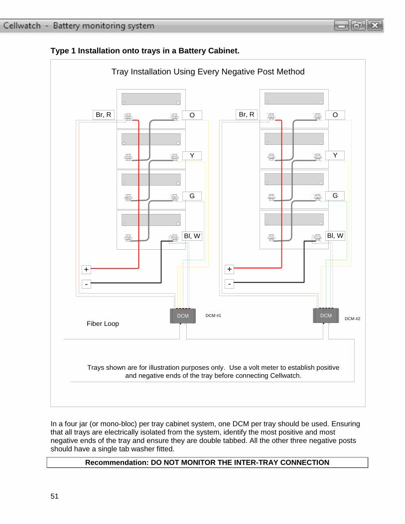
51
Type 1 Installation onto trays in a Battery Cabinet.
DCM #1DCM #2
Fiber Loop
Trays shown are for illustration purposes only. Use a volt meter to establish positive
and negative ends of the tray before connecting Cellwatch.
Tray Installation Using Every Negative Post Method
+ -
+ -
+ -
+ -
+
-
Br, R O
Y
G
Bl, W
DCM
+ -
+ -
+ -
+ -
+
-
Br, R O
Y
G
Bl, W
DCM
In a four jar (or mono-bloc) per tray cabinet system, one DCM per tray should be used. Ensuring that all trays are electrically isolated from the system, identify the most positive and most negative ends of the tray and ensure they are double tabbed. All the other three negative posts should have a single tab washer fitted.
Recommendation: DO NOT MONITOR THE INTER-TRAY CONNECTION

52 V 5.2.9 - November 2015
There should never be any other material between the strap or post and the tab washer. If possible always make sure the tab washer is directly against the lead post of the jar or on top of the load carrying cables. Where double tabs are needed NEVER place any material between the two tabs, never place any material between the two tabs and the post or strap. In particular never place a stainless steel object between the post, strap and tab such as a washer or nut. Stainless is 50x more resistive compared to copper and will affect the measurements.
Starting at the positive end of the tray, connect DCM cables Brown & Red to the positive terminals. Then connect Blue & White to the double tagged negative terminals at the end of the tray. The DCM will flash LED’s and emit a tune. Finally connect Orange, Yellow and Green to the
three negative terminals in that order. The DCM is now installed. Using the 3M Dual-lock provided, stick the DCM to the front of front most block or jar ensuring no safety or other labels are being covered. Dress all DCM cables using the cable ties provided making sticks and not loops with excess cable.
NOTE: We always recommend fixing the DCMs to the insulated battery cases that are being monitored.
Avoid mounting units to the steel chassis.

53
Type 2 & 3, VRLA on shelves in a cabinet or on open racks
A typical shelf in a battery cabinet will have 8 to 10 or even as many as 12 jars per shelf. First be sure that the total number is divisible by 4, otherwise apply the rules described later in the section dedicated to batteries not divisible by four.
For open rack configurations, consider ordering fiber optic cable in the roll. NDSL offers an option for ordering a roll of cable rather than having pre-cut fiber included in the kit. Pre-cut fiber optic cable might not reach between battery racks due to the longer distances.
Tabbing the battery
If the Cellwatch system is to be fitted to a new shelf mounted battery, the ring tabs or tab washers may have to be fitted after the cabinet has been assembled. Always use Cellwatch provided tabs or tabs approved by NDSL for any Cellwatch installation.
There are a number of ways the battery can be connected to the DCMs depending on the space available. The favored method is the “Every Negative Post” method. This will capture every inter-cell link on the battery within Cellwatch’s measurements. However they are connected plan for the DCMs to be mounted on the front of the jars (not on the metal of the cabinet) where the fiber optics is accessible and the LEDs can be clearly seen. If the front of the jars is not possible consider using DIN Rail, the Plexiglas safety shield or the top of the jar avoiding covering the vent.
Every Negative Post method
Connect DCM modules to the battery using the ENP (Every Negative Post Method). It is described below:
1. Tab the most positive terminal of the first jar/cell of the string with 2 tab washers. This is the ONLY positive terminal you will tab.
2. Tab the next 3 negative terminals with single tab washers.
3. Tab the next negative terminal with four washers. This is for the connection of the second DCM and the termination of the first DCM.
4. Repeat steps 2 & 3 until you get to the last negative post of the battery. Put two tab washers on this post.
See the diagram below:

54 V 5.2.9 - November 2015
+-
+-
G
Bl, W
,
Br, R
+-
+-
Br, R
OY
+-
+-
+-
+-
+-
OYG
Bl, W
Every
Neg
ativ
e P
ost M
eth
od
DCM
DCM
Legacy Methods - Every Positive Post method
As described above, the same steps are used except tabs are fitted to the positive posts of every jar and the most negative post of the last jar.
NOTE: This method is not recommended for DCM modules equipped with temperature sensors. Temperature should always be measured on the negative post of the jar or cell.
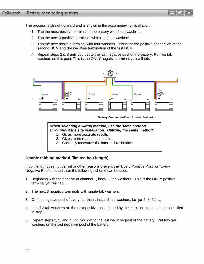
55
The process is straightforward and is shown in the accompanying illustration.
1. Tab the most positive terminal of the battery with 2 tab washers.
2. Tab the next 3 positive terminals with single tab washers.
3. Tab the next positive terminal with four washers. This is for the positive connection of the second DCM and the negative termination of the first DCM.
4. Repeat steps 2 & 3 until you get to the last negative post of the battery. Put two tab washers on this post. This is the ONLY negative terminal you will tab.
Double tabbing method (limited bolt length)
If bolt length does not permit or other reasons prevent the “Every Positive Post” or “Every Negative Post” method then the following scheme can be used.
1. Beginning with the positive of channel 1, install 2 tab washers. This is the ONLY positive terminal you will tab.
2. The next 3 negative terminals with single-tab washers.
3. On the negative post of every fourth jar, install 2 tab washers, i.e. jar 4, 8, 12, …
4. Install 2 tab washers on the next positive post shared by the inter-tier strap as those identified in step 2.
5. Repeat steps 2, 3, and 4 until you get to the last negative post of the battery. Put two tab washers on the last negative post of the battery.
+ + + + + +
Battery Connection: Every Positive Post method.
4 tagsSingle tag Single tag Single tag
4 tags
Single tag
When selecting a wiring method, use the same method throughout the site installation. Utilizing the same method:
1. Gives more accurate results 2. Gives more repeatable results 3. Correctly measures the inter-cell resistance
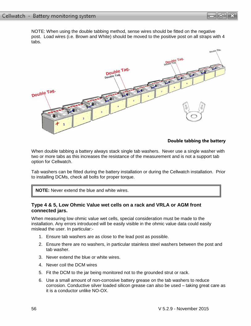
56 V 5.2.9 - November 2015
NOTE: When using the double tabbing method, sense wires should be fitted on the negative post. Load wires (i.e. Brown and White) should be moved to the positive post on all straps with 4 tabs.
Double tabbing the battery
When double tabbing a battery always stack single tab washers. Never use a single washer with two or more tabs as this increases the resistance of the measurement and is not a support tab option for Cellwatch.
Tab washers can be fitted during the battery installation or during the Cellwatch installation. Prior to installing DCMs, check all bolts for proper torque.
Type 4 & 5, Low Ohmic Value wet cells on a rack and VRLA or AGM front connected jars.
When measuring low ohmic value wet cells, special consideration must be made to the installation. Any errors introduced will be easily visible in the ohmic value data could easily mislead the user. In particular:-
1. Ensure tab washers are as close to the lead post as possible.
2. Ensure there are no washers, in particular stainless steel washers between the post and tab washer.
3. Never extend the blue or white wires.
4. Never coil the DCM wires
5. Fit the DCM to the jar being monitored not to the grounded strut or rack.
6. Use a small amount of non-corrosive battery grease on the tab washers to reduce corrosion. Conductive silver loaded silicon grease can also be used – taking great care as it is a conductor unlike NO-OX.
NOTE: Never extend the blue and white wires.
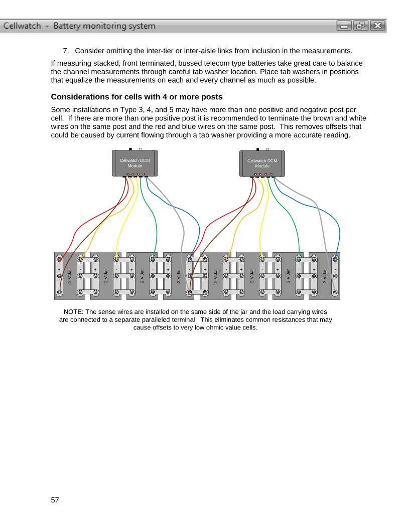
57
7. Consider omitting the inter-tier or inter-aisle links from inclusion in the measurements.
If measuring stacked, front terminated, bussed telecom type batteries take great care to balance the channel measurements through careful tab washer location. Place tab washers in positions that equalize the measurements on each and every channel as much as possible.
Considerations for cells with 4 or more posts
Some installations in Type 3, 4, and 5 may have more than one positive and negative post per cell. If there are more than one positive post it is recommended to terminate the brown and white wires on the same post and the red and blue wires on the same post. This removes offsets that could be caused by current flowing through a tab washer providing a more accurate reading.
2 V
Ja
r
-
+
2 V
Ja
r
-
+
2 V
Ja
r
-
+
2 V
Ja
r
-
+
2 V
Ja
r
-
+
2 V
Ja
r
-
+
2 V
Ja
r
-
+
2 V
Ja
r
-
+
Cellwatch DCM
Module
Cellwatch DCM
Module
NOTE: The sense wires are installed on the same side of the jar and the load carrying wires
are connected to a separate paralleled terminal. This eliminates common resistances that may
cause offsets to very low ohmic value cells.

58 V 5.2.9 - November 2015
Other Considerations
Long inter-tier links
If you have a battery installation that is broken up by long inter-tier or even inter-aisle cables, you need to consider if you want to keep these in the measurement data-set or omit them.
Shown is a graph of a 200µΩ per jar (4v wet cells) battery system whose installer kept a single inter-aisle conductor in the measurement circuit. The ohmic-value of that inter-aisle link is clearly visible on the data and will skew the averages for the entire string. Cellwatch can automatically adjust for this in setting ohmic value alarms. Altering the installation to remove the inter-tier connector can remove readings like this from the graphs, however the ohmic value of the inter-tier connector would no longer be monitored.
Strings or sub-strings not divisible by four (i.e. Null Channels)
Cellwatch DCMs measure four channels of data at a time. If the battery is designed in such a way as to NOT BE DIVISIBLE by four then special techniques must be used that require planning. The methods used are covered extensively in the section on Configuration Builder in this manual. However, here is a brief summary of sub-string configurations.
30 VRLAs in a cabinet
In this configuration 8 DCMs will be required. The 7th DCM only uses channels 1 and 2, channel 3 and 4 are nulled. The blue, white, green and yellow wires are all connected to the negative post of jar 26. Unused leads should always be connected to a battery post so they are secured and never pose a risk to the battery.

59
Ja
r 2
6
-
+
Ja
r 2
5
-
+
Ja
r 2
4
-
+
Ja
r 3
0
-
+
Ja
r 2
0
-
+
Ja
r 2
8
-
+
Ja
r 2
7
-
+
Cellwatch DCM
Module
Cellwatch DCM
Module
For systems with a number of monitoring points not divisible by 4 (see a 30 channel
configuration above) always null DCM channels on the next to last DCM.
Up to Four VRLA jars on a tray
In this configuration, it may be undesirable to monitor the inter-tier connection due to cable routing between shelves. The inter-tier connection is typical a long cable that may include an Anderson or similar connector so that each try may be isolated independently. In this configuration it is recommended that a warning be placed on the front of the cabinet so that the Cellwatch DCM is disconnected prior to opening any of the inter-shelf connectors. If the connectors or inter-tier cables are not monitored, each tray is regarded as a sub-string (see configuration builder). For a four jar per tray configuration the blue and white wires are connected to the most negative end of the tray.

60 V 5.2.9 - November 2015
+ -
+ -
+ -
+ -
+ -
+ -
+ -
+ -
+
-
Every Negative Post Method
Preferred
2 Tabs
Br, R
1 Tab
O
1 Tab
Y
1 Tab
G
2 Tabs
Bl, W
+
-
2 Tabs
Br, R
Every Positive Post Method
Traditional
1 Tab
O
1 Tab
Y
1 Tab
G2 Tabs
Bl, W
For a three jar configuration, channel 4 will be nulled and the green, blue, and white wires are connected to the most negative post of the tray.
16 V x 30 jar configurations
As above, configurations will typically include a cabinet with 3 jars per tray. In these configurations consider each tray as a substring and use 1 DCM per tray. Only DCM 5 can properly handle monitoring 4x 16V jars. For DCM or DCM EX modules ensure the DCM is not subjected to over-voltages it is recommended to null channel 4 on each DCM. This requires that the system use 10 DCMs per cabinet instead of 8 as above in the 30 VRLA jars in a cabinet. DCMs are connected normally with the Green, Blue, and White terminated on the same post. Connecting to 16V jars is covered in more detail later in this manual.
Sub strings of 2 volt wet cells not divisible by four
Overlaps can be used on the next to last DCM on each sub string. The rule is; always null out channel 4 first on a string and then channel 3. Never use overlaps on anything other than 2 volt wet cells.
The ‘Golden Rule’ is that the next to last DCM is always the first DCM to be underutilized (i.e. nulled).
On the next to last DCM, always starts nulling from channel 4, then channel 3, and
if necessary channel 2.
Always consider the operational voltage of the DCM when nulling channels.

61
Connecting the DCMs
Connection order, while important for reliability, is not essential due to extensive, built-in, circuit protection. It is advised however that the two most positive leads are connected first followed by the two most negative leads. When these leads are connected the unit will flash LED’s and ‘Beep’ to signal successful operation.
If all four wires are connected to the 8 volt to 80 volt battery supply and no ‘Beep’ is heard, disconnect the unit and check the installation orientation.
Having ensured that the four outer cables are correctly connected to the battery, connect the center
three connections to the single tabs starting at the negative end and working up to the positive of the three cables (see chart).
Warning: The Data Collection Modules (DCM and DCM EX) are rated for a maximum voltage of 60 Volt DC. The DCM 5 is rated for a maximum voltage of 80 Volt DC.. It is designed with protection circuitry to protect the DCM in the event that it is subject to temporary over-voltage conditions or reverse wiring. However it is not designed to withstand continuous high voltage connection (.i.e. total string voltage 100+ V DC). If battery links are removed during use, it is likely that high voltages will be fed into the DCM and cause irreparable damage.
Always remove the DCM if battery links are to be opened for cell, jar or mono-block replacement. There is always a risk of circuit completion on a battery that can result in the whole battery voltage (sometimes in excess of 500 volts) being placed across one single DCM if a battery or inter-tier link is removed. Never install across a circuit breaker.
DCM 5 modules can connect across 4x Ni-Cad 1.3 V (nominal) cells up to 4x VRLA 16 V (nominal) jars. Older DCM and DCM EX modules can monitor 4x 2V jars up to 4x 12V jars or 3x 16V jars.
DCM 5 or DCM EX should be used to monitor 2V or 4V VRLA or VLA cells. Due to the low ohmic value of these cells, extensions of any sort to DCM leads may cause variances in the ohmic value readings.
NEVER Extend the Blue and White cables. These wires provide the ground reference circuit of the DCM and should not be altered or extended.
DCM Location.
The grounded chassis of battery cabinets or steel battery racks can radiate large amounts of high frequency electrical noise. The DCM is carefully ‘hardened’ against EMC radiation but cannot withstand all radiation. In 1% of cases or less, fixing the DCM directly to a grounded steel cabinet or rack may cause a degradation in data rates, variability in ohmic readings, or in rare cases data

62 V 5.2.9 - November 2015
corruption. It is for this reason that NDSL recommends that the DCM be affixed to the battery with the dual lock strips provided.
TRY whenever possible to affix the DCM to one of the batteries being monitored. Avoid steel cabinets or racks as you don’t know what noise these radiate.
DIN Rail
The DCM 5 can be fitted with an optional mounting bracket that allows the DCM to affix to any standard DIN Rail. It is recommended that the DIN Rail itself be located away from the battery terminals.
Care should be taken in routing DCM wires in these configurations. It is recommended to harness/bundle each DCMs wires together as close as possible to the battery. This allows easy access and removal of a module for maintenance purposes. It is also a good option if there is not enough room on the jar to mount the DCM.

63
DCM Connection Order
The order the wires are installed does not matter to the DCM. For customers that prefer a wiring process, see the tables below. Sometimes the alternate wiring method is used to determine if the DCM has enough voltage to be powered before the other wires are installed. Sequential
Connection order Cable Colors
.
Typical Voltage (2V system)
Typical Voltage (12V system)
1st White Most Negative 0 volts 0 volts
2nd Blue Most Negative 0 volts 0 volts
3rd Green 2 volts 12 volts
4th Yellow 4 volts 24 volts
5th Orange 6 volts 36 volts
6th Red Most Positive 8 volts 48 volts
7th Brown Most Positive 8 volts 48 volts
Alternative
Connection order. Cable Colors . Typical Voltage (2V system)
Typical Voltage (12V system)
1st White Most Negative 0 volts 0 volts
2nd Blue Most Negative 0 volts 0 volts
3rd Brown Most Positive 8 volts 48 volts
4th Red Most Positive 8 volts 48 volts
5th Green 2 volts 12 volts
6th Yellow 4 volts 24 volts
7th Orange 6 volts 36 volts
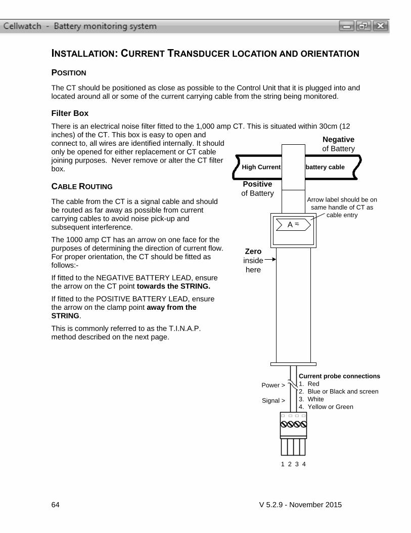
64 V 5.2.9 - November 2015
INSTALLATION: CURRENT TRANSDUCER LOCATION AND ORIENTATION
POSITION
The CT should be positioned as close as possible to the Control Unit that it is plugged into and located around all or some of the current carrying cable from the string being monitored.
Filter Box
There is an electrical noise filter fitted to the 1,000 amp CT. This is situated within 30cm (12 inches) of the CT. This box is easy to open and connect to, all wires are identified internally. It should only be opened for either replacement or CT cable joining purposes. Never remove or alter the CT filter box.
CABLE ROUTING
The cable from the CT is a signal cable and should be routed as far away as possible from current carrying cables to avoid noise pick-up and subsequent interference.
The 1000 amp CT has an arrow on one face for the purposes of determining the direction of current flow. For proper orientation, the CT should be fitted as follows:-
If fitted to the NEGATIVE BATTERY LEAD, ensure the arrow on the CT point towards the STRING.
If fitted to the POSITIVE BATTERY LEAD, ensure the arrow on the clamp point away from the STRING.
This is commonly referred to as the T.I.N.A.P. method described on the next page.
High Current battery cable
Zero
inside
here
A ~
Negative
of Battery
Positive
of BatteryArrow label should be on
same handle of CT as
cable entry
1 2 3 4
Current probe connections
1. Red
2. Blue or Black and screen
3. White
4. Yellow or Green
Power >
Signal >

65
ORIENTATION
A useful acronym to remember for CT orientation is TINAP: Towards If Negative, Away Positive. If fitted in the center of a string the arrow should point towards the most positive post of the string, see illustration.
T. I. N. A. P.
T owards I f N egative, A way if P ositive
+
Current Transducer Arrow Direction
Black CT Red CT
Arrow label should be on the same handle of CT
cable entry
Positive of Battery
Negative
of Battery
Zero adjust is located
underside of this handle
Negative
of Battery
Positive
of Battery

66 V 5.2.9 - November 2015
CONNECTING THE CT TO THE CONTROL UNIT.
The wiring to the Control Unit connector is as follows:-
Red CT 1000 amp Connector Pin No. Black CT 1000 amp
Red 1 Red
Blue & Screen 2 Black & Screen
White 3 White
Yellow 4 Green
CABLE AND CONNECTOR.
As a standard configuration, the current transducers are supplied with 35 feet of cable and connector.
The cable is Belden P/N 8723SB.
EXTENDING CABLE LENGTH.
If required, the length of cable fitted to the clamp may be extended up to a maximum of 150ft. Ensure the shield (screen) of the cable is continuous down the entire length of the cable and is grounded at the Control Unit as shown in the illustration above.
When using these longer cables they should, if possible, be routed inside metal conduit to provide additional screening. If this is not possible, it is essential that they be routed away from heavy current carrying conductors.
Trouble shooting tip: If all your CTs are not working, test the voltage between pin 1 & 2 on the CT connector in the filter box. If you do not measure +12v, (or +11v) you must find and remove the short circuit and try again. The short circuit is probably because of a shorted out GND and +V on the RS-485 connector or component connected to the Control Unit. Often removing all connections and installing them one by one will help identify where short circuits may have occurred.
67
Zeroing CTs
The black 1000 Amp CT does not have any user adjustable controls. The zero level is factory preset. The red 1,000 Amp CT is factory adjusted but may be adjusted in the field using a “zero” control on the handle. This is a multi-turn potentiometer and can be used to re-establish the zero for the CT if the reading taken when OFF the battery cable is not already zero. Note small fluctuations will occur with either CT. Only do this if the reading in Cellwatch diagnostics does NOT average between -1 to +1 amp when NOT ATTACHED TO THE BATTERY CABLE.
Using Cellwatch diagnostics (Diagnostics>System Test>password: deafcat), point to the appropriate CU (CU 1 or CU2 etc.). Press ILA, then SUA, then RVD and read the currents from probes 1 and 2 returned from the CU in the bottom right of screen. XTR will return currents from probes 3 and 4 returned from the CU in the bottom right of the screen. Turn potentiometer on the red CT until current reads between -1 and +1 amp while NOT ATTACHED TO THE BATTERY CABLE.
Scaling CTs
In some cases there may be too many cables to go through the CT or the current draw may be too great to pass all cables through the CT. In these cases Cellwatch is capable of scaling current flow through each CT individually. This means that users can have a single or several CTs that are scaled because they are monitoring a subset of the total installed cables. Let’s assume we attach the CT to 1 of 3 available cables. In this case, Cellwatch would scale the readings so that while the CT is measuring 1/3 of the actual current, the on-screen display is scaled by 3 to show the approximate true current.
Alternately, there are some sites with very low current load. More accurate current flows can be collected by coiling the load carrying wires to increase the signal strength. Cellwatch can be program so that actual current will display properly.
The Configuration Builder will guide the installer through the configuration process. If users need to perform more advanced modifications they should consult the software guide at the rear of this manual.

68 V 5.2.9 - November 2015
INSTALLATION: CABLE TYPES AND RATINGS.
CONTROL UNIT.
The following three tables define the wiring recommendations and maximum ratings of the connection system used on the Control Unit and the Thermal Runaway Controller
All signal connector ratings.
Rated Voltage 300 V maximum.
Rated Current 10 A maximum.
Wire Size Minimum 22 AWG (0.64mm dia)...14 AWG (1.625mm dia) Maximum
Strip Length 0.24" (7 mm)
Torque Nm (lb. in.) 0.25 (2.25)
Power connector ratings
Rated Voltage 300 V maximum.
Rated Current 15 A maximum.
Wire Size Minimum 26 AWG (0.38mm) ...12 AWG (2mm) Maximum.
Strip Length 0.24” (7 mm)
Torque Nm (lb. in.) 0.5 (4.4)
Power Cable Specification.
United States Europe
Cable Temperature rating 90ºc maximum working 70ºc working
Cable voltage rating 600 VAC. working. 450 VAC. working
Input fuse rating 1 Amp. Slow Blow 20mm x 5mm
POWER INPUT CABLES RECOMMENDATIONS
For connection to the Control Unit or Thermal Runaway Controller and the Integrated Battery Management Unit we recommend that you use 12 AWG to 16AWG (European1mm² to 1.5mm²), single or multiple conductor, maximum temperature rating 90ºc, 600V rated (European 70ºC,450V working) installed in conduit. All cable should meet or exceed the requirements for Underwriter’s Laboratories’ type THHN building wire in the US and in Europe must be in accordance with the relevant national standard (BS7671 in the UK).

69
It is essential that the CU and TRC is wired into a UPS backed power supply via conduit. An approved and clearly labeled safety isolation switch should be mounted in the power feed to the CU or TRC close to the equipment. The switch should be rated as 600VAC, 20 Amp and meet or exceed the local requirements.
The Control Unit and Thermal Runaway Controller has a power input fuse. It is important that the fuse is only replaced by the correct rated fuse as shown on the inside of the cabinet.
The Battery Monitoring Unit (iBMU) must be fed from a supply supported by a UPS and rated at 20Amp. A disconnect switch must be installed and be clearly labeled in the power feed to the iBMU. This can be the same disconnect switch that is used for the Control Unit.
CONDUIT
All electrical cabling to the system must be installed through correctly grounded metal conduit.
It is a condition of UL Approval that installation of electrical conductors be carried out in accordance with the relevant sections in the National Electrical Code.
In particular, Article 300 – (Wiring Methods) of the National Electrical Code and Article 346 – (Rigid Metal Conduit) of the National Electrical Code define the applicable standards and recommended installation procedures.
Failure to conform to the above standards invalidates current and future UL approval of the equipment.
WEIGHTS
Weight of components.
Kilograms Pounds
iBMU complete 10 Kg 24 lb.
Control Unit and Thermal Runaway Controller complete
6 Kg. 13.2 lb.
DCM complete 0.3 Kg 0.6 lb.
Current Clamp 0.6 Kg 1.4 lb.
Temperature probe 0.1 Kg 0.2 lb.
Care should be exercised when installing heavy component parts. Ensure help is at hand for lifting and stabilizing heavy cabinets.
CABLE TYPES
RS-485 cable
Belden 2-pair, 24 gauge, datalene insulation, communication cable type 8102 (if this is not available, second choice would be Belden 9829). Plenum rated cable would be Belden 88102.
Note: It is recommended that the IBMU, CU, and TRC all be UPS backed to continue monitoring batteries during a power failure event.

70 V 5.2.9 - November 2015
Current clamp cable type
4 conductor screened, 22 AWG, 300v rated insulated. Belden 8723
Temperature probe cable type
3 conductor screened, 300v rated insulated. Pro Power 860161 3 conductor, screened 7/0.1mm (0.055mm²) 30AWG.
Alarm Relay cables
3 conductor, 14AWG max (18 AWG to 22 AWG recommended), 300v rated
CLEANING.
All the Cellwatch system components are designed with the intention of being low maintenance. In normal use they will not require cleaning. In the event that any of the components become contaminated by acid, water, debris or other material. They should be isolated from electrical power immediately and returned to your Cellwatch supplier for service.
The Control Unit, Thermal Runaway Controller, and Integrated Battery Monitoring Unit cabinets can be cleaned EXTERNALLY. To remove dust and light debris use a soft cloth and light use of a dust gathering agent, or non-abrasive all-purpose cleaner. Care should be taken to ensure that there is no liquid material ingress into either of the cabinets. Compressed air can also be used to clean components of light debris.
Do not attempt to clean DCMs in any way other than using a dry cloth. Do not use liquids near the DCM or battery.
COMMISSIONING
To be carried out by competent qualified engineers. All areas of the system should be inspected to ensure it is installed properly, cleanly, and consistently throughout the site. Alarm levels should be verified that they are configured to accurately detect and warn end users about impeding alarms.
USER TRAINING
Further training can be carried out by NDSL or your Cellwatch supplier as requested. Users can also review the User Training Manual for information on how to interpret and analyze battery data.

71
INSTALLATION: START UP
These instructions should be followed to complete the set-up and configuration of a Cellwatch Battery Monitoring System that is installed using an iBMU.
The iBMUs are delivered configured with an activated license for the Cellwatch Battery Monitoring software, for carrying out routine monitoring and measurement functions as well as data archiving, trending and reporting functions. Each system requires customization for configuration onto the battery being installed. Included on each system is a Configuration Builder program used to create a custom configuration file for the battery system, Email Alert for email alarm notifications, and Remote Desktop for remote control and viewing of the iBMU. An Ethernet crossover cable is included with the iBMU for direct connection to another PC or laptop.
There are three ways you can connect to the iBMU for set up and or operation thereafter. These are:-
1. Option 1,
With a keyboard, mouse and video monitor. Also available are KVM and/or KVM over IP options.
2. Option 2,
With a cross-over cable from a laptop running Remote Desktop.
3. Option 3,
Via a LAN using Remote Desktop or Third Party Application (not installed natively).
After completing installation of the Battery Monitoring System hardware, you will need to complete the set-up of the iBMU using the instructions in this document. For further information about the Cellwatch™ Battery monitoring software, refer to the Software Users Guide.
REMOTE DESKTOP
All iBMUs come with version the native Windows Remote Desktop program. Remote Desktop must be installed on the laptop or computer accessing the iBMU over the network, either LAN or via crossover cable. When terminating the connection from the iBMU always use the disconnect option an never ‘logoff’ the user account.

72 V 5.2.9 - November 2015
INSTALLATION: INITIAL SETUP
The most convenient way of performing the initial setup is to connect a laptop PC to the iBMU using the supplied Ethernet crossover cable. Alternatively, connect to it via a LAN, or attach a keyboard, mouse and display to the iBMU.
Setup will typically take about 30 minutes, but this will vary depending on the user’s familiarity with the system and with any specific requirements to configure the iBMU for use on the network.
NOTE: This procedure should be carried out only when all of the other parts of the Battery Monitoring System have been installed.
Before commencing, ensure that the Cellwatch system is ready by checking the following:-
The iBMU is powered up and connected to the Control Unit(s) via RS-485 cable.
The Control Units are powered up and connected to the DCMs via fiber optic.
All DCMs are powered up and connected via fiber optic cable.
Factory Software Settings
To ease setup of the installed system, the iBMU has a number of settings pre-configured to allow ready access to it from a PC or laptop, running Windows™.
When initially connecting to the iBMU, you will need to know some or all of these settings.
TCP/IP Settings
IP Address: 192 168 0 128
Subnet Mask: 255 255 255 0
The iBMU is set up to automatically search for and obtain a TCP/IP address from a local network DHCP sever. If no network DHCP server is available (as is the case if the network is not connected) the iBMU will automatically use 192.168.0.128 as a default address. This is a known IP address that can be used to connect to the IBMU using a crossover cable.
Remote Desktop Login
The host is configured to accept connections from a remote connection with the ID “cellwatch”, using the password “cellwatch”.
What You Will Also Need
Option 1,
With a keyboard, mouse and video monitor (or a KVM switch).
USB Keyboard
USB Mouse
Plug ‘n Play XVGA monitor capable of 1024 X 768 resolution

73
Option 2,
With a cross-over cable from a laptop Remote Desktop.
PC (preferably a laptop for convenience) running Windows.
The PC must have Remote Desktop installed.
LAN Cross-Over cable (supplied with iBMU)
Option 3,
Via a LAN using Remote Desktop
Permission of the Network Administrator – before connecting the iBMU to a LAN, seek advice from the appropriate Network Administrator. The iBMU will access the DHCP to obtain an IP address automatically.
Connection between the iBMU and LAN port (Straight Patch Cable)
Connect to the IBMU via Remote Desktop from any Windows computer

74 V 5.2.9 - November 2015
THE PROCEDURE
Option 1,
With a keyboard, mouse and video monitor (or a KVM switch).
1. Ensure the iBMU is not switched on
2. Connect the keyboard, mouse and display to the iBMU
3. Switch the iBMU ON (refer to instructions under ‘Front Panel Controls’ in the Installation Instructions)
4. When the iBMU has booted, you will be able to configure the system as described in ‘Configuring Cellwatch’.
Option 2,
With a cross-over cable from a laptop running Remote Desktop.
The first part of the procedure is to configure your own PC or Laptop to communicate with the iBMU.
The specific actions described in this procedure apply to Windows XP. However, the actions required will vary depending on the version of Windows installed on your machine. If you are unsure of how to achieve the steps described, then you should consult someone who is familiar with the particular operating system you are using.
HOW TO RECOGNIZE A CROSS-OVER CABLE.
Use a Cross-Over cable for connection between your laptop and the iBMU. A Straight cable to connect the iBMU to a corporate network.
Green
Green
Orange
Blue
Blue
Orange
Brown
Brown
Orange
Orange
Green
Blue
Blue
Green
Brown
Brown
Orange
Orange
Green
Blue
Blue
Green
Brown
Brown
Orange
Orange
Green
Blue
Blue
Green
Brown
Brown
"Straight" Ethernet Network Patch Cable"Cross-Over" Ethernet Network Patch Cable
Place connectors side by side, as above. If the
colors are different, its a cross-over.
If they are the same colors in the same
order, its a "straight" cable.
75
SET-UP PROCEDURE
1. Make sure the iBMU is powered ON (refer to instructions under ‘Front Panel Controls’ in the Installation Instructions)
2. Connect The Laptop to the iBMU
Plug one end of the LAN Cross-Over (see above) cable into the LAN socket in the iBMU and plug the other end into the LAN connector in your PC.
3. On your laptop, set a Fixed IP Address (instructions for Windows 7 Systems
shown below)
Select “Start” -“Control Panel”
Select “Network and Sharing Center”
Select “Change adaptor settings” on the left
Select “Local Area Connection”
Select “Properties”
Highlight “Internet Protocol Version 4 (TCP/IPv4)”
Select “Properties”
Select the Tab titled “Alternative Configuration” (in Windows XP)
Check “User Configured”
Enter IP address as 192.168.0.129 (The iBMU is set at 192.168.0.128)
Enter Subnet Mask as 255.255.255.0 (The iBMU is set at 255.255.255.0.)
Hit “OK”, on the next box press “Close”, on the next box press “Close”.
Restart the computer if requested to do so. (Note, Start button may be hidden on task bar).
4. On the laptop, ping the iBMU To Confirm Connection (instructions for Windows
7 Systems shown below)
If you are in any doubt about your connection, follow these steps:
Select “Start”
Type “CMD” in the “Search” box and press Enter
A command prompt will appear
Type “ping 192.168.0.128” in the black DOS box
Press the Enter key
(In the black window the access time of the iBMU will be displayed. Four tests should be done after which the window can be closed by typing “exit”.)
If the response is ‘Request Timed Out or other error’, then there is a problem with the TCP/IP connection. Check the Networking settings on your laptop and repeat the test. If you still have problems contact your IT support specialist.
5. On the laptop, open Remote Desktop The following steps assume you are using Remote Desktop from a Windows computer or laptop. Instructions may vary if you are using another application that simulates remote desktop from Linux or Apple based systems.
Select Start and type Remote Desktop (also found under the Accessories menu)
Type the IP of the iBMU (192.168.0.128 if using the service port)

76 V 5.2.9 - November 2015
Press Connect
When prompted enter ‘Cellwatch’ as the user name and ‘cellwatch’ for the password.
The iBMU is set to a screen resolution of 1024 X 768. Typically Remote Desktop will resize the monitor output of the iBMU to the monitor output of the connecting computer.. If your laptop or PC display is set to a resolution lower than 1024 X 768, the Remote Desktop window may have scroll bars that you will need to use in order to see all of the iBMU screen. Or you may reset the screen resolution of the PC display to ensure the full Cellwatch screen is displayed.
Option 3,
Via a LAN using Remote Desktop
You should contact the network administrator to set up a connection between a suitable networked PC and the iBMU. This method typically uses a straight network patch cable (see Option 2 above) instead of a cross-over cable. The iBMU will be connected to a router with a DHCP assigned IP address or assigned static IP address.
Open Remote Desktop as described above.
When prompted for the IP address of the iBMU enter the network IP address of the iBMU
Press Connect
When prompted enter ‘Cellwatch’ as the user name and ‘cellwatch’ for the password.
LOCALIZING IBMU SETTINGS
Before configuring and checking Cellwatch™, you may want to make changes to some of the localization settings such as Date & Time, Regional Settings and Keyboard. These can all be accessed through the standard Windows Control Panel. Desktop icons are also available to localize the IBMU in English, French, Korean, or Chinese.
(Legacy) Using a Modem Connection and PCAnywhere
As noted previously, the PCAnywhere host on the iBMU is configured to accept an incoming connection via the internal modem of the iBMU.
All that is required to establish a connection, is to ensure that the iBMU is connected to a suitable telephone line, and to dial into it from a PC having a PCAnywhere remote set up. The User Name and Password required to log in are the same as those used for the LAN connection.
Note that you can only have one connection to the iBMU at any time. If someone is logged in to the iBMU using PCAnywhere over the LAN, then you will not be able to connect via the modem, and vice versa.

77
INITIAL CELLWATCH CONFIGURATION
By default, the iBMU is shipped with a Configuration File customized a generic ‘test’ 4 jar Configuration File. This supposes that whatever complexity the system has, four jars on the very first DCM can be made to function correctly. Continue on to build the entire battery Configuration File (batconfig.cfg) using the Cellwatch Config Builder program found on the iBMU desktop.
You will notice that there are convenient Shortcuts to the various Cellwatch Manuals in PDF format, as well as Shortcuts to Cellwatch and the CW Config File Builder.
For reference as to how to use the Cellwatch Config File Builder refer to the section of this manual; Configuration Builder.
When you have built the configuration file to match the system, the builder will automatically name the file batconfig.cfg and save it in the C:\Program Files\Cellwatch directory. NOTE: it will try to overwrite the existing file (the 4 cell version) if you want to keep this file, rename it to say “4 batconfig.cfg” before saving the new file.
Close the CW Config File Builder, then run the Cellwatch™ program again. It will use your new specific battery configuration and start scanning.
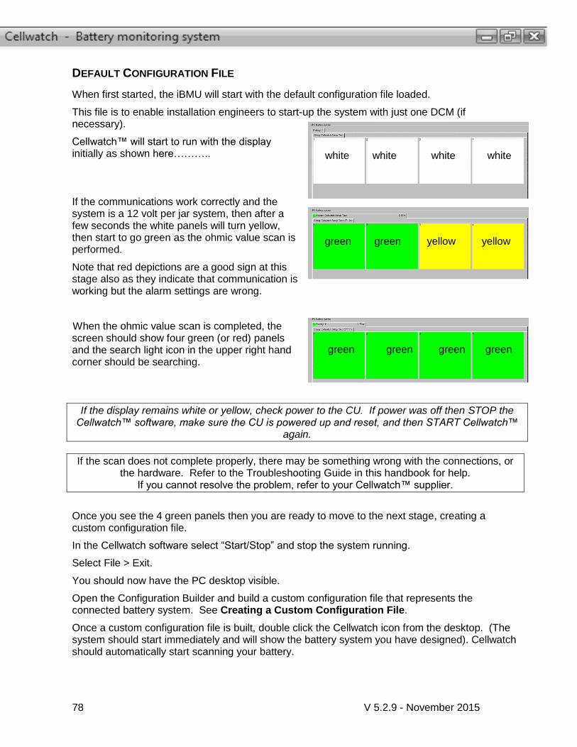
78 V 5.2.9 - November 2015
DEFAULT CONFIGURATION FILE
When first started, the iBMU will start with the default configuration file loaded.
This file is to enable installation engineers to start-up the system with just one DCM (if necessary).
Cellwatch™ will start to run with the display initially as shown here………..
If the communications work correctly and the system is a 12 volt per jar system, then after a few seconds the white panels will turn yellow, then start to go green as the ohmic value scan is performed.
Note that red depictions are a good sign at this stage also as they indicate that communication is working but the alarm settings are wrong.
When the ohmic value scan is completed, the screen should show four green (or red) panels and the search light icon in the upper right hand corner should be searching.
If the display remains white or yellow, check power to the CU. If power was off then STOP the Cellwatch™ software, make sure the CU is powered up and reset, and then START Cellwatch™
again.
If the scan does not complete properly, there may be something wrong with the connections, or the hardware. Refer to the Troubleshooting Guide in this handbook for help.
If you cannot resolve the problem, refer to your Cellwatch™ supplier.
Once you see the 4 green panels then you are ready to move to the next stage, creating a custom configuration file.
In the Cellwatch software select “Start/Stop” and stop the system running.
Select File > Exit.
You should now have the PC desktop visible.
Open the Configuration Builder and build a custom configuration file that represents the connected battery system. See Creating a Custom Configuration File.
Once a custom configuration file is built, double click the Cellwatch icon from the desktop. (The system should start immediately and will show the battery system you have designed). Cellwatch should automatically start scanning your battery.
green green yellow yellow
white white white white
green green green green

79
All that now remains to be done is to check out the system to ensure that all connections are correct and all is well with battery.
NOTE: The Test configuration file will not give a true representation of your battery system, it merely confirms that some hardware is connected and working. You will have
to create a Configuration File for your particular setup.
CREATING A CUSTOM CONFIGURATION FILE
The Cellwatch Config File Builder is used to produce the required Configuration File specific to your monitoring system. There is a full description of the program and how to use it in the Config File Builder Section below and it has a built-in ‘Wizard’ to guide you through the process of generating the file.
You can choose to review the Configuration Builder Manual, or double-click the Cellwatch Config File Builder Shortcut and use the ‘Wizard’. Follow the instructions closely. The format is very informative in order to answer any questions you may have.

80 V 5.2.9 - November 2015
INSTALLATION: CONFIGURATION BUILDER
THE NEED AND THE FUNCTION.
The Cellwatch software application drives a Cellwatch battery monitoring system to continuously monitor your batteries. In addition it provides a graphical representation of your battery on screen either locally or remotely. That graphical representation is converted from a series of hardware addresses that Cellwatch generates for all the hardware components by a configuration file. This configuration file is unique to your battery set-up and is most often generated at the system start-up phase of the installation.
In order to standardize the process of producing a configuration file, the configuration file builder has been developed and is described in detail in this section.
The builder is designed to be used in a number of different circumstances and by differing skill levels of personnel. It is designed to be used in the following circumstances:-
o When the Cellwatch system is being installed for the first time.
o If the system is being reconfigured on site due to battery expansion or some other change.
o A different battery representation of the same battery system is required.
This tool was developed for all skill levels and provides a simple wizard that walks users through building a proper configuration file. A glossary of terms follows to assist the battery technicians to familiarize themselves with what is considered the most commonly used terminology that will be found throughout this description and in the product itself.
The Builder part of the application can be used by personnel familiar with Batteries and Cellwatch and its concepts. The Wizard should be used by all others and first time users. The Wizard will allow most aspects of Cellwatch’s flexibility and functionality to be used. In particular personnel will be able to easily configure duplicate strings and batteries and split or divided strings.
The Builder will allow all the functionality of the Wizard but in addition will allow the skilled user to create null channels.

81
GLOSSARY OF TERMS
Battery:-
A number of cells arranged into a DC electrical storage system. Usually this will consist of a number of strings of cells or jars arranged in parallel.
String:- A sub division of a battery. Often a battery will consist of several strings of series connected cells or jars. These strings are arranged in parallel.
Jar:- American term for a multiple cell container. An automobile battery is a jar containing 6 cells.
Monobloc:- European term for a multiple cell container. A car battery is a monobloc containing 6 cells.
Cell:- The basic unit of a battery, in UPS applications it is traditionally lead acid or calcium acid construction and delivers 2 volts DC (nominal)
UPM or UPS:-
Uninterruptible Power Supply. An electronic device constructed to store electrical energy when mains power is available and deliver power to mission critical loads when mains power is no longer available, for instance during a localized power failure.
System The configuration of batteries on the Cellwatch Battery Monitoring System.

82 V 5.2.9 - November 2015
RUNNING THE PROGRAM
If you are running the program from the iBMU, then it will have an icon on the desktop of the computer and double clicking this should start the program. It is best to ensure that the Cellwatch program itself is not running at this time.
The program is also located in C:\Program Files\Cellwatch and is called configbuilder.exe.
When the program is run, two applications are started. First of all the Builder is started and in the background, to the right of the screen the Wizard is also started. Advanced users can use the background application, but it is highly recommended that everyone use the Wizard. The Wizard can be closed by clicking the ‘X’ on the top right hand corner.
The Wizard is located on the right hand side of the screen so that the battery hardware tree structure in the Builder can be seen growing as the Wizard’s questions are answered.
OPERATING THE SOFTWARE
The objective of the program is to create a file called batconfig.cfg which will reside in the C:\Program Files\Cellwatch folder on the BMU hard disk drive.
This is achieved through a multi stage process starting in the use of either the Builder or the Wizard in the Configuration Builder software. Whichever starting point is used a second stage of review is allowed before the final file is created. This stage allows review of the data entered and either the ability to go backwards and edit that data in the Builder or Wizard part of the program
The Builder. The Wizard.

83
or the ability to edit it on screen there and then. The last phase is the ability to choose a file name (default is batconfig.cfg) and to save the configuration.
The whole process looks something like:-
Chart 1: The Builder process flow.
CONFIGURATION WIZARD
The Configuration Wizard allows someone with the minimum of Cellwatch experience to configure a complex configuration into a Cellwatch system. A complex configuration could include:-
o Multiple batteries with multiple and differing strings
o Multiple strings of differing jar types and hence different alarm limits
o Strings split physically into sub-strings
o Generator cells or strings monitored in addition to UPS configuration
Hence the capability is very broad but the objective of simplicity and accessibility for the infrequent user is also met. This challenge is met by the use of text based screens where a question is asked, multiple layers of extra help offered and then one or two data boxes are presented per screen for completion.
Depending upon answers to previous screens, new questions are asked in order to build up the entire battery topology. The amount of data requested is kept to a minimum per screen and the opportunity is always presented to go backwards using a ‘Go Back’ button. In addition, buttons are provided to allow movement onto the next screen and cancellation of the entire Wizard.
Configuartion WizardConfiguartion Wizard
Configuartion BuilderConfiguartion Builder
Configuartion Review
& Edit
Configuartion Review
& EditName and Save
Name and Save
Start the creation process
here or here.
Complete & exit

84 V 5.2.9 - November 2015
As data is entered, entries are also tested to see if they make sense. Where the novice user may click through a screen that, perhaps, disables the discharge current detection, the program asks “Are you sure?” to ensure the user is certain that this is what they really want to do.
Frequently the ‘Go Back’ button will not go to the immediately prior screen but will go to the start of that phase of the Wizard’s questions.
The overall flow of the software is described below in the Flow-Chart. The opportunity to print out the configuration at both a battery level (describing the battery you have just defined) or at a system level (describing the entire Cellwatch system) is made available at the end of the Wizard.
The Question Further information, tips and advice. Further information, tips and advice.
Further information, tips and advice. Data entry boxes

85
Chart 2: The Wizard screen flow.
If at any time the Wizard is closed and a configuration file has been partly or fully completed but the Builder has not been closed, then the Wizard can be re-invoked and used to review or modify the configuration file. This is particularly useful where a review of the file indicates an error (perhaps as simple as spelling a battery label) and the user is comfortable with the use of the Wizard to modify it.
To invoke the Wizard from inside the Builder use the ‘Configure’ drop down menu and select ‘Wizard’.
How Many
Batteries?
Start
What is This?
Name of
Battery?
How Many
Strings?
Name of
String?
Does it have
Sub-strings?
Number of
Monitoring
Points?
Number of Sub-
strings?
Yes
Number of Blocks
per Channel?
Number of
Channels in nth
Sub-string?
Number of Blocks
per Channel?
Repeat
until
complete
If multiple batteries,
are they the same?
If multiple strings,
are they the same?
Low Volltage
Alarm setting?
High Voltage
Alarm Setting?
Low Resistance
Alarm Setting?
High Resistance
Alarm Setting?
Discharge
Current Alarm
Setting?
Number of
Temperature
probes?
Temperature
Probe Label?
Low Temperature
Alarm Setting?
High
Temperature
Alarm Setting?
Verify Battery
Details?
Verify System
Details?
Voltage and resistance alarm set-up.
Temperature alarm set-up.
Print?
Print?
If more than one
battery on system.
If more than one
string on system.
Note: These alarm settings are bypassed if the 'Same'
tick box is checked on either string or battery levels.

86 V 5.2.9 - November 2015
SUBSTRINGS IN THE WIZARD
Some systems require the use of ‘sub-strings’ in designing a configuration file. Substrings are utilized particularly in rack based, generator, and 16v configurations. Sometimes the installers will wish to ignore or not measure longer inter-tier connections due to wire length or resistance of the cable. In this case the string is broken into smaller components called sub-strings. All rules built into Cellwatch for nulled channels on a string are imposed on the smaller sub-strings; meaning nulled channels are imposed on the penultimate DCM and null channels start with channel 4.
CONFIGURATION BUILDER (I.E. NON WIZARD MODE)
The Builder part of the software is for the advanced user and gives the user the ability to enter a configuration file quickly without using the Wizard. It also permits the ability to manually set up null channels on DCMs where, for instance, a system is to be installed into a 3 block per tray cabinet system and one channel per DCM will not be used.
When started, the Builder always enters one Battery into the tree window (the large white area under the toolbar). Below this Battery, strings, cells and perhaps other batteries will be added as the tree is built. Clicking on the items in the tree will surround them in a blue area and in so doing will highlight them. Highlighting the battery or string is important because it tells the Builder which items (Current Probe, Temperature Probe, or CU) you want to apply which toolbar functions to.
Drop Down Menus
File
New: allows the user to start a new configuration file.
Exit: exits the program.
Configure
Battery Setup: Useful for configurations that have the same battery configuration for all batteries all strings. It starts a mini-wizard permitting the entry of basic battery and string data, including the ability to have similar configurations on multiple batteries. The mini-wizard sequence is: Configure Battery, Configure String window, Setup Alarms.
Configure String: Useful for modifying strings on a battery or all batteries. This permits the number of monitoring points per string to be set up as well as the number of blocks per channel. Using this window the user can disable the ohmic value function for the whole battery as well as make this configuration apply to all strings on this battery or all batteries.
Alarm Limit: this opens the alarm limit window permitting setting up of battery wide alarm limits or the acceptance of default limits dependent upon block voltages proffered.
Wizard: selecting Wizard invokes the Configuration Wizard method of information entry.

87
Options
Global Alarm Setting: with this function selected (it is selected when checked) all alarm setting on the system will be the same.
Help
This provides online help and version control and support options.
Tool Bar
There are 11 function buttons all with textual assist messages enabled to help the user identify their functions. These buttons are not always enabled dependent upon the state of the file being created. When they are not enabled, they are “grayed out”.
Add a battery
Adds the first or subsequent battery to a system configuration. Click this for as many batteries that you require on the system.
Add a string
Add the first or subsequent string to a battery. Grayed out when no battery has been added, click this for as many strings that you require on a battery.
Add a current clamp
Add a current clamp to a string. Grayed out when no string has been created or has not been selected (highlighted).
Add a temperature probe
Add a temperature probe to a sting. Grayed out when no string has been created or has not been selected (highlighted).
Add a measurement point to a string.
The default number of measurement points on a string is four (i.e. one DCM). Each time this button is pressed a point is added. Grayed out when no string has been created or has not been selected (highlighted).
Delete
Permits the deletion of whatever is highlighted. Grayed out if a category rather than a node is selected stopping the user deleting (for example) all cells by selecting the category ‘cells’.

88 V 5.2.9 - November 2015
Alarms
Sets alarm levels on the selected string or on the entire battery if the Options/Global Alarm Setting function is ticked. This function will check for incomplete data entry and will also offer defaults based on block voltages.
Number of blocks per measurement point.
This permits the user to add the number of blocks per DCM channel so that correct numbering sequences can be generated. For instance if 2 blocks (2v or 6v) are entered per channel, the cell depictions on Cellwatch’s screen would be numbered 1 to 2 for the first one, 3 to 4 for the second and so on.
Set up the string details.
This button opens the configure string window. This permits the number of monitoring points per string to be set up as well as the number of blocks per channel. Using this window the user can disable the ohmic value function for the whole battery as well as make this configuration apply to all strings on this battery or all batteries.
Add a control unit to the configuration
This adds a control unit to the system set up. This is added below the toolbar and if no battery or string is selected by highlighting the item in the tree view, the control unit is not allocated any hardware (DCMs, current probes or temperature probes). If however a battery or string is highlighted in the tree view, when a CU is added, that highlighted hardware will be automatically added to that CU. To add unallocated hardware to a control unit it is then simply a matter of selecting the battery or string and clicking on a control unit that has been added below the toolbar.
Multiple control units are depicted and numbered from left to right. Allocated CUs are shown highlighted in the manner of CU number 3 in the illustration above.
Any unallocated CUs visible below the toolbar will be removed when progress is completed through to the review stage of the configuration creation.

89
Delete a control unit from the configuration
By first selecting a CU depiction beneath the toolbar and then clicking this button on the toolbar, the CU is deleted.
More Options
Whenever an item on the battery is highlighted, the right mouse button can be pressed for more options.
These options are:-
Rename: - This permits the highlighted battery item (battery, string, or cell) to be renamed so that the screen label seen when Cellwatch is run is changed.
Configure Batteries: - This function starts a mini-wizard permitting the entry of basic battery and string data, including the ability to have similar configurations on multiple batteries. The mini-wizard sequence is: - Configure battery window, configure string window, setup alarms.
Configure String(s):- : Clicking on this option opens the configure string window. This permits the number of monitoring points per string to be set up as well as the number of blocks per channel. Using this window the user can disable the ohmic value function for the whole battery as well as make this configuration apply to all strings on this battery or all batteries.
Configure Alarms: - Selecting this function opens the alarm limit window permitting setting up of battery wide alarm limits or the acceptance of default limits dependent upon block voltages proffered.
Add null channel: - A null channel is a DCM channel that is not read and not displayed on a Cellwatch screen. This can be used on short tray solutions where a cabinet system has trays of 3 or less cells, monoblocs or jars. It can also be used to permanently eliminate linked out cells where the entire Cellwatch system is not rewired.
Double clicking
Another way to use the configuration builder is to double (left) click on each battery item as the tree item appears on the white part of the screen. So when the initial battery appears on screen

90 V 5.2.9 - November 2015
after the Builder has been started, double click it. This opens a pop-up box, not previously seen asking how many strings on this battery. Entering the number creates the strings on screen.
Double click on each string opens the string configuration window allowing the user to enter number of current and temperature probes per string as well as number of monitoring points on this or every string. Also ohmic value measurement capabilities can be turned off at this point.
Double clicking the current probe permits the user either to select its presence or its absence whereas double clicking the temperature probe enables the user to select the number of probes for this string.
Double clicking the cell root (the entry with the + or – in a box adjacent to it) will permit the total number of cells to be adjusted, see below.
Double clicking the cell number does nothing.
Split strings, short strings and nulls
Perhaps one of the most useful features of Configuration Builder and the Wizard, are their abilities to handle split strings, short strings and nulls.
A split string is where for any number of reasons an electrically continuous string of batteries is split into sub-strings which it is not practical to span with a DCM. Examples of this are where a string is split onto two racks separated by a walkway. Another may be where cells are mounted in cabinets of 3 jars per tray and each tray is regarded as a sub-string.
A short string is one where the number of cells, jars or mono-blocs is not divisible by four. In order for Cellwatch to handle this some nulled or wasted channels of a DCM has to be created and Configuration Builder always does this in a certain way.

91
Split-Strings
A split string is where a string of perhaps, 192 cells of 2v each are mounted on two rack systems of 96 cells each separated by a walkway. Each rack is fitted with 24 DCMs each measuring 4 channels giving us 96 measurement points. The long inter rack connection is deliberately omitted from the measurements.
This configuration is easily created in the Configuration Wizard by selecting the “Has sub-strings” check box when the Wizard asks for a label for the string. In our example above the box would be ticked and in the next window the number of sub-strings would be entered as 2. The questions that follow will then define each sub-string and the assumption made that they are equal sizes, however the user is given the chance to change the sub-string size at any time.
To create two or more sub-strings in the Configuration Builder, create each sub-string as a complete string. In the case of the example above, create two strings of 96 cells each. Then select both strings and right clicking with the mouse, select “Join Strings”. These strings will be treat as one large string when the configuration file is created.
To connect up the DCMs, simply connect them like any ordinary string.
If the number of cells in the sub-string is not divisible by 4, then the user must treat each sub string as a short string and create a null at the end of the sub-string as described in the section entitles Short Strings, below.
Short Strings and Null Channels
If a string had 30 jars it would require 8 DCMs with 2 channels wasted or nulled. These channels are determined by the Configuration Builder automatically and as a rule always commence with channel four of the next to last (penultimate) DCM. If this channel is not sufficient, channel 3 is nulled out and so on. Channel one is never nulled out. The DCMs are wired up to the battery in the usual manner except for the next to last DCM. The next to last DCM is always wired one or more channel doubled up (see illustration below).

92 V 5.2.9 - November 2015
Ja
r 2
6
-
+
Ja
r 2
5
-
+
Ja
r 2
4
-
+
Ja
r 3
0
-
+
Ja
r 2
0
-
+
Ja
r 2
8
-
+
Ja
r 2
7
-
+
Cellwatch DCM
Module
Cellwatch DCM
Module
For systems with a number of monitoring points not divisible by 4 (see a 30 channel
configuration above) always null DCM channels on the next to last DCM.
NOTE: The DCM (version 2) requires 7 volts to operate. DCM EX requires 3.7 volts to power on, but will not take measurements when the voltage is below 5 volts.
In the example above; the third and fourth channel on the penultimate DCM are read as zero volts and ohms. Therefore channel 3 and 4 of DCM 7 must be nulled out in the software. The nulled channels are only ever read and more importantly, displayed once.
The Configuration Builder does this automatically whenever a short string (not divisible by four) is entered and it will always be the penultimate DCM’s channel four that is nulled.
When the Wizard is used, it obeys the same rules. In addition if a split-string is configured, then the null with occur on the penultimate DCM on both sub-strings. The same rules apply.
Short Tray Solutions.
There is a situation where the above rules do not apply. This is where the Cellwatch system is fitted to a cabinet configuration of trays of less than 4 jars per tray. In a 4 jars per tray system, each tray has one DCM dedicated to it and no special configuration is necessary. However, if there are only 3 jars per tray the installer has only one option; treat each tray as a short sub-
DCM EX A minimum of 3 channels must be utilized when using the short string method on 2 volt jars. Failure to do so will leave the DCM unable to respond to voltage and ohmic readings though the fiber loop will remain active.

93
string of only 3 jars and null/double up channel 4 of each DCM. This can often be the case for 16v jar configurations.
Consider the example of a cabinet of 36 monoblocs or jars of 12v each on 12 trays. In the Configuration Builder the user can easily set up a 36 jar string. If one DCM is employed per tray nulling out channel 4 must be used.
A single channel must be ‘nulled’ on the DCM to make it into a three channel DCM. This is traditionally channel 4 on all versions.
To use this feature set up the correct number of jars or monoblocs as sub-strings (say 12 trays of 3 =36). And Configuration Builder will build it for you automatically.
Then on the last jar per DCM (jar number 3, 6, 9, 12 etc.) tell the Configuration Builder that there is 1 null cell following this one by right clicking on jar 3 and selecting null channel. The Builder will ask how many null channels and in this case the answer will be 1. Repeat this for every third jar and in this way eliminate every fourth DCM channel on every third jar.
To connect this up correctly, follow this procedure:-
1. Tab the three jars as follows: - double tab the most positive post of the tray, single tab all other negative posts and triple tab the most negative post of the tray.
2. Connect the DCM as follows:-
a. Red and Brown to the most (double tabbed) positive post.
b. Blue and White to two of the triple tabbed negative post (it should beep).

94 V 5.2.9 - November 2015
c. Orange to the negative of channel/jar 1.
d. Yellow to the negative of channel/jar 2.
e. Green to the spare tab of the most negative post.
This should result in 0 volts being read by the fourth channel of the Cellwatch system which is nulled out and therefore not visible on the screen.
16V 16V 16V
DCM
+ -
Note: Channel 4 is nulled
Figure 4 Short Tray Solution
This feature can also be useful when a battery string jar or monobloc count is not divisible by four and the user wants to select the null channel to perform an overlap somewhere other than where the Configuration Builder suggests (see the section entitled Overlaps).
The Configuration Wizard does not support the short tray or nulled channel solution automatically.
REVIEW SCREEN
After the system tree has been created, in the initial part of the program using either the Builder or the Wizard, the Next button at the bottom of the program window is made available. This button is grayed out when the building operation is incomplete. Pressing this button closes the builder window and transfers the data generated so far into the review window.
Here the data can be seen in the same format that it can be reviewed inside Cellwatch. In addition it can be edited and saved to disk.
Edit
By selecting Edit/Edit Configuration the main screen window allows editing of the configuration file.
Mouse directed cursor movements, or selection by Shift & arrow movements (or PgUp or PgDn) will select cells in the configuration file. Ctrl-C and Ctrl-V will cut and paste these cells in the usual manner for a Windows spreadsheet type application.

95
In addition data entry into a block of cells will copy the entered data into all cells. Similarly Backspace will delete all the data in a block of selected cells.
Any edits that were performed will be lost if the user returns to the previous Builder screen.
Save
The Save function allows the file to be saved prior to editing. The opportunity to choose a filename is presented and the default is batconfig.cfg.
Selecting Next at the bottom of the review screen automatically asks the user to select a file name and location before completion.
Errors
If impossible configurations are forced into the builder at the build stage (such as too many channels in a control unit) then error screens are presented to the user when entering into the review phase. This permits the user to either remedy the errors at this review stage or return to the Builder to fix them.
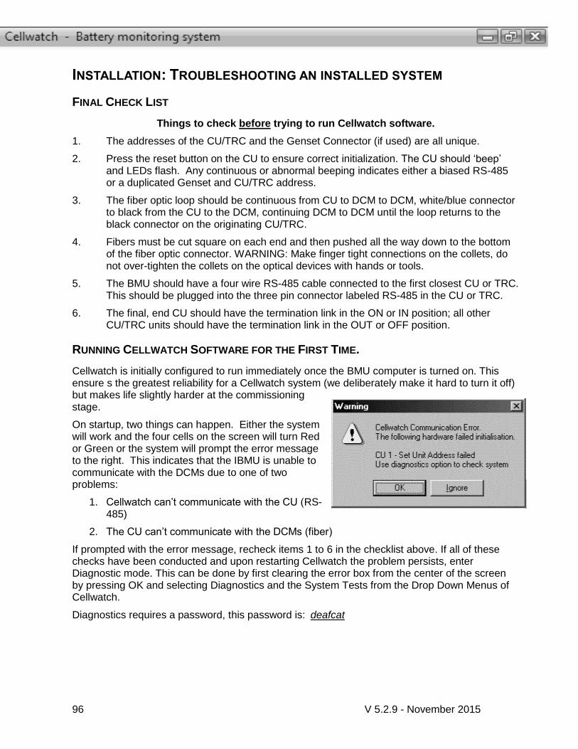
96 V 5.2.9 - November 2015
INSTALLATION: TROUBLESHOOTING AN INSTALLED SYSTEM
FINAL CHECK LIST
Things to check before trying to run Cellwatch software.
1. The addresses of the CU/TRC and the Genset Connector (if used) are all unique.
2. Press the reset button on the CU to ensure correct initialization. The CU should ‘beep’ and LEDs flash. Any continuous or abnormal beeping indicates either a biased RS-485 or a duplicated Genset and CU/TRC address.
3. The fiber optic loop should be continuous from CU to DCM to DCM, white/blue connector to black from the CU to the DCM, continuing DCM to DCM until the loop returns to the black connector on the originating CU/TRC.
4. Fibers must be cut square on each end and then pushed all the way down to the bottom of the fiber optic connector. WARNING: Make finger tight connections on the collets, do not over-tighten the collets on the optical devices with hands or tools.
5. The BMU should have a four wire RS-485 cable connected to the first closest CU or TRC. This should be plugged into the three pin connector labeled RS-485 in the CU or TRC.
6. The final, end CU should have the termination link in the ON or IN position; all other CU/TRC units should have the termination link in the OUT or OFF position.
RUNNING CELLWATCH SOFTWARE FOR THE FIRST TIME.
Cellwatch is initially configured to run immediately once the BMU computer is turned on. This ensure s the greatest reliability for a Cellwatch system (we deliberately make it hard to turn it off) but makes life slightly harder at the commissioning stage.
On startup, two things can happen. Either the system will work and the four cells on the screen will turn Red or Green or the system will prompt the error message to the right. This indicates that the IBMU is unable to communicate with the DCMs due to one of two problems:
1. Cellwatch can’t communicate with the CU (RS-485)
2. The CU can’t communicate with the DCMs (fiber)
If prompted with the error message, recheck items 1 to 6 in the checklist above. If all of these checks have been conducted and upon restarting Cellwatch the problem persists, enter Diagnostic mode. This can be done by first clearing the error box from the center of the screen by pressing OK and selecting Diagnostics and the System Tests from the Drop Down Menus of Cellwatch.
Diagnostics requires a password, this password is: deafcat

97
Once the password has been entered you will be within the diagnostic area of Cellwatch.
You may have from one to thirty one Control Units and/or Thermal Runaway Controllers on your system. The diagnostic function allows you to talk to each controller individually. So, to test the proper operation of each CU it is a simple matter of selecting the first CU (always number one), using the selector on the left of the window and send it an ILA followed by a SUA.
The ILA will initialize the unit and SUA will send it a software address. The return message should be an accurate count of the number of DCMs on that CU’s network loop.
If the first unit is satisfactory, increment the CU number and try again with unit number 2 (assuming you have more than one CU on the system). Continue until you find the CU where the fault lies. This is indicated by an ‘error no loop back’ in the status box.
COMMON FAULTS
The majority of faults on a new installation are due to mis-wired RS-485 communications cable or improper termination jumpers. For existing installations the most common problem tends to be breaks in the Fiber Optic loop due to battery maintenance or loose fiber connections that were not secured.
Termination jumpers should be verified that they are configured correctly. All termination jumpers on the CU/TRC should be configured in the OUT or OFF position until the last CU/TRC on the RS-485 communications bus. Each CU should also have unique addresses that should not be repeated.
Fiber optic issues could be caused by unpowered DCMs or improperly installed fiber optics (black to black and white/blue to white/blue instead of white/blue to black).
Temperature Probes are Incorrect
Temperature probes may read 0C/32F or 80C/180F if a temperature probe connection is mis-wired or has become disconnected. Check the termination connectors at the CU/TRC for a secure connection. Ensure that the molar connector contacts bite the wire and not the insulation which can cause for a poor electrical connection.
Current Readings are Positive in a Discharge File
Current readings will show positive during a discharge file if one or more CTs are installed improperly. If all CTs are connected improperly then Cellwatch may not detect a discharge at all. Check the orientation of the CT and ensure that it follows the T.I.N.A.P. installation method and that the wires are correct in the Control Unit.

98 V 5.2.9 - November 2015
NAVIGATING DIAGNOSTICS
Immediately you will notice several numbers on the bottom left of the screen highlighted in four boxes. These numbers ‘1101’ are an address reference that correlates to the configuration file settings as shown below.
The PT, CU, DCM, and CH columns as identified above correlate to the Port, Control Unit, Cellwatch Unit, and Channel labels in diagnostics. Port references the COM port that Cellwatch will use to communicate to the CU or TRC units, typically this will be ‘1’ on all IBMU units. Control Unit will reference the CU or TRC address set on each unit, typically this will be units ‘1’ to ‘31’. Modifying Cellwatch Unit will adjust the unit on the fiber loop that is being polled. A unit of ‘0’ references the Control Unit, or fiber optic unit zero. Units ‘1’ to ‘254’ reference the DCM units on the fiber loop. Channel references the data channel on a DCM or CU, typically ‘1’ to ‘4’.
ERROR: NO LOOP BACK
If the CU or TRC does not respond satisfactorily to the ILA and SUA test. The Diagnostic Status message will be received as shown in the illustration, following the SUA.
If this occurs it is recommended that the diagnostic flow chart be followed in detail at the end of this guide. In that flowchart, references are used to refer to paragraphs in this guide for detail actions.
1. Ensure you are addressing the correct CU/TRC identified in diagnostics by the ‘Control Unit’ address number.
2. If the CU/TRC does respond with an error to the ILA and SUA, reset the CU/TRC and ensure that you hear the ‘beeper’ sound. If there is no sound and the LEDs are not lit, look for power (or absence of power) on the CU/TRC power inlet connector.
3. If the power is applied to the unit and LEDs are ON but the unit still does not reset, remove all other connectors from the unit and try again. In this way a faulty or misplaced connection can be eliminated.
4. If the unit resets but the ILA and SUA returns a message stating ‘Error, no loop back’ then there may be a problem on the fiber-optic loop or RS-485. Press the DIA (Test RS-485) button at the bottom of diagnostics. One of two responses will appear: ‘Fault in RS-485’ or ‘RS-485 OK’.
5. If RS-485 is OK the problem is likely the fiber loop. You can test the transmit and receive abilities of the CU/TRC by fitting a short piece of fiber optic cable between the white/blue

99
and black connector on the suspect CU/TRC and pressing SUA. If this clears up the fault (it will return the message ‘0 units on this loop’) then the problem lies with the DCM loop. If the fault persists, then there is a problem with the CU/TRC. If the problem is with the CU/TRC please contact Technical Support for further assistance.
6. To eliminate the CU/TRC being the problem, press RVD or XTR while the settings on the left of the diagnostic window point at a particular CU/TRC. If data is returned into the Current and Temperature windows on the bottom right of the diagnostic window, then the CU is communicating and responding correctly. This would confirm the problem lies with the DCM loop. Note if the current and temperature probes are fitted, then this should be ‘good’ data, if you still have connectors out the data will be zeroes. Either indicate proper communication with the CU/TRC.
A FAULTY DCM LOOP
There are two possible things that can go wrong with a DCM loop. There can be a problem with the fiber optic network or there can be a problem with one of the DCMs on the loop. However, if all DCMs were monitored for correct ‘beep’ when installed, it is very unlikely that a DCM will be faulty and the cause of the problem.
If the CU investigation indicates that the DCM loop is faulty then it is necessary to identify where on the loop the fault lies. This is easy with Cellwatch.
There are three ways to do this. The best and safest way is given below.
The diagnostic window has a function at the bottom of the buttons called TFO (Test Fiber Optic). Pressing this button will lock diagnostics into the TFO mode until the button is pressed again. The command will send pulses of light around the fiber loop. Each DCM that receives the pulse will beep and pass the signal on. By breaking the loop half way around the loop and looking into the outlet of a white fiber optic transmitter check for a red light pulse in synchronization with the DCM beeps (approximately one pulse every second).
By halving the halves and halving again, in very few moves an entire fiber-optic network can be diagnosed this way. An example is shown below:
Example: A 128 DCM loop has a problem with the fiber in DCM 67.
Start the TFO function running by pressing the TFO button on the diagnostic window.
Step 1. Half the loop at DCM 64 and check for light output. Result OK. This confirms that the DCMs between DCM 1 and DCM 64 is OK.
Step 2. The faulty loop is now between DCM65 to 128. Look for light output halfway between the two, DCM 96. Result faulty.
Step 3. The faulty loop is between DCM 65 and 96. Look for light output halfway between the two, DCM 80. Result faulty.
Step 4. The faulty loop is between DCM 65 and 80. Look for light output halfway between the two, DCM 72. Result faulty.
Step 5. The faulty loop is between DCM 65 and 72. Look for light output halfway between the two, DCM 68. Result faulty.
Step 6. The faulty loop is between DCM 65 and 68. Look for light output halfway between the two, DCM 66. Result OK.

100 V 5.2.9 - November 2015
Step 7. The faulty loop is between DCM 67 and 68. Look for light output halfway between the two, DCM 67. Result faulty. The problem must be DCM 67!
Turn off the TFO function by again pressing the TFO button.
Once the DCM or fiber segment is isolated, the installer can now determine the problem with the DCM. Very rarely, it could be the DCM itself or most likely the fiber optic network connection. If the DCM is suspected, please see the How to Verify a DCM in the section below. The fiber connection to the DCM may not be seated properly. Loosen the collet and reseat the fiber all the way home, if necessary recut the fiber to ensure a square, 90 degree angle. If the fiber is seated correctly, the DCM may be faulty or misconnected. When the DCM is correctly connected to the battery it should emit an audible beep. Misconnecting the DCM will not (in normal circumstances) cause any damage to the DCM and it may be disconnected and the re-connected correctly. If the DCM is connected correctly and fails to emit an audible sound and the LEDs on the DCM do not flash then the device may be faulty.
NOTE: The above loop diagnostic method can also be performed using a flashlight shone into the black optical ports on DCMs while a colleague watches the Red LED behind the Receive optical port (the black one) on the CU. This red LED will mimic the flashlight illumination if the loop is working.
Alternately, the ALB function can be used to sound the DCM sounder and flash the DCM LEDs successively around the loop to aid in fault location.
HOW TO VERIFY A DCM
In some cases a DCM may be suspected of being faulty or may need to be verified for proper operation or calibration. In cases where the DCM is suspected to be at fault it is recommended to swap the DCM with a known working module, i.e. not a new module whose operational state is not known. Stop Cellwatch, remove the suspect DCM and swap it with one next to it. Once reconnected, restart Cellwatch and begin scanning again. Once the scan has finished review the results to see if the problem has followed the DCM. If the DCM is determined to be faulty it should be replaced. It is recommended that NDSL Technical Support be notified a unit has failed, even if out of warranty.
WHAT HAPPENS IF THERE ARE CROSSED WIRES FROM A DCM
There are two possible scenarios relating to crossed wires; one where the internal wires are crossed (orange, yellow or green) and one where the end wires (blue/white or red/brown) are crossed.
Symptom 1
When first run, the display has a one or a few red cells appearing after the initial voltage scan. On closer inspection one cell voltage is double the normal voltage for the measurement point and the adjacent voltage is zero, or even negative.
Problem
A pair of wires leaving the DCM have been swapped over. For example the orange and yellow wires have been put in each other’s place on the battery.
Solution
Check the cable order related to color (not exit order from the DCM) and return to the correct order.

101
Symptom 2
When first run one or several red cells appear on the string display. Closer investigation shows these to be either zero or very low ohmic value while all other ohmic value readings are normal. In some cases the associated voltage reading is also zero.
Problem
Either the white, blue, red or brown cable has been crossed over and connected to the opposite end of the cell it should be monitoring. The resulting scenarios are described in the following four illustrations:-
Solution
From the illustrations determine which possible situation applies and correct accordingly.
Crossed Wires show near zero readings for some cells
Re
d
Bro
wn
Gre
en White
blu
e
Ora
ng
e
Ye
llow
+
White wire crossed, one cell,
cell 4 has NO voltage and NO internal
resistance.
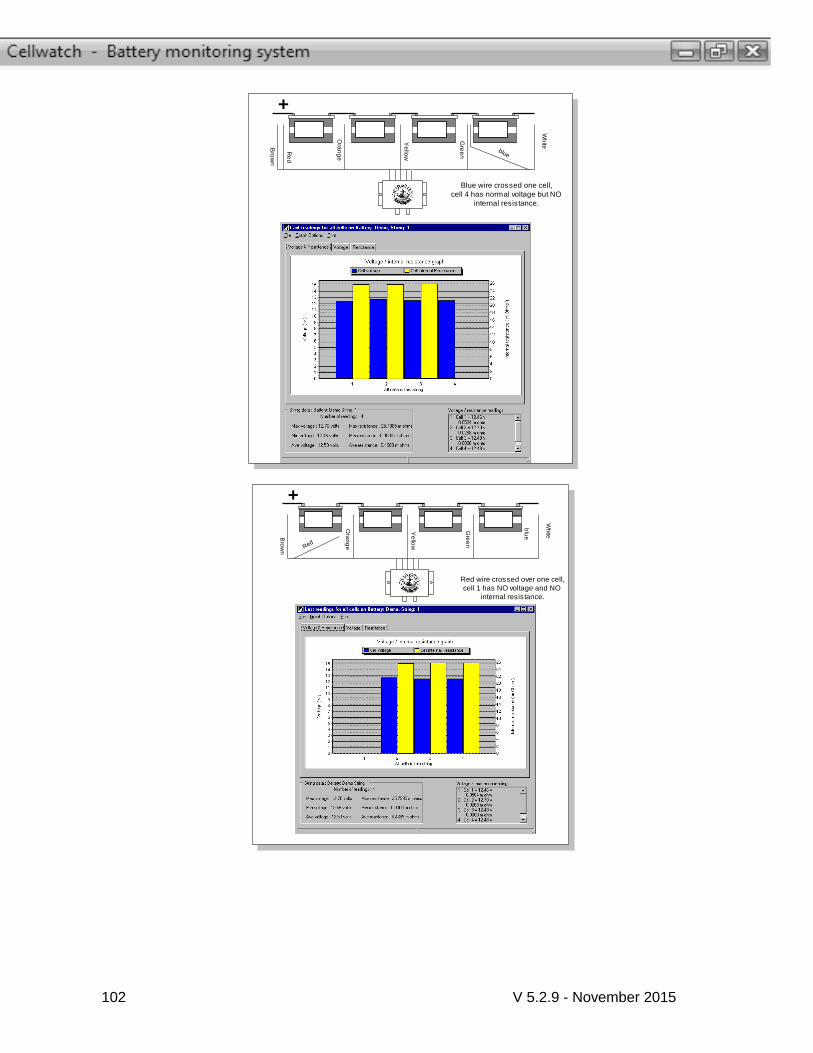
102 V 5.2.9 - November 2015
Re
d
Bro
wn
Gre
en
Wh
ite
blue
Ora
ng
e
Ye
llow
+
Blue wire crossed one cell,
cell 4 has normal voltage but NO
internal resistance.
Red wire crossed over one cell,
cell 1 has NO voltage and NO
internal resistance.
Red
Bro
wn
Gre
en
Wh
ite
blu
e
Ora
ng
e
Ye
llow
+
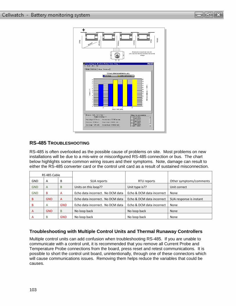
103
RS-485 TROUBLESHOOTING
RS-485 is often overlooked as the possible cause of problems on site. Most problems on new installations will be due to a mis-wire or misconfigured RS-485 connection or bus. The chart below highlights some common wiring issues and their symptoms. Note, damage can result to either the RS-485 converter card or the control unit card as a result of sustained misconnection.
RS 485 Cable
SUA reports RTU reports Other symptoms/comments GND A B
GND A B Units on this loop?? Unit type is?? Unit correct
GND B A Echo data incorrect. No DCM data Echo & DCM data incorrect None
B GND A Echo data incorrect. No DCM data Echo & DCM data incorrect SUA response is instant
B A GND Echo data incorrect. No DCM data Echo & DCM data incorrect None
A GND B No loop back No loop back None
A B GND No loop back No loop back None
Troubleshooting with Multiple Control Units and Thermal Runaway Controllers
Multiple control units can add confusion when troubleshooting RS-485. If you are unable to communicate with a control unit, it is recommended that you remove all Current Probe and Temperature Probe connections from the board, press reset and retest communications. It is possible to short the control unit board, unintentionally, through one of these connectors which will cause communications issues. Removing them helps reduce the variables that could be causes.
Re
d
Brown
Gre
en
Wh
ite
blu
e
Ora
ng
e
Ye
llow
+
Brown wire crossed over one cell,
cell 1 has NO internal resistance but normal
voltage.

104 V 5.2.9 - November 2015
Often times the problem is due to a RS-485 connection between CUs. If removing the CT and TP connectors does not work, it is then recommended to isolate each control unit and introduce them to the RS-485 bus one at a time. Starting with only CU 1 on the RS-485 bus, adjust the termination jumper and press reset. Test communications with CU 1. Once successful communications have been established, introduce the second CU. Again, adjust termination jumpers as necessary. Once communications with CU 2 are established, introduce CU 3; and so on… If there are still issues and you believe the card is at fault, please contact NDSL Technical Support for further assistance.

105
FAULT FINDING FLOW CHART
Press reset on CU
(see 3.1.1.)
Check voltage
switch is correct
(see 3.1.2.)
Correct
Check
for electrical
damage including
fuse
Silence
Incorrect
Loop out the DCMs
(see 3.1.3.)
Perform
ILA & SUA from
diagnostic area (see
3.1.3.)
Damaged
Check
DCM loop with
flashlight
(see 3.2.2)
Good
CU works OK
Bad
Good
'Beep'
Good data returned
Still
doesn't
work
Check
CU is good by
pressing RVD in
diagnostic area.
(see 3.1.4)
No dataRemove all CTCT and
TP leads. Check again.
First time,
so re-try
Still no data
Reconnect
DCMs to CU and try
again, ensure fibers
'seated'
Problem
resolved
Message returned 'Error no loop back'.
Seek help
and advice
Fault Find DCMs
(see 3.2.1.)
Problem
resolved
No DCM fault found

106 V 5.2.9 - November 2015
FINAL POST TROUBLESHOOTING CHECKLIST
1. Ensure that Cellwatch scans automatically on start-up. To do this select from the Drop Down Menus; Scan Control / Scan Settings and tick the box indicated in the illustration on the right.
2. Ensure that the alarm levels are set correctly. See Alarm Levels in the Cellwatch Software Manual.
3. Check the currents and temperatures on all Current Probes and Temperature Probes are reasonable. This can be done by hovering the cursor over the string tab or panel and reading off the temperatures and currents. It is not unusual for the currents to fluctuate rapidly due to electrical noise and ripple current. Dependent upon the size of UPS this
should be in the range of 5 amps (smaller or larger if current scaling is utilized). Ensure the current alarm level is well beyond this ripple value but inside the predicted discharge current.
4. Ensure all cell depictions are enlarged in the string panels and all cells and tabs are green.
TIP - Continuous Buzzer.
The Control Unit buzzer will sound continuously for one of two reasons:-
1. There is a fault in the RS485 wiring, check the chart below.
2. The termination link on the CU board is in the OUT position when it should be IN.

107
INSTALLATION: MAINTENANCE
Although the Cellwatch system will not need servicing, the battery may, and NDSL recommends that safety procedures and safe working practices as described in the appropriate battery maintenance manual, be followed closely.
VERY IMPORTANT
When it is recommended that battery links or inter-cell connection be removed for safe working, it is important to totally remove any Cellwatch DCM which is connected across any broken link. If a battery link is removed anywhere on the battery the risk is present of abnormally high voltages. This high voltage can damage the Cellwatch Data Collection Module. Alternatively if input measurement voltages are applied with a powered DCM, damage may occur to the input voltage sensors.
This unit must be disconnected prior to separation and subsequent removal of the link. (Please note each unit in this system spans many mono-blocs)
Particular attention must be paid if a link between two levels or tiers of batteries on the racking system is to be broken as a Cellwatch unit may span the two end cells /mono-blocs.
After servicing the battery, any removed links must be fitted and reconnected before the
Cellwatch modules are reconnected. Failure to do this may result in the Cellwatch module being damaged.
Always check the Cellwatch system after such servicing.
BATTERY STORAGE, CARE AND MAINTENANCE
The following information is supplied with permission of Yuasa Battery Sales (UK) Limited as an example. Always follow manufacturer recommendations for the batteries specified at your installation.
The storage or shelf life of a battery is usually between 12 to 18 months at 20 oC starting from a charged condition.
WARNING - Never store in a discharged or partially discharged state.
Always store in a dry, clean, cool environment in the original packing.
If storage of 12 months or longer is envisaged, supplementary charging will be required.
DESIGN LIFE
Float: Each battery type will have a prescribed float design life. Please be aware of this life expectancy and replace the battery as end-of-life approaches. Keep a reference or label the battery to show its date of installation, as this will indicate replacement at the right time.
Cyclic: Each battery suited to cyclic use will have a prescribed quantity of cycles to end of life and is dependent on depth of discharge. The depth of discharge is expressed as a percentage of the capacity required per duty cycle.

108 V 5.2.9 - November 2015
Near the end-of-life the standby capacity of the battery will reduce. When this reduction becomes regular, this indicates time for replacement.
BATTERY CARE
To ensure optimum battery performance and life, it helps to take care of your battery by observing the following:-
WARNING - Never leave a battery in a discharged state.
If a battery has an open-circuit voltage lower than its rated value, then sulfation may well be the cause.
When a battery is left in a discharged state or for prolonged periods of storage lead sulfate crystals begin to form acting as a barrier to recharge and will prevent normal battery operation.
Depending on the degree of sulfation, a battery may be recovered from this condition by constant current charging at a higher voltage with the current limited to one tenth of the battery capacity for a maximum of 12 hours.
Note the applied voltage will exceed the normal recommendation and so the battery must be monitored (not left unattended) and removed from charge if excess heat is dissipated. The voltage required to "force" this maximum current into the battery will reduce as the battery recovers until normal charging can take place.
In extreme circumstances a battery may never fully recover from sulfation and must therefore be replaced.
BATTERY SAFETY
Batteries are electrically live at all times, take great care never to short-circuit the battery terminals. High DC voltages, are more dangerous than the mains.
Batteries are often heavy, take care when lifting and transporting batteries. For weights above 24 kilos or 50 pounds, lifting aids should be used.
Do not attempt to remove the battery lid or tamper with the battery internal workings. VRLA Batteries are "low-maintenance" requiring no electrolyte top-up or measurement of Specific Gravity.
Finally, when a battery has reached the end-of-life it must be returned to the point of sale or to a licensed battery dealer for recycling. Please observe the following points.
Do not throw batteries in a bin at their end-of-life. VRLA batteries contain substances harmful to the environment so return to your supplier for disposal. Never bury in the ground or incinerate at end-of-life. Batteries contain harmful substances making this unsafe.
Return the spent battery to a recycling center or licensed battery dealer for re-cycling.

109
INSTALLATION: ABBREVIATIONS AND DEFINITIONS
Ah Ampere hour- The unit of battery capacity
Battery One or more cells, mono-blocs or jars
iBMU Integrated Battery Monitoring Unit
Battery String A number of mono-blocs connected in series
Bloc Abbreviation of mono-bloc or jar
Cell The smallest battery multiple i.e. for lead acid this is 2V
CU Control Unit
Cyclic Continuous charge/discharge cycle often used in traction applications
DC Direct Current - as produced by a battery
DCM Data Collection Module
Discharge Current flow OUT of the battery
Float Continuous charging for use in emergency or back-up applications
Jar Multiple cell unit in one container
Mono-bloc A multi-celled single bloc or jar
Ni-Cad Abbreviation for Nickel-Cadmium, a type of rechargeable battery
PC Personal Computer, one option for connecting to an iBMU.
RS 485 A communication protocol
TRC Thermal Runaway Controller
VRLA Valve Regulated Lead Acid (a type of battery)
-ve end of battery The point of least potential in the battery string
+ve end of battery The point of highest potential in the battery string


V4
SOFTWARE


V4
SOFTWARE: INTRODUCTION
The design aim of Cellwatch is that it should be THE Battery Monitoring system that is easy to install and operate. The Cellwatch software is released for Windows XP and Windows 7 Embedded iBMUs. Newer versions are only supported on the latest operating system.
The software is designed to be easy to use and intuitive. It has undergone years of testing both inside our laboratories and in the field. If the software does not perform as you expect, we want to hear from you. Contact us by telephone or email and provide your honest feedback. It may be that your request can be accommodated and we will try to help you immediately. Alternatively we will always listen to your objectives and try to incorporate your requirements as soon as possible into future releases of the product. Contact details are at the end of this section.
This manual is organized in such a way as to guide you through all the essential features of the software and will explain everything. In addition, towards the end of this book, you will find guides on how to carry out the most common objectives of your system.
Contact your Cellwatch supplier:
…or contact NDSL, makers of Cellwatch direct:
United Kingdom
By Phone +44 (0)1865-884288 By Fax +44 (0)1865-884289 By E-mail [email protected]
United States of America & Canada.
By Phone +1-919-790-7877 By Fax +1-775-535-0139 By E-mail [email protected]
Asia
By Phone +86 21-61138828 By Fax +86 21-61138838 By E-mail [email protected]
Cellwatch Partner/Reseller: Please provide contact information for the end-user here: Company Name: ___________________________________________ Company Phone: ___________________________________________

114 V 5.2.9 - November 2015
SOFTWARE: OVERVIEW
WHAT THIS SOFTWARE WILL DO FOR YOU
What Cellwatch monitors
This software runs as an executable application on the Integrated Battery Monitoring Unit (iBMU) running Windows 7™ operating system.
Through the iBMU’s dedicated RS-485 serial port (s) the software will act as a system driver for Control Units (CU) or Thermal Runaway Controllers (TRC) attached to the iBMU. In addition it acts as a system driver to all the Data Collection Modules (DCMs) attached to each CU/TRC.
Internal to the iBMU, the software creates and updates database files to store data for retrieval from the computer’s hard disk drive. These logs can be accessed either through the Cellwatch software or through third party systems to present data reflecting performance, condition or history of the battery under scrutiny.
Finally, the software acts under user programmed control on the data it gathers and has the ability to operate a number of alarm outputs provided in the CU(s)/TRC(s) connected to the system.
The software cannot monitor parts of the battery to which it’s CU(s)/TRC(s) or DCMs are not connected. In addition it cannot represent a level of detail that is beyond the battery architecture to reveal. For example, Cellwatch cannot indicate which cell of a 6-cell jar or monobloc is faulty if there are no inter-cell connections made to the Cellwatch Battery Monitoring system.
In addition the system does not affect directly how charge is applied to offline or standby, float charged batteries. Information on connecting to building management systems can be obtained by contacting technical support.
How often
Voltage data can be read at a frequency determined by the user of the system (constant, hourly, every 6 hours). All readings taken during a day are stored and then rolled up into an average at midnight every day. Similarly ohmic value scan frequency can be determined by the users of the system (once or twice daily).
The frequency at which results are logged is pre-set by the user, under the software’s Scan control/Set up scan frequency function of the drop down menu. Instructions will be covered later in this guide.
The system allows you a high degree of flexibility but does not allow the user to collect unnecessary detail that would result in wasteful or excessive usage of data storage. For this reason the voltage measurement can be made and recorded more frequently than the ohmic value reading.
What output files it generates
The system software creates several output files that are covered more fully later in this handbook.
Upon system set-up it utilizes a configuration file (.cfg) in which all of the architectural information about the system, its components and the interconnection of cells, strings and batteries are stored. It is unlikely that this file will ever need to be accessed except in the event of a problem when a Cellwatch service center may wish to access this file.

V4
A History file (.his) is created that stores data for an entire year. The file is created on the BMU hard drive and is named after the year in which the file is set-up. A new file is created at the beginning of every year.
A Discharge file (.dis) is created every time the battery system switches into a discharge (as detected by the current measuring device installed on the string). This file contains voltage data collected continuously for the period of the discharge.
All .cfg, .dis, and .his files are stored in Comma Separated Values format, or CSV which can be imported into excel or other databases.
Log files (.log) are created in text format to allow the user or technician to see what happened in the system. These can be very valuable for diagnosis of events and problems.
What should I do with the data?
Conventional battery monitoring methods dictate that technicians visit the site to carry out cell measurement and recording operations once every three months or as frequently as six weeks. Automatic electronic monitoring gives us the opportunity to collect much more detailed data. All of this will be wasted if the data is not used, interpreted and acted on.
It is recommended that all users of the Battery Monitoring system develop a plan for monitoring, review and storage of all battery data as well as an action plan to determine what action should take place if the Battery Monitoring system indicates cell or battery failure.
A single sheet guide is enclosed with all systems but extra copies may be requested or downloaded from the Cellwatch website at www.cellwatch.com.
Who to contact for Additional Assistance?
We want every customer to know how to understand and interpret battery data. Following the installation, the installer of the system should spend time with the end-customer to familiarize the customer with the Cellwatch Battery Monitoring System. Upon request, and for a fee, NDSL will conduct End-User training sessions, at the customer location of choice. We want to be sure that customers know as much as possible about their Cellwatch System and how to get the most out of both Cellwatch and more importantly, their battery.

116 V 5.2.9 - November 2015
SOFTWARE: USING THE SOFTWARE
INTRODUCTION TO USING WINDOWS APPLICATIONS.
When the Cellwatch application program is running with the system operational and active, the screen will look something like the image shown above.
Cellwatch software’s main window is a typical Windows™ application screen and has many areas in common with all other similar Windows™ programs. This screen can be split into three areas: The Blue Title Bar, the Drop Down Menus and the Application area, which is the largest part of the screen. The Application area is further subdivided and is explained later in this section.
The Blue Title Bar displays the title of the software and contains several controls. In addition, it can be used to move the application window when it is in restore mode by dragging and dropping the blue bar.
Try exploring the four controls, first click on the icon in the top left hand corner of the screen. This is the ‘System Menu’ icon and enables you to manipulate the window of the program in a manner common with all other Windows™ applications.
The three controls at the top right hand corner reading from left to right are the application controls enabling you to Minimize, Restore (or Maximize) and Close the application. These all
operate in the same manner as most other Windows applications. Hence their detailed usage will not be covered here.

V4
THE CONTROLS, BASIC DESCRIPTION (FOR USERS NEW TO WINDOWS).
The Drop Down Menus, Basics.
Drop Down menus are used throughout this software to give access to system functions. They are accessed by hovering over the word that best indicates the function you want to access (see illustration above and detailed description below).
To activate the drop down menu, simply hover over the menu and left click. As indicated below, the selected drop down menu will highlight with a light box.
Scan control - has been selected
Clicking momentarily down on the left mouse button and then releasing will drop down a menu below the word you have chosen, but only as long as the pointing device is over the word, in this case Scan control. This menu will reveal a number of further sub-options.
These sub-options appear below the menu header as a series of choices. Without clicking the mouse buttons any further but by gently scrolling the pointing device down the choices, each will be highlighted in a color different from the background.
When the desired choice has been selected, the left mouse button is clicked and released, once only and that function is invoked.
If the selection made is not the correct one, it can be reversed by either: -
Pressing Esc on the keyboard in the event that it is a Windows pop-up box asking for a data file input or similar.
By pressing Cancel, or the crossed box in the top right hand corner, if it is a Cellwatch data or input box.
By pressing a second time, if it is a tick or check mark enabled action. This will remove the tick (check) mark, indicating its de-selection.
By pressing OK if the Windows™ pop-up box is just providing information.
All drop down menu functions can be accessed by short cut keys using the Alt key and the subsequent highlighted (underlined) key. So for instance a Discharge file may be selected by pressing Alt-D followed by V on the keyboard. To view which hot keys are associated with each menu, simply press and hold the Alt Key on any page with a drop down menu.
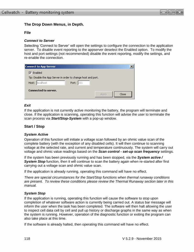
118 V 5.2.9 - November 2015
The Drop Down Menus, in Depth.
File
Connect to Server
Selecting ‘Connect to Server’ will open the settings to configure the connection to the application server. To disable event reporting to the appserver deselect the Enabled option. To modify the host and port settings (not recommended) disable the event reporting, modify the settings, and re-enable the connection.
Exit
If the application is not currently active monitoring the battery, the program will terminate and close. If the application is scanning, operating this function will advise the user to terminate the scan process via Start/Stop-System with a pop-up window.
Start / Stop
System Active
Operation of this function will initiate a voltage scan followed by an ohmic value scan of the complete battery (with the exception of any disabled cells). It will then continue to scanning voltage at the selected rate, and current and temperature continuously. The system will carry out voltage and ohmic value readings based on the Scan control - set-up scan frequency settings.
If the system has been previously running and has been stopped, via the System active / System Stop function, then it will continue to scan the battery again when re-started after first carrying out a voltage scan and ohmic value scan.
If the application is already running, operating this command will have no effect.
There are special circumstances for the Start/Stop functions when thermal runaway conditions are present. To review these conditions please review the Thermal Runaway section later in this manual.
System Stop
If the application is running, operating this function will cause the software to stop upon completion of whatever software action is currently being carried out. A status bar message will inform the user when the task has been completed. The software will then halt allowing the user to inspect cell data cell by cell and pull up history or discharge graphs in the same way as when the system is running. However, operation of the diagnostic function or exiting the program can also take place at this time.
If the software is already halted, then operating this command will have no effect.

V4
NOTE: If the Cellwatch is stopped, Cellwatch will not monitor the battery. This means that thermal runaway protections, discharge detection, and voltage, ohmic and temperature measurements are all stopped until the system is activated again.
Discharge
View discharge file
Discharge files are one of three data formats that Cellwatch actively saves data into. Discharge files are .dis files that contain data points of voltage, current, and temperature measurements taken from the battery during the discharge event. During a discharge event Cellwatch data will be saved into a temporary discharge file format to preserve the data should the iBMU lose power during the discharge event. After the completion of the discharge, the data will be converted to the standard .dis format.
A discharge file is created when the alarm setting for current outflow has been exceeded. Selecting this function enables the user to open any previous discharge file (*.dis) on this computer or any other connected by network.
The name format is yy-mm-dd_hr-mn-sc_batteryname.dis.
A discharge file may be viewed at any time, regardless of the functional status of the Battery Monitoring System. Equally a discharge file may be viewed by a different computer. However care should be taken directly viewing files used by the iBMU across a network. Please consult the section later in this guide entitled Review the Data from the System across a network. For more detailed look at the function available in the discharge graph window, see Graphical Displays, The Discharge Window (Chapter 4.).
Note; data files are only created for strings or batteries that are detected to be in discharge. Data is only included in those files for cells or jars that were in the battery in discharge.
History
View cell history
Selecting this option enables the user to review previous Battery Monitoring history (*.his) files. When Cellwatch transitions into a new day (following midnight), the previous day’s data points are compiled together into an average value for the day. These data points can be used to help identify failing cells or other problems that may affect the battery, like improper battery temperature.
When History > View History is selected the application will automatically compile the history files in the Cellwatch directory into one data record. History files are saved in the format historyXXXX.his, where XXXX indicates the year the data was collected. While files are saved by the year, when viewed they are compiled together giving a complete battery history.
This graph screen is completely described in the later section of this handbook covering Graph Windows.
If there is less than two days data, the system will advise the user that the graph cannot be displayed due to lack of data and return to the main application.
Recharge (Non-Alarming Event)
View recharge file

120 V 5.2.9 - November 2015
Recharge files are .rch files that contain data points of voltage, current, and temperature measurements taken from the battery during the charge event. During a charge event Cellwatch data will be saved into a temporary charge file format to preserve the data should the iBMU lose power during the charge event. After the completion of the charge event, the data will be converted to the standard .rch format.
A recharge file is created when the setting for input current has been exceeded. Selecting this function enables the user to open any previous recharge file (*.rch) on the iBMU or any other networked iBMU.
The name format is yy-mm-dd_hr-mn-sc_batteryname.rch.
A recharge file may be viewed at any time, regardless of the functional status of the Battery Monitoring System. It will open and display like a discharge file.
Note; data files are only created for strings or batteries that are detected to be in a recharge state. Data is only included in those files for cells or jars that were in the battery in recharge.
Scan Control
Scan voltage now
This function is only available if the system is active. Selecting this function will cause the application to complete one entire system wide voltage read. This data will be recorded in the daily history file and included in the cell and battery history as part of the daily average data. The following files will be updated:-
the voltage displayed in the cell pop-up box next time it is opened
the voltage data points in Today’s Cell Voltage & Ohmic value Graph Window next time it is opened
The starting point for any subsequent discharge file within 24 hours
The history file will only be updated with the average of the day’s readings at midnight.
This option will be unavailable if constant voltage scanning is enabled, see below.
Scan ohmic value now
This function is only available if the system is active. Selecting this function will cause the application to complete one entire system wide ohmic value read. This data will be recorded in the daily history file and included in the cell and battery history as part of the rolled up daily average data.
Ohmic value readings are deliberately taken less frequently than voltage readings due to the slow rate at which batteries change on any given day. While the power requirements for the ohmic value scan are very small allowing Cellwatch to scan more than twice per day, it is not recommended to continuously test the ohmic value of the monitored cells. To avoid damage to the Battery Monitoring System both hardware and software protection is built into the system. Hence if this function is manually invoked too often (at less than 1 minute intervals, for instance), an error message or lack of reading may occur.
Once started, the following items will be updated by scanning the battery:-
the Ohmic value displayed on the cell pop-up box
the Ohmic value data points in the Today’s Cell Voltage & Ohmic Value Graph Window
The history file will only be updated with the average of the day’s readings at midnight.

V4
This option will be unavailable if Cellwatch is already performing an ohmic value scan.
Scan settings
Selecting Scan Settings from the Scan Control menu invokes a powerful user option selection box. This box has 3 controls.
Automatically start scan on application launch.
Selection of this tick box allows the user to program the system to automatically run whenever the Cellwatch application is launched. This ensures that Cellwatch is always running whenever the iBMU is powered up. Clearing this box, means that user intervention has to take place in order to start the system if the application stops for any reason. Note the factory shipped, default condition is with this box checked. By default, it is recommended to leave this setting unchanged. Should the power to the iBMU fail, this ensures that when power is restored and Cellwatch starts again, Cellwatch will begin monitoring the batteries automatically.
Voltage Scan Frequency
The user is offered the choice of either continuous, 24, or 4 voltage readings per day. Constant voltage scanning will cause Cellwatch to monitor the voltage of the cells as quickly as possible. A sample of the data is taken every 5 minutes to be compiled for historical purposes. The most recent data can be obtained by hovering over the cell, Modbus protocols, or via the webpage interface. The results from these readings are averaged on a daily basis at the midnight updating of the History file.
For additional information please review the Constant Voltage scanning section described later in this manual.
Ohmic value Scan Frequency
The user is offered a choice of 1 or 2 ohmic value scans per day as shown in the illustration above. Default setting is once per day and should be left in this mode unless advised otherwise. The results from these readings are averaged out on a daily basis prior to the midnight updating of the History file.
Alarms
The Alarms drop down menu gives access to three functions described in order below:
Set global battery alarms
There are seven global parameters measured and monitored that will trigger an alarm. These are; temperature, current, cell voltage, string voltage, ohmic value, ripple voltage, and recharge current.
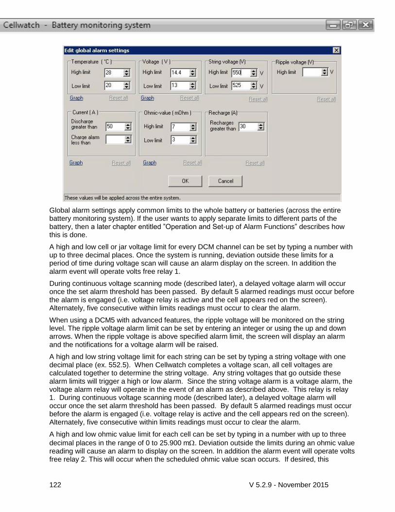
122 V 5.2.9 - November 2015
Global alarm settings apply common limits to the whole battery or batteries (across the entire battery monitoring system). If the user wants to apply separate limits to different parts of the battery, then a later chapter entitled ”Operation and Set-up of Alarm Functions” describes how this is done.
A high and low cell or jar voltage limit for every DCM channel can be set by typing a number with up to three decimal places. Once the system is running, deviation outside these limits for a period of time during voltage scan will cause an alarm display on the screen. In addition the alarm event will operate volts free relay 1.
During continuous voltage scanning mode (described later), a delayed voltage alarm will occur once the set alarm threshold has been passed. By default 5 alarmed readings must occur before the alarm is engaged (i.e. voltage relay is active and the cell appears red on the screen). Alternately, five consecutive within limits readings must occur to clear the alarm.
When using a DCM5 with advanced features, the ripple voltage will be monitored on the string level. The ripple voltage alarm limit can be set by entering an integer or using the up and down arrows. When the ripple voltage is above specified alarm limit, the screen will display an alarm and the notifications for a voltage alarm will be raised.
A high and low string voltage limit for each string can be set by typing a string voltage with one decimal place (ex. 552.5). When Cellwatch completes a voltage scan, all cell voltages are calculated together to determine the string voltage. Any string voltages that go outside these alarm limits will trigger a high or low alarm. Since the string voltage alarm is a voltage alarm, the voltage alarm relay will operate in the event of an alarm as described above. This relay is relay 1. During continuous voltage scanning mode (described later), a delayed voltage alarm will occur once the set alarm threshold has been passed. By default 5 alarmed readings must occur before the alarm is engaged (i.e. voltage relay is active and the cell appears red on the screen). Alternately, five consecutive within limits readings must occur to clear the alarm.
A high and low ohmic value limit for each cell can be set by typing in a number with up to three
decimal places in the range of 0 to 25.900 m. Deviation outside the limits during an ohmic value reading will cause an alarm to display on the screen. In addition the alarm event will operate volts free relay 2. This will occur when the scheduled ohmic value scan occurs. If desired, this
V4
function can be delayed later into the day using the Minutes into day function in the .ini file described later.
Additionally, Cellwatch has the ability to average the ohmic value readings to create a rolling average ohmic value alarm. This is useful for when customers want a delayed ohmic value alarm and ohmic averaging to take place. Additional information can be found in the Cellwatch.ini section.
A high and low temperature limit in degrees Celsius or Fahrenheit, can be set that will apply to all
the temperature probes in the system, by typing in an integer in the range 2 to 80C. Deviation outside these limits for any period of time during a temperature reading will cause an alarm display on the screen. In addition the alarm event will be triggered the volts free relay 3.
High discharge current and low charge current limits for each current clamp can be set by typing an integer in the range 0 to 1,000 Amps, or higher if current scaling is enabled. Deviation outside these limits for any period of time during normal operation will cause an alarm display on the screen. In addition the alarm event will be triggered the volts free relay 4. When the current is greater than the “Discharge greater than” value set, the discharge monitoring routine in the software is activated and a discharge file is created.
If a 1,000 Amp current clamp is being used and charge levels are very low (below 10 amps or less than 1% of the current measuring range) then it may not be possible to reliably measure the charge current and the box should therefore be left blank. If no values are set in the “Charge less than” box, that is the entry is left blank as opposed to zero, then no alarm condition will occur.
The recharge trigger limit can be set by typing an integer in the range of 0 to 1,000 Amps. If the current clamp detects a positive current above the specified limit, a recharge alert will be displayed on the screen in the form of a charge symbol on the string and battery tab. The recharge file will be created for events where the positive current above the alarm limit lasts longer than the defined qualification time. The default qualification time is 5 seconds.
If any data input box label is grayed out because a lower level (battery, string or cell) element has individual alarm levels set then data cannot be entered at a Global (or system) level.
Alarm levels can be graphed to determine which batteries, strings, or cells are different. Also, all alarm settings for the functions above can be set to the same values by selecting the reset button. This is a password protected feature and will require the engineering password ‘deafcat’ to enact. All values (battery, string, and cell) will be set to the value of the first battery, first string, and first cell in Cellwatch.
Audible Alarm
Selecting this function, indicated by a ‘tick’ or check mark to the left of the menu item enables the alarm sounder in the CU/TRC. The alarm sounder will operate whenever an alarm function is triggered and remains active, that is when any alarm relay is set and the battery panel tab in Cellwatch is red. The sound periodicity depends upon the alarm function triggered and the exact architecture of the battery.
If enabled via Windows on the iBMU, the default sound on the computer will also operate when an alarm occurs.
Reset alarm indications

124 V 5.2.9 - November 2015
To clear an alarm function, its relay, its red tab and its sounder if operating, click on the reset alarm indicators function on the Drop down menu. Alternatively select Alt-A, then R.
If the temperature or current alarm condition still meets the alarmed criteria then resetting the alarm will be followed immediately by the alarm re-enabling. Cell voltage, string voltage and ohmic value alarms occur if the condition exists during the next scheduled scan.
Reset Alarm Indicators during a Thermal Runaway Warning
Users are unable to reset alarms that pertain to thermal runaway events. All other voltage, ohmic, current, and temperature alarms can be reset by the user and their respective alarm indicators will clear. The system will follow normal scan routines and algorithms to determine if the alarm is still present during the next scheduled scan.
Configuration
H/W Detect
This screen is only accessible if a password is available to the user and cannot be accessed when the system is active. It allows an installer to access the set-up files for the system that will permit establishment of the system architecture. The user should not edit it and the resulting file will not allow Cellwatch to operate as it is missing vital battery configuration information.
View Configuration
Allows the user to see, and with security provisions via a password function, edit the currently employed hardware configuration grid.
Load Configuration.
Allows the user to load a configuration grid into the viewer and ultimately into the Cellwatch program itself, note this does not immediately affect the operation of the program as it must be restarted for this to take effect.
Users may be prompted to delete the .xcfg file if it does not match the configuration (.cfg) file. Doing so will require users to re-enter some alarm settings.
BMS interface
This function allows a number of protocols used for interface to battery monitoring systems to be turned on and off. These protocols are:-
Gateway: A simple messaging system over a second RS232 serial link.
MODBUS TCP/IP: A network protocol used for communication to building or facilities management systems.
Additional information about the Modbus registers can be found on the appnotes page at http://www.cellwatch.com/appnotes. This specification outlines the Modbus registers and how to interpret the data in each register. The information in this document is beyond the scope of this manual.
Browser Interface: A web interface for viewing data and alarm levels over a network or the Internet.

V4
Diagnostics
System Test
This function cannot be invoked while the Cellwatch software is actively monitoring the battery. The software must be stopped first and then “Diagnostics” selected from the menu bar.
If the system is not active, operation of this command gives access, via a password to a diagnostic window. Nothing in this diagnostic functional area can damage the Cellwatch system.
The left hand third of the screen is occupied by an information window above and device address control panel below. The Port and Control Unit addresses have to be correct for the diagnosis system to work. When working with a system that contains 1 or more Thermal Runaway Controllers the CU address box can be used to access the TRC in the same manner.
RVD - Request Voltage Data
RVD allows the user to collect voltage data from a DCM, units ‘1’ to ‘254’, or current and temperature data from a Control Unit if the Unit number is ‘0’. Selecting RVD (Request Voltage Data) in the central, command area of the window will return temperatures and currents for both current and temperature ports 1 and 2 if a Control Unit (Cellwatch Unit ‘0’) is selected. These are displayed in windows marked Temperature and Current on the right hand side of the screen.
Increasing the Cellwatch unit to 1 and above returns voltage data from DCM number 1 (and above) when RVD is pressed again. Voltage data is visible in the Voltage box on the right of the screen.
126 V 5.2.9 - November 2015
SDC, CDC- Set, Clear Dry Contact (a.k.a. volt-free contact)
When the Cellwatch Unit is set to ‘0’, referring to a Control Unit, pressing SDC & CDC sets and clears the volts free contacts selected using the channel address selector. In this way, peripherals connected to these volts free contacts that will be operated by the alarm function can be easily tested without interference with the battery.
Volt free contact 5 is not normally accessible as it will only activate if there is no RS-485 communication, indicating that the Cellwatch software has been stopped or the IBMU has been powered off. Relays 6 to 10 on the TRC are not normally accessible as they could be configured to remove a critical UPS string from operation. To test these relays please see the Thermal Runaway section of this manual.
RTU - Request type of unit.
Setting the Unit Address to different values and operating RTU (Request Type of Unit) will return type C for a Control Unit, 4T for a TRC, and a Z for a voltage and ohmic value DCM.
TFO – Test Fiber Loop
When enabled, this command will depress and all other Diagnostics commands will be disabled. Once enacted the selected Control Unit will send a signal around the fiber loop in attempts to help troubleshoot if and why a broken fiber loop exists. DCM EX and above will flash when this command is enabled allowing for quicker location. Refer to the Troubleshooting chapter in the hardware section of the manual for additional information.
Illegal Requests
If an illogical or illegal request is made, then pop-up boxes advise the user where and when certain instructions may be used. For instance, an RSD cannot be used with a Cellwatch Unit 0 (Control Unit) and a pop up box will appear advising the user of this if attempted.
Help
About
This panel gives the version number as well as your license serial number and other information relating to the Cellwatch software. This version number should always be quoted when contacting your supplier for assistance.
GRAPHICAL USER INTERFACE (GUI)
This section will review the graphical user interface and highlight the primary features.
Activity indicator
To indicate the activity of the Cellwatch system, a moving ‘searchlight’ will be active all the time that Cellwatch is operating correctly. Under these circumstances the moving logo confirms the continued operation of Cellwatch. This logo can be found in the top right hand corner of the window when Cellwatch is running.
If the logo is not visible, the Cellwatch system has been stopped by the user or because Cellwatch has been unable to communicate with at least 1 CU/TRC.

V4
The Status Window
The status window appears directly under the drop down menus and keeps the user informed as to what is happening in the system. In the example below it is taking readings of String 1, 2, and 3 on Battery 1 at 4:32:09 PM.
When the system is stopped, the clock in the status window will stop, indicating what time the system was halted.
Alerts Panel
The alerts panel provides important information about the status of the Cellwatch system. Critical events will appear in red such as thermal runaway events. Other events will appear with a red icon.
Options will be provided to help fix the problem. As shown to the right Cellwatch is notifying the user of thermal events that were suspended due to Cellwatch not scanning. Clicking the ‘Start scanning’ link will automatically re-enable the Cellwatch system.
Not Scanning
This event indicates that the Cellwatch system is not actively scanning the battery. To clear either click ‘Start scanning’ or select the Start/Stop drop down menu and activate the Cellwatch System.
Thermal Warning Relay Tripped
This event indicates that conditions on one or more strings and/or batteries indicate that thermal runaway may be taking place. With Cellwatch 4.2 and DCM 5, thermal runaway can now be triggered on a per jar basis when a jar’s temperature crosses the string alarm threshold and the other thermal runaway monitored conditions occur. When present this indicates that Relay 10 is active warning users of the impending disconnect. Users may clear the relay from the alerts window if desired. The warning will not reappear until a string has been disconnected or a new string enters a thermal warning state.
Thermal Disconnect Timer
This event indicates that conditions for a thermal runaway event are detected. This will appear when both thresholds for thermal conditions (voltage and temperature) have been detected. A countdown will be displayed indicating the remaining time until Cellwatch attempts to take the string offline. Users can delay the string disconnect by selecting ‘Delay’. Events are delayed in increments of 12 hours (by default but this can be changed in the .ini file) to a maximum of 24 hours.
Thermal Disconnect
This warning indicates that Cellwatch has removed as string from operation. To re-arm the relay for this string, select re-arm’ to reengage the string for thermal protection. Note that if Cellwatch detects thermal conditions again, it will initiate the delay countdown again; even though the breaker has not been confirmed to be closed by the user. Date and time of the disconnect event will remain visible until the relay has been reengaged.

128 V 5.2.9 - November 2015
The Battery Panel.
Located below the status window is the battery / string panel area. This area shows the architecture of the cells or jars in relationship to the strings and battery as a whole. It also provides, through colored cell depictions, an indication as to the alarm status of each cell as well as access to individual cell and string charts. The illustration here shows a complex array of 12 batteries. The visible battery "B43" has a single string (String B) of 240 jars or mono-blocs.
The panel allows for multiple;
Batteries: - A single or multiple strings configuration connected to a UPS or DC charger.
Strings:- A single or multiple series jar/cell/block configuration monitored by Cellwatch
Cells, jars or mono-blocs: - the lowest denominator of a system, depicted by a colored panel.
The panel is broken up into distinct areas. The top area represents the battery and string summary details on tabs while the panel below indicates the jars or cells. Right and left clicking these areas or the cell depictions gives access to a number of shortcuts and functions described below.
The Battery Tabs
Battery tabs contain summary information for the monitored battery. A status indicator to the left of the tab indicates the presence of any alarm within the monitored battery (i.e. if a single measurement point on a cell within a string on that battery indicates an alarm, the summary alarm will be Red). A battery configuration may contain multiple strings, as in redundant n+1 configurations. Battery labels are defined in the configuration file by the Battlbl column.

V4
The current displayed in the battery tab is a summary of individual string currents monitored by Cellwatch. Left clicking a battery tab will select the battery displaying the individual strings associated with the battery below in the String section. Hovering over the tab will provide an alarm summary. Right clicking the tab will provide options that allow the user to configure the battery with different alarms from the overall system level.
The String Tabs
For each battery configured on the system, there will be a minimum of one string monitored. This is configured with the configuration builder on system setup. Each string’s set of cell or jar depictions can be displayed in the panel by left clicking on the string tab. Each tab will bear the label of the string as set up in the configuration grid in the column ‘Strlbl’. This label can be numeric, alphabetic or a combination of the two.
The string tab will contain an alarm indicator that will turn red if there is any current, temperature, voltage, string voltage, or ohmic value alarm on that string or on any cells in that string. In addition adjacent to the String label on the tab, the actual string voltage will be displayed after the first voltage scan has taken place. This data will be updated continuously following voltage scans.
Right clicking on these tabs access the control menu for the string. Hovering the mouse cursor over the string tab causes a pop-up box to appear detailing the battery and string labels and the value of any current and temperature probes associated with that string.
INFORMATION CONTAINED IN THE BATTERY PANEL
The Cell Depictions.
Each rectangular block in the string panel depicts a measurement point and can represent a single cell / mono-bloc / jar or number of cells / jars / mono-blocs. The numbers contained in each block are the references entered in the batconfig.cfg grid in the columns; Blk Fr (Block From) and Blk To (Block To). These references must be numeric integers (whole numbers) and usually relate directly to labels fitted to the cells by the battery installer.
Only BlkFr is essential to display information in the panel. BlkTo is optional and assists the user where a measurement channel is across several cells or jars.
The color scheme
White: On initialization all cell depictions shown in the battery panel are colored white. This indicates that Cellwatch has yet to be started for the first time and as such, Cellwatch is unaware whether these cells are within alarm limits (Green) or outside alarm limits (Red).
When Cellwatch starts scanning a voltage scan takes place and the cell depiction will turn yellow until measurements from the cell indicate a change in color to either green or red as expected.
Green. Following a voltage or ohmic value scan the cell depictions will turn green if the results received were between the alarm limits set for that cell.
Yellow. The blocks become yellow when an action is taking place. This can either be a voltage or an ohmic value reading. The block will revert to Green, Red or Grey determined by the
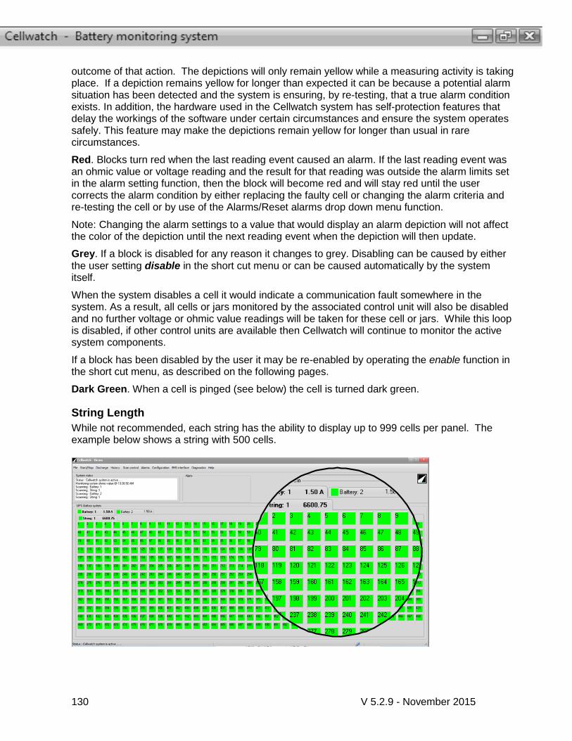
130 V 5.2.9 - November 2015
outcome of that action. The depictions will only remain yellow while a measuring activity is taking place. If a depiction remains yellow for longer than expected it can be because a potential alarm situation has been detected and the system is ensuring, by re-testing, that a true alarm condition exists. In addition, the hardware used in the Cellwatch system has self-protection features that delay the workings of the software under certain circumstances and ensure the system operates safely. This feature may make the depictions remain yellow for longer than usual in rare circumstances.
Red. Blocks turn red when the last reading event caused an alarm. If the last reading event was an ohmic value or voltage reading and the result for that reading was outside the alarm limits set in the alarm setting function, then the block will become red and will stay red until the user corrects the alarm condition by either replacing the faulty cell or changing the alarm criteria and re-testing the cell or by use of the Alarms/Reset alarms drop down menu function.
Note: Changing the alarm settings to a value that would display an alarm depiction will not affect the color of the depiction until the next reading event when the depiction will then update.
Grey. If a block is disabled for any reason it changes to grey. Disabling can be caused by either the user setting disable in the short cut menu or can be caused automatically by the system itself.
When the system disables a cell it would indicate a communication fault somewhere in the system. As a result, all cells or jars monitored by the associated control unit will also be disabled and no further voltage or ohmic value readings will be taken for these cell or jars. While this loop is disabled, if other control units are available then Cellwatch will continue to monitor the active system components.
If a block has been disabled by the user it may be re-enabled by operating the enable function in the short cut menu, as described on the following pages.
Dark Green. When a cell is pinged (see below) the cell is turned dark green.
String Length
While not recommended, each string has the ability to display up to 999 cells per panel. The example below shows a string with 500 cells.

V4
Shortcuts Summary
There are numerous shortcuts activated by a combination of mouse keys and differing panel locations. Here is a summary of these.
Right Click on the String Panel
Moving the mouse pointer over anywhere in the main panel area and right clicking the mouse button reveals a number of extra controls via a shortcut menu that appears in the panel.
String “label”
This shows the String label as set-up in the configuration grid.
String h/w ID.
Selecting this function provides a list of all the current clamp and temperature probe address information relating to the string.
String Voltage
This function returns the String voltage summary for the string.
Graph Latest Readings
This option allows the user to display a graph of the latest voltage and ohmic measurements for the monitored channels. If constant voltage scanning is enabled then selecting this option will display the most recent voltage measurement and the sample points collected throughout the day. When selecting on the string level, Cellwatch will present a graph with the latest measurements on all channels on the string. When selecting on the cell level, Cellwatch will present a graph of the most recent measurement on that cell and sample points throughout the day.
Perform String Ohmic Scan
This option allows users to perform an ohmic value scan on a single string in an attempt to get the most recent data or to clear an alarm.
Set Global Alarms
This function gives access to the Global battery alarm set-up screen.
Set alarm limits for this Battery only
This function allows the user to set custom alarm limits for this battery only. All other alarm limits are as set in Set Global Alarm. See Chapter 7 for a more detailed explanations.
Set alarm limits for this String only
This function allows the user to set custom alarm limits for this string only. All other alarm limits are as set up in Set Global Alarm or the previous function. See Chapter 7 for a more detailed explanations.
Autoset String Ohmic Alarms
This feature allows users to set custom alarm limits for individual cells within the string. Once run, this option cannot be run again unless the user resets all cells in the string to have the same

132 V 5.2.9 - November 2015
ohmic value alarm settings. Additional information can be found in the Autoset Ohmic Alarms section.
Thermal Runaway Protection
This option allows users to enable thermal runaway protection for the string. Access to this option requires the string to be configured on a Thermal Runaway Controller and not a Control Unit. Additional information can be in the Configure Thermal Runaway section of this manual.
Enable
The whole string may be enabled, following either an automatic or manual disablement using this function.
Disable
The whole string may be disabled using this function. This is only available when the software is stopped. At other times, it is grayed out.
Right Click on a Cell
Moving the mouse pointer over a cell depiction and right clicking the mouse button reveals a number of extra controls via a shortcut menu.
These are:-
Cell Label
This shows the system hardware identification number that is sequentially generated by the system. It is neither the cell name nor the cell label set up in the configuration grid.
Cell h/w ID
This is the route, through the hardware architecture to this particular cell or jar or block. It is detailed by serial port number, CU/TRC number, DCM number and Channel number (with DCM firmware version number). For a more detailed explanation of these parts see the installation section, towards the front of this manual.
Cell History
This function enables direct access to the View History capability for a particular cell. It is similar to the View Cell History function but instead of only entering the data for a particular year selected (as does the History/View Cell History drop down menu) it attempts to find at least 120 days of history from the current date and will resort to previous years history if that is available. If there is not sufficient history in this year’s history file or last year’s, it will show what history is available.
Alarm reason
In the event that an alarm is indicated, the reason for the alarm being set can be viewed in this location. If an alarm has been triggered for that cell, it will either indicate that an ohmic value measurement or a voltage measurement or both has triggered the alarm.
Set alarm limits for this Cell only
This function allows the user to set custom alarm limits for this cell only. All other alarm limits are as set up in a higher alarm setting function. See Chapter 7 for a more detailed explanations.

V4
Ping Continuous
This function is unavailable when Cellwatch is active. When enabled, the selected cell will turn dark green. Cellwatch will identify the cell represented by sounding a buzzer and flashing an LED on the DCM identified in the Hardware ID.
Selecting another cell by a right click will cause the ping function to move to the new cell. This feature is best utilized identifying alarmed or faulty jars and verifying cell labels in Cellwatch against the battery string.
Enable
This function will enable a previously user disabled block and allow readings to be taken.
Disable
Regardless of the run state of the program, a bloc can be disabled from being monitored at any time. When this is done the menu item remains ticked and the depiction in the panel is turned to grey. Re-enabling the block or cell is done by selecting the enable function, removing the tick and the cell is reactivated back to its original color.
Left Click on a cell
Left mouse button operation while hovering over a cell depiction will invoke the Cell Voltage and Ohmic value (also Temperature if using DCM5) Graph as described in the next section of this handbook.
Hover over a Cell in the Panel.
If the mouse cursor is hovered over any cell depiction in the string window for a few seconds, a pop-up box appears providing a summary of the cell voltage and ohmic value and the times they were last read.
Hover over a Battery Tab.
If the mouse cursor is hovered over any battery tab for a few seconds, a pop-up box appears providing a summary of the temperature, current, voltage and ohmic value alarm status. This status will indicate the reason for an alarm condition if the Battery Tab is red.

134 V 5.2.9 - November 2015
Hover over a string tab.
Hovering the mouse cursor over the string tab causes a pop-up box to appear detailing the battery and string labels and the value of any current and temperature probes and the string voltage associated with that string.
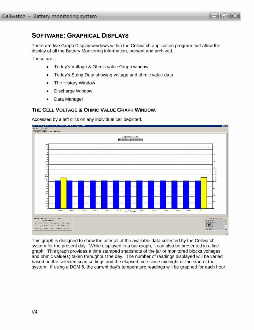
V4
SOFTWARE: GRAPHICAL DISPLAYS
There are five Graph Display windows within the Cellwatch application program that allow the display of all the Battery Monitoring information, present and archived.
These are:-,
Today’s Voltage & Ohmic value Graph window
Today’s String Data showing voltage and ohmic value data
The History Window
Discharge Window
Data Manager
THE CELL VOLTAGE & OHMIC VALUE GRAPH WINDOW.
Accessed by a left click on any individual cell depicted.
This graph is designed to show the user all of the available data collected by the Cellwatch system for the present day. While displayed in a bar graph, it can also be presented in a line graph. This graph provides a time stamped snapshots of the jar or monitored blocks voltages and ohmic value(s) taken throughout the day. The number of readings displayed will be varied based on the selected scan settings and the elapsed time since midnight or the start of the system. If using a DCM 5, the current day’s temperature readings will be graphed for each hour.
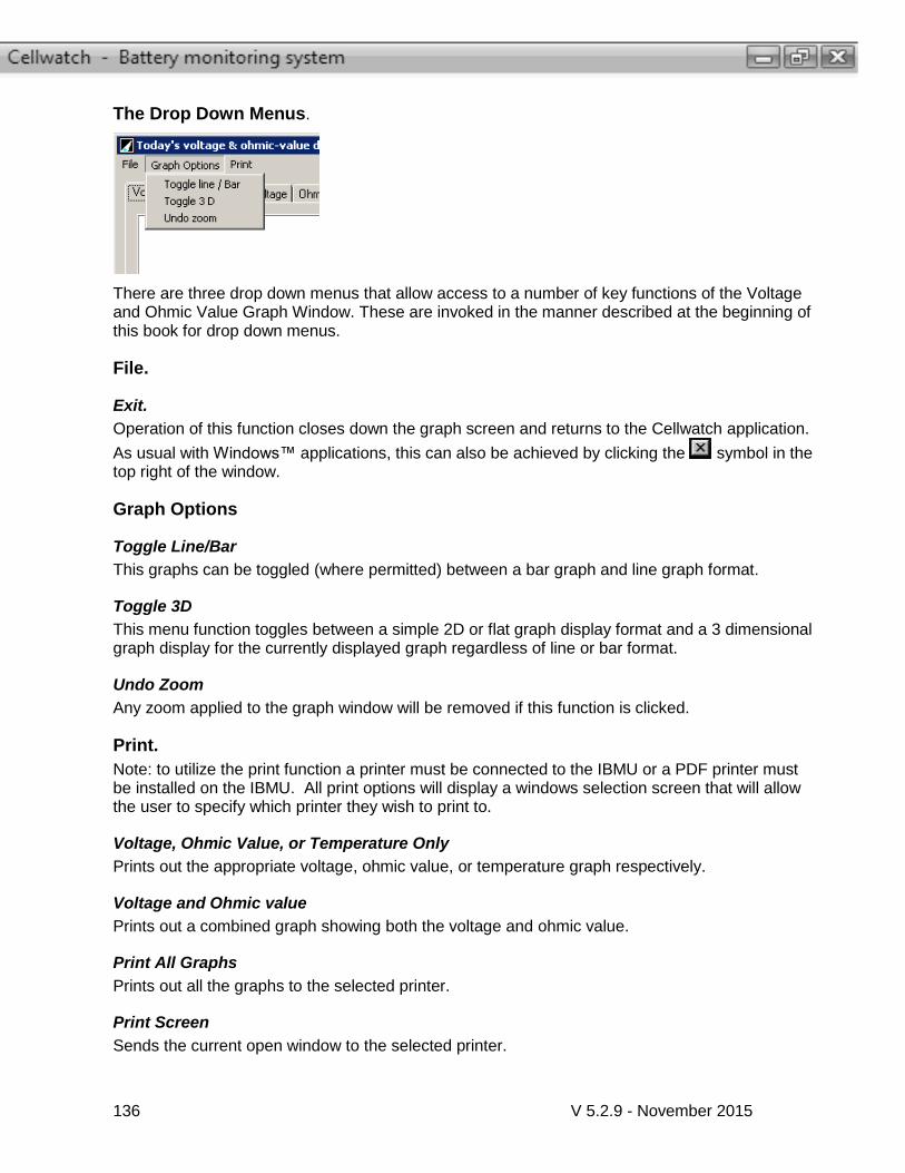
136 V 5.2.9 - November 2015
The Drop Down Menus.
There are three drop down menus that allow access to a number of key functions of the Voltage and Ohmic Value Graph Window. These are invoked in the manner described at the beginning of this book for drop down menus.
File.
Exit.
Operation of this function closes down the graph screen and returns to the Cellwatch application.
As usual with Windows™ applications, this can also be achieved by clicking the symbol in the top right of the window.
Graph Options
Toggle Line/Bar
This graphs can be toggled (where permitted) between a bar graph and line graph format.
Toggle 3D
This menu function toggles between a simple 2D or flat graph display format and a 3 dimensional graph display for the currently displayed graph regardless of line or bar format.
Undo Zoom
Any zoom applied to the graph window will be removed if this function is clicked.
Print.
Note: to utilize the print function a printer must be connected to the IBMU or a PDF printer must be installed on the IBMU. All print options will display a windows selection screen that will allow the user to specify which printer they wish to print to.
Voltage, Ohmic Value, or Temperature Only
Prints out the appropriate voltage, ohmic value, or temperature graph respectively.
Voltage and Ohmic value
Prints out a combined graph showing both the voltage and ohmic value.
Print All Graphs
Prints out all the graphs to the selected printer.
Print Screen
Sends the current open window to the selected printer.

V4
Graph Data Source Tabs.
Voltage & Ohmic Value / Voltage / Ohmic Value tabs.
These tabs present choices between three graphs of information collected between midnight and the time of viewing. The title of each tab is self-explanatory.
The Information Area
The Graph Area
The upper portion of the information area is dominated by the graph selected using the tabs. The format of the graph is altered by use of the “Graph option” drop down menu. The X axis shows the time of day the measurement readings was taken. The Y axis shows the recorded values, either volts or ohmic value or both.
To zoom, draw a rectangle box using the cursor and the left mouse button beginning from the upper left to the lower right diagonally selecting the area you wish to expand. The selected area will be magnified to fill the graphical display window.
To reverse the zooming action, draw a rectangle of any size from the lower right toward the upper left while holding the left mouse button or by double clicking in any portion of the graph. The graph will revert to full size once again.
To ‘pan’ the graph area, that is to move the graph image sideways or up or down in the viewing window, position the cursor over a background part of the graph window and while holding down the right mouse button move the mouse either up or down or from side to side.
The Cell Data Area
The grey box, to the bottom left of the window details the minimum and maximum readings in both voltage and ohmic value made since midnight of the previous day as well as the total number of readings taken since that time. It also shows the calculated average reading.
The Voltage / Ohmic Value Readings Area
The day’s data of both types; voltage and ohmic value are displayed in the lower right hand side of the window under the banner: Voltage / Ohmic Value Readings. The order of presentation is such that the oldest data is at the top of the list and the newest below.
Note, on this list, ohmic value readings will adopt the same order number of the prior, related voltage reading as this will have been taken at (almost) the same time.
Note.
Graph windows should always be closed when no longer used. They display information captured at the moment in time the graph is opened, and are not updated with information as it is gathered so should not be left open for long periods. Closing the graph and re-opening the same graph will update the data.
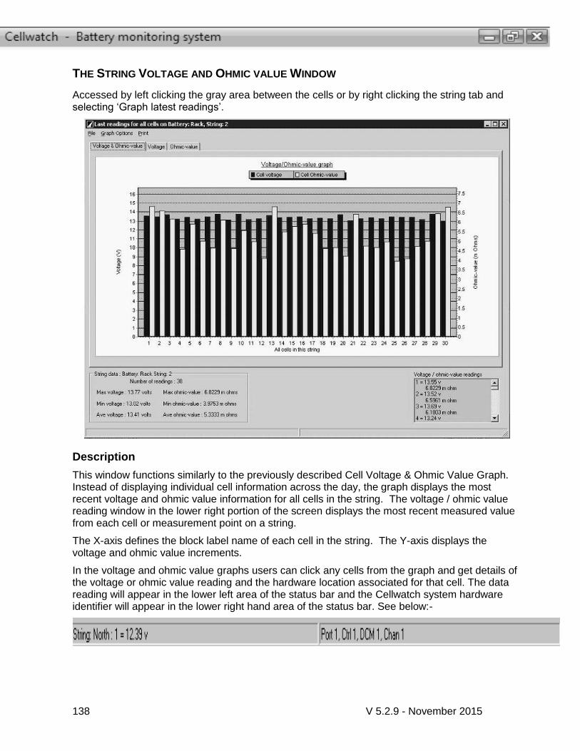
138 V 5.2.9 - November 2015
THE STRING VOLTAGE AND OHMIC VALUE WINDOW
Accessed by left clicking the gray area between the cells or by right clicking the string tab and selecting ‘Graph latest readings’.
Description
This window functions similarly to the previously described Cell Voltage & Ohmic Value Graph. Instead of displaying individual cell information across the day, the graph displays the most recent voltage and ohmic value information for all cells in the string. The voltage / ohmic value reading window in the lower right portion of the screen displays the most recent measured value from each cell or measurement point on a string.
The X-axis defines the block label name of each cell in the string. The Y-axis displays the voltage and ohmic value increments.
In the voltage and ohmic value graphs users can click any cells from the graph and get details of the voltage or ohmic value reading and the hardware location associated for that cell. The data reading will appear in the lower left area of the status bar and the Cellwatch system hardware identifier will appear in the lower right hand area of the status bar. See below:-

V4
THE HISTORY WINDOW
Accessed by the History drop down menu.
The history graph provides historical data for each cell, current probe, and temperature probe monitored. Information is compiled daily at midnight into an average reading for the day and added to a history file. This graph will automatically display the last 120 days of data by default. Users can adjust the dates displayed to show all the available data for that battery, or as little as 2 days of data. Users can also select individual cells, strings or batteries to display.
History files can be found in the C:\Program Files\Cellwatch directory and will be labeled as HistoryXXXX.his, where XXXX equals the year (i.e. History2014.his will contain data for 2014).
The Drop Down Menus.
There are three drop down menus that allow access to a number of functions of the History Graph Window.
File.
Exit
Operating this function closes the History Graph Window. This has no other effect on the application.
Options
Show series markers
Each data set of the graph display has a label defining the battery and string name and cell label of the data set. These can be turned on and off using this function.
Note, if ‘Show All’ is selected in the ‘Select Cell to Plot’ the marks are automatically toggled off to prevent the screen from overcrowding. Users can toggle the markers back on if they wish to do so.
Toggle Line/Bar
This graphs can be toggled (where permitted) between bar graph style and line graphs styles.
Right and left axis controls
Allows the user to plot different data on the right and left axis.
Cell, string and battery selection controls
Easily select all cells in a string or battery.
History data controls
Allows the user to select different configurations and show or hide days in that range.

140 V 5.2.9 - November 2015
Undo Zoom
Any zoom applied to the graph window will be removed if this function is clicked. This has the same effect on the graph window as double clicking or drawing a box with the mouse pointer from right to left.
Clear Graphs
This function removes any selected cells or probes from the graph window, permitting the user to start again and select data sources to graph from the “Select Cell to Plot” area at bottom left of the window. It is the same as the ‘Hide All’ function from the ‘Select Cell to Plot’ area.
Print.
The titles in this Drop Down Menu are ‘print graph’ and ‘print window’. Printing the graph will print the displayed information in the graph window, while printing the window will print the entire history window.
Graph Radio Buttons
Users can select which graph to view by using the radio buttons at the bottom left of the history data window. Users can overlay multiple graphs (i.e. voltage and temperature) by selecting the Right Axis and a corresponding graph. Note that users cannot plot both voltage and voltage, ohmic value and ohmic value, etc… on both the left and right axis.
Selecting ‘None’ will remove the overlaid graph.
Voltage / Ohmic Value /Current and Temperature / Ripple.
By selection of these radio buttons the selected data can be viewed in graphical form. Each graph works in the same manner.
The Information Area
The Graph Area
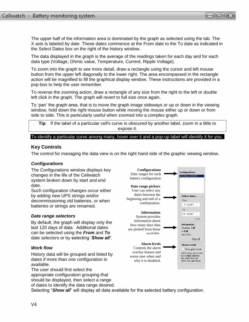
V4
The upper half of the information area is dominated by the graph as selected using the tab. The X axis is labeled by date. These dates commence at the From date to the To date as indicated in the Select Dates box on the right of the history window.
The data displayed in the graph is the average of the readings taken for each day and for each data type (Voltage, Ohmic value, Temperature, Current, Ripple Voltage).
To zoom into the graph to see more detail, draw a rectangle using the cursor and left mouse button from the upper left diagonally to the lower right. The area encompassed in the rectangle action will be magnified to fill the graphical display window. These instructions are provided in a pop-box to help the user remember.
To reverse the zooming action, draw a rectangle of any size from the right to the left or double left click in the graph. The graph will revert to full size once again.
To ‘pan’ the graph area, that is to move the graph image sideways or up or down in the viewing window, hold down the right mouse button while moving the mouse either up or down or from side to side. This is particularly useful when zoomed into a complex graph.
Tip: If the label of a particular cell's curve is obscured by another label, zoom in a little to expose it.
To identify a particular curve among many, hover over it and a pop-up label will identify it for you.
Key Controls
The control for managing the data view is on the right hand side of the graphic viewing window.
Configurations
The Configurations window displays key changes in the life of the Cellwatch system broken down by start and end date. Such configuration changes occur either by adding new UPS strings and/or decommissioning old batteries, or when batteries or strings are renamed.
Date range selectors
By default, the graph will display only the last 120 days of data. Additional dates can be selected using the From and To date selectors or by selecting ‘Show all’.
Work flow
History data will be grouped and listed by dates if more than one configuration is available. The user should first select the appropriate configuration grouping that should be displayed, then select a range of dates to identify the data range desired. Selecting “Show all” will display all data available for the selected battery configuration.
Configurations
Date ranges for each
battery configuration
Date range pickers
User can select any
dates between the
beginning and end of a
configuration.
Information System provides
information about
how many days data
are plotted from those
available.
Alarm levels
Controls the alarm
overlay feature and
warns user when and
why it is disabled.
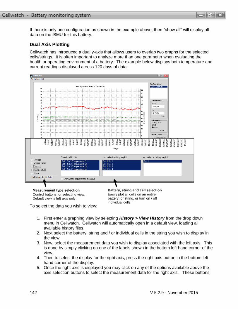
142 V 5.2.9 - November 2015
If there is only one configuration as shown in the example above, then “show all” will display all data on the iBMU for this battery.
Dual Axis Plotting
Cellwatch has introduced a dual y-axis that allows users to overlap two graphs for the selected cells/strings. It is often important to analyze more than one parameter when evaluating the health or operating environment of a battery. The example below displays both temperature and current readings displayed across 120 days of data.
To select the data you wish to view:
1. First enter a graphing view by selecting History > View History from the drop down menu in Cellwatch. Cellwatch will automatically open in a default view, loading all available history files.
2. Next select the battery, string and / or individual cells in the string you wish to display in the view.
3. Now, select the measurement data you wish to display associated with the left axis. This is done by simply clicking on one of the labels shown in the bottom left hand corner of the view.
4. Then to select the display for the right axis, press the right axis button in the bottom left hand corner of the display.
5. Once the right axis is displayed you may click on any of the options available above the axis selection buttons to select the measurement data for the right axis. These buttons
Battery, string and cell selection
Easily plot all cells on an entire battery, or string, or turn on / off individual cells.
Measurement type selection
Control buttons for selecting view. Default view is left axis only.

V4
may be changed at any time and will automatically update the view immediately after a change is made.
Alarm Level Displayed on History Graph
By selecting the “Show alarm levels” option on the graphic control screen, high and low alarm limits can be displayed on a cell-by-cell basis. This view will display an individual cell and the associated alarm levels.
The user can walk through each cell one by one by clicking to view the next cell. Multiple cells can be viewed at the same time, however the alarm limits will only be shown if all selected cells have the same alarm settings.
‘Select Cell / String / Battery to plot’ areas
Unless the history graph is selected from a cell depiction, the default view is the voltage graph showing the data-set for Battery 1, String 1, Cell 1. Only data sets relevant to the type of graph selected can be chosen from the ‘Select Cells to Plot’ window.
There are three sections in the lower portion of the window that allow users to select individual cells, strings, or batteries to plot. Selecting a string will highlight and plot all cells within the string. Selecting a battery will highlight and plot all strings and cells associated with those strings on that battery. Multiple cells or strings can be selected by simply left clicking to select or deselect a cell. Users can use the ‘Advanced select mode’ checkbox such that any item selected, cell, string, or battery, is the only item displayed.
Alarm levels in red
Dashed red lines make them easy to
distinguish from cell data
Voltage reading
The Cellwatch voltage reading for this cell is shown in black

144 V 5.2.9 - November 2015
To remove data lines while examining a graph users can left click anywhere along the line to deselect or remove it from the graph. To clear the whole graph, use the Options drop down menu or the ‘Hide all’ function as illustrated below.
By right clicking on any data set in the ‘Select Cell to Plot’ window a further drop down menu can be accessed providing four additional functions.
The selected (right clicked) cell or data set can be colored individually using the ‘Color´ function. Left clicking this menu entry accesses the Windows palette function and another color can be chosen and applied.
All the cell curves can be displayed together by selecting Show all function. These can then all be removed leaving a blank graph by left clicking on Hide all.
To change the color of all curves together (to the same color) select Color all displayed and choose a preferred color from the Windows palette presented.
Note.
Viewing the graph data has no effect on the measurement functions of the Cellwatch system. Voltage and Ohmic value measurements can be started while the window is open. If the graph window is left open during the night, the data is updated automatically, at midnight, into the history file and can be viewed by closing and re-opening the history file.

V4
THE DISCHARGE FILE
Whenever a discharge current alarm criteria for any current sensor is exceeded, Cellwatch immediately begins recording a discharge file. During this recording, voltage, current and temperature readings are taken continuously, as fast as the system will scan the battery string under discharge. If more than one battery is discharging then the system will monitor and record all batteries and record a file for each battery in discharge.
Discharge files are actively saved on the disk as temporary discharge files during the discharge event. Upon completion of the discharge the files are converted into the discharge file format for viewing with the File Viewer or within Cellwatch. If a discharge event lasts less than 5 seconds the temporary file is deleted, but record of the event is recorded in the logfiles.
If the discharge graph is for a large system and for a sustained period it can take a little while to load the graph. In this situation the load status is shown in the center of the status bar at the bottom of the program window.
Discharge file location and naming.
The discharge file created during a discharge will be located in the Cellwatch working folder or directory. It will be named after the start date and time of the discharge and the battery label given to the battery in the configuration set up. Hence a typical discharge file name will have the format:-
YY-MM-DD_hh-mm-ss_BatteryName.dis
or for example: 01-03-01_12-49-40_Bat20.dis
In the event that a large system has multiple successive discharges, with only short (say 30 second) periods of power on between them, then it may be that the system will not have

146 V 5.2.9 - November 2015
sufficient time to write the discharge files fully to disk before a 2nd or 3rd discharge starts. In this case the later discharge information will be concatenated onto the rear of the appropriate unwritten discharge file and written when the system has resources to do so.
Consequently after 2 discharges, occurring close together a 32-battery system may have only written 48 discharge files, but all discharge data will be present.
Illegal Windows characters
If a battery name is created with illegal Windows characters (e.g. < or / or %) then these characters are removed prior to writing the battery file name. Try to only use letter or number characters to name your batteries.
Battery name size
We recommend therefore that all relevant data relating to the battery is contained in the first 12 characters of a battery name and the name is restricted to as few extra characters beyond that number, as can be devised. While longer battery names can be supported (up to 50 English characters), battery names in other languages such as Korean or Chinese will have to use shorter battery names.
Discharge Information
The lower right hand area shows the start time and the stop time of the discharge. This includes the qualifying time for the discharge to become recognized by Cellwatch (the time in the .ini file). It also contains the number of readings taken for each measurement point in discharge on the battery.
NOTE: Variances in the number of readings can be caused by variances in RS-485 distances, the number of batteries in discharge, and the number of cells monitored by Cellwatch.
The Drop Down Menus
There are three drop down menus that allow access to a number of key functions of the Discharge Graph Window. These are invoked in the manner described at the beginning of this book for drop down menus.
File
Exit
This function closes the graph window.
Options
Show Series Markers
The labels on the graph indicating the source of the data for each curve on the graph can be turned on or off by the use of this control.
When all graph data points are selected for display, the labels are automatically turned off to avoid display confusion.
Undo Zoom

V4
The graph panel zoom feature can be undone by the selecting this function. When selected the graph returns to 1:1 scaling with the zero point re-established. This has the same effect as dragging the mouse pointer from top right to bottom left or double clicking anywhere on the graph.
Clear Graphs
This function removes any voltage graphs from the graph window, permitting the user to start again and select data sources to graph from the “Select Cell to Plot” area at bottom left of the window. It is the same as the ‘Hide All’ function from the ‘Select Cell to Plot’ area.
Voltage graph / Current temp graph / Print all graphs / Print window
These options allow the user to print any of the graphs. Print window sends the current open window graph to the selected printer.
The Information Area
The Graph Area
The upper half of the information area is dominated by the graph as selected by use of the tab at the top of this area. The format of the graph is altered by use of the option drop down menu. The X axis is labeled by the reading time, starting at the last voltage reading taken before the discharge occurred and ending at the last reading the system was able to take during a discharge. The timing and number of these readings are also indicated in the lower right portion of the window.
The data displayed in the graph are the readings for either voltage or temperature and current for the period of the discharge.
To zoom into the graph to see more detail, draw a rectangle using the cursor and left mouse button from the left to the right. The area drawn will be magnified to fill the graphical display window.
To reverse the zooming action, draw a rectangle of any size from the right to the left using the left mouse button or by double clicking the left mouse button. The graph will revert to full size once again.
To ‘pan’ the graph area, that is to move the graph image sideways or up or down in the viewing window, position the cursor in the background area of the graph (that is, not on a line or bar of the graph), hold down the right mouse button while moving the mouse either up or down or from side to side.
To reset the graph, select the drop down menu, Options –undo zoom.
Best and worst performing cells at the time of the last reading taken during a discharge are displayed as the default setting. All other cells will lie between these two graphs. It is advised that the user open all graphs to show the performance curves of all cells before the assumption is made that all cells are good.

148 V 5.2.9 - November 2015
The Select Cell to Plot Area
Initially there are two curves drawn in the graph area. Extra cells can be plotted by using the Select cell to plot area in the lower left hand corner of the Discharge graph window. To select a curve to add to the graph hover the mouse pointer over a cell data label and clicking once. The label should be highlighted to show it is now displayed on the graph. Repeating this process will deselect the curve from the graph.
Selecting a String will plot all cells on the string in the discharging battery. Selecting the discharging battery will display all strings and associated cells in the discharge graph. Note that only cells in the discharging battery will be graphed.
Users can use the advanced select mode to view individual cells or strings. When enabled, any left click only enables the selected cell/string/battery to be viewed, all other selected items are deselected.
When a discharge graph is invoked, its default view is the voltage graph showing the highest and lowest voltage cells at the end of the discharge. Data points on display are highlighted in the lower left hand window. By right clicking on any data set in the ‘Select Cell to Plot’ window a further drop down menu can be accessed providing four functions.
Each line or data set can be colored individually using the ‘Color´ function. Left clicking this menu entry accesses the Windows palette function and another color can be chosen and applied.
All the cell curves can be displayed together by selecting Show all function. These can then all be removed leaving a blank graph by left clicking on Hide all.
To change the color of all curves together (to the same color) select Color all displayed and choose a preferred color from the Windows palette presented.
The Discharge Information Area
Data regarding the start and end time of the discharge is displayed in this area and the number of readings recorded.
Note.
Viewing the graph data has no effect on the measurement functions of the Cellwatch system. Voltage and Ohmic value measurements can be started while the window is open. If a discharge takes place during viewing of the graph window, all data is collected in the usual manner.
Voltage Alarms during a Discharge
Voltage alarms are not uncommon during a discharge event. Remember, voltage alarms are often set to be float voltage alarms indicating that the cell is no longer at the proper charge voltage. Cells likely will go into a low voltage alarm during the discharge event simply because they are no longer at the proper charge voltage.
Following a discharge it is likely that cell voltages will be reduced considerably. Hence when the battery returns to a charging state, voltage alarms will still be set to red on the screen until voltage levels are back above Voltage Low Alarm thresholds AND a voltage scan takes place. To avoid alarms remaining in a set condition for a long time after a discharge, Cellwatch repeats the voltage scan at an interval defined in the cellwatch.ini file (by default a scan every 10 minutes).

V4
This retry is repeated until all the voltage alarms are cleared or until the timeout occurs defined in the cellwatch.ini file (default 60 minutes). For systems in constant voltage scanning mode, alarms will clear as the voltages increase back to proper conditions.

150 V 5.2.9 - November 2015
SOFTWARE: THE DATA OUTPUT FILES
NOTE. Data files used by Cellwatch are mostly Comma Separated Value (CSV) files. The iBMU should not be set up to use commas as a decimal delimiter as this will corrupt
all data files and make them useless. Decimal points are indicated with a (.) period.
THE CONFIGURATION FILES
The electronic hardware connected to the Battery Monitoring System consists of a number of Control Units, TRC units and a larger number of DCMs. To make these into a battery and string architecture with individual alarm levels and other characteristics requires some form of interpretive data file. This is the configuration file (batconfig.cfg) and it is created before or at the time of installation.
The configuration file is a comma delimited text file easily viewable in Notepad or similar text editing program. If viewing this file, be careful however NOT TO SAVE any changes to the file that you make as this will destroy the original configuration for the system. This file is stored in the working directory of the application, normally C:/Program Files/Cellwatch.
The xcfg file is an XML configuration file that provides Cellwatch additional alarm functions and settings. By default this file should always be paired with the configuration file (batconfig.cfg). If the batconfig.cfg file is modified at any time, the xcfg file should be removed and recreated.
It is highly recommended that all Cellwatch files, including the batconfig files be backed up on a regular basis.
THE DISCHARGE FILE
The discharge file is created during a discharge and will be located in the Cellwatch working folder or directory. It will be named after the start date and time of the discharge and the battery label given to the battery in the configuration set up. Hence a typical discharge file name will have the format: YY-MM-DD_hh-mm-ss_BatteryName.dis
For example: 12-03-01_12-49-40_Bat20.dis
THE RECHARGE FILE
The recharge file is created during a recharge event. When a recharge file is being created a small recharge icon will appear in the Battery Tab indicating that the battery is re-charging. It will be named after the start date and time of the recharge and the battery label given to the battery in the configuration set up. Hence, a typical recharge file name will have the format: YY-MM-DD_hh-mm-ss_BatteryName.rch.
For example: 14-07-01_12-50-32_500KVA-A.rch
THE HISTORY FILE.
The history file is in comma separated variable format.This comma delimited file is used by Cellwatch to record the daily average data gathered on the battery system. The file can be viewed by a remote computer across a network and should be archived regularlyto preserve data.
History files can be viewed on personal computers by downloading the File Viewer software available for free from the Cellwatch website.

V4
THE LOG FILE
These files are created in the log file subdirectory of the Cellwatch working directory and can be opened with a standard text editor such as WordPad or Notepad. The name of each log file is unique to each date when it was created. The log file name is in the following format:-
Cwyyyymmdd.log
Where yyyy is the four-digit year, mm and dd is the two-digit month and day of the month.
Logfiles contain information on how the Cellwatch system is functioning (like alarm occurrences and notifications sent to the application server) and important user commands (such as modifications to alarms, user initialized scans, or if a user stops the system). Log files cannot be disabled.
Note: By default all logfiles are considered hidden system files. If logfiles have been copied to a removable drive such as a USB thumb drive, or to mapped network drive, other computers may not be configured to see the alarm settings. Users should modify the credentials of these systems to view hidden system files. All iBMUs by default will have this option enabled.
OPENING DATA IN EXCEL OR OTHER THIRD PARTY APPLICATIONS
All History, Discharge, Recharge, and Configuration files (with the exception of the xcfg file) can be opened in Microsoft Excel or other spreadsheet based applications. Simply rename the file with the file type “.csv”. Some applications may limit the number of columns of data which may limit the amount of data visible. Applications that run in 64 bit mode often do not have the column limitations and allow the majority of large data files to be opened (i.e. a long discharge file with more than 2,000 data points per cell).

152 V 5.2.9 - November 2015
SOFTWARE: DATA MANAGER
A separate program to manage alarm data is included in Cellwatch 4.0+. This tool captures all alarm events and provides management controls so that the user can sort, filter and manage their battery more easily. Events can be sorted by type, alarm value, time, start or end date. Reports can also be generated and exported to a CSV file.
MAIN GRID
Alarm activity is reported in the upper left hand portion of the Data Manager GUI. Users can filter alarm events by using the battery, string, or cell/probe selections at the bottom of the screen. Only batteries, strings, and cells/probes that have alarmed will be available for filtering.

V4
THE FILTER CONTROL PANEL
The control panel on the right hand side of the display gives the user a broad range of controls and filters.
FILTERING BY DATE
By default, the tool shows the 50 most recent alarms. If there are more than 50 alarms, the date filter can be used to show them as described below.
1. Select the "Enable date filter" option 2. Select a “From” date 3. Select a “To” date
The tool will automatically load the alarms, which fall between the specified date ranges from the Cellwatch system.
FILTERING BY ALARM TYPE
The “Type” section allows the user to filter by Cellwatch alarm type. If for instance the user clicks on “Voltage alarms” then all voltage alarms –High and Low -- will be displayed. Any combination of alarm types may be selected. If no alarm types are selected then no filters will be applied and all alarm types are displayed.
In the type column on the Cellwatch alarm window, alarms will be labeled HV and LV for High
or Low Voltage alarms, HZ and LZ for High or Low Ohmic Value alarms, HT and LT for High
or Low Temperature alarms, and HC for a discharge or current alarm.
Filter by
Date Range
Filter by
Alarm Status
Filter by
Alarm Type
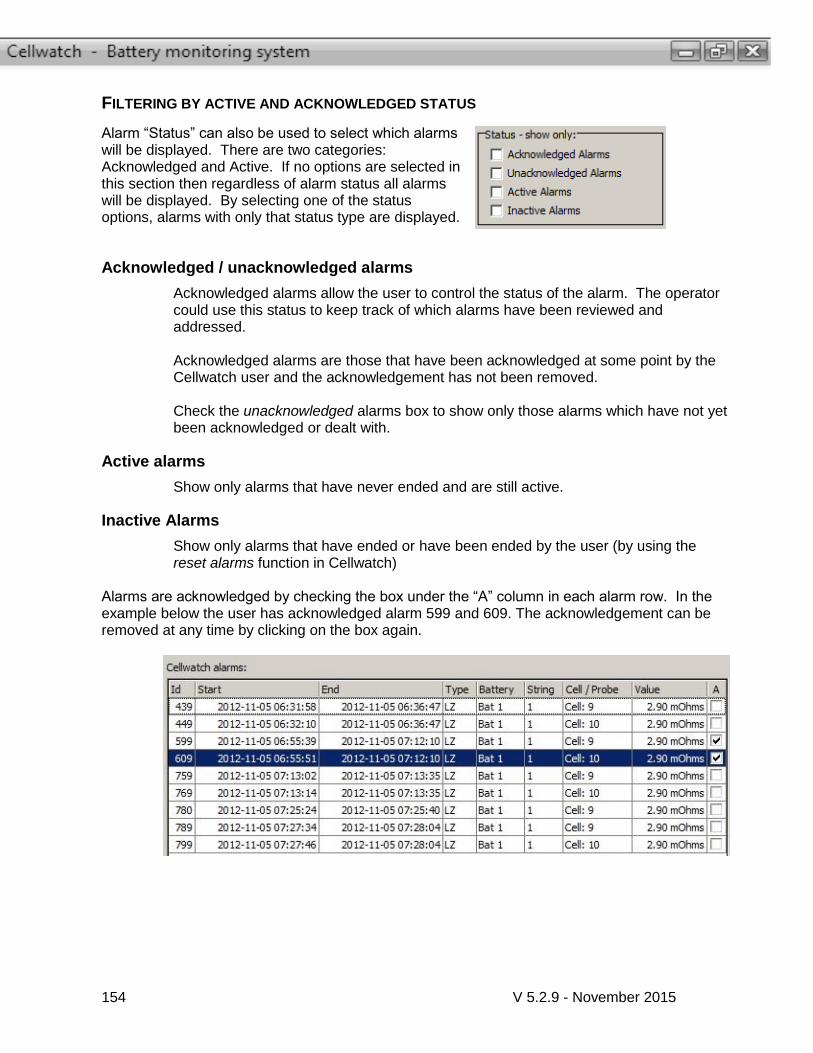
154 V 5.2.9 - November 2015
FILTERING BY ACTIVE AND ACKNOWLEDGED STATUS
Alarm “Status” can also be used to select which alarms will be displayed. There are two categories: Acknowledged and Active. If no options are selected in this section then regardless of alarm status all alarms will be displayed. By selecting one of the status options, alarms with only that status type are displayed.
Acknowledged / unacknowledged alarms
Acknowledged alarms allow the user to control the status of the alarm. The operator could use this status to keep track of which alarms have been reviewed and addressed. Acknowledged alarms are those that have been acknowledged at some point by the Cellwatch user and the acknowledgement has not been removed. Check the unacknowledged alarms box to show only those alarms which have not yet been acknowledged or dealt with.
Active alarms
Show only alarms that have never ended and are still active.
Inactive Alarms
Show only alarms that have ended or have been ended by the user (by using the reset alarms function in Cellwatch)
Alarms are acknowledged by checking the box under the “A” column in each alarm row. In the example below the user has acknowledged alarm 599 and 609. The acknowledgement can be removed at any time by clicking on the box again.

V4
FILTERING BY BATTERY, STRING AND CELL
The source control panel (right) is provided to display a particular battery, string, cell or combinations of the subset of the batteries being monitored. This panel works like the controls for the Cellwatch history view tool. By clicking on any of the available battery assets the user controls which battery string and jars to include in the display.
REFRESHING TO VIEW NEW ALARMS
In order to view new alarms as they are generated, click the Refresh button in the Data Manager window. Active alarms are shown in red until they end.
Once an alarm has ended the end date and time are recorded and the red background shading will be removed.

156 V 5.2.9 - November 2015
EXPORTING DATA TO A CSV FORMAT FILE
The new export feature allows the user to export alarm data as a CSV file to create a report or other data analysis. To export data:
Step 1 Click on “File” followed by “Export As CSV”.
Step 2 Confirm the export by clicking OK to the on screen dialog.
Step 3 When prompted, enter a file name and location for the CSV data file. There will be no confirmation on successful export.
BACKUP AND/OR CLEAR DATABASE
Users can create a copy or backup of the existing database by right clicking the appserver taskbar icon near the system clock and selecting ‘Backup Database’. This will generate a backup database for technical support or historical purposes. Users can clear the database and reset all alarm notifications by selecting ‘Clear Database’. This function is password protected and will require the deafcat password to operate. Once run all past documented alarm events will be cleared and the database will start with no events. This will not remove discharge files, simply the alarm events list.

V4
SOFTWARE: I WANT TO…
… STOP THE INITIAL OHMIC VALUE SCAN.
By default a voltage and an ohmic value scan will take place when a sytem first starts.
To cancel the start-up ohmic value scan, the Esc (escape) key can be pressed to cancel the scan. Once stopped, the software will cancel the scan for all remaining cells and the data will not be saved.
… RUN THE MONITORING SYSTEM ONCE AND LOOK AT THE DATA.
The default setting in the application is for the system to start operating with a complete system voltage read followed by an ohmic value read. Once the system is started, the status window will indicate what is currently happening in the program.
The status window first indicates a voltage reading taking place. All the visible cell depictions turn to yellow and in blocks of four, they will become green unless a depiction turns red indicating an alarm failure.
Upon the completion of a voltage reading, the system commences an ohmic value reading.
When the ohmic value measurement is completed the white status box at the top of the screen will indicate that the system is running by displaying the time and say that it is currently scanning . Current and temperature are scanned continuously, as fast as the system will allow, but always in the background. If all cells or jars measured correctly, all cell depictions will be green.
At this point cell or string data can be accessed using the left mouse button on either the string or cell depictions.
… CHANGE THE CONFIGURATION
Configuration files can be modified, but great care should be taken when doing so. The easiest method is to rebuild the configuration file using the Configuration Builder. This can be done quickly and easily if the user has a good working knowledge of the Cellwatch installation; for instance, knowing which control unit is monitoring which batteries and what order to build the configuration.
If this information is not available, users can modify the configuration file within Cellwatch, but again great care should be taken as this can alter and even compromise the Cellwatch configuration file which can disable the battery monitoring system.
When in doubt, contact your installer for assistance in modifying the configuration file.
A configuration change may be required if the user re-names any of the battery hardware to which the system is connected or if a battery string is added or removed from the existing configuration.
Great care needs to be taken when altering configuration data, as it is possible to corrupt or damage the configuration file and disable the battery monitoring system.

158 V 5.2.9 - November 2015
Areas that the user can alter moderately easily….
The names of the batteries displayed on the screen.
The names of the strings displayed on the screen.
Areas that the user can alter with support from your Cellwatch supplier….
Changes in architecture of the battery, i.e. adding or removing cells, batteries, or strings from the monitored configuration.
Areas the user should never try to alter….
The computer generated area on the left of the configuration grid. The first 6 columns colored grey are locked and cannot be edited.
The next 6 columns, titled CT to HY should not be altered except under guidance from your installer or supplier.
The areas shown in the screen shot of the configuration grid which is shaded defines the actual hardware architecture of the Cellwatch system itself and should never be altered. A window lock is positioned so that the top row remains on the screen at all times and the first six columns are always displayed. This window lock cannot be changed.
The data in the columns headed Battlbl, Strlbl, & Cellbl to the right of the shaded area defines the names that appear on screen for the battery itself, its strings and each cell, jar or mono-bloc appearing on screen. The user can alter these with care.
The screen shot above shows a 3 battery system (Alpha, Beta & Gamma) where the first battery has 2 strings (Left & Right), while the other batteries have 1 string each (North & South). All 4 current and temperature sensors are utilized. These would appear on screen as follows ……
DON’T FORGET – if you change the configuration file you may corrupt your History file. Adding extra hardware does not guarantee that you will capture the measurements in History. If in doubt – rename the History file so a new one is started.

V4
… REVIEW THE DATA FROM THE SYSTEM ACROSS A NETWORK.
Data files can be read off-line from the Battery Monitoring operation of the BMU. Copies of the *.his and *.dis files can be copied to another machine and viewed with a copy of the File Viewer or the Cellwatch Demo software.
Always copy the *.his file to a local directory for viewing. This helps ensure that you back up your battery data and secondly gives you access to the data when you are not on the same network as the iBMU.
If File Viewer is installed on a laptop or desktop system, the files can be opened simply by double clicking on the file. If you are using the Cellwatch Demo software we recommend running a copy of the demo software in the working directory of the files for quicker access.
Remote Desktop can be used to view live data as it occurs on the screen of the iBMU. Again, a network adapter or modem will need to be installedLastly, data can be reviewed from several different methods. They are:
Remote Desktop
Webpage interface (discharge and history files are located at the bottom of every page)
Modbus TCP/IP
SNMP
Cellwatch.net (online backup/data restore feature) – this is a subscription service
… RECEIVE OHMIC VALUE ALARM NOTIFICATIONS LATER IN THE WORKING DAY (I.E. DELAY THE OHMIC VALUE SCAN)…
The ohmic value scan normally runs at midnight. When the ohmic value passes the alarm criteria Cellwatch will notify the user. We understand that users may not like to learn that a jar has passed from 3.99 milli-ohms to 4.01 milli-ohms at midnight.
A feature has been built into Cellwatch which allows the user or installer to delay the first ohmic value scan of the day to any time later in the day (defined in minutes). To do this, determine what time you want the scan to take place (say 8:15 am) and convert that to minutes delay past midnight. With Cellwatch stopped and closed, open the cellwatch.ini file and enter the delay in minutes at the end of the line Minutes into day for scan =
Once completed, reopen Cellwatch. If a number is used larger than 1,440 (the number of minutes in a day) then Cellwatch will be delayed into the following day.
… BACK-UP MY DATA

160 V 5.2.9 - November 2015
It is important that data is backed up regularly to avoid loss of important historical information and to ensure that the configuration files are recoverable in the unlikely event of a hardware system failure.
If a network is available, the contents of the working directory c:/program files/cellwatch should be copied daily to a second machine’s archival area on the network. If the machine is being used standalone, then the *.cfg, *.dis, *.log & *.his files alone can be copied to back-up media such as a USB drive.

V4
SOFTWARE: OPERATION AND SET-UP OF ALARM FUNCTIONS
Introduction
Battery powered UPS systems rely upon the integrity of the batteries to be able to support the UPS when utility power fails. Therefore control circuits in the UPS monitor the overall voltage on the battery and try to maintain this voltage at the defined ‘float charge’ voltage. With regular maintenance of the UPS, these systems can generally be relied upon to maintain the overall string or battery voltage within defined limits. Most UPSs have the facility to indicate locally and remotely, if the overall battery voltage cannot be maintained within the defined range.
Unfortunately, this level of control and indication cannot show if individual elements (blocs) of the battery are performing poorly but only string level information. To obtain this greater level of information requires a battery monitoring system.
Cellwatch™ provides the means to comprehensively monitor the condition of each bloc in a battery system by regularly monitoring the voltage and ohmic value of the blocs or jars. It not only presents the user with snapshot information on the status of each bloc, but also provides access to historical data for these blocs.
Because of the level of detail available from the system, and because battery faults have varying degrees of significance, Cellwatch™ is designed to be used in an interactive manner. The predominant output from Cellwatch™ is the visual display.
The graphical user interface presents a simple way of determining the status of the monitored blocs, and it also gives summary information at string and battery level.
Alarm Indication Philosophy and Implementation in Cellwatch™
The alarm notification philosophy adopted in Cellwatch™ compliments the monitoring philosophy, by comparing individual bloc parameters to their associated alarm level settings. Any excursions outside the defined limits are then highlighted graphically for the user.
The parameters that are monitored against defined alarm levels are:-
Bloc (or jar) and String Voltage – upper & lower voltage limits are specified
Bloc (or jar) Ohmic value – upper & lower ohmic value limits are specified
Temperature - upper & lower temperature limits are specified
String Current - upper & lower string current limits can be specified
String Voltage – upper and lower string voltage limits can be specified
String Ripple Voltage (Ext. Feature) - upper string ripple voltage limits can be specified
String Recharge Current – lower limit or minimum current required for detecting recharge
current can be specified
These seven settings are shown in the ‘Edit global alarm settings’ dialogue box illustrated above:-
If ANY of the monitored values drift outside the defined alarm levels, an alarm condition will be indicated.

162 V 5.2.9 - November 2015
For example, if the voltage or ohmic value on any one bloc should go higher than the High Limit OR Lower than the Low Limit, then this will be indicated by the bloc depiction turning from GREEN to RED. At the same time, the indicator on the tab for the String and Battery that contains this bloc, will change from GREEN to RED, and the dry contact associated with Voltage or ohmic value, will be activated.
The purpose of this philosophy is to alert the operator of the battery system, to a potential problem that requires further investigation. To gain more information about the cause of the alarm requires the operator to interrogate the Cellwatch™ system – either locally or remotely.
The benefit of this detail approach over the more global ‘overall string’ approach is that the operator is encouraged to ascertain the nature and severity of the problem, rather than (perhaps) dismissing it as inconsequential.
SETTING THE ALARM LEVELS.
Temperature
This is the easiest alarm to set. The standard operating temperature for a lead acid battery is 25ºC (77ºF). For every 8ºC (15ºF) increase in temperature the battery can experience a 50% drop in life expectancy. Similarly the performance measured as a percentage of available capacity falls off rapidly as the temperature is reduced. At 10ºC (50ºF), battery performance is down to 85% to 90% compared to that available at 25ºC.
Therefore both upper and lower temperature alarm limits should be programmed in Cellwatch and both manufacturer’s specifications as well as the planned capacity and capability of any temperature/environmental control systems should be taken into consideration. Cellwatch can operate either in Celsius or Fahrenheit depending on what the users has selected on the desktop. By default all temperature readings are recorded as Celsius and are converted to Fahrenheit when a user views a history file.
DCM Temperature (Requires DCM 5 T)
Cellwatch 4.2 provides the feature of temperature probe readings on the sense wires for each channel measured. The temperature sensors on the DCM 5 are connected to the negative post along with the sense wire for voltage and ohmic readings. Post temperatures are recorded for each cell/jar and therefore each cell/jar will respond independently to the temperature alarm settings. The temperature alarms will trigger according to the alarm value defined in the String/Battery/Global settings. This means the temperature alarm may be active for an individual or a subset of jars without the string or ambient alarm activating. This alarm value is vital for providing Thermal Runaway detection in an open rack environment where the temperature of each jar needs to be individually monitored.
Current
The standard Cellwatch current probe can measure up to 1000 amps DC. The current probe is capable of withstanding 1,500 amps before saturation. Attempting to measure low charge currents below 10 amps accurately is almost impossible with such a wide range device.
Discharge
We recommend setting the “Discharge greater than” value to approximately ½ the actual load current of the string. This value is used to initiate the discharge scan routine. If the minimum maintained current conditions defined in the cellwatch.ini file (default value is 5 seconds) the discharge alarm will be initiated and the resulting discharge file will be saved. The value should
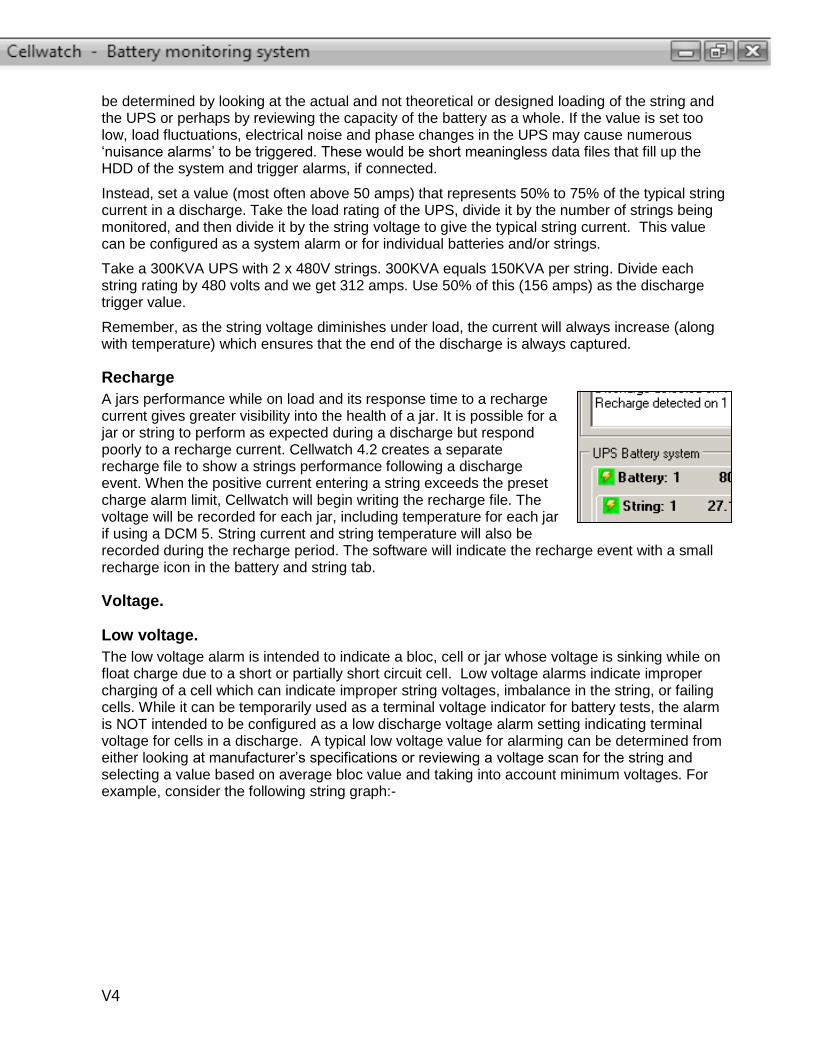
V4
be determined by looking at the actual and not theoretical or designed loading of the string and the UPS or perhaps by reviewing the capacity of the battery as a whole. If the value is set too low, load fluctuations, electrical noise and phase changes in the UPS may cause numerous ‘nuisance alarms’ to be triggered. These would be short meaningless data files that fill up the HDD of the system and trigger alarms, if connected.
Instead, set a value (most often above 50 amps) that represents 50% to 75% of the typical string current in a discharge. Take the load rating of the UPS, divide it by the number of strings being monitored, and then divide it by the string voltage to give the typical string current. This value can be configured as a system alarm or for individual batteries and/or strings.
Take a 300KVA UPS with 2 x 480V strings. 300KVA equals 150KVA per string. Divide each string rating by 480 volts and we get 312 amps. Use 50% of this (156 amps) as the discharge trigger value.
Remember, as the string voltage diminishes under load, the current will always increase (along with temperature) which ensures that the end of the discharge is always captured.
Recharge
A jars performance while on load and its response time to a recharge current gives greater visibility into the health of a jar. It is possible for a jar or string to perform as expected during a discharge but respond poorly to a recharge current. Cellwatch 4.2 creates a separate recharge file to show a strings performance following a discharge event. When the positive current entering a string exceeds the preset charge alarm limit, Cellwatch will begin writing the recharge file. The voltage will be recorded for each jar, including temperature for each jar if using a DCM 5. String current and string temperature will also be recorded during the recharge period. The software will indicate the recharge event with a small recharge icon in the battery and string tab.
Voltage.
Low voltage.
The low voltage alarm is intended to indicate a bloc, cell or jar whose voltage is sinking while on float charge due to a short or partially short circuit cell. Low voltage alarms indicate improper charging of a cell which can indicate improper string voltages, imbalance in the string, or failing cells. While it can be temporarily used as a terminal voltage indicator for battery tests, the alarm is NOT intended to be configured as a low discharge voltage alarm setting indicating terminal voltage for cells in a discharge. A typical low voltage value for alarming can be determined from either looking at manufacturer’s specifications or reviewing a voltage scan for the string and selecting a value based on average bloc value and taking into account minimum voltages. For example, consider the following string graph:-

164 V 5.2.9 - November 2015
This is a typical string voltage graph and shows an average voltage of 13.47 volts – a per cell value of 2.25 volts. Manufacturers such as C&D Technology recommend a low voltage limit of 2.16 volts per cell or 4% drop in voltage. Therefore selecting a voltage level of 4% below this average voltage (12.93V) would provide good voltage alarm sensitivity while not presently causing an alarm trigger (in the above example the present lowest voltage is shown as 13.11v).
High Voltage.
VRLA jars or blocs can develop high float voltages prior to failure due to open circuit or partially open circuit cells, although this is seen less often these can be very damaging failure mechanisms. Manufacturers may recommend a figure as high as 9% over average as an indicator of problems. For charging purposes, we recommend a number based upon 105% of average value to pick up high float values while still avoiding false alarms.
Most manufacturers will recommend a maximum float voltage of 2.26 volts per cell. Follow manufacturer recommendations for setting a high float voltage. It is not recommended to set the alarm limit to the equalization voltage (typically 2.3 volts per cell) as equalization settings are typically temporary.
Ripple Voltage (Requires DCM 5 - Extended Feature)
High ripple voltages can indicate that the UPS has failing components. Large ripple levels can cause damage to a battery over time. Some batteries may respond different than others to high ripple voltages. Many manufacturers and some standards bodies recommend a maximum ripple voltage of .5% of the output voltage of the UPS. So for a 540 DC Float Voltage, the recommended AC ripple alarm would be 2.7 Volts. Little to no ripple voltage is always preferred for the DC battery.
As an extended feature, this feature requires both DCM 5 and an activation code.

V4
String Voltage
A string’s overall voltage can be an indicator of voltage imbalance in the string or improper settings on the UPS charger. String level high and low voltage alarms allow for warning based solely on the charge status of string. This can help prevent overcharge and undercharge situations. Small increases of voltage on individual jars may not trigger a per cell/jar alarm. However, the change in overall string voltage can be identified independently and corrective action taken before the battery is damaged.
Alarming in Constant Voltage Scanning mode
Because cells can quickly change in voltage by several millivolts, a new alarming algorithm has been introduced when in constant voltage scan mode. A cell must remain above the alarm threshold for 5 scans (default setting) before an alarm is considered active. During this qualification period, the cell will remain green but the hover hint will indicate a delay alarm is about to occur. Users can see the delayed alarm status (via the hover hint), but the log file, emails and relays will not be triggered until the 5 scan threshold has been passed. The same logic applies when an alarm clears and the cell transitions from the alarmed (red) back to the non-alarmed (green) state.
Ohmic Value
Ohmic value alarms indicate changes occurring within a cell. There are many issues that can cause changes within the ohmic value of a monitored point. If an ohmic value issue is identified, first check the link and verify the torque of the connection. If the ohmic value does not change after the torques are verified, then the cause is likely due to a change within the cell. Changes can be attributed to micro-fractures within the cell, corrosion of the grid, loss of electrolyte, a decreased reactive surface area, or a number of other issues.
High ohmic value
High ohmic value (or impedance or resistance) is the best and most important indicator of battery health. Generally the ohmic value will rise before the float voltage begins to deteriorate; the two changes often (but not always) go hand in hand.
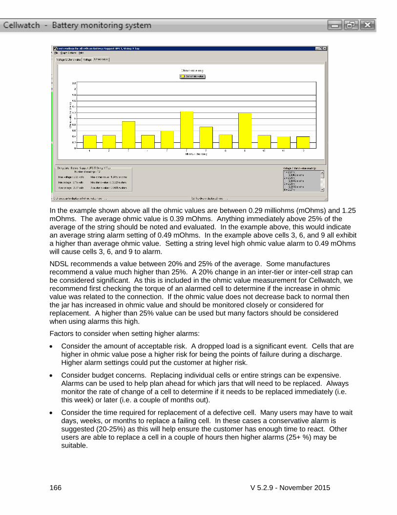
166 V 5.2.9 - November 2015
In the example shown above all the ohmic values are between 0.29 milliohms (mOhms) and 1.25 mOhms. The average ohmic value is 0.39 mOhms. Anything immediately above 25% of the average of the string should be noted and evaluated. In the example above, this would indicate an average string alarm setting of 0.49 mOhms. In the example above cells 3, 6, and 9 all exhibit a higher than average ohmic value. Setting a string level high ohmic value alarm to 0.49 mOhms will cause cells 3, 6, and 9 to alarm.
NDSL recommends a value between 20% and 25% of the average. Some manufactures recommend a value much higher than 25%. A 20% change in an inter-tier or inter-cell strap can be considered significant. As this is included in the ohmic value measurement for Cellwatch, we recommend first checking the torque of an alarmed cell to determine if the increase in ohmic value was related to the connection. If the ohmic value does not decrease back to normal then the jar has increased in ohmic value and should be monitored closely or considered for replacement. A higher than 25% value can be used but many factors should be considered when using alarms this high.
Factors to consider when setting higher alarms:
Consider the amount of acceptable risk. A dropped load is a significant event. Cells that are higher in ohmic value pose a higher risk for being the points of failure during a discharge. Higher alarm settings could put the customer at higher risk.
Consider budget concerns. Replacing individual cells or entire strings can be expensive. Alarms can be used to help plan ahead for which jars that will need to be replaced. Always monitor the rate of change of a cell to determine if it needs to be replaced immediately (i.e. this week) or later (i.e. a couple of months out).
Consider the time required for replacement of a defective cell. Many users may have to wait days, weeks, or months to replace a failing cell. In these cases a conservative alarm is suggested (20-25%) as this will help ensure the customer has enough time to react. Other users are able to replace a cell in a couple of hours then higher alarms (25+ %) may be suitable.
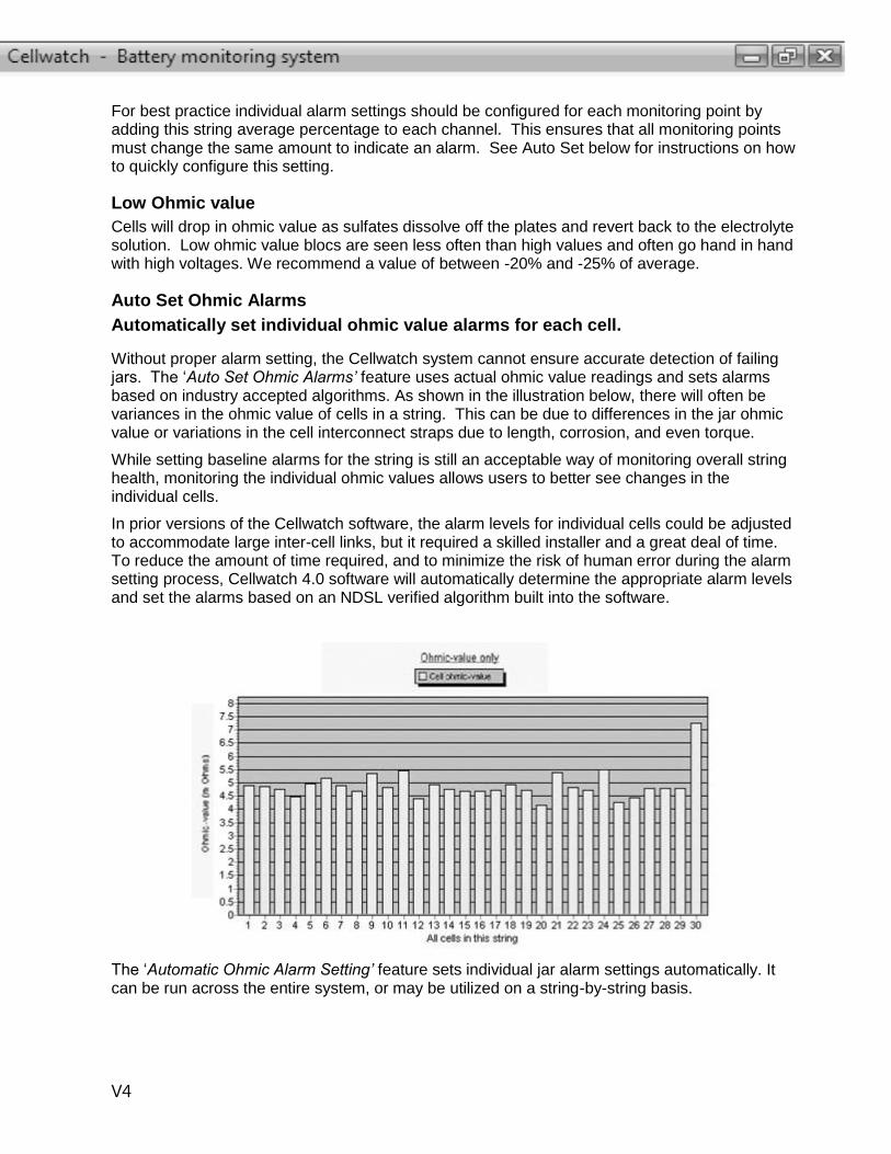
V4
For best practice individual alarm settings should be configured for each monitoring point by adding this string average percentage to each channel. This ensures that all monitoring points must change the same amount to indicate an alarm. See Auto Set below for instructions on how to quickly configure this setting.
Low Ohmic value
Cells will drop in ohmic value as sulfates dissolve off the plates and revert back to the electrolyte solution. Low ohmic value blocs are seen less often than high values and often go hand in hand with high voltages. We recommend a value of between -20% and -25% of average.
Auto Set Ohmic Alarms
Automatically set individual ohmic value alarms for each cell.
Without proper alarm setting, the Cellwatch system cannot ensure accurate detection of failing jars. The ‘Auto Set Ohmic Alarms’ feature uses actual ohmic value readings and sets alarms based on industry accepted algorithms. As shown in the illustration below, there will often be variances in the ohmic value of cells in a string. This can be due to differences in the jar ohmic value or variations in the cell interconnect straps due to length, corrosion, and even torque.
While setting baseline alarms for the string is still an acceptable way of monitoring overall string health, monitoring the individual ohmic values allows users to better see changes in the individual cells.
In prior versions of the Cellwatch software, the alarm levels for individual cells could be adjusted to accommodate large inter-cell links, but it required a skilled installer and a great deal of time. To reduce the amount of time required, and to minimize the risk of human error during the alarm setting process, Cellwatch 4.0 software will automatically determine the appropriate alarm levels and set the alarms based on an NDSL verified algorithm built into the software.
The ‘Automatic Ohmic Alarm Setting’ feature sets individual jar alarm settings automatically. It can be run across the entire system, or may be utilized on a string-by-string basis.
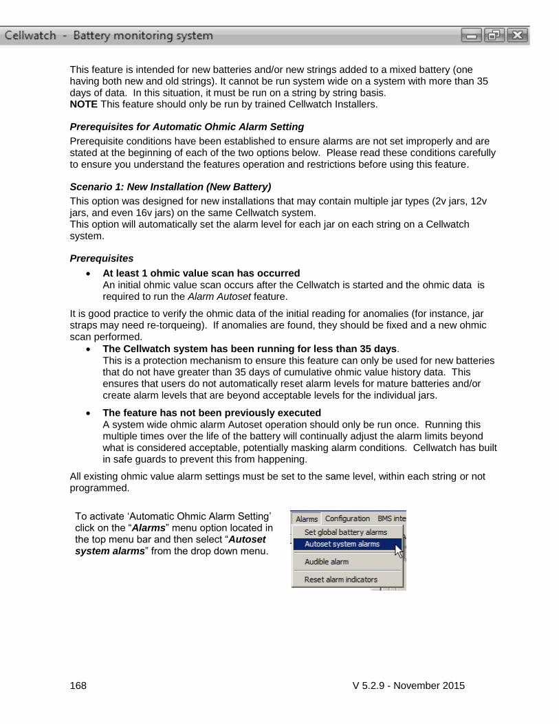
168 V 5.2.9 - November 2015
This feature is intended for new batteries and/or new strings added to a mixed battery (one having both new and old strings). It cannot be run system wide on a system with more than 35 days of data. In this situation, it must be run on a string by string basis. NOTE This feature should only be run by trained Cellwatch Installers.
Prerequisites for Automatic Ohmic Alarm Setting
Prerequisite conditions have been established to ensure alarms are not set improperly and are stated at the beginning of each of the two options below. Please read these conditions carefully to ensure you understand the features operation and restrictions before using this feature.
Scenario 1: New Installation (New Battery)
This option was designed for new installations that may contain multiple jar types (2v jars, 12v jars, and even 16v jars) on the same Cellwatch system. This option will automatically set the alarm level for each jar on each string on a Cellwatch system.
Prerequisites
At least 1 ohmic value scan has occurred An initial ohmic value scan occurs after the Cellwatch is started and the ohmic data is required to run the Alarm Autoset feature.
It is good practice to verify the ohmic data of the initial reading for anomalies (for instance, jar straps may need re-torqueing). If anomalies are found, they should be fixed and a new ohmic scan performed.
The Cellwatch system has been running for less than 35 days. This is a protection mechanism to ensure this feature can only be used for new batteries that do not have greater than 35 days of cumulative ohmic value history data. This ensures that users do not automatically reset alarm levels for mature batteries and/or create alarm levels that are beyond acceptable levels for the individual jars.
The feature has not been previously executed A system wide ohmic alarm Autoset operation should only be run once. Running this multiple times over the life of the battery will continually adjust the alarm limits beyond what is considered acceptable, potentially masking alarm conditions. Cellwatch has built in safe guards to prevent this from happening.
All existing ohmic value alarm settings must be set to the same level, within each string or not programmed.
To activate ‘Automatic Ohmic Alarm Setting’ click on the “Alarms” menu option located in the top menu bar and then select “Autoset system alarms” from the drop down menu.
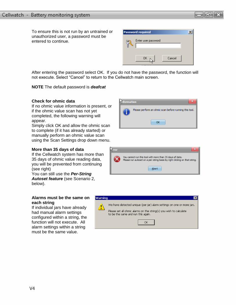
V4
To ensure this is not run by an untrained or unauthorized user, a password must be entered to continue.
After entering the password select OK. If you do not have the password, the function will not execute. Select “Cancel” to return to the Cellwatch main screen. NOTE The default password is deafcat
Check for ohmic data If no ohmic value information is present, or if the ohmic value scan has not yet completed, the following warning will appear. Simply click OK and allow the ohmic scan to complete (if it has already started) or manually perform an ohmic value scan using the Scan Settings drop down menu.
More than 35 days of data If the Cellwatch system has more than 35 days of ohmic value reading data, you will be prevented from continuing (see right) You can still use the Per-String Autoset feature (see Scenario 2, below).
Alarms must be the same on each string If individual jars have already had manual alarm settings configured within a string, the function will not execute. All alarm settings within a string must be the same value.

170 V 5.2.9 - November 2015
Check for anomalies Finally, the system will check for any jar readings that deviate from the string average. This verifies that anomalous conditions (a poorly torqued tab or a failing jar) are not about to be masked by the alarm Autoset functionality.
HINT Use the Save to Desktop button to export a checklist of the anomalous jars for investigation and resolution prior to continuing with this feature.
If all of the prerequisite conditions have been met the following prompt will appear. The default setting is 25% above the string latest ohmic value recorded by the Cellwatch system. This setting can be changed by unchecking the ‘Use default values’ box. For new strings, Cellwatch recommends an alarm setting of 20% to 25% of the original ohmic value of the cell.
NOTE: When using Cellwatch on older strings, it is recommended to use a lower percentage for calculating alarm levels. A more acceptable value would be 10% or lower depending on the age of the string.
Press ‘Continue’ to set the alarms for all battery strings currently configured on the Cellwatch system.
Enable custom alarm percentage
Uncheck this box to input a custom alarm percentage.
Custom alarm percentage
Customize the alarm threshold in aging cells where higher
sensitivity is needed.

V4
All alarms for all battery strings will be programmed at the calculated level, using the selected percentage above the current measured ohmic reading. Once the alarms have been set a dialog will appear informing the user that the alarm levels will be automatically recalculated in 35 days’ time (right).
Recalculation after 35 days
The Cellwatch system will count 35 days and then the alarms will automatically be recalculated without user intervention. During the first 30 days of a battery installation it is not uncommon for cell ohmic values to drop slightly due to the charge process and settling of the cells. This new baseline ohmic value is taken into effect and recalculated automatically without user intervention. After 35 days, the Cellwatch system will automatically recalculate the ohmic alarm settings for all jars on all strings based on the new measurements.
IMPORTANT This feature will not run on any strings on which there was an ohmic alarm during this 35 day time period (or if there are active ohmic alarms). The Cellwatch system will inform the user if any alarms are present and will record this information to the Cellwatch log file.
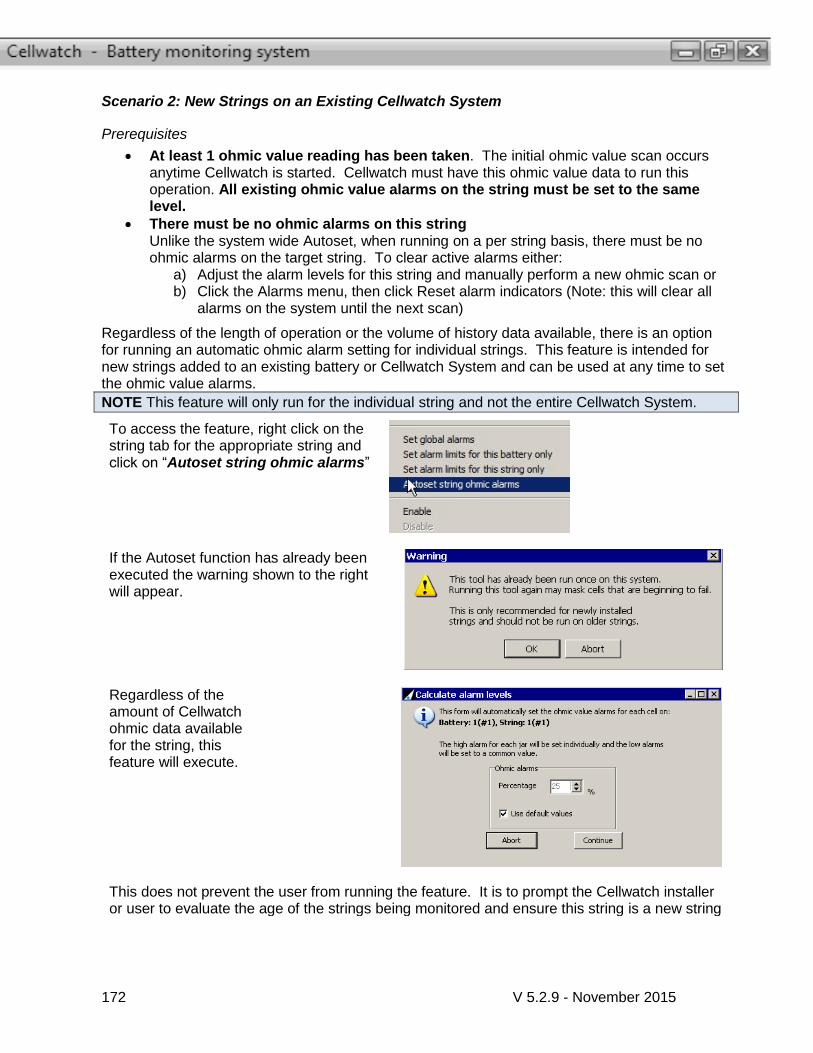
172 V 5.2.9 - November 2015
Scenario 2: New Strings on an Existing Cellwatch System
Prerequisites
At least 1 ohmic value reading has been taken. The initial ohmic value scan occurs anytime Cellwatch is started. Cellwatch must have this ohmic value data to run this operation. All existing ohmic value alarms on the string must be set to the same level.
There must be no ohmic alarms on this string Unlike the system wide Autoset, when running on a per string basis, there must be no ohmic alarms on the target string. To clear active alarms either:
a) Adjust the alarm levels for this string and manually perform a new ohmic scan or b) Click the Alarms menu, then click Reset alarm indicators (Note: this will clear all
alarms on the system until the next scan)
Regardless of the length of operation or the volume of history data available, there is an option for running an automatic ohmic alarm setting for individual strings. This feature is intended for new strings added to an existing battery or Cellwatch System and can be used at any time to set the ohmic value alarms.
NOTE This feature will only run for the individual string and not the entire Cellwatch System.
To access the feature, right click on the string tab for the appropriate string and click on “Autoset string ohmic alarms”
If the Autoset function has already been executed the warning shown to the right will appear.
Regardless of the amount of Cellwatch ohmic data available for the string, this feature will execute.
This does not prevent the user from running the feature. It is to prompt the Cellwatch installer or user to evaluate the age of the strings being monitored and ensure this string is a new string
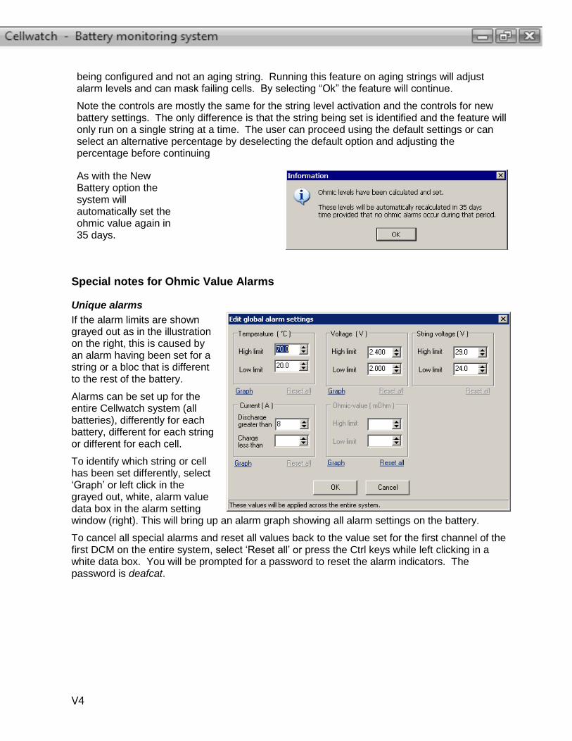
V4
being configured and not an aging string. Running this feature on aging strings will adjust alarm levels and can mask failing cells. By selecting “Ok” the feature will continue.
Note the controls are mostly the same for the string level activation and the controls for new battery settings. The only difference is that the string being set is identified and the feature will only run on a single string at a time. The user can proceed using the default settings or can select an alternative percentage by deselecting the default option and adjusting the percentage before continuing
As with the New Battery option the system will automatically set the ohmic value again in 35 days.
Special notes for Ohmic Value Alarms
Unique alarms
If the alarm limits are shown grayed out as in the illustration on the right, this is caused by an alarm having been set for a string or a bloc that is different to the rest of the battery.
Alarms can be set up for the entire Cellwatch system (all batteries), differently for each battery, different for each string or different for each cell.
To identify which string or cell has been set differently, select ‘Graph’ or left click in the grayed out, white, alarm value data box in the alarm setting window (right). This will bring up an alarm graph showing all alarm settings on the battery.
To cancel all special alarms and reset all values back to the value set for the first channel of the first DCM on the entire system, select ‘Reset all’ or press the Ctrl keys while left clicking in a white data box. You will be prompted for a password to reset the alarm indicators. The password is deafcat.
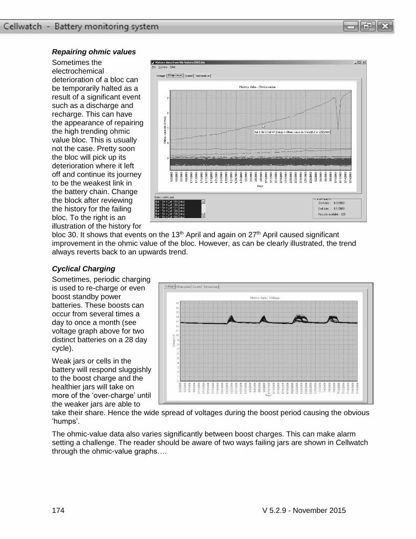
174 V 5.2.9 - November 2015
Repairing ohmic values
Sometimes the electrochemical deterioration of a bloc can be temporarily halted as a result of a significant event such as a discharge and recharge. This can have the appearance of repairing the high trending ohmic value bloc. This is usually not the case. Pretty soon the bloc will pick up its deterioration where it left off and continue its journey to be the weakest link in the battery chain. Change the block after reviewing the history for the failing bloc. To the right is an illustration of the history for bloc 30. It shows that events on the 13th April and again on 27th April caused significant improvement in the ohmic value of the bloc. However, as can be clearly illustrated, the trend always reverts back to an upwards trend.
Cyclical Charging
Sometimes, periodic charging is used to re-charge or even boost standby power batteries. These boosts can occur from several times a day to once a month (see voltage graph above for two distinct batteries on a 28 day cycle).
Weak jars or cells in the battery will respond sluggishly to the boost charge and the healthier jars will take on more of the ‘over-charge’ until the weaker jars are able to take their share. Hence the wide spread of voltages during the boost period causing the obvious ‘humps’.
The ohmic-value data also varies significantly between boost charges. This can make alarm setting a challenge. The reader should be aware of two ways failing jars are shown in Cellwatch through the ohmic-value graphs….

V4
In the example shown above, failure of the jar can be predicted one month or more before failure by observation of both the slope of the ohmic value increase and by the high level the ohmic value reached just before the recharge cycle started.
In this more subtle example, the overall slope of the ohmic-value is increasing but it is harder to detect at this early stage. Careful and frequent review of the data is required. The alarm criteria however is very helpful and should be based on the ohmic value measured when the jar is on

176 V 5.2.9 - November 2015
charge (2.5 milli-ohms in the example above). If the upper ohmic value alarm limit is set to 120% of this value (3 milli-ohms), the alarm would be triggered during the end part of the non-charge period as the jar deteriorates. During or following a recharge the alarm setting may clear as the ohmic value falls within limits.
Conclusion: for periodic charge systems, set the upper ohmic-value alarm to 120% to 125% of the value measured while the jar is on charge.
Thermal Runaway
Cellwatch 4.1 introduced a new alarm setting in the Cellwatch system for Thermal Runaway detection and mitigation. This feature works alongside new hardware called the Thermal Runaway Controller (TRC). This controller introduces several new relays that can be integrated into a users’ battery system which can take a string offline if thermal runaway conditions persist for a defined period of time. Hardware installation instructions and relay configurations are described in the hardware section of this manual.
Conditions for Thermal Runaway
Heat is generated when the battery chemistry is in the recombination phase during a recharge cycle. When the cell/jar/battery is in the fully recombinant mode the excess energy is converted to heat. When a cell is able to dissipate this excessive heat into the environment and remain stable, thermal runaway will not be an issue. However, if the amount of heat generated exceeds the rate at which the jar dissipates heat into the environment, thermal runaway can occur. As the temperature rises, more current is required to maintain the float voltage increasing the heat dissipated by the already recombinant jar. The result is a continual increase in float current and temperature of the cell until thermal runaway occurs. The net effect of thermal runaway can be accelerated dry-out (predominantly flooded lead acid cells) and/or melting of the battery (predominantly VRLA cells).1
Measuring float current of each jar is the initial indicators that thermal runaway is could occur. Often times a string level measurement float current measurement is suitable to determine if thermal runway is possible. A by-product of increased float current is increased cell temperatures, as heat is dissipated and increased cell voltage. Cellwatch monitors both ambient or pilot cell temperatures and cell voltages for thermal runaway conditions.
To prevent thermal runaway the source of the float charge current must be removed. This is done by removing the string from operation, i.e. opening the battery string. It is recommended to monitor and remove each string independently. Strings should be isolated from other strings and not simply the UPS as the paralleled strings could continue to provide the float current continuing the generation of heat.
Configuring Thermal Runaway Protection
Thermal Runaway alarms are configured on a per string basis. Note that for thermal runaway settings to be accessible the string must be on a TRC. Thermal Runaway Alarm settings can be configured by right clicking on an eligible string and selecting Thermal Runaway Protection in the drop down menu. Once the string is configured you will note a shield icon on the string tab.
Setting Thermal Runaway alarms
Thermal events
1 IEEE Standard 1188-2005, Appendix C2 Thermal Runaway

V4
Alarm Settings
Shield Icons
Shield icons are only seen on strings with Thermal Runaway protection enabled. Users can right click on a string to determine if the string is available for Thermal Runaway protection. To activate this feature right click on the string tab and select the “Thermal Runaway Protection” option from the menu. The Thermal Settings (see the next section) will appear to enable or disable protection. The box to enable the feature must be selected followed by the selection of the cell voltage and string temperature.
Testing String Disconnect settings
This is an important part of every configuration where Thermal Runaway Protection is implemented. It is highly recommended that every system with thermal runaway protection be tested prior to commissioning a Cellwatch system for operation. This ensures that Cellwatch is in the best suited position to help mitigate, detect, and prevent a thermal event.
Using the ‘Test string disconnect’ allows users to verify that the relay circuit is configured correctly to remove a string from operation. Once activated, the relay tied to this physical string will be activated for 15 seconds. If configured properly to an external breaker, the string should be taken offline until manually reconnected.
To proceed with the test feature a password must be entered and the operator must manually proceed with the test as this could take an operational string offline. The user will be warned that actuating the relay will take a string offline.
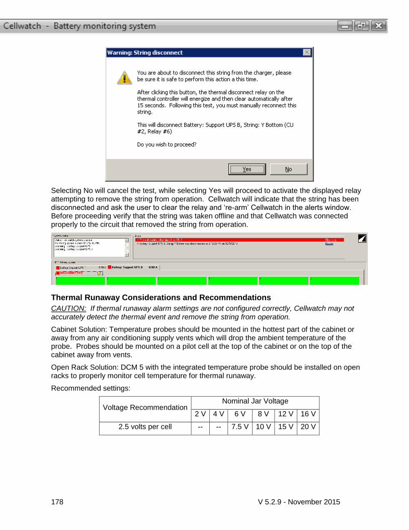
178 V 5.2.9 - November 2015
Selecting No will cancel the test, while selecting Yes will proceed to activate the displayed relay attempting to remove the string from operation. Cellwatch will indicate that the string has been disconnected and ask the user to clear the relay and ‘re-arm’ Cellwatch in the alerts window. Before proceeding verify that the string was taken offline and that Cellwatch was connected properly to the circuit that removed the string from operation.
Thermal Runaway Considerations and Recommendations
CAUTION: If thermal runaway alarm settings are not configured correctly, Cellwatch may not accurately detect the thermal event and remove the string from operation.
Cabinet Solution: Temperature probes should be mounted in the hottest part of the cabinet or away from any air conditioning supply vents which will drop the ambient temperature of the probe. Probes should be mounted on a pilot cell at the top of the cabinet or on the top of the cabinet away from vents.
Open Rack Solution: DCM 5 with the integrated temperature probe should be installed on open racks to properly monitor cell temperature for thermal runaway.
Recommended settings:
Voltage Recommendation Nominal Jar Voltage
2 V 4 V 6 V 8 V 12 V 16 V
2.5 volts per cell -- -- 7.5 V 10 V 15 V 20 V

V4
Cabinet Environment
Alarm Forced Air Environment (actively cooled cabinet)
Non-Forced Air Environment (passively cooled cabinet)
General Peak
Ambient
C F C F C / F
High Temp Alarm
Peak Ambient + 3
C
Peak Ambient + 8
F
Peak Ambient + 4 C
Peak Ambient + 12 F
30 C / 86 F Thermal Runaway
Alarm
Peak Ambient + 8
C
Peak Ambient + 12
F
Peak Ambient + 10 C
Peak Ambient + 18 F
Open Rack Environment
Alarm Environment General Peak
Ambient
C F C / F
High Temp Alarm Peak Ambient + 3 C Peak Ambient + 8 F
30 C / 86 F Thermal Runaway Alarm
Peak Ambient + 8 C Peak Ambient + 12 F
Both a thermal warning voltage alarm and a thermal warning temperature alarm must occur before Cellwatch will begin a disconnection timer. Prior to this condition Cellwatch should have acknowledge high float voltage and high temperature alarms. Both a thermal warning high voltage must be detected on a cell and a thermal warning high string temperature must be detected on the same string for the thermal warning alarm to activate.
It is always recommended that high temperature alarms be lower than the thermal runaway alarm settings.
If not configured properly (i.e. the temperature probe is mounted to the wrong string) Cellwatch may not respond in proper time to prevent thermal runaway. Always verify that the probes and the alarm settings are set correctly before commissioning a system.
NOTE: Thermal runway conditions can occur due to improper charging schemes on any cell. For example, charging a 12 volt jar at 80 volts will cause thermal runaway faster than charging a jar floating at 14 volts. This is due to the amount of heat dissipated from the jar.
Preventing Thermal Runaway without the Thermal Runaway Controller
Users with properly configured alarm settings and that adequately monitor their Cellwatch system will identify characteristics of thermal runaway long before it ever becomes an issue. While thermal runaway could occur on any system, it is most likely to occur on systems where the battery is left unmonitored or where the battery monitoring system is ignored.
In these situations, customers using non-thermal controllers can still detect thermal runaway conditions however Cellwatch will not remove the string from operation or provide thermal alarm

180 V 5.2.9 - November 2015
notifications. Instead high voltage and temperature alarms will be detected. IFC 608.3 requires a listed device like Cellwatch to meet the specifications.
References
1 – Resistance recommendations see C&D Technology paper “Valve Regulated Lead Acid Battery” series, “Impedance and Conductance Testing” 41-7271 Rev 8.99.
2 – Float Voltage high and low limits see C&D Technology paper “Valve Regulated Lead Acid Battery” series, “Integrity Testing”. 41-7264 Rev 8/99.
3 – For upper temperature performance data see C&D Technology paper “Valve Regulated Lead Acid Battery” series, “Life Expectancy and Temperature” 41-7329 Rev 5.99
4 – For lower temperature performance data see C&D Technology paper “Valve Regulated Lead Acid Battery” series, “DYNASTY VRLA batteries Electrolyte Freeze Protection Testing” 41-7953 Rev 3.99

V4
SOFTWARE: COMMUNICATION
BUILDING MANAGEMENT SYSTEM (BMS) INTERFACE
The simple BMS Gateway allows the Battery Monitoring System software running on its iBMU to interface to a facility’s management and control software package using the iBMU’s RS232 port. Enabling this function allows the software to communicate via the serial port to an external computer system for reporting and further alarm functions.
To enable the BMS Gateway it is necessary to turn it on via the BMS Interface drop down menu. When either the Gateway is selected or a request made to change the port, a password is requested.
To turn off the Gateway, temporarily (until Cellwatch is restarted) select ‘Gateway Off’. To turn it off permanently, it is necessary to deselect the port via the Select Port function on the menu.
The gateway has 7 alarms and has a fixed baud rate of 9600 bps on a dedicated serial port.
Bit Meaning
1 True if any other alarms are set
2 Voltage alarm (string or cell)
3 Ohmic alarm
4 Current alarm (typically discharge)
5 Temperature alarm
6 General alarm
7 Comms alarm (i.e. CU did not respond to last query)
Requesting an ‘S’ on the serial port from the connected gateway device will provide a status update in a byte returned beginning with bit 1 through 7. Ex: ‘S’ could return o:1000100 which would indicate a temperature alarm.
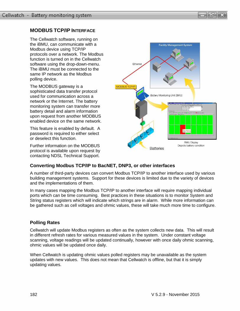
182 V 5.2.9 - November 2015
MODBUS TCP/IP INTERFACE
The Cellwatch software, running on the iBMU, can communicate with a Modbus device using TCP/IP protocols over a network. The Modbus function is turned on in the Cellwatch software using the drop-down-menu. The iBMU must be connected to the same IP network as the Modbus polling device.
The MODBUS gateway is a sophisticated data transfer protocol used for communication across a network or the Internet. The battery monitoring system can transfer more battery detail and alarm information upon request from another MODBUS enabled device on the same network.
This feature is enabled by default. A password is required to either select or deselect this function.
Further information on the MODBUS protocol is available upon request by contacting NDSL Technical Support.
Converting Modbus TCP/IP to BacNET, DNP3, or other interfaces
A number of third-party devices can convert Modbus TCP/IP to another interface used by various building management systems. Support for these devices is limited due to the variety of devices and the implementations of them.
In many cases mapping the Modbus TCP/IP to another interface will require mapping individual ports which can be time consuming. Best practices in these situations is to monitor System and String status registers which will indicate which strings are in alarm. While more information can be gathered such as cell voltages and ohmic values, these will take much more time to configure.
Polling Rates
Cellwatch will update Modbus registers as often as the system collects new data. This will result in different refresh rates for various measured values in the system. Under constant voltage scanning, voltage readings will be updated continually, however with once daily ohmic scanning, ohmic values will be updated once daily.
When Cellwatch is updating ohmic values polled registers may be unavailable as the system updates with new values. This does not mean that Cellwatch is offline, but that it is simply updating values.

V4
When polling via Modbus TCP/IP, either directly or by a converter (ex. BacNET to Modbus TCP/IP) the recommended polling rate is once per second with no more than a 100 register per request.
BROWSER INTERFACE
Cellwatch comes with an integral HTTP web interface that permits anyone on the user’s network to see the summarized results from the battery monitoring system. For this to operate Cellwatch must be connected to a Local Area Network and correctly configured on that network by the owner’s system administrator.
If the system administrator configures the monitoring system to be viewed across the Internet then Cellwatch data can be accessed from a standard web browser anywhere in the world. This access to Cellwatch is read only and cannot interfere with the operation of Cellwatch battery monitoring.
The webpage interface can be password protected which is enabled through the cellwatch.ini file. The webpage can also be moved from the default port 80 to another unused port by modifying the cellwatch.ini file.
Turning Web Browsing On.
As described in Chapter 3 under Drop Down Menus the web interface is turned on by checking the Browser Interface function in the BMS interface menu. This will cause the Cellwatch program to start and run a HTTP (hypertext transfer protocol) server hosted internally that serves a number of web pages from the software.
These pages are served from the software and are viewable on the Cellwatch iBMU by running the Microsoft Internet Explorer program and typing into the browser address bar http://localhost
The Pages
There are 5 pages served by the Cellwatch program. These are as follows:
System (http://localhost/system)
Battery (http://localhost/batteryN)
String (http://localhost/batteryN/stringN)
Discharges (http://localhost/discharges)
Logs (http://localhost/logs)
Where ‘N’ above is a numerical value that corresponds to the Cellwatch ID of each battery and string.

184 V 5.2.9 - November 2015
System Page.
The default (or system) page, served up when http://localhost is typed into the Cellwatch computer is an overview page that shows the key data of the monitored batteries.
The time and date shown in the top right hand band is the clock time on the Cellwatch iBMU when the page was served. To ensure the page always reflects recent data, the page auto refreshes every 10 seconds so this time should advance in 10 second intervals.
In the example shown above, CWICU0003 is the network name of the iBMU and is the default name of the computer. This name should be noted as this is the address of the system viewed across a network and is used by other machines on the network instead of localhost.
The information in the top half of the window is self-explanatory and is designed to provide a quick summary of system and alarm information. In addition it gives information on the last discharge that occurred on the system as well as access to the discharge file if created and information relating to the next planned measurement cycle.
Below this is the detail area providing both summary information for the individual batteries that make up the strings as well as hyperlinks to battery and string detail pages that are described below.
The last link on the page allows the browser access to download history files that have been created by Cellwatch.
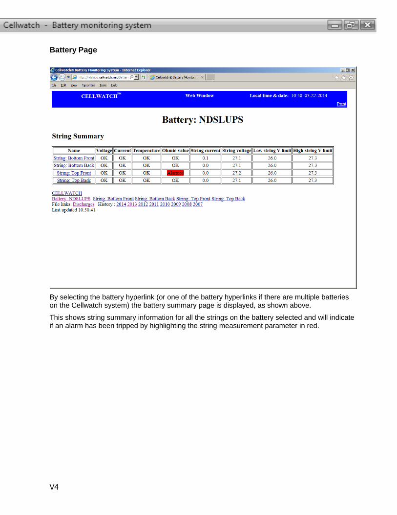
V4
Battery Page
By selecting the battery hyperlink (or one of the battery hyperlinks if there are multiple batteries on the Cellwatch system) the battery summary page is displayed, as shown above.
This shows string summary information for all the strings on the battery selected and will indicate if an alarm has been tripped by highlighting the string measurement parameter in red.

186 V 5.2.9 - November 2015
String Page
The string page provides the greatest degree of detail on the selected string by showing not only summary information at the top of the page but will also display all the cell’s individual measurement readings at the time of the last scan. In addition each individual alarm level is shown for temperature, ohmic value and voltage readings.
If at any time the Cellwatch battery monitoring system is not operating as expected or has been stopped. Warning messages will appear instead of the data window.
All string windows refresh every 60 seconds to ensure the user is viewing the latest data. In the string window, where the battery cell data extends beyond the window and a scroll bar is necessary, this may cause the data displayed to be repositioned each time it has been refreshed.

V4
Logs, discharges and history files.
Clicking on the History hyperlinks will download to the browser’s computer the selected file. This file can then be viewed in a spreadsheet program or another copy of the Cellwatch application.
Clicking on the ‘Discharges’ hyperlink will bring up a list-page of discharge files and their dates of creation. This list is limited to the most recent 30 files. Clicking on any discharge file hyperlink will download the file to the browser’s computer for viewing in a spreadsheet program or another copy of Cellwatch.
If the address http://localhost/logs is entered into browser address window then all the Cellwatch logs on the system are available for view. Each log, identified by its name and date and time of creation are presented for selection. Clicking on a log hyperlink opens the log in the browser window so that the events of that day can be reviewed in detail. To copy the log to the browser’s computer, right click the log hyperlink and select Save Target As from the browser’s menu. The default filename is ‘N.txt’ where N is the number of days old the file is. Hence today’s log-file will be called 0.txt.

188 V 5.2.9 - November 2015
SOFTWARE: QUICK REFERENCE
This section serves as a quick guide to discuss matters that are not covered in the Installation manual.
LICENSE AUTO-ACTIVATION
The iBMU arrives with an already activated version of Cellwatch. Cellwatch is licensed for that IBMU hardware only and cannot be transferred to another iBMU. While it may be possible to run Cellwatch on any other system, activation codes and licenses will not be distributed. Cellwatch suppliers only provide warranty on systems using the iBMU supplied.
License Activation Required: Extended Feature Sets
As extended features are released for the Cellwatch software. Some feature sets require newer hardware, while others unlock capabilities of existing hardware. To activate these features select Help > Feature Activation as shown below.
Once selected an extended feature activation window will appear. A randomly generated Cellwatch Product Code will appear which will be required as part of the activation process for extended features. Users must first order the feature from their NDSL reseller and provide the order key to NDSL Technical Support or enter it via the online website. Enter the activation code and click Activate.
If successfully activated, the advanced features will be available immediately.
THE IBMU
The iBMU that was supplied with your system has been optimized to operate the Battery Monitoring System. Due to OS licensing, other applications should NOT be run on the system. Only software that further secures the system (firewall, antivirus, etc…) may be installed. As these may conflict with resources required by the Cellwatch application, verify that these applications do not interfere with Cellwatch and its ability to collect battery data. The Cellwatch application can use large amounts of memory to handle and display the data that it collects which may slow the performance of the machine if other applications are also running.
Hard disk resource usage is relatively low due to the efficient use of archival space made by Cellwatch. Typically, Cellwatch will require the following hard disk space for any given system:-
Number of Cells For 30 days data For 1 year data
40 24 Kbytes 288 Kbytes
240 132 Kbytes 1.6 Mbytes
1000 0.5 Mbyte 6 Mbytes

V4
RESTORING CELLWATCH DATA
Data should be copied to an external location other than the iBMU hard drive. This can be done by backing up the Cellwatch working directory to a USB thumb drive or network drive. Alternately, the Cellwatch.net service can be used to back up the Cellwatch data from the iBMU. If Cellwatch data is corrupted, it is recommended to remove all corrupted Cellwatch data from the C:\Program Files\Cellwatch directory.
Restoring your backup data can be achieved by directly copying the contents of the backup directory to the C:\Program Files\Cellwatch directory. This will restore both the application program and the configuration file that defines the system configuration. Any history files (*.his) or discharge file (*.dis) may or may not be installed at the user’s discretion.
NOTE: Attempting to run the Cellwatch software on anything other than the iBMU will prompt for an activation code. The Cellwatch software is only licensed to run on the iBMU.
Re-running the Cellwatch application will cause the program to look for the original configuration file (batconfig.cfg). Any changes made to the configuration such as custom alarm settings will be lost unless they were saved to the backup destination. Similarly, any discharge or history data will be lost unless archived.
RESTORING A LOST CONFIGURATION FILE
Running the Cellwatch software will cause the application to look for a configuration file batconfig.cfg in its working directory. If the configuration file cannot be found Cellwatch will prompt the user to import a configuration file or to run a hardware detect to create a new basic configuration.
Restoring a Batconfig.cfg from a History (.his) or Discharge (.dis) file
A copy of the batconfig.cfg file is saved in the headers of the history (.his) or discharge (.dis) files. Always use the latest discharge file or the most recent history file. Alarms will be adjusted to the alarm settings that were in effect during the date the file was created (i.e. January 1 for history files or the date of the discharge for discharge files).
To load the configuration file, simply make a copy of the history or discharge file using the Copy and Paste options within Windows Explorer. Rename the copy to batconfig.cfg and start Cellwatch.
Scan settings and hysteresis information is not maintained in the batconfig file and may have to be set using the drop down menus. Thermal Runaway settings may have to be reconfigured.
Hardware Detect (H/W Detect)
This option should not be used unless advised by Technical Support. This allows users to create a basic editable configuration file that can show all monitoring points on a single string, single battery configuration.
CONFIGURATION FILE HEADINGS.
The column heading titles and functions are:-
(NOTE, areas in grey should not be edited by the user)
PC The Personal Computer or Battery Monitoring Unit reference number, usually 1.

190 V 5.2.9 - November 2015
PT The COM port driving the RS232/RS-485 data link to the system.
CU The Control Unit number (1 to 31)
DCM DCM or Data Collection Module unit number, starting at ‘0’ for the Control Unit data area. The first (most positive) DCM will be number 1.
CH Channel number 1 to 4. Each DCM (including control unit) has 4 data collection channels. In the Control Unit these are two current and two temperature measurement channels. In the DCM they are four voltage data collection channels.
TY The type of data source. C= Control Unit, T=Thermal Controller, Z= Ohmic value DCM, V= Voltage Only DCM.
CT Current, measuring source 1 to 4
TP Temperature, measuring source 1 to 4
VF Volts Free contacts, 1=V, 2=OV, 3=T, 4=I.
VT Voltage channel
ZI Ohmic value channel
HY (unused)
Battlbl Battery label, the name by which the user knows a particular battery. May be either alpha or numeric characters (spaces included)
Strlbl String label, the name by which the user knows a particular String. May be either alpha or numeric characters (spaces included).
Celllbl Cell label, the name by which the user knows a particular cell, jar or mono-bloc. May be either alpha or numeric characters (spaces included).
Bat No Battery number, the name by which the installer defines a battery. Must be numeric character commencing at 1. The software to determine system architecture uses this information. Leaving this cell blank will have the effect of deleting a cell depiction. This is used where a cell count is not divisible by four and a DCM is connected to an overlapping number of measurement points.
Str No String number, the name by which the software defines a particular string, commencing at the number 1. Zero (0) is an acceptable null field for hardware that is not present.
Blk Fr The starting reference for a number sequence for the cells looked at by that particular channel. If a DCM is looking across, quantity 24, 2 volt cells, 6 cells per measurement channel, then these might be known as blocks 1 to 6, blocks 7 to 12, blocks 13, 18 and block 19 to 24. Enter 1, 7, 13, 19 etc. in this column, row by row.
Blk To The finishing reference for a number sequence for the cells looked at by that particular channel (see above). For the same example enter 6, 12, 18, 24 etc. for this column.
Ver This is the version number of the firmware detected by the auto-set up system.
HV Alarm. This is the high voltage limit for the alarm for a DCM channel. Data can be a valid integer, 3 decimal places and is ignored if entered into a Control Unit row.
LV Alarm. This is the low voltage limit for the alarm for a DCM a channel. Data can be a valid integer, 3 decimal places and is ignored if entered into a Control Unit row.
HZ Alarm. This is the high ohmic value (in m) limit for the alarm for a DCM channel. Data can be a valid integer, 3 decimal places and is ignored if entered into a Control Unit row
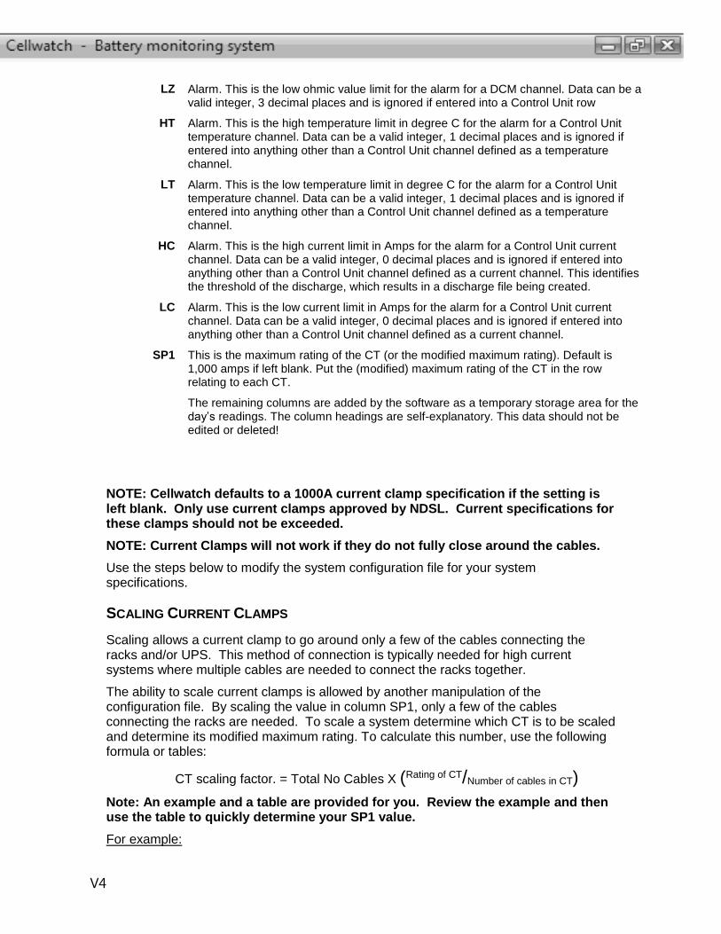
V4
LZ Alarm. This is the low ohmic value limit for the alarm for a DCM channel. Data can be a valid integer, 3 decimal places and is ignored if entered into a Control Unit row
HT Alarm. This is the high temperature limit in degree C for the alarm for a Control Unit temperature channel. Data can be a valid integer, 1 decimal places and is ignored if entered into anything other than a Control Unit channel defined as a temperature channel.
LT Alarm. This is the low temperature limit in degree C for the alarm for a Control Unit temperature channel. Data can be a valid integer, 1 decimal places and is ignored if entered into anything other than a Control Unit channel defined as a temperature channel.
HC Alarm. This is the high current limit in Amps for the alarm for a Control Unit current channel. Data can be a valid integer, 0 decimal places and is ignored if entered into anything other than a Control Unit channel defined as a current channel. This identifies the threshold of the discharge, which results in a discharge file being created.
LC Alarm. This is the low current limit in Amps for the alarm for a Control Unit current channel. Data can be a valid integer, 0 decimal places and is ignored if entered into anything other than a Control Unit channel defined as a current channel.
SP1 This is the maximum rating of the CT (or the modified maximum rating). Default is 1,000 amps if left blank. Put the (modified) maximum rating of the CT in the row relating to each CT.
The remaining columns are added by the software as a temporary storage area for the day’s readings. The column headings are self-explanatory. This data should not be edited or deleted!
NOTE: Cellwatch defaults to a 1000A current clamp specification if the setting is left blank. Only use current clamps approved by NDSL. Current specifications for these clamps should not be exceeded.
NOTE: Current Clamps will not work if they do not fully close around the cables.
Use the steps below to modify the system configuration file for your system specifications.
SCALING CURRENT CLAMPS
Scaling allows a current clamp to go around only a few of the cables connecting the racks and/or UPS. This method of connection is typically needed for high current systems where multiple cables are needed to connect the racks together.
The ability to scale current clamps is allowed by another manipulation of the configuration file. By scaling the value in column SP1, only a few of the cables connecting the racks are needed. To scale a system determine which CT is to be scaled and determine its modified maximum rating. To calculate this number, use the following formula or tables:
CT scaling factor. = Total No Cables X (Rating of CT/Number of cables in CT)
Note: An example and a table are provided for you. Review the example and then use the table to quickly determine your SP1 value.
For example:

192 V 5.2.9 - November 2015
System A has 5 cables connecting the string rack to the UPS. A current clamp, rated at 1000A, is placed around only 3 cables due to the large size of the cables. Presently the system reads 3/5 of the actual current because the clamp is around only 3 of the 5 cables. Using the table provided below, locate the line that says there are 3 out of 5 cables being measured in the cable column. The 1000A value for 3 out of 5 is 1667. This value is the CT modified maximum rating value and will be entered into the SP1 column.

V4
Note: Use the following table to determine what SP1 value you will use.
Cables 1000A Clamp 2500A Clamp
# Measured out of Total SP1 Value
1 out of 2 2000 5000
1 out of 3 3000 7500
1 out of 4 4000 10000
1 out of 5 5000 12500
1 out of 6 6000 15000
2 out of 3 1500 3750
2 out of 4 2000 5000
2 out of 5 2500 6250
2 out of 6 3000 7500
3 out of 4 1333 3333
3 out of 5 1667 4167
3 out of 6 2000 5000
4 out of 5 1250 3125
4 out of 6 1500 3750
5 out of 6 1200 3000
NOTE: The diagnostic program always reads the un-scaled current.
Changes will not take effect unless Cellwatch is Stopped, Closed and restarted.
Single String Current
To change the current clamp specifications for a string follow these steps. These steps can be modified to adjust the current clamp specifications for a whole system or a system battery by modifying the steps. This will allow various approved current clamps to be mixed within a system.
1. Stop Cellwatch Operation by Selecting the ‘Start/Stop’ drop down menu and right clicking on ‘System Stop’
2. Select the ‘Configuration’ drop down menu and select ‘View Configuration’
3. Select the ‘Edit’ drop down menu and LC on ‘Edit Config data’
4. Enter the user password deafcat for the Cellwatch monitoring program
5. Select ‘OK’ on the Information prompt (Note: This prompt signals that the configuration file has been backed up)
6. Select any box within the white field.

194 V 5.2.9 - November 2015
7. Scroll down with the down arrow key until you reach the first cell of the Control Unit (CU) that you would like to change. CU’s can be located by looking for a ‘C’ within the TY column. The address of the CU is shown in the CU column.
CU’s are labeled as DCM = 0, and TY = C. See the circled area above for clarification.
8. Locate the channel address for the current clamp that you are configuring, this can be found in the CT column. Note CT1.will be plugged into socket 1 on the CU, 2 into 2 etc.
9. Press the Right Arrow Key and move the box to the right until you reach the column labeled ‘SP1’
NOTE: When changing an entire system, it is easiest to select the entire column. To do so, simply go to the top of the SP1 column, and hold the shift key and then depress the down arrow key until all keys are selected.
10. Type the maximum rating of your current clamp (or modified max rating)
Max Current Clamp Rating Enter This Value
1000 Amps 1000
2500 Amps 2500
X Amps X
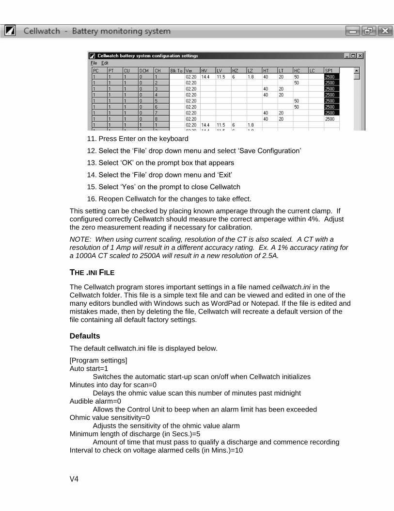
V4
11. Press Enter on the keyboard
12. Select the ‘File’ drop down menu and select ‘Save Configuration’
13. Select ‘OK’ on the prompt box that appears
14. Select the ‘File’ drop down menu and ‘Exit’
15. Select ‘Yes’ on the prompt to close Cellwatch
16. Reopen Cellwatch for the changes to take effect.
This setting can be checked by placing known amperage through the current clamp. If configured correctly Cellwatch should measure the correct amperage within 4%. Adjust the zero measurement reading if necessary for calibration.
NOTE: When using current scaling, resolution of the CT is also scaled. A CT with a resolution of 1 Amp will result in a different accuracy rating. Ex. A 1% accuracy rating for a 1000A CT scaled to 2500A will result in a new resolution of 2.5A.
THE .INI FILE
The Cellwatch program stores important settings in a file named cellwatch.ini in the Cellwatch folder. This file is a simple text file and can be viewed and edited in one of the many editors bundled with Windows such as WordPad or Notepad. If the file is edited and mistakes made, then by deleting the file, Cellwatch will recreate a default version of the file containing all default factory settings.
Defaults
The default cellwatch.ini file is displayed below.
[Program settings] Auto start=1 Switches the automatic start-up scan on/off when Cellwatch initializes Minutes into day for scan=0 Delays the ohmic value scan this number of minutes past midnight Audible alarm=0 Allows the Control Unit to beep when an alarm limit has been exceeded Ohmic value sensitivity=0 Adjusts the sensitivity of the ohmic value alarm Minimum length of discharge (in Secs.)=5 Amount of time that must pass to qualify a discharge and commence recording Interval to check on voltage alarmed cells (in Mins.)=10

196 V 5.2.9 - November 2015
Interval to monitor voltage on voltage alarmed cells after discharge Time limit to check on voltage alarmed cells (in Mins.)=60 Maximum time limit to monitor voltage on voltage alarmed cells after discharge Number of temperatures to average=10 Number of temperature readings to average Degrees for temperature alarm Hysteresis (x0.1, e.g. Enter 7 for 0.7 degrees) =7 Setting used in resetting the temperature alarm. Display Temperature in C=1 Adjusts the display for temperature between Celsius and Fahrenheit (see below) Language=1 Adjusts the language that Cellwatch is translated in (see below) Voltage sensitivity=5 Number of ‘in-alarm’ scans it takes to activate an alarm during Constant V. Scan [Modbus] Enabled=1 System Unit ID=1 [HTTP] Enabled=1 Authorization needed=0 Enables the webpage to be protected by the default password System page refresh period=10 Interval for system webpage updates Battery page refresh period=10 Interval for battery webpage updates String page refresh period=60 Interval for string webpage updates Info page refresh period=10 Interval for info page to update Maximum log file count=0 Limits the number of Cellwatch log files that can be listed Maximum discharge file count=50 Limits the number of discharge files that can be listed [Scan frequency settings] Voltage=1 Interval of hours to pass for voltage scans Ohmic value=24 Interval of hours to pass for ohmic value scans [AppServer] This block set contains system settings for Cellwatch to communicate alarm events to the AppServer database. [Autoset] This block set contains configuration information for Cellwatch to run the Autoset settings. Note that modifying contents in this setting can prevent Autoset from running any scheduled adjustments or any future adjustments yet to be scheduled.

V4
[Thermal] Interval=12 This is the delay interval for Thermal Runaway alarms. Modifying this between 1
and 12 (hours) will adjust the delay period for removing a string from operation or user delay events.
There are several sectors of settings located under Program Settings, Modbus, HTTP and Scan Frequency Settings. In general the number ‘0’ means ‘OFF and ‘1’ means ON. Hence many of the lines of the file become self-explanatory. The changes to the ini file only take place after the Cellwatch application has been restarted.
Some useful features of the file are as follows:-
[Program Settings];
Minutes into day for scan. This setting allows Cellwatch to change the way it records ohmic value scans. The setting shifts the first ohmic scan for the day, allowing for ohmic value scans to be completed at a specified time, for example 8:15 a.m.
Note that the delay value is in minutes.
Use the following example to set the ohmic scan at 8:15am:
8 Hours * 60 + 15 Minutes = 495 Minutes
Minimum length of discharge (in Secs.)=5 this sets a time criteria for Cellwatch to recognize both the temperature current alarm condition as a genuine alarm and start to record a discharge file or temperature alarm event.
Normally current flows take place all the time within UPS batteries, many of these can be recognized by Cellwatch as a discharge if the current alarm criteria is set low. A time criteria has been added such that if the current alarm is tripped for at least this time period (in seconds) it is regarded as a proper discharge and the data (which includes readings taken during the qualifying few seconds) is recorded into a discharge file (for further information on discharge files, see earlier in the Software Guide).
Interval to check on voltage alarmed cells (in Mins.)=10 following a discharge it is likely that cell voltages will be reduced considerably. Hence when the UPS returns to a charging state, voltage alarms will still be set until such time as voltage levels are back above Voltage Low Alarm thresholds AND a voltage scan takes place. To avoid alarms remaining in a set condition for a long time after a discharge Cellwatch now repeats the voltage scan at an interval defined in this statement. This setting is overridden by constant voltage scanning.
Time limit to check on voltage alarmed cells (in Mins.)=60 The number of minutes that Cellwatch performs voltage scans to clear voltage alarms that occurred during a discharge. This setting is overridden by constant voltage scanning.
Degrees for temperature alarm Hysteresis (x0.1 e.g. Enter 7 for 0.7 degrees)=7 Hysteresis has been built into Cellwatch when resetting a tripped temperature alarm. The value defined in this line of the .ini file is either added to (in the case of the lower) or subtracted from (the higher) alarm limit and is used to reset a tripped alarm. This is only applied if there is double the value (default 0.7 deg C, hence 1,4 deg C) between the upper and lower limit. If the value difference between the upper and lower alarm limit is

198 V 5.2.9 - November 2015
not greater than double the hysteresis limit set in this file, then 10% of the upper and lower difference is used for hysteresis.
Display temperature in C=1 (or0) If Celsius (or Centigrade) is required, use C=1 if Fahrenheit is required use C=0.
Language = 1 Cellwatch natively operates in a number of languages as defined below:
Language Language = ##
English 1
French 2
Chinese 3
Korean 4
Japanese 5
[HTTP]
HTTP Authorization needed: If this is set to a 1, then a user ID and password are required for web page viewing on a remote browser. The ID is Cellwatch and the password is deafcat.

V4
SOFTWARE: TROUBLESHOOTING & MAINTENANCE
Fiber retesting
If the fiber optic network loop is broken, due perhaps to maintenance of the cells, mono-blocs or jars, then the system will mark the afflicted string or battery by turning the relevant blocks gray in color.
Breaks in the fiber optic link cannot be repaired by the system. To cope with the eventuality that this may have been a spurious problem OR should the problem be cured by an engineer, the system will automatically re-try the optical loop with the problem (if not monitoring a discharge) by trying to read a voltage from the first cell. Should the loop check out OK on a subsequent re-try then the blocks will be re-enabled as green (if no alarm limits exceeded) or red (if alarm limit exceeded).
An appropriate entry to the log-file is made.
Password persistence
If a correct password is entered into Cellwatch to allow access to any of the password protected areas, such as configuration editing or diagnostic testing, then repeated re-entry to that and all other password protected areas is not required until a 10 minute time-out expires. This password time out is initiated when the LAST successful entry into a restricted area took place.
Exiting the Program
In order to exit the Cellwatch program the user should first stop any scanning that is taking place using the Start/Stop - System Active drop down menu. Any attempt made to
exit the program while running using the button Alt-F4 or the exit function described in Chapter 1 is blocked and a warning box presented to the user warning that the program should be stopped first.
However, if the battery monitoring system has been damaged or interfered with it may be necessary to exit the program without first stopping it. This can be achieved from the system menu invoked by clicking on the icon in the top left hand corner of the window. The last menu item is Shutdown Cellwatch. Clicking this function invokes a warning box asking the user to close down Cellwatch normally. If the user responds by pressing the No button Cellwatch closes regardless of program condition.


201
USER MANUAL

202 V 5.2.9 - November 2015
USER MANUAL: INTRODUCTION
Thank you for choosing and trusting Cellwatch Battery Monitoring Systems to help ensure your standby power battery is in the best condition it can be when you will need it.
This short guide is aimed at the technical user who wants to make sure he or she gets the best out of Cellwatch and hence the best out of the batteries it monitors.
Cellwatch is a precision system which should give years of valuable service and dependable information about your battery. With Cellwatch you should be able to determine your battery health and isolate failed or failing cells before they become a problem for you. Cellwatch is a comparative tool which does require some knowledge to get the best from it. This manual is intended to help guide you through and to get the best from your Cellwatch battery monitoring system. Time spent reading this manual should prove very valuable.
IMPORTANT NOTE ON POWER FAILURES AND TURNING OFF AN IBMU
Cellwatch should not be turned off unless scheduled maintenance is occurring. The following points should be followed at all times to ensure that Cellwatch is capable of monitoring your batteries during unforeseen events such as power loss to the iBMU or any CUs.
The iBMU and CU or TRC modules should always be powered from a UPS backed outlet. In the event of a utility failure Cellwatch will monitor your battery performance during the discharge event. If the iBMU is powered off, or if the CU or TRC modules are powered off, Cellwatch cannot capture information on the discharging battery.
Every iBMU has been configured to automatically power on and log into the Cellwatch account when power is applied. This ensures that following a power failure, Cellwatch will immediately attempt to begin scanning the batteries.
iBMUs should not be placed on a domain. Placing an iBMU on a domain requires the iBMU to have server authentication (i.e. permission) to log in. Ensure that your IT department allows permissions for the server to continue to boot into the Cellwatch account so your batteries are monitored. The Cellwatch software must be actively running to monitor and collect information from the batteries.
Powering off any operating system without using the shutdown feature and allowing the system to power off runs the risk of corrupting data on the hard disk. When powering off a system always attempt to use the Shutdown command in the Start menu.

203
USER MANUAL: VALIDATE THE SYSTEM
How do you, the user of Cellwatch, know that the system is working correctly? This section will give you enough information to verify that the system is working as we intended it to.
IS IT WORKING?
The Cellwatch system’s most basic way of communicating with you, the user, is through a computer screen. This screen can be connected directly to the unit or can be viewed through your desktop computer or you could be looking at the Cellwatch system over a network using Remote Desktop.
When you look at the screen there are certain key things to look for to identify that it is working correctly.
Indications that Cellwatch is not running…
The first indication that Cellwatch is not running is derived from the Alerts window. A link will appear next to the notification that Cellwatch is stopped allowing the user to get the system scanning again.
The second indication that the Cellwatch software is not actively scanning is identified by the searchlight logo in the upper right hand corner of the screen. If this logo is not actively sweeping or missing, Cellwatch is not scanning your batteries.
The third indicator that the Cellwatch software is not scanning can be found in the webpage interface. The webpage will indicate in RED letters that the Cellwatch software is stopped. If the webpage does not appear it is because either Cellwatch is not running or the user has disabled the webpage interface.
Each of these can be resolved by using the Start/Stop > System Active in the drop down menu, by using the quick fix link in the Alerts box, or by closing and re-opening Cellwatch.
Logo indicates Cellwatch is running
Status indicates if
Cellwatch is scanning
Green and Red indicators indicate alarm status
Status box indicates last scan time

204 V 5.2.9 - November 2015
On the webpage interface you will see updated battery information. If you see RED letters on the screen saying that Cellwatch is stopped, the software is running, but not actively monitoring your batteries. If the webpage is not accessible then either the webpage interface has been turned off by a user or the software is not running.
IS IT INSTALLED & CONFIGURED CORRECTLY?
Take a look at the screen and look carefully at the battery and string tabs. The number of discrete battery tabs that you have should describe the number of UPS modules or battery-banks being monitored. Each battery-bank should contain the correct number of strings that make them up. If strings have been mistaken for batteries (or vice-versa) the system may not function exactly as designed.
Each string panel should contain the correct number of cells or jars or blocs. This might be 40 x 12 volts blocs for a 480 volt battery or more for a wet cells system.
The image above represents 5 UPS modules or 5 battery banks each containing 1 string (although you cannot be sure, because the non-selected batteries are hidden). If any battery goes into discharge, only the battery(s) in discharge will be scanned and recorded.
The image above represents a single UPS module or battery bank with 5 separate strings. Any single string goes into discharge and the entire battery’s individual cell voltages will be continuously scanned and recorded
This image is how it would look if you had multiple batteries each with multiple strings.
ARE THE ALARMS SET UP CORRECTLY?
The alarm limits for the four parameters (voltage, ohmic value, current and temperature) are your best guide to the health of the battery on a regular basis. When the system is installed, widely spaced settings are created that allow the installer to debug the system.
The last action of configuring any system is setting alarms. Alarm limits should be set up according to your battery and its age and condition.
See the chapter; Software: Operation and Set-up of Alarm Functions.

205
Alarms may be set for individual cells or strings which may not be visible in the global alarms settings. You can still view the custom alarms by selecting the graph limits button beneath each alarm setting in any alarms window.
ARE THE CELLS GREEN OR RED (I.E. IN ALARM)?
Cellwatch works 24 hours a day, even though you do not. It is also constantly scanning your batteries for discharge events, temperature issues, and voltage alarms (when in constant voltage scan mode). Alarmed cells may appear either Red or Green. Yellow indicates that Cellwatch is collecting information from the monitored channel.
Cellwatch tells you about problems in a number of ways:
On screen using red colored tabs and cells.
Utilizing dry contacts within the CU or TRC.
Via the network on a Web-browser using red alarm squares.
Over the Email system using EmailAlert or Cellwatch.net (a subscription service).
On your building management system via the MODBUS/TCP or other interface.
To determine what is triggering the alarmed event, simply follow the Red indicators. Battery tabs will highlight Red if any monitored cell, string, or probe associated with that battery is in alarm. String tabs will highlight Red if any monitored cell or probe associated with that string is in alarm. Individual cells may highlight red if an alarmed condition is detected on the cell level.
It is highly recommend to have a permanent monitor setup connected to your iBMU. A KVM switch is recommended if more than one IBMU are utilized due to the size of the installation. Alternately, some users establish a remote connection into the system allowing battery status information to be visible outside of the battery room or remotely from the site itself.
Note the hover indicator and the red battery, string, and cell indicators

206 V 5.2.9 - November 2015
If there is nothing connected to the Cellwatch system, then it cannot tell you of a problem.
Make sure that someone in your organization is able to review the system and knows what to do if something looks wrong.
End user training classes are available by NDSL aimed at helping the end user take control of their battery asset.

207
USER MANUAL: WHAT TO LOOK FOR
THE DAILY OR WEEKLY CHECK
There are three primary consider when checking your Cellwatch system:
1. Is Cellwatch running? (see above)
2. Are there any Red events in Cellwatch or Data Manager?
3. When was the last time I reviewed my history file?
Look at the Cellwatch screen and make sure it is active. Look for the Cellwatch logo in the top right hand corner and make sure all of the cells on the screen are green or flashing yellow.
If any cells remain yellow for a long time, you have a problem and need to call your installation company for assistance.
Cells that are red should be investigated.
Alarm Conditions – Red Tabs, Cells, or Data Manager Events
If either cell voltage, string voltage, cell ohmic value, temperature, thermal runaway condition, or string current goes out of set limits, then the software will indicate an alarm by turning the (normally green) square in the battery tab and corresponding string tab to RED.
If the alarm is due to Voltage or Ohmic Value going outside either the upper or lower limits, then the associated cell panel(s) will also turn RED:
If there is a red battery tab and/or cell in the panel – this should be investigated. NOTE to bring the string containing the red cell to the surface, then click the alarmed battery, then the subsequent alarmed string. If you need to know why the cell has alarmed, right click the alarmed cell and select Alarm Reason from the drop down menu.
Hover over the battery tab to identify the cause of the alarm: Voltage Ohmic-value, Thermal Runaway, Current or Temperature.
Data Manager will indicate active alarm events by highlighting the event red. Once the event has ended, an end time will appear however the event will remain unacknowledged so that users can quickly identify new events that occurred between checks.
Volts or Ohms
If the alarm is caused by a voltage or an ohmic-value out of limits then the actual data can be reviewed by hovering over the red cell.
Here are the causes of the three most common alarms:-
High ohmic-value: This is the most valuable indicator that a jar is going to fail. NDSL recommends setting the upper ohmic-value alarm level at 20% to 25% of the steady state, on charge value of the jar. When the jar exceeds this alarm limit, the history file should be reviewed for this jar and a replacement considered.
When you have determined what condition is causing the red alarm, you should always review the history for the suspect jar. We recommend you do this by right clicking on the red cell depiction and selecting “Cell history”. This will display the voltage and ohmic-
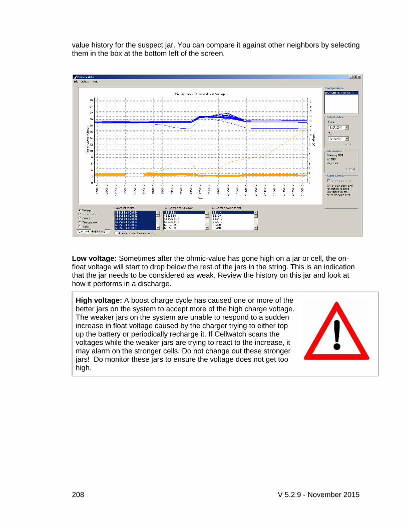
208 V 5.2.9 - November 2015
value history for the suspect jar. You can compare it against other neighbors by selecting them in the box at the bottom left of the screen.
Low voltage: Sometimes after the ohmic-value has gone high on a jar or cell, the on-float voltage will start to drop below the rest of the jars in the string. This is an indication that the jar needs to be considered as weak. Review the history on this jar and look at how it performs in a discharge.
High voltage: A boost charge cycle has caused one or more of the better jars on the system to accept more of the high charge voltage. The weaker jars on the system are unable to respond to a sudden increase in float voltage caused by the charger trying to either top up the battery or periodically recharge it. If Cellwatch scans the voltages while the weaker jars are trying to react to the increase, it may alarm on the stronger cells. Do not change out these stronger jars! Do monitor these jars to ensure the voltage does not get too high.

209
POST DISCHARGE EVENT CHECK
Anytime the battery goes onto load (discharge) for more than 5 seconds, Cellwatch will generate a discharge file for the discharging battery. This will produce an automatic load-test curve for every jar on the battery under load. Along with the ohmic-value history, this is the most useful data set as it will either identify or confirm weak cells on the system.
Following a discharge event, open a discharge graph and review the voltage curves. The first graph open shows the best performing and worst performing jars on the system. The jar seen failing above (jar 49) can clearly been seen as failing during a discharge.
Correlation between an alarm limit being exceeded, a history graph showing gradual deterioration and a discharge graph showing performance failure requires no further testing. The jar should be changed.
When looking at a discharge graph also review the current (and temperature) data. In particular the discharge currents from parallel strings should typically be equal – and they should all be negative.
An imbalance (ex. Two of three strings provide 60 amps while the third string only supports 25 amps) between the strings indicates a high resistance path
210 V 5.2.9 - November 2015
in a string, possibly a jar or bad cable connection. On the other hand a positive current curve shown amongst other negative current curves indicates that a Current Transducer (CT) has been fitted the wrong way around. Contact your service organization to fix this problem.
PERIODIC REVIEW
It is good practice to review the history data for all the cells on a battery from time to time to ensure that the information is being collected correctly and that nothing untoward has happened to the system. Only by actively reviewing and engaging your Cellwatch data on a regular basis can users stay ahead of potential battery failures.

211
USER MANUAL: OTHER FUNCTIONS AND TASKS
OTHER USEFUL TOOLS
A number of other tools have been made available to help users manage their battery asset. Below is a short list of available tools recommended for end users.
File Viewer
File Viewer is a downloadable client that can be installed end customer computers running the Windows operating system. This tool allows users to open history and discharge files without using the Cellwatch interface. For example, a user can navigate to the webpage interface hosted by Cellwatch or to the backup database in Cellwatch.net and download their latest history or discharge files to their computer for viewing.
Email Notifications
Two email notification systems are available through Cellwatch.
Email Alert
Email Alert is free for all Cellwatch 4.0 and later users; they simply have to register the client. This tool allows users to send email notifications via their own internal SMTP servers. Always use the latest installer when installing this product to ensure you can receive all available alarm notifications.
Cellwatch.net (a subscription service)
Cellwatch.net also provides standard email notifications but also allows users:
Exclusive use of the Cellwatch.net SMTP server (optional)
To daily back up their Cellwatch data to a secure server
Access to the latest history, discharge, and alarm information from their battery from anywhere through the secure website
Take advantage of a heartbeat notification which alerts you when email notifications have stopped which could indicate that Cellwatch has been disabled for some reason
SNMP Agent
Cellwatch also has a SNMP agent available for users that wish to integrate Cellwatch into an existing building management system that uses SNMP. Additional information can be obtained by contacting your Cellwatch provider.
EXPORTING THE DATA TO MICROSOFT® EXCEL OR CSV
It is possible to use “raw data” generated in the Cellwatch program in other applications such Microsoft EXCEL. The following export opportunities exist:-
1. Capture all the readings taken by Cellwatch TODAY, and view it in Excel.
2. Export the raw data from the History file.
3. Export the raw data from a Discharge file.
Older versions of the Excel software limit the number of available columns to 256. This is not enough columns to view Cellwatch data. Versions later than 2007 do not have this

212 V 5.2.9 - November 2015
limitation. For instructions on older versions of Excel, please consult an older manual or contact Technical Support.
CAPTURE THE PRESENT DAY’S READING TAKEN AND STORE IT IN EXCEL.
1. If you intend to carry out this procedure at (say) 6.00 a.m. then you will only capture the data recorded from midnight through to 6.00 a.m. More data will be captured at 11.00 p.m. than at 6.00 a.m.
2. On the Cellwatch screen select the drop down menu “Configuration” and select “View Configuration” from the drop down menu.
3. The screen that opens, looks like a spreadsheet and is entitled
4. On its drop down menu, select “File” and select “Save data as” from the drop down list.
5. Save the data as a .CSV file to the Cellwatch folder.
6. Copy the data to a memory stick or floppy disk or a network share. Do not try to run Excel on the Cellwatch iBMU.
7. Having transferred the data to a PC running Microsoft Excel, open Excel and import the data into Excel (additional instructions are below if assistance with Excel are needed).
CONVERT THE HISTORY FILE INTO A CSV FOR EXCEL OR OTHER PROGRAMS
1. Create a copy the history file you wish to view. This can be done by right clicking the file and selecting copy, then right clicking in the white space and selecting paste. A new file will appear called “copy of historyYYYY.his” where YYYY is the year of the file you copied.
2. Rename the file to change the extension to a .csv by right clicking the file and selecting rename. NOTE: Some systems may be configured to not show file extensions. This can be adjusted by modifying Folder settings within Windows.
3. Open Microsoft Excel.
4. Left click on the menu entitled “Data”.
5. This will cause a dropdown window to appear. Select “Import From Text” with the mouse cursor. This will cause a file selection window to appear. Navigate to and select the “historyYYYY.csv” file.
6. A text import wizard will appear. When asked if the file is delimited, select ‘delimited’.
7. When asked for the type of delimiter, ensure that only ‘comma’ is checked.
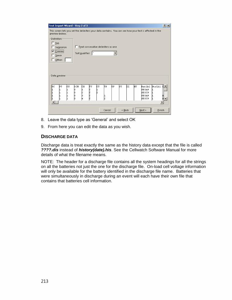
213
8. Leave the data type as ‘General’ and select OK
9. From here you can edit the data as you wish.
DISCHARGE DATA
Discharge data is treat exactly the same as the history data except that the file is called ????.dis instead of history(date).his. See the Cellwatch Software Manual for more details of what the filename means.
NOTE: The header for a discharge file contains all the system headings for all the strings on all the batteries not just the one for the discharge file. On-load cell voltage information will only be available for the battery identified in the discharge file name. Batteries that were simultaneously in discharge during an event will each have their own file that contains that batteries cell information.
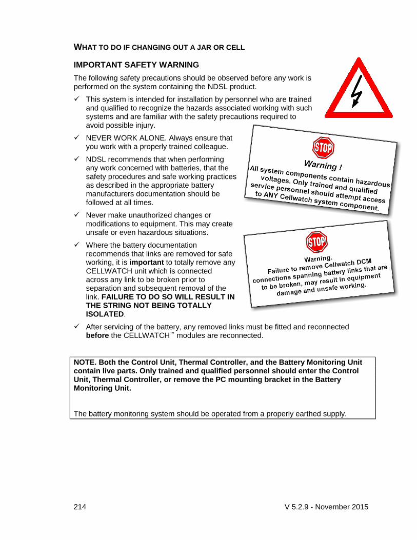
214 V 5.2.9 - November 2015
WHAT TO DO IF CHANGING OUT A JAR OR CELL
IMPORTANT SAFETY WARNING
The following safety precautions should be observed before any work is performed on the system containing the NDSL product.
This system is intended for installation by personnel who are trained and qualified to recognize the hazards associated working with such systems and are familiar with the safety precautions required to avoid possible injury.
NEVER WORK ALONE. Always ensure that you work with a properly trained colleague.
NDSL recommends that when performing any work concerned with batteries, that the safety procedures and safe working practices as described in the appropriate battery manufacturers documentation should be followed at all times.
Never make unauthorized changes or modifications to equipment. This may create unsafe or even hazardous situations.
Where the battery documentation recommends that links are removed for safe working, it is important to totally remove any CELLWATCH unit which is connected across any link to be broken prior to separation and subsequent removal of the link. FAILURE TO DO SO WILL RESULT IN THE STRING NOT BEING TOTALLY ISOLATED.
After servicing of the battery, any removed links must be fitted and reconnected before the CELLWATCH™ modules are reconnected.
NOTE. Both the Control Unit, Thermal Controller, and the Battery Monitoring Unit contain live parts. Only trained and qualified personnel should enter the Control Unit, Thermal Controller, or remove the PC mounting bracket in the Battery Monitoring Unit.
The battery monitoring system should be operated from a properly earthed supply.

215
REMOVAL AND REFITTING OF A DCM
Adhering to all battery manufacturers and site safety rules perform the following in the following order:
1. Use the Cellwatch software to identify the Cell(s) to be changed.
2. Using the Start/Stop menu on the Cellwatch software to Stop the program.
3. Right click the jar to be changed and select “Ping continuously” to flash a light on the DCM adjacent to the jar to be changed. This will ensure you change the correct jar and easily identify the DCM.
4. Electrically isolate the battery.
5. Identify all connections from the Cellwatch DCM that spans the cell(s) to be replaced. There are seven cables all together. It is recommended that as the cables are removed, they are labeled so that they can be reconnected to the same point later.
6. If it is necessary to remove the fiber optic cable, in order to move the Cellwatch module out of the way, label each free end of the fiber so that it is clear on reconnecting which fiber goes into the black or white connector.
7. Remove the green, yellow and orange wires from the battery leading to the DCM identified above.
8. Remove the red and brown wires from the battery.
9. Remove the blue and white wires from the battery.
10. Disconnect the battery links
11. Replace the faulty cell / jar.
12. Reconnect the battery links.
13. Connect ALL of the DCM leads to the correct locations in reverse order of removal.
14. Close the breaker as appropriate.
15. Restart the CELLWATCH software and ensure that it identifies all the modules. If it doesn’t then ensure that the fiber optic path is continuous.
16. Allow the program to complete one pass of voltage readings, checking that the values are correct. If several of the voltage readings appear strange, e.g. one channel reads 24 V and another channel reads 0 V, then recheck the order of the red leads and adjust accordingly.

216 V 5.2.9 - November 2015
ADDING MORE HARDWARE (STRINGS OR BATTERIES)
Cellwatch maintains a record of all averaged daily results for a year in a file named historyzzzz.his where zzzz is the year. So History2006.his is the file for 2006’s history.
This file can first be read on the third day after installation and no effort is necessary on the part of the installer or user to create this file as the Cellwatch software creates it automatically.
However, because of how this file is created some care and consideration needs to be given to the workings of the software when installing or changing configurations.
WHEN YOU FIRST START CELLWATCH
The history file is created automatically just after midnight on the day after install. The daily data is stored in columns and rows in the file, just like in a spreadsheet. So that the program knows what data each column or row contains it creates headers that are text labels to identify the data. The header for the file is the configuration file ‘batconfig.cfg’. Organized very much like a spreadsheet, the file stores data against each entry taken from the configuration file.
Problems have occurred where a system is installed and left running and shortly afterwards the system configuration is changed as more UPS module batteries are installed and added to the configuration. If this happens, the original file integrity is maintained but only data for the initial file is added to the history file. This is because the initial headers for the history file is the batconfig.cfg file that was in use the night the system is first left running. Cellwatch cannot add extra headers to the file once created.
Simply renaming the history file to something similar to “historyYYYY_part1.his” will ensure that you are saving the new configuration.
HOW TO DO IT RIGHT.
If you do a phased start-up, delete the historyzzzz.his file or rename it each time you change the batconfig.cfg file. If you rename the file you can still view it through the history file view facility in Cellwatch as long as you leave the file extension as ‘.his’.
If, after the system has been commissioned the user requests more UPS batteries be added to the system, the same rule still applies. Rename the historyzzzz.his file where zzzz is the CURRENT year (to say historyzzzzpart1.his) and let Cellwatch create its new history file for the new configuration which can be viewed three days afterwards.

217