Embed Size (px)
Citation preview

CHAPTER 14
Cellulose and Protein Aerogelsfor Oil Spill Cleaning, LifeScience and Food EngineeringApplications
HAI M. DUONG,* PENG LIU, THANH X. NGUYEN,SON T. NGUYEN, JINGDUO FENG AND HANLIN CHENG
Department of Mechanical Engineering, National University of Singapore,9 Engineering Drive 1, EA-07-05, Singapore 117575, Singapore*Email: [email protected]
14.1 IntroductionOil spills are considered to be one of the most serious disasters threateningthe marine ecosystem. Recently, the explosion of a drilling rig in the Gulf ofMexico caused significant environmental damage.1 Oil spills are usuallyrelated to accidents during oil production, storage, and transportation. Aslong as fossil fuels are needed, oil spills will remain a significant problemthat human beings will have to face.2–8 Therefore, it is essential to solve, or atleast alleviate, this environmental problem.
Several methods of oil spill–cleaning have been developed, and can beclassified as chemical, biological, and physical methods. Dispersion, in situburning, and solidification are considered to be chemical methods that arecomplicated and expensive.9–11 The use of microorganisms via biological
Green Chemistry Series No. 58Biobased Aerogels: Polysaccharide and Protein-based MaterialsEdited by Sabu Thomas, Laly A. Pothan and Rubie Mavelil-Samr The Royal Society of Chemistry 2018Published by the Royal Society of Chemistry, www.rsc.org
228
1
5
10
15
20
25
30
35
40
45

methods is effective but requires a long time,
TS:1
and the microorganisms areaffected by environmental factors, such as pH, temperature, and oxygencontent.12 Moreover, oil spills cleaned using chemical and biologicalmethods are difficult to recover, and recoverability is a crucial factor for oilspill–cleaning applications. With regards to the physical methods, boomsand skimmers are often used, but cannot remove oil from the sea effect-ively.13 Of these methods, sorption has been considered one of the mosteffective ways for oil-spill cleaning, as it enables the collection and completeremoval of oil from oil-spill sites.2,11,14–20
Several materials have been used as sorbents for oil-spill cleaning in bothresearch and practical applications. The oil absorbents can be categorizedinto inorganic minerals, natural organic materials, and synthetic organicmaterials.11,16,17,19 Inorganic materials, such as clay, vermiculite, exfoliatedgraphite, diatomite, and fly ash, have low oil absorption capacities(4–20 g g!1).21–23 Furthermore, some of these inorganic materials, such asclay and vermiculite, are harmful when inhaled by human beings underwindy conditions, due to the loose structures of these materials. Naturalorganic materials from plant and animal residues, such as kapok fibre,sugar-cane bagasse, rice husk, coconut husk, cotton, wool, sawdust, andchitosan, have been examined for oil absorption capabilities.24–26 However,most of the materials have low oil absorption abilities (3–15 g g!1), and alsoabsorb water.
On the other hand, synthetic organic materials, such as polypropylene,polystyrene, and polyurethane, possess a high affinity with oil and high oilabsorption capacities (4.5–100 g g!1), but cause waste problems after use dueto their slow rates of degradation.11,16,19 Therefore, there is high demand fornew environmentally friendly absorbents with a high oil absorption capacity,good selectiveness, and low cost for oil-spill removal.
A combination of an aerogel structure and recycled cellulose fibres frompaper waste can be used to form an advanced material, called a recycledcellulose aerogel, which is cost-effective and a promising material for oilabsorption. Although some studies have investigated the use of cellulosicmaterials for oil absorption, none have fabricated aerogels from paper-wastecellulose fibres and investigated them as absorbents for crude oil-spillcleaning.2,5,27–31
The increase in paper consumption has created huge amounts of paperwaste, which accounts for 25–40% of global municipal solid waste.32 In 2004alone, 360 million tonnes of paper-related waste was generated worldwide.Moreover, paper and paperboard consumption will increase the amount ofwaste produced by 2.1% each year until 2020, which suggests that more than500 million tonnes of paper waste can be expected in 2020.33 In addition,incineration or landfill of the paper waste could damage the environmentfurther with toxic emissions and groundwater contamination.
Recycling paper waste will help to preserve forests and solve the en-vironmental problem. Therefore, it is important to recycle or convert thisenormous amount of waste into useful products. Several efforts have been
1
5
10
15
20
25
30
35
40
45
Life Science and Food Engineering Applications 229

made to solve this problem. For instance, in 2010, 63% of paper waste wasrecycled in the US.34 Paper waste has also been investigated as a raw materialfor production of bioethanol, polymer precursors, particleboard, and soforth.32,35,36 Commercially, recycled paper is mainly converted into otherpaper commodities of lower quality grades than the original products.37 Inaddition, the maximum conversion rate from paper waste to other paperproducts is only approximately 65%.37 This low conversion rate is due to thelength degradation of the cellulose fibres during the recycling processes,which also compromises the quality of the end product.37 In addition,waste fibres of short lengths generated during recycling are discarded,as they are not suitable for further recycling.37 It is therefore necessary todevelop alternative commodities from paper waste. Although some studieshave examined the use of cellulosic materials for oil absorption, none havecovered the fabrication of aerogels from paper-waste cellulose fibres, andinvestigated the aerogels as absorbents for the cleaning of crude-oilspills.2,5,27–31
Recycled cellulose fibres from paper waste are a cheap and abundantresource; the price of scrap paper was approximately $100/ton in 2015.38
A combination of the aerogel structure and recycled cellulose fibre constitutea new material – called a recycled cellulose aerogel – which is cost-effectiveand has the potential for oil absorption.39–41 The recycled cellulose aerogeland its silica composite aerogel can also potentially be used as thermal-insulation materials for buildings.41 Therefore, all the practical applicationsdeveloped may contribute to the recycling of paper-related waste. This bookchapter presents the basic facts about cellulose materials, and comprehen-sive information about cellulose aerogels and silica–cellulose compositeaerogels. Both the fabrication methods and properties of cellulose aerogelsand silica–cellulose aerogels are discussed in detail.
In recent years, the production of natural protein-based aerogels hasbecome a highly attractive subject in materials chemistry due to therequirement of biodegradability and biocompatibility for pharmaceutical,medical and food applications.42 Several types of proteins, including wheyprotein,43–45 silk fibroin,46,47 egg white protein48 and soy protein,49–52 havebeen exploited for the formation of aerogels. The effects of various synthesisconditions, such as drying methods,43 pH values,48 ionic strengths48 andprecursor concentrations47 have been investigated for optimizing the porousstructure and multi-properties of the resultant aerogels. These naturalaerogels are promising as drug carriers and encapsulation materials.
14.2 Recycled Cellulose Aerogels Using KymeneBinder for Oil Spill–Cleaning Applications
14.2.1 Introduction
This section describes the successful development of an advancedand cost-effective method for the fabrication of recycled cellulose aerogels.
1
5
10
15
20
25
30
35
40
45
230 Chapter 14
This novel method synthesizes the recycled cellulose aerogels from paperwaste by using Kymene as a cross-linker, instead of using sodium hydroxideand urea as in previous reports.53–55 This method can significantly reducethe toxicity of raw materials, and reduce the entire synthesis durationfromnine days, as in previous methods, to three days.40,41 After beingfreeze dried and coated with methyltrimethoxysilane (MTMS) via chemicalvapour deposition, the recycled cellulose aerogels exhibited ultra-flexibility,high porosity, super-hydrophobicity, and outstanding oil absorptioncapability.
14.2.2 Synthesis of Cellulose Aerogels Using a KymeneBinder
Recycled cellulose fibres were directly purchased from the market becausethe established raw–paper waste recycling methods are mature, and usingcommercial recycled cellulose fibres is cost-effective and time-saving. Therecycled cellulose fibres from paper waste (0.075–0.3 g) and Kymene (5–20 ml)were first dispersed in 30 ml of DI water by sonicating the mixtures for10 min. The suspensions were then placed in a refrigerator at !18 1C formore than 12 h to allow the gelation. The cellulose aerogels were obtained byfreeze drying the obtained gels at !98 1C for two days using a Scan VacCoolSafe 95-15 Pro freeze dryer (Denmark). Thereafter, the cellulose aerogelswere further cured at 120 1C for another 3 h to completely cross-link theKymene molecules.
As the development of the recycled cellulose aerogels was hydrophilic, thehighly porous networks of the as-prepared cellulose aerogels were coatedwith MTMS, to form super-hydrophobic cellulose aerogels for oil absorptionand thermal insulation. The proposed coating mechanism53,54 of the sila-nation reaction between the cellulose and MTMS is illustrated in Figure 14.1.
The cellulose aerogels and open glass vials containing MTMS (0.5 ml) wereplaced in big containers. The containers were then capped and heated at70 1C for 3 h for the silanation reaction. After the aerogel structure wascoated completely, excessive MTMS was removed by placing the aerogel in avacuum oven until the pressure decreased to below 0.03 mbar.
Figure 14.1 The proposed silanation reaction between cellulose and MTMS, whichresults in super-hydrophobic cellulose aerogels.
1
5
10
15
20
25
30
35
40
45
Life Science and Food Engineering Applications 231

14.2.3 Morphology and Hydrophobicity of the RecycledCellulose Aerogels
In this section, the morphologies and hydrophobic properties of the recycledcellulose aerogels are discussed. The recycled cellulose aerogels exhibitedmacropore structures. Moreover, the aerogel with the higher cellulose con-centration (1.0 wt.%) had a more compacted network and lower porosity. Theaerogel with a high stability was also observed to have super-hydrophobicity.
14.2.3.1 Effects of the Cellulose Concentrations
The photographs and SEM images of the developed recycled celluloseaerogels are shown in Figure 14.2. The aerogel sample in Figure 14.2a haddimensions of 45 mm (diameter)"11 mm (thickness), and the same shapeas that of its reaction container. As reported previously, the recycled cellu-lose aerogels were formed via hydrogen bonding between the self-assembledcellulose fibres.40,54
Figure 14.2 (a) Super-hydrophobic recycled cellulose aerogel. (b) Flexibility of thelarge-scale cellulose aerogel (38 cm"38 cm"1 cm) containing 0.60 wt.%of cellulose fibres, SEM images of the cellulose aerogels with differentratios of cellulose fibres (wt.%) and Kymene (ml): (c) 0.25:5, (d) 1.00:5,(e) 0.60:5, and (f) 0.60:20.(Reprinted from Chemical Engineering Journal, 270, J. Feng, S. T.Nguyen, Z. Fan, H. M. Duong, Advanced fabrication and oil absorptionproperties of superhydrophobic recycled cellulose aerogels, 168–175,Copyright 2015,with permission from Elsevier).
1
5
10
15
20
25
30
35
40
45
232 Chapter 14

In addition, Kymene strengthened the cellulose aerogels by providing aprotection mechanism and reinforcement mechanism.56 For the protectionmechanism, some Kymene molecules reacted with other Kymene molecules,and the formed Kymene networks wrapped the cross-linking points betweenthe cellulose fibres to improve the strength of the cellulose network.56
Moreover, Kymene molecules also bonded with the cellulose fibres toenhance the strength of the cellulose network, providing the reinforcementmechanism.56 The utilization of Kymene as a cross-linker ensured that theresultant aerogels had a robust structure.56
In contrast to the mesopores (2–70 nm) of the aerogels formed by thecellulose nanofibres, the cellulose aerogels with macropores (450 nm) had ahighly porous structure, which can be clearly observed in the SEM images inFigure 14.2c–f.57–59 Their macropores were possibly caused by the larger sizeof the recycled cellulose fibres, obtained from the paper waste.40 Figure 14.2cand d show the morphologies of the cellulose aerogels with cellulose con-centrations of 0.25 and 1.00 wt.%, respectively. The aerogel with the highercellulose concentration (1.0 wt.%) had a more compacted network and lowerporosity. However, an increase in the amount of Kymene from 5 to 20 ml in a30 ml reaction mixture did not significantly impact the aerogel structures, asshown in Figure 14.2e and f, as the amount of Kymene was small comparedto that of the cellulose fibres, and the possible minor structure changesmight not have been observed.
14.2.3.2 Hydrophobicity of the Cellulose Aerogels
In order to investigate the super-hydrophobicity of the developed celluloseaerogels, the water contact angles were measured on both the externalsurface and the cross-section of the MTMS-coated cellulose aerogels. Asshown in Figure 14.3a and b, large contact angles of 153.51 and 150.81,respectively, were obtained, thus proving that the hydrophobic coatingsuccessfully covered the whole aerogel network. The water contact angle
Figure 14.3 Water contact angles on (a) the external surface and (b) the cross-section of the super-hydrophobic recycled cellulose aerogel.(Reprinted from Chemical Engineering Journal, 270, J. Feng, S. T.Nguyen, Z. Fan, H. M. Duong, Advanced fabrication and oil absorptionproperties of superhydrophobic recycled cellulose aerogels, 168–175,Copyright 2015,with permission from Elsevier).
1
5
10
15
20
25
30
35
40
45
Life Science and Food Engineering Applications 233
values of the external surface were slightly higher than those of the crosssection, possibly due to the greater accessibility of the external surface.
To examine the hydrophobic stability of the cellulose aerogels, they werethen exposed to the normal ambient atmosphere for five months. Theirwater contact angles of 145–1551 over this period were examined. Interest-ingly, all the cellulose aerogels exhibited similar water contact angles ofapproximately 1501, regardless of their cellulose concentrations or Kymeneamounts. It is well known that the water contact angles strongly dependon the functional groups on the aerogel surfaces. Therefore, in this case,such a small variation in the water contact angles may likely have been aconsequence of the identical functional groups (–Si–O–CH3–) induced bythe MTMS coating.40 Furthermore, the water contact angles of the celluloseaerogels on the external surface and the cross-section did not show anyobvious change with time. The hydrophobic properties of the aerogelsdiscussed in this section demonstrate the excellent performance of theMTMS coating on different types of cellulose aerogels.
14.2.3.3 Oil Absorption Properties of the Cellulose Aerogels
The oil absorption properties of the recycled cellulose aerogels are discussedin this section. Several factors, such as the type of oil, the initial cellulose fibreconcentration, the temperature, and the seawater effect with different pHvalues, were investigated with regard to their effects on the oil absorptioncapacity of the cellulose aerogels. The absorption kinetics and the activationenergy values of cellulose aerogels are also investigated in detail in this section.
14.2.3.3.1 Absorption Capacities with Different Oils. A 5w40 motor oilwas used to investigate the oil absorption capabilities of the recycled cellu-lose aerogels listed in Table 14.1. This section focuses on motor oils
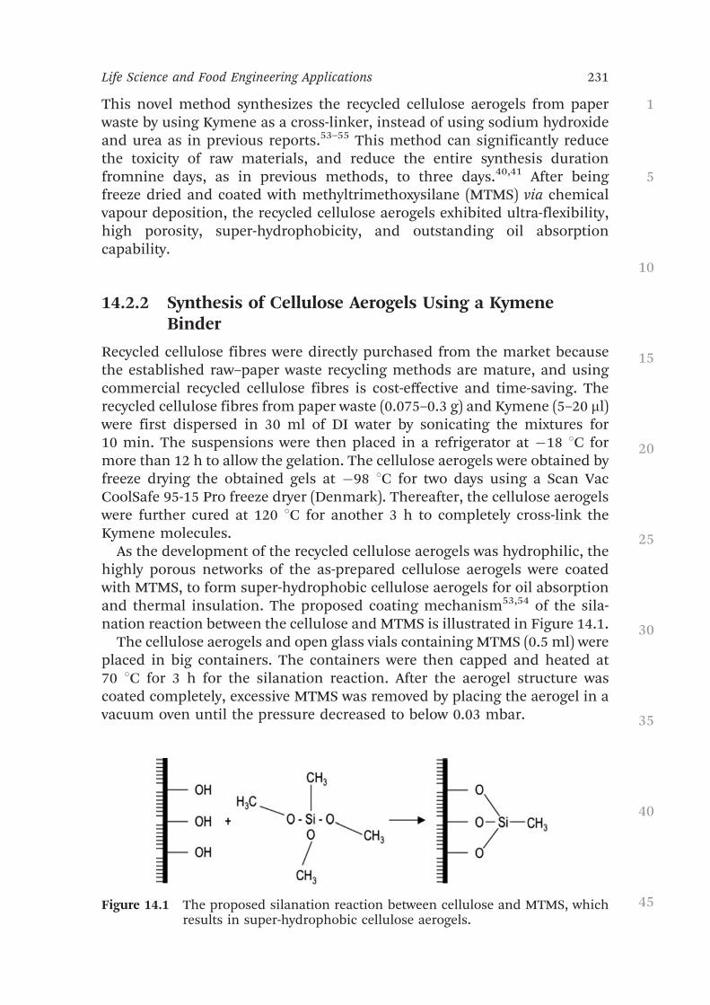
Table 14.1 Chemical compositions of the various recycled celluloseaerogels. (Reprinted from Chemical Engineering Journal, 270,J. Feng, S. T. Nguyen, Z. Fan, H. M. Duong, Advanced fabri-cation and oil absorption properties of superhydrophobicrecycled cellulose aerogels, 168–175, Copyright 2015, withpermission from Elsevier).
Sample label Cellulose fibres (wt.%) Kymene (ml) Porosity (%)
Sample A 0.25 5 99.4# 0.0Sample B 0.50 5 98.9# 0.0Sample C 0.75 5 98.1# 0.0Sample D 1.00 5 97.2# 0.1Sample E 0.60 5 98.4# 0.0Sample F 0.60 20 98.4# 0.0Sample G 1.00 10 97.4# 0.0Sample H 2.00 20 96.9# 0.0Sample I 4.00 40 96.1# 0.3
1
5
10
15
20
25
30
35
40
45
234 Chapter 14

instead of crude oils, as it aims to show the excellent absorptionproperties of cellulose aerogels with oil products containing additives.
When the Kymene amount was kept at 5 ml and the cellulose concen-tration was increased from 0.25 to 0.50 to 0.75 to 1.00 wt.%, the measuredabsorption capacities of the aerogels (Samples A, B, C, and D in Table 14.1)were 95, 73, 58, and 49 g g!1, respectively, at 25 1C. The maximumabsorption capacity of 95 g g!1 was achieved with the 0.25 wt.% celluloseaerogel, because it had the lowest density (9"10!3 g cm!3) and the highestporosity (99.4%).
The absorption capacities of all the MTMS-coated cellulose aerogels wereone order greater than those of the natural sorbents, two to ten times greaterthan those of the commercial polypropylene sorbents, and five timesgreater than those of the recycled cellulose aerogels (approximately 20 g g!1)reported in previous works that used the sodium hydroxide/ureamethod.11,19,25,40,41 The significant enhancement of the absorption capacitymay be largely ascribed to the reduced densities and increased porosities ofthe cellulose aerogels.
The cellulose aerogels fabricated with a Kymene binder can achieve a highporosity (up to 99.4%), while the cellulose aerogels using sodium hydroxideand urea can achieve only 98.0% porosity. When the cellulose amounts werefurther decreased in the syntheses mixture using sodium hydroxide andurea, rigid aerogels could not be successfully formed.
Temperature is also a major factor affecting the viscosity and the diffusioncapability of the oils into the porous aerogel structures. Therefore, theabsorption behaviour of the different oils with each aerogel were examinedat three different temperatures of 25, 50, and 70 1C. As shown in Table 14.2and Figure 14.4, the maximum oil absorption capacity increased when thetemperature was increased from 25 to 50 1C, but then decreased whenthe temperature was further increased from 50 to 70 1C. This trend holdsfor the absorption behaviour of all the oils with the 0.50, 0.75, and 1.00 wt.%cellulose aerogels.
The explanation for this may be that the temperature increase reduced theoil viscosities (shown in Table 14.3), which in turn facilitated oil penetrationinto the porous aerogel networks. However, the lower viscosities of the oilsalso had a negative effect on their ability to anchor to the pore walls,reducing the amounts of oil retained in the porous absorbents duringdrainage. Comparing the maximum oil absorption capacity with the testedtemperatures, it can be concluded that 50 1C is the optimum temperaturefor maximizing the oil absorption performance of the recycled celluloseaerogels.
Besides the temperature effects, the porosity of cellulose aerogels alsosignificantly affects their oil absorbency. Table 14.2 and Figure 14.4 showthat the oil absorption capacity of the aerogels was reduced when the initialcellulose concentration increased from 0.50 to 1.00 wt.%. This can beexplained by the porosity of the cellulose aerogels. Table 14.1 shows thatthe aerogel porosity reduced from 98.9 to 97.2% when the cellulose
1
5
10
15
20
25
30
35
40
45
Life Science and Food Engineering Applications 235

Tabl
e14
.2Su
mm
ary
ofth
em
axim
umoi
lab
sorp
tion
capa
citi
esan
dth
eab
sorp
tion
rate
con
stan
tsof
the
cellu
lose
aero
gels
atdi
ffer
ent
tem
pera
ture
s,w
ith
vari
ous
cellu
lose
fibr
eco
nce
ntr
atio
ns,
usin
gth
eps
eudo
-fir
st-o
rder
and
pseu
do-s
econ
d-or
der
mod
els.
(Rep
rin
ted
from
Che
mic
alEn
gine
erin
gJo
urna
l,27
0,J.
Feng
,S.T
.Ngu
yen,
Z.Fa
n,H
.M.D
uong
,Adv
ance
dfa
bric
atio
nan
doi
lab
sorp
tion
prop
erti
esof
supe
rhyd
roph
obic
recy
cled
cellu
lose
aero
gels
,16
8–17
5,C
opyr
igh
t20
15,w
ith
perm
issi
onfr
omEl
sevi
er).
Cel
lulo
seco
nce
ntr
atio
n(w
t.%)
0.50
0.75
1.00
Tem
pera
ture
(1C
)25
5070
2550
7025
5070
5w50
mot
oroi
lM
axim
umab
sorp
tion
capa
city
,Qm
(gg!
1 )62
.664
.959
.248
.153
.846
.345
.946
.546
.2
Pseu
do-f
irst
-ord
erR
20.
986
0.97
00.
972
0.97
70.
954
0.96
60.
986
0.99
30.
944
K1
0.29
30.
324
0.35
50.
254
0.31
90.
367
0.21
80.
287
0.35
7Ps
eudo
-sec
ond-
orde
rR
20.
996
0.99
60.
998
0.99
50.
998
0.99
60.
996
0.99
50.
998
K2
0.00
60.
008
0.00
90.
008
0.01
00.
015
0.00
50.
007
0.01
3
Sin
ger
mac
hin
eoi
lM
axim
umab
sorp
tion
capa
city
,Qm
(gg!
1 )59
.361
.058
.246
.148
.847
.640
.443
.142
.4
Pseu
do-f
irst
-ord
erR
20.
983
0.97
80.
980
0.98
10.
956
0.99
40.
978
0.97
00.
987
K1
0.29
70.
311
0.35
10.
273
0.30
60.
343
0.27
80.
377
0.42
5Ps
eudo
-sec
ond-
orde
rR
20.
994
0.99
90.
999
0.99
60.
995
0.99
90.
993
0.99
40.
996
K2
0.00
80.
010
0.01
20.
008
0.01
10.
015
0.00
70.
009
0.01
6 1
5
10
15
20
25
30
35
40
45
236 Chapter 14

concentration increased from 0.50 to 1.00 wt.%. As the aerogel porositywas lower, there was less space in the aerogel network for oil occupation,and therefore the oil absorbency was lower.
To evaluate the practical oil absorption performance of the recycledcellulose aerogels in the sea, a 3.5% NaCl solution was prepared to imitateseawater. Figure 14.5 illustrates the absorption process over several minutes.
Figure 14.4 Maximum absorption capacities, Qm, of (a) the 5w50 motor oil and(b) the Singer machine oil with the recycled cellulose aerogels withvarious cellulose fibre concentrations of 0.50, 0.75, and 1.00 wt.% at25, 50, and 70 1C.(Reprinted from Chemical Engineering Journal, 270, J. Feng, S. T.Nguyen, Z. Fan, H. M. Duong, Advanced fabrication and oil absorptionproperties of superhydrophobic recycled cellulose aerogels, 168–175,Copyright 2015,with permission from Elsevier).
1
5
10
15
20
25
30
35
40
45
Life Science and Food Engineering Applications 237

The cellulose aerogel was loaded on top of the mixture, and quickly absorbedmost of the motor oil within 7 min.
In addition, the effects of pH on the oil absorption capacities of thecellulose aerogels were investigated using different pH values prepared fromHCl or NaOH. The oil absorption capacities of the 0.50 wt.% celluloseaerogels under pH¼ 3, 5, 7, and 9 environments were measured to be 63.00,62.85, 63.06, and 62.98 g g!1, respectively. The absorption results indicatedpH-insensitive behaviour of the aerogels during the oil absorption tests,possibly because the oil capacities of aerogels are mostly controlled bytheir porosities and tested oil viscosities, both of which are independentof environmental pH values.
14.2.3.3.2 Absorption Kinetics with Different Oils. The absorption kin-etics of the 5w50 motor oil and Singer machine oil on recycled cellulose
Table 14.3 The relevant viscosities of the tested oils at differenttemperatures. (Reprinted from Chemical EngineeringJournal, 270, J. Feng, S. T. Nguyen, Z. Fan, H. M.Duong, Advanced fabrication and oil absorption prop-erties of superhydrophobic recycled cellulose aerogels,168–175, Copyright 2015, with permission from Elsevier).
Viscosity (Pa.s) 25 1C 50 1C 70 1C5w40 motor oil 0.140 n.a. n.a.5w50 motor oil 0.160 0.054 0.029Singer machine oil 0.026 0.009 0.006
Figure 14.5 Oil absorption process of the recycled cellulose aerogel with 0.5 wt.% ofcellulose fibres in artificial seawater (3.5 wt.% NaCl and pH¼ 7) mixedwith 5w40 motor oil and dyed with Sudan Red G before testing.(Reprinted from Chemical Engineering Journal, 270, J. Feng, S. T.Nguyen, Z. Fan, H. M. Duong, Advanced fabrication and oil absorptionproperties of superhydrophobic recycled cellulose aerogels, 168–175,Copyright 2015,with permission from Elsevier).
1
5
10
15
20
25
30
35
40
45
238 Chapter 14
aerogels were investigated, and are summarized in Table 14.2. Althoughsample A, with a cellulose fibre concentration of 0.25 wt.% (Table 14.1),had the highest oil absorption capacity, it possessed a less rigid structureand was easy to disintegrate after repeated draining and absorbing ofoil. Therefore, three different aerogel samples, marked B, C, and D(Table 14.1) and with cellulose fibre concentrations of 0.50, 0.75, and 1.00wt.% respectively, were prepared for the oil absorption kinetics tests at25 1C. As shown in Figure 14.6, the sorption capacity of each oil on thecellulose aerogels was plotted as a function of absorption time. The sorp-tion rate was fast during the first 10 s, and the absorption reached theequilibrium state at 30 s for both of the two oils.
Figure 14.7 shows the absorption kinetics60,61 of the 5w50 motor oil andSinger machine oil on the 0.50 wt.% cellulose aerogel at 25 1C, respectively.The plots of ln[Qm/(Qm!Qt)] versus time t using the pseudo-first-ordermodel pseudo-second-order models yield the sorption rate constantsk1 and k2, and the correlation coefficient R2 are presented in Table 14.2. Itcan be observed that the correlation coefficient values of the pseudo-second-order model are higher than those of the pseudo-first-order model for bothtested oils. Therefore, the pseudo-second-order model could better predictthe oil absorption behaviour. Most of the absorption rate constants (k1 andk2) for the Singer oil were bigger than those for the 5w50 motor oil. Inaddition, the absorption rate constants at a higher temperature were largerthan those of the same oil and sample at a lower temperature. These suggestthe oil absorption processes of the Singer oil, and those at the higher tem-perature occur faster. Figures 14.7a and b show the experimental absorptionkinetics data and the two fitted model curves for the absorption of the twooils on the 0.50 wt.% cellulose aerogels, which show a good agreement.60,61
The values of k1 and k2 are generally much larger than those reported. Thisphenomenon indicates that the absorption speed of the cellulose aerogelsdescribed in this section, with 5w50 motor oil and Singer oil, were muchhigher than those of the cellulose aerogels described with crude oils. Thismay be explained by the high porosities of the cellulose aerogels.
The activation energy, Ea, is an important parameter in a thermodynamicstudy.62 For example, during a successful absorption process, the activationenergy must be overcome by an absorbate to interact with functional groupson the sorbent surface. The activation energy, Ea, can be determined fromthe change in the absorption rate constant, k, with temperature, T (K), usingthe Arrhenius equation:62,63
lnk¼ ln A! Ea
RT(14:1)
in which A is the pre-exponential factor and R is the gas constant(8.314 J mol!1 K!1). By plotting ln[k] against 1/T, Ea can be calculated fromthe slope.
The activation energy values are presented in Table 14.4. It can be ob-served that the activation energy values of the pseudo-second-order model
1
5
10
15
20
25
30
35
40
45
Life Science and Food Engineering Applications 239

are higher than those of the pseudo-first-order model. This is because thepseudo-second-order model was used for the absorption process controlledby chemi-sorption, which involves higher forces than in physic-sorption.64
Figure 14.6 Absorption kinetics of (a) the 5w50 motor oil and (b) the Singermachine oil on the recycled cellulose aerogels with various cellulosefibre concentrations of 0.50, 0.75, and 1.00 wt.% at 25 1C. The magni-fied images show the absorption kinetics of the initial 2 min of theabsorption processes.(Reprinted from Chemical Engineering Journal, 270, J. Feng, S. T.Nguyen, Z. Fan, H. M. Duong, Advanced fabrication and oil absorptionproperties of superhydrophobic recycled cellulose aerogels, 168–175,Copyright 2015,with permission from Elsevier).
1
5
10
15
20
25
30
35
40
45
240 Chapter 14
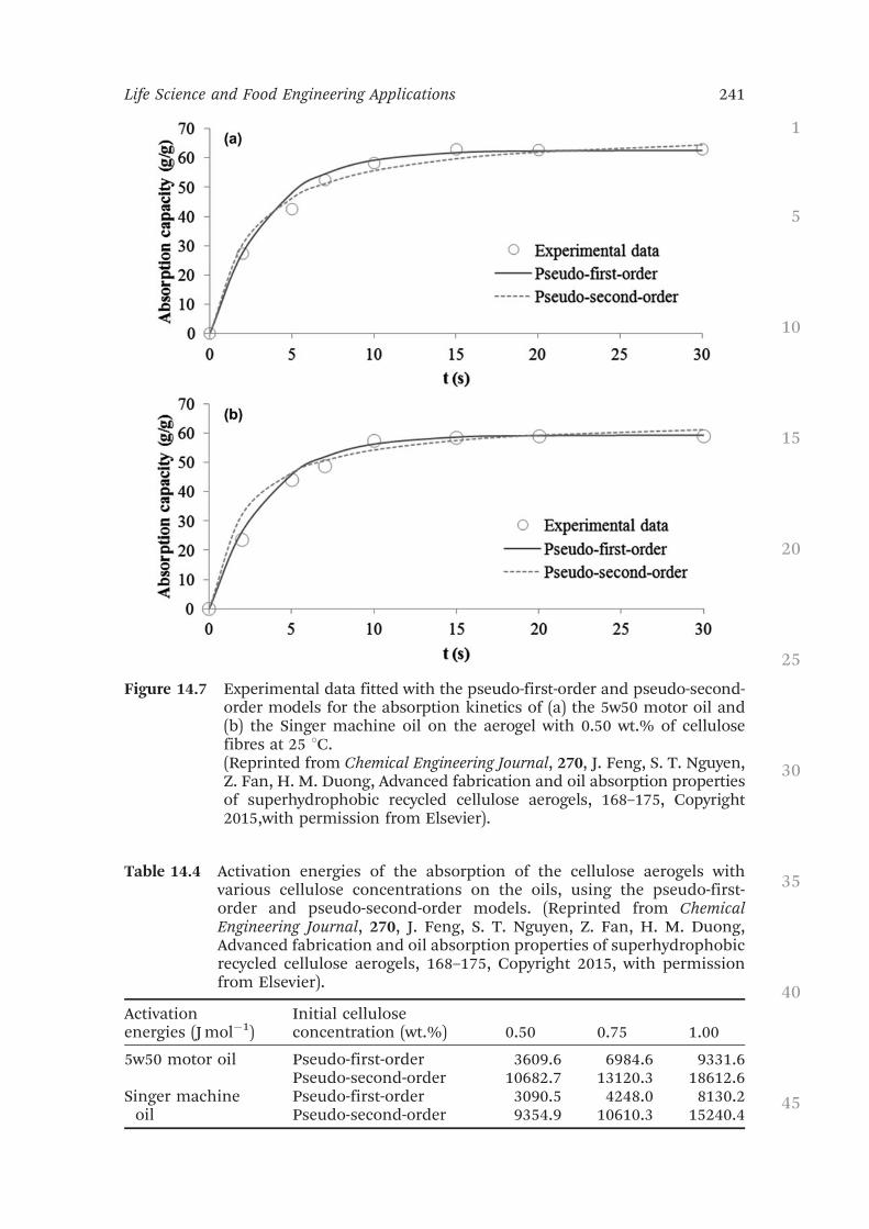
Figure 14.7 Experimental data fitted with the pseudo-first-order and pseudo-second-order models for the absorption kinetics of (a) the 5w50 motor oil and(b) the Singer machine oil on the aerogel with 0.50 wt.% of cellulosefibres at 25 1C.(Reprinted from Chemical Engineering Journal, 270, J. Feng, S. T. Nguyen,Z. Fan, H. M. Duong, Advanced fabrication and oil absorption propertiesof superhydrophobic recycled cellulose aerogels, 168–175, Copyright2015,with permission from Elsevier).
Table 14.4 Activation energies of the absorption of the cellulose aerogels withvarious cellulose concentrations on the oils, using the pseudo-first-order and pseudo-second-order models. (Reprinted from ChemicalEngineering Journal, 270, J. Feng, S. T. Nguyen, Z. Fan, H. M. Duong,Advanced fabrication and oil absorption properties of superhydrophobicrecycled cellulose aerogels, 168–175, Copyright 2015, with permissionfrom Elsevier).
Activationenergies (J mol!1)
Initial celluloseconcentration (wt.%) 0.50 0.75 1.00
5w50 motor oil Pseudo-first-order 3609.6 6984.6 9331.6Pseudo-second-order 10682.7 13120.3 18612.6
Singer machineoil
Pseudo-first-order 3090.5 4248.0 8130.2Pseudo-second-order 9354.9 10610.3 15240.4
1
5
10
15
20
25
30
35
40
45
Life Science and Food Engineering Applications 241

In addition, compared with the 5w50 motor oil, the Singer machine oilhad lower activation energy values, which made the oil absorption on thecellulose aerogels more effective.
14.2.4 Summary
In conclusion, the advanced and cost-effective fabrication method of therecycled cellulose aerogels was further improved. The MTMS-coated cellu-lose aerogels exhibited stable hydrophobicity during a test period of overfive months. Their excellent oil absorption capacities were demonstratedwith motor oil and Singer oil. It was found that the initial cellulose fibreconcentration significantly affected the oil absorption capability of the de-veloped cellulose aerogels. The 0.25 wt.% cellulose aerogel yielded a max-imum absorption capacity of 95 g g!1 with the 5w40 motor oil. Themaximum absorption capacity of the cellulose aerogels could be reachedat 50 1C, regardless of the pH values of the seawater/oil suspensions, anddecreased with an increase in the cellulose fibre concentration.
The pseudo-first-order and pseudo-second-order kinetics models wereapplied to describe the oil absorption behaviour of the recycled celluloseaerogels for the first time. The pseudo-second-order model was more suitedto the oil absorption kinetics study of the aerogels, due to its chemi-sorptionnature. Moreover, the recycled cellulose aerogels displayed excellent flexi-bility: the large-scale cellulose aerogel could be easily bent or rolled withoutdamaging its shape. All of the tested cellulose aerogels could also be com-pressed to up to 70% strain. The experimental results demonstrate thatthe super-hydrophobic recycled cellulose aerogels could be very promisingsorbents for oil-spill cleaning.
14.3 Cellulose-based Aerogels for Heat-insulationApplications
14.3.1 Introduction
The greenhouse effect is gradually warming up the earth and potentiallythreatening human life. It was found that CO2 emissions from buildingscontributed approximately 31% of global greenhouse-gas emissions in2010.65,66 Improving thermal insulation of buildings is one of the mosteffective solutions for this issue. Therefore, many efforts have been madeto develop new insulation materials.67 Silica aerogels have been investigatedas insulation materials for buildings.68 However, they are very brittle.A flexible, aerogel-based insulation material has been developed by AspenAerogels (USA), but it is much more expensive than conventional insulationmaterials.68 As a result, there is considerable need for insulation materialswith reasonably low thermal conductivities and costs. These materialsshould also have high thermal stability for fire safety.
1
5
10
15
20
25
30
35
40
45
242 Chapter 14

This section focuses on the thermal properties, such as thermal conduct-ivity and thermal stability, of the recycled cellulose aerogels and their silicacomposites.69 This is the first time that the benchmark data of the thermalproperties of recycled cellulose-based aerogels has been reported. Of the re-cycled cellulose-based materials, the recycled cellulose aerogels using sodiumhydroxide–urea aqueous solutions showed the lowest thermal conductivities(0.032 W mK!1); however, the cellulose aerogels display a continuousweight loss from below 100 1C, during the thermogravimetric (TGA) test.The cellulose–silica composite aerogels displayed the best thermal stability;however, their thermal conductivities (0.039–0.041 W mK!1) are much higherthan those of the cellulose aerogels using sodium hydroxide–urea aqueoussolutions (0.032 W mK!1). In summary, the recycled cellulose aerogels using aKymene binder (the aerogels with the lowest cost), exhibit lower thermalconductivities (0.034–0.037 W mK!1) than those of the composite aerogels(0.039–0.041 W mK!1), and a higher thermal stability (with a decompositiontemperature of approximately 300 1C) surpassing that of the cellulose aerogelsusing sodium hydroxide–urea aqueous solutions. The recycled celluloseaerogels are therefore the most promising thermal insulation material.
14.3.2 Synthesis of Silica–Cellulose Aerogels
The catalyst solution was prepared by mixing 10.250 g of ammoniumhydroxide and 0.927 g of ammonium fluoride in 50 ml of deionised (DI)water. After that, 6 ml of MTMS solution was mixed with 11 ml of ethanoland stirred for 5 min (forming an MTMS/ethanol solution). Then, 7 ml ofDI water, 11 ml of ethanol, and 0.5 ml of the catalyst solution were mixed inanother beaker (forming a water/ethanol/catalyst solution). While theMTMS/ethanol mixture was still being stirred, the obtained DI water/ethanol/catalyst solution was poured slowly into the MTMS/ethanol mixtureand stirred for another 15 min to form the sol. The sol was poured into amould that contained the cellulose aerogel, and the gelation and agingprocess were conducted at room temperature (25 1C) for three days. Aftersolvent exchange between the gel and DI water, the obtained hydrogel wasfrozen and dried using a Scan Vac CoolSafe 95-15 Pro freeze dryer (Denmark)for 24 h. Different silica–cellulose aerogels were synthesized from the dif-ferent cellulose aerogel matrixes with varied cellulose fibre concentrationsinside the initial cellulose aqueous suspensions. The fabrication method ofpure recycle cellulose aerogel can be found in the section 14.2.2.
14.3.3 Thermal Properties of the Cellulose-based Aerogels
14.3.3.1 Thermal Properties of the Recycled Cellulose AerogelsUsing a Kymene Binder
The thermal conductivities of the aerogels were measured under ambientconditions using a C-Therm TCi Thermal Conductivity Analyzer (C-Therm
1
5
10
15
20
25
30
35
40
45
Life Science and Food Engineering Applications 243

Technologies, Canada), with the MTPS method. Using this approach, thethermal conductivities of the recycled cellulose aerogels fabricated with aKymene binder were measured. The porosity of the cellulose aerogels using aKymene binder significantly affected their thermal conductivities. Table 14.5shows that the thermal conductivity of the aerogels using a Kymene binderincreased from 0.034 to 0.037 W mK!1 when the initial cellulose fibre con-centration increased from 1.0 to 4.0 wt.%. Increases in the initial cellulosefibre concentration led to decreases in the porosity of the resultant celluloseaerogels. When the porosity is lower, there is more solid substance to pro-mote thermal conduction and reduce thermal insulation.
The thermal stability of the cellulose aerogels using a Kymene binder wasmuch better than that of the cellulose aerogels fabricated from the sodiumhydroxide–urea aqueous solution. A weight loss of 6.5 wt.%, corresponding tothe water release, was observed in the temperature range of 25–150 1C for thecellulose aerogel using a Kymene binder. Slow decomposition of the materialwas observed between 150 and 300 1C, and 86.3 wt.% remained of the cellu-lose aerogel using a Kymene binder at 300 1C. In comparison, 40.7 wt.%remained of the cellulose aerogel fabricated from the sodium hydroxide–ureaaqueous solution at the same temperature. The obvious differences suggestthat the thermal stability of the cellulose aerogel using a Kymene binder wasmuch better than that of the cellulose aerogel synthesized via the sodiumhydroxide–urea route. The differences between the thermal stabilities of thesetwo cellulose aerogels could possibly be explained by two major factors: (1)there was no urea involved in the fabrication of the cellulose aerogels viathe Kymene route, and so there was no urea residue;39 and (2) the sonicationmethod applied with the Kymene route, as a mechanical approach, had anadvantage over the chemical treatment methods regarding thermal stability ofthe cellulose materials.70,71
14.3.3.2 Thermal Properties of the Silica–Cellulose Aerogels
The silica–cellulose composite aerogels were fabricated by immersing thecellulose matrixes inside the solutions containing a silica precursor.The cellulose matrixes were the recycled cellulose aerogels (obtained after
Table 14.5 Effects of cellulose fibre concentrations on the thermalconductivities of the cellulose aerogels using a Kymenebinder. (Reprinted from Colloids and Surfaces A: Physicochem-ical and Engineering Aspects, 506, J. Feng, D. Le, S. T. Nguyen,V. T. C. Nien, D. Jewell, H. M. Duong, Silica cellulose hybridaerogels for thermal and acoustic insulation applications,298–305, Copyright 2016, with permission from Elsevier).
Cellulose fibreconcentration (wt.%) Density (g cm!3)
Thermal conductivity(W mK!1)
1.0 0.0392# 0.0005 0.0340# 0.00032.0 0.0473# 0.0004 0.0353# 0.00064.0 0.0592# 0.0032 0.0366# 0.0003
1
5
10
15
20
25
30
35
40
45
244 Chapter 14

hydrophobic coating) fabricated with a Kymene binder. The main purposeof the development of the silica–cellulose aerogels was to further improvethe thermal stability and mechanical strength of the pure cellulose aerogels.The different silica–cellulose aerogels were synthesized from the variedcellulose matrixes with different initial recycled cellulose fibre concen-trations (1.0–4.0 wt.%) in the initial cellulose suspensions.
14.3.3.2.1 Morphology and Hydrophobicity of the Silica–Cellulose Aero-gels. The morphologies of the silica–cellulose composite aerogels wereinvestigated with FE-SEM. Figure 14.8a–c display the SEM images of thesilica–cellulose aerogels fabricated with the cellulose matrixes with differ-ent cellulose fibre concentrations in the initial cellulose aqueous suspen-sions. The images in Figure 14.8a–c suggest that the cellulose matrixserved as the three-dimensional supporting frame.
The intersection points between the cellulose fibres were strengthened by agreat number of hydrogen-bond links, which helped the formation of thestrong supporting frame.72 The strong supporting frame restricted the silicaparticles firmly within it by a confinement effect.73 Meanwhile, the inter-connected silica particles reinforced the cellulose matrix by attaching them-selves to the matrix. As a result, a more rigid structure was formed. Thestructures of the silica–cellulose aerogels using different cellulose aerogel
Figure 14.8 SEM images of the silica–cellulose aerogels fabricated with the cellulosematrixes with different cellulose fibre concentrations (a) 1.0 wt.%,(b) 2.0 wt.%, and (c) 4.0 wt.% in the initial cellulose aqueous suspensions.(d) A typical image of the zoomed-in silica region of the composites.(Reprinted from Colloids and Surfaces A: Physicochemical and EngineeringAspects, 506, J. Feng, D. Le, S. T. Nguyen, V. T. C. Nien, D. Jewell, H. M.Duong, Silica cellulose hybrid aerogels for thermal and acousticinsulation Applications, 298–305, Copyright 2016, with permission fromElsevier).
1
5
10
15
20
25
30
35
40
45
Life Science and Food Engineering Applications 245
matrixes were compared. When the cellulose content was higher, silica par-ticles with a smaller particle size and more uniform distribution were found.This phenomenon might be explained by the following speculation. Beforethe freeze drying, the cellulose fibres were embedded in the silica hydrogel.During the freeze drying (including the freezing pre-treatment), the silicaparticles further away from the cellulose fibres experienced less force fromthe cellulose matrix than the silica particles next to the cellulose fibres. Thedenser cellulose matrix led to a more uniform distribution of small silicaparticles because of the more uniformly distributed force exerted by the cel-lulose matrix. On the other hand, the loose cellulose matrix with many largepores yielded a number of large silica particles located away from the cellulosefibres because of the small force exerted by the cellulose matrixes. At the sametime, inside the loose cellulose matrix, the large silica particles located awayfrom the cellulose fibres coexisted with the small silica particles that formednear the cellulose fibres, yielding a less uniform distribution.
The mesostructure of the silica particles was similar to the findings ofother groups that developed silica–cellulose aerogels.73,74 The BET surfaceareas of the silica–cellulose composite aerogels in Table 14.6 were betweenapproximately 198 and 296 m2 g!1, comparable to the surface areas found insimilar studies conducted by Demilecamps et al. (90–170 m2 g!1)75 andLitschauer et al. (220–290 m2 g!1).76
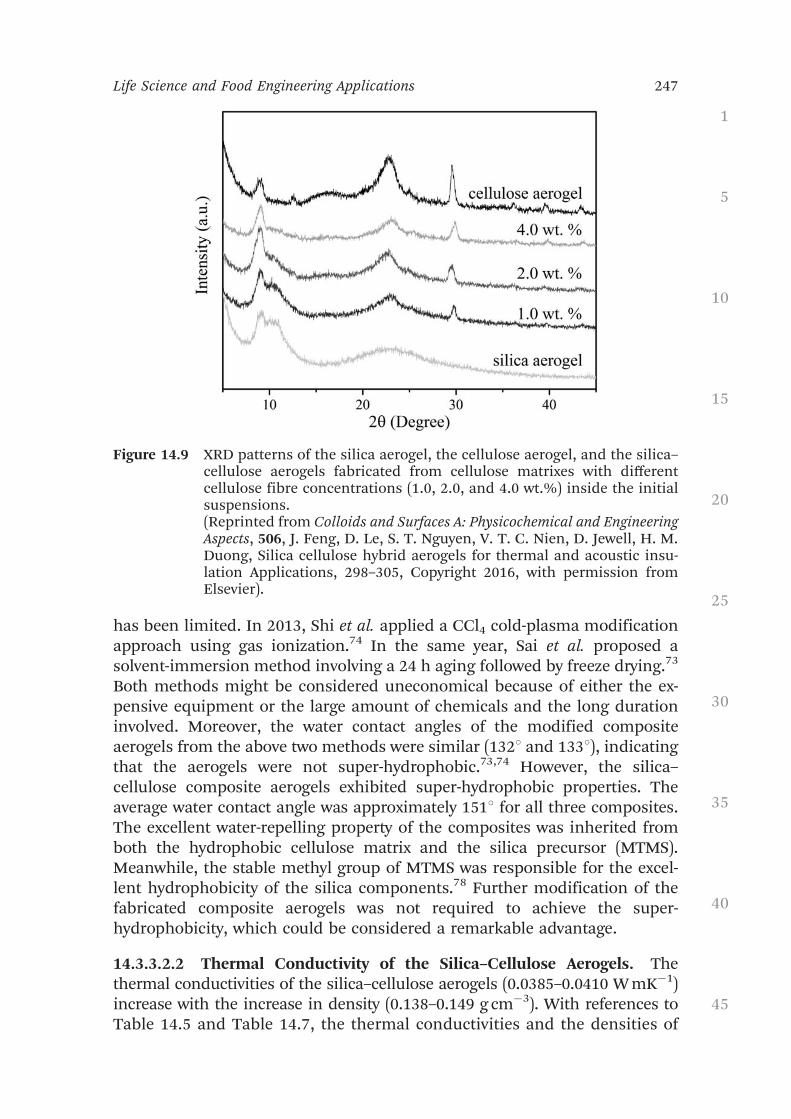
As can be observed in Figure 14.9, the X-ray diffraction patterns of thesilica–cellulose composite aerogels seem to be the superposition of those ofthe pure cellulose aerogels and the pure silica aerogels, which is similar tothe findings of Cai et al.77 This XRD finding implies that the extent of thechemical reaction between the cellulose fibres and the silica componentswas quite limited, as no new compound was detected. The XRD resultssuggest that it was reasonable for the meso-porous structure of the silica–cellulose aerogels to be controlled only by the silica components as thecellulose matrix did not possess a detectable BET surface area, and no newcompound was formed. In addition, the XRD results indicate that theattachments between the cellulose fibres and the silica particles observed inthe SEM images were physical instead of chemical.
According to Shi et al., the hydrophobicity of the composite could improvethe stability of the heat-insulation performance of the material.74 To date,research on hydrophobic modifications of silica–cellulose composite aerogels
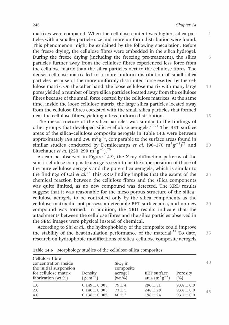
Table 14.6 Morphology studies of the cellulose–silica composites.
Cellulose fibreconcentration insidethe initial suspensionfor cellulose matrixfabrication (wt.%)
Density(g cm!3)
SiO2 incompositeaerogel(wt.%)
BET surfacearea (m2 g!1)
Porosity(%)
1.0 0.149# 0.005 79# 4 296# 31 93.8# 0.02.0 0.146# 0.005 73# 5 248# 28 93.8# 0.04.0 0.138# 0.002 60# 3 198# 24 93.7# 0.0
1
5
10
15
20
25
30
35
40
45
246 Chapter 14
has been limited. In 2013, Shi et al. applied a CCl4 cold-plasma modificationapproach using gas ionization.74 In the same year, Sai et al. proposed asolvent-immersion method involving a 24 h aging followed by freeze drying.73
Both methods might be considered uneconomical because of either the ex-pensive equipment or the large amount of chemicals and the long durationinvolved. Moreover, the water contact angles of the modified compositeaerogels from the above two methods were similar (1321 and 1331), indicatingthat the aerogels were not super-hydrophobic.73,74 However, the silica–cellulose composite aerogels exhibited super-hydrophobic properties. Theaverage water contact angle was approximately 1511 for all three composites.The excellent water-repelling property of the composites was inherited fromboth the hydrophobic cellulose matrix and the silica precursor (MTMS).Meanwhile, the stable methyl group of MTMS was responsible for the excel-lent hydrophobicity of the silica components.78 Further modification of thefabricated composite aerogels was not required to achieve the super-hydrophobicity, which could be considered a remarkable advantage.
14.3.3.2.2 Thermal Conductivity of the Silica–Cellulose Aerogels. Thethermal conductivities of the silica–cellulose aerogels (0.0385–0.0410 W mK!1)increase with the increase in density (0.138–0.149 g cm!3). With references toTable 14.5 and Table 14.7, the thermal conductivities and the densities of
Figure 14.9 XRD patterns of the silica aerogel, the cellulose aerogel, and the silica–cellulose aerogels fabricated from cellulose matrixes with differentcellulose fibre concentrations (1.0, 2.0, and 4.0 wt.%) inside the initialsuspensions.(Reprinted from Colloids and Surfaces A: Physicochemical and EngineeringAspects, 506, J. Feng, D. Le, S. T. Nguyen, V. T. C. Nien, D. Jewell, H. M.Duong, Silica cellulose hybrid aerogels for thermal and acoustic insu-lation Applications, 298–305, Copyright 2016, with permission fromElsevier).
1
5
10
15
20
25
30
35
40
45
Life Science and Food Engineering Applications 247

the silica–cellulose aerogels (0.0385–0.0410 W mK!1; 0.138–0.149 g cm!3)were higher than those of the cellulose aerogels using a Kymene binder(0.034–0.037 W mK!1; 0.039–0.059 g cm!3). One possible reason is that thethermal conductivities increase with density.79,80 The thermal conduct-ivities of the silica–cellulose aerogels (0.0385–0.0410 W mK!1) were lowerthan those of the silica–cellulose composites fabricated by other groups(0.15 W mK!1), and comparable to those of conventional insulation ma-terials, such as polyurethane foams (0.02–0.04 W mK!1) and insulationboards (0.035–0.16 W mK!1).81
As shown in Figure 14.10, it is clear that the thermal stability of the com-posite was better than that of the pure cellulose aerogel without the silica
Table 14.7 The thermal conductivities of the silica–cellulose aerogels fabricatedfrom cellulose matrixes with different cellulose fibre concentrations inthe initial suspensions. (Reprinted from Colloids and Surfaces A: Physi-cochemical and Engineering Aspects, 506, J. Feng, D. Le, S. T. Nguyen, V. T.C. Nien, D. Jewell, H. M. Duong, Silica cellulose hybrid aerogels forthermal and acoustic insulation Applications, 298–305, Copyright 2016,with permission from Elsevier).
Cellulose fibre concentrationin the initial suspension forcellulose-matrix fabrication (wt.%) Density (g cm!3)
Thermal conductivity(W mK!1)
1.0 0.149# 0.005 0.0410# 0.00032.0 0.146# 0.005 0.0390# 0.00064.0 0.138# 0.002 0.0387# 0.0003
Figure 14.10 The thermogravimetric analysis (TGA) curve of the silica–celluloseaerogel, compared with that of the cellulose aerogel using a Kymenebinder. The composite aerogels were fabricated from cellulosematrixes with different cellulose fibre concentration of 4.0 wt.% inthe initial suspensions.
1
5
10
15
20
25
30
35
40
45
248 Chapter 14

embedment. A small weight loss of approximately 2 wt.% of the compositesbefore 150 1C corresponds to the water release. The cellulose aerogel using aKymene binder showed an approximately 7 wt.% weight loss up to 150 1C,which is greater than that of the composite. This smaller weight loss from thedesorbed water was due to the super-hydrophobicity of the composite.
A 25 1C delay in the thermal degradation of the cellulose component of thecomposite was observed at 325 1C, compared with 300 1C before the silicamodification. This increase in the degradation temperature might have beendue to an interaction between the silica and the cellulose matrix at highertemperatures, and the interaction showed a positive effect on the thermalresistance of the composite.81,82 At 300 1C, 93 wt.% silica–cellulose aerogelsremained, as opposed to 86 wt.% of cellulose aerogels using the Kymenebinder, demonstrating a better thermal stability. The slow mass loss of theresidual substances, followed the rapid oxidative decomposition stage,after which the oxidation of the charred residue occurred and continued tothe plateau. At the plateau, 51 wt.% of the silica–cellulose aerogel waspreserved, mainly containing the silica.
14.3.3.2.3 Mechanical Properties of the Silica–Cellulose Aerogels. Thesilica modification did not impede the ductile behaviour of the silica–cellulose aerogels. The compressive strain–stress curves of the silica–celluloseaerogels fabricated from different cellulose matrixes are displayed inFigure 14.11.
Figure 14.11 The compressive strain–stress curves of the silica–cellulose aerogelsfabricated from the cellulose matrixes with different cellulose fibreconcentrations (1.0, 2.0, and 4.0 wt.%) in the initial suspensions.The magnified section shows the compressive curves at the low strain(up to 5%) for the composite aerogels.
1
5
10
15
20
25
30
35
40
45
Life Science and Food Engineering Applications 249
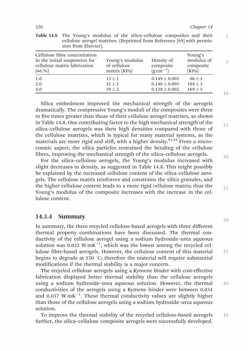
Silica embedment improved the mechanical strength of the aerogelsdramatically. The compressive Young’s moduli of the composites were threeto five times greater than those of their cellulose aerogel matrixes, as shownin Table 14.8. One contributing factor to the high mechanical strength of thesilica–cellulose aerogels was their high densities compared with those ofthe cellulose matrixes, which is typical for many material systems, as thematerials are more rigid and stiff, with a higher density.83,84 From a micro-cosmic aspect, the silica particles restrained the bending of the cellulosefibres, improving the mechanical strength of the silica–cellulose aerogels.
For the silica–cellulose aerogels, the Young’s modulus increased withslight decreases in density, as suggested in Table 14.8. This might possiblybe explained by the increased cellulose content of the silica–cellulose aero-gels. The cellulose matrix reinforces and constrains the silica granules, andthe higher cellulose content leads to a more rigid cellulose matrix; thus theYoung’s modulus of the composite increases with the increase in the cel-lulose content.
14.3.4 Summary
In summary, the three recycled cellulose-based aerogels with three differentthermal property combinations have been discussed. The thermal con-ductivity of the cellulose aerogel using a sodium hydroxide–urea aqueoussolution was 0.032 W mK!1, which was the lowest among the recycled cel-lulose fibre-based aerogels. However, the cellulose content of this materialbegins to degrade at 150 1C; therefore the material will require substantialmodifications if the thermal stability is a major concern.
The recycled cellulose aerogels using a Kymene binder with cost-effectivefabrication displayed better thermal stability than the cellulose aerogelsusing a sodium hydroxide–urea aqueous solution. However, the thermalconductivities of the aerogels using a Kymene binder were between 0.034and 0.037 W mK!1. These thermal conductivity values are slightly higherthan those of the cellulose aerogels using a sodium hydroxide–urea aqueoussolution.
To improve the thermal stability of the recycled cellulose-based aerogelsfurther, the silica–cellulose composite aerogels were successfully developed.
Table 14.8 The Young’s modulus of the silica–cellulose composites and theircellulose aerogel matrixes. (Reprinted from Reference [69] with permis-sion from Elsevier).
Cellulose fibre concentrationin the initial suspension forcellulose matrix fabrication(wt.%)
Young’s modulusof cellulosematrix (KPa)
Density ofcomposite(g cm!3)
Young’smodulus ofcomposite(KPa)
1.0 13# 1 0.149# 0.005 86# 32.0 21# 1 0.146# 0.005 104# 34.0 39# 2 0.138# 0.002 169# 5
1
5
10
15
20
25
30
35
40
45
250 Chapter 14

A 25 1C delay in the cellulose degradation was also observed for the com-posites. The developed silica–cellulose aerogels also had better mechanicalstrengths (compressive Young’s modulus: 86–169 KPa) than those of thecellulose aerogels (compressive Young’s modulus: 13–39 KPa). Moreover, theinherent super-hydrophobic property of the silica–cellulose aerogels is alsodesirable for reliable and long-term thermal insulation. The thermal con-ductivities of the silica–cellulose aerogels were approximately 0.04 W mK!1,comparable to those of commercial insulation products and lower thanthose of the cellulose aerogels.
14.4 Protein-based Aerogels and Their ApplicationsRecently, natural protein-based aerogels have attracted increasing researchinterest due to their biocompatibility and biodegradability for food engin-eering and life science applications. A few proteins such as whey pro-tein,43–45 silk fibroin,46,47 egg white protein,48 and soy protein49–52 have beenexploited for the formation of aerogels. This section introduces the fabri-cation methods and the multi-properties of the different types of protein-based aerogels and their potential applications.
14.4.1 Whey Protein Aerogels
Whey protein is the collection of globular proteins isolated from whey,which is the liquid remaining after milk has been curdled and strained forcheese production. This protein is typically a mixture of beta-lactoglobulin,alpha-lactalbumin, bovine serum albumin and immunoglobulins.85 Wheyprotein is widely used in the food industry applications including processedmeats, bakery products, pasta, ice cream, and infant foods.44,86 As a by-product of the manufacture of cheese or casein, the broad availability inwestern countries makes whey protein promising for environmentallyfriendly-materials.44
Betz et al. developed a novel whey protein-based aerogel for drug deliveryapplications.43 Previous studies indicated that the water-insoluble wheyprotein hydrogels were applicable for the encapsulation of drugs.87,88 Theuse of supercritical drying and freeze drying techniques resulted in thedrying of covalently crosslinked hydrogels and generated a highly porousaerogel. The obtained mechanically stable aerogels possessed a high BET-surface area (310–388 m2 g!1) and drug loading capacity (9.1–9.5%, w/w forketoprofen). The covalent disulphide bonds avoided the collapse of theaerogel structure when placed in the presence of aqueous media and led to apH-controlled swelling behaviour upon rehydration. Due to the water-insolubility of the whey protein aerogels, the drug-loaded aerogels showeda sustained drug release at gastric (pH 1.2) and intestinal (pH 6.8) simulateddigestive pH conditions. Later, Chen et al. prepared whey protein aerogelswith enhanced mechanical properties.44 By blending with alginate, thecompressive moduli of the obtained aerogels were significantly enhanced by
1
5
10
15
20
25
30
35
40
45
Life Science and Food Engineering Applications 251
crosslinking and further increased with increasing aerogel densities.Ahmadi et al. prepared whey protein aerogels blended with nanocrystallineand microcrystalline cellulose particles and achieved increased Young’smodulus and elastic character of the aerogels.45 It was found that the na-nocrystalline and microcrystalline cellulose particles impacted the texture ofwhey protein aerogels to different extents. Blending with cellulose nano-crystalline particles reinforced the texture of protein aerogels and decreasedthe sub-100 nm pore volume. The obtained protein aerogels were furtherapplied for fish oil encapsulation.
14.4.2 Silk Fibroin Aerogels
Silk fibroin is a natural protein, derived from the Bombyx mori silkworm.Due to their biocompatibility and biodegradability, silk fibroin based porousmaterials have been extensively investigated for biomedical applications.47
Marin et al. developed silk fibroin aerogels as drug delivery devices forthe extended release of ibuprofen, a candidate drug.46 Ibuprofen, a candi-date drug compound, was loaded into the silk fibroin aerogels usingsupercritical CO2. The obtained aerogels demonstrated high surface areas of424# 75 m2 g!1 and low densities of 0.058# 0.001 g ml!1. Phosphate buffersolution soaking studies revealed that the silk fibroin aerogels did notswell, nor exhibited any weight loss for up to 6 h. Release of ibuprofen fromSF aerogels was found to be governed by Fickian diffusion.
Later, Mallepally et al. applied silk fibroin aerogels as potential scaffoldsfor tissue engineering applications.47 Silk fibroin aerogel scaffolds weresuccessfully fabricated using sol–gel and supercritical CO2 processingprotocols. The morphology and textural properties of the silk fibroin aero-gels could be tuned by the starting concentration of the silk fibroin aqueoussolution. When the aqueous fibroin concentration increased from 2 to6 wt.%, the surface area of the resultant aerogels increased from 260 to308 m2 g!1 and the compressive modulus increased from 19.5 to 174 kPa.Silk fibroin cryogels were also synthesised, in order to study the effect ofhydrogels pretreatments on the morphological and textural properties.47 Thesilk fibroin aerogels demonstrated a surface area of 266 m2 g!1 and porevolume of 1.6 cc g!1, which was significantly higher compared to the freeze-dried silk fibroin cryogels with a surface area of 45 m2 g!1 and pore volumeof 0.05 cc g!1. These results make these silk fibroin aerogels promising forcell culture and tissue engineering applications. In vitro cell culture studieswith human foreskin fibroblast cells showed that the silk fibroin aerogelswere cytocompatible with human cells and the aerogel scaffold promotedtheir propagation.
14.4.3 Egg White Protein Aerogels
As a high quality protein source with high nutrition, egg white protein offersversatile functional properties and it is widely used in the food industry.89
1
5
10
15
20
25
30
35
40
45
252 Chapter 14

Native egg white consists of about 10 wt.% protein and 90 wt.% water.89
When egg white is heated, the egg white proteins denature thermally andform a gel whose structure is influenced by pH, ionic strength and the typeof added salt.90 Selmer et al. developed egg white protein-based aerogels as acarrier material for food applications.48 The aerogels were prepared by gel-ation of pasteurized and spray-dried egg white solutions and subsequentsupercritical drying. The porosity and surface area of the aerogels could betailored by controlling the pH and ionic strength of the solution during thegelation process. The largest BET-surface area of 380 m2 g!1 was achieved atpH 2, while the most mechanically stable aerogels were obtained at alkalinepH. In order to produce mechanically stable aerogels with high surfaceareas, pH values above the isoelectrical point should be used. These protein-based aerogels were suitable as microencapsulation materials for sensitiveor unpleasant tasting food additives.
14.4.4 Soy Protein Aerogels
Soy flour, as a great source of protein, contains approximately 42% protein,20% oil, 33% carbohydrates, and 5% ash on a dry basis. Protein from soy ismainly composed of acidic amino acids such as aspartic and glutamic acids,non-polar amino acids (glycine, alanine, valine and leucine), basic aminoacids (lysine and arginine), and less than 1% of cysteine.91 The soy protein-based aerogels have been designed for different applications.49–52 Amaral-Labat et al. reported the first natural organic aerogels at the 91% level, whichwere prepared from gelation of tannin–soy flour resin in aqueous solution,followed by supercritical drying in CO2.49 The resultant aerogels presented alow density of 0.19–0.25 g cm!3 and high mesopore volumes up to2.3 cm3 g!1. The pore structures of the aerogels were tuneable by varying thepH values in the synthesis processes. These soy–tannin aerogels have po-tential for various applications, such as catalyst supports, adsorption ofacidic species in liquids or natural super-insulators.
To improve the mechanical properties of the soy protein aerogels, Arbo-leda et al. developed the soy protein–nanocellulose composite aerogels.50
The nanofibrillar cellulose loading resulted in the morphology transition ofthe aerogels from network- to fibrillar-like, with a high density of inter-connected cells. With soy protein loadings as high as ca. 70%, the aerogelsshowed a high compression modulus of 4.4 MPa. The developed aerogelscan absorb water and other solvents while maintaining their integrity. Dueto their low density and good mechanical properties, these soy protein basedaerogels are interesting candidates for applications including packaging,thermal and acoustic insulation, and so forth.
14.5 ConclusionsPaper waste can be successfully converted into cellulose-based aerogelswith high oil absorption capacities (95 g g!1), good thermal-insulation
1
5
10
15
20
25
30
35
40
45
Life Science and Food Engineering Applications 253

performances (0.032 W mK!1), and excellent water-repellent properties(1511). Recycled cellulose-based aerogels utilizing paper waste are prom-ising and economical candidates for several applications, such as oil-spillcleaning and building thermal insulation. In addition, morphologycontrol of the recycled cellulose aerogels could be efficiently achieved bychanging the cellulose concentration. To obtain the hydrophobic coating, asimple but effective chemical vapour deposition method via MTMS wasdeveloped, and the stability of the hydrophobic coating was tested. Therecycled cellulose aerogels generated from both fabrication methodsdemonstrated stable hydrophobic properties over the tested time span offive months.
The initial cellulose fibre concentration played a critical role in the ab-sorption capacities: the decreases in the initial cellulose fibre concen-tration led to increases in the absorption capacities due to the reducedporosities. The optimum temperature for high oil absorption capacity was50 1C (of 25, 50, and 70 1C) because of the favourable viscosities of the oilsat this temperature, as the viscosities were low enough for the oils to ef-ficiently penetrate the porous aerogel networks, and high enough for theoils to effectively anchor to the pore walls of the cellulose aerogels. Inaddition, the pH values of the seawater/oil suspension had negligible ef-fects on the oil absorption capacities of the cellulose aerogels, as the keyfactors affecting absorption capacity (the porosities of the cellulose aero-gels and the viscosities of the oils) were independent of the environmentalpH values.
The most cost-effective cellulose aerogels using a Kymene binder showedan observable improvement in thermal stability over the previous celluloseaerogels, because the Kymene method mainly applies a mechanical ap-proach and no urea is involved. To improve the thermal stability further, thesilica–cellulose aerogels were successfully developed. The major DTA peakalso shifted from 352 1C for the cellulose aerogels to 530–550 1C for thesilica–cellulose aerogels, as the major DTA peak of the composites is causedby the oxidation of the methyl group of the silica component. In addition,the silica–cellulose aerogels displayed an inherent super-hydrophobicproperty and better mechanical strength (Young’s modulus: 86–169 KPa)than the cellulose aerogels using a Kymene binder (4–39 KPa). However, thethermal conductivities (approximately 0.04 W mK!1) of the silica–celluloseaerogels were higher than those of the cellulose aerogels using a Kymenebinder, due to their high density and low porosity.
Protein-based aerogels are novel biodegradable and biocompatiblematerials for lightweight food engineering and life science applications. Thetypes of proteins, initial protein concentrations, processing techniquesand many environmental conditions demonstrate significant influenceson the structures and properties of the resultant aerogels. Further studiesare required to tailor the morphological and textural properties of theseprotein-based aerogels with enhanced mechanical stability for practicalapplications.
1
5
10
15
20
25
30
35
40
45
254 Chapter 14

References1. O. A. Centeno-Chale, M. L. Aguirre-Macedo, G. Gold-Bouchot and
V. M. Vidal-Martınez, Effects of Oil Spill Related Chemical Pollution onHelminth Parasites in Mexican Flounder Cyclopsetta Chittendeni fromthe Campeche Sound, Gulf of Mexico, Ecotoxicol. Environ. Saf., 2015, 119,162–169.
2. D. Li, F. Z. Zhu, J. Y. Li, P. Na and N. Wang, Preparation and Charac-terization of Cellulose Fibers from Corn Straw as Natural Oil Sorbents,Ind. Eng. Chem. Res., 2012, 52(1), 516–524.
3. H. Li, L. Liu and F. Yang, Hydrophobic Modification of PolyurethaneFoam for Oil Spill Cleanup, Mar. Pollut. Bull., 2012, 64(8), 1648–1653.
4. V. Singh, R. J. Kendall, K. Hake and S. Ramkumar, Crude Oil Sorption byRaw Cotton, Ind. Eng. Chem. Res., 2013, 52(18), 6277–6281.
5. J. Wang, Y. Zheng, Y. Kang and A. Wang, Investigation of Oil SorptionCapability of Pbma/Sio 2 Coated Kapok Fiber, Chem. Eng. J., 2013, 223,632–637.
6. N. Xiao, Y. Zhou, Z. Ling and J. Qiu, Synthesis of a Carbon Nanofiber/Carbon Foam Composite from Coal Liquefaction Residue for theSeparation of Oil and Water, Carbon, 2013, 59, 530–536.
7. K. Zhu, Y.-Y. Shang, P.-Z. Sun, Z. Li, X.-M. Li and J.-Q. Wei et al., Oil SpillCleanup from Sea Water by Carbon Nanotube Sponges, Front. Mater.Sci., 2013, 7(2), 170–176.
8. Q. Zhu, Y. Chu, Z. Wang, N. Chen, L. Lin and F. Liu et al., RobustSuperhydrophobic Polyurethane Sponge as a Highly Reusable Oil-Absorption Material, J. Mater. Chem. A, 2013, 1(17), 5386–5393.
9. D. Cormack, B. Lynch and B. Dowsett, Evaluation of DispersantEffectiveness, Oil Chem. Pollut., 1986, 3(2), 87–103.
10. M. F. Fingas, R. Stoodley and N. Laroche, Effectiveness Testing of Spill-Treating Agents, Oil Chem. Pollut., 1990, 7(4), 337–348.
11. A. Bayat, S. F. Aghamiri, A. Moheb and G. R. Vakili-Nezhaad, Oil SpillCleanup from Sea Water by Sorbent Materials, Chem. Eng. Technol., 2005,28(12), 1525–1528.
12. R. M. Atlas, Petroleum Biodegradation and Oil Spill Bioremediation,Mar. Pollut. Bull., , 31(4), 178–182.
13. D. Dave and A. E. Ghaly, Remediation Technologies for Marine Oil Spills:A Critical Review and Comparative Analysis, Am. J. Environ. Sci., 2011,7(5), 423.
14. A. A. Al-Majed, A. R. Adebayo, M. E. Hossain and A. Sustainable, Approachto Controlling Oil Spills, J. Environ. Manage., 2012, 113, 213–227.
15. Y. Chu and Q. Pan, Three-Dimensionally Macroporous Fe/C Nano-composites as Highly Selective Oil-Absorption Materials, ACS Appl.Mater. Interfaces, 2012, 4(5), 2420–2425.
16. C. Cojocaru, M. Macoveanu and I. Cretescu, Peat-Based Sorbents for theRemoval of Oil Spills from Water Surface: Application of Artificial NeuralNetwork Modeling, Colloids Surf., A, 2011, 384(1), 675–684.
1
5
10
15
20
25
30
35
40
45
Life Science and Food Engineering Applications 255

17. X. Gui, H. Li, K. Wang, J. Wei, Y. Jia and Z. Li et al., RecyclableCarbon Nanotube Sponges for Oil Absorption, Acta Mater., 2011, 59(12),4798–4804.
18. X. Gui, Z. Zeng, Z. Lin, Q. Gan, R. Xiang and Y. Zhu et al., Magneticand Highly Recyclable Macroporous Carbon Nanotubes for SpilledOil Sorption and Separation, ACS Appl. Mater. Interfaces, 2013, 5(12),5845–5850.
19. M. O. Adebajo, R. L. Frost, J. T. Kloprogge, O. Carmody and S. Kokot,Porous Materials for Oil Spill Cleanup: A Review of Synthesis andAbsorbing Properties, J. Porous Mater., 2003, 10(3), 159–170.
20. D. Peng, Z. Lan, C. Guo, C. Yang and Z. Dang, Application of Cellulasefor the Modification of Corn Stalk: Leading to Oil Sorption, Bioresour.Technol., 2013, 137, 414–418.
21. D. Bastani, A. Safekordi, A. Alihosseini and V. Taghikhani, Study of OilSorption by Expanded Perlite at 298.15 K, Sep. Purif. Technol., 2006,52(2), 295–300.
22. O. Karakasi and A. Moutsatsou, Surface Modification of High CalciumFly Ash for Its Application in Oil Spill Clean Up, Fuel, 2010, 89(12), 3966–3970.
23. V. Rajakovic, G. Aleksic, M. Radetic and L. Rajakovic, Efficiency ofOil Removal from Real Wastewater with Different Sorbent Materials,J. Hazard. Mater., 2007, 143(1), 494–499.
24. G. Deschamps, H. Caruel, M.-E. Borredon, C. Bonnin and C. Vignoles,Oil Removal from Water by Selective Sorption on Hydrophobic CottonFibers. 1. Study of Sorption Properties and Comparison with OtherCotton Fiber-Based Sorbents, Environ. Sci. Technol., 2003, 37(5), 1013–1015.
25. R. Wahi, L. A. Chuah, T. S. Y. Choong, Z. Ngaini and M. M. Nourouzi, OilRemoval from Aqueous State by Natural Fibrous Sorbent: An Overview,Sep. Purif. Technol., 2013, 113, 51–63.
26. X. Yuan and T. M. Chung, Novel Solution to Oil Spill Recovery: UsingThermodegradable Polyolefin Oil Superabsorbent Polymer (Oil–Sap),Energy Fuels, 2012, 26(8), 4896–4902.
27. N. T. Cervin, C. Aulin, P. T. Larsson and L. Wågberg, Ultra PorousNanocellulose Aerogels as Separation Medium for Mixtures of Oil/WaterLiquids, Cellulose, 2012, 19(2), 401–410.
28. J. T. Korhonen, M. Kettunen, R. H. Ras and O. Ikkala, HydrophobicNanocellulose Aerogels as Floating, Sustainable, Reusable, and RecyclableOil Absorbents, ACS Appl. Mater. Interfaces, 2011, 3(6), 1813–1816.
29. K. C. Payne, C. D. Jackson, C. E. Aizpurua, O. J. Rojas and M. A. Hubbe,Oil Spills Abatement: Factors Affecting Oil Uptake by Cellulosic Fibers,Environ. Sci. Technol., 2012, 46(14), 7725–7730.
30. J. Wang, Y. Zheng and A. Wang, Effect of Kapok Fiber Treated withVarious Solvents on Oil Absorbency, Ind. Crops Prod., 2012, 40, 178–184.
31. J. Wang, Y. Zheng and A. Wang, Coated Kapok Fiber for Removal ofSpilled Oil, Mar. Pollut. Bull., 2013, 69(1), 91–96.
1
5
10
15
20
25
30
35
40
45
256 Chapter 14

32. A. Nourbakhsh and A. Ashori, Particleboard Made from Waste PaperTreated with Maleic Anhydride, Waste Manage. Res., 2010, 28(1), 51–55.
33. L. Szabo, A. Soria, J. Forsstrom, J. T. Keranen and E. Hytonen, AWorld Model of the Pulp and Paper Industry: Demand, EnergyConsumption and Emission Scenarios to 2030, Environ. Sci. Policy, 2009,12(3), 257–269.
34. Paper Recycling, Available from http://Www.Epa.Gov/Osw/Conserve/Materials/Paper/Basic_Info.Htm.
35. D. Mishra and V. K. Sinha, Value-Based Polymer Precursors from PaperWaste and Its Application in Polyurethane Foams, J. Cell. Plast., 2009AQ:1 .
36. L. Wang, R. Templer and R. J. Murphy, High-Solids Loading EnzymaticHydrolysis of Waste Papers for Biofuel Production, Appl. Energy, 2012,99, 23–31.
37. Y. Ikeda, E. Y. Park and N. Okuda, Bioconversion of Waste Office Paperto Gluconic Acid in a Turbine Blade Reactor by the Filamentous FungusAspergillus Niger, Bioresour. Technol., 2006, 97(8), 1030–1035.
38. The Paper Stock Report: Paper Recycling Online, Available from http://Www.Recycle.Cc/Freepapr.Htm, 2015.
39. J. Feng, S. T. Nguyen, Z. Fan and H. M. Duong, Advanced Fabricationand Oil Absorption Properties of Super-Hydrophobic Recycled CelluloseAerogels, Chem. Eng. J., 2015, 270, 168–175.
40. S. T. Nguyen, J. Feng, N. T. Le, A. T. Le, N. Hoang and V. B. Tan et al.,Cellulose Aerogel from Paper Waste for Crude Oil Spill Cleaning, Ind.Eng. Chem. Res., 2013, 52(51), 18386–18391.
41. S. T. Nguyen, J. Feng, S. K. Ng, J. P. Wong, V. B. Tan and H. M. Duong,Advanced Thermal Insulation and Absorption Properties of RecycledCellulose Aerogels, Colloids Surf., A, 2014, 445, 128–134.
42. L. Heath and W. Thielemans, Cellulose Nanowhisker Aerogels, GreenChem., 2010, 12(8), 1448–1453.
43. M. Betz, C. Garcıa-Gonzalez, R. Subrahmanyam, I. Smirnova andU. Kulozik, Preparation of Novel Whey Protein-Based Aerogels asDrug Carriers for Life Science Applications, J. Supercrit. Fluids, 2012, 72,111–119.
44. H.-B. Chen, Y.-Z. Wang and D. A. Schiraldi, Foam-Like Materials Basedon Whey Protein Isolate, Eur. Polym. J., 2013, 49(10), 3387–3391.
45. M. Ahmadi, A. Madadlou and A. A. Saboury, Whey Protein Aerogel asBlended with Cellulose Crystalline Particles or Loaded with Fish Oil,Food Chem., 2016, 196, 1016–1022.
46. M. A. Marin, R. R. Mallepally and M. A. McHugh, Silk Fibroin Aerogelsfor Drug Delivery Applications, J. Supercrit. Fluids, 2014, 91, 84–89.
47. R. R. Mallepally, M. A. Marin, V. Surampudi, B. Subia, R. R. Rao andS. C. Kundu et al., Silk Fibroin Aerogels: Potential Scaffolds for TissueEngineering Applications, Biomed. Mater., 2015, 10(3), 035002.
48. I. Selmer, C. Kleemann, U. Kulozik, S. Heinrich and I. Smirnova,Development of Egg White Protein Aerogels as New Matrix Material forMicroencapsulation in Food, J. Supercrit. Fluids, 2015, 106, 42–49.
1
5
10
15
20
25
30
35
40
45
Life Science and Food Engineering Applications 257

49. G. Amaral-Labat, L. Grishechko, A. Szczurek, V. Fierro, A. Pizzi andB. Kuznetsov et al., Highly Mesoporous Organic Aerogels Derived fromSoy and Tannin, Green Chem., 2012, 14(11), 3099–3106.
50. J. C. Arboleda, M. Hughes, L. A. Lucia, J. Laine, K. Ekman and O. J. Rojas,Soy Protein–Nanocellulose Composite Aerogels, Cellulose, 2013, 20(5),2417–2426.
51. L. Sun, W. Chen, Y. Liu, J. Li and H. Yu, Soy Protein Isolate/CelluloseNanofiber Complex Gels as Fat Substitutes: Rheological and TexturalProperties and Extent of Cream Imitation, Cellulose, 2015, 22(4), 2619–2627.
52. Y. Zhuang, F. Yu, J. Ma and J. Chen, Facile Synthesis of Three-Dimensional Graphene–Soy Protein Aerogel Composites for Tetra-cycline Adsorption, Desalin. Water Treat., 2016, 57(20), 9510–9519.
53. S. Hoepfner, L. Ratke and B. Milow, Synthesis and Characterisation ofNanofibrillar Cellulose Aerogels, Cellulose, 2008, 15(1), 121–129.
54. N. Isobe, S. Kimura, M. Wada and S. Kuga, Mechanism of CelluloseGelation from Aqueous Alkali-Urea Solution, Carbohydr. Polym., 2012,89(4), 1298–1300.
55. J. Cai and L. Zhang, Unique Gelation Behavior of Cellulose in Naoh/UreaAqueous Solution, Biomacromolecules, 2006, 7(1), 183–189.
56. V. Stannett. Mechanisms of Wet-Strength Development in Paper.Surfaces and Coatings Related to Paper and Wood: A Symposium [heldAt] State University College of Forestry at Syracuse University: SyracuseUniversity Press Syracuse, NY; pp. 269–300AQ:2 .
57. J. Cai, S. Kimura, M. Wada, S. Kuga and L. Zhang, CelluloseAerogels from Aqueous Alkali Hydroxide–Urea Solution, Chem-SusChem, 2008, 1(1–2), 149–154.
58. W. Chen, H. Yu, Q. Li, Y. Liu and J. Li, Ultralight and Highly FlexibleAerogels with Long Cellulose I Nanofibers, Soft Matter, 2011, 7(21),10360–10368.
59. R. T. Olsson, M. A. Samir, G. Salazar-Alvarez, L. Belova, V. Strom andL. A. Berglund et al., Making Flexible Magnetic Aerogels and Stiff Mag-netic Nanopaper Using Cellulose Nanofibrils as Templates, Nat. Nano-technol., 2010, 5(8), 584–588.
60. Y. Chen and D. Zhang, Adsorption Kinetics, Isotherm and Thermo-dynamics Studies of Flavones from Vaccinium Bracteatum ThunbLeaves on Nka-2 Resin, Chem. Eng. J., 2014, 254, 579–585.
61. B. Wu and M. Zhou, Recycling of Waste Tyre Rubber into Oil Absorbent,Waste Manage., 2009, 29(1), 355–359.
62. P. Saha and S. Chowdhury. Insight into Adsorption Thermodynamics:INTECH Open Access Publisher; 2011.
63. P. Sharma, B. K. Saikia and M. R. Das, Removal of Methyl Green DyeMolecule from Aqueous System Using Reduced Graphene Oxide as anEfficient Adsorbent: Kinetics, Isotherm and Thermodynamic Par-ameters, Colloids Surf., A, 2014, 457, 125–133.
64. A. M. Vargas, A. L. Cazetta, M. H. Kunita, T. L. Silva and V. C. Almeida,Adsorption of Methylene Blue on Activated Carbon Produced from
1
5
10
15
20
25
30
35
40
45
258 Chapter 14

Flamboyant Pods (Delonix Regia): Study of Adsorption Isotherms andKinetic Models, Chem. Eng. J., 2011, 168(2), 722–730.
65. S. D. L. R. du Can, L. Price and T. Zwickel, Understanding the FullClimate Change Impact of Energy Consumption and Mitigation at theEnd-Use Level: A Proposed Methodology for Allocating Indirect CarbonDioxide Emissions, Appl. Energy, 2015, 159, 548–559.
66. I. P. O. C. Change. Climate Change 2014: Mitigation of Climate Change:Cambridge University Press; 2015.
67. B. P. Jelle, Traditional, State-of-the-Art and Future Thermal BuildingInsulation Materials and Solutions–Properties, Requirements andPossibilities, Energy Build., 2011, 43(10), 2549–2563.
68. R. Baetens, B. P. Jelle and A. Gustavsen, Aerogel Insulation forBuilding Applications: A State-of-the-Art Review, Energy Build., 2011, 43(4),761–769.
69. J. Feng, D. Le, S. T. Nguyen, V. T. C. Nien, D. Jewell and H. M. Duong,Silica-Cellulose Hybrid Aerogels for Thermal and Acoustic InsulationApplications, Colloids Surf., A, 2016, 506, 298–305.
70. S. Cho, Y. Choi, D. Park, S. Heo, D. Kim and H. Jin, Cellulose Nano-crystals with High Thermal Stability and Their Nanocomposites withPoly (LacticAQ:3 Acid), Int. Conf. Compos. Mater., 3–46.
71. G. Tonoli, E. Teixeira, A. Correa, J. Marconcini, L. Caixeta andM. Pereira-da-Silva et al., Cellulose Micro/Nanofibres from EucalyptusKraft Pulp: Preparation and Properties, Carbohydr. Polym., 2012, 89(1),80–88.
72. D. Klemm, B. Heublein, H. P. Fink and A. Bohn, Cellulose: FascinatingBiopolymer and Sustainable Raw Material, Angew. Chem., Int. Ed., 2005,44(22), 3358–3393.
73. H. Sai, L. Xing, J. Xiang, L. Cui, J. Jiao and C. Zhao et al., Flexible AerogelsBased on an Interpenetrating Network of Bacterial Cellulose and Silicaby a Non-Supercritical Drying Process, J. Mater. Chem. A, 2013, 1(27),7963–7970.
74. J. Shi, L. Lu, W. Guo, J. Zhang and Y. Cao, Heat Insulation Performance,Mechanics and Hydrophobic Modification of Cellulose–Sio 2 CompositeAerogels, Carbohydr. Polym., 2013, 98(1), 282–289.
75. A. Demilecamps, G. Reichenauer, A. Rigacci and T. Budtova, Cellulose–Silica Composite Aerogels from ‘‘One-Pot’’ Synthesis, Cellulose, 2014,21(4), 2625–2636.
76. M. Litschauer, M.-A. Neouze, E. Haimer, U. Henniges, A. Potthast andT. Rosenau et al., Silica Modified Cellulosic Aerogels, Cellulose, 2011,18(1), 143–149.
77. J. Cai, S. Liu, J. Feng, S. Kimura, M. Wada and S. Kuga et al., Cellulose–Silica Nanocomposite Aerogels by in Situ Formation of Silica in CelluloseGel, Angew. Chem., 2012, 124(9), 2118–2121.
78. A. V. Rao, M. M. Kulkarni, D. Amalnerkar and T. Seth, SuperhydrophobicSilica Aerogels Based on Methyltrimethoxysilane Precursor, J. Non-Cryst.Solids, 2003, 330(1), 187–195.
1
5
10
15
20
25
30
35
40
45
Life Science and Food Engineering Applications 259

79. H. Simmler, S. Brunner, U. Heinemann, H. Schwab, K. Kumaran andP. Mukhopadhyaya et al. Vacuum Insulation Panels. Study on Vip-Components and Panels for Service Life Prediction of Vip in BuildingApplications (Subtask a). Final report for the IEA/ECBCS Annex. 2005;39.
80. M. Kiran, A. Nandanwar, M. V. Naidu and K. C. V. Rajulu, Effect ofDensity on Thermal Conductivity of Bamboo Mat Board, Int. J. Agric.Forestry, 2012, 2(5), 257–261.
81. S. Sequeira and D. V. Evtuguin, I. Portugal. Preparation and Propertiesof Cellulose/Silica Hybrid Composites, Polym. Compos., 2009, 30(9),1275–1282.
82. N. Jia, S.-M. Li, M.-G. Ma, J.-F. Zhu and R.-C. Sun, Synthesis andCharacterization of Cellulose-Silica Composite Fiber in Ethanol/WaterMixed Solvents, BioResources, 2011, 6(2), 1186–1195.
83. K. E. Parmenter and F. Milstein, Mechanical Properties of SilicaAerogels, J. Non-Cryst. Solids, 1998, 223(3), 179–189.
84. A. H. Alaoui, T. Woignier, G. W. Scherer and J. Phalippou, Comparisonbetween Flexural and Uniaxial Compression Tests to Measure the ElasticModulus of Silica Aerogel, J. Non-Cryst. Solids, 2008, 354(40), 4556–4561.
85. A. Haug, A. T. Høstmark and O. M. Harstad, Bovine Milk in HumanNutrition–a Review, Lipids Health Dis., 2007, 6(1), 25.
86. S. M. Fitzsimons, D. M. Mulvihill and E. R. Morris, Co-Gels of WheyProtein Isolate with Crosslinked Waxy Maize Starch: Analysis of SolventPartition and Phase Structure by Polymer Blending Laws, Food Hydro-colloids, 2008, 22(3), 468–484.
87. M. Betz and U. Kulozik, Whey Protein Gels for the Entrapment ofBioactive Anthocyanins from Bilberry Extract, Int. Dairy J., 2011, 21(9),703–710.
88. S. Gunasekaran, L. Xiao and M. Ould Eleya, Whey Protein ConcentrateHydrogels as Bioactive Carriers, J. Appl. Polym. Sci., 2006, 99(5),2470–2476.
89. Y. Mine, Recent Advances in the Understanding of Egg White ProteinFunctionality, Trends Food Sci. Technol., 1995, 6(7), 225–232.
90. T. Croguennec, F. Nau and G. Brule, Influence of Ph and Salts on EggWhite Gelation, J. Food Sci., 2002, 67(2), 608–614.
91. J.-M. Raquez, M. Deleglise, M.-F. Lacrampe and P. Krawczak, Thermo-setting (Bio) Materials Derived from Renewable Resources: A CriticalReview, Prog. Polym. Sci., 2010, 35(4), 487–509.
1
5
10
15
20
25
30
35
40
45
260 Chapter 14


![Index [application.wiley-vch.de]€¦ · aerogels 147.see also nanofibrillated cellulose(NFC),aerogels fromcellulosesolutions 659 ... Handbook of Nanocellulose and Cellulose Nanocomposites,](https://img.dokumen.tips/doc/110x75/5f0ba78c7e708231d4319144/index-aerogels-147see-also-nanoibrillated-cellulosenfcaerogels-fromcellulosesolutions.jpg)