Embed Size (px)
Citation preview

Programming Guide
Technolog Limited, Ravenstor Road, Wirksworth, DE4 4FY, United Kingdom
T: +44 (0) 1629 823611 E: [email protected] www.technolog.com DMR No.: N/A
© Copyright Technolog Ltd. 2020. All rights reserved. Information contained in this document subject to change without prior notice. 2099UM9000 rev. ‘B’. Sheet 1 of 92
Cello Cello 4S

Programming Guide
Technolog Limited, Ravenstor Road, Wirksworth, DE4 4FY, United Kingdom
T: +44 (0) 1629 823611 E: [email protected] www.technolog.com DMR No.: N/A
© Copyright Technolog Ltd. 2020. All rights reserved. Information contained in this document subject to change without prior notice. 2099UM9000 rev. ‘B’. Sheet 2 of 92
About this Guide: The Cello 4s is the latest variant of the Technolog Cellular range, models are available for monitoring multiple site parameters over 2G (SMS/GPRS), 3G, or Cellular IoT networks, providing a comprehensive multi-application solution for the Utilities and
Industry.
This Cello 4s Programming Guide allows a new user to follow step-by-step instructions for first time installations of both software and product, leading to successful commissioning of the Cello 4s. A Cello 4s supplied and labelled as ‘2G QB’ supports 2G SMS, TCP-IP and UDP communications. The internal antenna supports 800 / 850 / 1800 / 1900 MHz A Cello 4s supplied and labelled as ‘3G_GL’ supports 2G SMS, TCP-IP, UDP and 3G SMS, TCP-IP, UDP communications. The internal antenna supports 800 / 850 / 1800 / 1900 MHz. If a SIM Card / network is used for supporting 3G ‘2100MHz’ then an external antenna supporting 2100Mhz should be attached to the external aerial port .

Programming Guide
Technolog Limited, Ravenstor Road, Wirksworth, DE4 4FY, United Kingdom
T: +44 (0) 1629 823611 E: [email protected] www.technolog.com DMR No.: N/A
© Copyright Technolog Ltd. 2020. All rights reserved. Information contained in this document subject to change without prior notice. 2099UM9000 rev. ‘B’. Sheet 3 of 92
Contents
Section 1: Installation and Configuration of WinGPS software
1.1 Preparing Local PC Security
1.2 Installing WinGPS
1.3 Installation of Local communication Cable
1.4 Configuration of WinGPS Communications Port
Section 2: Remote Communication Options
2.1 Sending data to a Local instance of PMAC Plus via SMS
2.2 Sending data to a Local instance of PMAC Plus via a TCP/IP/UDP Data Connection
2.3 Sending data to a Local instance of PMAC Plus via a Data Connection through a DMZ
2.4 Sending data to WaterCore Web Server
Section 3: Cello 4s SIM card Selection and Testing
3.1 SIM Card Selection
3.2 Disable PIN code
3.3 Insert the SIM into the Cello 4s
3.4 Cellular Signal testing
Section 4: Cello 4s Programming
4.1 Connect to Cello 4s
4.2 Configuring the Cello 4s
Section 5: Starting Recording
5.1 Starting Cellular Communications
Section 6: Diagnostic
6.1 Logger Menu
6.2 Tools Menu

Programming Guide
Technolog Limited, Ravenstor Road, Wirksworth, DE4 4FY, United Kingdom
T: +44 (0) 1629 823611 E: [email protected] www.technolog.com DMR No.: N/A
© Copyright Technolog Ltd. 2020. All rights reserved. Information contained in this document subject to change without prior notice. 2099UM9000 rev. ‘B’. Sheet 4 of 92
Section 1
Installation and Configuration of WinGPS software
Cello 4s data loggers can be programmed locally by using WinGPS software, running on Windows 10 and above. WinGPS also supports diagnostic tools to monitor network communications. 1.1 Preparing Local PC Security
Prior to installation of Technolog WinGPS software, ensure that all login privileges for the local computer are set to local administrator, with full administrative privileges. For WinGPS to work correctly, the Windows User Account Control Settings needs to be changed to ‘Never Notify’. This is accessible by typing UAC in the Windows search box. Move the slider to the bottom position, ‘Never Notify’ as per the image below:
NOTE: Your computer must be restarted for this change to be enabled.
Programming Guide
Technolog Limited, Ravenstor Road, Wirksworth, DE4 4FY, United Kingdom
T: +44 (0) 1629 823611 E: [email protected] www.technolog.com DMR No.: N/A
© Copyright Technolog Ltd. 2020. All rights reserved. Information contained in this document subject to change without prior notice. 2099UM9000 rev. ‘B’. Sheet 5 of 92
1.2 Installing WinGPS
The latest WinGPS software is available via your personal portal on the Technolog Sharefile system.If you do not have access to this then please contact Technolog Technical Support to arrange to set this up. Email: [email protected]
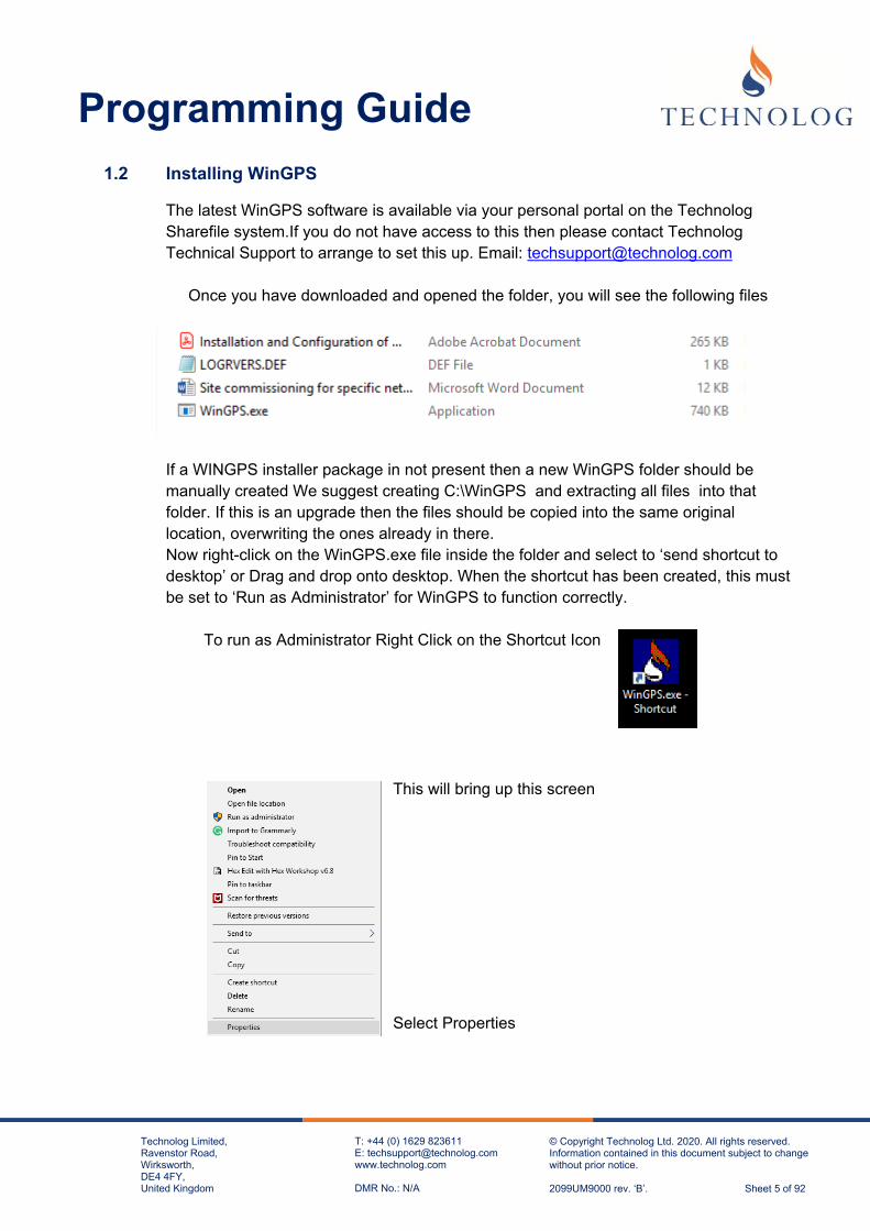
Once you have downloaded and opened the folder, you will see the following files
If a WINGPS installer package in not present then a new WinGPS folder should be manually created We suggest creating C:\WinGPS and extracting all files into that folder. If this is an upgrade then the files should be copied into the same original location, overwriting the ones already in there. Now right-click on the WinGPS.exe file inside the folder and select to ‘send shortcut to desktop’ or Drag and drop onto desktop. When the shortcut has been created, this must be set to ‘Run as Administrator’ for WinGPS to function correctly.
To run as Administrator Right Click on the Shortcut Icon
This will bring up this screen Select Properties

Programming Guide
Technolog Limited, Ravenstor Road, Wirksworth, DE4 4FY, United Kingdom
T: +44 (0) 1629 823611 E: [email protected] www.technolog.com DMR No.: N/A
© Copyright Technolog Ltd. 2020. All rights reserved. Information contained in this document subject to change without prior notice. 2099UM9000 rev. ‘B’. Sheet 6 of 92
This will bring up this screen Click on Change Settings for all users This will bring up this screen
Select run this program as an administrator and click on Apply and OK and OK again on the next screen

Programming Guide
Technolog Limited, Ravenstor Road, Wirksworth, DE4 4FY, United Kingdom
T: +44 (0) 1629 823611 E: [email protected] www.technolog.com DMR No.: N/A
© Copyright Technolog Ltd. 2020. All rights reserved. Information contained in this document subject to change without prior notice. 2099UM9000 rev. ‘B’. Sheet 7 of 92
When running WinGPS for the first time, a red banner will be displayed until the correct Comms Port is selected as per the image below. Before setting this up, go to the next section,
1.3 Installation of Local Communications Cable
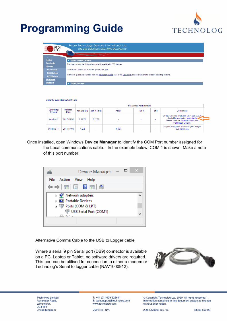
The next stage is to install the appropriate local communications cable. There are typically two types of local communications cables supplied by Technolog for use with Cello 4s, as identified below. USB to Logger Cable – (item NAV1000081) – Driver installation required. Connect directly to any available USB socket on a Windows Laptop/PC. A driver must be loaded prior to inserting the cable. The latest installation driver is available from the manufacturer’s link below: http://www.ftdichip.com/Drivers/D2XX.htm
Programming Guide
Technolog Limited, Ravenstor Road, Wirksworth, DE4 4FY, United Kingdom
T: +44 (0) 1629 823611 E: [email protected] www.technolog.com DMR No.: N/A
© Copyright Technolog Ltd. 2020. All rights reserved. Information contained in this document subject to change without prior notice. 2099UM9000 rev. ‘B’. Sheet 8 of 92
Once installed, open Windows Device Manager to identify the COM Port number assigned for
the Local communications cable. In the example below, COM 1 is shown. Make a note of this port number:
Alternative Comms Cable to the USB to Logger cable
Where a serial 9 pin Serial port (DB9) connector is available
on a PC, Laptop or Tablet, no software drivers are required. This port can be utilised for connection to either a modem or Technolog’s Serial to logger cable (NAV1000912).

Programming Guide
Technolog Limited, Ravenstor Road, Wirksworth, DE4 4FY, United Kingdom
T: +44 (0) 1629 823611 E: [email protected] www.technolog.com DMR No.: N/A
© Copyright Technolog Ltd. 2020. All rights reserved. Information contained in this document subject to change without prior notice. 2099UM9000 rev. ‘B’. Sheet 9 of 92
1.4 Configuration of WinGPS Communications Port
The WinGPS port settings can be opened by two methods:
1. By clicking on the Red Banner at the base of the WinGPS window to open the Options screen.
OR
2. By selecting Tools Options…
The correct Comm Port may be selected though the drop-down menu option in the top-left corner of the screen below:
Once a Comm Port has been selected, ensure the Initial comms rate remains at 1200 baud. The rest of the options can remain as they are. Select OK to save these settings.

Programming Guide
Technolog Limited, Ravenstor Road, Wirksworth, DE4 4FY, United Kingdom
T: +44 (0) 1629 823611 E: [email protected] www.technolog.com DMR No.: N/A
© Copyright Technolog Ltd. 2020. All rights reserved. Information contained in this document subject to change without prior notice. 2099UM9000 rev. ‘B’. Sheet 10 of 92
Section 2
Remote Communication Options
The Cello 4s can be programmed to transmit data via SMS to a Host PC Modem or via a TCP IP / UDP connection.
Option 1: Sending of Data directly to a Local Instance of PMAC Plus via SMS (Refer to Section 2.1)
Option 2: Sending Data directly to a Local Instance of PMAC Plus via a TCP/IP/UDP Data Connection (Refer to Section 2.2)
Option 3: Sending Data directly to a Local Instance of PMAC Plus via a Data Connection
through a secure ‘Demilitarised Zone’ (DMZ). (Refer to Section 2.3)
Option 4: Sending Data directly to WaterCore (Refer to Section 2.4)

Programming Guide
Technolog Limited, Ravenstor Road, Wirksworth, DE4 4FY, United Kingdom
T: +44 (0) 1629 823611 E: [email protected] www.technolog.com DMR No.: N/A
© Copyright Technolog Ltd. 2020. All rights reserved. Information contained in this document subject to change without prior notice. 2099UM9000 rev. ‘B’. Sheet 11 of 92
2.1 Sending Data directly to a Local Instance of PMAC Plus via SMS
2.1.1 Configure PMAC Plus server security settings.
Prior to the installation of Technolog PMAC Plus software, ensure that all login privileges for the local PC are set to local administrator, with full administrative privileges. For Technolog software to work correctly, the Windows User Account Control Settings needs to be changed to ‘Never Notify’. This is accessible by typing UAC in the Windows search box. Move the slider to the bottom position, ‘Never Notify’ as per the image below:
NOTE: Your computer must be restarted for this change to be enabled.

Programming Guide
Technolog Limited, Ravenstor Road, Wirksworth, DE4 4FY, United Kingdom
T: +44 (0) 1629 823611 E: [email protected] www.technolog.com DMR No.: N/A
© Copyright Technolog Ltd. 2020. All rights reserved. Information contained in this document subject to change without prior notice. 2099UM9000 rev. ‘B’. Sheet 12 of 92
2.1.2 Install PMAC Plus on Local Server
The latest PMAC Plus software is available via your personal portal on the Technolog Sharefile system. If you do not have access to this then please contact Technolog Technical Support to arrange to set this up. Email: [email protected] PMAC Plus will only function correctly on Microsoft Windows 10 and higher, or Windows Server 2012 R2 and higher. Save this zip file to your computer: To install PMAC Plus, unzip the files from the downloaded PMACPlus.zip file. Right click on the ‘Setup.exe’ and right-click to ‘Run as Administrator’
For a new installation, the following screens will appear:
Select Next>

Programming Guide
Technolog Limited, Ravenstor Road, Wirksworth, DE4 4FY, United Kingdom
T: +44 (0) 1629 823611 E: [email protected] www.technolog.com DMR No.: N/A
© Copyright Technolog Ltd. 2020. All rights reserved. Information contained in this document subject to change without prior notice. 2099UM9000 rev. ‘B’. Sheet 13 of 92
Select All Protocols.
.
Next>
The installation process will continue until the process has finished. Note: If Re-installing/Upgrading your system, the screen below will be displayed:
Please restart the computer once the installation is complete:
Programming Guide
Technolog Limited, Ravenstor Road, Wirksworth, DE4 4FY, United Kingdom
T: +44 (0) 1629 823611 E: [email protected] www.technolog.com DMR No.: N/A
© Copyright Technolog Ltd. 2020. All rights reserved. Information contained in this document subject to change without prior notice. 2099UM9000 rev. ‘B’. Sheet 14 of 92
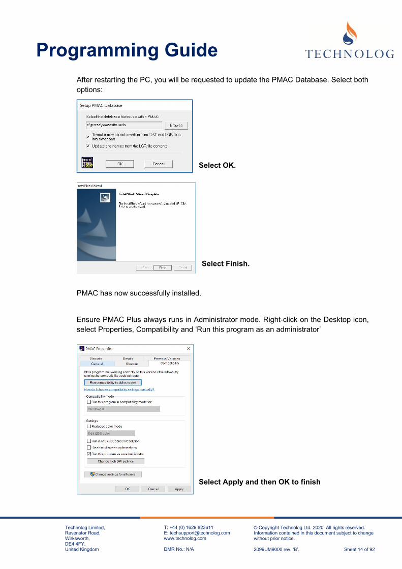
After restarting the PC, you will be requested to update the PMAC Database. Select both options:
Select OK. Select Finish.
PMAC has now successfully installed.
Ensure PMAC Plus always runs in Administrator mode. Right-click on the Desktop icon, select Properties, Compatibility and ‘Run this program as an administrator’
Select Apply and then OK to finish

Programming Guide
Technolog Limited, Ravenstor Road, Wirksworth, DE4 4FY, United Kingdom
T: +44 (0) 1629 823611 E: [email protected] www.technolog.com DMR No.: N/A
© Copyright Technolog Ltd. 2020. All rights reserved. Information contained in this document subject to change without prior notice. 2099UM9000 rev. ‘B’. Sheet 15 of 92
When PMAC starts, a pop-up window appears, prompting for a Licence request key. This should be supplied by the company where you have acquired the PMAC software, or you could contact Technolog UK. In the case of the latter, please send an email to [email protected] ensuring it contains a clear screen shot of the Licence Request Key, like this screen shot image to right. On receipt of the Activation code, enter your software licence key exactly as it reads, containing the spaces. Now select Update. Alternatively select ‘continue trial’ to temporarily remove the screen. During the trial period, the full features of PMAC are available, with the licence key screen appearing intermittently.
2.1.3 Configure PMAC permissions PMAC Plus requires various permissions in the registry to run in Windows.
Windows has two core variants, 32 bit and 64 bit. These variants have different registry structures:
32 Bit
HKEY_CURRENT_USER\Software\TechnologLtd\ HKEY_LOCAL_MACHINE\Software\TechnologLtd\ HKEY_LOCAL_MACHINE\Software\Technolog Ltd\ 64 Bit
HKEY_CURRENT_USER\Software\TechnologLtd\ HKEY_LOCAL_MACHINE\Software\Wow6432Node\TechnologLtd\ HKEY_LOCAL_MACHINE\Software\Wow6432Node\Technolog Ltd\ Note: PMAC requires full access to all these keys and the branches from each key.
Disk Access PMAC is usually installed to C:\PMAC and the application requires full access to this folder and all sub folders. If PMAC is installed to another folder, the same rules apply. Please contact your IT administrator or email [email protected] if you require any assistance with this procedure.

Programming Guide
Technolog Limited, Ravenstor Road, Wirksworth, DE4 4FY, United Kingdom
T: +44 (0) 1629 823611 E: [email protected] www.technolog.com DMR No.: N/A
© Copyright Technolog Ltd. 2020. All rights reserved. Information contained in this document subject to change without prior notice. 2099UM9000 rev. ‘B’. Sheet 16 of 92
2.1.4 Enable 2 way SMS communication with PMAC Plus
When an SMS Modem is installed on the PMAC Server, an operator can request information remotely to check the operation of PMAC Plus and receive alarms.
To use this Service, send an email to local distributor or [email protected], requesting the ‘Allow User SMS Interface facility’ and advise if your PMAC server has a 32 Bit or 64 Bit Windows Operating System. On receipt of the return email, place the file onto your desktop and run
2.1.5 Test the SIM Card intended for SMS HOST PC modem and remove the PIN Code Lock
Prior to inserting the SIM Card into any SMS PC Modem, it is important to check that the SIM card has the PIN Code disabled and has sufficient credit to perform 2-way SMS communications.
To ensure that the SIM card sends and receives SMS messages, simply insert into a Cellular phone and send a text message to and from the SIM card.
Refer to section 3.3 of this document for more instructions.
2.1.6 Identify and install the appropriate PC Modem for SMS communications
Option A – Installing Fastrack FXT009 (For 2G Networks / SIM Cards only)

Programming Guide
Technolog Limited, Ravenstor Road, Wirksworth, DE4 4FY, United Kingdom
T: +44 (0) 1629 823611 E: [email protected] www.technolog.com DMR No.: N/A
© Copyright Technolog Ltd. 2020. All rights reserved. Information contained in this document subject to change without prior notice. 2099UM9000 rev. ‘B’. Sheet 17 of 92
Kit comprises of: DB15M to DB9F Serial Cable Aerial (SMA) RS232 DB9 Male to DB15 Female cable If no RS232 DB9 Serial socket is available on the Server, it may be necessary to install a Prolific USB to RS232 adaptor cable (NAV1001944) where the drivers must be loaded prior to inserting the cable. Download the latest installation driver from the link below; http://www.ftdichip.com/Drivers/VCP.htm Ensuring the SIM Card is clean and free from fingerprints, install the SIM Card into the
modem, ensuring the SIM Card lock mechanism is closed by sliding over the locking
mechanism as shown in the images below:
Connect to an available RS232 DB9 Serial socket (or USB to RS232 Adaptor). Connect
Aerial to Modem, connect Power Supply Unit (PSU) to the Fastrack Modem and wait until
the LED starts to flash. A flashing led indicates that the SIM card has registered onto the
network.
Open PMAC Plus as SYSTEM MANAGER: User Name: system Password: system

Programming Guide
Technolog Limited, Ravenstor Road, Wirksworth, DE4 4FY, United Kingdom
T: +44 (0) 1629 823611 E: [email protected] www.technolog.com DMR No.: N/A
© Copyright Technolog Ltd. 2020. All rights reserved. Information contained in this document subject to change without prior notice. 2099UM9000 rev. ‘B’. Sheet 18 of 92
Select
Edit,
Communications Port
Cello Modems, Add..
Cello Modem
Next>
Select the Communications Port to which the Cello Modem is connected to. Communications Port (COM?) Next >
Select: Sierra Wireless / Wavecom FXT009 Next >
Programming Guide
Technolog Limited, Ravenstor Road, Wirksworth, DE4 4FY, United Kingdom
T: +44 (0) 1629 823611 E: [email protected] www.technolog.com DMR No.: N/A
© Copyright Technolog Ltd. 2020. All rights reserved. Information contained in this document subject to change without prior notice. 2099UM9000 rev. ‘B’. Sheet 19 of 92
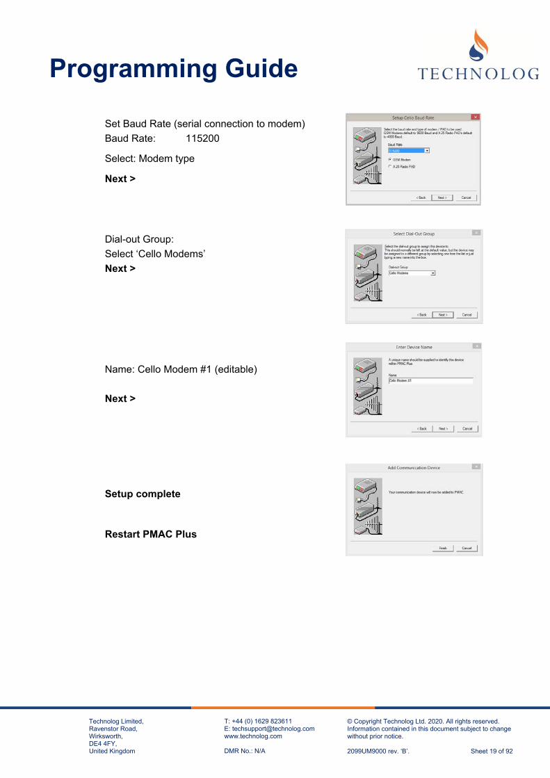
Set Baud Rate (serial connection to modem)
Baud Rate: 115200
Select: Modem type
Next >
Dial-out Group:
Select ‘Cello Modems’
Next >
Name: Cello Modem #1 (editable)
Next >
Setup complete
Restart PMAC Plus

Programming Guide
Technolog Limited, Ravenstor Road, Wirksworth, DE4 4FY, United Kingdom
T: +44 (0) 1629 823611 E: [email protected] www.technolog.com DMR No.: N/A
© Copyright Technolog Ltd. 2020. All rights reserved. Information contained in this document subject to change without prior notice. 2099UM9000 rev. ‘B’. Sheet 20 of 92
Option - B: Installation of Gemalto Modem (For 2G/3G SIM Cards)
Kit comprises of: EHSx Driver Installation USB-A to USB-B cable (see image) Aerial (SMA) Gemalto Modem
Locate the file EHSx Driver v1113.zip and unzip the contents.
If you do not have this file, email [email protected].
Extract the supplied EHSx Driver v1113 file to desktop. Open Windows Device Manager and connect the modem. You will see multiple entries in ‘Other devices’
Right-click on each item, individually, to Update Driver. Browse to desktop and to the EHSx Driver folder and select the USB sub-directory.

Programming Guide
Technolog Limited, Ravenstor Road, Wirksworth, DE4 4FY, United Kingdom
T: +44 (0) 1629 823611 E: [email protected] www.technolog.com DMR No.: N/A
© Copyright Technolog Ltd. 2020. All rights reserved. Information contained in this document subject to change without prior notice. 2099UM9000 rev. ‘B’. Sheet 21 of 92
You should see several entries for the Cinterion EHx USB in the Ports section but it is in the Modems parent option you need to check which details the port.
Find the correct COM port number by right-clicking on the device, Properties and select Modem. In this instance the modem is shown to be connected to COM3
Ensuring the SIM Card is clean and free from fingerprints, insert the SIM Card fully until you hear/feel the click of the locking mechanism. If you need to remove the SIM, depressing the SIM card will eject it from the modem. Connect USB-B plug to the Gemalto Modem and the USB-A plug to the PC. Connect the
Power Supply Unit (PSU) to the Gemalto Modem and attach the antenna. Wait until the
GREEN LED illuminates and the RED LED starts to flash.
Initial status Static Green LED After initialisation Static Green LED Flashing Red LED

Programming Guide
Technolog Limited, Ravenstor Road, Wirksworth, DE4 4FY, United Kingdom
T: +44 (0) 1629 823611 E: [email protected] www.technolog.com DMR No.: N/A
© Copyright Technolog Ltd. 2020. All rights reserved. Information contained in this document subject to change without prior notice. 2099UM9000 rev. ‘B’. Sheet 22 of 92
Open PMAC Plus in SYSTEM MANAGER:
Select Edit,
Communications Port
Cello Modems, Add..
Cello Modem
Next>
Select the Communications Port which the Host Modem is connected. Communications Port (COM?) Next > Select: Gemalto 3G Modem Next >
Set Baud Rate (serial connection to modem)
Baud Rate: 115200 Select; Modem type Next >

Programming Guide
Technolog Limited, Ravenstor Road, Wirksworth, DE4 4FY, United Kingdom
T: +44 (0) 1629 823611 E: [email protected] www.technolog.com DMR No.: N/A
© Copyright Technolog Ltd. 2020. All rights reserved. Information contained in this document subject to change without prior notice. 2099UM9000 rev. ‘B’. Sheet 23 of 92
Dial-out Group:
Select Cello Modems
Next >
Name: Cello Modem #1 (editable)
Next >
Finish >
Setup complete
Restart PMAC Plus

Programming Guide
Technolog Limited, Ravenstor Road, Wirksworth, DE4 4FY, United Kingdom
T: +44 (0) 1629 823611 E: [email protected] www.technolog.com DMR No.: N/A
© Copyright Technolog Ltd. 2020. All rights reserved. Information contained in this document subject to change without prior notice. 2099UM9000 rev. ‘B’. Sheet 24 of 92
2.1.7 Check the Host Modem (i.e. Option A or Option B) is visible in PMAC comms driver window
Open the Communications Device(s) and ‘click’ on this icon on the Windows toolbar.
The PMAC Communications window should open detailing all communication devices installed in PMAC. This screen also shows the PMAC version. You may need to provide this version number if requested by Tech Support.
If the Cello Modem has been installed correctly the modem will display “Searching for Cello Data” as per below:

Programming Guide
Technolog Limited, Ravenstor Road, Wirksworth, DE4 4FY, United Kingdom
T: +44 (0) 1629 823611 E: [email protected] www.technolog.com DMR No.: N/A
© Copyright Technolog Ltd. 2020. All rights reserved. Information contained in this document subject to change without prior notice. 2099UM9000 rev. ‘B’. Sheet 25 of 92
2.1.8 Confirm Operation of Host Modem
Send a text message in international format (i.e. +44..) containing only the letter S to the SIM Card in the Host Modem.
On receipt of this message, the Host Modem will reply with the status of PMAC.
The message on the phone should display ‘PMAC is running’.
However, if you do not receive a reply, please confirm the following:
PMAC Plus is running. The PC modem communications cable is plugged into the correct communication port
The modem is switched on (LED is illuminated and indicating modem registration)
The SIM card is correctly installed with the locking mechanism closed. The SIM PIN Code is disabled. The SIM ‘SMS’ number sent from the phone is correct.
Registry entries have been added (See Section 2.1.3 of this document).
However, if all the above have been checked, it may be necessary to validate the SIM again by placing the SIM inside a mobile phone and sending a SMS text message to another mobile / cellular phone.
Programming Guide
Technolog Limited, Ravenstor Road, Wirksworth, DE4 4FY, United Kingdom
T: +44 (0) 1629 823611 E: [email protected] www.technolog.com DMR No.: N/A
© Copyright Technolog Ltd. 2020. All rights reserved. Information contained in this document subject to change without prior notice. 2099UM9000 rev. ‘B’. Sheet 26 of 92
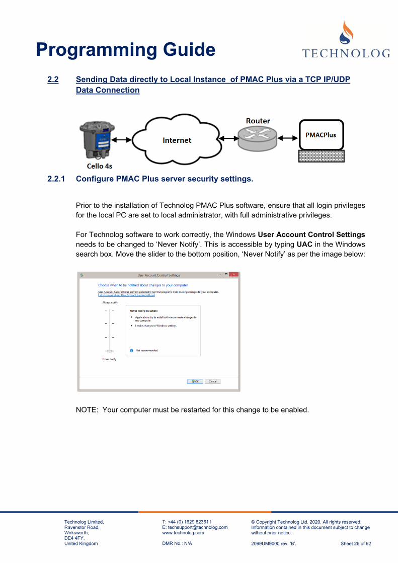
2.2 Sending Data directly to Local Instance of PMAC Plus via a TCP IP/UDP Data Connection
2.2.1 Configure PMAC Plus server security settings.
Prior to the installation of Technolog PMAC Plus software, ensure that all login privileges for the local PC are set to local administrator, with full administrative privileges. For Technolog software to work correctly, the Windows User Account Control Settings needs to be changed to ‘Never Notify’. This is accessible by typing UAC in the Windows search box. Move the slider to the bottom position, ‘Never Notify’ as per the image below:
NOTE: Your computer must be restarted for this change to be enabled.

Programming Guide
Technolog Limited, Ravenstor Road, Wirksworth, DE4 4FY, United Kingdom
T: +44 (0) 1629 823611 E: [email protected] www.technolog.com DMR No.: N/A
© Copyright Technolog Ltd. 2020. All rights reserved. Information contained in this document subject to change without prior notice. 2099UM9000 rev. ‘B’. Sheet 27 of 92
2.2.2 Install PMAC Plus on Local Server
The latest PMAC Plus software is available via your personal portal on the Technolog Sharefile system. If you do not have access to this then please contact Technolog Technical Support to arrange to set this up. Email: [email protected] PMAC Plus will only function correctly on Microsoft Windows 7 and higher, or Windows Server 2012 R2 and higher. Save this zip file to your computer: To install PMAC Plus, unzip the files from the downloaded PMACPlus.zip file. Right click on the ‘Setup.exe’ and right-click to ‘Run as Administrator’
For a new installation, the following screens will appear:
Select Next>

Programming Guide
Technolog Limited, Ravenstor Road, Wirksworth, DE4 4FY, United Kingdom
T: +44 (0) 1629 823611 E: [email protected] www.technolog.com DMR No.: N/A
© Copyright Technolog Ltd. 2020. All rights reserved. Information contained in this document subject to change without prior notice. 2099UM9000 rev. ‘B’. Sheet 28 of 92
Select All Protocols.
.
Next>
The installation process will continue until the process has finished. Note: If Re-installing/Upgrading your system, the screen below will be displayed:
Please restart the computer once the installation is complete:
Programming Guide
Technolog Limited, Ravenstor Road, Wirksworth, DE4 4FY, United Kingdom
T: +44 (0) 1629 823611 E: [email protected] www.technolog.com DMR No.: N/A
© Copyright Technolog Ltd. 2020. All rights reserved. Information contained in this document subject to change without prior notice. 2099UM9000 rev. ‘B’. Sheet 29 of 92
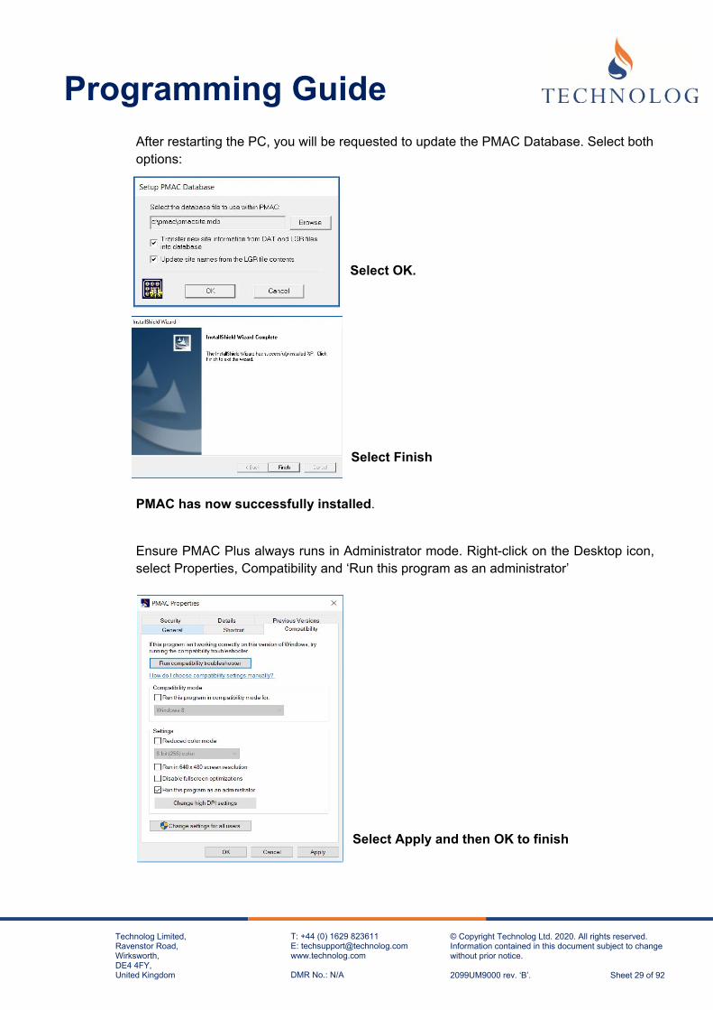
After restarting the PC, you will be requested to update the PMAC Database. Select both options:
Select OK.
Select Finish
PMAC has now successfully installed.
Ensure PMAC Plus always runs in Administrator mode. Right-click on the Desktop icon, select Properties, Compatibility and ‘Run this program as an administrator’
Select Apply and then OK to finish

Programming Guide
Technolog Limited, Ravenstor Road, Wirksworth, DE4 4FY, United Kingdom
T: +44 (0) 1629 823611 E: [email protected] www.technolog.com DMR No.: N/A
© Copyright Technolog Ltd. 2020. All rights reserved. Information contained in this document subject to change without prior notice. 2099UM9000 rev. ‘B’. Sheet 30 of 92
When PMAC starts, a pop-up window appears, prompting for a Licence request key. This should be supplied by the company where you have acquired the PMAC software, or you could contact Technolog UK. In the case of the latter, please send an email to [email protected] ensuring it contains a clear screen shot of the Licence Request Key, like this screen shot image to right. On receipt of the Activation code, enter your software licence key exactly as it reads, containing the spaces. Now select Update. Alternatively select ‘continue trial’ to temporarily remove the screen. During the trial period the full features of PMAC are available, with the licence key screen appearing intermittently.
2.2.3 Configure PMAC permissions PMAC Plus requires various permissions in the registry to run in Windows.
Windows has two core variants, 32 bit and 64 bit. These variants have different registry structures:
32 Bit
HKEY_CURRENT_USER\Software\TechnologLtd\ HKEY_LOCAL_MACHINE\Software\TechnologLtd\ HKEY_LOCAL_MACHINE\Software\Technolog Ltd\ 64 Bit
HKEY_CURRENT_USER\Software\TechnologLtd\ HKEY_LOCAL_MACHINE\Software\Wow6432Node\TechnologLtd\ HKEY_LOCAL_MACHINE\Software\Wow6432Node\Technolog Ltd\ Note: PMAC requires full access to all these keys and the branches from each key.
Disk Access PMAC is usually installed to C:\PMAC and the application requires full access to this folder and all sub folders. If PMAC is installed to another folder, the same rules apply. Please contact your IT administrator or email [email protected] if you require any assistance with this procedure.

Programming Guide
Technolog Limited, Ravenstor Road, Wirksworth, DE4 4FY, United Kingdom
T: +44 (0) 1629 823611 E: [email protected] www.technolog.com DMR No.: N/A
© Copyright Technolog Ltd. 2020. All rights reserved. Information contained in this document subject to change without prior notice. 2099UM9000 rev. ‘B’. Sheet 31 of 92
2.2.4 TGSN Installation Overview
To provide both security and communications with the Cello 4s, PMAC Plus uses a TGSN (Technolog GPRS Service Node) module.
This can be installed in between the ‘dirty’ internet and ‘clean’ corporate network as required.
The TGSN module may be either installed onto the same server as PMAC Plus (as described below) or onto a separate server (i.e. within what we call a DMZ). For security, we normally recommend the latter option, with the TGSN module situated away from the corporate network, residing between two firewalls creating a Demilitarised Zone (DMZ).
The TGSN module performs two key roles:
Receives and stores any inbound data / alarms sent by the Cello 4s for subsequent collection by PMAC Plus.
Allows outgoing messages from PMAC to be collected by the Cello 4s upon next inbound connection.
Any outgoing messages to the Cello data logger from PMAC Plus (i.e to fill data gaps) can be thought of as being stored in the TGSN 'outcache' for collection by the Cello. Oubound messages are picked-up when the Cello next communicates with the server installed with the TGSN module.
If the TGSN module is to be installed onto a separate server, away from PMAC, one firewall is normally configured to allow inbound traffic from the outside world, whilst the firewall separating the TGSN module from PMAC should be configured to allow outbound traffic, i.e. from PMAC to the TGSN module on a specific port. This method prevents any potential unauthorised 'inbound' connections through to the corporate network.

Programming Guide
Technolog Limited, Ravenstor Road, Wirksworth, DE4 4FY, United Kingdom
T: +44 (0) 1629 823611 E: [email protected] www.technolog.com DMR No.: N/A
© Copyright Technolog Ltd. 2020. All rights reserved. Information contained in this document subject to change without prior notice. 2099UM9000 rev. ‘B’. Sheet 32 of 92
As a minimum requirement you would need a static IP address / domain name for the Cello to send data to. Traffic arriving on this address may need to be port -forwarded to the PMAC server inside the corporate network.
For data communications;
Cello's should be configured for GPRS/3G/NB-IoT data - requiring a specific configuration file.
The Cello SIM telephone number should be saved into the 4s Network APN, user name and password would need to programmed into the Cello 4s

Programming Guide
Technolog Limited, Ravenstor Road, Wirksworth, DE4 4FY, United Kingdom
T: +44 (0) 1629 823611 E: [email protected] www.technolog.com DMR No.: N/A
© Copyright Technolog Ltd. 2020. All rights reserved. Information contained in this document subject to change without prior notice. 2099UM9000 rev. ‘B’. Sheet 33 of 92
2.2.5 Installing TGSN Communication Module onto PMAC Local Server
The latest TGSN software module is available via your personal portal on the Technolog Sharefile system. If you do not have access to this then please contact Technolog Technical Support to arrange to set this up. Email: [email protected]
1. Ensure that the computer is logged in under Administrator mode.
2. Create a folder called TGSN, ideally on your local computer’s C: drive (C:\TGSN), then extract the TGSN.exe & the TGSN_PMAC-Setup (32 or 64).reg files into that folder.
3. Ensure all Users have full permissions for this TGSN folder. Right-click on the folder and select Properties. Click Edit and grant full permissions for each group or user name listed in the window, Clicking on Apply OK to take you back to the TGSN Properties menu.
4. Select ‘Advanced…
5. Identify if the computer is running Windows 32 or 64-bit and within the TGSN folder, rename the correct file (either TGSN-PMAC-Setup (32).re1 or TGSN-PMAC-Setup (64).re1) from .re1 to .reg For example a 64-bit Windows computer you would need to rename the file to: TGSN-PMAC-Setup (64).reg

Programming Guide
Technolog Limited, Ravenstor Road, Wirksworth, DE4 4FY, United Kingdom
T: +44 (0) 1629 823611 E: [email protected] www.technolog.com DMR No.: N/A
© Copyright Technolog Ltd. 2020. All rights reserved. Information contained in this document subject to change without prior notice. 2099UM9000 rev. ‘B’. Sheet 34 of 92
6. Now double-click on this to run the file. This will copy the TGSN information to Windows
registry:
Select Yes
Still within the TGSN folder, rename the TGSN.ex_ file to TGSN.exe (confirm the change).Right-click on this file and choose Properties, Compatibility, ‘Change settings for all users’ and select the ‘Run this program as administrator; option. Now select OK, and OK again to come out of Properties.

Programming Guide
Technolog Limited, Ravenstor Road, Wirksworth, DE4 4FY, United Kingdom
T: +44 (0) 1629 823611 E: [email protected] www.technolog.com DMR No.: N/A
© Copyright Technolog Ltd. 2020. All rights reserved. Information contained in this document subject to change without prior notice. 2099UM9000 rev. ‘B’. Sheet 35 of 92
7. Through Windows, you now need to open up the DOS Command Prompt. Search for ‘Command’ or ‘CMD’, highlight the program, and then right –click on Run as Administrator:
8. Inside the Command Prompt window, type in cd \tgsn to change to the TGSN folder (presuming the folder has been created in the recommended location of C:\TGSN). Your prompt should now be C:\TGSN>
9. Type in tgsn /install and press return. There is no confirmation this has worked, the prompt will just return to C:\TGSN>
10. Now restart the computer.
11. Once restarted, browse to TGSN folder. There should now be a new folder in there called Logs. Open this folder and there will be a text file. This is a TGSN debug file, and will be named something like (date) _PMACDbg.txt
12. Open this text file using Windows Notepad and it will display a TGSN key request number, as per the screen below:

Programming Guide
Technolog Limited, Ravenstor Road, Wirksworth, DE4 4FY, United Kingdom
T: +44 (0) 1629 823611 E: [email protected] www.technolog.com DMR No.: N/A
© Copyright Technolog Ltd. 2020. All rights reserved. Information contained in this document subject to change without prior notice. 2099UM9000 rev. ‘B’. Sheet 36 of 92
13. Copy this number in an email to Technolog Tech Support: [email protected] (or your Technolog Sales Representative) and an unlock code registry file will be supplied by return email. Please state if this is for a 32 or 64-bit computer when you request the unlock key.
14. Rename the unlock code file from .re_ to .reg upon receipt and run this. Select Yes to copy this to registry, and then OK to exit.
15. Now restart the computer again.
16. Check that the TGSN service has been installed correctly by typing in Services in Windows search and then looking for the TGSN entry. The TGSN service should be running:
17. If the service is listed and running then skip to part 18. If it is not listed or not running then continue below.
18. Check the security permissions for the TGSN folder as per Step 2. above, and also ensure that users have full permissions for both Technolog entries in Windows registry. If PMAC is installed locally then this should have been set up at the time PMAC Plus was installed. If not then see below 32 bit HKEY_CURRENT_USER\Software\TechnologLtd\ HKEY_LOCAL_MACHINE\Software\TechnologLtd\ HKEY_LOCAL_MACHINE\Software\Technolog Ltd\ 64 bit HKEY_CURRENT_USER\Software\TechnologLtd entries \ HKEY_LOCAL_MACHINE\Software\Wow6432Node\TechnologLtd\ HKEY_LOCAL_MACHINE\Software\Wow6432Node\Technolog Ltd\ PMAC and TGSN require full access to all these keys and the sub branches from each key.

Programming Guide
Technolog Limited, Ravenstor Road, Wirksworth, DE4 4FY, United Kingdom
T: +44 (0) 1629 823611 E: [email protected] www.technolog.com DMR No.: N/A
© Copyright Technolog Ltd. 2020. All rights reserved. Information contained in this document subject to change without prior notice. 2099UM9000 rev. ‘B’. Sheet 37 of 92
19. Configure PMAC Communications
Run PMAC Plus and Log in as System Manager Edit, Communication Ports. Select ‘Utility Data Networks’ and select ‘Add’
20. Select Utility Data Network (TMSC/TGSN)
Next >
21. Click on the pulldown to select;
Local GPRS Service
Select Next >
22. Leave the Account Name & Password as;
Account Name / System ID: PMAC Password: PMAC
23. Select the default Dial-out group:
Utility Network

Programming Guide
Technolog Limited, Ravenstor Road, Wirksworth, DE4 4FY, United Kingdom
T: +44 (0) 1629 823611 E: [email protected] www.technolog.com DMR No.: N/A
© Copyright Technolog Ltd. 2020. All rights reserved. Information contained in this document subject to change without prior notice. 2099UM9000 rev. ‘B’. Sheet 38 of 92
24. Keep the default selection
Select Next >
25. Select Finish >
2.2.6 Check that the TGSN connection is visible in PMAC comms driver window
Open the Communications Device(s) and ‘click’ on this icon on the PC toolbar
The PMAC Communications window should open detailing all communication devices installed in PMAC. The TGSN entries should say “Waiting for Messages” as per below:

Programming Guide
Technolog Limited, Ravenstor Road, Wirksworth, DE4 4FY, United Kingdom
T: +44 (0) 1629 823611 E: [email protected] www.technolog.com DMR No.: N/A
© Copyright Technolog Ltd. 2020. All rights reserved. Information contained in this document subject to change without prior notice. 2099UM9000 rev. ‘B’. Sheet 39 of 92
2.2.7 Check Cello TCP – IP Inbound Connection
The externalIP address / domain name and port number is typically programmed directly into the Cello. The router (if fitted) should forward incoming traffic arriving on port 1801 to the TGSN Module. This connection should be tested prior to setting up the Cello. A typical online site to check this is detailed below:
https://yougetsignal.com/tools/open-ports/
This tool checks that any TCP-IP / UDP data connections to that external IP address are correctly port forwarded to the TGSN server.
Please ensure your port forwarding of data from the router to the TGSN module is configured correctly and the TGSN application is not being blocked by any firewalls.
External IP Address of the Router Typical Port Number used by the TGSN Module .

Programming Guide
Technolog Limited, Ravenstor Road, Wirksworth, DE4 4FY, United Kingdom
T: +44 (0) 1629 823611 E: [email protected] www.technolog.com DMR No.: N/A
© Copyright Technolog Ltd. 2020. All rights reserved. Information contained in this document subject to change without prior notice. 2099UM9000 rev. ‘B’. Sheet 40 of 92
2.3 Sending Data directly to Local Instance of PMAC Plus via a Data Connection through a Demilitarised Zone (DMZ)
2.3.1 Configure PMAC Plus AND TGSN server security settings.
Prior to the installation of Technolog PMAC Plus and TGSN software, ensure that all login privileges for the local PC are set to local administrator, with full administrative privileges. For Technolog software to work correctly, the Windows User Account Control Settings needs to be changed to ‘Never Notify’. This is accessible by typing UAC in the Windows search box. Move the slider to the bottom position, ‘Never Notify’ as per the image below:
NOTE: Your computer must be restarted for this change to be enabled.

Programming Guide
Technolog Limited, Ravenstor Road, Wirksworth, DE4 4FY, United Kingdom
T: +44 (0) 1629 823611 E: [email protected] www.technolog.com DMR No.: N/A
© Copyright Technolog Ltd. 2020. All rights reserved. Information contained in this document subject to change without prior notice. 2099UM9000 rev. ‘B’. Sheet 41 of 92
2.3.2 Install PMAC Plus on Local Server (Outside of DMZ)
The latest PMAC Plus software is available via your personal portal on the Technolog Sharefile system. If you do not have access to this then please contact Technolog Technical Support to arrange to set this up. Email: [email protected] PMAC Plus will only function correctly on Microsoft Windows 7 and higher, or Windows Server 2012 R2 and higher. Save this zip file to your computer: To install PMAC Plus, unzip the files from the downloaded PMACPlus.zip file. Right click on the ‘Setup.exe’ and right-click to ‘Run as Administrator’
For a new installation, the following screens will appear:
Select Next>

Programming Guide
Technolog Limited, Ravenstor Road, Wirksworth, DE4 4FY, United Kingdom
T: +44 (0) 1629 823611 E: [email protected] www.technolog.com DMR No.: N/A
© Copyright Technolog Ltd. 2020. All rights reserved. Information contained in this document subject to change without prior notice. 2099UM9000 rev. ‘B’. Sheet 42 of 92
Select All Protocols.
Next>
The installation process will continue until the process has finished. Note: If Re-installing/Upgrading your system, the screen below will be displayed:
Please restart the computer once the installation is complete:

Programming Guide
Technolog Limited, Ravenstor Road, Wirksworth, DE4 4FY, United Kingdom
T: +44 (0) 1629 823611 E: [email protected] www.technolog.com DMR No.: N/A
© Copyright Technolog Ltd. 2020. All rights reserved. Information contained in this document subject to change without prior notice. 2099UM9000 rev. ‘B’. Sheet 43 of 92
After restarting the PC, you will be requested to update the PMAC Database. Select both options:
Select OK.
PMAC has now successfully installed.
Select Finish
Ensure PMAC Plus always runs in Administrator mode. Right-click on the Desktop icon, select Properties, Compatibility and ‘Run this program as an administrator’
Select Apply and then OK to finish

Programming Guide
Technolog Limited, Ravenstor Road, Wirksworth, DE4 4FY, United Kingdom
T: +44 (0) 1629 823611 E: [email protected] www.technolog.com DMR No.: N/A
© Copyright Technolog Ltd. 2020. All rights reserved. Information contained in this document subject to change without prior notice. 2099UM9000 rev. ‘B’. Sheet 44 of 92
When PMAC starts, a pop-up window appears, prompting for a Licence request key. This should be supplied by the company where you acquired the PMAC software, or you could contact Technolog UK In the case of the latter, please send an email to [email protected] ensuring it contains a clear screen shot of the Key code and the code number, complete with spaces. On receipt of the Activation code, enter your software licence key exactly as it reads, containing the spaces. Now select Update. Alternatively select ‘continue trial’ to temporarily remove the screen. During the trial period the full features of PMAC are available, with the licence key screen appearing intermittently.
2.3.3 Configure PMAC permissions PMAC Plus requires various permissions in the registry to run in Windows.
Windows has two core variants, 32 bit and 64 bit. These variants have different registry structures:
32 Bit
HKEY_CURRENT_USER\Software\TechnologLtd\ HKEY_LOCAL_MACHINE\Software\TechnologLtd\ HKEY_LOCAL_MACHINE\Software\Technolog Ltd\ 64 Bit
HKEY_CURRENT_USER\Software\TechnologLtd\ HKEY_LOCAL_MACHINE\Software\Wow6432Node\TechnologLtd\ HKEY_LOCAL_MACHINE\Software\Wow6432Node\Technolog Ltd\ Note: PMAC requires full access to all these keys and the branches from each key.
Disk Access PMAC is usually installed to C:\PMAC and the application requires full access to this folder and all sub folders. If PMAC is installed to another folder, the same rules apply. Please contact your IT administrator or email [email protected] if you require any assistance with this procedure.

Programming Guide
Technolog Limited, Ravenstor Road, Wirksworth, DE4 4FY, United Kingdom
T: +44 (0) 1629 823611 E: [email protected] www.technolog.com DMR No.: N/A
© Copyright Technolog Ltd. 2020. All rights reserved. Information contained in this document subject to change without prior notice. 2099UM9000 rev. ‘B’. Sheet 45 of 92
2.3.4 TGSN Installation Overview
To provide both security and communications with the Cello 4s, PMAC Plus uses a TGSN module. This can be installed in between the ‘dirty’ internet and ‘clean’ corporate network as required. The TGSN module may be either installed onto the same server as PMAC Plus or onto a separate server (as described below) i.e. within what we call a DMZ. For security, we normally recommend the latter option, with the TGSN module situated away from the corporate network, residing between two firewalls creating a Demilitarised Zone (DMZ).
The TGSN module performs two key roles:
Receives and stores any inbound data / alarms sent by the Cello 4s for subsequent collection by PMAC Plus
Allows outgoing messages from PMAC to be collected by the Cello 4s upon next inbound connection.
Any outgoing messages to the Cello data logger from PMAC Plus (i.e to fill data gaps) can be thought of as being stored in the TGSN 'outcache' for collection by the Cello. Oubound messages are picked-up when the Cello next communicates with the server installed with the TGSN module.
If the TGSN module is to be installed onto a separate server, away from PMAC, one firewall is normally be configured to allow inbound traffic from the outside world, whilst the firewall separating the TGSN module from PMAC should be configured to allow outbound traffic, i.e. from PMAC to the TGSN module on a specific port. This method prevents any potential unauthorised 'inbound' connections through to the corporate network.
As a minimum requirement, a static IP address / domain name for the Cello to send data to is required. Traffic arriving on this address may need to be port -forwarded to the PMAC server inside the corporate network. The Cello should be configured for GPRS/3G data using a specific configuration file.

Programming Guide
Technolog Limited, Ravenstor Road, Wirksworth, DE4 4FY, United Kingdom
T: +44 (0) 1629 823611 E: [email protected] www.technolog.com DMR No.: N/A
© Copyright Technolog Ltd. 2020. All rights reserved. Information contained in this document subject to change without prior notice. 2099UM9000 rev. ‘B’. Sheet 46 of 92
2.3.5 Installing TGSN Communication Module inside DMZ
The latest TGSN software module is available via your personal portal on the Technolog Sharefile system. If you do not have access to this then please contact Technolog Technical Support to arrange to set this up. Email: [email protected]
1. Create a folder called TGSN, ideally on your local computer’s C: drive (C:\TGSN), then extract the contents of the downloaded TGSN.zip to that folder.
2. Ensure all Users are allowed full permissions for this TGSN folder. Right-click on the folder and select Properties, Security and select the Users group at the bottom of the list. Click Edit and allow Full control before clicking on Apply and OK:
3. Identify if the computer is running Windows 32 or 64-bit and within the TGSN folder, rename the correct file (either TGSN-PMAC-Setup (32).re1 or TGSN-PMAC-Setup (64).re1) from .re1 to .reg For example a 64-bit Windows computer you would need to rename the file to: TGSN-PMAC-Setup (64).reg
4. Now double-click on this to run the file. This will copy the TGSN information to Windows registry:
Select Yes

Programming Guide
Technolog Limited, Ravenstor Road, Wirksworth, DE4 4FY, United Kingdom
T: +44 (0) 1629 823611 E: [email protected] www.technolog.com DMR No.: N/A
© Copyright Technolog Ltd. 2020. All rights reserved. Information contained in this document subject to change without prior notice. 2099UM9000 rev. ‘B’. Sheet 47 of 92
5. Still within the TGSN folder, rename the TGSN.ex_ file to TGSN.exe (confirm the change), before right-clicking on this and choosing Properties, Compatibility, ‘Change settings for all users’ and select the ‘Run this program as administrator; option. Now select OK, and OK again to come out of Properties.
6. Through Windows, you now need to open up Command Prompt. Search for ‘Command’ or ‘CMD’ and then right –click on the program to run as Administrator:
7. Inside the Command Prompt window, type in cd \tgsn to change to the TGSN folder (presuming the folder has been created in the recommended location of C:\TGSN). Your

Programming Guide
Technolog Limited, Ravenstor Road, Wirksworth, DE4 4FY, United Kingdom
T: +44 (0) 1629 823611 E: [email protected] www.technolog.com DMR No.: N/A
© Copyright Technolog Ltd. 2020. All rights reserved. Information contained in this document subject to change without prior notice. 2099UM9000 rev. ‘B’. Sheet 48 of 92
prompt should now be C:\TGSN>
8. Type in tgsn /install and press return. There is no confirmation this has worked, the prompt will just return to C:\TGSN>
9. Now restart the computer.
10. Once restarted, browse to TGSN folder. There should now be a new folder in there called Logs. Open this folder and there will be a text file. This is a TGSN debug file, and will be named something like (date) _PMACDbg.txt
11. Open this text file using Windows Notepad and it will display a TGSN key request number, as per the screen below:
12. Copy this number in an email to Technolog Tech Support: [email protected] (or your Technolog area representative) and an unlock code registry file will be supplied by return email. Please state if this is for a 32 or 64-bit computer when you request the unlock key.
13. Rename the unlock code file from .re_ to .reg upon receipt and run this. Select Yes to copy this to registry, and then OK to exit.
14. Now restart the computer again.
15. Check that the TGSN service has been installed correctly by typing in Services in Windows search and then looking for the TGSN entry. The TGSN service should be Running:

Programming Guide
Technolog Limited, Ravenstor Road, Wirksworth, DE4 4FY, United Kingdom
T: +44 (0) 1629 823611 E: [email protected] www.technolog.com DMR No.: N/A
© Copyright Technolog Ltd. 2020. All rights reserved. Information contained in this document subject to change without prior notice. 2099UM9000 rev. ‘B’. Sheet 49 of 92
16. If the service is listed and running then skip to 18. If it is not listed or not running then continue below.
17. Check the security permissions for the TGSN folder as per Step 2. above, and also ensure that users have full permissions for both Technolog entries in Windows registry. If PMAC is installed locally then this should have been set up at the time PMAC Plus was installed. If not then see below for the entries: 32 bit HKEY_CURRENT_USER\Software\TechnologLtd\ HKEY_LOCAL_MACHINE\Software\TechnologLtd\ HKEY_LOCAL_MACHINE\Software\Technolog Ltd\ 64 bit HKEY_CURRENT_USER\Software\TechnologLtd\ HKEY_LOCAL_MACHINE\Software\Wow6432Node\TechnologLtd\ HKEY_LOCAL_MACHINE\Software\Wow6432Node\Technolog Ltd\ PMAC and TGSN require full access to all these keys and the sub branches from each key.
18. Configure PMAC Communications
Run PMAC Plus and Log in as System Manager Edit, Communication Ports. Select ‘Utility Data Networks’ and select ‘Add’

Programming Guide
Technolog Limited, Ravenstor Road, Wirksworth, DE4 4FY, United Kingdom
T: +44 (0) 1629 823611 E: [email protected] www.technolog.com DMR No.: N/A
© Copyright Technolog Ltd. 2020. All rights reserved. Information contained in this document subject to change without prior notice. 2099UM9000 rev. ‘B’. Sheet 50 of 92
19. Select Utility Data Network (TMSC/TGSN)
Next >
20. From the pull down menu select Manual
Enter the IP address or machine name of where the TGSN module is installed Enter the Server Port number (8100 by default)
Select Next >
21. Leave the Account Name & Password as;
Account Name / System ID: PMAC Password: PMAC
22. Select the default Dial-out group:
Utility Network

Programming Guide
Technolog Limited, Ravenstor Road, Wirksworth, DE4 4FY, United Kingdom
T: +44 (0) 1629 823611 E: [email protected] www.technolog.com DMR No.: N/A
© Copyright Technolog Ltd. 2020. All rights reserved. Information contained in this document subject to change without prior notice. 2099UM9000 rev. ‘B’. Sheet 51 of 92
23. Enter the name for the TGSN server
Select Next >
24. Select Finish >
Restart PMAC
2.3.6 Check that the TGSN connection is visible in PMAC comms driver window
Open the Communications Device(s) and ‘click’ on this icon on the PC toolbar
The PMAC Communications window should open detailing all communication devices installed in PMAC. The TGSN entries should say “Waiting for Messages”.

Programming Guide
Technolog Limited, Ravenstor Road, Wirksworth, DE4 4FY, United Kingdom
T: +44 (0) 1629 823611 E: [email protected] www.technolog.com DMR No.: N/A
© Copyright Technolog Ltd. 2020. All rights reserved. Information contained in this document subject to change without prior notice. 2099UM9000 rev. ‘B’. Sheet 52 of 92
The external IP address / domain name and port number is typically programmed directly into the Cello. The router (if fitted) should forwards incoming traffic arriving on port 1801 to the TGSN Module. This connection should be tested prior to setting up the Cello. A typical online site to check this is detailed below:
https://yougetsignal.com/tools/open-ports/
This tool checks that any TCP-IP / UDP data connections to that external IP address are correctly port forwarded to the TGSN server. Please ensure your port forwarding of data from the router to the TGSN module is configured correctly and the TGSN application is not being blocked by any firewalls.
External IP Address of the Router Typical port Number used by the TGSN Module

Programming Guide
Technolog Limited, Ravenstor Road, Wirksworth, DE4 4FY, United Kingdom
T: +44 (0) 1629 823611 E: [email protected] www.technolog.com DMR No.: N/A
© Copyright Technolog Ltd. 2020. All rights reserved. Information contained in this document subject to change without prior notice. 2099UM9000 rev. ‘B’. Sheet 53 of 92
2.4 Sending Data directly to Utilicore Webserver
Please contact your area sales representative or email Technolog Tech Support: [email protected].
We will require the following information:
Your full contact details Email address Serial number of each Cello 4S SIM telephone number (if SIM is not provided by Technolog) Details of any purchase order / contract Details of an existing Utilicore account, including the Utilicore website address if
already subscribed. Typically, an email address is used as a username.

Programming Guide
Technolog Limited, Ravenstor Road, Wirksworth, DE4 4FY, United Kingdom
T: +44 (0) 1629 823611 E: [email protected] www.technolog.com DMR No.: N/A
© Copyright Technolog Ltd. 2020. All rights reserved. Information contained in this document subject to change without prior notice. 2099UM9000 rev. ‘B’. Sheet 54 of 92
Section 3
Cello 4s SIM Card Selection and Testing
3.1 Select SIM card for use inside Cello 4S
The Cello 4s can be used with 2G & 3G capable SIM Cards for both 2G (SMS/GPRS), 3G, or Cellular IoT Networks (model dependant). Technolog recommends using SIM cards with sufficient credit for either SMS or Data transmission based on the intended network type / frequency of transmission.
3.2 Test the SIM Card intended for use inside Cello modem in a mobile phone
Prior to inserting the SIM Card into any Cello Modem, it is important to check that the SIM card can register and any PIN code is disabled
If SMS communications is being used, you should ensure that the SIM card can send and receives SMS messages. Simply insert into a Cellular phone and attempt to send a text message to and from the SIM card.
3.3 Insert the SIM into the Cello 4s
Remove the Cello 4s lid, insert the SIM Card in accordance with the Cello 4s Product Manual (2099PM9000)
Refer to; “Entering the enclosure” and “SIM Card replacement”
When inserted the SIM Card into the holder, the SIM Card becomes locked in place via a sprung latch mechanism.
If you need to remove the SIM card, it is only possible by withdrawing the latch away from the SIM card allowing the SIM card to be partially ejected. If removed, ensure the SIM card contacts are kept clean and free from fingerprints, before refitting.

Programming Guide
Technolog Limited, Ravenstor Road, Wirksworth, DE4 4FY, United Kingdom
T: +44 (0) 1629 823611 E: [email protected] www.technolog.com DMR No.: N/A
© Copyright Technolog Ltd. 2020. All rights reserved. Information contained in this document subject to change without prior notice. 2099UM9000 rev. ‘B’. Sheet 55 of 92
3.4 Cellular Signal Testing
Perform a signal / SIM test using WinGPS. Select ‘Modem’ ‘Wake GSM Modem Shift+F1’ to Wake GSM Modem.
This procedure must be done to validate coverage for the SIM Card Network Service provider and that the Cello 4s can read the SIM Card IMSI
Base station information shows the dBm level as an indication of signal strength.
Note: To avoid excessive battery consumption this mode should not be enabled for more than 3 minutes.

Programming Guide
Technolog Limited, Ravenstor Road, Wirksworth, DE4 4FY, United Kingdom
T: +44 (0) 1629 823611 E: [email protected] www.technolog.com DMR No.: N/A
© Copyright Technolog Ltd. 2020. All rights reserved. Information contained in this document subject to change without prior notice. 2099UM9000 rev. ‘B’. Sheet 56 of 92
3.5. Typical Rx Levels:
Typical Rx Levels: <100 dBm Poor signal strength Intermittent communications are likely. Repositioning of Cello or use of external antenna advised. Consider alternative network service providers and / or different modes of communication -86 to -99 dBm Fair signal strength > -85 dBm Good to excellent signal strength Reliable transmission expected Network registration issues unlikely
3.6 Forcing registration onto specific network access / technology –
OPTIONAL
Selecting a preference can help reduce network registration time or registration difficulty. Note:
A Cello 4s supplied with a 2G QB (SMS, TCP-IP and UDP) modem, the internal antenna supports the following Bandwidths. 800 / 850 / 1800 / 1900 MHz. A Cello 4s supplied with a 3G_GL 2G and 3G (SMS, TCP-IP and UDP) modem, the internal antenna supports: 800 / 850 / 1800 / 1900 MHz. If selecting a SIM Card supporting 3G ‘2100MHz’ frequency, you must ensure that an external antenna supporting 2100Mhz is attached to the external aerial port .

Programming Guide
Technolog Limited, Ravenstor Road, Wirksworth, DE4 4FY, United Kingdom
T: +44 (0) 1629 823611 E: [email protected] www.technolog.com DMR No.: N/A
© Copyright Technolog Ltd. 2020. All rights reserved. Information contained in this document subject to change without prior notice. 2099UM9000 rev. ‘B’. Sheet 57 of 92
To set a preferred network / access technology, open the Terminal screen and perform a signal Strength test.
Once the modem has responded, press the <ENTER> key to stop the sequence like below.

Programming Guide
Technolog Limited, Ravenstor Road, Wirksworth, DE4 4FY, United Kingdom
T: +44 (0) 1629 823611 E: [email protected] www.technolog.com DMR No.: N/A
© Copyright Technolog Ltd. 2020. All rights reserved. Information contained in this document subject to change without prior notice. 2099UM9000 rev. ‘B’. Sheet 58 of 92
Now select Modem tab, then navigate down to Access Technologies and Bands
Preferred networks of 2G or 3G bands can be individually selected. In the example below both 2G + 3G are selected:
Perform the Signal test again, ensuring all selected Bands are available. If selecting a SIM Card supporting 3G ‘2100MHz’ frequency, you must ensure that an external antenna supporting 2100Mhz is attached to the external aerial port
To avoid excessive battery consumption, do not perform this test for more than 3 minutes.
Refit the lid, ensuring no debris around the top of the Cello 4s body and the rubber seal of the Cello 4s lid assembly. It is advisable to repeat the signal test to ensure the aerial connection has not become dislodged, after refitting the aerial/lid assembly.

Programming Guide
Technolog Limited, Ravenstor Road, Wirksworth, DE4 4FY, United Kingdom
T: +44 (0) 1629 823611 E: [email protected] www.technolog.com DMR No.: N/A
© Copyright Technolog Ltd. 2020. All rights reserved. Information contained in this document subject to change without prior notice. 2099UM9000 rev. ‘B’. Sheet 59 of 92
When you have completed the signal test, press the <ENTER> key to stop the Cello Signal test Type +++ then <ENTER> and this will force the mode to shut down like the below screen shot. It is now safe to close the terminal window down close the Terminal window, click on the ‘X’ at the TOP/RIGHT corner of the Terminal screen.

Programming Guide
Technolog Limited, Ravenstor Road, Wirksworth, DE4 4FY, United Kingdom
T: +44 (0) 1629 823611 E: [email protected] www.technolog.com DMR No.: N/A
© Copyright Technolog Ltd. 2020. All rights reserved. Information contained in this document subject to change without prior notice. 2099UM9000 rev. ‘B’. Sheet 60 of 92
WinGPS Terminal can now be closed.

Programming Guide
Technolog Limited, Ravenstor Road, Wirksworth, DE4 4FY, United Kingdom
T: +44 (0) 1629 823611 E: [email protected] www.technolog.com DMR No.: N/A
© Copyright Technolog Ltd. 2020. All rights reserved. Information contained in this document subject to change without prior notice. 2099UM9000 rev. ‘B’. Sheet 61 of 92
Section 4
Cello 4s Programming
4.1 Connect communications cable to the Cello 4s
1. Set up the local communications port in WinGPS as identified in Section 1.3. 2. Run WinGPS 3. Click on the centre of the WinGPS main screen to communicate with the Cello 4s. 4. All Cello 4s data loggers will be supplied preconfigured as per the build specification. It is important to only reconfigure using configuration files appropriate to the product type and transducer pressure range (if fitted).
4.2 4s Configuration
Cello 4s configuration files are used to determine the 4s application, recording strategy and mode of Cellular communication, i.e. SMS-‘Short Message Service’ to a 2G &/or 3G SMS Modem or via GPRS/3G TCP/IP Connections to a local instance of PMAC Plus via a TGSN Connection.
It is important to familiarise yourself with the following parameters and recording strategies prior to configuration;
Key Parameters:
Timebase:
This is the 'heartbeat' of the logging process. Each timebase interval the Cello 4s examines its configuration and decides if a channel requires a log to be taken and acts accordingly. Using a common timebase, channels may have different logging rates. The timebase may not be changed if the Cello 4s is logging. Refer to Rate. Logging rate / Interval:
The logging rate is the time between samples taken and must be a multiple of the Cello 4s Timebase (above). Logging rates may be defined individually for each channel. Rates may only be changed if the Cello 4s is at standby. Note: The Logging Rate is renamed to ‘Debounce Period’ in some software packages when used with the Sate Recording strategy.

Programming Guide
Technolog Limited, Ravenstor Road, Wirksworth, DE4 4FY, United Kingdom
T: +44 (0) 1629 823611 E: [email protected] www.technolog.com DMR No.: N/A
© Copyright Technolog Ltd. 2020. All rights reserved. Information contained in this document subject to change without prior notice. 2099UM9000 rev. ‘B’. Sheet 62 of 92
Common Recording Strategies:
State Recording:
If configured for this mode, a change of input state is determined from two components; Timebase + Debounce Period
Each ‘Timebase’, the channel input is examined (i.e. for an open/on or closed/off status) A Debounce period is added since many inputs oscillate between two states in boundary conditions (for example, where a ‘wave’ action may cause a level switch to open or close repeatedly, or an off / off condition creates a double contact / ‘bounce’).
A new state is only recorded if the current state condition (sampled by the Timebase) remains unchanged throughout the debounce period.
Example 1: When the input (open/closed) contacts have been in a new state for greater than the additional Debounce period
Example2: To detect when a pump switches on or off, the Timebase (input examination) could be set to 10 seconds and the Debounce period could also set to 10 seconds. In this scenario, it would take 20 seconds before a possible change of state is recorded /actioned.
Analogue Recording
This refers to both voltage and 4-20mA input signals. Each logging interval an instantaneous measurement is taken. Input range is 0 to 2.5V. This is scaled to 0.4 to 2.0V when recording 4-20mA over a 100ohm resistor. Recording strategy is typically used to record 4-20mA inputs from flow meters and other instrumentation.
Frequency Recording
Each logging interval the input signal is counted over a specified (typically short, e.g. 2 second) period. At the end of the period a 2 byte value is stored. Maximum input frequency is 16 kHz. This recording strategy is typically used to record meters with high frequency outputs, motor speeds, etc.

Programming Guide
Technolog Limited, Ravenstor Road, Wirksworth, DE4 4FY, United Kingdom
T: +44 (0) 1629 823611 E: [email protected] www.technolog.com DMR No.: N/A
© Copyright Technolog Ltd. 2020. All rights reserved. Information contained in this document subject to change without prior notice. 2099UM9000 rev. ‘B’. Sheet 63 of 92
Count Recording Pulses are counted over, and stored at end of each logging interval. Up to 16000 pulses may be stored in any one logging period with a limitation of 45 pulses per second. Recording strategy is typically used to record flow rate and volume from bulk flow meters.
Event Recording
Time of an event (typically based on the interval between two pulses) is stored down to a configurable 1 or 10 second resolution. Maximum rate of events for reliable operation is 5 events per second. Recording strategy is typically used to record pulses from meters where a higher level of resolution, greater than fixed interval Count recording, is required. Event recording does not count pulses over logging intervals. Examples of Cello 4s configurations files are shown below:
Cello4s-SMS-BAR-1F__B.cfg
Pressure (10 bar, Hi-Res.), Flow (Count), Internal battery voltage, SMS Data Send
Cello4s-GPRS-PSI-1FF2-TB.cfg
Pressure - 150PSI / 300 PSI, Dual Flow (Count), Water Temp, Internal battery voltage, GPRS Data Send
Should a configuration file be required for a specific application, or are experiencing issues whilst attempting to reconfigure the Cello 4s, please contact your local Technolog representative or [email protected] On receipt of your requested configuration file, ensure you place this into a subfolder named within the WinGPS directory. It is advised to name the folder according to the specific application type.
Note; any data not downloaded will be lost after configuring the Cello 4s.

Programming Guide
Technolog Limited, Ravenstor Road, Wirksworth, DE4 4FY, United Kingdom
T: +44 (0) 1629 823611 E: [email protected] www.technolog.com DMR No.: N/A
© Copyright Technolog Ltd. 2020. All rights reserved. Information contained in this document subject to change without prior notice. 2099UM9000 rev. ‘B’. Sheet 64 of 92
4.2.1 Configuring the Cello 4s
To configure the Cello 4s, select the appropriate configuration file for your application
Select Logger Configure (CTRL+C) Configuration File Location Configure
Select the configuration file according to intended application by browsing the file location.
Select the configuration file location
Once you have selected your specific configuration file, select ‘Configure’ to continue.

Programming Guide
Technolog Limited, Ravenstor Road, Wirksworth, DE4 4FY, United Kingdom
T: +44 (0) 1629 823611 E: [email protected] www.technolog.com DMR No.: N/A
© Copyright Technolog Ltd. 2020. All rights reserved. Information contained in this document subject to change without prior notice. 2099UM9000 rev. ‘B’. Sheet 65 of 92
4.2.2 Select General Tab
These details should be automatically completed following configuration, with the exception of the site specific details.
4.2.2.1 Populate the following General Fields
PMAC ID: This is a unique main reference for all data sent to the server. Enter up to 10 numbers Site Name: Enter up to 28 characters to identify location of installation Site No: Optional. Mode: Rotating Store: When the memory becomes full, the oldest data is removed and new
data is stored in the vacated area Store until Full: Data is logged until the channel memory is exhausted; when the
memory is full, the logger stops logging and reverts to a standby condition. Set Clock: Synchronise Cello 4s to Computer clock
Note: As soon as changes are made a red prompt will appear. Click Save changes when complete.

Programming Guide
Technolog Limited, Ravenstor Road, Wirksworth, DE4 4FY, United Kingdom
T: +44 (0) 1629 823611 E: [email protected] www.technolog.com DMR No.: N/A
© Copyright Technolog Ltd. 2020. All rights reserved. Information contained in this document subject to change without prior notice. 2099UM9000 rev. ‘B’. Sheet 66 of 92
4.2.3 Select Channels Tab
Key Parameters:
Timebase: This is the 'heartbeat' of the logging process. Each timebase interval the Cello 4s examines its configuration and decides if a channel requires a log to be taken and acts accordingly. Using a common timebase, channels may have different logging rates. The timebase may not be changed if the Cello 4s is logging. Refer to Rate. Logging rate / Interval: The logging rate is the time between samples taken and must be a multiple of the Cello 4s Timebase (above). Logging rates may be defined individually for each channel. Rates may only be changed if the Cello 4s is at standby.
4.2.3.1 Configure all Absolute Pressure channels
1. Set the Timebase to the required value (typically 15 minutes)
Note: Changing this value will affect the logging rate of ALL channels 2. Select a pressure channel by positioning the mouse ‘cursor’ over the channel line and
click the mouse. The selected channel will now be highlighted with a blue banner as shown above.
3. With the pressure port vented to atmosphere, set or zero any existing pressure offset:

Programming Guide
Technolog Limited, Ravenstor Road, Wirksworth, DE4 4FY, United Kingdom
T: +44 (0) 1629 823611 E: [email protected] www.technolog.com DMR No.: N/A
© Copyright Technolog Ltd. 2020. All rights reserved. Information contained in this document subject to change without prior notice. 2099UM9000 rev. ‘B’. Sheet 67 of 92
Click on ‘Live Input’
Select ‘Edit Value’
Overwrite value with ‘0’ (or add an offset). Select OK to save the changes.
Repeat process for any additional pressure channels
4. From the main ‘Channels’ tab screen, select Edit Channel.
Enter the following parameters:
Logging rate: (Typically set to 15 minutes or same as Timebase)
The logging rate is the time between samples taken and must be a multiple of the Cello 4s Timebase. Logging rates may be defined individually for each channel. Rates may only be changed if the Cello 4s is at standby.
Channel name
Threshold: Leave as default value. Select OK
5. Validate Pressure input
Attach the Cello 4s pressure port to the pipe/vessel and again click on ‘Live Input’. Ensure that the sensed reading is as expected.
Repeat the process for any additional pressure channels.

Programming Guide
Technolog Limited, Ravenstor Road, Wirksworth, DE4 4FY, United Kingdom
T: +44 (0) 1629 823611 E: [email protected] www.technolog.com DMR No.: N/A
© Copyright Technolog Ltd. 2020. All rights reserved. Information contained in this document subject to change without prior notice. 2099UM9000 rev. ‘B’. Sheet 68 of 92
4.2.3.2 Configure Digital Count Inputs
With Count recording, pulses are counted over, and stored at end of each logging period. Up to 16000 pulses may be stored in any one logging period. Pulse (flow) input should not exceed more than 45 pulses per second.
1. Set the Timebase to the required value (typically 15 minutes) Note: Changing this value will affect the logging rate on ALL channels
2. Select the Count (Flow) channel, by positioning the mouse ‘cursor’ over the channel
and click. The selected channel will now be highlighted with a blue banner as shown above.

Programming Guide
Technolog Limited, Ravenstor Road, Wirksworth, DE4 4FY, United Kingdom
T: +44 (0) 1629 823611 E: [email protected] www.technolog.com DMR No.: N/A
© Copyright Technolog Ltd. 2020. All rights reserved. Information contained in this document subject to change without prior notice. 2099UM9000 rev. ‘B’. Sheet 69 of 92
3. Select ‘Edit Channel’
Configure the following parameters:
Logging rate: Typically set to 15 minutes, or a multiple of the Timebase The logging rate is the time between samples taken and must be a multiple of the Cello 4s Timebase. Logging rates may be defined individually for each channel. Rates may only be changed if the Cello 4s is at standby.
Channel name Threshold:
Leave at default value.
Pulse Scale factor, representing the weight of the flow meter pulse output.
Ensure Pull-up and Debounce are selected for count (flow) input channels

Programming Guide
Technolog Limited, Ravenstor Road, Wirksworth, DE4 4FY, United Kingdom
T: +44 (0) 1629 823611 E: [email protected] www.technolog.com DMR No.: N/A
© Copyright Technolog Ltd. 2020. All rights reserved. Information contained in this document subject to change without prior notice. 2099UM9000 rev. ‘B’. Sheet 70 of 92
Note:
The pulse weight / significance should be so that:
o No more than 16000 pulses are counted over the logging interval
o Maximum input frequency should not exceed 45 pulses per second
Based on the formulae below; Logging rate x 60 * x = 16000, where ‘x’ denotes the max input frequency.
Therefore: 16000 / (logging rate * 60) = ‘x’ (max pulse input freq. (pulses per second))
Example:
For a 15 minute logging rate, the max pulse input from a flow meter would be 17Hz since this doesn’t exceed any of the above criteria.
Repeat for all remaining ‘Count’ channels
4. Validate Count (Flow) input
Return to main Channel Tab and highlight the Count (Flow) channel Click on ‘Live input’ Using the appropriate input cable, create a series of pulses by quickly touching the
Channel input and Ground wires together. WinGPS should indicate that pulses are being received at the bottom of the screen.
Make a permanent, watertight connection between the Cello 4s input cable and the
pulse unit. Click on ‘Live input’ again to test and validate pulses are being received from the flow
meter whilst the meter is registering flow. WinGPS should indicate that pulses are being received at the bottom of the screen. Changes to the weight of the pulse output from the meter may be necessary.
Repeat the above process for any additional Count channels

Programming Guide
Technolog Limited, Ravenstor Road, Wirksworth, DE4 4FY, United Kingdom
T: +44 (0) 1629 823611 E: [email protected] www.technolog.com DMR No.: N/A
© Copyright Technolog Ltd. 2020. All rights reserved. Information contained in this document subject to change without prior notice. 2099UM9000 rev. ‘B’. Sheet 71 of 92
4.2.3.3 Configure Digital Event Inputs
Times of an event (typically based on the interval between two pulses) are stored down to a configurable 1 or 10 second resolution. Maximum rate of events for reliable operation is 5 events per second. This recording strategy is typically used to record pulses from rain gauges or where a higher level of resolution, greater than fixed interval Count recording, is required, typically from flow meters. Unlike Count recording, Event recording does not count and record pulses over logging intervals.
1. Leave Timebase set to the default / pre-configured value
2. Select the Event channel, by positioning the mouse ‘cursor’ over the channel and click. The selected channel will now be highlighted with a blue banner as shown above.
3. Select ‘Edit Channel’
Configure the following parameters:
Event divider (1 – 255)
Sets the number of pulses detected before calculating the intensity of events. Please leave as default value.
Channel name

Programming Guide
Technolog Limited, Ravenstor Road, Wirksworth, DE4 4FY, United Kingdom
T: +44 (0) 1629 823611 E: [email protected] www.technolog.com DMR No.: N/A
© Copyright Technolog Ltd. 2020. All rights reserved. Information contained in this document subject to change without prior notice. 2099UM9000 rev. ‘B’. Sheet 72 of 92
Pulse Scale factor: i.e. Pulse weight, or in this case, representing the Rain gauge pulse volume
Ensure that the Pull-up & Debounce check boxes are enabled. Click OK
4. Validate Event (Rain gauge) input
Return to main Channel Tab and highlight the Event (Rainfall) channel Click on ‘Live input’ Using the appropriate input cable, create a series of pulses by quickly touching the
Channel input and Ground wires together. WinGPS should indicate that pulses are being received at the bottom of the screen.
Make a permanent, watertight connection between the Cello 4s input cable and the
pulse unit. Click on ‘Live input’ again to test and validate pulses can be received directly from the
instrument. WinGPS should indicate that pulses are being received at the bottom of the screen.
Repeat the above process for any additional Event channels

Programming Guide
Technolog Limited, Ravenstor Road, Wirksworth, DE4 4FY, United Kingdom
T: +44 (0) 1629 823611 E: [email protected] www.technolog.com DMR No.: N/A
© Copyright Technolog Ltd. 2020. All rights reserved. Information contained in this document subject to change without prior notice. 2099UM9000 rev. ‘B’. Sheet 73 of 92
4.2.3.4 Configure Digital State Inputs
The Cello 4s can record a change in state, typically a pump switching on or off or even a door closing.
1. Select the State (Pump) channel, by positioning the mouse ‘cursor’ over the channel line and clicking the mouse button. The selected channel will now be highlighted with a blue banner.
2. Select ‘Edit Channel’
Configure the following parameters:
Timebase (referenced in the main Channels tab screen, above) and Debounce period
A change of input state is determined from two components; Timebase + Debounce Period Each ‘Timebase’, the channel input is examined (i.e. for an open/on or closed/off status) A Debounce period is added since many inputs oscillate between two states in boundary conditions (i.e. for example, where a ‘wave’ action may cause a level switch to open or close repeatedly, or an off / off condition creates a double contact / ‘bounce’). A new state is only recorded if the current state condition (sampled by the Timebase) remains unchanged throughout Debounce period). i.e when the input (open / closed contacts) have been in a new state for greater than the additional Debounce period.

Programming Guide
Technolog Limited, Ravenstor Road, Wirksworth, DE4 4FY, United Kingdom
T: +44 (0) 1629 823611 E: [email protected] www.technolog.com DMR No.: N/A
© Copyright Technolog Ltd. 2020. All rights reserved. Information contained in this document subject to change without prior notice. 2099UM9000 rev. ‘B’. Sheet 74 of 92
For example, to detect when a pump switches on or off, the Timebase (input examination) could be set to 10 seconds and the Debounce period could also set to 10 seconds. In this scenario, it would take 20 seconds before a possible change of state is recorded / actioned. Channel name
Status descriptions representing contact input status, i.e. Open / Closed, On / Off, Pump On, Pump Off
Ensure the Pull-up & Debounce check boxes are enabled.
3. Validate State input Using the appropriate input cable, touch the channel input wires together Click on live input to validate that a change of state is detected.
Make a permanent, watertight connection between the Cello 4s input cable and the
‘state’ device / contact.
Repeat the process for any additional state channels

Programming Guide
Technolog Limited, Ravenstor Road, Wirksworth, DE4 4FY, United Kingdom
T: +44 (0) 1629 823611 E: [email protected] www.technolog.com DMR No.: N/A
© Copyright Technolog Ltd. 2020. All rights reserved. Information contained in this document subject to change without prior notice. 2099UM9000 rev. ‘B’. Sheet 75 of 92
4.2.3.5 Configure Digital Frequency Inputs
Each logging interval the input signal is counted over a specified (typically short, e.g. 2 second) period. Maximum input frequency is 16 kHz. This recording strategy is typically used to record flow meter velocity with high frequency output signals, motor speeds, etc.
1. Set the Timebase to the required value (typically 15 minutes) Note: Changing this value will affect the logging rate on ALL channels
2. Select the Frequency channel, by positioning the mouse ‘cursor’ over the channel line and click the mouse button. The selected channel will now be highlighted with a blue banner.
3. Select ‘Edit Channel’
Configure the following parameters:
Logging rate: Typically set to 15 minutes or same as Timebase
The logging rate is the time between samples taken and must be a multiple of the Cello 4s Timebase (above). Logging rates may be defined individually for each channel. Rates may only be changed if the Cello 4s is at standby.
Channel name
Up to 28 characters
Threshold: Leave at default value.

Programming Guide
Technolog Limited, Ravenstor Road, Wirksworth, DE4 4FY, United Kingdom
T: +44 (0) 1629 823611 E: [email protected] www.technolog.com DMR No.: N/A
© Copyright Technolog Ltd. 2020. All rights reserved. Information contained in this document subject to change without prior notice. 2099UM9000 rev. ‘B’. Sheet 76 of 92
Enter max frequency range / input (i.e. up to 16000Hz), corresponding to 100% scaling and units. Both the range and scaling fields are editable
Pull-up and Debounce are typically disabled whilst in this mode.
Repeat for all other ‘Frequency’ channels
4. Validate Frequency input
Make a permanent, watertight connection between the Cello 4s input cable and the Frequency input
Highlight Frequency Channel
Click on ‘Live input’ to test that a frequency signal is being received.
WinGPS should indicate the correct scaling based on the frequency range entered.
Please contact Technolog if you require any assistance with this strategy.
Repeat the above process for any additional Frequency channels

Programming Guide
Technolog Limited, Ravenstor Road, Wirksworth, DE4 4FY, United Kingdom
T: +44 (0) 1629 823611 E: [email protected] www.technolog.com DMR No.: N/A
© Copyright Technolog Ltd. 2020. All rights reserved. Information contained in this document subject to change without prior notice. 2099UM9000 rev. ‘B’. Sheet 77 of 92
4.2.3.6 Configure Voltage / 4-20mA Analogue Inputs
Each logging interval an instantaneous measurement is taken. Maximum input voltage is 0-2.5V DC. 4-20mA is scaled to 0.4 to 2.0V when applied across a 100ohm resistor. This recording strategy is typically used to record 4-20mA inputs from flow meters and other instrumentation. Refer to; Cello 4s Manual 2099PM9000 Product Manual for DIP Switch settings
1. Set the Timebase to the required value (typically 15 minutes) Note: Changing this value will affect the logging rate on ALL channels
2. Select the analogue channel by positioning the mouse ‘cursor’ over the channel line and clicking the mouse button. The selected channel will now be highlighted with a blue banner.

Programming Guide
Technolog Limited, Ravenstor Road, Wirksworth, DE4 4FY, United Kingdom
T: +44 (0) 1629 823611 E: [email protected] www.technolog.com DMR No.: N/A
© Copyright Technolog Ltd. 2020. All rights reserved. Information contained in this document subject to change without prior notice. 2099UM9000 rev. ‘B’. Sheet 78 of 92
3. Select ‘Edit Channel’
Complete the following parameters:
Logging rate: Typically set to 15 minutes or same as Timebase
The logging rate is the time between samples taken and must be a multiple of the Cello 4s Timebase (above). Logging rates may be defined individually for each channel. Rates may only be changed if the Cello 4s is at standby.
Channel name
Threshold: Default value.
Enter maximum scaling (i.e. 100) and units (i.e. %) corresponding to the maximum
input voltage or 20mA value, as determined by the configuration file.
Pull-up and Debounce are typically disabled whilst in this mode.
Repeat for all other Analogue channels
Refer to Cello 4s product manual 2099PM9000 with respect to applying 4-20mA signals according to your build variant
The "Universal 8 signal input" variant of Cello 4S features internal PCB mounted 'dip switches' that allow a user to individually configure 12v Outputs for energising external transmitters or applying 4-20mA signal inputs
4. Validate Analogue input
Make a permanent, watertight connection between the Cello 4s input cable and the
Analogue input
Highlight Analogue Channel
Click on ‘Live input’ to test that the expected analogue signal is being received.
WinGPS should indicate the correct scaling based on the maximum analogue range and units entered. Please contact Technolog if you require any assistance with this strategy.
Repeat the above process for any additional analogue channels

Programming Guide
Technolog Limited, Ravenstor Road, Wirksworth, DE4 4FY, United Kingdom
T: +44 (0) 1629 823611 E: [email protected] www.technolog.com DMR No.: N/A
© Copyright Technolog Ltd. 2020. All rights reserved. Information contained in this document subject to change without prior notice. 2099UM9000 rev. ‘B’. Sheet 79 of 92
4.2.3.7 Configure Flow Encoder Inputs
This recording strategy is specifically used for encoder enabled flow meters. The Encoder meter register is polled each logging interval. Each encoder register connected to the Cello 4s has a unique identifier. Refer to; Cello 4s Manual 2099PM9000 Product Manual for DIP Switch settings
1. Set the Timebase to the required value (typically 15 minutes)
Note: Changing this value will affect the logging rate on ALL channels 2. Select the Encoder channel by positioning the mouse ‘cursor’ over the Encoder Meter
input and clicking OK. The selected channel will now be highlighted with a blue banner. 3. Connect the encoder meter register (refer to Cello 4s product manual 2099PM9000)

Programming Guide
Technolog Limited, Ravenstor Road, Wirksworth, DE4 4FY, United Kingdom
T: +44 (0) 1629 823611 E: [email protected] www.technolog.com DMR No.: N/A
© Copyright Technolog Ltd. 2020. All rights reserved. Information contained in this document subject to change without prior notice. 2099UM9000 rev. ‘B’. Sheet 80 of 92
4. Click Live Input. The current read should match the register display and confirm Cello
connectivity.
5. Click Edit Channel. 6. Leave the Logging Rate as the default value. 7. Channel Name / MUI ID: Type the corresponding MIU ID (typically the Cello serial
number). 8. Edit the Scale Factor field to match the utilities preferred unit of measure, i.e. gal=
gallons, cum = cubic meters, etc.
9. Repeat the above process for any additional Flow Encoder channels

Programming Guide
Technolog Limited, Ravenstor Road, Wirksworth, DE4 4FY, United Kingdom
T: +44 (0) 1629 823611 E: [email protected] www.technolog.com DMR No.: N/A
© Copyright Technolog Ltd. 2020. All rights reserved. Information contained in this document subject to change without prior notice. 2099UM9000 rev. ‘B’. Sheet 81 of 92
4.2.4 Meter Indexes
This is supplementary to Pulse Count or Encoder Channel inputs. This tab is only required when meter indices need to be transmitted to a remote server
1. Select the Index tab and Edit Format to represent the meter’s moving dials.
2. Carefully enter the index values for all configured Flow channels. 3. Wait for sufficient flow to pass through, then re-read the meter index and confirm the
Cello index corresponds to the water meter index. 4. Click Save Changes to finish setup

Programming Guide
Technolog Limited, Ravenstor Road, Wirksworth, DE4 4FY, United Kingdom
T: +44 (0) 1629 823611 E: [email protected] www.technolog.com DMR No.: N/A
© Copyright Technolog Ltd. 2020. All rights reserved. Information contained in this document subject to change without prior notice. 2099UM9000 rev. ‘B’. Sheet 82 of 92
4.2.5 Configure Remote Communications
These details should be automatically completed by the configuration file. However, for clarity, a table with the various communication settings is shown below. Typical default values shown in bold
Modem Mode
GPRS Configures the logger to send and receive messages over via 2G or 3G data connection
CSD Call
This is an older form of communication which allows the 4s to establish a communications link directly with the host modem. This is used infrequently.
SMS Configures the logger to set send data using SMS over a 2G or 3G Network
Operate Modem Every…
Day/Week/Month
Determines when the modem is operated. Normally this is set to “Send Data Daily” Enter the time when communication is to start.
Retry Mode
Repeat Every 2 Hours In the event of an unsuccessful attempt to send data the data logger will attempt to retry after a 2 hour period.
Single Sequence After an unsuccessful attempt to send data, the data logger will wait until the next send period to send the data.
Send Latest Data Sends the Latest Data during the daily send
Send Index Sends the flow Index Values during the daily Send
Synchronise Clock Weekly Allows for clock synchronisation with the network. The Logger will always stay within the latest hour.
And Send Data sub daily every …
1min to 12 hours
Determines when data is sent to the host for intervals more frequent than daily. Note higher send rates will have an impact on battery performance
Synch to
Allows synchronisation/and sub daily send of the logger either at midnight or the time specified in “Operate Modem every ...” (to allow the sub-daily communications to coincide with the daily session time)

Programming Guide
Technolog Limited, Ravenstor Road, Wirksworth, DE4 4FY, United Kingdom
T: +44 (0) 1629 823611 E: [email protected] www.technolog.com DMR No.: N/A
© Copyright Technolog Ltd. 2020. All rights reserved. Information contained in this document subject to change without prior notice. 2099UM9000 rev. ‘B’. Sheet 83 of 92
Data Send Mode
1 Msg Burst
Data is sent using UDP and contains the latest values, in addition to a short history of values which can be used to fill missing data gaps if messages are lost. Typically used during fast transmission rates
Latest
Data is sent using TCP. Only the latest data is sent since the last ‘latest data’ session.(daily or sub-daily)
And receive msgs sub-daily-every…
1min to 12 hours
Determines when messages are received from the host for intervals more frequent than daily. Note higher rates will have an impact on battery performance
Synch to
Allows synchronisation/and sub daily send of the logger either at midnight or the time specified in “Operate Modem every ...” (to allow the sub-daily communications to coincide with the daily session time )
Receive Message (120 secs)
When using GPRS the logger always receives messages from the server during a TCP connection. When using SMS, 120 secs is the time the logger waits to receive messages when GSM registered.
Send Error Log
Determines if the error log is sent during daily Send transmissions.
Send status every 100 msgs/30 days (i.e. local sgnal strength info).
When using GPRS the status is always sent to the server during a TCP connection, so at least daily, and sub-daily when using the ‘Latest’ option.
When using SMS this option controls whether Status is sent or not. Status occupies one SMS message so it is sent at intervals of every 100 messages or 30 days, whichever occurs first.
Send index Every Data Send
Sends the index data on every SMS or GPRS-TCP data send.
Option is disabled when “1 Msg burst” (UDP) selected.
Send Errors with Categories>=
Allows the user to specify which categories of errors are sent during the daily send.
These types of errors are found by pressing the icon. 12 is a typical value

Programming Guide
Technolog Limited, Ravenstor Road, Wirksworth, DE4 4FY, United Kingdom
T: +44 (0) 1629 823611 E: [email protected] www.technolog.com DMR No.: N/A
© Copyright Technolog Ltd. 2020. All rights reserved. Information contained in this document subject to change without prior notice. 2099UM9000 rev. ‘B’. Sheet 84 of 92
4.2.5.1 2G / 3G SMS Communications:
1. Configure as per 4.2.5 2. Select Bearer tab. 3. In the ‘General SMS to:’ field, enter the destination number of the SIM Card fitted
inside the host PC / server modem. This must be entered in international format. 4. Select SIM Tab
5. Own Number should be set to the telephone number of the SIM fitted inside the Cello. This is necessary for both SMS and GPRS operation. If using international format then prefix with “+”, e.g. “+44 …”
SIM information (IMSI & network), will only be obtained after modem operation

Programming Guide
Technolog Limited, Ravenstor Road, Wirksworth, DE4 4FY, United Kingdom
T: +44 (0) 1629 823611 E: [email protected] www.technolog.com DMR No.: N/A
© Copyright Technolog Ltd. 2020. All rights reserved. Information contained in this document subject to change without prior notice. 2099UM9000 rev. ‘B’. Sheet 85 of 92
4.2.5.2 2G / 3G TCP IP & UDP Data Communications
1. Configure as per 4.2.5
2. Select Bearer tab.

Programming Guide
Technolog Limited, Ravenstor Road, Wirksworth, DE4 4FY, United Kingdom
T: +44 (0) 1629 823611 E: [email protected] www.technolog.com DMR No.: N/A
© Copyright Technolog Ltd. 2020. All rights reserved. Information contained in this document subject to change without prior notice. 2099UM9000 rev. ‘B’. Sheet 86 of 92
3. Complete fields based on preferences below. Bold text is mandatory.
Primary
APN
Server GPRS Network Access Point
(Provided my Network Provider)
User name GPRS Network Username
(Provided my Network Provider)
Password GPRS Network Password
(Provided my Network Provider)
Server URL/IP Destination Local Server URL/IP Details
Port Destination Local Port Details
APN
Mode
Balance The 2 APNs are used in a round robin fashion to balance the network. APNs share the workload by alternating after each transmission
Failover The Primary APN is used unless there is an error in which case communication is retried with the Secondary APN.
Fill Params Fill Params provides a worldwide list of Network provider APN Settings. Once selected these will be automatically populated in the Bearer Setting Tab. Note that the Server URL/IP & Port may be populated with Technolog’s default server.
4. Select SIM Tab
5. Own Number should be set to the telephone number of the SIM. This is necessary for both SMS and GPRS operation. If using international format then prefix with “+”, e.g. “+44 …”
SIM information (IMSI & network), will only be obtained after modem operation

Programming Guide
Technolog Limited, Ravenstor Road, Wirksworth, DE4 4FY, United Kingdom
T: +44 (0) 1629 823611 E: [email protected] www.technolog.com DMR No.: N/A
© Copyright Technolog Ltd. 2020. All rights reserved. Information contained in this document subject to change without prior notice. 2099UM9000 rev. ‘B’. Sheet 87 of 92
4.2.5.2 Advanced
These are optional / application specific settings.
Please discuss with Technolog before making any changes.
Modem always on to receive alarms and commands (2G Networks Only)
If very frequent sub-daily communication is required (e.g. 1 min), it becomes more efficient on network and server activity, and power consumption, to continue to power the modem. An external supply is strongly recommended for very frequent communication.
Settings for Modem always on
Poll for SMS messages every: Specifies the interval that the Cello 4s polls for incoming SMS messages.
Receive alarms from server by GPRS
Forces the Cello 4s to initiate a data connection to the server when called from either of the specified telephone numbers.
Reset Modem Daily Some network connectivity issues can be avoided by resetting the GSM modem once per day.
Advanced
Disabled Disabled
Enabled (CC) Continuously GSM registered for SMS. GPRS registered on demand.
Enabled (CG) Continuously GPRS registered. GSM registered on demand for SMS.
Enabled (B) Continuously GSM (for SMS) and GPRS registered.
Enabled (CG+PDP)
As CG above, but additionally keeps PDP context continuously open for GPRS. Consumes more power than CG only.
Enabled (B+PDP)
As B above, but additionally keeps PDP context continuously open for GPRS. Consumes more power than B only. Recommended for high data rate.

Programming Guide
Technolog Limited, Ravenstor Road, Wirksworth, DE4 4FY, United Kingdom
T: +44 (0) 1629 823611 E: [email protected] www.technolog.com DMR No.: N/A
© Copyright Technolog Ltd. 2020. All rights reserved. Information contained in this document subject to change without prior notice. 2099UM9000 rev. ‘B’. Sheet 88 of 92
Section 5
Starting Recording
5.1 Starting Cellular Communications
1. Return to General tab,
Select ‘Start logging’
2. Select Clear Data and Start Recording.
3. Select either ‘Now’ or a specified date.
4. Click on “Send Logger Settings to Server” & “Monitor Modem Comms After Start”
5. Click OK.

Programming Guide
Technolog Limited, Ravenstor Road, Wirksworth, DE4 4FY, United Kingdom
T: +44 (0) 1629 823611 E: [email protected] www.technolog.com DMR No.: N/A
© Copyright Technolog Ltd. 2020. All rights reserved. Information contained in this document subject to change without prior notice. 2099UM9000 rev. ‘B’. Sheet 89 of 92
The Terminal window will open showing the Cello 4s has started logging and Cellular communication has commenced;
After 30 seconds, the following status screen will appear, depending on chosen mode of communication. Please ensure any errors reported are immediately resolved by the Cello during SMS retransmission.
Cellular ‘SMS’ communications

Programming Guide
Technolog Limited, Ravenstor Road, Wirksworth, DE4 4FY, United Kingdom
T: +44 (0) 1629 823611 E: [email protected] www.technolog.com DMR No.: N/A
© Copyright Technolog Ltd. 2020. All rights reserved. Information contained in this document subject to change without prior notice. 2099UM9000 rev. ‘B’. Sheet 90 of 92
Cellular ‘TCP IP / UDP’ Communications
WinGPS can now be closed and Cello 4s Setup is complete
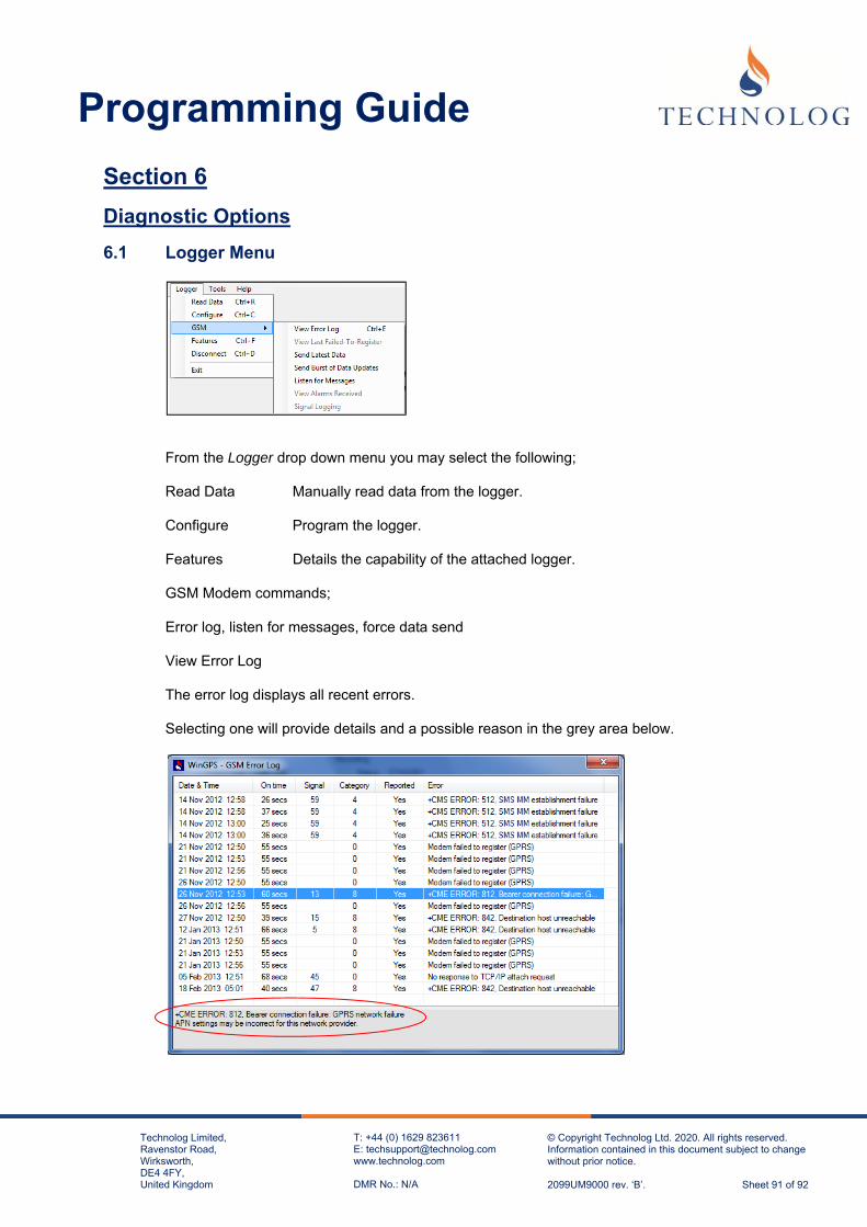
Programming Guide
Technolog Limited, Ravenstor Road, Wirksworth, DE4 4FY, United Kingdom
T: +44 (0) 1629 823611 E: [email protected] www.technolog.com DMR No.: N/A
© Copyright Technolog Ltd. 2020. All rights reserved. Information contained in this document subject to change without prior notice. 2099UM9000 rev. ‘B’. Sheet 91 of 92
Section 6
Diagnostic Options
6.1 Logger Menu
From the Logger drop down menu you may select the following;
Read Data Manually read data from the logger.
Configure Program the logger.
Features Details the capability of the attached logger.
GSM Modem commands;
Error log, listen for messages, force data send
View Error Log
The error log displays all recent errors.
Selecting one will provide details and a possible reason in the grey area below.

Programming Guide
Technolog Limited, Ravenstor Road, Wirksworth, DE4 4FY, United Kingdom
T: +44 (0) 1629 823611 E: [email protected] www.technolog.com DMR No.: N/A
© Copyright Technolog Ltd. 2020. All rights reserved. Information contained in this document subject to change without prior notice. 2099UM9000 rev. ‘B’. Sheet 92 of 92
6.2 Tools Menu
From the Tools drop down menu you can select: Terminal.
This will open up a blank screen.
To perform a signal test in the terminal window, press Shift + F1 on the keyboard. The modem will now start and run a signal test. Roaming SIM Cellos will tend to use the last network which they logged on to or the first on their available Network list.


![Panasonic...(l fffl) 00 ow-4S AHZTB 5mlè-lrX] 99 (1 1[$1) (IF—I +21fflfrj) AHZT uoo eow-4S QHZT sow-4S QHF ow-4S QHZTB • OW-4S (H-5ñ) (l /2BD&Ë) ow-4S (lffl) 00 ow-4S QHFB AHF](https://img.dokumen.tips/doc/110x75/60e6a246ed04070ec45dd6dc/panasonic-l-fffl-00-ow-4s-ahztb-5ml-lrx-99-1-11-ifai-21fflfrj.jpg)


![[Cello Plus_PT] Cello Introduction_Eng](https://img.dokumen.tips/doc/110x75/58eebde01a28ab56348b467f/cello-pluspt-cello-introductioneng.jpg)