Embed Size (px)
Citation preview

Supplementary Material (ESI) for Lab on a Chip. This journal is © The Royal Society of Chemistry 2012
1
Cell sorting by deterministic cell rolling
Sungyoung Choi, Jeffrey M. Karp and Rohit Karnik
I. Supplemental Materials and Methods
Materials Recombinant human P-selectin (sP-selectin monomer) was purchased from R&D Systems (Minneapolis, MN). Human promyelocytic
leukemia cell line (HL60) and human chronic myelogenous leukemia cell line (K562), Iscove’s modified Dulbecco’s medium (IMDM),
and fetal bovine serum (FBS) were obtained from American Type Culture Collection (ATCC, Manassas, VA). Dulbecco’s phosphate-
buffered saline (DPBS) was supplied by Mediatech Inc. (Manassas, VA). All other materials were obtained from Invitrogen Inc.
(Carlsbad, CA) and Sigma-Aldrich (St. Louis, MO), unless specified.
Cell culture and characterization
HL60 and K562 cells were cultured in IMDM supplemented with 20% FBS, 100 U/mL penicillin and 100 µg/mL streptomycin. Cell
concentration was maintained between 105 and 106 cells/mL. HL60 cells at passages between 10 and 40 were used for experiments. To
determine sorting performance (i.e. purity, throughput, and recovery), K562 cells were washed with DPBS and then stained with 5 μM
CFDA at 37 °C for 30 min only for separation of mixed samples of HL60 and K562 cells shown in Fig. 4B and 4C. For the experiments
in Fig. 4A, K562 cells were used without staining and did not exhibit cell rolling on P-selectin coated ridges. After staining, K562 cells
were washed twice with DPBS, and mixed with HL60 cells before each sorting experiment. HL60 cells were normally used without
staining. For taking the sorting video (Video S2), HL60 cells were washed with DPBS and then stained with 5 μM CellTracker at 37 °C
for 30 min. After staining, the cells were washed twice with DPBS, and mixed with K562 cells. There was no observable difference in
cell rolling behavior between stained and unstained HL60 cells, or between stained and unstained K562 cells. The sorted cells were
collected separately by using 2.0-mL centrifuge tubes and analyzed with a fluorescence-activated cell sorter (FACS; Accuri Cytometers,
Inc., MI). Sorting recovery was calculated as the number of collected target cells in each outlet (HL60 for the outlet A and K562 for the
outlet B) divided by the total number of each cell type injected.
Device fabrication Microfluidic devices were fabricated in a multilayer structure for scalable parallelization in which multiple sorting layers could be
sandwiched between the top injection layer and the bottom collection layer (Fig. S2). Each layer of poly(dimethylsiloxane) (PDMS) was
separately cast from microfabricated photoresist molds and then selectively punched to provide fluid interconnections with other layers.
The perforated layers were exposed to oxygen plasma for 40 s, and irreversibly assembled by sequentially stacking the collection layer,
sorting layers, and the injection layer. This method allows for easy addition of more sorting layers as required. Each sorting layer
comprised ten microchannels, each further comprising a focusing and a sorting channel (Fig. S3). The focusing channel had 80 focusing
ridges with θf = 60°, df = 35 µm, and gf = 35 µm (Fig. S3). The sorting channel comprised 51 sorting ridges with ds = 150 µm and gs =
150 µm for θs = 20°, and with ds = 75 µm and ds = 75 µm for θs = 45° (Fig. S3). The devices with θs = 20° were used for experiments,
unless specified. We tailored the channel gap, hg = 26 µm to be in the range d < hg < 2.5d so that the cell motion and interaction with the
ridges can be limited by steric hindrance, where d is the cell diameter of 11.7 ± 1.5 µm (HL60) and 14.6 ± 1.4 µm (K562).16
Master molds for each layer were made by patterning SU8 photoresist (Microchem Corp., Newton, MA). The master mold which
contained thick channel features (244.8 ± 30.6 µm in height) for cell injection and collection was formed on a silicon substrate in single
photolithographic process. Two-step photolithographic techniques were used to define two-layered features for cell sorting. The first
layer of photolithography defined the main linear-channel structures (hg, 26.0 ± 1.0 µm in depth); the second layer was aligned to lie on
top of the channel structures in the first layer and defined the pattern of slant ridges (ht, 62.6 ± 2.3 µm in depth).
The microfluidic conduits in each layer were carefully designed to uniformly distribute and collect cells. The sub-millimeter-scale
channels in the injection and collection layers were designed to have negligible pressure drop, and most of the pressure drop occurred
through the pressure dump resistors connected to the end of each separation channel (Fig. S3). The pressure drop for a rectangular
channel is given byS1
where W is the width of the channel, H is the height of the channel, a is a dimensionless parameter that depends on aspect ratio (W/H), µ
is the viscosity, Q is the volumetric flow rate, and L is the channel length. The calculated ratio of the pressure drop in the injection and
sorting channels to the pressure-dump channels was roughly 1:110, sufficiently high for the fluid to be distributed uniformly through the
parallel sorting channels.
Square posts of 50 µm × 50 µm, spaced 50 µm apart were fabricated in PDMS (58.9 ± 2.0 µm in depth) to examine the difference in
the trajectories of the rolling and non-rolling cells at the corners of the posts.
Electronic Supplementary Material (ESI) for Lab on a ChipThis journal is © The Royal Society of Chemistry 2012

Supplementary Material (ESI) for Lab on a Chip. This journal is © The Royal Society of Chemistry 2012
2
Experimental setup The assembled device was degassed in a vacuum chamber for 20 min, filled with P-selectin solution (cp = 1.5 µg/mL, unless specified)
by pipetting, and then incubated at room temperature. After 3 h incubation, the device was washed with 1% bovine serum albumin
(BSA). The inherent hydrophobicity of PDMS can facilitate protein physisorption although covalent immobilization of P-selectin
enhances its functional stability on surface.S2 Stable, reliable cell rolling for at least 3 h observed in the device shows that selectin
physisorption on PDMS substrates is sufficient for proof-of-concept studies.
Cells (~1 × 10⁵ to 2 × 10⁵ cells/mL) were flowed into the device at 50 to 110 µL/min using a syringe pump (KD Scientific Inc.,
Holliston, MA). Cell rolling and sorting were recorded using a high-speed camera (EX-F1; CASIO, Japan) mounted on inverted
microscopes (TE2000-U and TS100; Nikon, Japan). Visualization of flow patterns was performed using streak images of 1-µm diameter
fluorescent polystyrene beads (Invitrogen Inc.), which were estimated to have negligible inertial effects (particle Reynolds number ~10-4)
under the device operating conditions. Particles flowing near either the top or bottom surface of a sorting channel could be discerned by
adjusting the focal plane of the objective.
Numerical simulation Flow simulations were performed to calculate the maximum shear stress on the slant ridges where cells can tether and roll, and to
visualize streamlines in the channels. Commercial finite element analysis software (COMSOL Multiphysics 3.4) was used to solve three-
dimensional models (focusing and sorting channels) in the "Incompressible Navier-Stokes Mode." No-slip boundary conditions were
applied at the channel walls. The velocity at the inlet was set to have a parabolic profile and the pressure at the outlet was set to zero. The
channel for simulation was 670 µm in width and 63 µm in depth with a gap between the top surfaces of the SR and the channel, hg = 26
µm, a ridge interval, gs = 150 µm, and a ridge length, ds = 150 µm (Fig. S3 and S5). The first eight and nine ridges arranged in order of
decreasing widths by 5 µm from the initial width of 640 µm were simulated.
II. Supplemental Discussion
Flow visualization Visualization of flow patterns was performed using streak images of 1-µm diameter fluorescent polystyrene beads in the device with θs =
20°. Flow visualization with 1-µm particles revealed that the geometry-driven flow circulation was induced and composed mainly of two
oppositely flowing currents (Fig. S1). Above the top surface of the ridges, the flow circulates from the sorting/gutter side to the focusing
side, while within the trenches, the flow circulates in the opposite direction towards the gutter side. This flow pattern directs cell rolling
from the sorting ridges to the channel floor and out towards the gutter (Fig. 2A).
Sorting efficiency (ηs) dependence on ridge angles Previous studies have shown that the degree of non-axial flow is maximized when the groove intersection angle θ = 45° and that it
decreases with deviation from this angle.12 Therefore, we investigated whether the sorting efficiency, ηs is influenced by change in the
angle of the sorting ridges (SR), θs. To conduct this experiment, we fabricated two different devices with θs = 20° and 45° (Fig. S3). We
found that there was no significant difference between the devices over shear stresses ranged from 3 to 9 dyn/cm2 (Fig. S7). In either
case, the fluid flow caused the cells to flow in the lateral direction and come into contact with the SR. Once the target cells tethered on
the SR, whether they sustained cell rolling was determined by shear stress, not θs (Fig. S7).
Effect of gravity on deterministic cell rolling The motion of cells is under the influence of buoyant and gravitational forces as well as hydrodynamic forces. However, we estimate that
gravitational forces are not significant in the device operation. The maximum fluid velocity through the grooved region is ~3.5 mm/s for
the sorting condition (Fig. S5). Assuming Stokes drag, a cell with a diameter of 11.7 μm and a density of 1.05 g/cm3 has a settling
velocity of ~3.7 μm/s in water at 22 °C. The cell is estimated to settle down by a distance on the order of 100 nm under the influence of
gravity while traversing a sorting ridge (or ~2.5 μm while traversing 25 ridges before tethering), which is small compared to the channel
height of 62.6 μm. The flow rate in the focusing channel is an order of magnitude higher, and gravitational effects are expected to be
even smaller.
Effect of inertial forces on deterministic cell rolling To assess the influence of inertial forces on deterministic cell rolling, we examined the Reynolds number R = UmC/ν and particle
Reynolds number Rp = Umd2/νC, where Um is the maximum flow velocity, d is the particle diameter, ν is the kinematic viscosity, and C is
a characteristic dimension (the gap size, hg). Since the device is parallelized with 20 channels, a 70 μL/min injection rate for the sorting
corresponds to a flow rate of 3.5 μL/min in each channel. For this sorting condition, the above equations yield R = 0.09 and Rp = 0.02 for
the sorting channel, and R = 1.12 and Rp = 0.2 for the focusing channel. Inertial forces dominate particle motion at Rp of order 1.S3 Due
to the low Rp for the sorting channel, we can ignore the effect of inertial forces on deterministic cell rolling. In contrast, based on the high
Rp and the small dimensions (a/hg ~ 0.45) of the focusing channel, inertial forces may have an influence on the focusing processS4 and
their effect should be further investigated for better understanding.
Electronic Supplementary Material (ESI) for Lab on a ChipThis journal is © The Royal Society of Chemistry 2012

Supplementary Material (ESI) for Lab on a Chip. This journal is © The Royal Society of Chemistry 2012
3
Device design criteria Deterministic cell rolling employs a complex flow pattern that results in cell sorting in the presence of cell rolling interactions. For
deterministic cell rolling, the following two phenomena must occur under the same flow conditions and device geometry:
1. In the absence of cell rolling interactions, the cells must be focused by hydrophoresis.
For the cells to be focused by hydrophoresis, the channel dimensions should satisfy the following design guidelines: If the cell has a
diameter d, the gap size (hg) should typically be in d < hg < 2.5d and the total channel height (ht) should satisfy 2hg < ht.16 Stated in terms
of the trench depth (hr), the latter implies hg < hr. The first condition states that the gap must be greater than the cell diameter (to prevent
clogging), but not so large that the cells will follow individual streamlines. This part can be appreciated by considering the streamlines
shown in Fig. S5C, bottom panel. When a cell approaches the focusing region, the streamline that it follows enters into the trench.
However, the cell is displaced into another streamline above it, and thus keeps out of the trench. The displacement is proportional to the
cell radius; a point particle will just follow the streamline into the trench and go towards the sorting side. At the next ridge, the cell is
further displaced into another streamline above the present one, and so on. Thus, the cell must have a certain minimum size in order to
stay focused by hydrophoresis. The second criterion states that the trench must have sufficient depth to create a circulating flow pattern.
In addition, the trench angle cannot be too close to 0º or 90º for the circulation patterns to be created.
2. In the presence of cell rolling interactions, cells must be deflected into the trenches and sorted to the gutter side.
Due to the nature of the streamlines near the focusing side, we hypothesize that cells will be directed into the trench as long as conditions
for stable rolling are maintained. Shear stress on the order of 0.1-10 dyn/cm2 can typically support stable rolling of cells on selectins;
therefore, the flow rate must be set to achieve this range of shear stresses. In addition, the trench must be deep enough and wide enough
to allow the cell to roll in it towards the sorting side, i.e. d < hr, and d < gssinθ, where gs is the groove spacing, and gssinθ is the width of
the trench (see Fig. S3). Prior studies on cell rolling suggest that the area of contact is typically in the range of 5 to 10 μm.S5 To ensure
the stable tethering of cells, the length (ds) of the sorting ridges should be larger than 10 μm. We set ds to 150 μm for stable tethering of
multiple cells without interference of each other. We also set the groove spacing (gs) to the same dimension with ds so that multiple cells
can roll in the trench without significant cell-cell interactions.
Application of deterministic cell rolling to other systems To develop deterministic cell rolling as a new technique for cell separation, we chose a robust and well-characterized system of HL60
cells rolling on P-selectin to verify the principle. Hematopoietic stem and progenitor cells have been studied for their specific separation
by CD34-mediated rolling adhesion on P-selectin.9 Myung et al. have shown that MCF7 cells, human breast cancer cells exhibit specific
rolling adhesion on E-selectin mediated by CD24.10 Several other receptor-ligand pairs are known to support cell rolling, including
molecules expressed on non-mammalian cells. While we anticipate that deterministic cell rolling will be extended to these and other cell
types, new applications will need to be developed on a case-by-case basis due to the need to tailor the surfaces to ensure cell rolling. In
cases where a specific affinity molecule that supports rolling is not available, tailoring of the surface may require selection or
identification of low-affinity adhesion molecules, other lectins, or co-immobilization of antibodies with selectins.S6 Cells may also
potentially be modified by labeling them with molecules that facilitate cell rolling23 or by expressing such molecules on the cell surface.
These approaches could potentially enable deterministic cell rolling to be extended to other cell systems of practical interest.
III. Supplemental Figures
Fig. S1 Flow visualization of the sorting channel with 1-µm fluorescent beads. The fluorescence images show the rotational pattern of
the flow streams in a clockwise direction as viewed from the x-axis. Scale bar, 200 µm.
Electronic Supplementary Material (ESI) for Lab on a ChipThis journal is © The Royal Society of Chemistry 2012

Supplementary Material (ESI) for Lab on a Chip. This journal is © The Royal Society of Chemistry 2012
4
Fig. S2 The four PDMS layers (an injection layer, two sorting layers, and a collection layer) were aligned and assembled together after
their exposure to oxygen plasma for 40 s. The photographs were three-dimensionally reconstructed for better illustration.
Fig. S3 Geometry of a single microfluidic channel comprising the narrow focusing channel and the wide sorting channel. The pressure
dump channels (100 µm in width) are connected at the end of the sorting channel so that most of the pressure drop occurs through them.
Thereby, the dump channels maintain a uniform flow distribution at each outlet junction in the parallel channel circuit.
Electronic Supplementary Material (ESI) for Lab on a ChipThis journal is © The Royal Society of Chemistry 2012

Supplementary Material (ESI) for Lab on a Chip. This journal is © The Royal Society of Chemistry 2012
5
Fig. S4 Adhesion of HL60 cells in the focusing channel. HL60 cells rolling in the focusing channel under steady state were counted from
the images taken with a long exposure time where flowing cells could not be observed. Some HL60 cells could tether on the focusing
ridges even at the high shear stresses over 30 dyn/cm2 but could not sustain rolling. The flow rate of the cells being introduced into the
channel was ~100 to 220 cells/s. No channel clogging by the rolling cells was observed during separation. Error bars, s.d. (n = 3).
Electronic Supplementary Material (ESI) for Lab on a ChipThis journal is © The Royal Society of Chemistry 2012
Supplementary Material (ESI) for Lab on a Chip. This journal is © The Royal Society of Chemistry 2012
6
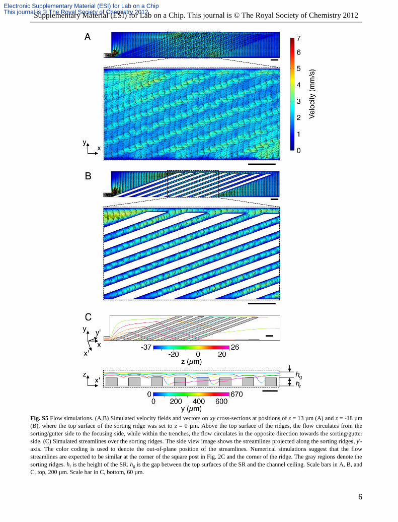
Fig. S5 Flow simulations. (A,B) Simulated velocity fields and vectors on xy cross-sections at positions of z = 13 µm (A) and z = -18 µm
(B), where the top surface of the sorting ridge was set to z = 0 µm. Above the top surface of the ridges, the flow circulates from the
sorting/gutter side to the focusing side, while within the trenches, the flow circulates in the opposite direction towards the sorting/gutter
side. (C) Simulated streamlines over the sorting ridges. The side view image shows the streamlines projected along the sorting ridges, y'-
axis. The color coding is used to denote the out-of-plane position of the streamlines. Numerical simulations suggest that the flow
streamlines are expected to be similar at the corner of the square post in Fig. 2C and the corner of the ridge. The gray regions denote the
sorting ridges. hr is the height of the SR. hg is the gap between the top surfaces of the SR and the channel ceiling. Scale bars in A, B, and
C, top, 200 µm. Scale bar in C, bottom, 60 µm.
Electronic Supplementary Material (ESI) for Lab on a ChipThis journal is © The Royal Society of Chemistry 2012

Supplementary Material (ESI) for Lab on a Chip. This journal is © The Royal Society of Chemistry 2012
7
Fig. S6 Number of rolling HL60 cells exiting each trench (counted per min) in the P-selectin-coated device (see Fig. 3B). Mean lateral
positions of the HL60 cells in the BSA-passivated channel at each trench in Fig. 3A are also shown (blue triangles).
Fig. S7 Effect of the angle of the sorting ridge, θs and shear stress intensity on the sorting efficiencies of HL60. There is no observable
variation of the sorting efficiency of HL60 cells with change in the sorting ridge angle. Error bars, s.d. (n = 3).
IV. Video Captions
Video S1 Deterministic cell rolling of HL60 cells at σ = 3.4 dyn/cm2 and cp = 1.5 µg/mL. This video is shown in real time and describes
the rolling sequence of two HL60 cells in order of (1) tethering, (2) rolling on the vertical wall, (3) rolling on the bottom wall, and (4)
detaching.
Video S2 Sorting of HL60 (red) and K562 (green) cells at σ = 3.4 dyn/cm2 and cp = 1.5 µg/mL. This video is shown in real time.
V. References
S1 C. J. Morris and F. K. Forster, Exp. Fluids, 2004, 36, 928.
S2 S. Hong, D. Lee, H. Zhang, J. Q. Zhang, J. N. Resvick, A. Khademhosseini, M. R. King, R. Langer and J. M. Karp, Langmuir, 2007,
23, 12261.
S3 D. D. Carlo, D. Irimia, R. G. Tompkins and M. Toner, Proc. Natl. Acad. Sci. U. S. A., 2007, 104, 18892.
S4 W. Mao and A. Alexeev, Phys. Fluids, 2011, 23, 051704.
S5 C. Dong and X. X. Lei, J. Biomech., 2000, 33, 35.
S6 J. H. Myung, C. A. Launiere, D. T. Eddington and S. Hong, Langmuir, 2010, 26, 8589.
Electronic Supplementary Material (ESI) for Lab on a ChipThis journal is © The Royal Society of Chemistry 2012

![A RANDOMIZED SORTING ALGORITHM ON THE BSP MODELalexg/pubs/papers/avgcsrs11.pdfPreviously known results on BSP sorting include deterministic [1, 6, 16, 26] and randomized [14, 24, 20]](https://img.dokumen.tips/doc/110x75/600b843b5d0f60798d1af9d6/a-randomized-sorting-algorithm-on-the-bsp-model-alexgpubspapers-previously-known.jpg)


![ÁRAMLÁSI CITOMETRIA [FLOW CYTOMETRY, FACS (fluorescence activated cell sorting)]](https://img.dokumen.tips/doc/110x75/56814883550346895db596a6/aramlasi-citometria-flow-cytometry-facs-fluorescence-activated-cell-sorting.jpg)