Embed Size (px)
Citation preview

CEILING CASSETTE DUCTLESS SYSTEM
INSTALLATION MANUAL
Models:
CAS12HP230V1AC -12,000 BTUH CAS18HP230V1AC -18,000 BTUH CAS24HP230V1AC - 24,000 BTUH
Thank you for choosing the Gree Ceiling Cassette for your Ductless Heat Pump System Please read this installation manual carefully before installing and starting up the Ductless System with Ceiling Cassettes. Take a moment to fill out the product and installation form on the back cover. Retain both the manual and installation record for future reference. Table of Contents. Safety Precautions 3
System Requirements 4
Nomenclature 4
Suggested Tools 5
Product Dimensions 6
Product Overview 7
Installation of Ceiling Cassette 8
Installation of Refrigerant Piping 10
Installation of Condensate Piping 12
Installation of Power & Wiring 13
Installing of Wired Controller 14
Installing of Decorative Grille 16
Start Up and Check Out 18
Troubleshooting 19
2

GENERAL SAFETY PRECAUTIONS Please read the following before installation Recognize safety information. This is the safety-alert symbol. When you see this symbol on the unit and in instructions or manuals, be alert to the potential for personal injury. Understand these signal words: DANGER, WARNING, and CAUTION. These words are used with the safety-alert symbol. DANGER identifies the most serious hazards which will result in severe personal injury or death. WARNING signifies hazards which could result in personal injury or death. CAUTION is used to identify unsafe practices which may result in minor personal injury or product and property damage. NOTE is used to highlight suggestions which will result in enhanced installation, reliability, or operation.
WARNING
Heat pumps, air conditioners & heating equipment should be installed, started up, and serviced only by qualified installers and/or service technicians. Air conditioning, heat pumps and refrigeration systems are hazardous due to high voltage electrical components, high refrigerant pressures, and moving parts.
WARNING
ELECTRICAL SHOCK HAZARD Failure to follow this warning could result in personal injury or death. Before installing, servicing or modifying the system, the main electrical disconnect switch must be in the OFF position. There may be more than one disconnect switch. Lock out and tag all switches with a warning label.
General Safety Precautions
• A dedicated power supply circuit should be used in accordance with local electrical safety regulations and National Electrical Codes (NEC).
• Ensure that the entire system is reliably grounded. • Use proper size circuit breaker to protect equipment against short circuit and overload conditions. • The system must be positioned at least 5 feet from flammable combustive liquids. • Observe all local codes and regulations.
NOTE: Your actual equipment and related devices may differ from the images shown in this manual. This appliance is not intended for use by children without responsible adult supervision. Proper care should be taken to ensure safety.
3

SYSTEM REQUIREMENTS PIPE SIZE:
Model # Capacity Size (Btu) Voltage Liquid Line Suction/Gas
Line Net/Gross
Weight
CAS12HP230V1AC 12,000 208/230 - 1ph 60 hz 1/4-in (6mm) 3/8-in (9.5mm) 44/51 lbs. CAS18HP230V1AC 18,000 208/230 - 1ph 60 hz 1/4-in (6mm) 1/2-in (12-mm) 48/55 lbs. CAS24HP230V1AC 24,000 208/230 - 1ph 60 hz 3/8-in (9.5mm) 5/8-in (16-mm) 66/84 lbs.
INTERCONNECTING CABLE: Recommended 14/4 AWG stranded bare copper conductors THHN 600V unshielded wire Note: Use shield cable if installation is in close proximity of RF and EMI transmitting devices. CONDENSATE DRAINAGE: Recommended condensate drainage system use pipe either the same diameter or with the diameter larger (excluding the raising section) than that of the connecting pipe (nominal diameter 1-in, outside diameter 1-1/4-in.) Note: Insulate condensate all condensate drain pipes to prevent sweating and possible water damage. NOMENCLATURE:
Series DesignationProduct TypeS - System O - Outdoor units
CAS - Ceiling Cassette H - Indoor High Wall D - Indoor DuctC - Indoor Cassette
Cooling Capacity F - Indoor Floor/Ceiling12 - 12,000 BTUH18 - 18,000 BTUH Revision Level24 - 24,000 BTUH(ect..) Style/Color Designation
Model TypeAC -Cooling Only Electrical RatingHP -Heat Pump 230V - 208/230V 60Hz 1PHHC - Heat/Cool 115V - 115V 60Hz 1PH
Example: CAS18HP230V1AC
CAS 42 HP 230V 1 A C
4

SUGGESTED TOOLS
Standard Wrench
Adjustable/Crescent Wrench
Torque Wrench Hex Keys or Allen Wrenches Drill & Drill Bits Hole Saw Pipe Cutter Screwdrivers(Phillips&Flatblade)
Manifold and Gauges Level R410A Flaring Tool Clamp on Amp Meter Vacuum Pump Safety Glasses
Work Gloves Refrigerant Scale Micron Gauge
5

PRODUCTS DIMENSIONS Ceiling Cassette Dimensions Units: Inch (mm)
Minimum Indoor Clearance
Units: Inch (mm)
6

PRODUCT OVERVIEW
XK-19 Tether Wired Controller
Remote Controller
7
INSTALLATION OF CEILING CASSETTE Step 1 - Selecting Location for Ceiling Cassette Unit Select a location that allows for the following:
• Ensure the installation complies with the installation minimum dimensions and meets the minimum and maximum connecting piping length and maximum change in elevation.
• Air inlet and outlet will be clear of obstructions, ensuring proper airflow throughout the room. • Condensate can be easily and safely drained. • All connections can be easily made to outdoor unit. • Indoor unit is out of reach of children. • A ceiling strong enough to withstand four (4) times the full weight and vibration of the unit. • Filter can be easily accessed for cleaning. • Leave enough free space to allow access for routine maintenance. • Install at least 10 ft. (3 m) away from the antenna of TV set or radio. Operation of the air
conditioner may interfere with radio or TV reception in areas where reception is weak. An amplifier may be required for the affected device.
• Do not install in a laundry room or by a swimming POOL. • The location meets all the minimum clearance dimensions and the requirements of the schematic
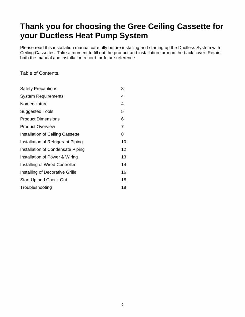
diagram. Step 2 - Laying Out Location
• Locate the factory supplied installation template included in carton. • Use the template to make an opening in the ceiling for the ceiling cassette main body. • Mark the position of the hanger bolts, refrigerant lines and condensate drain pipes,
interconnecting cable and wired remote controller wires ( if applicable). .
8

INSTALLATION OF CEILING CASSETTE Step 3 – Installation of Mounting Hangers Depending on the type of ceiling, attached the threaded hanger bolts (field supplied) securely to the ceiling or support stud. Before lifting Ceil Cassette unit to the installation location, insert the upper nuts, flat washers (with insulation), flat washers (without insulation), lower nuts and locking nut (double) on the threaded hanger bolts as show in diagram. Note: Fit the washer with cushion so that the insulation faces downward. Step 4 - Installation of Ceiling Cassette Lift the Ceiling Cassette main body unit to the threaded hanger bolts. Insert the unit mounting brackets between washers and then fasten it securely. Step 5 - Confirming Position of Ceiling Cassette
1. Adjust height of Ceiling Cassette main body to align with false ceiling. Be sure to confirm this, otherwisecondensation may form due to air leakage, etc. Adjust mounting nuts as needed.
2. Confirm that the Ceiling Cassette main body is horizontally leveled. Adjust mounting nuts as
needed.
3. After checking the positioning of the Ceiling Cassette main body, tighten the nuts of the hanger bolts securely to fasten the Ceiling Cassette main body in place.
4. The installation template may be used as a protective sheet toprevent dust from entering the
Ceiling Cassette when the decorative grilles are left unattached during the installation.
9

INSTALLATION OF REFRIGERANT PIPING Step 6 – Drill Hole in Wall
1. Find and mark the proper location for the wall hole. Use the table below for the recommended wall hole size.
Model # Capacity Size (Btuh)
Wall Hole Size (Diameter) in mm
CAS12HP230V1AC 12,000 2 1/4 55 CAS18HP230V1AC 18,000 2 3/4 66 CAS24HP230V1AC 18,000 2 3/4 66
2. Cut the wall hole with a 5° to 10° downward slant to the outdoors.
3. Insert a wall sleeve into hole to prevent damage to refrigerant pipes, insulation, condensate drain
hose and wiring.
4. Proper weather proofing of the wall surface and wall sleeve is essential to assure a trouble-free installation. Apply sealant, caulking or equivalent weather proofing material around the perimeter of the wall sleeve (interior & exterior) to eliminate outdoor air and water leaks into the living space. Note: Expandable foam insulation may be added to fill large wall gaps. Apply per manufacturer's instructions.
Wall Hole Diagram
10

INSTALLATION OF REFRIGERANT PIPING Step 5 - Piping Connections to Ceiling Cassette
CAUTION Use refrigeration grade piping ONLY. Uses of other pipingwill void the Manufacturer’s Warranty.
Piping Preparation
1. Do not open service valves or remove protective caps on pipes until all connections are made.
2. Keep tubing free of dirt, sand, moisture and contaminants.
3. Insulate each refrigerant pipe and condensate hose with minimum 3/8” (10 mm) wall thermal pipe insulation. NOTE: Insulate condensate hose and/or pipes to prevent sweating which may cause water stains or wall damage.
4. Bind refrigerant pipes, the condensate hose and interconnecting cable together with cable ties at
12-inch intervals. Connecting Refrigerant Pipes to Ceiling Cassette
1. Feed refrigerant pipes, drain hose and interconnecting wires assembly through wall hole from outdoor to the Ceiling Cassette.
2. Adjust the length and carefully bend refrigerant pipes to meet indoor unit refrigerant pipe connections with proper tools to avoid kinks.
3. Apply a small amount of refrigerant oil to the flare connection on the refrigerant pipes.
Torque Table
Pipe Diameter inch (mm)
Nut Size inch (mm)
Tightening Torque
ft-lbs N-m 1/4 (6.35) 1/4 (17) 10 to 13 14 to 18 3/8 (9.5) 3/8 (22) 25 to 30 34 to 42 1/2 (12.7) 1/2 (25) 36 to 45 49 to 61 5/8 (15.9) 5/8 (29) 50 to 60 68 to 82
4. Properly align piping and tighten flare nut using a standard wrench and a torque wrench as shown in figure to the below. Carefully tighten flare nuts to correct torque level referring to the following Torque Table:
NOTE: Over tightening may damage flare connections and cause leaks.
5. Apply pipe insulation to entire refrigerant pipe and joints to prevent sweating.
11
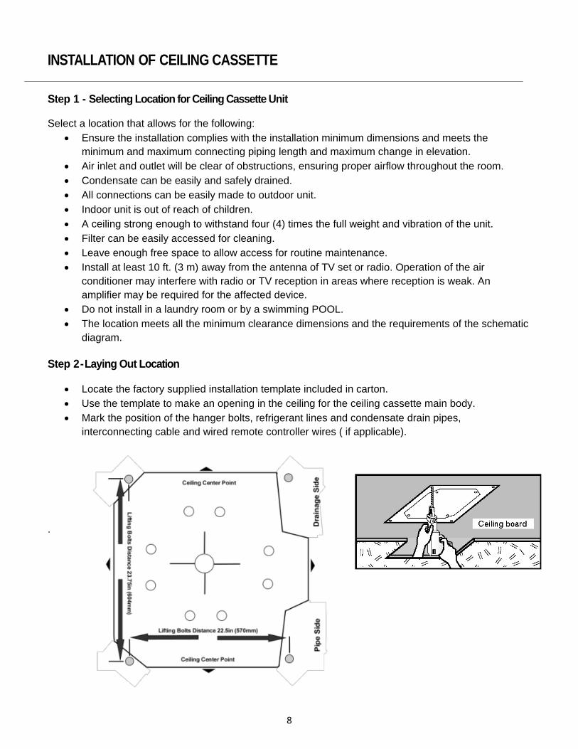
INSTALLATION OF CONDENSATE PIPING Step 6 - Piping Connections to Outdoor Unit See Installation Instructions shipped with the outdoor unit. Step 7 - Condensate Pipe Connections
WARNING Observe all local sanitary codes when installing condensate drains. It’s recommended to build the condensate drain system with hard polyvinyl chloride (PVC) pipe and matching connectors. Use pipe either the same diameter or with the diameter larger (excluding the raising section) than that of the connecting pipe. The Ceiling Cassette drainage port diameter is 1-in (25 mm) OD. Pitch the condensate drain pipes at a gradual 2.5% pitch (Example: ¼-in drop over a10-in length) without obstructions. Use pipe hanger/brackets to support the condensate drain pipe from dropping. Insulate all condensate drain pipe to prevent sweating and possible water damage. Gravity Drainage SystemDrainage System with P-Trap & Vent The following is the recommended condensate drainage system for multiple units share a common drain line.
12

INSTALLATION OF POWER AND WIRING If a gradual pitch from the drainage port is not obtainable, the Ceiling Cassette contains an internal condensate pump with limited head or lift. The condensate drain pipe may have a vertical height of 11-in. (280 mm) maximum above the unit drainage port within the first 12-in (305 mm) as long as the remaining condensate drain pipe gradually descends from that point and aligned with drainage port. Use an auxiliary condensate pump with float valve for vertical height greater than of 11-in. (280 mm) above the unit drainage port. A float valve is recommended to shut off the system if the auxiliary pump fails. Step 8 - Electrical Connections to Ceiling Cassette
WARNING
Disconnect all electrical power to unit including disconnects, fuses and circuit breakers.
1. Adjust the length of the interconnecting wires so that it can easily reach the Ceiling Cassette electrical control box.
2. Open electrical control box cover and route the interconnecting wires to field wiring terminal block.
NOTE: The indoor unit is powered from the outdoor unit, depending on local code, a disconnect switch may need to be installed to a power supply circuit.
3. Secure interconnecting wires to the terminal block per connection diagram. NOTE: Record wire colors and terminal references for uses with Outdoor Unit wire connections.
13

INSTALLATION OF POWER AND WIRING
4. Secure all wires inside wire clamp/strain relief. Verify wires are secure, not loose and no external
force on wires affects the connections at the terminals.
NOTE: Crossing interconnecting wires will cause system malfunction and possible damage.
5. Replace field wiring cover on unit.
Local codes may require a disconnect switch within sight of the indoor unit. Use a DFS Disconnect Switch Accessory Kit (Part No: DFS-SWITCH-A) to break interconnecting wires going to the N(1), 2, 3, terminals on the indoor unit, as shown in the wiring diagram below:
Step 9 – Installing Wired Controller to Ceiling Cassette
1. Open decorative grille and locate 4 pin connector for wired controller on Ceiling Cassette main body
2. Route wired controller wires to 4-pin connector and connect wired controller to ceiling cassette. NOTE: The maximum wire length is 65-ft (20m) for a Wired Controller.
1. Replace decorative grille being careful not to pinch wires.
2. Remove back plate from Wired Controller.
14

INSTALLATION OF POWER AND WIRING
3. Mount Wired Controller backplate to wall (or electrical junction box, if required) with screws provided.
4. Plug wire cable from Ceiling Cassette into the back of Wired Controller.
5. Attach the Wired Controller to backplate on the wall. Step 10 - Outdoor Unit Wire Connections See Installation Instructions shipped with the outdoor unit.
15

INSTALLATION OF FRESH AIR VENTILATION (24,000 Btuh Size Only) The 24,000 Btuh Ceiling Cassette can be used for fresh air ventilation.
1. Location the pre-punched knockouts hole for ventilation duct on ceiling cassette unit. Do not remove the knock out and open hole at this point.
2. Using Fig. 38, Remove the factory installed insulation on the outside of ceiling cassette where the
pre-punched knockouts was located.
3. Remove the pre-punched knockouts and open the ventilation duct hole. Refer to Fig. 38. Be careful not to damage internal parts such as the heat exchanger coil.
4. Install field supplied ductwork. Recommended ductwork is either an insulated flex duct, or
insulated sheet metal duct suitable for working temperatures up to 140 deg F (60 deg C).
CAUTION Ventilated air must not exceed 10%of the total airflow or problems with operation will result.
5. Use a field-supplied power ventilation fan to increase airflow to meet job requirements. Follow the
manufacturer’s installation instructions provided with the power ventilation kit.
6. Install a field supplied air filter to prevent dust and dirt from entering the ceiling cassette unit and fouling indoor coil.
7. Install a field supplied mechanical duct damper to close during shutdown periods.
8. All metal ductwork should be covered with insulation to prevent condensation forming.
16

INSTALLING DECORATIVE GRILLE Step 11 – Mounting Decorative Grille
1. Carefully unpack decorative grille and align the decorative grille to the ceiling cassette main body
2. Temporary attach the decorative grille to the ceiling cassette main body at two (2) corner points.
3. Locate the two (2) Swing Louver electrical connectors on the decorative grille.
4. Connect both Swing Louver connectors on decorative grille to matching connectors on the ceiling cassette body.
5. Complete the Decorative grille attachment by hooking the remaining two (2) corners to the Ceiling Cassette main body.
NOTE: Be careful not to pinch the swing louver motor wires between the decorative grille and ceiling cassette main body.
6. Find the four (4) height adjustment screws located on the corners of the decorative grille. Use the four (4) height adjustment screws to adjust gap between decorative grille and ceiling cassette body reduced to 1/4-in (6mm) to 3/8-in (9mm). Make certain the decorative grille is not distorted by excessive tightening.
17

INSTALLING DECORATIVE GRILLE
7. Verify the seal between decorative grille and Ceiling Cassette main body istight all the way around the unit to prevent air leak. Use the height adjustment screws to adjust the gap.
`
NOTE: Improper gap to seal between decorative grille and Ceiling Cassette main body may cause condensation.
The decorative grille aligns correctly with false ceiling. The is a seal between decorative grille and false ceiling must be between 1/4-in (6mm) to 3/8-in (9mm) all the way around the unit. Adjust the hanger bolts and nuts to change gap.
Step 12 – Start Up & Check Outdoor Unit See Installation Instructions supplied with the outdoor unit.
18

START UP AND CHECK OUT Step 13 – Start Up & Check Ceiling Cassette
1. Continue with the Ceiling Cassette after verifying Outdoor Unit Operation
2. Turn Ceiling Cassette ON using either the remote control or wired controller. Verify the “ON” LED lights up on the Ceiling Cassette.
3. Select Cooling Mode using either the remote control or wired controller.
Verify the “Green” LED lights up on the Ceiling Cassette.
4. Change fan speeds either the remote control or wired controller. Verify the fan speed change.
Step 14 - Test Condensate Disposal System The Ceiling Cassette contains a condensate pump and float switch. Test the condensate disposal system by the following:
1. Remove grille and frame from the unit and find the drainage port. 2. Locate and Remove the access cover. 3. Place the unit in cooling mode and wait until the compressor turns on. 4. Slowly add 20 to 24 oz. of a water bottle to the drain pan. 5. Water must drain freely from the unit with condensate pump energized. If not, check the pipe
slope or see if there are any pipe restrictions.Verify all piping joints are leak free. NOTE: This unit is equipped with a safety float switch to de-energize the compressor if the water level get too high.
19

TROUBLESHOOTING
WARNING Do not attempt any repairs on the unit yourself. Incorrect repair can cause shock or fire. Always call a qualified service professional. Using these troubleshooting suggestions can save time when you contact the qualified service professional.
PROBLEM CAUSE/SOLUTION
System does not restart. Cause: The system has a built-in three-minute delay to prevent short and/or rapid cycling of the Compressor.
Solution: Wait three minutes for the protection delay to expire. Indoor unit emits Cause: Typically unpleasant odors are the result of mold or mildew forming on the coil unpleasant odor surfaces or air filter. when started Solution: Wash indoor air filter in warm water with mild cleaner. If odors persist, contact a qualified service professional to clean the coil surfaces. You hear a Cause: It is normal for the system to make “water flowing” or “gurgling” sounds from “water flowing” sound. refrigerant pressures equalizing when the compressor starts and stops. Solution: The noises should discontinue as the refrigerant system equalizes after two or three minutes. A thin fog or vapor Cause: It is normal for the system to emit a slight fog or water vapor when cooling coming out of the indoor extremely humid warm air. unit when system is running. Solution: The fog or water vapor will disappear as the system cools and dehumidifies the room space. You hear a slight cracking sound when the system stops or starts.
Cause: It is normal for the system to make “slight cracking” sounds from parts expanding and contracting during system starts and stops.
Solution: The noises should discontinue as temperature equalizes after two or three minutes.
The system will not run. Cause: There are a number of situations that will prevent the system from running. Heating or cooling Solution: Check for the following: not running efficiently. • Circuit breaker is “tripped” or “turned off.” • Power button of remote is not turned on. • Batteries in the remote controller are low. • Remote controller is in sleep mode or timer mode. • Otherwise, you should contact a qualified service professional for assistance. The system will not run. Cause: With routine maintenance, your system is designed for years of peak efficiency. Heating or cooling Solution: Check the following: not running efficiently. • Remove obstructions blocking airflow into the room. • Clean dirty or blocked indoor air filter that is restricting airflow into the system. • Seal outdoor air leaks in the room space from door or windows. • Relocate (if possible) other heating sources in the room space.
20

TROUBLESHOOTING The Gree Ductless Mini-Splits units have onboard diagnostics. Informational and error codes will be displayed on the Wired Controller display. Informational codes are not signs of system malfunctions or failures. The following is a list of system informational codes and descriptions:
Description Info
Code Possible Causes Mode Conflict E7 Some Indoor Units are Requesting Heat and Some cooling. Defrosting H1 Defrosting Indoor Coil during Heating Mode
Error codes are an indicator of a system malfunction or failure. The following list of error codes and descriptions:
Equipment Fault Error
Codes Possible Causes Indoor Ambient Temp. Sensor F1 Short/Open of the Indoor Ambient Temperature Sensor Indoor Evaporator Temp Sensor F2 Short/Open of the Indoor Evaporator Temperature Sensor Outdoor Ambient Temp Sensor F3 Short/Open of the Outdoor Ambient Temperature Sensor Outdoor Coil Temp Sensor F4 Short/Open of the Condenser Coil Temperature Sensor Outdoor Discharge Air Temp Sensor F5 Short/Open of the Outdoor Discharge Temperature Sensor Liquid Valve Inlet Temp Sensor b5 Short/Open of the Liquid Valve Temperature Sensor Suction/Gas Valve Outlet Temp Sensor b7 Short/Open of the Gas/Suction Valve Temperature Sensor Indoor Configuration Jumper C5 Missing Configuration Jumper on Indoor Control Board High Pressure Protection E1 Too much refrigerant or High Ambient conditions or low airflow. High Discharge Temp Protection E4 Compressor Discharge High Temperature Protection High Current Protection E5 Power Supply is Not Stable and Voltage Range too large Communication Error E6 Communication Failure or mis-wired between Indoor/Outdoor Overload Protection E8 Overload Protection Indoor Condensate Full E9 Indoor condensate pan is full and needs to be drained. Compressor Overheat Protection H3 Compressor Thermal Overload Protection IPM Protection H5 Module Current Protection(namely IPM Protection) Indoor fan Malfunction H6 Indoor Fan Stopped or Running too Slow Motor Desynchronizing H7 Compressor Desynchronizing PFC Error Hc PFC Protection Startup Failure Lc Compressor Startup Failure Phase Loss Ld Compressor phase Failure/Reverse Protection Indoor/Outdoor Mismatch LP Indoor and Outdoor Units Unmatched (Model or Capacity) Compressor Current Protection P5 Phase Over-Current Protection Radiator Temp Sensor Error P7 Short/Open Circuit of the Module Temperature Sensor Radiator Overheat Protection P8 Module Temperature Protection 4-Way Valve Malfunction U7 Bad Connection, Solenoid Failure or Valve Malfunction
For additional error codes not listed above, see the Gree Multi+ Service &Troubleshooting manual.
21


PRODUCT & INSTALLATION RECORD For your convenience, please record the model and serial numbers of your new equipment in the spaces provided. This information, along with the installation data and dealer contact information will be helpful should your system require maintenance or service. UNIT INFORMATION Model No. ___________________________________ __ Serial No. _____________________________ ________ INSTALLATION INFORMATION Date Installed: _____________________________________ DEALERSHIP/INSTALLER INFORMATION Company Name: _____________________________________ Address: ________________________________ _____ Phone Number: _____________________________________ Technician Name: _____________________________________
Gree Electric Appliances, Inc. © 2014 Cat No: DFS-CASS-HP-1IN


![(Microsoft PowerPoint - [v 1.A] Ceiling Cassette [\310\243\310\257](https://img.dokumen.tips/doc/110x75/5872133f1a28ab9c518be2da/microsoft-powerpoint-v-1a-ceiling-cassette-310243310257-.jpg)