Embed Size (px)
Citation preview

CEBAF/ILC Inverted GunM. Poelker, P. Adderley, J. Clark, J. Grames, J. Hansknecht,
M. Stutzman, R. Suleiman, K. Surles-Law

CEBAF 100kV polarized electron source
• Two-Gun Photoinjector - One gun
providing beam, one “hot” spare
• vent/bake guns – 4 days to replace
photocathode (can’t run beam from
one gun while other is baking)
• Activate photocathode inside gun – no
HV breakdown after 7 full activations HV breakdown after 7 full activations
(re-bake gun after 7th full activation)
• HV breakdown after just 4 activations
when Ti-alloy electrodes are used
• Infrared drive laser light: operate at
bandgap
• Extract ~ 2000 Coulombs per year
• Beam current ~ 100uA, laser 0.5mm
dia., lifetime: ~ 100C, 1x10⁵ C/cm2

Preparing for Demanding New Experiments
Vent/Bake Guns: need improvement
– Difficult to meet demands of approved high
current/high polarization experiments like PRex
(100uA) and Qweak (180uA and 1-year duration).
– Our vent/bake guns can provide only ~ 1 week
operation at 180uA
– 12 hours to heat/reactivate, four days downtime to
replace photocathode
Design Goal for New Gun: One Month Uninterrupted Operation at 250uA, One Shift to
Replace Photocathode
Solution:
(1) LLGun for quick photocathode swap, (2) better vacuum and, (3) higher bias voltage

0
50
100
150
200
250
300
0 50 100 150 200
Ele
ctr
on
Bu
nch
len
gth
(ps)
Ave. Gun Current (µA)
Bunchlength Vs Gun Voltage 200KeV
115KeV
100KeV
85KeV
70KeV
0
50
100
150
200
250
300
0 50 100 150 200
Ele
ctr
on
Bu
nch
len
gth
(ps)
Ave. Gun Current (uA)
Electron Bunchlength vs Gun Voltage
115kV
100kV
85kV
70kV
Measurements at CEBAF/JLab PARMELA Simulation Results
Benchmarking PARMELA Simulation Results Against Beam-Based
Measurements at CEBAF/Jefferson Lab – work of Ashwini Jayaprakash, JLab
Similar Ave. Gun Current (µA)Ave. Gun Current (uA)
Message: Beam quality, including transmission, improves at higher gun voltage
0
10
20
30
40
50
60
70
80
90
100
0 50 100 150 200
Tra
nsm
issi
on
(%
)
Ave. Gun Current (uA)
Transmission vs Gun Voltage115kV
100kV
85kV
70kV
0
10
20
30
40
50
60
70
80
90
100
0 50 100 150 200
Tra
nsm
issi
on
(%
)
Ave. Gun Current (µA)
Transmission Vs Gun Voltage
200KeV
115KeV
100KeV
85KeV
70KeV
Similar
Trends
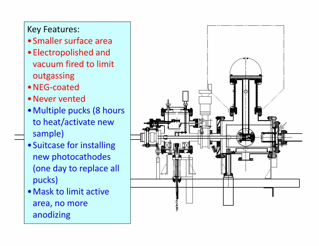
Key Features:
•Smaller surface area
•Electropolished and
vacuum fired to limit
outgassing
•NEG-coated
•Never vented
•Multiple pucks (8 hours
to heat/activate new to heat/activate new
sample)
•Suitcase for installing
new photocathodes
(one day to replace all
pucks)
•Mask to limit active
area, no more
anodizing

New CEBAF load-locked gun
Loading chamber
Preparation/activation chamber
HV chamber
“suitcase”
HV chamber
Vent/bake gun

Lifetime with Large/Small Laser SpotsTough to measure >1000 C lifetimes with 100-200 C runs!
1500350
2≈ 18
Expectation:
5
15
“Further Measurements of Photocathode Operational Lifetime at Beam Current > 1mA using an Improved 100 kV DC High Voltage GaAs Photogun,” J. Grames, et
al., Proceedings Polarized Electron Source Workshop, SPIN06, Tokyo, Japan

1mA at High Polarization*Parameter Value
Laser Rep Rate 499 MHz
Laser Pulselength 30 ps
Wavelength 780 nm
Laser Spot Size 450 mm
Current 1 mA
Duration 8.25 hr
High Initial QE
* Note: did not actually
measure polarization
Charge 30.3 C
Lifetime 210 C
#How long at 1mA? 10.5 days
Vacuum signalsLaser PowerBeam Current
# prediction with 10W laser

LL Gun at CEBAF, Installed Summer 2007

LLGun Lifetime at CEBAF
100
150
200
Ch
arg
e L
ife
tim
e (
C)
Hall A
Hall B
Hall CLLGun2
HGun2
HGun3
0
50
0 5 10 15 20 25 30
Ch
arg
e L
ife
tim
e (
C)
Activation/Spot
Why only 30C lifetime? And unusually “constant”?

“Inverted” Gun
e-
Present Ceramic• Exposed to field emission• Large area• Expensive (~$50k)
Medical x-ray technology
New Ceramic• Compact• ~$5k
New design
Move away from “conventional” insulator used on most GaAs photoguns today –expensive, months to build, prone to damage from field emission.
neg modules

How to Improve the CEBAF LLGun?
• Keep the preparation chamber and suitcase: very satisfied with these
• Side-ceramic with “inverted” insulator
• Push to higher voltage
• No field emission: identify materials, processes, minimum gap (i.e. max gradient)
• Greater appreciation for cathode/anode design: “grab” and deliver all beam over larger portion of the photocathode surface (present design, we use only 5mm out of 13mm)
• Vacuum: lots of opportunity• Vacuum: lots of opportunity
• Reduce outgassing
• Ion pumps?
• NEGs
• cryopumping
• Gauges

Field Emission – Most Important Issue
0
50
100
150
200
250
300
350
400
450
500
Fie
ld E
mis
sio
n C
urr
en
t (p
A)
50mm
40mm
30mm
20mm
10mm
4mm
Stainless Steel and Diamond-Paste Polishing Good to ~ 5MV/m and 100kV.
• Flat electrodes and small gaps not very useful
• Want to keep gun dimensions about the same – suggests our 200kV gun needs “quiet” electrodes to 10MV/m
0
0 10 20 30 40
Fie
ld E
mis
sio
n C
urr
en
t (p
A)
Gradient (MV/m)
0
50
100
150
200
250
300
350
400
450
500
0 50 100 150 200
Fie
ld E
mis
sio
n C
urr
en
t (p
A)
Voltage (kV)
50mm
40mm
30mm
20mm
10mm
4mm
Work of Ken Surles-Law, Jefferson Lab
5MV/m
100kV

Electropolished Stainless Steel
0
5000
10000
15000
20000
25000
0 10 20 30 40
Fie
ld E
mis
sio
n C
urr
en
t [p
A]
Gradient [MV/m]
50mm gap
30mm gap
10mm gap
8mm gap
6mm gap
4mm gap
• Results similar to diamond-
paste polishing: limiting
gradient 5MV/m
• Considerable time saving
• Perhaps better results if we
start with smoother surface
Work of Ken Surles-Law, Jefferson Lab
Gradient [MV/m]
0
5000
10000
15000
20000
25000
0 50 100 150
Fie
ld E
mis
sio
n C
urr
en
t [p
A]
Voltage [kV]
50mm gap
30mm gap
10mm gap
8mm gap
6mm gap
4mm gap
EP(1) 500X
DP 500X
EP (2) 1300X
DP 1200X

Single Crystal Niobium:• Capable of operation at higher voltage and gradient
• Buffer chemical polish (BCP) much easier than diamond-paste-polish
0
20
40
60
80
100
120
140
160
180
0 50 100 150 200
Fie
ld E
mis
sio
n C
urr
en
t (p
A)
Voltage (kV)
BCP Niobium vs Stainless Steel
niobium
304 SS
304 SS #2
Replace conventional ceramic insulator with
“Inverted” insulator: no SF6 and no HV
breakdown outside chamber
Conventional geometry: cathode electrode mounted on metal support
structure Work of Ken Surles-Law, Jefferson Lab


Electrostatic Field Mapping: Asymmetric Gun
POISSON: only for symmetric
guns with input “by hand”
Field Precision Software:
• Takes a CAD file…
• Mesh it
• Apply Field Solver
• Output compatible with
Parmela and GPT
100kV
bias
200kV
bias

High Temperature Bake to Reduce Outgassing Rate
• As much “thin-wall” material as possible
• 316LN (hard knife edges)
• Manufactured and electropolished by
NorCal
• 400C bakeout for 9 days, under vacuum
• Pumped by oil-free turbo, then added
ion pump, while monitoring “effluent”
with RGA
• At 9th day, vacuum still improving by
~15% per 24 hours~15% per 24 hours
• RGA shows H2, methane, CO and HCl
(from electropolishing)
• Accumulation technique suggests
outgassing rate 10-14TL/scm2, or better
• Have not vented yet, and remeasured
• Now working to de-gas internal
components…

Pump Current (nA) = 8x10¹³Pressure1.300
10
100
1000
10000
Ion
Pu
mp
Cu
rre
nt
(nA
)Do Ion Pumps Limit Ultimate Pressure?
Bleed-in data from vent-bake guns
0.1
1
1E-12 1E-11 1E-10 1E-09 1E-08
Ion
Pu
mp
Cu
rre
nt
(nA
)
Pressure (Torr)
• We always measure same extractor gauge value on our guns and test stands, ~7e-12Torr
• This pressure is larger than expected, using simple formula for Pressure (outgassing rate,
surface area and pump speed). Why?
• Pinched-off and baked ion pumps have current 0.1nA or lower. Does this mean ion pump
is in -12Torr range, or OFF?

• Mount different Ion Pumps on BeCu chamber with Leybold Extractor gauge and leak valve
• Bakeout, then measure “Ultimate Pressure vs Bias Voltage” and “Ion Pump Current vs Pressure”
• Known Outgassing Rate provides pump speed at Pult
• Admittedly, outgassing rate of BeCu chamber disappointing
Ion Pumps and 10-12 Torr Vacuum
0.00E+00
5.00E-11
1.00E-10
1.50E-10
2.00E-10
2.50E-10
3.00E-10
3.50E-10
4.00E-10
0 2 4 6 8 10
Pre
ssu
re (
Torr
)
Pump Voltage (au: 500 to 7000V)
brown 11L/s PE pump
brown 30L/s 032105
black Gamma 40L/s pump
brown 60L/s PE pump
BeCu chamber disappointing

Ion Pumps and 10-12 Torr Vacuum
0.00
2.00
4.00
6.00
8.00
10.00
12.00
0 10 20 30 40 50 60 70
Pu
mp
Sp
ee
d (
L/s)
Nominal Vendor-Stated Pump Speed (L/s)
0.00E+00
2.00E-11
4.00E-11
6.00E-11
8.00E-11
1.00E-10
1.20E-10
1.40E-10
0 10 20 30 40 50 60 70
Ult
ima
te P
ress
ure
(To
rr)
Nominal Vendor-Stated Pump Speed (L/s)
Nominal Vendor-Stated Pump Speed (L/s)
• Would pressure extend to –12 Torr on chamber with smaller load?
• Bigger Ion Pump not necessarily better

Vacuum Studies: Ion Pump Limitation?
9.20E-12
Valve to Ion Pump Open/Closed
Used old gun as test bed: “flapper” valve
installed between gun and ion pump
8.00E-12
8.20E-12
8.40E-12
8.60E-12
8.80E-12
9.00E-12
0 5 10 15 20 25 30
Pre
ssu
re (
Torr
)
Measurement Number
OPEN
CLOSED
Conventional wisdom says:
Ion pumps required for gasses not
pumped by NEGs – but might be
limiting our ultimate pressure. Our
next test at Test Cave…