Embed Size (px)
Citation preview

Report No.: ER450202-01AN Page : 1 of 70
Report Version: Rev. 01
CE Test Report
Equipment : 802.11 abgn 1x with BT
Model No. : SDC-WB40NBT
Brand Name : Laird Technologies
Applicant : Laird Technologies
Address : 11160 Thompson Ave., Lenexa, Kansas 66219, USA
Standard : EN 301 893 V1.8.1 (2015-03)
Received Date : Mar. 23, 2016
Tested Date : Mar. 23 ~ Apr. 30, 2016
We, International Certification Corp., would like to declare that the tested sample has been evaluated and in compliance with the requirement of the above standards. The test results contained in this report refer exclusively to the product. It may be duplicated completely for legal use with the approval of the applicant. It shall not be reproduced except in full without the written approval of our laboratory. Approved & Reviewed by:
Gary Chang / Manager Ty: XXX

Report No.: ER450202-01AN Page : 2 of 70
Report Version: Rev. 01
Table of Contents 1 GENERAL DESCRIPTION .................................................................................................................... 5
1.1 Information .............................................................................................................................................. 5 1.2 Local Support Equipment List ................................................................................................................ 9 1.3 Test Setup Chart .................................................................................................................................... 9 1.4 Test Equipment and Calibration Data .................................................................................................. 10 1.5 Testing Applied Standards ................................................................................................................... 12 1.6 Measurement Uncertainty .................................................................................................................... 12
2 TEST CONFIGURATION ..................................................................................................................... 13
2.1 Testing Condition ................................................................................................................................. 13 2.2 The Worst Test Modes and Channel Details ....................................................................................... 13
3 TRANSMITTER TEST RESULTS ........................................................................................................ 14
3.1 Carrier Frequencies .............................................................................................................................. 14 3.2 Occupied Channel Bandwidth .............................................................................................................. 17 3.3 RF Output Power, Transmit Power Control (TPC) and Power density ................................................ 18 3.4 Transmitter Unwanted Emissions outside the 5 GHz RLAN Bands ..................................................... 25 3.5 Transmitter Unwanted Emissions within the 5 GHz RLAN Band ......................................................... 43
4 RECEIVER TEST RESULTS ............................................................................................................... 46
4.1 Receiver Spurious Emissions ............................................................................................................... 46
5 ADAPTIVITY TEST RESULTS ............................................................................................................ 64
5.1 Adaptivity .............................................................................................................................................. 64
6 PHOTOGRAPHS OF THE TEST CONFIGURATION ......................................................................... 68
7 TEST LABORATORY INFORMATION ............................................................................................... 70

Report No.: ER450202-01AN Page : 3 of 70
Report Version: Rev. 01
Release Record
Report No. Version Description Issued Date
ER450202-01AN Rev. 01 Initial issue May 10, 2016

Report No.: ER450202-01AN Page : 4 of 70
Report Version: Rev. 01
Summary of Test Result
Ref. Std. Clause Test Items Measured Result
4.2 Centre Frequencies Meet the requirement of limit. Pass
4.3 Nominal Channel Bandwidth and Occupied Channel Bandwidth
Meet the requirement of limit. Pass
4.4 RF Output Power & Transmit Power Control (TPC)
5.15-5.25GHz: 19.70 dBm 5.25-5.35GHz: 21.05 dBm 5.47-5.725GHz: 19.20 dBm
Pass
4.4 Power Density Meet the requirement of limit. Pass
4.5 Transmitter Unwanted Emissions Meet the requirement of limit. Pass
4.6 Receiver Spurious Emissions Meet the requirement of limit. Pass
4.7 Dynamic Frequency Selection (DFS) Meet the requirement of limit. Pass
4.8 Adaptivity (Channel Access Mechanism) Meet the requirement of limit. Pass
4.10 Geo-location capability This test is not required since the device does not support this function
NA
NOTE: The DFS measurement was recorded in Report No.: EY450202-01.

Report No.: ER450202-01AN Page : 5 of 70
Report Version: Rev. 01
1 General Description
1.1 Information
This report is issued as a supplementary report to the original ICC report no. ER450202AN. The modification is updating standard from V1.7.1 to V1.8.1. All tests had been re-tested and presented in the following sections.
1.1.1 Specification of the Equipment under Test (EUT)
RF General Information
IEEE Std. 802.11
Frequency Range (MHz)
Ch. Freq. (MHz) Channel Number
Transmit Chains (NTX)
Data Rate / MCS
a 5150-5250 5250-5350 5500-5700
5180-5240 5260-5320 5500-5700
36-48 [4] 52-64 [4]
100-140 [11] 1 6-54 Mbps
n (HT20) 5150-5250 5250-5350 5500-5700
5180-5240 5260-5320 5500-5700
36-48 [4] 52-64 [4]
100-140 [11] 1 MCS 0-7
Note 1: 802.11a/n uses a combination of OFDM-BPSK, QPSK, 16QAM, 64QAM modulation.
1.1.2 Antenna Details
Ant. No.
Brand Model Type Connector
Operating Frequencies (MHz) / Antenna Gain (dBi)
5150~5250 5250~5350 5470~5725
1 Radiall Larsen R380.500.314 Dipole RP-TNC plug 5
1.1.3 EUT Operational Condition
Power Supply Type 3.3Vdc from host
Operational Voltage Vnom (3.3 Vdc) Vmax (3.6 Vdc) Vmin (3.0 Vdc)
Operational Climatic Tnom (20°C) Tmax (55°C) Tmin (-20°C)
1.1.4 Accessories
N/A

Report No.: ER450202-01AN Page : 6 of 70
Report Version: Rev. 01
1.1.5 Adaptive Equipment
Adaptive Equipment
Adaptive Equipment without the possibility to switch to a non-adaptive mode:
The equipment has implemented an LBT based DAA mechanism:
The equipment is Frame Based equipment
The equipment is Load Based equipment
The equipment can switch dynamically between Frame Based and Load Based equipment
The equipment has implemented an non-LBT based DAA mechanism
The equipment can operate in more than one adaptive mode
Adaptive Equipment which can also operate in a non-adaptive mode

Report No.: ER450202-01AN Page : 7 of 70
Report Version: Rev. 01
1.1.6 Channel List
Frequency band (MHz) 5150~5350
802.11 a / n HT20
Channel Frequency(MHz)
36 5180
40 5200
44 5220
48 5240
52 5260
56 5280
60 5300
64 5320
Frequency band (MHz) 5500~5700
802.11 a / n HT20
Channel Frequency(MHz)
100 5500
104 5520
108 5540
112 5560
116 5580
120 5600
124 5620
128 5640
132 5660
136 5680
140 5700

Report No.: ER450202-01AN Page : 8 of 70
Report Version: Rev. 01
1.1.7 Test Tool and Duty Cycle
Test tool Hyper Terminal
Duty Cycle Of Test Signal (%) 95.83% - IEEE 802.11a 95.63% - IEEE 802.11n (HT20)
Duty Factor 0.18 - IEEE 802.11a 0.19 - IEEE 802.11n (HT20)
1.1.8 Power Setting
Modulation Mode
Test Frequency (MHz)
a / HT20
5180 5320 5500 5700
a 15 14 15 15
n (HT20) 15 14 15 15

Report No.: ER450202-01AN Page : 9 of 70
Report Version: Rev. 01
1.2 Local Support Equipment List
Support Equipment List
No. Equipment Brand Model S/N FCC ID Signal cable / Length (m)
1 Notebook DELL E6430 9ZFB4X1 DoC ---
2 Test Board --- --- --- --- RS232, 1m shielded w/o core.
3 Adapter for test board
OEM ADS0128-W 120100
--- --- ---
Note: 1) No.2 & 3 were supplied by applicant. 2) The test board is used for sending commend from notebook to control EUT to transmit/receive
continuously. Notebook is disconnected from EUT and removed from test table when EUT is set to transmit/receive continuously
1.3 Test Setup Chart
Test Setup Diagram

Report No.: ER450202-01AN Page : 10 of 70
Report Version: Rev. 01
1.4 Test Equipment and Calibration Data
Test Item Radiated Emissions
Test Site Fully-anechoic chamber 2 / (05CH02-WS)
Instrument Manufacturer Model No. Serial No. Calibration Date Calibration Until
Spectrum Analyzer Agilent N9010A MY52221474 Sep. 08, 2015 Sep. 07, 2016
Bilog Antenna 30-1000MHz
SCHWARZBECK VULB9168 9168-563 Dec. 29, 2015 Dec. 28, 2016
Horn Antenna 1G-18G
SCHWARZBECK BBHA 9120 D 9120D-1205 Jan. 08, 2016 Jan. 07, 2017
Horn Antenna 18G-40G
SCHWARZBECK BBHA 9170 BBHA 9170508 Jan. 04, 2016 Jan. 03, 2017
Preamplifier Agilent 83017A MY53270013 Jan. 27, 2016 Jan. 26, 2017
Preamplifier 30-1000MHz
EMC EMC02325 980188 Dec. 10, 2015 Dec. 09, 2016
Preamplifier EMC EMC184045B 980192 Sep. 01, 2015 Aug. 31, 2016
RF cable-1M HUBER+SUHNER SUCOFLEX104 MY22622/4 Dec. 04, 2015 Dec. 03, 2016
RF cable-1M HUBER+SUHNER SUCOFLEX104 MY22623/4 Dec. 04, 2015 Dec. 03, 2016
RF cable-3M HUBER+SUHNER SUCOFLEX104 MY22621/4 Dec. 04, 2015 Dec. 03, 2016
RF cable-4M HUBER+SUHNER SUCOFLEX104 MY22579/4 Dec. 04, 2015 Dec. 03, 2016
LF cable-0.8M EMC EMC8D-NM-NM-800 EMC8D-NM-NM-800
-002 Dec. 04, 2015 Dec. 03, 2016
LF cable-3M EMC EMC8D-NM-NM-300
0 131102 Dec. 04, 2015 Dec. 03, 2016
LF cable-10M EMC EMC8D-NM-NM-100
00 131101 Dec. 04, 2015 Dec. 03, 2016
Measurement Software
AUDIX e3 6.120210g NA NA
Note: Calibration Interval of instruments listed above is one year.

Report No.: ER450202-01AN Page : 11 of 70
Report Version: Rev. 01
Test Item RF Conducted
Test Site (TH01-WS)
Instrument Manufacturer Model No. Serial No. Calibration Date Calibration Until
Spectrum Analyzer ROHDE&SCHWARZ FSV40 101486 Oct. 14, 2015 Oct. 13, 2016
TEMP&HUMIDITY CHAMBER
GIANT FORCE GCT-225-40-SP-SD MAF1212-002 Nov. 27, 2015 Nov. 26, 2016
Power Sensor Agilent U2021XA MY53480019 Feb. 02, 2016 Feb. 01, 2017
Power Sensor Agilent U2021XA MY53510003 Feb. 02, 2016 Feb. 01, 2017
Signal Generator R&S SMB100A 175727 Oct. 05, 2015 Oct. 04, 2016
DC POWER SOURCE
GW INSTEK GPC-3060D EM884797 Oct. 20, 2015 Oct. 19, 2016
AC POWER SOURCE
APC AFC-500W F312060012 Oct. 26, 2015 Oct. 25, 2016
Measurement Software
Sporton Sporton_1 1.3.30 NA NA
Measurement Software
Agilent EN RF test 1.1501125 NA NA
Note: Calibration Interval of instruments listed above is one year.
Test Item RF Conducted
Test Site (DF01-WS)
Instrument Manufacturer Model No. Serial No. Calibration Date Calibration Until
Spectrum R&S FSV-7 101607 Dec. 10, 2015 Dec. 09, 2016
Spectrum Keysight N9010A MY54510374 May. 18, 2015 May. 17, 2016
RF cable-4M HUBER+SUHNER SUCOFLEX_104 MY15686/4 Dec. 17, 2015 Dec. 16, 2016
RF cable-0.5M HUBER+SUHNER SUCOFLEX_104 296081/4 Dec. 17, 2015 Dec. 16, 2016
RF cable-0.2M HUBER+SUHNER SUCOFLEX_104 329023/4 Dec. 17, 2015 Dec. 16, 2016
RF cable-0.2M HUBER+SUHNER SUCOFLEX_104 329021/4 Dec. 17, 2015 Dec. 16, 2016
Preamplifier EMC EMC02325 980146 Oct. 14, 2015 Oct. 13, 2016
Oscilloscope National Instruments USB-5133 F651FF Jun. 15, 2015 Jun. 14, 2016
Measurement Software
Sporton Sporton_3 1.0.0.22 NA NA
Note: Calibration Interval of instruments listed above is one year.

Report No.: ER450202-01AN Page : 12 of 70
Report Version: Rev. 01
1.5 Testing Applied Standards
According to the specifications of the manufacturer, the EUT must comply with the requirements of the following standards:
EN 301 893 V1.8.1 (2015-03)
1.6 Measurement Uncertainty
ISO/IEC 17025 requires that an estimate of the measurement uncertainties associated with the emissions test results be included in the report. The measurement uncertainties given below are based on a 95% confidence level (based on a coverage factor (k=2)
Measurement Uncertainty
Parameters Uncertainty Limit
Radio Frequency ±1.4 x 10⁻⁹ ±1 × 10
-5
RF power conducted ±0.808 dB ±1,5 dB
RF power radiated ±3.398 dB ±6 dB
Spurious emission, conducted ±2.470 dB ±3 dB
Spurious emission, radiated ±3.398 dB ±6 dB
Humidity ±4.7% ±5 %
Temperature ±0.8 oC ±1 °C
Time ±0.1 % ±10 %

Report No.: ER450202-01AN Page : 13 of 70
Report Version: Rev. 01
2 Test Configuration
2.1 Testing Condition
Test Item Test Site Ambient Condition Tested By
RF Conducted TH01-WS 23°C / 62% Nic Guan
Radiated Emission 05CH02-WS 24-25°C / 63-65% Ryan Lee
Chris Zeng
Adaptivity DF01-WS 22°C / 67% Jack Li
2.2 The Worst Test Modes and Channel Details
Test item Modulation Mode Test Frequency (MHz) Data Rate
Centre Frequencies
11a HT20
5180 / 5320 / 5500 / 5700 5180 / 5320 / 5500 / 5700
6 Mbps MCS 0
Occupied Channel Bandwidth
RF Output Power
Power Spectral Density
Transmitter Unwanted Emissions outside the 5 GHz RLAN Bands
11a HT20
5180 / 5700 5180 / 5700
6 Mbps MCS 0
Transmitter Unwanted Emissions within the 5 GHz RLAN Band
11a HT20
5180 / 5320 / 5500 / 5700 5180 / 5320 / 5500 / 5700
6 Mbps MCS 0
Receiver Spurious Emissions 11a
HT20 5180 / 5700 5180 / 5700
6 Mbps MCS 0
Adaptivity HT20 5180 / 5500 MCS 0
NOTE: The EUT was pretested with 3 orientations placed on the table for the radiated emission measurement – X, Y, and Z-plane. The X-plane results were found as the worst case and were shown in this report.

Report No.: ER450202-01AN Page : 14 of 70
Report Version: Rev. 01
3 Transmitter Test Results
3.1 Carrier Frequencies
3.1.1 Limit of Carrier Frequencies
The actual centre frequency for any given channel declared by the manufacturer shall be maintained within the range fc ± 20 ppm.
3.1.2 Test Procedures
Reference to clause 5.3.2.2 of ETSI EN 301 893 V1.8.1 (2015-03).
3.1.3 Test Setup

Report No.: ER450202-01AN Page : 15 of 70
Report Version: Rev. 01
3.1.4 Test Result of Carrier Frequencies
Condition Modulation Mode Freq. (MHz) Carrier Centre Frequencies (ppm)
Limit (ppm) Freqeuncy (MHz) Carrier Stability
TnomVnom 802.11a 5180 5180.00100 0.19 20
TminVmax 802.11a 5180 5179.99600 -0.77 20
TminVmin 802.11a 5180 5179.99600 -0.77 20
TmaxVmax 802.11a 5180 5180.01200 2.32 20
TmaxVmin 802.11a 5180 5180.01200 2.32 20
TnomVnom 802.11a 5320 5320.00300 0.56 20
TminVmax 802.11a 5320 5319.99520 -0.90 20
TminVmin 802.11a 5320 5319.99520 -0.90 20
TmaxVmax 802.11a 5320 5320.01300 2.44 20
TmaxVmin 802.11a 5320 5320.01300 2.44 20
TnomVnom 802.11a 5500 5500.00130 0.24 20
TminVmax 802.11a 5500 5499.99660 -0.62 20
TminVmin 802.11a 5500 5499.99660 -0.62 20
TmaxVmax 802.11a 5500 5500.01210 2.20 20
TmaxVmin 802.11a 5500 5500.01210 2.20 20
TnomVnom 802.11a 5700 5700.01180 2.07 20
TminVmax 802.11a 5700 5699.99730 -0.47 20
TminVmin 802.11a 5700 5699.99730 -0.47 20
TmaxVmax 802.11a 5700 5700.01190 2.09 20
TmaxVmin 802.11a 5700 5700.01190 2.09 20

Report No.: ER450202-01AN Page : 16 of 70
Report Version: Rev. 01
Condition Modulation Mode Freq. (MHz) Carrier Centre Frequencies (ppm)
Limit (ppm) Freqeuncy (MHz) Carrier Stability
TnomVnom 802.11n HT20 5180 5180.00110 0.21 20
TminVmax 802.11n HT20 5180 5179.99690 -0.60 20
TminVmin 802.11n HT20 5180 5179.99690 -0.60 20
TmaxVmax 802.11n HT20 5180 5180.01380 2.66 20
TmaxVmin 802.11n HT20 5180 5180.01380 2.66 20
TnomVnom 802.11n HT20 5320 5320.00150 0.28 20
TminVmax 802.11n HT20 5320 5319.99710 -0.55 20
TminVmin 802.11n HT20 5320 5319.99710 -0.55 20
TmaxVmax 802.11n HT20 5320 5320.01180 2.22 20
TmaxVmin 802.11n HT20 5320 5320.01180 2.22 20
TnomVnom 802.11n HT20 5500 5500.00160 0.29 20
TminVmax 802.11n HT20 5500 5499.99670 -0.60 20
TminVmin 802.11n HT20 5500 5499.99670 -0.60 20
TmaxVmax 802.11n HT20 5500 5500.01200 2.18 20
TmaxVmin 802.11n HT20 5500 5500.01200 2.18 20
TnomVnom 802.11n HT20 5700 5700.00130 0.23 20
TminVmax 802.11n HT20 5700 5699.99640 -0.63 20
TminVmin 802.11n HT20 5700 5699.99640 -0.63 20
TmaxVmax 802.11n HT20 5700 5700.01220 2.14 20
TmaxVmin 802.11n HT20 5700 5700.01220 2.14 20

Report No.: ER450202-01AN Page : 17 of 70
Report Version: Rev. 01
3.2 Occupied Channel Bandwidth
3.2.1 Limit of Occupied Channel Bandwidth
The Nominal Channel Bandwidth shall be at least 5 MHz at all times. The Occupied Channel Bandwidth shall be between 80 % and 100 % of the declared Nominal Channel Bandwidth. In case of smart antenna systems (devices with multiple transmit chains) each of the transmit chains shall meet this requirement.
3.2.2 Test Procedures
Reference to clause 5.3.3.2 of ETSI EN 301 893 V1.8.1 (2015-03).
3.2.3 Test Setup
3.2.4 Test Result of Occupied Channel Bandwidth
Modulation Mode Frequency (MHz) Occupied Channel Bandwidth (MHz)
Occupied Channel Bandwidth Limit (MHz)
802.11a 5180 17.36 16-20
802.11a 5320 16.78 16-20
802.11a 5500 16.57 16-20
802.11a 5700 16.49 16-20
802.11n HT20 5180 18.37 16-20
802.11n HT20 5320 17.80 16-20
802.11n HT20 5500 17.72 16-20
802.11n HT20 5700 17.80 16-20

Report No.: ER450202-01AN Page : 18 of 70
Report Version: Rev. 01
3.3 RF Output Power, Transmit Power Control (TPC) and Power density
3.3.1 Limit of RF Output Power, Transmit Power Control (TPC) and Power density
E.I.R.P limits for RF output power and power density at the highest power level
Frequency range (MHz) Mean e.i.r.p. limit [dBm] Mean e.i.r.p. density limit [dBm/MHz]
With TPC Without TPC With TPC Without TPC
5150 to 5350 23 20 / 23 (see note 1) 10 7 / 10 (see note 2)
5470 to 5725 30 (see note 3) 27 (see note 3) 17 (see note 3) 14 (see note 3)
Note 1: The applicable limit is 20 dBm, except for transmissions whose nominal bandwidth falls completely within the band 5150 MHz to 5250 MHz, in which case the applicable limit is 23 dBm.
Note 2: The applicable limit is 7 dBm/MHz except for transmissions whose nominal bandwidth falls completely within the band 5150 MHz to 5250 MHz, in which case the applicable limit is 10 dBm/MHz.
Note 3: Slave devices without a Radar Interference Detection function shall comply with the limits for the band 5250 MHz to 5350 MHz.
E.I.R.P limits for RF output power at the lowest power level
Frequency range (MHz) Mean e.i.r.p. [dBm]
5250 to 5350 17
5470 to 5725 24 (see note)
Note: Slave devices without a Radar Interference Detection function shall comply with the limits for the band 5250 MHz to 5350 MHz.
3.3.2 Test Procedures
Reference to clause 5.3.4.2 of ETSI EN 301 893 V1.8.1 (2015-03).

Report No.: ER450202-01AN Page : 19 of 70
Report Version: Rev. 01
3.3.3 Test Setup
For RF Output Power, Transmit Power Control (TPC)
For Power Density

Report No.: ER450202-01AN Page : 20 of 70
Report Version: Rev. 01
3.3.4 Test Result of RF Output Power at the Highest Power
Maximum Transmit Power (dBm)
Condition Freq. (MHz) 802.11a Limit (dBm)
TnomVnom 5180 18.91 23
TminVmax 5180 19.68 23
TminVmin 5180 19.70 23
TmaxVmax 5180 18.26 23
TmaxVmin 5180 18.23 23
TnomVnom 5320 19.48 23
TminVmax 5320 20.41 23
TminVmin 5320 20.43 23
TmaxVmax 5320 18.50 23
TmaxVmin 5320 18.48 23
TnomVnom 5500 17.21 23
TminVmax 5500 18.45 23
TminVmin 5500 18.47 23
TmaxVmax 5500 15.85 23
TmaxVmin 5500 15.82 23
TnomVnom 5700 15.82 23
TminVmax 5700 17.15 23
TminVmin 5700 17.18 23
TmaxVmax 5700 14.85 23
TmaxVmin 5700 14.83 23

Report No.: ER450202-01AN Page : 21 of 70
Report Version: Rev. 01
Maximum Transmit Power (dBm)
Condition Freq. (MHz) 802.11n HT20 Limit (dBm)
TnomVnom 5180 18.67 23
TminVmax 5180 19.40 23
TminVmin 5180 19.43 23
TmaxVmax 5180 18.01 23
TmaxVmin 5180 17.99 23
TnomVnom 5320 19.51 23
TminVmax 5320 21.03 23
TminVmin 5320 21.05 23
TmaxVmax 5320 18.54 23
TmaxVmin 5320 18.52 23
TnomVnom 5500 17.61 23
TminVmax 5500 19.17 23
TminVmin 5500 19.20 23
TmaxVmax 5500 16.15 23
TmaxVmin 5500 16.13 23
TnomVnom 5700 15.65 23
TminVmax 5700 17.02 23
TminVmin 5700 17.04 23
TmaxVmax 5700 14.60 23
TmaxVmin 5700 14.58 23

Report No.: ER450202-01AN Page : 22 of 70
Report Version: Rev. 01
3.3.5 Test Result of RF Output Power at the Lowest Power
Maximum Transmit Power (dBm)
Condition Freq. (MHz) 802.11a Limit (dBm)
TnomVnom 5320 13.48 17
TminVmax 5320 14.41 17
TminVmin 5320 14.43 17
TmaxVmax 5320 12.50 17
TmaxVmin 5320 12.48 17
TnomVnom 5500 11.21 17
TminVmax 5500 12.45 17
TminVmin 5500 12.47 17
TmaxVmax 5500 9.85 17
TmaxVmin 5500 9.82 17
TnomVnom 5700 9.82 17
TminVmax 5700 11.15 17
TminVmin 5700 11.18 17
TmaxVmax 5700 8.85 17
TmaxVmin 5700 8.83 17

Report No.: ER450202-01AN Page : 23 of 70
Report Version: Rev. 01
Maximum Transmit Power (dBm)
Condition Freq. (MHz) 802.11n HT20 Limit (dBm)
TnomVnom 5320 13.51 17
TminVmax 5320 15.03 17
TminVmin 5320 15.05 17
TmaxVmax 5320 12.54 17
TmaxVmin 5320 12.52 17
TnomVnom 5500 11.61 17
TminVmax 5500 13.17 17
TminVmin 5500 13.20 17
TmaxVmax 5500 10.15 17
TmaxVmin 5500 10.13 17
TnomVnom 5700 9.65 17
TminVmax 5700 11.02 17
TminVmin 5700 11.04 17
TmaxVmax 5700 8.60 17
TmaxVmin 5700 8.58 17

Report No.: ER450202-01AN Page : 24 of 70
Report Version: Rev. 01
3.3.6 Test Result of Power Density
Modulation Mode Freq. (MHz) Power Density (dBm/1MHz)
e.i.r.p.
Limit (dBm/1MHz)
e.i.r.p. Results
802.11a 5180 8.71 10 Pass
802.11a 5320 9.43 10 Pass
802.11a 5500 7.31 10 Pass
802.11a 5700 5.16 10 Pass
802.11n HT20 5180 8.51 10 Pass
802.11n HT20 5320 9.11 10 Pass
802.11n HT20 5500 6.63 10 Pass
802.11n HT20 5700 5.29 10 Pass

Report No.: ER450202-01AN Page : 25 of 70
Report Version: Rev. 01
3.4 Transmitter Unwanted Emissions outside the 5 GHz RLAN Bands
3.4.1 Limit of Transmitter Unwanted Emissions outside the 5 GHz RLAN Bands
Frequency Range Maximum Power Bandwidth
30 MHz to 47 MHz -36 dBm 100 kHz
47 MHz to 74 MHz -54 dBm 100 kHz
74 MHz to 87,5 MHz -36 dBm 100 kHz
87,5 MHz to 118 MHz -54 dBm 100 kHz
118 MHz to 174 MHz -36 dBm 100 kHz
174 MHz to 230 MHz -54 dBm 100 kHz
230 MHz to 470 MHz -36 dBm 100 kHz
470 MHz to 862 MHz -54 dBm 100 kHz
862 MHz to 1 GHz -36 dBm 100 kHz
1 GHz to 5,15 GHz -30 dBm 1 MHz
5,35 GHz to 5,47 GHz -30 dBm 1 MHz
5,725 GHz to 26 GHz -30 dBm 1 MHz
3.4.2 Test Procedures
Reference to clause 5.3.5.2 of ETSI EN 301 893 V1.8.1 (2015-03).

Report No.: ER450202-01AN Page : 26 of 70
Report Version: Rev. 01
3.4.3 Test Setup
Below 1GHz
Above 1 GHz

Report No.: ER450202-01AN Page : 27 of 70
Report Version: Rev. 01
3.4.4 Transmitter Radiated Unwanted Emissions (Below 1GHz)
Modulation 11a Test Freq. (MHz) 5180
Polarization Horizontal
Note 1: Measured Value (dBm) = Reading (dBm) + Factor (dB) Note 2: Margin (dB) = Measured Value (dBm) – Limit (dBm)

Report No.: ER450202-01AN Page : 28 of 70
Report Version: Rev. 01
Modulation 11a Test Freq. (MHz) 5180
Polarization Vertical
Note 1: Measured Value (dBm) = Reading (dBm) + Factor (dB) Note 2: Margin (dB) = Measured Value (dBm) – Limit (dBm)

Report No.: ER450202-01AN Page : 29 of 70
Report Version: Rev. 01
Modulation 11a Test Freq. (MHz) 5700
Polarization Horizontal
Note 1: Measured Value (dBm) = Reading (dBm) + Factor (dB) Note 2: Margin (dB) = Measured Value (dBm) – Limit (dBm)

Report No.: ER450202-01AN Page : 30 of 70
Report Version: Rev. 01
Modulation 11a Test Freq. (MHz) 5700
Polarization Vertical
Note 1: Measured Value (dBm) = Reading (dBm) + Factor (dB) Note 2: Margin (dB) = Measured Value (dBm) – Limit (dBm)

Report No.: ER450202-01AN Page : 31 of 70
Report Version: Rev. 01
Modulation HT20 Test Freq. (MHz) 5180
Polarization Horizontal
Note 1: Measured Value (dBm) = Reading (dBm) + Factor (dB) Note 2: Margin (dB) = Measured Value (dBm) – Limit (dBm)

Report No.: ER450202-01AN Page : 32 of 70
Report Version: Rev. 01
Modulation HT20 Test Freq. (MHz) 5180
Polarization Vertical
Note 1: Measured Value (dBm) = Reading (dBm) + Factor (dB) Note 2: Margin (dB) = Measured Value (dBm) – Limit (dBm)

Report No.: ER450202-01AN Page : 33 of 70
Report Version: Rev. 01
Modulation HT20 Test Freq. (MHz) 5700
Polarization Horizontal
Note 1: Measured Value (dBm) = Reading (dBm) + Factor (dB) Note 2: Margin (dB) = Measured Value (dBm) – Limit (dBm)
Report No.: ER450202-01AN Page : 34 of 70
Report Version: Rev. 01
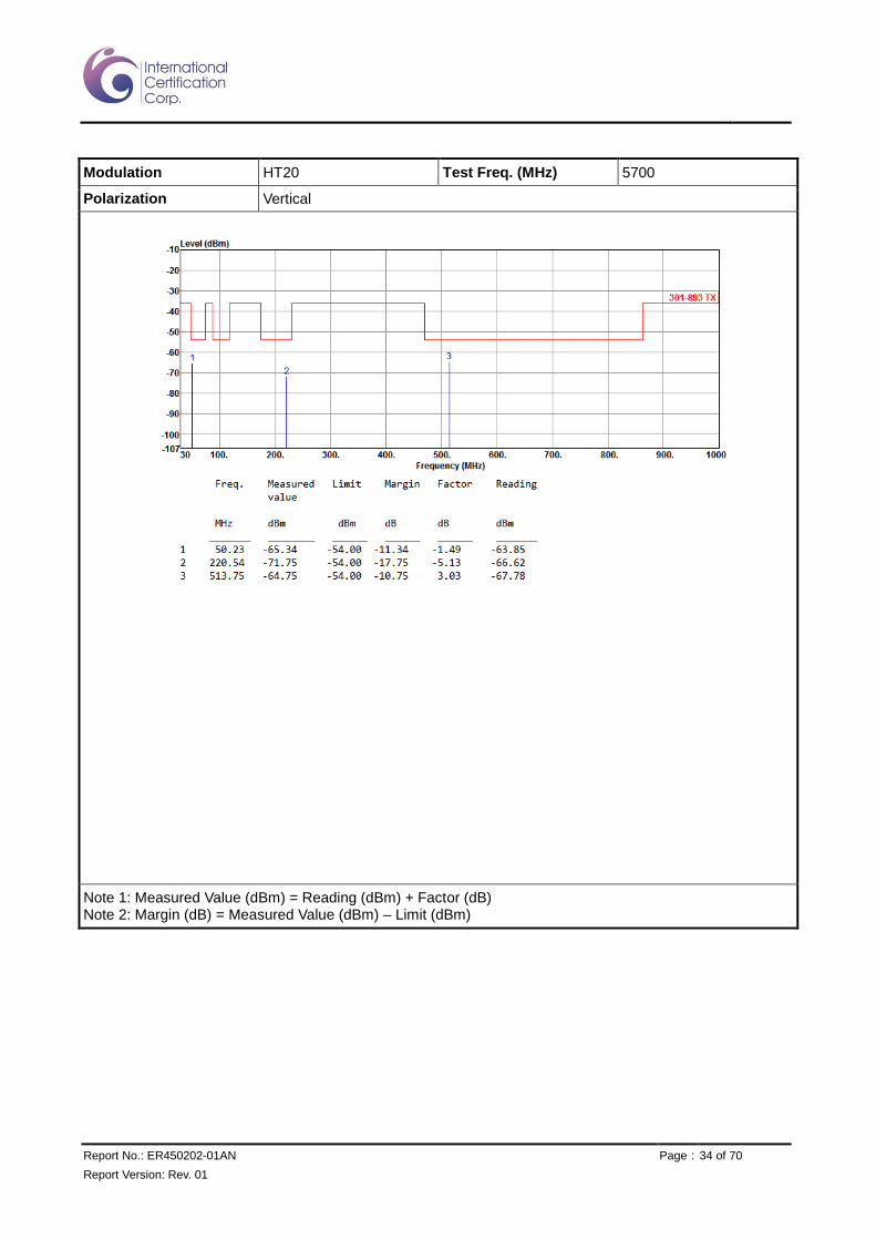
Modulation HT20 Test Freq. (MHz) 5700
Polarization Vertical
Note 1: Measured Value (dBm) = Reading (dBm) + Factor (dB) Note 2: Margin (dB) = Measured Value (dBm) – Limit (dBm)

Report No.: ER450202-01AN Page : 35 of 70
Report Version: Rev. 01
3.4.5 Transmitter Radiated Unwanted Emissions (Above 1GHz)
Modulation 11a Test Freq. (MHz) 5180
Polarization Horizontal
Note 1: Measured Value (dBm) = Reading (dBm) + Factor (dB) Note 2: Margin (dB) = Measured Value (dBm) – Limit (dBm)

Report No.: ER450202-01AN Page : 36 of 70
Report Version: Rev. 01
Modulation 11a Test Freq. (MHz) 5180
Polarization Vertical
Note 1: Measured Value (dBm) = Reading (dBm) + Factor (dB) Note 2: Margin (dB) = Measured Value (dBm) – Limit (dBm)

Report No.: ER450202-01AN Page : 37 of 70
Report Version: Rev. 01
Modulation 11a Test Freq. (MHz) 5700
Polarization Horizontal
Note 1: Measured Value (dBm) = Reading (dBm) + Factor (dB) Note 2: Margin (dB) = Measured Value (dBm) – Limit (dBm)

Report No.: ER450202-01AN Page : 38 of 70
Report Version: Rev. 01
Modulation 11a Test Freq. (MHz) 5700
Polarization Vertical
Note 1: Measured Value (dBm) = Reading (dBm) + Factor (dB) Note 2: Margin (dB) = Measured Value (dBm) – Limit (dBm)

Report No.: ER450202-01AN Page : 39 of 70
Report Version: Rev. 01
Modulation HT20 Test Freq. (MHz) 5180
Polarization Horizontal
Note 1: Measured Value (dBm) = Reading (dBm) + Factor (dB) Note 2: Margin (dB) = Measured Value (dBm) – Limit (dBm)

Report No.: ER450202-01AN Page : 40 of 70
Report Version: Rev. 01
Modulation HT20 Test Freq. (MHz) 5180
Polarization Vertical
Note 1: Measured Value (dBm) = Reading (dBm) + Factor (dB) Note 2: Margin (dB) = Measured Value (dBm) – Limit (dBm)

Report No.: ER450202-01AN Page : 41 of 70
Report Version: Rev. 01
Modulation HT20 Test Freq. (MHz) 5700
Polarization Horizontal
Note 1: Measured Value (dBm) = Reading (dBm) + Factor (dB) Note 2: Margin (dB) = Measured Value (dBm) – Limit (dBm)

Report No.: ER450202-01AN Page : 42 of 70
Report Version: Rev. 01
Modulation HT20 Test Freq. (MHz) 5700
Polarization Vertical
Note 1: Measured Value (dBm) = Reading (dBm) + Factor (dB) Note 2: Margin (dB) = Measured Value (dBm) – Limit (dBm)

Report No.: ER450202-01AN Page : 43 of 70
Report Version: Rev. 01
3.5 Transmitter Unwanted Emissions within the 5 GHz RLAN Band
3.5.1 Limit of Transmitter Unwanted Emissions within the 5 GHz RLAN Band
3.5.2 Test Procedures
Reference to clause 5.3.6.2 of ETSI EN 301 893 V1.8.1 (2015-03).
3.5.3 Test Setup

Report No.: ER450202-01AN Page : 44 of 70
Report Version: Rev. 01
3.5.4 Test Result of Transmitter Unwanted Emissions within the 5 GHz RLAN Band
for 11a
5180MHz
5320MHz
5500MHz
5700MHz

Report No.: ER450202-01AN Page : 45 of 70
Report Version: Rev. 01
3.5.5 Test Result of Transmitter Unwanted Emissions within the 5 GHz RLAN Band
for HT20
5180MHz
5320MHz
5500MHz
5700MHz

Report No.: ER450202-01AN Page : 46 of 70
Report Version: Rev. 01
4 Receiver Test Results
4.1 Receiver Spurious Emissions
4.1.1 Limit of Receiver Spurious Emissions
Frequency Range Maximum power Measurement bandwidth
30 MHz to 1 GHz -57 dBm 100kHz
1 GHz to 26 GHz -47 dBm 1MHz
4.1.2 Test Procedures
Reference to clause 5.3.7.2 of ETSI EN 301 893 V1.8.1 (2015-03).

Report No.: ER450202-01AN Page : 47 of 70
Report Version: Rev. 01
4.1.3 Test Setup
Below 1GHz
Above 1 GHz

Report No.: ER450202-01AN Page : 48 of 70
Report Version: Rev. 01
4.1.4 Receiver Spurious Emissions (Below 1GHz)
Modulation 11a Test Freq. (MHz) 5180
Polarization Horizontal
Note 1: Measured Value (dBm) = Reading (dBm) + Factor (dB) Note 2: Margin (dB) = Measured Value (dBm) – Limit (dBm)

Report No.: ER450202-01AN Page : 49 of 70
Report Version: Rev. 01
Modulation 11a Test Freq. (MHz) 5180
Polarization Vertical
Note 1: Measured Value (dBm) = Reading (dBm) + Factor (dB) Note 2: Margin (dB) = Measured Value (dBm) – Limit (dBm)

Report No.: ER450202-01AN Page : 50 of 70
Report Version: Rev. 01
Modulation 11a Test Freq. (MHz) 5700
Polarization Horizontal
Note 1: Measured Value (dBm) = Reading (dBm) + Factor (dB) Note 2: Margin (dB) = Measured Value (dBm) – Limit (dBm)
Report No.: ER450202-01AN Page : 51 of 70
Report Version: Rev. 01
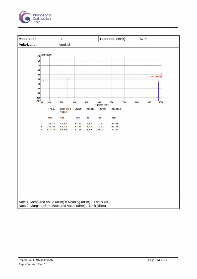
Modulation 11a Test Freq. (MHz) 5700
Polarization Vertical
Note 1: Measured Value (dBm) = Reading (dBm) + Factor (dB) Note 2: Margin (dB) = Measured Value (dBm) – Limit (dBm)

Report No.: ER450202-01AN Page : 52 of 70
Report Version: Rev. 01
Modulation HT20 Test Freq. (MHz) 5180
Polarization Horizontal
Note 1: Measured Value (dBm) = Reading (dBm) + Factor (dB) Note 2: Margin (dB) = Measured Value (dBm) – Limit (dBm)

Report No.: ER450202-01AN Page : 53 of 70
Report Version: Rev. 01
Modulation HT20 Test Freq. (MHz) 5180
Polarization Vertical
Note 1: Measured Value (dBm) = Reading (dBm) + Factor (dB) Note 2: Margin (dB) = Measured Value (dBm) – Limit (dBm)

Report No.: ER450202-01AN Page : 54 of 70
Report Version: Rev. 01
Modulation HT20 Test Freq. (MHz) 5700
Polarization Horizontal
Note 1: Measured Value (dBm) = Reading (dBm) + Factor (dB) Note 2: Margin (dB) = Measured Value (dBm) – Limit (dBm)
Report No.: ER450202-01AN Page : 55 of 70
Report Version: Rev. 01
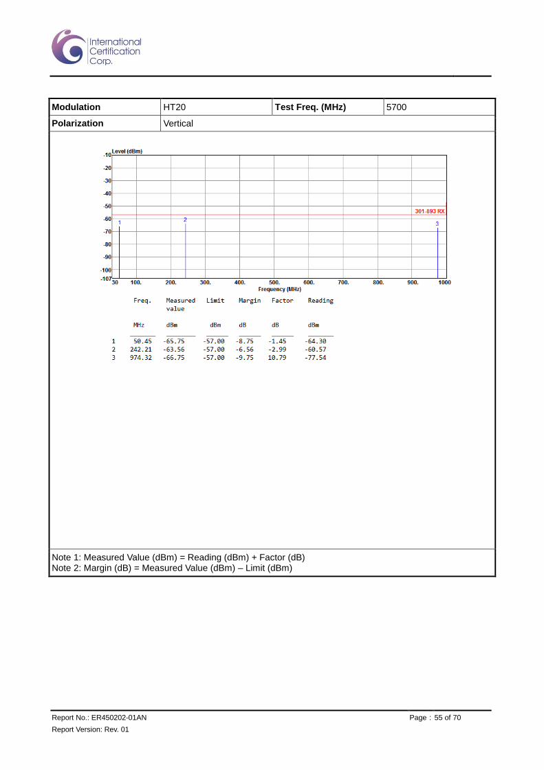
Modulation HT20 Test Freq. (MHz) 5700
Polarization Vertical
Note 1: Measured Value (dBm) = Reading (dBm) + Factor (dB) Note 2: Margin (dB) = Measured Value (dBm) – Limit (dBm)

Report No.: ER450202-01AN Page : 56 of 70
Report Version: Rev. 01
4.1.5 Receiver Spurious Emissions (Above 1GHz)
Modulation 11a Test Freq. (MHz) 5180
Polarization Horizontal
Note 1: Measured Value (dBm) = Reading (dBm) + Factor (dB) Note 2: Margin (dB) = Measured Value (dBm) – Limit (dBm)

Report No.: ER450202-01AN Page : 57 of 70
Report Version: Rev. 01
Modulation 11a Test Freq. (MHz) 5180
Polarization Vertical
Note 1: Measured Value (dBm) = Reading (dBm) + Factor (dB) Note 2: Margin (dB) = Measured Value (dBm) – Limit (dBm)

Report No.: ER450202-01AN Page : 58 of 70
Report Version: Rev. 01
Modulation 11a Test Freq. (MHz) 5700
Polarization Horizontal
Note 1: Measured Value (dBm) = Reading (dBm) + Factor (dB) Note 2: Margin (dB) = Measured Value (dBm) – Limit (dBm)

Report No.: ER450202-01AN Page : 59 of 70
Report Version: Rev. 01
Modulation 11a Test Freq. (MHz) 5700
Polarization Vertical
Note 1: Measured Value (dBm) = Reading (dBm) + Factor (dB) Note 2: Margin (dB) = Measured Value (dBm) – Limit (dBm)

Report No.: ER450202-01AN Page : 60 of 70
Report Version: Rev. 01
Modulation HT20 Test Freq. (MHz) 5180
Polarization Horizontal
Note 1: Measured Value (dBm) = Reading (dBm) + Factor (dB) Note 2: Margin (dB) = Measured Value (dBm) – Limit (dBm)

Report No.: ER450202-01AN Page : 61 of 70
Report Version: Rev. 01
Modulation HT20 Test Freq. (MHz) 5180
Polarization Vertical
Note 1: Measured Value (dBm) = Reading (dBm) + Factor (dB) Note 2: Margin (dB) = Measured Value (dBm) – Limit (dBm)

Report No.: ER450202-01AN Page : 62 of 70
Report Version: Rev. 01
Modulation HT20 Test Freq. (MHz) 5700
Polarization Horizontal
Note 1: Measured Value (dBm) = Reading (dBm) + Factor (dB) Note 2: Margin (dB) = Measured Value (dBm) – Limit (dBm)

Report No.: ER450202-01AN Page : 63 of 70
Report Version: Rev. 01
Modulation HT20 Test Freq. (MHz) 5700
Polarization Vertical
Note 1: Measured Value (dBm) = Reading (dBm) + Factor (dB) Note 2: Margin (dB) = Measured Value (dBm) – Limit (dBm)

Report No.: ER450202-01AN Page : 64 of 70
Report Version: Rev. 01
5 Adaptivity Test Results
5.1 Adaptivity
5.1.1 Adaptivity Limit
Adaptivity Limit
LBT based Detect and Avoid (Frame Based Equipment): Clear Channel Assessment (CCA) time shall be not less than 20 us; Channel Occupancy Time (COT) shall be in the range 1 ms ~ 10 ms Minimum Idle Period shall be at least 5 % of Channel Occupancy Time
Load based Equipment may implement an LBT based spectrum sharing mechanism based on the Clear Channel Assessment (CCA) mode using "energy detect", as described in IEEE 802.11™-2012 [8], clause 9, clause 10, clause 18 and clause 20 or as described in IEEE 802.11ac™-2013 [9], clause 8, clause 9, clause 10 and clause 22
LBT based Detect and Avoid (Load Based Equipment): Option A
Clear Channel Assessment (CCA) time shall be not less than 20 us Extended CCA(q * observed slots)
observed slot: 18us (ECCA time slot)or Busy slot q=16~1024 / N=1~q
Channel Occupancy Time (COT) shall be less than 10 ms Idle Period is equal to CCA or ECCA
Option B Clear Channel Assessment (CCA) time shall be not less than 20 us Extended CCA: N*CCA
N:1~q randomly / q=4~32 ( q is selected by the manufacturer) Channel Occupancy Time (COT) (13/32*q )ms Idle Period is equal to CCA~CCA*N
Short Control Signalling Transmissions: Short Control Signalling Transmissions shall have a maximum duty cycle of 5 % within an
observation period of 50 ms.
5.1.2 Test Procedures
Reference to clause 5.3.9.2 of ETSI EN 301 893 V1.8.1 (2015-03).
5.1.3 Test Setup

Report No.: ER450202-01AN Page : 65 of 70
Report Version: Rev. 01
5.1.4 Test Result of Adaptivity and Short Control Signalling Transmissions
Adaptivity Result
EUT firmware / software version V3.4.4.1
Adaptivity Detection Threshold Level (dBm) -64.51
Modulation Mode Freq. (MHz)
Short Control
Signalling
Transmissions
(ms)
Channel
Occupancy
Time (ms)
Idle Period
Time (us) Adaptivity
802.11an (HT20) 5180 1.777 2.036 61 Pass
802.11an (HT20) 5500 2.238 2.029 58 Pass
Limit < 2.5 ms - > 20us N/A
Adaptivity Result Plots
802.11an (HT20) - 5180MHz
802.11an (HT20) - 5500MHz

Report No.: ER450202-01AN Page : 66 of 70
Report Version: Rev. 01
Short Control Signalling Transmissions Plots
802.11an (HT20) - 5180MHz
802.11an (HT20) - 5500MHz

Report No.: ER450202-01AN Page : 67 of 70
Report Version: Rev. 01
Channel Occupancy Time
802.11an (HT20) - 5180MHz
802.11an (HT20) - 5500MHz
Idle Period Time
802.11an (HT20) - 5180MHz
802.11an (HT20) - 5500MHz

Report No.: ER450202-01AN Page : 68 of 70
Report Version: Rev. 01
6 Photographs of the Test Configuration
Spurious Emission Test

Report No.: ER450202-01AN Page : 69 of 70
Report Version: Rev. 01
Adaptivity and Short Control Signalling Transmissions Test

Report No.: ER450202-01AN Page : 70 of 70
Report Version: Rev. 01
7 Test laboratory information
Established in 2012, ICC provides foremost EMC & RF Testing and advisory consultation services by our
skilled engineers and technicians. Our services employ a wide variety of advanced edge test equipment and
one of the widest certification extents in the business.
International Certification Corp, it is our definitive objective is to institute long term, trust-based associations
with our clients. The expectation we set up with our clients is based on outstanding service, practical expertise
and devotion to a certified value structure. Our passion is to grant our clients with best EMC / RF services by
oriented knowledgeable and accommodating staff.
Our Test sites are located at Linkou District and Kwei Shan Hsiang. Location map can be found on our
website http://www.icertifi.com.tw.
Linkou Kwei Shan Kwei Shan Site II
Tel: 886-2-2601-1640 Tel: 886-3-271-8666 Tel: 886-3-271-8640
No. 30-2, Ding Fwu Tsuen, Lin Kou District, New Taipei City, Taiwan, R.O.C.
No. 3-1, Lane 6, Wen San 3rd St., Kwei Shan Hsiang, Tao Yuan Hsien 333, Taiwan, R.O.C.
No. 14-1, Lane 19, Wen San 3rd St., Kwei Shan Hsiang, Tao Yuan Hsien 333, Taiwan, R.O.C.
If you have any suggestion, please feel free to contact us as below information
Tel: 886-3-271-8666
Fax: 886-3-318-0155
Email: [email protected]
══END══