Embed Size (px)
Citation preview

Pocket Laser Tach 200(PLT200)
Tachometer / Rate Meter / Totalizer / Timer
MONARCH INSTRUMENT Instruction Manual
15 Columbia DriveAmherst, NH 03031-2334 USAPhone: (603) 883-3390Fax: (603) 886-3300E-mail: [email protected]: www.monarchinstrument.com
Printed in the U.S.A.Copyright 2004 Monarch Instrument, all rights reserved
1071-4838-112
CE DECLARATION OF CONFORMITY
As Manufacturer:
Monarch InstrumentDivision of Monarch International Inc.
15 Columbia Drive, Amherst NH 03031 USAdeclares under Monarch’s sole responsibility that the product:
to which this declaration relates is in conformity with the following directives andstandards when installed and operated in accordance with the user manual:
References: Retlif Testing Laboratories, (Report No. R-4283N)Technical Construction File PLT-0704 of July 2004
Pocket Laser Tach 200
24th June 2004Manufacturer (Amherst,NH) Alan Woolfson, VP Engineering (Authorized Signature)
Directives: EMC 89/336/EEC
Standards: EMC: EN61326:1997Electrical Safety: IEC61010-1:2001Laser Safety: IEC60825-1:2001
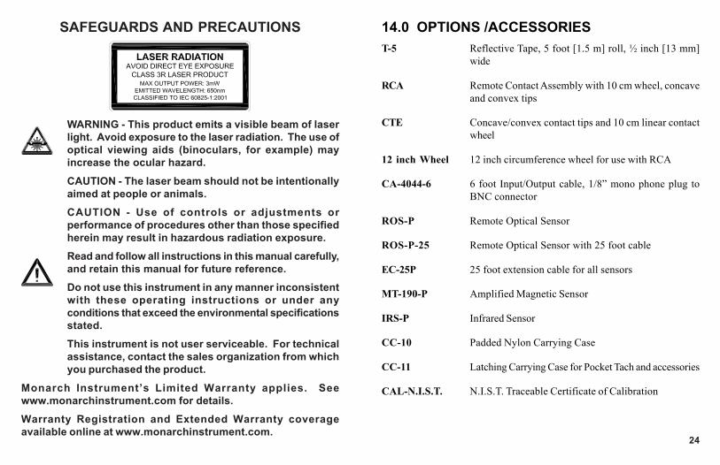
SAFEGUARDS AND PRECAUTIONS
WARNING - This product emits a visible beam of laserlight. Avoid exposure to the laser radiation. The use ofoptical viewing aids (binoculars, for example) mayincrease the ocular hazard.
CAUTION - The laser beam should not be intentionallyaimed at people or animals.
CAUTION - Use of controls or adjustments orperformance of procedures other than those specifiedherein may result in hazardous radiation exposure.
Read and follow all instructions in this manual carefully,and retain this manual for future reference.
Do not use this instrument in any manner inconsistentwith these operating instructions or under anyconditions that exceed the environmental specificationsstated.
This instrument is not user serviceable. For technicalassistance, contact the sales organization from whichyou purchased the product.
Monarch Instrument’s Limited Warranty applies. Seewww.monarchinstrument.com for details.
Warranty Registration and Extended Warranty coverageavailable online at www.monarchinstrument.com.
24
14.0 OPTIONS /ACCESSORIEST-5 Reflective Tape, 5 foot [1.5 m] roll, ½ inch [13 mm]
wide
RCA Remote Contact Assembly with 10 cm wheel, concaveand convex tips
CTE Concave/convex contact tips and 10 cm linear contactwheel
12 inch Wheel 12 inch circumference wheel for use with RCA
CA-4044-6 6 foot Input/Output cable, 1/8” mono phone plug toBNC connector
ROS-P Remote Optical Sensor
ROS-P-25 Remote Optical Sensor with 25 foot cable
EC-25P 25 foot extension cable for all sensors
MT-190-P Amplified Magnetic Sensor
IRS-P Infrared Sensor
CC-10 Padded Nylon Carrying Case
CC-11 Latching Carrying Case for Pocket Tach and accessories
CAL-N.I.S.T. N.I.S.T. Traceable Certificate of Calibration

TABLE OF CONTENTSTABLE OF CONTENTS
1.0 OVERVIEW ............................................................................. 12.0 FEATURE LOCATIONS ............................................................ 13.0 LCD DISPLAY SYMBOLS ....................................................... 24.0 PLT200 SPECIFICATIONS ...................................................... 35.0 PREPARATION FOR MEASUREMENT .................................... 7
5.1 Non-Contact Preparation ............................................. 75.2 Direct Contact Preparation.......................................... 75.3 Connecting External Sensors ..................................... 8
6.0 TACHometer Mode ................................................................ 96.1 TACHometer Setup ....................................................... 96.2 TACHometer Operation .............................................. 11
7.0 RATE Mode........................................................................... 127.1 RATE Setup ................................................................. 127.2 RATE Operation .......................................................... 14
8.0 TOTALizer Mode .................................................................. 158.1 TOTALizer Setup ......................................................... 158.2 TOTALizer Operation .................................................. 18
9.0 TIMER Mode ......................................................................... 199.1 TIMER Setup................................................................ 199.2 TIMER Operation ......................................................... 20
10.0 MAKING MEASUREMENTS .................................................. 2110.1 Non-Contact Measurements ..................................... 2110.2 Direct Contact Measurements .................................. 21
11.0 INPUT / OUTPUT .................................................................. 2212.0 BATTERIES ........................................................................... 2313.0 CLEANING ............................................................................ 2314.0 OPTIONS /ACCESSORIES ................................................... 24
23
When displayed, replace batteries.
Remove batterycover
Install two 1.5V“AA” alkalinebatteries
NOTE: Bothbatteries face thesame direction.
12.0 BATTERIES
13.0 CLEANINGTo clean the instrument, wipe with a damp cloth using mild soapy solution.

1
1.0OVERVIEWThe Pocket Laser Tach 200 is a precision hand-held multifunctionTachometer, Ratemeter, Totalizer and Timer. It is programmable to displaydirectly in Revs, Inches, Feet, Yards, Miles, Centimeters and Meters orfunction as a stopwatch or interval timer. Input / output sockets allow forremote sensing and pulse output to external indicating devices. For ease ofuse, the instrument can be “Locked-on” for continuous operation.
2.0FEATURE LOCATIONS
Min / ScrollDown arrow
Start / Reset button
Max / Scroll Uparrow
LCD display
Menu / Selectand Lock-onbutton
Battery compartment
AVOID EXPOSURE - LASER RADIATION ISEMITTED FROM THIS APERTURE
Output socketInput socket
Belt clip
Tripod mounting bushing(underside)
22
Output socket ( )Input socket ( )
Input: Accepts remote sensor orRemote Contact Assembly(RCA). 1/8” (3.5mm) stereophone plug.
Output: 1 pulse per revolution TTLoutput on internal operation.Pulse repeater with externalsensors. 1/8” (3.5mm) monophone plug.
Signal Input
Common(GND)
Common(GND)
Signal Input
Signal Input
+3V Out toSensor
Common(GND)
Common(GND)+3V Out toSensor
Signal Input
Input Connector Detail (Stereo plug)
Output Connector Detail (Mono plug)
11.0 INPUT / OUTPUT

2
3.0LCD DISPLAY SYMBOLS
On Target Indicator. Blinks on whenever there is an inputsignal. Will appear to be solid on at higher frequencies.
Low Battery icon. Indicates that the batteries are low andneed to be replaced.
Times Ten icon. Indicates that the value shown is ten timesthat which is displayed.
Laser Indicator. Red laser is on when this indicator isilluminated.
Lock icon. Indicates that the unit is “Locked” on and makingcontinuous measurements (Lock mode).
Hand-held
21
10.0 MAKING MEASUREMENTS10.1 Non-Contact Measurements
10.2 Direct Contact Measurements
Laser
External Sensor (ROS shown)OR
Light
WARNING: Making measurements in direct contact with rotatingequipment can be dangerous. Keep all loose clothing and hairaway from exposed moving machinery. Keep the hand holdingthe instrument well behind the back end of the Remote ContactAssembly. Properly replace all machinery guards after completingmeasurement. Do not use for rotation greater than 20,000 RPM.
to RCA
from PLT200 from PLT200
Rotational Linear
(Use concavetip for smallshafts)
ONLY USE MODERATE PRESSURE
(Not shown:IRS-P,
MT-190P)
3
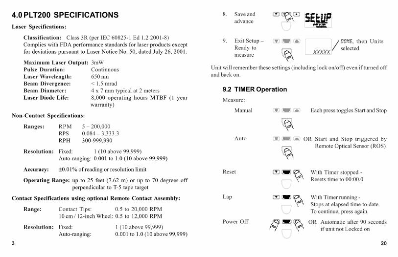
4.0PLT200 SPECIFICATIONSLaser Specifications:
Classification: Class 3R (per IEC 60825-1 Ed 1.2 2001-8)Complies with FDA performance standards for laser products exceptfor deviations pursuant to Laser Notice No. 50, dated July 26, 2001.
Maximum Laser Output: 3mWPulse Duration: ContinuousLaser Wavelength: 650 nmBeam Divergence: < 1.5 mradBeam Diameter: 4 x 7 mm typical at 2 metersLaser Diode Life: 8,000 operating hours MTBF (1 year
warranty)
Non-Contact Specifications:
Ranges: RPM 5 – 200,000RPS 0.084 – 3,333.3RPH 300-999,990
Resolution: Fixed: 1 (10 above 99,999)Auto-ranging: 0.001 to 1.0 (10 above 99,999)
Accuracy: ±0.01% of reading or resolution limit
Operating Range: up to 25 feet (7.62 m) or up to 70 degrees offperpendicular to T-5 tape target
Contact Specifications using optional Remote Contact Assembly:
Range: Contact Tips: 0.5 to 20,000 RPM10 cm / 12-inch Wheel: 0.5 to 12,000 RPM
Resolution: Fixed: 1 (10 above 99,999)Auto-ranging: 0.001 to 1.0 (10 above 99,999)
20
8. Save andadvance
9. Exit Setup –Ready tomeasure
Measure:
Reset
Lap
Power Off
Unit will remember these settings (including lock on/off) even if turned offand back on.
DONE, then Unitsselected
Manual
Auto
Each press toggles Start and Stop
Start and Stop triggered byRemote Optical Sensor (ROS)
With Timer stopped -Resets time to 00:00.0
With Timer running -Stops at elapsed time to date.To continue, press again.
OR
9.2 TIMER Operation
Automatic after 90 secondsif unit not Locked on
OR

4
Contact Specifications (continued):
Accuracy: Revs: ±0.05% of reading (RPM) or resolution limit(with no slippage)
Linear: ±0.5% of reading or resolution limit (with noslippage)
Contact Measurements Ranges:TACHOMETER:
Revolutions per Minute (RPM) 0.5 to 20,000 RPMRevolutions per Second (RPS) 0.0833 to 333.33 RPSRevolution per Hour (RPH) 30 to 999,990 RPH
RATES: Wheel Circumference:Inches per Second 10 cm: 0.033 to 1312.3 IPS
12 in: 0.100 to 2,400.0 IPS
Inches per Minute 10 cm: 1.969 to 78,740 IPM12 in: 6.000 to 144,000 IPM
Inches per Hour 10 cm: 118.11 to 999,990 IPH12 in: 360.00 to 999,990 IPH
Feet per Second 10 cm: 0.003 to 109.36 FT/S12 in: 0.009 to 200.00 FT/S
Feet per Minute 10 cm: 0.164 to 6,561.7 FT/M12 in: 0.500 to 12,000 FT/M
Feet per Hour 10 cm: 9.843 to 393,700 FT/H12 in: 30.000 to 720,000 FT/H
Yards per Second 10 cm: 0.001 to 36.453 YPS12 in: 0.003 to 66.667 YPS
Yards per Minute 10 cm: 0.055 to 2,187.2 YPM12 in: 0.167 to 4,000.0 YPM
19
1. Turn PowerON
2. Enter SetupMode
3. Enter selectionof Mode
4. Select TIMERMode
5. Save andadvance
6. Enter selectionof Timerfunction
7. Select Timerfunction
OR Repeat untilTIMER displayed
Last Mode selectedis displayed
1a. To toggle LockOn/Off
MAN or AUTO
Last Units selectedare displayed
Locked On
OR Toggles betweenManual andAuto
Press and Hold
9.0TIMER Mode9.1 TIMER Setup

5
Contact Measurements Ranges (continued):RATES: Wheel Circumference:
Yards per Hour 10cm: 3.281 to 131,233 YPH12 in: 10.000 to 240,000 YPH
Miles per Hour 10 cm: 0.002 to 74.564 MPH12 in: 0.006 to 136.36 MPH
Centimeters per Second 10 cm: 0.084 to 3,333.3 CM/S12 in: 0.21 to 3,048.0 CM/S
Centimeters per Minute 10 cm: 5.000 to 200,000 CM/M12 in: 15.240 to 365,760 CM/M
Centimeters per Hour 10 cm: 300.00 to 999,990 CM/H12 in: 914.40 to 999,990 CM/H
Meters per Second 10 cm: 0.001 to 33.333 M/SEC12 in: 0.003 to 60.960 M/SEC
Meters per Minute 10 cm: 0.050 to 2,000.0 M/MIN12 in: 0.153 to 3,657.6 M/MIN
Meters per Hour 10 cm: 3.000 to 120,000 M/H12 in: 9.144 to 219,460 M/H
TOTALIZER:Counts: 0 to 999,999Scale Totals in Inches, Feet, Yards, Centimeters or MetersInput: Internal or External optics or linear contact wheel
Timer Specifications:
Minutes:Seconds.Tenths to 99:59.9
Accuracy: ±0.2 second
Resolution: 0.1 second18
Measure
Recall Max
Recall Min
If unit isLocked on:
Power Off
Min Speed
Max Speed
OR
Press and hold Lock on
Resets Max/Min and Total
8.2 TOTALizer Operation
Automatic after 90 seconds ifunit not Locked on
OR

Display: 5 x 0.5” (12.7mm) numeric digits plus 5 Alpha-numeric LCD
Batteries: 2 “AA” 1.5 V (DC) alkaline included (Note: Batteries are NOT rechargeable.)
Battery Life: 30 hours continuous typical with batteries provided
External Input:
Absolute max: -0.3 V to 5 V (DC)
Minimum: low below 1.2 V and high above 2 V (TTL compatible)
Edge: Triggers on Positive edge
Power Out: 3.0 V nominal, approx. 2.8 V @ 20 mA max
Pulse Output: 0 V to 3.3 V (DC) pulseSame shape as External Input signal or high when internaloptics sees a reflection
Dimensions: 6.92” (17.58 cm) H x 2.4” (6.10 cm) W x 1.6” (4.06 cm) D
Weight: Approx. 7 oz. (210 g)
This product is designed to be safe for indoor use under the followingconditions (per IEC61010-1).
Installation Category II per IEC 664
Pollution Degree Level II per IEC 664
Temperature: 40 °F to 105 °F (5 °C to 40 °C)
Humidity: Maximum relative humidity of 80% for temperatures upto 88 °F (31 °C) decreasing linearly to 50% relativehumidity at 100 °F (40 °C). Humidity non-condensing.
Specifications subject to change without notice.617
TOTALizer Setup (continued):
NONE, 1, 2 or 3
OR Repeat untildesired decimalplaces displayed
Unit will remember these settings (including lock on/off) even if turned offand back on.
DONE,then Units selected
DONE,USE CONTACT TIP or[wheel selected],then Units selected
Units = COUNT: Rotational/Linear Units:
9. Enter selectionof number ofdecimal places
10. Select decimalplaces
11. Save andadvance
12. Exit Setup –Ready tomeasure

7
5.0PREPARATION FOR MEASUREMENT5.1 Non-Contact Preparation
For Internal operation (Red laser) or External operationusing optional Remote Optical Sensor (ROS-Red LED).
5.2 Direct Contact Preparation
For External operation ONLY using optional RemoteContact Assembly (RCA).
1. CleanShaft
As small as 1/8” wideon side or radius edge
2. Apply 1/2”square T-5Reflectivetape
For Small Shafts:
Select and install contact option:
1. Contact Tip (Convex tip shown.Use Concave tip for small shafts.)
Align flats
16
6. Enterselection ofUnits
7. Select Units
8. Save andadvance
Rotational: REVLinear: INCH, FEET,YARDS, CM, METER
Different options displayed forInternal or External operation.
Internal or External ROS: External RCA:COUNTOnly
OR Repeat untildesired Unitsdisplayed
COUNT or REV Linear Units
OR
8a. Enter selectionof Wheel
8b. Select Wheel
8c. Save andAdvance
Only for Linear Units:
OR Togglesbetween10CM and1 2 I N
Last Wheelselected isdisplayed

8
5.3 Connecting External Sensors
Plug sensor intoInput socket
Tighten screwsecurely into flaton shaft.
Remote OpticalSensor (ROS-P)
Install withpin in shaftfully seatedin slot.Tightenscrew.
2. 10 cm Wheel 3. 12 inch Wheel
OR
Remote ContactAssembly (RCA)
(shown with optional 12 inch wheel)
In
Infrared Sensor(IRS-P)
Magnetic Sensorwith Amplifier
(MT-190P)15
1. Turn PowerON
2. Enter SetupMode
3. Enterselection ofMode
4. SelectTOTALMode
5. Save andadvance
OR Repeat untilTOTAL displayed.
Last Mode selectedis displayed
1a. To toggle Lock On/Off
Different messages displayed forInternal or External operation.
Locked On
Internal or External ROS: External RCA:EXTRN, then scrollingmessage, then lastUnits selected
Last Unitsselected
Press and Hold
8.0TOTALizer Mode8.1 TOTALizer Setup

9
6.0TACHometer Mode6.1 TACHometer Setup
1. TurnPowerON
2. EnterSetupMode
3. Enterselectionof Mode
4. SelectTACHMode
5. Save andadvance
6. Enterselectionof Units
OR Repeat until TACHdisplayed
Last Mode selected isdisplayed
1a. To toggle LockOn/Off
RPS, RPM or RPH
Last Units selected aredisplayed
Locked OnPress and Hold
14
Unit will remember these settings (including lock on/off) even if turned offand back on.
DONE,USE CONTACT TIP or[wheel selected],then Units selected
Min Speed
Max Speed
OR
Press and hold Lock on
11. Save andadvance
12. Exit Setup –Ready tomeasure
Measure
Recall Max
Recall Min
If unit Lockedon:
Power Off
7.2 RATE Operation
Resets Max/Min
Automatic after 90 secondsif unit not Locked on
OR

NONE, 1, 2 or 3
OR Repeat untildesired decimalplaces displayed
Unit will remember these settings (including lock on/off) even if turned offand back on.
OR Repeat untildesired Unitsdisplayed
DONE, then Unitsselected
10
7. Select Units
8. Save andadvance
9. Enter selectionof number ofdecimal places
10. Select decimalplaces
11. Save andadvance
12. Exit Setup –Ready tomeasure
13
Rotational: C RPS,C RPM or C RPH
Linear: IPS, IPM, IPH, FT/S, FT/M, FT/H, YPS, YPM,YPH, MPH, CM/S, CM/M, CM/H, M/SEC, M/MIN, M/H
NONE, 1, 2 or 3
OR Repeat untildesired decimalplaces displayed
OR Repeat untildesired Unitsdisplayed
8a. Enterselection ofWheel
8b. SelectWheel
8c. Save andAdvance
Only for Linear Units:Rotational Units Linear Units
OR
OR Togglesbetween 10CMand 12IN
Last Wheelselected isdisplayed
6. Enter selectionof Units
7. Select Units
8. Save andadvance
9. Enter selectionof number ofdecimal places
10. Select decimalplaces
RATE Setup (continued):

11
Measure
Recall Max
Recall Min
If unit Lockedon:
Power OFF
Min Speed
Max Speed
Automatic after 90 secondsif unit not Locked on
OR
Press and hold Lock on
6.2 TACHometer Operation
Resets Max/Min
OR
12
1. TurnPowerON
2. EnterSetupMode
3. Enterselectionof Mode
4. SelectRATEMode
5. Save andadvance
OR Toggles betweenRATE and TOTAL.Select RATE.
Last Mode selected isdisplayed
1a. To toggle LockOn/Off
EXTRN, then scrollingmessage, then last Unitsselected
Locked On
7.0RATE ModeNOTE: External Remote Contact Assembly (RCA) must be inserted into
input socket.
7.1 RATE Setup
Press and Hold


![[VIETMATHS.com] Ky Thuat Tach So Hang](https://img.dokumen.tips/doc/110x75/55cf856b550346484b8dd68f/vietmathscom-ky-thuat-tach-so-hang.jpg)