Embed Size (px)
Citation preview

1 Precision Making Precision Making
Bill Gatheridge
Product Manager Yokogawa Corporation of America
Electric Motor And
Variable Speed Drive Testing

2 Precision Making
Kristina Neahr
Marketing Specialist Yokogawa Corporation of America
Newnan, GA [email protected] 1-800-888-6400 ext 5437 tmi.yokogawa.com
Host
Motor & Drive Testing Copyright © Yokogawa Electric Corporation

3 Precision Making
PC’s Speakers - Audio Broadcast To hear the audio through your PC, select the Communicate Tab and Join the Audio Broadcast.
Recorded Presentation A recording of this presentation will be posted under our technical library of our web page. Chat: Select and send all questions to “Panelist” during the Webinar presentation.
Yokogawa Webinar – Housekeeping Issues
Motor & Drive Testing Copyright © Yokogawa Electric Corporation

4 Precision Making
Bill Gatheridge Product Manager Yokogawa Corporation of America Newnan, GA 1-800-888-6400 Ext 5454 [email protected] tmi.yokogawa.com
Presenter
Motor & Drive Testing Copyright © Yokogawa Electric Corporation

5 Precision Making
Providing Solu-ons and
Educa-on for
Electrical Power Measurements
Motor & Drive Testing Copyright © Yokogawa Electric Corporation

6 Precision Making
If you have any questions for one of these Webinar Topics, please send them to the below e-mail. I will try to answer them during the Webinar or directly afterwards.
Questions
Motor & Drive Testing Copyright © Yokogawa Electric Corporation

7 Precision Making
• Founded in 1915. • First to produce and sell electric
meters in Japan. • North American operation established
in 1957 • World wide sales in excess of $4.3 B • 84 companies world wide • Over 20,000 employees worldwide • Operations in 33 Countries
1930 Vintage Standard AC Voltmeter 0.2% Accuracy Class
WT3000E Precision Power Analyzer
Harmonic Analysis Copyright © Yokogawa Electric Corporation
Yokogawa Corporate History

8 Precision Making
Yokogawa Corporation of America Newnan, GA
Yokogawa Corporation of America
Motor & Drive Testing Copyright © Yokogawa Electric Corporation

9 Precision Making
Yokogawa Corporation of America
Motor & Drive Testing Copyright © Yokogawa Electric Corporation

10 Precision Making
Electric Motor and
Variable Speed Drive Testing
Todays Topic
Motor & Drive Testing Copyright © Yokogawa Electric Corporation

11 Precision Making
11
u Provide you with a Three Step Process for a Complete Electrical Test of an AC Motor & Variable Speed Drive System
Objec&ve
Speed and Torque Meter
Load Motor DC or Single Phase or Three Phase AC Input
Inverter
Objective
Motor & Drive Testing Copyright © Yokogawa Electric Corporation
12 Precision Making
12
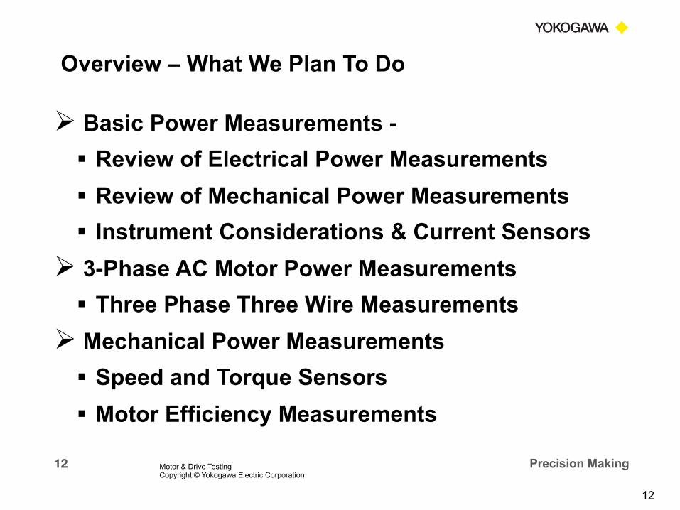
Ø Basic Power Measurements - § Review of Electrical Power Measurements § Review of Mechanical Power Measurements § Instrument Considerations & Current Sensors
Ø 3-Phase AC Motor Power Measurements § Three Phase Three Wire Measurements
Ø Mechanical Power Measurements § Speed and Torque Sensors § Motor Efficiency Measurements
Overview – What We Plan To Do
Motor & Drive Testing Copyright © Yokogawa Electric Corporation

13 Precision Making
Ø PWM Motor Drive Measurements § Input & Output Electrical Measurements § Drive Power Loss & Efficiency § Other Typical Drive Measurements
Ø Motor and Drive System Measurements § Putting it All Together § Total System Measurements & Efficiency § IEEE Std 112 Testing
Ø Answer YOUR Power and Motor Measurement Questions
Motor & Drive Testing Copyright © Yokogawa Electric Corporation
Overview – What We Plan To Do

14 Precision Making 7/27/15
PART 1 BASIC ELECTRICAL POWER
MEASUREMENTS
Motor & Drive Testing Copyright © Yokogawa Electric Corporation

15 Precision Making
Review OHM’S LAW
Motor & Drive Testing Copyright © Yokogawa Electric Corporation

16 Precision Making
Average, RMS, Peak-to-Peak Value Conversion for Sinusoidal Wave
(multiplication factor to find)
Known Value Average RMS Peak Peak-to-Peak Average 1.0 1.11 1.57 3.14
RMS 0.9 1.0 1.414 2.828 Peak 0.637 0.707 1.0 2.0
Peak-to-Peak 0.32 0.3535 0.5 1.0
Average and RMS Values
Motor & Drive Testing Copyright © Yokogawa Electric Corporation

17 Precision Making
Average and RMS Values
Motor & Drive Testing Copyright © Yokogawa Electric Corporation
18 Precision Making
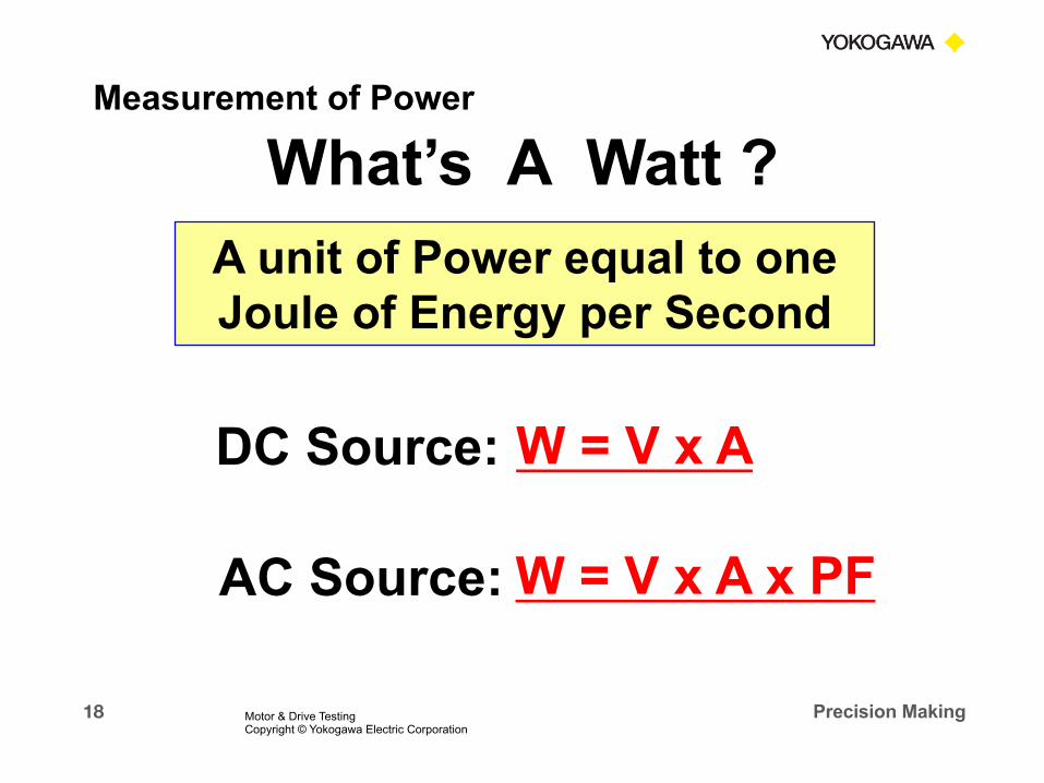
What’s A Watt ?
DC Source:
AC Source:
W = V x A
W = V x A x PF
A unit of Power equal to one Joule of Energy per Second
Measurement of Power
Motor & Drive Testing Copyright © Yokogawa Electric Corporation

19 Precision Making
AC Power Measurement
n Active Power:
Watts P = Vrms x Arms x PF
§ Also sometimes referred to as True Power or Real Power
n Apparent Power: Volt-Amps S = Vrms x Arms
Measurement of Power
Motor & Drive Testing Copyright © Yokogawa Electric Corporation
20 Precision Making
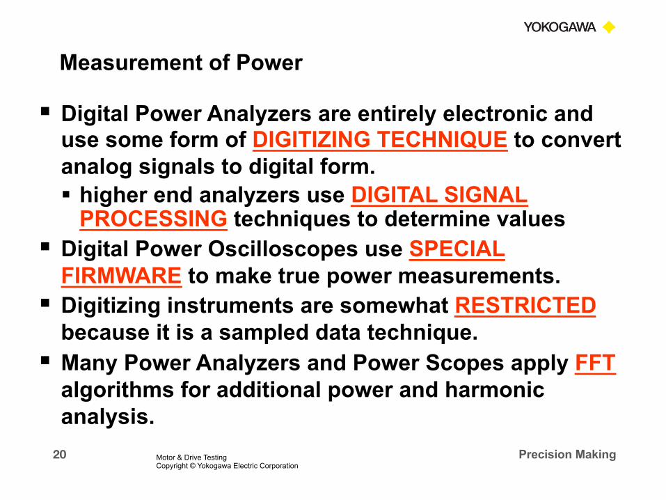
§ Digital Power Analyzers are entirely electronic and use some form of DIGITIZING TECHNIQUE to convert analog signals to digital form. § higher end analyzers use DIGITAL SIGNAL
PROCESSING techniques to determine values § Digital Power Oscilloscopes use SPECIAL
FIRMWARE to make true power measurements. § Digitizing instruments are somewhat RESTRICTED
because it is a sampled data technique. § Many Power Analyzers and Power Scopes apply FFT
algorithms for additional power and harmonic analysis.
Measurement of Power
Motor & Drive Testing Copyright © Yokogawa Electric Corporation

21 Precision Making
§ Yokogawa Digital Power Analyzers and Digital Power Scopes use the following method to calculate power:
§ Using digitizing techniques, the INSTANTANEOUS VOLTAGE is multiplied by the INSTANTANEOUS CURRENT and then INTEGRATED over some time period.
T Pavg = 1/T ∫0 v(t) * I (t) dt
Measurement of Power
Motor & Drive Testing Copyright © Yokogawa Electric Corporation

22 Precision Making
Watts P = Vrms x Arms x PF = Urms1 x Irms1 x λ1
Volt-Amps S = Vrms x Arms = Urms1 x Irms1
Measurement of AC Power
Motor & Drive Testing Copyright © Yokogawa Electric Corporation

23 Precision Making
These calculation methods provide a True Power Measurement and True RMS Measurement on any type of waveform, including all the harmonic content, up to the bandwidth of the instrument.
T
URMS = √1/T ∫0 v(t)2 dt
Ptotal = 1/T ∫0 v(t) * I (t) dt
T
T IRMS = √1/T ∫0 i(t)2 dt
True RMS Measurements
Motor & Drive Testing Copyright © Yokogawa Electric Corporation
24 Precision Making
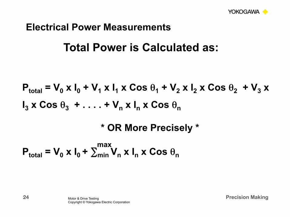
Total Power is Calculated as:
Ptotal = V0 x I0 + V1 x I1 x Cos θ1 + V2 x I2 x Cos θ2 + V3 x
I3 x Cos θ3 + . . . . + Vn x In x Cos θn
* OR More Precisely *
Ptotal = V0 x I0 + ∑min Vn x In x Cos θn max
Electrical Power Measurements
Motor & Drive Testing Copyright © Yokogawa Electric Corporation

25 Precision Making
Blondel’s Theory states that Total Power is measured with ONE LESS Wattmeter than the number of WIRES.
1-P 2-W 1 Wattmeter
1-P 3-W 2 Wattmeters 3-P 3-W 2 Wattmeters
3-P 4-W 3 Wattmeters
Blondel Transformation Electrical Power Measurements
Motor & Drive Testing Copyright © Yokogawa Electric Corporation

26 Precision Making
AC Source
a
b
c
vac
vcb
vab Three - Wire
Three - Phase Load
Wa
Wb
Wc
A
A
A
V
V
+
V+
+
+
+
+
Two Wattmeter Method
PT = ∑ Wa + Wb Motor & Drive Testing Copyright © Yokogawa Electric Corporation
Three - Phase Three - Wire System With Two Meters
Electrical Power Measurements

27 Precision Making
Advantages of Two-Wattmeter System
n Simple installation and wiring configuration
n Accurate Power measurement on balanced or unbalanced system
n Lower cost installation requiring only two Current and Potential Transformers
n Good system for production testing
Electrical Power Measurements
Motor & Drive Testing Copyright © Yokogawa Electric Corporation

28 Precision Making
a
b
c
vab
vbc
vca Three - Phase Three - Wire Load
Wa
Wb
Wc
. .
.
A
A
A
AC Source
V
V
+ -
V
- +
. Three-Phase Three-Wire System With Three Meters
BEST Method for Engineering and R&D Work
Three Watt Meter Method
Electrical Power Measurements
Motor & Drive Testing Copyright © Yokogawa Electric Corporation
29 Precision Making
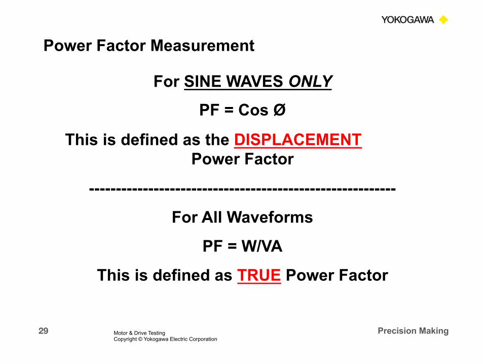
For SINE WAVES ONLY
PF = Cos Ø
This is defined as the DISPLACEMENT Power Factor
---------------------------------------------------------
For All Waveforms
PF = W/VA
This is defined as TRUE Power Factor
Power Factor Measurement
Motor & Drive Testing Copyright © Yokogawa Electric Corporation

30 Precision Making
3-Phase 4-Wire System
PFTotal = ∑ W / ∑ VA
PFTotal = ( W1 + W2 + W3 ) / ( VA1 + VA2 + VA3 )
Power Factor on 3-Phase System
Motor & Drive Testing Copyright © Yokogawa Electric Corporation
31 Precision Making
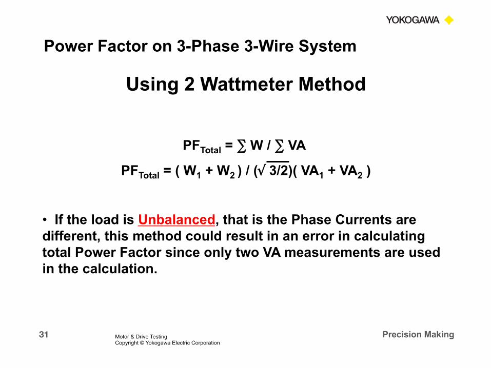
Using 2 Wattmeter Method
PFTotal = ∑ W / ∑ VA
PFTotal = ( W1 + W2 ) / (√ 3/2)( VA1 + VA2 )
• If the load is Unbalanced, that is the Phase Currents are different, this method could result in an error in calculating total Power Factor since only two VA measurements are used in the calculation.
Power Factor on 3-Phase 3-Wire System
Motor & Drive Testing Copyright © Yokogawa Electric Corporation

32 Precision Making
Using 3 Wattmeter Method
PFTotal = ∑ W / ∑ VA
PFTotal = ( W1 + W2 ) / (√ 3/3)( VA1 + VA2 + VA3 )
• This method will give correct Power Factor calculation on either Balanced or Unbalanced 3-Wire system. Note that all three VA measurements are used in the calculation. This calculation is performed in the Yokogawa Power Analyzers when using the 3V-3A wiring method.
Power Factor on 3-Phase 3-Wire System
Motor & Drive Testing Copyright © Yokogawa Electric Corporation
33 Precision Making
§ With the Yokogawa Power Analyzers, on a 3-Phase 3-Wire System, use the 3V-3A wiring method. This method will give correct Total Power, Total Power Factor and VA Measurements on either Balanced or Unbalanced 3-Wire system.
Power Factor on 3-Phase 3-Wire System
Motor & Drive Testing Copyright © Yokogawa Electric Corporation

34 Precision Making 7/27/15
PART 2
Basic MECHANICAL
Power Measurements
Motor & Drive Testing Copyright © Yokogawa Electric Corporation

35 Precision Making
§ In an Electric Motor: Pm = Speed x Torque
§ Mechanical Power is typically defined as Kilowatts or Horsepower
§ 1 Watt = Joule/Sec = Newton-Meter/Sec
Motor & Drive Testing Copyright © Yokogawa Electric Corporation
Mechanical Power Measurements

36 Precision Making
Pm =
2 x π x Rotating Speed
60 x Torque
Rotating Speed = RPM
Torque = N-m
Pm = Mechanical Power in Watts
Motor & Drive Testing Copyright © Yokogawa Electric Corporation
Mechanical Power Measurements

37 Precision Making
HP = Work done per unit of time. 1 HP = 33,000 lb-ft of work per minute. HP = 1 HP = 745.69987 W > 745.7 W > 746 W
RPM x Torque (lb-ft)
5,252
Motor & Drive Testing Copyright © Yokogawa Electric Corporation
Mechanical Power Measurements

38 Precision Making
AC Induction Motor Speed: § Actual Speed – The Speed at which the Shaft rotates. Typically
measured with a Tachometer.
§ Synchronous Speed – The Speed of the Stator’s Magnetic Field Rotation. This is the motor’s theoretical speed since the rotor will always turn at a slightly slower rate.
Synchronous Speed =
Mechanical Power Measurements
120 x Frequency
Number of Poles
Motor & Drive Testing Copyright © Yokogawa Electric Corporation
Mechanical Power Measurements

39 Precision Making
§ Slip – The difference in the speed of the Rotor (RS) and the Synchronous Speed (SS).
% Slip =
Mechanical Power Measurements
SS - RS SS
Motor & Drive Testing Copyright © Yokogawa Electric Corporation
Mechanical Power Measurements

40 Precision Making
Efficiency, in a Basic Simple form, can be calculated as the ratio of Output Power to Total Input power.
Eff =
Output Power
Input Power
Pm
Electrical Input Power
=
Motor & Drive Testing Copyright © Yokogawa Electric Corporation
Mechanical Power Measurements

41 Precision Making 7/27/15
PART 3 Instrument Selection
Motor & Drive Testing Copyright © Yokogawa Electric Corporation

42 Precision Making
IEEE 112 2004 NVLAP 150 CSA C390
Input Power +/- 0.2% of FS +/- 0.2% of FS +/- 0.5% of Reading (includes CT & PT errors)
Voltage and Current +/- 0.2% of FS +/- 0.2% of FS +/- 0.5% of Reading (includes CT & PT errors)
CT's and PT's +/- 0.3% of FS (total ratio and phase)
+/- 0.3% of FS (total ratio and phase)
Torque +/- 0.2% of FS +/- 0.2% of FS 0.7% of Reading
Supply Frequency +/- 0.2% of FS +/- 0.2% of FS +/- 0.5% of Reading
Motor Speed (RPM) +/- 1 RPM +/- 1 RPM +/- 1 RPM
Temperature +/- 0.2% of FS +/- 0.2% of FS +/- 1.5 deg. C
Winding Resistance +/- 0.2% of FS +/- 0.2% of FS +/- 1% of Reading Motor & Drive Testing Copyright © Yokogawa Electric Corporation
North American Motor Testing Standards

43 Precision Making
Ram Meter Shunts
Yokogawa CT’s
Yokogawa/LEM (Danfysik) CT System 0.05%
Yokogawa Scope Probes
Pearson Electronics
Current Sensors
Motor & Drive Testing Copyright © Yokogawa Electric Corporation
AEMC 0.3% - 0.5% AC
1.5% - 3% AC/DC
1% - 2%
0.2%
1% 0.1%
0.33%
44 Precision Making
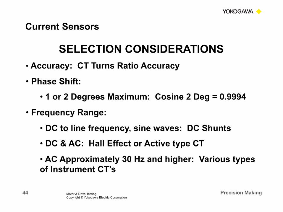
SELECTION CONSIDERATIONS
• Accuracy: CT Turns Ratio Accuracy
• Phase Shift:
• 1 or 2 Degrees Maximum: Cosine 2 Deg = 0.9994
• Frequency Range:
• DC to line frequency, sine waves: DC Shunts
• DC & AC: Hall Effect or Active type CT
• AC Approximately 30 Hz and higher: Various types of Instrument CT’s
Current Sensors
Motor & Drive Testing Copyright © Yokogawa Electric Corporation

45 Precision Making
SELECTION CONSIDERATIONS
• Instrument Compatibility:
• Output: Millivolts/Amp, Milliamps/Amp; or Amps
• Impedance and Load, Burden
• Scope Probes - - CAUTION! Use on Scopes, NOT Power Analyzers. Check the Specs!
• Physical Requirements:
• Size
• Connections: Clamp-On or Donut type
• Distance from Load to Instrument
Current Sensors
Motor & Drive Testing Copyright © Yokogawa Electric Corporation

46 Precision Making
A WORD OF CAUTION
Ø NEVER Open Circuit the Secondary side of a Current Transformer while it is energized!
• This could cause serious damage to the CT and could possibly be harmful to equipment operators.
• A CT is a Current Source.
• By Ohm’s Law E = I x R
• When R is very large, E becomes very high
• The High Voltage generated inside the CT will cause a magnetic saturation of the core, winding damage, or other damage which could destroy the CT.
Current Sensors
Motor & Drive Testing Copyright © Yokogawa Electric Corporation

47 Precision Making 7/27/15
PART 4 Electrical Power Measurements
On a 3 – Phase AC Motor
Motor & Drive Testing Copyright © Yokogawa Electric Corporation
48 Precision Making
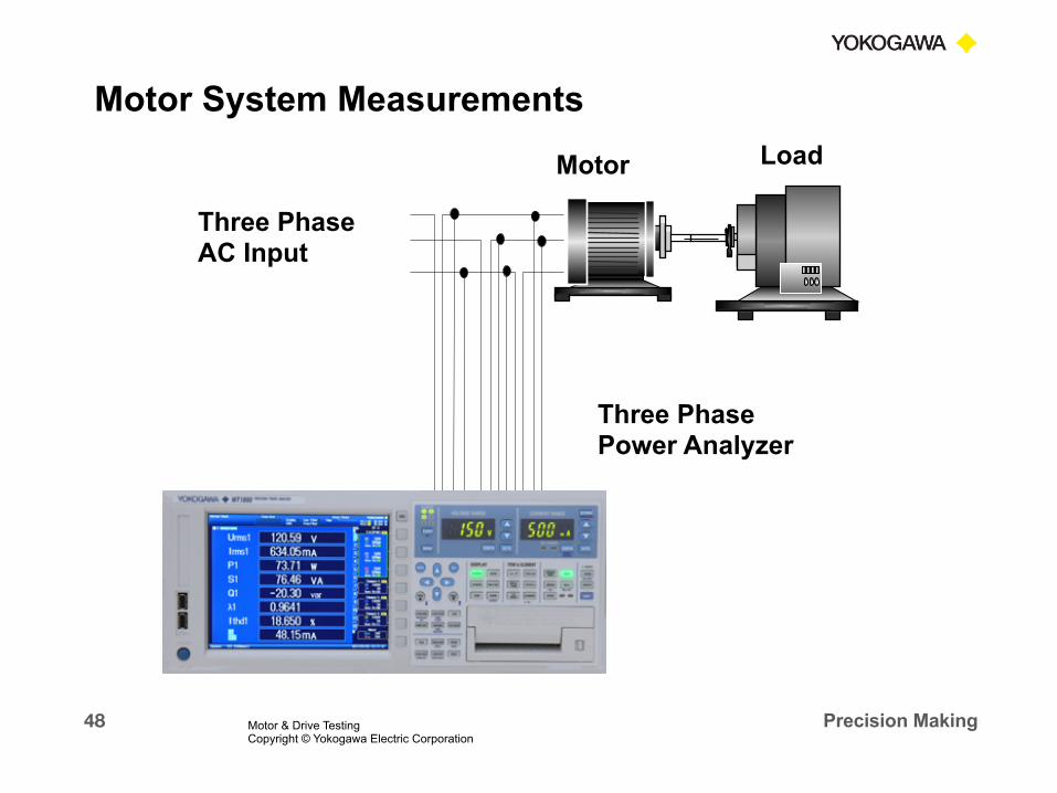
Three-Phase AC Motor
Load Motor
Three Phase AC Input
Three Phase Power Analyzer
Motor System Measurements
Motor & Drive Testing Copyright © Yokogawa Electric Corporation

49 Precision Making Motor & Drive Testing Copyright © Yokogawa Electric Corporation
Typical Power Measurements

50 Precision Making
Note that the Voltage Waveforms are 60 Degrees apart. The Current Waveforms are 120 Degrees apart.
Three-Phase Three-Wire “Delta” Connection
L-L Voltage
Phase Current
Motor & Drive Testing Copyright © Yokogawa Electric Corporation
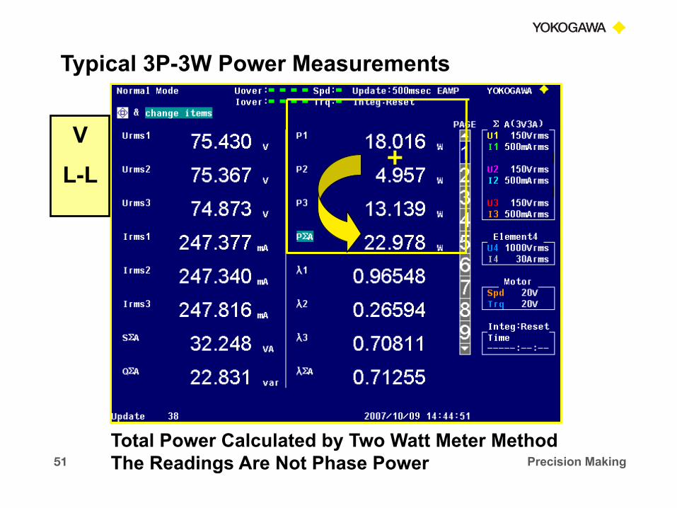
51 Precision Making
+
Total Power Calculated by Two Watt Meter Method The Readings Are Not Phase Power
V
L-L
Typical 3P-3W Power Measurements

52 Precision Making
3P-3W Motor Waveforms
Voltage Waveforms Connected Line to Line
Phase Current Waveforms
Typical 3P-3W Power Measurements
Motor & Drive Testing Copyright © Yokogawa Electric Corporation

53 Precision Making
60° 60°
Va
Vb Vc
Ic Ia
Ib
Vab
Vac
Vbc
Vac
Vbc
Vab
Ic Ia
Ib
The Phase Angle between the Voltage waveforms is 60 Degrees (NOT 120 Degrees) when the Power Analyzer is connected LINE-to-LINE.
The Phase Angle between the Current waveforms is 120 Degrees.
In this wiring configuration there is an additional 30 Degree Phase Shift between the Voltage and Current.
N
Phase difference between each voltage is 60 degrees in a balanced condition.
Vector of each parameter in a 3-phase 3-wire system with 3V3A wiring.
N
Three-Phase Three-Wire System with Three Meters
Motor & Drive Testing Copyright © Yokogawa Electric Corporation

54 Precision Making
§ What if you need to measure the Phase Power and Phase Power Factor on your 3-Phaes 3-Wire motor?
§ Following is a technique that will allow you to measure the Phase Parameters on a 3-Phase 3-Wire motor.
3P-3W Power Measurements Tip
Motor & Drive Testing Copyright © Yokogawa Electric Corporation

55 Precision Making
3-P 3-W System with “Floating Neutral”
Input Element 1 Input Element 2 Input Element 3
Floating Neutral
3P-3W Power Measurements Tip
Motor & Drive Testing Copyright © Yokogawa Electric Corporation
56 Precision Making
Caution . . . § This technique will work without problems
on the input to an Induction Motor, Synchronous Motor or similar motor without a Variable Speed Drive.
§ Use Caution when using on a Variable Speed Drive system. The High Frequency Distorted Waveforms and Harmonics can cause some inconsistent measurements.
Motor & Drive Testing Copyright © Yokogawa Electric Corporation
3P-3W Power Measurements Tip

57 Precision Making
Caution . . .
§ Use this technique Only on products with Sinewave type waveforms.
§ TIP – On a PWM Drive, Turn on the 500 Hz Line Filter (Low Pass Filter). The readings displayed will be that of the Fundamental Frequency, NOT total.
3P-3W Power Measurements Tip
Motor & Drive Testing Copyright © Yokogawa Electric Corporation

58 Precision Making
3P-3W
Voltage
Current
3P-4W
Voltage
Current
PWM Drive with 500 Hz Line Filter ON
3P-4W
Floating Neutral
3P-3W and 3P-4W Power Measurements

59 Precision Making
3P-3W 3P-4W F-N
P3P3W = P3P4W
PWM Drive with 500 Hz Line Filter ON & Floating Neutral
3P-3W and 3P-4W Power Measurements
U L-N x √ 3 = U L-L 55.20 x √ 3 = 95.60

60 Precision Making
V
L-L
V
L-N
Neutral Current
3P-3W and 3P-4W “Delta” Measurements
Motor & Drive Testing Copyright © Yokogawa Electric Corporation

61 Precision Making
P3P3W = P3P4W
L-N Voltage
Phase Power
L-L Voltage
+
+
Neutral Current
Delta Measurements Phase Power Measurement
Motor & Drive Testing Copyright © Yokogawa Electric Corporation

62 Precision Making 7/27/15
PART 5 Mechanical Power Measurements
On an AC Motor
Motor & Drive Testing Copyright © Yokogawa Electric Corporation

63 Precision Making
Load Motor
Three Phase AC Input
Speed and Torque Meter
Three Phase Power Analyzer
In-Line Speed & Torque Sensor
Mechanical Power Measurement
Motor & Drive Testing Copyright © Yokogawa Electric Corporation
64 Precision Making
n Various Manufacturers § Honeywell Sensotech - Lebow § S. Himmelstein and Company § Magtrol Inc § HBM § Others
n Various Types and Sizes of Sensors
n Contact the Sensor Manufacturer for Selection and Application Assistance
Speed & Torque Sensors
Motor & Drive Testing Copyright © Yokogawa Electric Corporation

65 Precision Making
S. Himmelstein and Company 2490 Pembroke Avenue Hoffman Estates, IL 60169 www.himmelstein.com
Digital Torquemeters
Digital Torquemeters
Mechanical Power Instrument
Speed & Torque Sensors Speed & Torque Sensors
Motor & Drive Testing Copyright © Yokogawa Electric Corporation

66 Precision Making
Honeywell Sensotec Sensors and Lebow Products www.honeywell.com/sensing
Speed & Torque Sensors
Signal Conditioner
Speed & Torque Sensors
Motor & Drive Testing Copyright © Yokogawa Electric Corporation
67 Precision Making
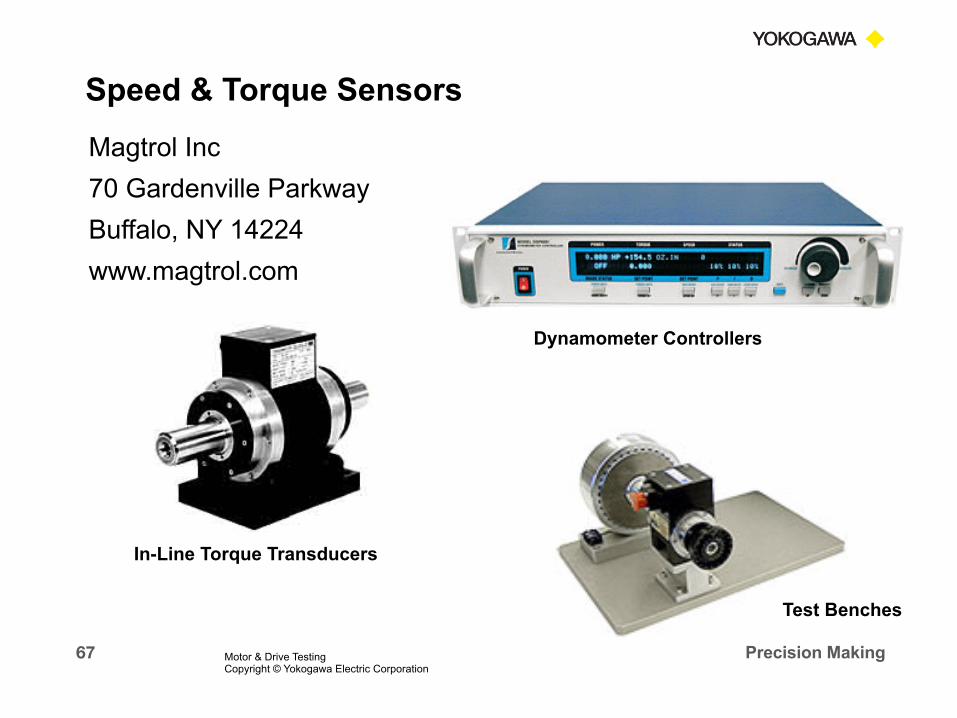
Magtrol Inc 70 Gardenville Parkway Buffalo, NY 14224 www.magtrol.com
In-Line Torque Transducers
Dynamometer Controllers
Test Benches
Speed & Torque Sensors
Motor & Drive Testing Copyright © Yokogawa Electric Corporation
Speed & Torque Sensors

68 Precision Making
System #1
Speed Sensor
Torque Sensor
Sensor Manufacturers Measurement Instrument
PC
Application Software
Use the Sensor Manufacturers Measurement System
Motor & Drive Testing Copyright © Yokogawa Electric Corporation
Mechanical Power Measurements

69 Precision Making
NovaTorque Test Fixture with Magtrol Speed/Torque Transducer, Brake and Dynamometer Controller
Motor Brake Speed & Torque Sensor
Motor & Drive Testing Copyright © Yokogawa Electric Corporation
Mechanical Power Test System

70 Precision Making
Advantages of System #1 n Sensor Manufacturers Measurement Instrument
§ Matched System to Sensors § Provides Proper Signal Conditioning § Readout for Torque, Speed & Power § Communication Output – RS232 & GPIB § Analog Output Signals – For other Readout Instruments
n Application Software
n Contact the Sensor Manufacturer for Selection and Application Assistance
Motor & Drive Testing Copyright © Yokogawa Electric Corporation
Mechanical Power Test System

71 Precision Making
System #2 Speed Sensor
Torque Sensor
Sensor Manufacturers Signal Conditioner
PC
Application Software
Use the Power Analyzer for Mechanical Power Measurements
Torque Signal
Speed Signal
Power Analyzer with Speed & Torque Input
Motor & Drive Testing Copyright © Yokogawa Electric Corporation
Mechanical Power Test System

72 Precision Making
Advantages of System #2
n Sensor Manufacturers Signal Conditioning § Matched System to Sensors § Provides Proper Signal Conditioning § Pulse and/or Analog Output Signal § Conditioned Speed & Torque Signals Provided for Power
Analyzer
n Power Analyzer Calculates the Electrical and Mechanical Power parameters § Electrical and Mechanical Measurements made
Simultaneously § Efficiency Calculations
n Custom or Generic Application Software Motor & Drive Testing Copyright © Yokogawa Electric Corporation
Mechanical Power Test System

73 Precision Making
Pulses/Revolution
Motor & Drive Testing Copyright © Yokogawa Electric Corporation
Power Analyzer Setup Menu

74 Precision Making Motor & Drive Testing Copyright © Yokogawa Electric Corporation
Speed and Torque Measurements

75 Precision Making 7/27/15
PART 6 PWM Drive Measurements
With an AC Motor
Motor & Drive Testing Copyright © Yokogawa Electric Corporation

76 Precision Making
Load Motor DC or Single Phase or Three Phase AC Input
Inverter
WT1800 Six-Phase Power Analyzer
Motor & Drive Testing Copyright © Yokogawa Electric Corporation
PWM Drive Measurements
77 Precision Making
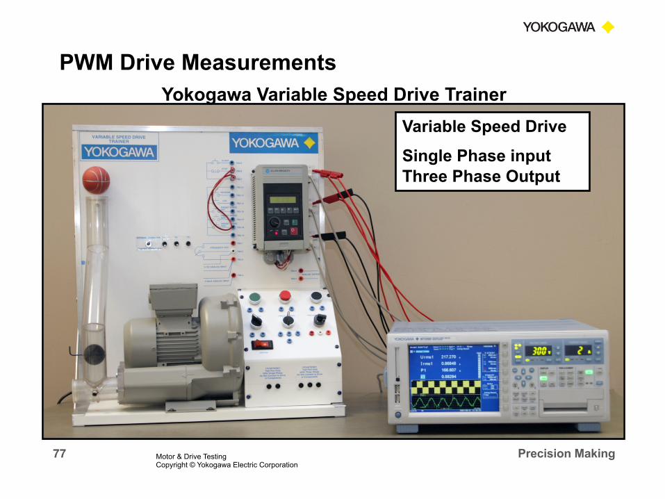
Yokogawa Variable Speed Drive Trainer Variable Speed Drive
Single Phase input Three Phase Output
Motor & Drive Testing Copyright © Yokogawa Electric Corporation
PWM Drive Measurements

78 Precision Making
PWM Voltage Waveform
Motor & Drive Testing Copyright © Yokogawa Electric Corporation
PWM Drive Measurements

79 Precision Making
n High Frequency Switching on the Voltage Signal § Voltage Driving Waveform is very Distorted § Very High Voltage Harmonic Content § Variable Frequency from 0 Hz up . . . .
n Current Signal contains a High Noise Level § Special Current Sensors required for Variable Frequency
measurements from 0 Hz up . . . . § Distorted Waveform with low level Harmonic Content.
n Accurate Power Measurements require Wide Bandwidth Power Analyzer
Motor & Drive Testing Copyright © Yokogawa Electric Corporation
PWM Drive Measurement Issues

80 Precision Making
Voltage Harmonic Content in Excess of 500 Orders - - Approximately 30 kHz
Motor & Drive Testing Copyright © Yokogawa Electric Corporation
Harmonic Spectrum of PWM Drive
81 Precision Making
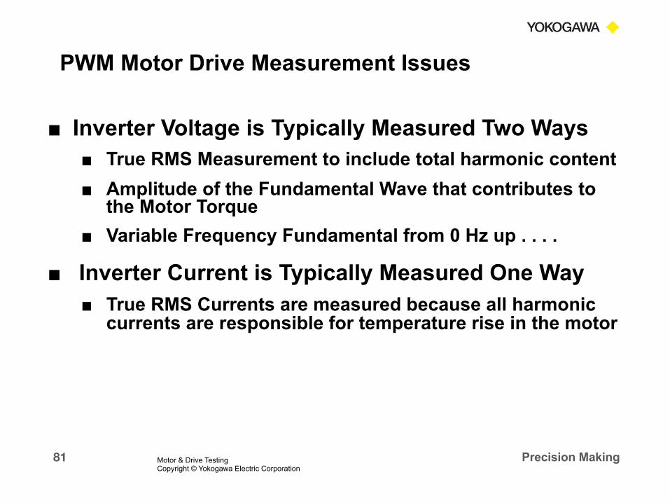
■ Inverter Voltage is Typically Measured Two Ways ■ True RMS Measurement to include total harmonic content ■ Amplitude of the Fundamental Wave that contributes to
the Motor Torque ■ Variable Frequency Fundamental from 0 Hz up . . . .
■ Inverter Current is Typically Measured One Way ■ True RMS Currents are measured because all harmonic
currents are responsible for temperature rise in the motor
Motor & Drive Testing Copyright © Yokogawa Electric Corporation
PWM Motor Drive Measurement Issues

82 Precision Making
How Do We Measure the Amplitude of the Fundamental Wave?
n Apply a Low Pass Filter
§ This will give a RMS Voltage of the Fundamental with the proper filter applied
§ Proper filter must be available in the instrument based on the Inverter Fundamental Frequency
§ It will also filter the Current and Power Measurements § Filtering is not a desirable method
Motor & Drive Testing Copyright © Yokogawa Electric Corporation
PWM Motor Drive Voltage Measurements

83 Precision Making
How Do We Measure the Amplitude of the Fundamental Wave?
n Rectified MEAN Measurement Method
§ This will give a RMS Voltage of the Fundamental without filtering
§ This method uses a Mean-Value Voltage Detection, scaled to RMS
§ The measured voltage will be very close to the RMS value of the fundamental wave
§ This has been an accepted method for many years
Motor & Drive Testing Copyright © Yokogawa Electric Corporation
PWM Motor Drive Voltage Measurements
84 Precision Making
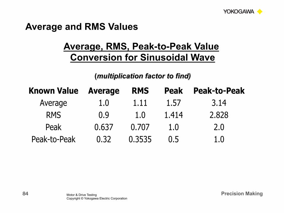
Average, RMS, Peak-to-Peak Value Conversion for Sinusoidal Wave
(multiplication factor to find)
Known Value Average RMS Peak Peak-to-Peak Average 1.0 1.11 1.57 3.14
RMS 0.9 1.0 1.414 2.828 Peak 0.637 0.707 1.0 2.0
Peak-to-Peak 0.32 0.3535 0.5 1.0
Average and RMS Values
Motor & Drive Testing Copyright © Yokogawa Electric Corporation

85 Precision Making
How Do We Measure the Amplitude of the Fundamental Wave?
n Harmonic Analysis to Determine True Fundamental Voltage § The Harmonic Analysis function uses a Fast Fourier
Transform, FFT, to determine the amplitude of each harmonic component
§ This will give an accurate RMS Voltage measurement of the Fundamental Wave
§ New Power Analyzers can make the True RMS Measurements simultaneously with the Harmonic measurements
Motor & Drive Testing Copyright © Yokogawa Electric Corporation
PWM Motor Drive Voltage Measurements

86 Precision Making
RMS
Mean
Filter
Fundamental
Motor & Drive Testing Copyright © Yokogawa Electric Corporation
PWM Motor Drive Voltage Measurements

87 Precision Making
n Drive Efficiency is Calculated as Output Power Divided by Input Power § Usually expressed as a percentage
n Use Two Power Meters to Measure the Input and Output Power § Calculate the Efficiency from the readings of the two Power Meters § Problem – Input and Output Readings may not be made Simultaneously. Possible error due to Time Skew
n Use a Multi-Element Power Analyzer to Measure Input and Output Power § Calculate the Efficiency in a Single Power Analyzer § Eliminates any Error due to Time Skew of Measurements
Motor & Drive Testing Copyright © Yokogawa Electric Corporation
PWM Motor Drive Efficiency Measurements

88 Precision Making
Drive Efficiency
Output P
Input P
Power Analyzer Setup Menu
Motor & Drive Testing Copyright © Yokogawa Electric Corporation
PWM Motor Drive Efficiency Measurements

89 Precision Making
n In Addition to Drive Efficiency, Drive Power Loss is
often a requested Measurement
n Several Yokogawa Power Analyzers offer a Function to Obtain this Measurement
n A “User Defined Math” function permits writing and equation for this measurement
n Power Loss = Input Power – Output Power
Motor & Drive Testing Copyright © Yokogawa Electric Corporation
PWM Motor Drive Power Loss

90 Precision Making
3V 3A Measurement Method Drive voltage is typically measured using the Mean value scaled to rms.
• DC Bus Voltage is measured as U+pk
Motor & Drive Testing Copyright © Yokogawa Electric Corporation
3-P 3-W PWM Motor Drive Power Measurement

91 Precision Making
Drive Efficiency
Drive Loss
Input Power
Output Power
Motor & Drive Testing Copyright © Yokogawa Electric Corporation
PWM Motor Drive Power Loss

92 Precision Making
n PWM Drives Should maintain a Constant Volts- Per-Hz Ratio to the Motor
n Verify that the V/Hz Ratio is maintained over the Speed Range of the Drive
n V/Hz can be calculated using the RMS or Fundamental Voltage Value
n The “User Defined Math” function permits writing an equation for this measurement
Motor & Drive Testing Copyright © Yokogawa Electric Corporation
PWM Motor Drive Volts-Per-Hertz Measurement

93 Precision Making
RMS
Fundamental
Motor & Drive Testing Copyright © Yokogawa Electric Corporation
Volts-Per-Hertz Math Function

94 Precision Making
RMS V/Hz
Fundamental V/Hz
Motor & Drive Testing Copyright © Yokogawa Electric Corporation
PWM Motor Drive Volts-Per-Hertz Measurement

95 Precision Making
n The DC Bus Voltage needs to be measured to check for Over and Under Voltage conditions
n The measurements can be taken inside the Drive on the terminals to the Capacitor bank
n If not accessible, use the Power Analyzer Waveform Display with Cursor Measurement
Motor & Drive Testing Copyright © Yokogawa Electric Corporation
DC Bus Voltage Measurement
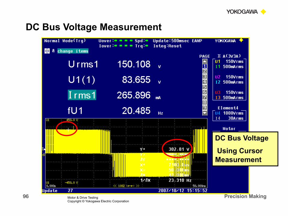
96 Precision Making
DC Bus Voltage
Using Cursor Measurement
Motor & Drive Testing Copyright © Yokogawa Electric Corporation
DC Bus Voltage Measurement
97 Precision Making
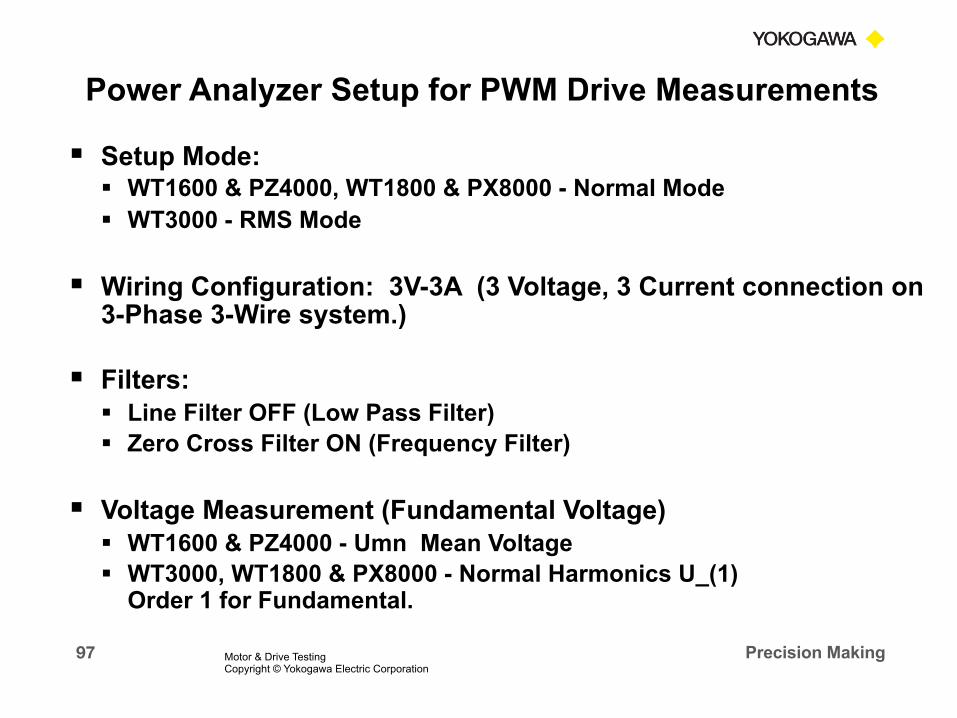
§ Setup Mode: § WT1600 & PZ4000, WT1800 & PX8000 - Normal Mode § WT3000 - RMS Mode
§ Wiring Configuration: 3V-3A (3 Voltage, 3 Current connection on 3-Phase 3-Wire system.)
§ Filters: § Line Filter OFF (Low Pass Filter) § Zero Cross Filter ON (Frequency Filter)
§ Voltage Measurement (Fundamental Voltage) § WT1600 & PZ4000 - Umn Mean Voltage § WT3000, WT1800 & PX8000 - Normal Harmonics U_(1)
Order 1 for Fundamental.
Motor & Drive Testing Copyright © Yokogawa Electric Corporation
Power Analyzer Setup for PWM Drive Measurements

98 Precision Making
PWM Inverter Output with Power Analyzer
Motor & Drive Testing Copyright © Yokogawa Electric Corporation
PWM Drive Measurements

99 Precision Making 7/27/15
PART 7 The Total System
Motor & Drive Testing Copyright © Yokogawa Electric Corporation
100 Precision Making
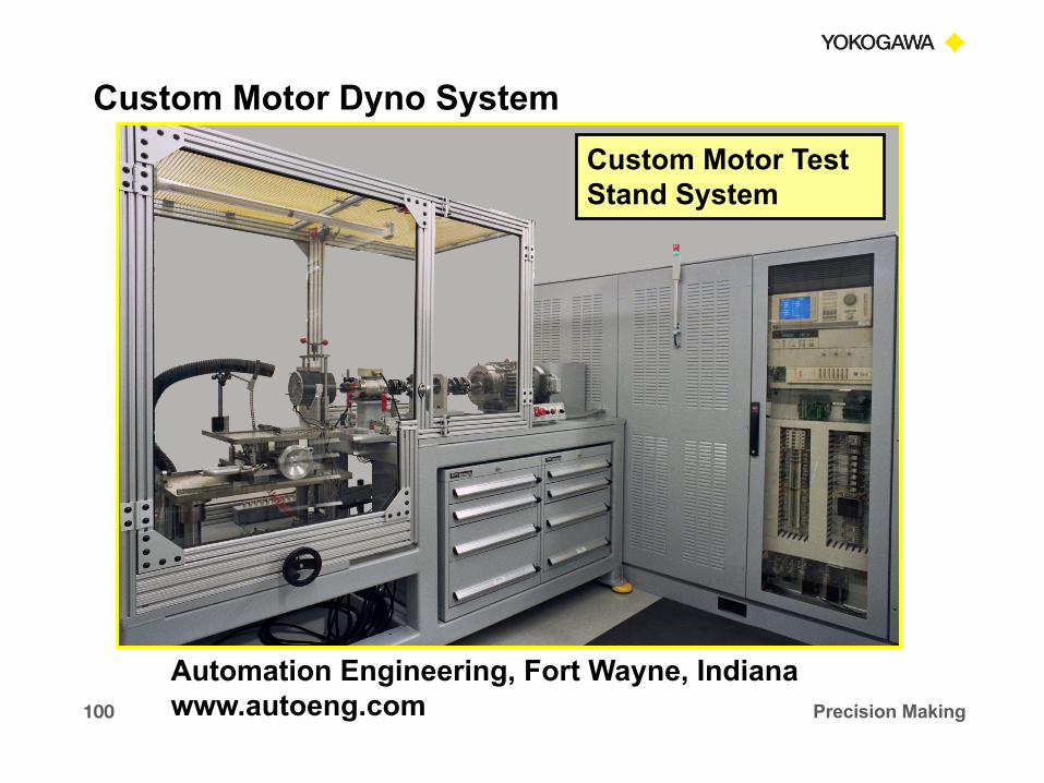
Automation Engineering, Fort Wayne, Indiana www.autoeng.com
Custom Motor Test Stand System
Custom Motor Dyno System

101 Precision Making
Three Step Measurement Process Motor & Drive System
Speed and Torque Meter
Load Motor DC or Single Phase or Three Phase AC Input
Inverter 1 2 3
Motor Test System
Motor & Drive Testing Copyright © Yokogawa Electric Corporation

102 Precision Making
Accurate Measurements of PWM Variable Speed Drive Input & Output Power § Calculate Drive Efficiency and Power Loss § Measure Other Drive Performance Functions
Accurate Measurements of Motor Input Power § Measure Electrical Performance of the Motor § Kilowatts, Horsepower, Power Factor,
Accurate Measurements of Motor Mechanical Power § Measure Motor Speed and Torque § Calculate Mechanical Power § Develop Speed Torque Curves
1
2
3
Motor Test System with Power Analyzer
Motor & Drive Testing Copyright © Yokogawa Electric Corporation
103 Precision Making
n Use the Power Analyzer for All Electrical and
Mechanical Power Measurements § All Measurements will be made Simultaneously § No Time Skew Error between Electrical & Mechanical
Measurements § Accurate Efficiency Calculations § Single Software Solution
Motor & Drive Testing Copyright © Yokogawa Electric Corporation
Motor Test System with Power Analyzer

104 Precision Making
Drive Efficiency
Total System
Efficiency
“Method A” Motor
Efficiency
Motor Test System with Power Analyzer
Motor & Drive Testing Copyright © Yokogawa Electric Corporation
Motor Test System with Power Analyzer

105 Precision Making
IEEE Std 112 Requirements
n IEEE Standard Test Procedure for Polyphase
Induction Motors and Generators § The Standard provides instructions for conducting and
reporting generally accepted tests for polyphase induction motors and generators
§ Procedures are defined for all parameters such as: Temperature Resistance Electrical Stator I2R Loss Rotor I2R Loss No-Load Test Efficiency Test Methods
§ Eleven different Test Methods are outlined and in IEEE Std 112 for the determination of Motor Efficiency!
Motor & Drive Testing Copyright © Yokogawa Electric Corporation
IEEE Std 112 Requirements

106 Precision Making
n Test Method A – Input-Output
§ The Efficiency is calculated as the Ratio of measured Output Power to the measured Input Power, after Temperature and Dynamometer corrections if applicable
§ Tests are to be done at Rated Load by means of a mechanical brake or dynamometer
§ This method should be limited to motors with Full Load Ratings of 1 kW or less
§ Eff =
Output Power
Input Power =
Pm
Electrical Input Power
Motor & Drive Testing Copyright © Yokogawa Electric Corporation
IEEE Std 112 Efficiency Test Methods

107 Precision Making
n Test Method B – Input-Output with Loss Segregation § In Method B, Input and Output Power are measured and
various losses are separated out. § Most of these losses just produce heat which must be
dissipated by the motor assembly. These losses are Energy which is not available to perform work.
§ This method is the recognized testing standard for the US Motor industry for motors with Full Load Ratings of 1 to 300 kW.
§ Typical Losses: Friction & Windage Core Loss Stator I2R Loss Rotor I2R Loss Stray-load Loss Apparent total Loss
§ All these calculation methods and procedures are outlined and defined in the Standard
IEEE Std 112 Efficiency Test Methods

108 Precision Making
n With several Accepted methods for determining Efficiency, which should I use? § For Electric Motor Manufacturers use Method A or Method
B based on motor size. § For Manufacturers of a Product using an Electric Motor, or
Motor & Drive System, use Method B if you have a Dyno and Equipment to make all Loss Measurements.
§ Otherwise, use Method A. § Remember – Your Efficiency Calculations may be different
than the Motor, Motor/Drive Manufacturers performance data
§ Key reasons for the differences might include – Test Method Test Load, Motor Speed, Other Test Conditions
Motor & Drive Testing Copyright © Yokogawa Electric Corporation
IEEE Std 112 Efficiency Test Methods

109 Precision Making
Voltage: Reading 480Range 600 Watt: Reading 554.517
Range 1,200.00Current: Reading 0.667 400
Range 1 425WT330
Entry LevelWT500
Mid RangeWT1800 High End
WT3000 Precision
Voltage Uncertainty (V) 1.08 1.08 0.78 0.228
Current Uncertainty (A) 0.001667 0.001667 0.001167 0.0003667
Watt Uncertainty (W) 1.754517 1.754517 1.154517 0.5909034
W % Reading Uncertainty
0.316% 0.316% 0.208% 0.107%
CT Uncertainty % Reading 0.02125% 0.02125% 0.02125% 0.02125%
System Uncertainty % Reading
0.319% 0.319% 0.212% 0.115%
CT Reading Uncertainty = (0.02% x Range) / Current Reading
Conditions: 3P3W, Unity PF, 60 Hz
CT 600:1
System Uncertainty = Sq Root of Sum of Squares (CT Un x 2) + Watt Un
Electrical System Accuracy
Square Root of Sum of Squares
CT Model M1114AK-A
YCA/LEM ITZ600-SPR Precision CT System
0.02% 0f Full Scale
Motor & Drive Testing Workshop Copyright © Yokogawa Electric Corporation

110 Precision Making 7/27/15
Conclusion
Motor & Drive Testing Copyright © Yokogawa Electric Corporation

111 Precision Making
u We Provided you with a Three Step Process for a Complete Electrical Test of an AC Motor & Variable Speed Drive System
Speed and Torque Meter
Load Motor
DC or Single Phase or Three Phase AC Input
Inverter
Motor & Drive Testing Copyright © Yokogawa Electric Corporation
In Conclusion
112 Precision Making
112
§ Reviewed Basic Power Measurements - n Including Electrical Power Measurements n Mechanical Power Measurements n Instrument Considerations & Current Sensors
§ Step 1: 3-Phase AC Motor Measurements n Three Phase Three Wire Measurements
§ Step 2: Mechanical Power Measurements n Speed and Torque Sensors n Motor Efficiency Measurements
In Conclusion In Conclusion
Motor & Drive Testing Copyright © Yokogawa Electric Corporation

113 Precision Making
113
§ Step 3: PWM Motor Drive Measurements n Input & Output Electrical Measurements n Drive Power Loss & Efficiency n Other Typical Drive Measurements
§ Motor and Drive System Measurements n Put All Three Steps Together n Total System Measurements & Efficiency n Reviewed IEEE Std 112 Testing Methods
§ Answered YOUR Power and Motor Measurement Questions
In Conclusion In Conclusion
Motor & Drive Testing Copyright © Yokogawa Electric Corporation

114 Precision Making
Ø Yokogawa offers the Most Complete Line of Power Analyzers to meet your Application and Budget.
Ø Product, Application and Software support provided from a network of Field Sales Reps, Factory Regional Sales Managers and Factory Support Application Engineers in Newnan, GA
Ø Guaranteed Measurement Accuracy over the Bandwidth of the Instrument. Available NIST Traceable and ISO17025 Calibration provided by Factory Trained technicians in Newnan, GA. Ø All Yokogawa Power Analyzers are covered by a 3-Year Warranty.
Where Power Meets Precision Copyright © Yokogawa Electric Corporation
Conclusion

115 Precision Making
Precision Power Analyzers
Yokogawa’s Power Measuring Solutions
Where Power Meets Precision Copyright © Yokogawa Electric Corporation

116 Precision Making
Digital Oscilloscopes with Power Analysis
Yokogawa’s Power Measuring Solutions
Where Power Meets Precision Copyright © Yokogawa Electric Corporation

117 Precision Making 7/27/15
Future Webinars
Where Power Meets Precision Copyright © Yokogawa Electric Corporation

118 Precision Making Where Power Meets Precision Copyright © Yokogawa Electric Corporation
Join Us for Future Web Seminars
Visit our Web Site
tmi.yokogawa.com
Go to > Technical Library
> Webinars On-Demand

119 Precision Making
ü Basic Power Measurements: May 13 ü Harmonic Analysis: June 24
ü Motor Analysis: July 22 • Archived at tmi.yokogawa.com > Technical Library
> Webinars On-Demand
• Register for future Webinars
• Upcoming ScopeCorder Application Webinar
Where Power Meets Precision Copyright © Yokogawa Electric Corporation
Educational Webinars:

120 Precision Making
Ø Count the Number of Electric Motors in your House Ø Here are some Tips
• Kitchen Appliances • HVAC Systems • Home Entertainment • Home Office • Lawn Equipment • Others
Ø Make it a FUN Family project - OR a FUN Family competition
Where Power Meets Precision Copyright © Yokogawa Electric Corporation
Fun With Motors

121 Precision Making
Thank You
For
Attending
Where Power Meets Precision Copyright © Yokogawa Electric Corporation

122 Precision Making
Yokogawa Corp of America Test & Measurement Div.
2 Dart Rd. Newnan, GA 30265 tmi.yokogawa.com Tel: 1-800-888-6400
Bill Gatheridge Product Manager Ext 5454 [email protected]
Contact Us
Where Power Meets Precision Copyright © Yokogawa Electric Corporation