Embed Size (px)
Citation preview

Tel: 201-342-3338 Fax: 201-342-3339 www.cciproducts.com
Technical Description
General Information
CCI’s Multi-Carrier Cell Extender System breaks with traditional integration concepts and sets a new di-rection with our seamlessly integrated direct mounting systems. Derived from our SCPA product line, our MCPA hanging cabinets and enclosures re-quire no dedicated pad space, saving valuable de-ployment time and cost. The system employs a new highly efficient MCPA design that is an integral part of CCI’s complete turn-key MCPA system. High power density of the MPCA module and power plant create a powerful compact package. The MCPA system supports multiple simultaneous for-mats such as GSM/EDGE, CDMA1X/DO, and UMTS. Multiple radios are combined on high capacity sites to reduce the required number of feeders without
impacting coverage. CCI’s MCPA is a key element in upgrading or cositing existing (growth) or new base stations. Fail-safe Bypass Mode assures that antenna connection to the BTS is not lost. Optional N+1 redundancy con-figurations and integrated VSWR monitoring with I/P addressability are available.
Contents
CCI’s MCPA employs a high efficiency Feed Forward design that works with multiple modulation formats simultaneously. Multi-Loop architecture reduces the number of components and increases reliability. An internal microprocessor circuit controls all functions, maintains long term (thermal) and short term (distortion) functions, and generates status and alarms. An auto-reboot feature will automatically restart the MCPA module in case of power interruptions. Fans are alarmed and hot swappable, requiring only common tools to change. Module efficiency is greater than 16% due to an advanced Doherty type architecture which also reduces current consumption during low traffic periods. Intermodulation distortion is extremely low, better than –65 dBc typical, due to a custom pre-linearizer circuit. Dry contact alarms are also pro-vided for simple interface to existing base station alarm reporting circuits.
Model CE-850-200MC
1 CCI Confidential
CDMA Multi-Carrier Cell Extender System With Cellular 200 Watt MCPA
Configuration and Specifications
CDMA Cellular Edition
General Info 1
Technical Description 1
Electrical Specifications 2
Mechanical Specifications 3
Module Locations 5
Block Diagrams & Module Configurations 15 - 22
Outdoor Cabinet Outline 23
Ordering Information 23
Indoor Rack Outline 24
Secondary CE Modules 10-11
MCPA Specifications 4
Duplexer/Attenuator Techni-cal Description & Specs. 6-9
Alarm Board & Alarm Interface 12
Power Supplies 13
Optional Equipment 14

Communication Components Inc. CDMA Multi-Carrier Cell Extender System With Cellular 200 Watt MCPA
CDMA Multi-Carrier Cell Extender System Level Specifications
Description Typical Specifications
Electrical Forward Link (Downlink) Reverse Link (Uplink)
Frequency range of operation 869 - 894 MHz (U.S. Cellular Band) 824 - 849 MHz (U.S. Cellular Band)
Usable Composite Output Power 200 Watts (Referenced to PA Mod-ule Output connector)
Operational Bandwidth 25 MHz (869 - 894 MHz)
System Gain
Adjustable to 13 dB in 0.5 dB steps - via Software Adjustable to 13 dB in 1 dB steps - via DIP Switch
16 dB - Std. TMA
15 dB - TMA with SMRR Option
Gain Variation ± 0.75 dB Max. ± 0.5 dB Max.
Passband Flatness ± 1.0 dB Max. ± 0.5 dB Max.
Harmonics and In-Band Emissions -13 dBm Max. (FCC emissions limits) N/A
System Group Delay 180 nSec Max.
Input/Output VSWR 1.5:1 Max. 1.5:1 Max.
Up-Link-Down-Link Isolation 90 dB
Uplink Noise Figure
1.5 dB Typ. - Std. (Referenced to Antenna Port, with TMA)
1.7 dB Typ. - SMRR (Referenced to Antenna Port, with TMA)
Power Supply Voltage +21V DC to +28V DC (+27.0V DC nominal, +25.5 to +28.0V DC meeting all specifications)
Input Power Options +27 VDC PDU (+26 to +28 VDC)
220 VAC (AC PPS) Battery Backup Optional
DC Current Draw 46 Amps Max per PA Module (At nominal voltage and Max Rated Pout)
Power Consumption 1.5 KW Max. per Sector @ 27 VDC (46A DC @ +27 VDC/Amplifier)
C o m m u n i c a t i o n C o m p o n e n t s I n c .
2 Tel: 201-342-3338 Fax: 201-342-3339
CCI Confidential
Communication Components Inc. CDMA Multi-Carrier Cell Extender System With Cellular 200 Watt MCPA
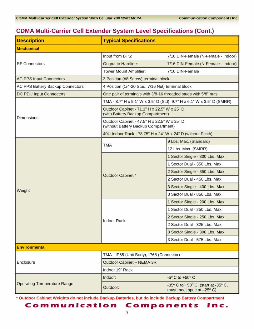
CDMA Multi-Carrier Cell Extender System Level Specifications (Cont.) Description Typical Specifications Mechanical
RF Connectors
Input from BTS: 7/16 DIN-Female (N-Female - Indoor)
Output to Hardline: 7/16 DIN-Female (N-Female - Indoor)
Tower Mount Amplifier: 7/16 DIN-Female
AC PPS Input Connectors 3 Position (#8 Screw) terminal block
AC PPS Battery Backup Connectors 4 Position (1/4-20 Stud, 7/16 Nut) terminal block
DC PDU Input Connectors One pair of terminals with 3/8-16 threaded studs with 5/8” nuts
Dimensions
TMA - 8.7” H x 5.1” W x 3.5” D (Std); 9.7” H x 6.1” W x 3.5” D (SMRR)
Outdoor Cabinet - 71.1” H x 22.5” W x 25” D (with Battery Backup Compartment)
Outdoor Cabinet - 47.5” H x 22.5” W x 25” D (without Battery Backup Compartment)
40U Indoor Rack - 78.75” H x 24” W x 24” D (without Plinth)
Weight
TMA 9 Lbs. Max. (Standard)
12 Lbs. Max. (SMRR)
Outdoor Cabinet *
1 Sector Single - 300 Lbs. Max.
1 Sector Dual - 350 Lbs. Max.
2 Sector Single - 350 Lbs. Max.
2 Sector Dual - 450 Lbs. Max.
3 Sector Single - 400 Lbs. Max.
3 Sector Dual - 850 Lbs. Max.
Indoor Rack
1 Sector Single - 200 Lbs. Max.
1 Sector Dual - 250 Lbs. Max.
2 Sector Single - 250 Lbs. Max.
2 Sector Dual - 325 Lbs. Max.
3 Sector Single - 300 Lbs. Max.
3 Sector Dual - 575 Lbs. Max.
Environmental
Enclosure
TMA - IP65 (Unit Body), IP68 (Connector)
Outdoor Cabinet – NEMA 3R
Indoor 19” Rack
Indoor: -5º C to +50º C
Outdoor: -35º C to +50º C, (start at -35º C, must meet spec at –25º C)
Operating Temperature Range
3
C o m m u n i c a t i o n C o m p o n e n t s I n c . * Outdoor Cabinet Weights do not include Backup Batteries, but do include Backup Battery Compartment

200 Watt Multi-Carrier Power Amplifier Module (MCPA)
Description Typical Specifications* Electrical Specifications
Frequency range of operation 869 - 894 MHz
Operating Bandwidth 40 to 60 MHz
Output Power 200 Watts
Gain 63 dB
Gain variation over temperature ± 0.75 dB
Passband flatness ± 1.0 dB
Module Efficiency 16.5%
Module Current Draw @ 200 Watts Output 46 Amps
Operating Voltage 26 to 28 VDC
Out of Band Spurious Meets FCC
Input return loss (VSWR) > 15 dB (1.4:1)
Output Return Loss (VSWR) > 15 dB (1.4:1)
Mechanical Specifications
Dimensions 3.9” x 13.4” x 17.5”
Weight 30 Pounds
Operating Temperature Range -35º C to +65º C (start at -35º C, must meet spec at –25º C)
Operating Relative Humidity 0% to 99%
Operating Altitude Up to 13,000 FT
Environmental Specifications
C o m m u n i c a t i o n C o m p o n e n t s I n c .
4 Tel: 201-342-3338 Fax: 201-342-3339
Communication Components Inc. CDMA Multi-Carrier Cell Extender System With Cellular 200 Watt MCPA
* Note: with 8 GSM and 1 UMTS carriers
Features & Benefits ♦ Low IMD Products - 65 dBc ♦ Hot Swappable Fans ♦ Works with all Modulations ♦ High Efficiency
CCI Confidential

Communication Components Inc. CDMA Multi-Carrier Cell Extender System With Cellular 200 Watt MCPA
Standard CDMA Module locations
AC Rectifier / PDU with N+1 Redundancy
Optional PDU for TMAs with Antenna VSWR Monitoring
200W Feed Forward MCPA Modules
4 modules max
Combiner/Duplexer Modules
Auto sensing Bypass module
5 CCI Confidential
I/O Signal Plate (with Bias-T’s
mounted underneath)
Alarms
RESET/STROBE
Power Distribution Unit+-
654321DC INPUT
(EITHER POLARITY)
PSU
MO
DE
L# R
EC
-100
A-2
7V
SN: MO
DE
L# R
EC
-100
A-2
7V
SN:MO
DE
L# R
EC
-100
A-2
7V
SN:
ON1
0OFF
10
ON1
0OFF
10
BATT O
N
MOD FAIL
AC PWR ON
1 432
5
60 6606060
INPUT 01
OUTPUT 01
DATA
ATTEN 01
PWR/ALM
INPUT 02
OUTPUT 02
ATTEN 02
DUAL ATTENUATOR MODULE
LOCREM1 dB2 dB4 dB8 dB
16 dB
TOTAL ATTEN 42 dB
+
LOCREM1 dB2 dB4 dB8 dB16 dB
TOTAL ATTEN 42 dB
+
TX
TX
TX/
RX
TX/
RX
FROM MCPA
TOATTEN
BTS
ANT
TRANSMIT DUPLEXER MODULE 01
TX
TX
TX/
RX
TX/
RX
FROM MCPA
TOATTEN
BTS
ANT
TRANSMIT DUPLEXER MODULE 02
OUT
IN
850 MH
z MC
PA
ACT
ALM
ON
OFF
OUT
IN
850 MH
z MC
PA
ACT
ALM
ON
OFF
OUT
IN
850 MH
z MC
PA
ACT
ALM
ON
OFF
OU
T
IN
850 MHz M
CPA
AC
TA
LM
ON
OFF
MCPA BYPASS MODULE
12
34
12
34
S1 S4S3S2
MODEL # BYP-0821-200-X-YPWR
S6S5
12
34
12
34
SECTOR 1 (Inputs)
SECTOR 2 (Inputs)
SECTOR 3 (Inputs)
SECTOR 1 (Outputs)
SECTOR 2 (Outputs)
SECTOR 3 (Outputs)
AC JUNCTION BOX
AC TO PPS (3-Wire)
TO BATT. POS. (1 Wire)
TO BATT. NEG. (1 Wire)
Mul
ti-W
ire A
larm
TX1/RXATX2/RXBTX1/RXATX2/RXBTX1/RXATX2/RXB
ANT AANT BANT AANT BANT AANT B
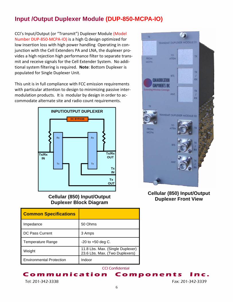
Input /Output Duplexer Module (DUP-850-MCPA-IO) CCI’s Input/Output (or “Transmit”) Duplexer Module (Model Number DUP-850-MCPA-IO) is a high Q design optimized for low insertion loss with high power handling Operating in con-junction with the Cell Extenders PA and LNA, the duplexer pro-vides a high rejection high performance filter to separate trans-mit and receive signals for the Cell Extender System. No addi-tional system filtering is required. Note: Bottom Duplexer is populated for Single Duplexer Unit. This unit is in full compliance with FCC emission requirements with particular attention to design to minimizing passive inter-modulation products. It is modular by design in order to ac-commodate alternate site and radio count requirements.
Common Specifications
Impedance 50 Ohms
DC Pass Current 3 Amps
Temperature Range -20 to +50 deg C.
Weight 11.8 Lbs. Max. (Single Duplexer) 23.6 Lbs. Max. (Two Duplexers)
Environmental Protection Indoor
C o m m u n i c a t i o n C o m p o n e n t s I n c .
6 Tel: 201-342-3338 Fax: 201-342-3339
CCI Confidential
Rx
Tx
Rx
Tx
Tx IN
Tx OUT
Tx/Rx OUT
Tx/Rx IN
INPUT/OUTPUT DUPLEXER
DC BYPASS
Cellular (850) Input/Output Duplexer Block Diagram
Cellular (850) Input/Output Duplexer Front View

Input / Output Duplexer Module (DUP-850-MCPA-IO)
Description Typical Specifications Input Tx Path
Passband 869 MHz - 894 MHz Insertion Loss 0.5 dB Typical, 1.0 dB Max. Amplitude Ripple 0.15 dB Max / 3.84 MHz Band Group Delay 20 nSec Max / 3.84 MHz Band Phase Ripple 40 Deg Max / 3.84 MHz Band Return Loss 15 dB Minimum Power Handling 100 W Average, 1KWatt Peak
Rx Band Rejection 60 dB Minimum (824 MHz - 849 MHz)
Output Tx Path
Passband 869 MHz - 894 MHz Insertion Loss 0.5 dB Typical, 1.0 dB Max. Amplitude Ripple 0.35 dB Max / 3.84 MHz Band Group Delay 60 nSec Max / 3.84 MHz Band Phase Ripple 80 Deg Max / 3.84 MHz Band Return Loss 15 dB Minimum Power Handling 200 W Average, 5KWatt Peak Rx Band Rejection 86 dB Minimum (824 MHz - 849 MHz) IMD within Rx Band -150 dBc min (2 x 100 Watt tones)
Passband 824 MHz - 849 MHz Insertion Loss 0.5 dB Typical, 1 dB Max. Amplitude Ripple 0.25 dB Max / 3.84 MHz Band Group Delay 25 nSec Max / 3.84 MHz Band Phase Ripple 40 Deg Max / 3.84 MHz Band Return Loss 15 dB Minimum Tx Band Rejection 60 dB Minimum (869 MHz - 894 MHz)
Rx Path
C o m m u n i c a t i o n C o m p o n e n t s I n c .
7 Tel: 201-342-3338 Fax: 201-342-3339
CCI Confidential
Cellular (850) Input/Output
Duplexer Front View

Dual Attenuator Module (ATT-850-2)
Dual Attenuator Front View
Dual Attenuator Rear View
Digital/Manual Control
Input 01
Input 02
Output 01
Output 02
42 dBm
42 dBm
Ethernet (RJ45 Connector )
Dual Attenuator Module Block Diagram
CCI’s Dual Attenuator Module (Model Number ATT-850-2) is used to set the correct system gain for one or two channels (“active Antennas”) per sector as required. The Dual Attenu-ator Module is available in either the PCS or Cellular fre-quency bands. Overall system gain is adjustable with this module. CCI’s Dual Attenuator Module provides two pairs of Input (01 and 02) and Output (01 and 02) ports with attenua-tion values ranging from 42 dB (when no additional internal attenuation is set) to 73 dB (when all attenuation is set to “ON”) in 1 dB increments ”Manually” via DIP Switch or in 0.5 dB increments when performed via Remote (Software Con-trolled). Attenuator value can be set for either Local or Re-mote operation. Local operation of each attenuator is per-formed by setting the LOC/REM switch on the DIP Switch to the LOC position, and then selecting the value of attenuation required at the DIP switch. Remote operation is performed through input to the “DATA” (RJ45) port via Ethernet connec-tion to the Dual Attenuator Module. The LOC/REM and at-tenuation switches can be “Hot Switched” (i.e. switched while power is applied). DC Connection is at the rear of the module via a header which connects to the DCA chassis (tray) and provides power for fan operation, remote attenuator control, alarm circuitry and LED status indicators. Dry con-tact alarms are provided via the “DATA” RJ45 connector for simple interface to CCI’s Alarm Board typically located below the Bypass Module at the bottom of the Cell Extender Out-door Cabinet, or behind the DCA Tray near the top of the Cell Extender Indoor Rack.
C o m m u n i c a t i o n C o m p o n e n t s I n c .
8 Tel: 201-342-3338 Fax: 201-342-3339
CCI Confidential

Dual Attenuator Module (ATT-850-2)
Description Typical Specifications Electrical
Operating Frequency Band 869 MHz –894 MHz Nominal Input/Output Impedance 50 Ohm
Attenuation at 0 dB Setting 42 dB ±1.5 dB
Normalized Attenuation Range 0 - 31 dB in 0.5 dB steps - via Software; 0 - 31 dB in 1 dB steps - via DIP Switch
Port Return Loss 15 dB Minimum
Power Handling 100W Average, 1 KW Peak
DC Supply Voltage 30 VDC Max., 22-30 VDC
DC Supply Current 650 mA Max/
Indicators
Green Power Supply OK Red Fan Alarm Mechanical Number of Inputs/Outputs 2 Inputs / 2 Outputs
RF Connectors 2 x SMA-Female - ”OUTPUT 01” & “OUTPUT 02” (Tx Out to MCPA) 2 x N-Female - ”INPUT 01” & “INPUT 02” (Tx In for I/O Duplexer)
DC Power Connector Type 2 pin Tyco header Type MTA-100 (0.025” Sq. pins on 0.100” Centers)
Fan Connector Type 3 pin Tyco header Type MTA-100 (0.025” Sq. pins on 0.100” Centers)
Remote Interface/Alarm (Data) Connector RJ45 (Alarm & RS485 Signal Lines)
Attenuator Control 6 position DIP Switch
Dimensions 10.5” H x 1.75” W x 5.5” D
Weight 2.5 Lbs. Max
Environmental
Operating Temperature -20 to +50 deg C. Environmental Protection Indoor
C o m m u n i c a t i o n C o m p o n e n t s I n c .
9 Tel: 201-342-3338 Fax: 201-342-3339
CCI Confidential
Dual Attenuator Front View

Secondary Cell Extender Modules Bypass Module—P/N BYP-0821-200-X-Y The optional bypass module utilizes the latest high power switching technology to achieve full bypass functionality of up to six MCPA modules in the event of an MCPA failure or power outage. The BPM is rated for the full peak output power of the MCPA’s and is able to operate with all common modulation types, CDMA, W-CDMA, UMTS, GSM and EDGE. Six MCPA Modules are only utilized when a 3-Sector Dual MCPA is requested, otherwise three or four MCPA’s are typically utilized. Note: X = the number of RF Switches utilized, and Y = “O” for Outdoor, or “I “ for Indoor configuration. Also note: RF Switches for the Indoor configuration are rotated 180° from the Outdoor configuration, due to the point of cable entry.
C o m m u n i c a t i o n C o m p o n e n t s I n c . Tel: 201-342-3338 Fax: 201-342-3339
CCI Confidential
MCPA Bypass Module Configured for a 2-Sector Dual MCPA per Sector Front View
MCPA Bypass Module Configured for a 2-Sector Dual MCPA per Sector Rear View Bypass Module Block Diagram (Failure Mode)
From “TX1/RXA” (BTS) connection
on I/O Signal Plate
To “BTS // TX/RX” connection on
Transmit Duplexer
Pin 4 (on RF Switch)
Pin 3 (on RF Switch)
Pin 1 (on RF Switch)
Pin 2 (on RF Switch)
From “ANT // TX/RX” connection on
Transmit Duplexer
To “ANT A” connection on I/O
Signal Plate
Bypass Switch Module Block Diagram (Normal Mode) Bypass Switch Module Block Diagram (Failure Mode)
10

Secondary Cell Extender Modules N+1 Redundancy Switch Module - P/N MCPA-RDD CCI’s N+1 Redundancy Switch (a matrixed switch array) provides a means of redirecting (re-routing) the RF signals from the input and output of a failed MCPA Module to the input and output of a “Spare” MCPA Module. This allows the “amplified” signal to continue to be available in the event of an MCPA failure. When a failure of one of the MCPA’s occurs, the operation of CCI’s CDMA Cell Extender System is trans-parent to the BTS as long as the remaining MCPA’s continue to operate. Indication of the Alarm status will be transmitted to the BTS thereby allowing the Carrier (Provider) to request repair/replacement of the failed MCPA. DC Input connection is made at the rear of the N+1 Redundancy Switch. The N+1 Re-dundancy requires DC input in order to provide power for alarm circuitry, LED status indicators and to power the multiple “RF Switches” that “switch” the RF signal path in the event of an MCPA failure. Simi-larly, dry contact alarms are also provided at the rear of the N+1 Redundancy Switch for simple interface to CCI’s Alarm Board typically located below the Bypass Module at the bottom of the Cell Extender Out-door Cabinet, or behind the DCA Tray near the top of the Cell Extender Indoor Rack.
N+1 Redundancy Switch Module Front View
N+1 Redundancy Switch Module Block Diagram
C o m m u n i c a t i o n C o m p o n e n t s I n c .
11 Tel: 201-342-3338 Fax: 201-342-3339
CCI Confidential

Alarm Board and Alarm Interface Details MCPA System Alarm Interface Board—P/N 205203 CCI’s MCPA System Alarm Interface Board enables notification of Ma-jor and Minor Alarms from the 200W Cell Extender to the CDMA BTS. Summary alarms are available via the use of a Connector Converter Board, Bypass Module Control Board (within the Bypass Module) and an Alarm Interface Board on a per rack basis by way of an alarm col-lection kit, enabling notification of Major failures (e.g. amplifier fail-ure) as well as Minor failures (e.g. fan failure). These alarms may be tied in to the existing alarm block at the site for remote notification. The Connector Converter Board is used to convert 20 pin connections from the MCPA Modules to RJ-45 connections (8 pins) and for connection of the 30 pin N+1 Redundancy Module to control the MCPA Modules (when applicable). Note: If a 3-Sector Dual MCPA for Two Active An-tenna solution is performed then a 2nd Connector Converter Board and a 2nd Alarm Interface Board (connected in series to the 1st Alarm Interface Board) will be required. There are nine alarm ports on the MCPA Alarm Collection Board. Connector P2 contains four RJ45 Jacks which are for connection to MCPA 2, MCPA 3, MCPA 4 and PDU (TMA PDU) Alarm Inputs from the 200W Cell Extender equipment Modules. Connector P1 contains five RJ45 jacks which are for connection to MCPA 1, Combiner 1, Combiner 2, Combiner 3 and PSU (Triple Rectifier AC PPS or DC PDU) Alarm Inputs from the 200W Cell Extender modules. Additionally there are two “Bypass/Enable” DIP Switches on the board. The DIP Switches should be set to “Enable” only if connection from a module is present at the terminal of inter-est. See the figure below for an “Alarm Bypass Configuration Block Diagram.” Note that the diagram is based on a Standard 2-Sector Dual MCPA (showing connections for up to 4 MCPA’s) Solution.
12 CCI Confidential
CO
MB
O-D
CO
MBO
-DC
OM
BO
-DC
OM
BO
-D
12
34
12
34
12
34
12
34
20 P
in M
olex
20 P
in M
olex
20 P
in M
olex
20 P
in M
olex
MC
PA2
PPU
MC
PA
4M
CPA
3
CO
MB
1M
CP
A1
CO
MB
3C
OM
B2
PSS
14
23
5
14
23
O N
O N
Alarm Bypass Configuration Block Diagram

Converts 220VAC into 27VDC for MCPA and other modules. Consists of two primary and a third redundant (N+1) plug-in. The entire Cell Extender is powered by the two primary modules, the third serves as a backup in case of loss of either of the two primary units. The PPS also includes pro-visions for optional battery back-up solutions and is available in two ver-sions in order to accommodate the various options available. This unit is available with or without battery charging circuitry.
AC Power System with Rectifiers—P/N— PPS-300A-27V-BAT
Triple Rectifier AC Power System (Two Rectifier Modules Installed) - Front Panel
100 Amp Rectifier Module
+27V DC Power Distribution Unit - P/N - PDU-200A-27V
+27V DC Power Distribution Unit Front Panel
The +27V DC Power Distribution Unit provides a local breaker point for up to four MCPA Modules @ 60A DC each and two Auxiliary Equipment breakers @ 10A DC each, when an existing +27V DC power source is available.
+27V DC Power Distribution Unit Rear Panel
Triple Rectifier AC Power System (Two Rectifier Modules Installed) - Rear Panel
C o m m u n i c a t i o n C o m p o n e n t s I n c .
13 Tel: 201-342-3338 Fax: 201-342-3339
CCI Confidential

VSWR Monitor / TMA Power Distribution Unit (VPDU) - Optional
Bias-T / VSWR Monitor Unit
(BTV)
AISG 2.0 Site Control Unit (SCU) - (a.k.a. Remote Electrical Tilt Controller ) - Optional
CCI’s optional VPDU has all of the features of a traditional PDU, and adds VSWR monitoring/data collec-tion and Universal compatibility with any TMA. A single PDU powers all TMA’s on the site. The unit is operated from its front panel, or via integrated HTML interface over I/P. The VSWR measurements and alarm status are also available on the front panel or via I/P. With the addition of CCI’s Bias-T/VSWR Monitor modules (BTV), VSWR can be measured accurately on each line. Each BTV is simply placed where an ordinary Bias-T is located.
The AISG 2.0 Site Control Unit (SCU), or Remote Electrical Tilt Controller is part of Communication Compo-nent Inc.’s complete Remote Antenna Tilt System. The Remote Tilt Antenna enables optimization on a con-tinuous basis of the sector coverage pattern. The Tilt Controller interfaces directly with the CCI Tilt Actuator mounted at the Antenna There are three RS485 Remote Control (or Antenna Line Device (ALD) output inter-faces (8 pin female circular connector per IEC 60130-9) which are AISG2.0 compatible and provide a complete multi sector solution. The Tilt Controller when used with RET Tilt Actuators enables remote fine tuning of the BTS footprint without tower climb. The continuous adjustment capability allows changes to the BTS coverage to suit network optimization, changing traffic patterns or seasonal changes such as foliage absorption. The unit can be controlled via a Ethernet port, RS232 or manual input.
The Remote Electrical Tilt Controller is designed for Indoor rack mount environments and runs off 24V DC to 48V DC, either polarity. The unit is fully lightning protected.
The Remote Electrical Tilt Controller can feed a maximum of 450 feet and can be daisy chained to up to 9 in-dividual Tilt Actuators. Additionally, with the use of AISG compliant Bias-Ts the SCU can power and control up to three AISG compliant, variable gain TMA’s. The Bias-T’s not only provide power for the TMA’s thru the Feeder Lines, but also carry the RS-485 signals to the TMA’s. The TMA’s also have AISG compliant outputs which can then be connected to RET Tilt Actuators for their control and adjustment.
VSWR Monitor / TMA Power Distribution Unit—Front Panel
Bias-T / VSWR Monitor Unit (BTV) 3D View
Bias-T / VSWR Monitor Unit (BTV) Bias/Signal Connector End View
14

Communication Components Inc. CDMA Multi-Carrier Cell Extender System With Cellular 200 Watt MCPA
AC Rectifier & Power Distribu-tion with N+1 Redundancy
Optional TMA and VSWR Monitoring PDU
Triple 200W MCPA Modules
Triple Combiner/Duplexer Modules
Optional Base Unit for battery storage
Outdoor Three Sector Multi-Carrier Power Amplifier (MCPA) System
Auto sensing Bypass Module
C o m m u n i c a t i o n C o m p o n e n t s I n c .
15 Tel: 201-342-3338 Fax: 201-342-3339
CCI Confidential
I/O Signal Plate (with Bias-T’s mounted underneath)
Battery Backup Compartment
Alarms
RESET/STROBE
Power Distribution Unit+-
654321DC INPUT
(EITHER POLARITY)
PSU
INPUT 01
OUTPUT 01
DATA
ATTEN 01
PWR/ALM
INPUT 02
OUTPUT 02
ATTEN 02
DUAL ATTENUATOR MODULE
LOCREM1 dB2 dB4 dB8 dB
16 dB
TOTAL ATTEN 42 dB
+
LOCREM1 dB2 dB4 dB8 dB16 dB
TOTAL ATTEN 42 dB
+
TX
TX
TX/
RX
TX/
RX
FROM MCPA TO
ATTEN
BTS
ANT
TRANSMIT DUPLEXER MODULE 01
TX
TX
TX/
RX
TX/
RX
FROM MCPA TO
ATTEN
BTS
ANT
TRANSMIT DUPLEXER MODULE 02
INPUT 01
OUTPUT 01
DATA
ATTEN 01
PWR/ALM
INPUT 02
OUTPUT 02
ATTEN 02
DUAL ATTENUATOR MODULE
LOCREM 1 dB
2 dB4 dB8 dB
16 dB
TOTAL ATTEN 42 dB
+
LOCREM1 dB2 dB4 dB8 dB16 dB
TOTAL ATTEN 42 dB
+
TX
TX
TX/
RX
TX/
RX
FROM MCPA TO
ATTEN
BTS
ANT
TRANSMIT DUPLEXER MODULE 01
TX
TX
TX/
RX
TX/
RX
FROM MCPA TO
ATTEN
BTS
ANT
TRANSMIT DUPLEXER MODULE 02
INPUT 01
OUTPUT 01
DATA
ATTEN 01
PWR/ALM
INPUT 02
OUTPUT 02
ATTEN 02
DUAL ATTENUATOR MODULE
LOCREM1 dB2 dB4 dB8 dB
16 dB
TOTAL ATTEN 42 dB
+
LOCREM1 dB2 dB4 dB8 dB16 dB
TOTAL ATTEN 42 dB
+
TX
TX
TX/
RX
TX/
RX
FROM MCPA TO
ATTEN
BTS
ANT
TRANSMIT DUPLEXER MODULE 01
TX
TX
TX/
RX
TX/
RX
FROM MCPA TO
ATTEN
BTS
ANT
TRANSMIT DUPLEXER MODULE 02
ON1
0OFF
10
ON1
0OFF
10
BATT ON
MOD FAIL
AC PWR ON
1 432
5
60 6606060
MCPA BYPASS MODULES1 S4S3S2
MODEL # BYP-0821-200-X-YPWR
S6S5
SECTOR 1 (Inputs)
SECTOR 2 (Inputs)
SECTOR 3 (Inputs)
SECTOR 1 (Outputs)
SECTOR 2 (Outputs)
SECTOR 3 (Outputs)
AC JUNCTION BOX
AC TO PPS (3-Wire)
TO BATT. POS. (1 Wire)
TO BATT. NEG. (1 Wire)
TX1/RXATX2/RXBTX1/RXATX2/RXBTX1/RXATX2/RXB
ANT AANT BANT AANT BANT AANT B

Communication Components Inc. CDMA Multi-Carrier Cell Extender System With Cellular 200 Watt MCPA
System Block Diagram - 3-Sector Single MCPA with Bypass
Dual Attenuator Module
Rx
Tx
Rx
TxTx IN
Tx OUT
Tx/Rx OUT
Tx/Rx IN
I/O DUPLEXERDC BYPASS
BYPASS
C1
2
C1
2
MCPA
BIAS-T
BIAS-T
Dual Attenuator Module
Rx
Tx
Rx
TxTx IN
Tx OUT
Tx/Rx OUT
Tx/Rx IN
I/O DUPLEXERDC BYPASS
C1
2
C1
2
BYPASS
MCPA
BIAS-T
BIAS-T
C1
2
C1
2
BYPASS
MCPA
BIAS-T
BIAS-T
Dual Attenuator Module
Rx
Tx
Rx
TxTx IN
Tx OUT
Tx/Rx OUT
Tx/Rx IN
I/O DUPLEXERDC BYPASS
SECTOR 2
SECTOR 3
TMA
TX/RX MAIN
ANTENNA
TMA
RX DIVERSITY ANTENNA
SECTOR 1
BTS
TX + RX MAIN
RX DIVERSITY
TX + RX MAIN
RX DIVERSITY
TX + RX MAIN
RX DIVERSITY
SECTOR1SECTOR2SECTOR3
TMA
TX/RX MAIN
ANTENNA
TMA
RX DIVERSITY ANTENNA
TMA
TX/RX MAIN
ANTENNA
TMA
RX DIVERSITY ANTENNA
PDU to Power Bias-T’s CCI Cell Extender Cabinet or Rack
16 CCI Confidential

Communication Components Inc. CDMA Multi-Carrier Cell Extender System With Cellular 200 Watt MCPA
3-Sector Single MCPA with Bypass - Module Configuration
17 CCI Confidential
Alarms
RESET/STROBE
Power Distribution Unit
+-
654321DC INPUT
(EITHER POLARITY)
PSU
ON1
0OFF
10
ON1
0OFF
10
BATT ON
MOD FAIL
AC PWR ON
1 432
5
60 6606060
INPUT 01
OUTPUT 01
DATA
ATTEN 01
PWR/ALM
INPUT 02
OUTPUT 02
ATTEN 02
DUAL ATTENUATOR MODULE
LOCREM1 dB2 dB4 dB8 dB16 dB
TOTAL ATTEN 42 dB
+
LOCREM1 dB2 dB4 dB8 dB16 dB
TOTAL ATTEN 42 dB
+
TX
TX
TX/
RX
TX/
RX
FROM MCPA TO
ATTEN
BTS
ANT
TRANSMIT DUPLEXER MODULE 01
TX
TX
TX/
RX
TX/
RX
FROM MCPA TO
ATTEN
BTS
ANT
TRANSMIT DUPLEXER MODULE 02
MCPA BYPASS MODULE
S1 S4S3S2
MODEL # BYP-0821-200-X-YPWR
S6S5
SECTOR 1 (Inputs)
SECTOR 2 (Inputs)
SECTOR 3 (Inputs)
SECTOR 1 (Outputs)
SECTOR 2 (Outputs)
SECTOR 3 (Outputs)
AC JUNCTION BOX
AC TO PPS (3-Wire)
TO BATT. POS. (1 Wire)
TO BATT. NEG. (1
Wire)
TX1/RXATX2/RXBTX1/RXATX2/RXBTX1/RXATX2/RXB
ANT AANT BANT AANT BANT AANT B
Communication Components Inc. CDMA Multi-Carrier Cell Extender System With Cellular 200 Watt MCPA
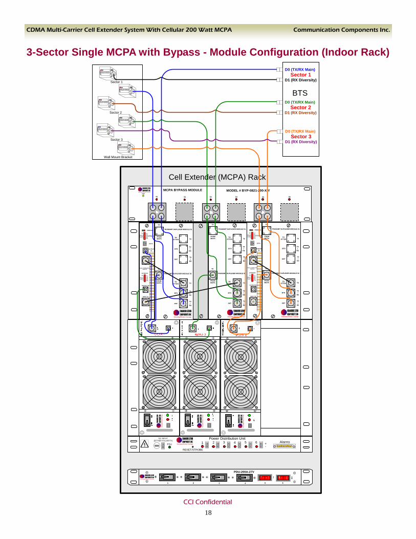
3-Sector Single MCPA with Bypass - Module Configuration (Indoor Rack) MODEL# BT-1819-NT1900 PCS BIAS-T FOR NORTEL BTS
SN
MODEL# BT-1819-NT1900 PCS BIAS-T FOR NORTEL BTS
SN
MODEL# BT-1819-NT1900 PCS BIAS-T FOR NORTEL BTS
SN
MODEL# BT-1819-NT1900 PCS BIAS-T FOR NORTEL BTS
SN
Wall Mount Bracket
Sector 1
Sector 2
Sector 3
INPUT 01
OUTPUT 01
DATA
ATTEN 01
PWR/ALM
INPUT 02
OUTPUT 02
ATTEN 02
DUAL ATTENUATOR MODULE
LOCREM1 dB2 dB4 dB8 dB
16 dB
TOTAL ATTEN 42 dB
+
LOCREM1 dB2 dB4 dB8 dB16 dB
TOTAL ATTEN 42 dB
+
TX
TX
TX/
RX
TX/
RX
FROM MCPA
TOATTEN
BTS
ANT
TRANSMIT DUPLEXER MODULE
TX
TX
TX/
RX
TX/
RX
FROM MCPA
TOATTEN
BTS
ANT
TRANSMIT DUPLEXER MODULE
BTS
Sector 1D0 (TX/RX Main)
D1 (RX Diversity)
Sector 2D0 (TX/RX Main)
D1 (RX Diversity)
Sector 3D0 (TX/RX Main)
D1 (RX Diversity)
Cell Extender (MCPA) Rack
Alarms
RESET/STROBE
Power Distribution Unit+-
654321DC INPUT
(EITHER POLARITY)
PSU
1
PDU-200A-27V
2 3 4 5 6
INPUT 01
OUTPUT 01
DATA
ATTEN 01
PWR/ALM
INPUT 02
OUTPUT 02
ATTEN 02
DUAL ATTENUATOR MODULE
LOCREM1 dB2 dB4 dB8 dB
16 dB
TOTAL ATTEN 42 dB
+
LOCREM1 dB2 dB4 dB8 dB16 dB
TOTAL ATTEN 42 dB
+
TX
TX
TX/
RX
TX/
RX
FROM MCPA
TOATTEN
BTS
ANT
TRANSMIT DUPLEXER MODULE 01
TX
TX
TX/
RX
TX/
RX
FROM MCPA
TOATTEN
BTS
ANT
TRANSMIT DUPLEXER MODULE 02
TX
TX
TX/
RX
TX/
RX
FROM MCPA
TOATTEN
BTS
ANT
TRANSMIT DUPLEXER MODULE 01
TX
TX
TX/
RX
TX/
RX
FROM MCPA
TOATTEN
BTS
ANT
TRANSMIT DUPLEXER MODULE 02
INPUT 01
OUTPUT 01
DATA
ATTEN 01
PWR/ALM
INPUT 02
OUTPUT 02
ATTEN 02
DUAL ATTENUATOR MODULE
LOCREM1 dB2 dB4 dB8 dB
16 dB
TOTAL ATTEN 42 dB
+
LOCREM1 dB2 dB4 dB8 dB16 dB
TOTAL ATTEN 42 dB
+
TX
TX
TX/
RX
TX/
RX
FROM MCPA
TOATTEN
BTS
ANT
TRANSMIT DUPLEXER MODULE 01
TX
TX
TX/
RX
TX/
RX
FROM MCPA
TOATTEN
BTS
ANT
TRANSMIT DUPLEXER MODULE 02
MCPA BYPASS MODULE
S1 S4S3S2
MODEL # BYP-0821-200-X-YPWR
S6S5
MODEL# BT-1819-NT1900 PCS BIAS-T FOR NORTEL BTS
SN
MODEL# BT-1819-NT1900 PCS BIAS-T FOR NORTEL BTS
SN
18 CCI Confidential

Communication Components Inc. CDMA Multi-Carrier Cell Extender System With Cellular 200 Watt MCPA
System Block Diagram - N+1 Redundancy
19 CCI Confidential
CCI Cell Extender Cabinet or Rack
C1
2
C1
2
MCPA
BIAS-T
BIAS-T
Dual Attenuator Module
Rx
Tx
Rx
TxTx IN
Tx OUT
Tx/Rx OUT
Tx/Rx IN
I/O DUPLEXERDC BYPASS
C1
2
C1
2
MCPA
BIAS-T
BIAS-T
Dual Attenuator Module
Rx
Tx
Rx
TxTx IN
Tx OUT
Tx/Rx OUT
Tx/Rx IN
I/O DUPLEXERDC BYPASS
Dual Attenuator Module
Rx
Tx
Rx
TxTx IN
Tx OUT
Tx/Rx OUT
Tx/Rx IN
I/O DUPLEXERDC BYPASS
C1
2
C1
2
MCPA
BIAS-T
BIAS-T
SECTOR 2
SECTOR 3
TMA
TX/RX MAIN
ANTENNA
TMA
RX DIVERSITY ANTENNA
SECTOR 1
BTS
TX + RX MAIN
RX DIVERSITY
TX + RX MAIN
RX DIVERSITY
TX + RX MAIN
RX DIVERSITY
SECTOR1
SECTOR2
SECTOR3
TMA
TX/RX MAIN
ANTENNA
TMA
RX DIVERSITY ANTENNA
TMA
TX/RX MAIN
ANTENNA
TMA
RX DIVERSITY ANTENNA
C
1234
C
123
4
SPARE MCPA
N+1 REDUNDANCY
PDU to Power Bias-T’s

Communication Components Inc. CDMA Multi-Carrier Cell Extender System With Cellular 200 Watt MCPA
3-Sector with N+1 Redundancy - Module Configuration
20 CCI Confidential
Alarms
RESET/STROBE
Power Distribution Unit+-
654321DC INPUT
(EITHER POLARITY)
PSU
MO
DEL
# R
EC-1
00A-
27V
SN:
MO
DEL#
REC
-100
A-27
VSN
:
MO
DEL#
REC
-100
A-27
V
SN:
ON1
0OFF
10
ON1
0OFF
10
BATT ON
MOD FAIL
AC PWR ON
1 432
5
60 6606060
INPUT 01
OUTPUT 01
DATA
ATTEN 01
PWR/ALM
INPUT 02
OUTPUT 02
ATTEN 02
DUAL ATTENUATOR MODULE
LOCREM
1 dB2 dB4 dB8 dB16 dB
TOTAL ATTEN 42 dB
+
LOCREM1 dB2 dB4 dB8 dB16 dB
TOTAL ATTEN 42 dB
+
TX
TX
TX/
RX
TX/
RX
FROM MCPA TO
ATTEN
BTS
ANT
TRANSMIT DUPLEXER MODULE 01
TX
TX
TX/
RX
TX/
RX
FROM MCPA TO
ATTEN
BTS
ANT
TRANSMIT DUPLEXER MODULE 02
INPUT 01
OUTPUT 01
DATA
ATTEN 01
PWR/ALM
INPUT 02
OUTPUT 02
ATTEN 02
DUAL ATTENUATOR MODULE
LOCREM1 dB2 dB4 dB8 dB
16 dB
TOTAL ATTEN 42 dB
+
LOCREM
1 dB2 dB4 dB8 dB16 dB
TOTAL ATTEN 42 dB
+
TX
TX
TX/
RX
TX/
RX
FROM MCPA TO
ATTEN
BTS
ANT
TRANSMIT DUPLEXER MODULE 01
TX
TX
TX/
RX
TX/
RX
FROM MCPA TO
ATTEN
BTS
ANT
TRANSMIT DUPLEXER MODULE 02
OU
T
IN
850 MH
z MC
PA
AC
TA
LM
ON
OFF
OU
T
IN
850 MH
z MC
PA
AC
TA
LM
ON
OFF
OU
T
IN
850 MH
z MC
PA
AC
TA
LM
ON
OFF
OU
T
IN
850 MH
z MC
PA
AC
TA
LM
ON
OFF
REDUNDANCY SW
A
CB
SPAREOUT SW SEC-A/IN OUT SW SEC-B/IN OUT SW SEC-C/IN OUT SW SPARE/IN
IN SW SEC-A/OUT IN SW SEC-B/OUT IN SW SEC-C/OUT IN SW SPARE/OUT
OUT SW SEC-A/OUT OUT SW SEC-B/OUT OUT SW SEC-C/OUT
IN SW SEC-C/ININ SW SEC-B/ININ SW SEC-A/IN
SECTOR 1 (Inputs)
SECTOR 2 (Inputs)
SECTOR 3 (Inputs)
SECTOR 1 (Outputs)
SECTOR 2 (Outputs)
SECTOR 3 (Outputs)
AC JUNCTION BOX
AC TO PPS (3-Wire)
TO BATT. POS. (1
Wire)
TO BATT. NEG. (1 Wire)
Mul
ti-W
ire A
larm
TX1/RXATX2/RXBTX1/RXATX2/RXBTX1/RXATX2/RXB
ANT AANT BANT AANT BANT AANT B

Communication Components Inc. CDMA Multi-Carrier Cell Extender System With Cellular 200 Watt MCPA
System Block Diagram - 3-Sector “Dual MCPA for Two Active Antenna” with Bypass
21 CCI Confidential
TX
Dual Attenuator Module
Rx
Tx
Rx
TxTx IN
Tx OUT
Tx/Rx OUT
Tx/Rx IN
I/O DUPLEXERDC BYPASS
Rx
Tx
Rx
TxTx IN
Tx OUT
Tx/Rx OUT
Tx/Rx IN
I/O DUPLEXERDC BYPASS
SECTOR 2
SECTOR 3
TMA
TX/RX MAIN
ANTENNA
TMA
TX/RX DIVERSITY ANTENNA
SECTOR 1
BTS
TX + RX MAIN
TX + RX DIVERSITY
TX + RX MAIN
TX + RX DIVERSITY
TX + RX MAIN
TX + RX DIVERSITY
SECTOR1SECTOR2SECTOR3
C1
2
C1
2
BYPASS
C1
2
C1
2
MCPAMCPA
TMA
TX/RX MAIN
ANTENNA
TMA
TX/RX DIVERSITY ANTENNA
C 1
2
C1
2
BYPASS
C1
2
C1
2
MCPAMCPA
TMA
TX/RX MAIN
ANTENNA
TMA
TX/RX DIVERSITY ANTENNA
C1
2
BYPASS
C 1
2
C1
2
MCPAMCPA
C1
2
BYPASS
BYPASS
BYPASS
BIAS-T
BIAS-T
BIAS-T
BIAS-T
BIAS-T
BIAS-T
PDU to Power Bias-T’s
TX
Dual Attenuator Module
Rx
Tx
Rx
TxTx IN
Tx OUT
Tx/Rx OUT
Tx/Rx IN
I/O DUPLEXERDC BYPASS
Rx
Tx
Rx
TxTx IN
Tx OUT
Tx/Rx OUT
Tx/Rx IN
I/O DUPLEXERDC BYPASS
TX
Dual Attenuator Module
Rx
Tx
Rx
TxTx IN
Tx OUT
Tx/Rx OUT
Tx/Rx IN
I/O DUPLEXERDC BYPASS
Rx
Tx
Rx
TxTx IN
Tx OUT
Tx/Rx OUT
Tx/Rx IN
I/O DUPLEXERDC BYPASS
CCI Cell Extender Cabinet or Rack
Communication Components Inc. CDMA Multi-Carrier Cell Extender System With Cellular 200 Watt MCPA
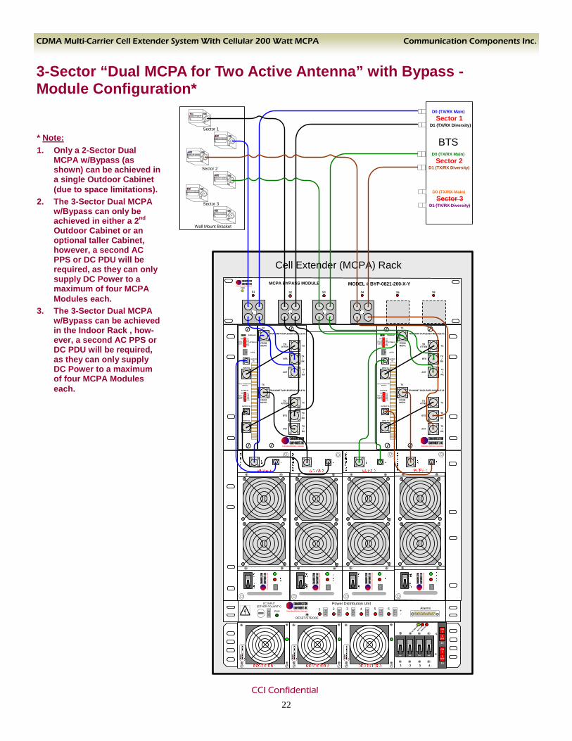
3-Sector “Dual MCPA for Two Active Antenna” with Bypass - Module Configuration*
* Note: 1. Only a 2-Sector Dual
MCPA w/Bypass (as shown) can be achieved in a single Outdoor Cabinet (due to space limitations).
2. The 3-Sector Dual MCPA w/Bypass can only be achieved in either a 2nd Outdoor Cabinet or an optional taller Cabinet, however, a second AC PPS or DC PDU will be required, as they can only supply DC Power to a maximum of four MCPA Modules each.
3. The 3-Sector Dual MCPA w/Bypass can be achieved in the Indoor Rack , how-ever, a second AC PPS or DC PDU will be required, as they can only supply DC Power to a maximum of four MCPA Modules each.
Cell Extender (MCPA) Rack
MODEL# BT-1819-NT1900 PCS BIAS-T FOR NORTEL BTS
SN
MODEL# BT-1819-NT1900 PCS BIAS-T FOR NORTEL BTS
SN
MODEL# BT-1819-NT1900 PCS BIAS-T FOR NORTEL BTS
SN
MODEL# BT-1819-NT1900 PCS BIAS-T FOR NORTEL BTS
SN
MODEL# BT-1819-NT1900 PCS BIAS-T FOR NORTEL BTS
SN
MODEL# BT-1819-NT1900 PCS BIAS-T FOR NORTEL BTS
SN
Wall Mount Bracket
Sector 1
Sector 2
Sector 3
Alarms
RESET/STROBE
Power Distribution Unit
+-
654321
DC INPUT(EITHER POLARITY)
PSU
MCPA BYPASS MODULE
SECTOR 1 SECTOR 4SECTOR 3SECTOR 2
MODEL # BYP-MCPB-200
DC INPWR BP3 BP4PWR BP1 BP2
BTS
Sector 1D0 (TX/RX Main)
D1 (TX/RX Diversity)
Sector 2D0 (TX/RX Main)
D1 (TX/RX Diversity)
Sector 3D0 (TX/RX Main)
D1 (TX/RX Diversity)
BATT O
N
MOD FAIL
AC PWR ON
1 432
5
60 6606060
ON1
0OFF
10
ON1
0OFF
10
INPUT 01
OUTPUT 01
DATA
ATTEN 01
PWR/ALM
INPUT 02
OUTPUT 02
ATTEN 02
DUAL ATTENUATOR MODULE
LOCREM1 dB2 dB4 dB8 dB
16 dB
TOTAL ATTEN 42 dB
+
LOCREM1 dB2 dB4 dB8 dB16 dB
TOTAL ATTEN 42 dB
+
TX
TX
TX/
RX
TX/
RX
FROM MCPA
TOATTEN
BTS
ANT
TRANSMIT DUPLEXER MODULE 01
TX
TX
TX/
RX
TX/
RX
FROM MCPA
TOATTEN
BTS
ANT
TRANSMIT DUPLEXER MODULE 02
MCPA BYPASS MODULE
S1 S4S3S2
MODEL # BYP-0821-200-X-YPWR
S6S5
22 CCI Confidential

Communication Components Inc. CDMA Multi-Carrier Cell Extender System With Cellular 200 Watt MCPA
47.5
24.50
22.75 26.25
Outdoor Three Sector Cabinet Mechanical Specification
♦ No HVAC Required ♦ Flexible Mounting Options:
1. Can be saddle mounted to side of BTS or other existing cabinet
2. Can be mounted on optional Base Unit as a free standing unit
♦ Low Maintenance Design
♦ All Aluminum Construction ♦ Powder Coated Finish
♦ Weatherproof Construction
Features & Benefits
♦ -1S: Single Sector ♦ -2S: Two Sector ♦ -3S: Three Sector ♦ -1A: Single Active Antenna (all carriers on one antenna) ♦ -2A: Two Active Antennas (carriers are distributed between two antennas) ♦ -4: By-Pass Option ♦ -5: Redundant Amplifier (N+1) Option ♦ -I: Indoor Rack ♦ -O: Outdoor Cabinet
Options
Ordering Information ♦ Model CE850-200MC –XS-YA-Z-*S Where: X = “Number” of Sectors Required (1, 2 or 3) Y = “Number” of Active Antennas per Sector Required (1 or 2) Z = “4” for Bypass Option, or “5” for Redundant Amplifier Option * = “I” for Indoor Rack Mounted, or “O” for Outdoor Cabinet Mounted - 200W CDMA Cell Extender
C o m m u n i c a t i o n C o m p o n e n t s I n c .
23 Tel: 201-342-3338 Fax: 201-342-3339
CCI Confidential
Communication Components Inc. CDMA Multi-Carrier Cell Extender System With Cellular 200 Watt MCPA
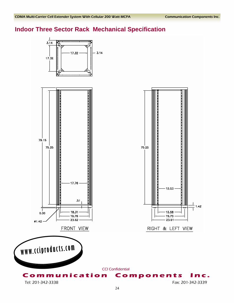
Indoor Three Sector Rack Mechanical Specification
w w w. c c i p r o d u c t s . c o m
C o m m u n i c a t i o n C o m p o n e n t s I n c .
24 Tel: 201-342-3338 Fax: 201-342-3339
CCI Confidential