Embed Size (px)
Citation preview

8/6/2019 CCNPv6 Route 1 Introduction
http://slidepdf.com/reader/full/ccnpv6-route-1-introduction 1/49
© 2007 – 2010, Cisco Systems, Inc. All r ights reserved. Cisco Public
ROUTE v6 Chapter 11
Chapter 1:Routing Services
CCNP ROUTE: Implementing IP Routing

8/6/2019 CCNPv6 Route 1 Introduction
http://slidepdf.com/reader/full/ccnpv6-route-1-introduction 2/49
Chapter 12 © 2007 – 2010, Cisco Systems, Inc. All r ights reserved. Cisco Public
Chapter 1 Objectives
Describe common enterprise traffic requirements andnetwork design models.
Describe how to create a plan for implementing routingservices in an enterprise network.
Review the fundamentals of routing and compare variousrouting protocols.

8/6/2019 CCNPv6 Route 1 Introduction
http://slidepdf.com/reader/full/ccnpv6-route-1-introduction 3/49
Chapter 13 © 2007 – 2010, Cisco Systems, Inc. All r ights reserved. Cisco Public
ComplexEnterpriseNetworkFrameworks,Architectures,and Models

8/6/2019 CCNPv6 Route 1 Introduction
http://slidepdf.com/reader/full/ccnpv6-route-1-introduction 4/49Chapter 14 © 2007 – 2010, Cisco Systems, Inc. All r ights reserved. Cisco Public
Traffic Conditions in a Converged Network
Modern networks must support various types of traffic:
• Voice and video traffic
• Voice applications traffic
• Mission-critical traffic
• Transactional traffic
• Network management traffic
• Routing protocol traffic
This mix of traffic greatly impacts the network requirementssuch as security and performance.
To help enterprises, Cisco has developed the IntelligentInformation Network (IIN).

8/6/2019 CCNPv6 Route 1 Introduction
http://slidepdf.com/reader/full/ccnpv6-route-1-introduction 5/49Chapter 1
5 © 2007 – 2010, Cisco Systems, Inc. All r ights reserved. Cisco Public
Cisco Intelligent Information Network
The Intelligent Information Network (IIN):
• Integrates networked resources and information assets.
• Extends intelligence across multiple products and infrastructure
layers.
• Actively participates in the delivery of services and applications.
The IIN technology vision consists of 3 three phases in
which functionality can be added to the infrastructure asrequired:
• Integrated transport
• Integrated services• Integrated applications
8/6/2019 CCNPv6 Route 1 Introduction
http://slidepdf.com/reader/full/ccnpv6-route-1-introduction 6/49Chapter 1
6 © 2007 – 2010, Cisco Systems, Inc. All r ights reserved. Cisco Public
3 Phases of the IIN
Phase 1: Integrated transport
• Integrates data, voice, and video transport into a single, standards-based,modular network simplifying network management and generating enterprise-
wide efficiencies. Phase 2: Integrated services
• Integrated services help to unify common elements, such as storage and datacenter server capacity.
• IT resources can now be pooled and shared, or virtualized, to address thechanging needs of the organization.
• Business continuity is also enhanced in the event of a local systems failurebecause shared resources across the IIN can provide needed services.
Phase 3: Integrated applications
• This phase focuses on making the network application-aware so that it can
optimize application performance and more efficiently deliver networkedapplications to users.

8/6/2019 CCNPv6 Route 1 Introduction
http://slidepdf.com/reader/full/ccnpv6-route-1-introduction 7/49Chapter 1
7 © 2007 – 2010, Cisco Systems, Inc. All r ights reserved. Cisco Public
Cisco SONA Framework Layers
The SONA framework outlines three layers:
Application Layer:
Interactive Services Layer:
Network Infrastructure Layer:

8/6/2019 CCNPv6 Route 1 Introduction
http://slidepdf.com/reader/full/ccnpv6-route-1-introduction 8/49
Chapter 18 © 2007 – 2010, Cisco Systems, Inc. All r ights reserved. Cisco Public
Cisco Enterprise Architecture
The places in the network in the SONA Network Infrastructure Layerhave been identified as follows:

8/6/2019 CCNPv6 Route 1 Introduction
http://slidepdf.com/reader/full/ccnpv6-route-1-introduction 9/49
Chapter 19 © 2007 – 2010, Cisco Systems, Inc. All r ights reserved. Cisco Public
The Cisco Enterprise Architecture

8/6/2019 CCNPv6 Route 1 Introduction
http://slidepdf.com/reader/full/ccnpv6-route-1-introduction 10/49
Chapter 110 © 2007 – 2010, Cisco Systems, Inc. All r ights reserved. Cisco Public
Cisco Hierarchical Network Model
The three-layer hierarchical model is used extensively innetwork design.
The hierarchical model consists of the:
• Access layer
• Distribution layer
• Core layer
It provides a modular framework that allows design flexibilityand facilitates implementation and troubleshooting.
• The hierarchical model is useful for smaller networks, but does not
scale well to today’s larger, more complex networks.

8/6/2019 CCNPv6 Route 1 Introduction
http://slidepdf.com/reader/full/ccnpv6-route-1-introduction 11/49
Chapter 111 © 2007 – 2010, Cisco Systems, Inc. All r ights reserved. Cisco Public
Hierarchical Campus Model

8/6/2019 CCNPv6 Route 1 Introduction
http://slidepdf.com/reader/full/ccnpv6-route-1-introduction 12/49
Chapter 112 © 2007 – 2010, Cisco Systems, Inc. All r ights reserved. Cisco Public
Enterprise Composite Network Model
The Enterprise Composite Network Model divides thenetwork into three functional areas:
Enterprise Campus Enterprise Edge Service
Provider Edge

8/6/2019 CCNPv6 Route 1 Introduction
http://slidepdf.com/reader/full/ccnpv6-route-1-introduction 13/49
Chapter 113 © 2007 – 2010, Cisco Systems, Inc. All r ights reserved. Cisco Public
Enterprise Composite Network Model
Building Access
Building Distribution
Core (Campus backbone)
Server Farm
Management
EdgeDistribution
E-Commerce ISP A
Corporate Internet
Remote AccessVPN
WAN Frame Relay/ ATM
PSTN
ISP B
Enterprise Campus Enterprise Edge ServiceProvider Edge

8/6/2019 CCNPv6 Route 1 Introduction
http://slidepdf.com/reader/full/ccnpv6-route-1-introduction 14/49
Chapter 114 © 2007 – 2010, Cisco Systems, Inc. All r ights reserved. Cisco Public
Modules in the Enterprise Campus
Building Access
Building Distribution
Core (Campus backbone)
Server Farm
Management
EdgeDistribution
E-Commerce ISP A
Corporate Internet
Remote AccessVPN
WAN Frame Relay/ ATM
PSTN
ISP B
Enterprise Campus Enterprise Edge ServiceProvider Edge

8/6/2019 CCNPv6 Route 1 Introduction
http://slidepdf.com/reader/full/ccnpv6-route-1-introduction 15/49
Chapter 115 © 2007 – 2010, Cisco Systems, Inc. All r ights reserved. Cisco Public
Modules in the Enterprise Edge
Building Access
Building Distribution
Core (Campus backbone)
Server Farm
Management
EdgeDistribution
E-Commerce ISP A
Corporate Internet
Remote AccessVPN
WAN Frame Relay/ ATM
PSTN
ISP B
Enterprise Campus Enterprise Edge ServiceProvider Edge
8/6/2019 CCNPv6 Route 1 Introduction
http://slidepdf.com/reader/full/ccnpv6-route-1-introduction 16/49
Chapter 116 © 2007 – 2010, Cisco Systems, Inc. All r ights reserved. Cisco Public
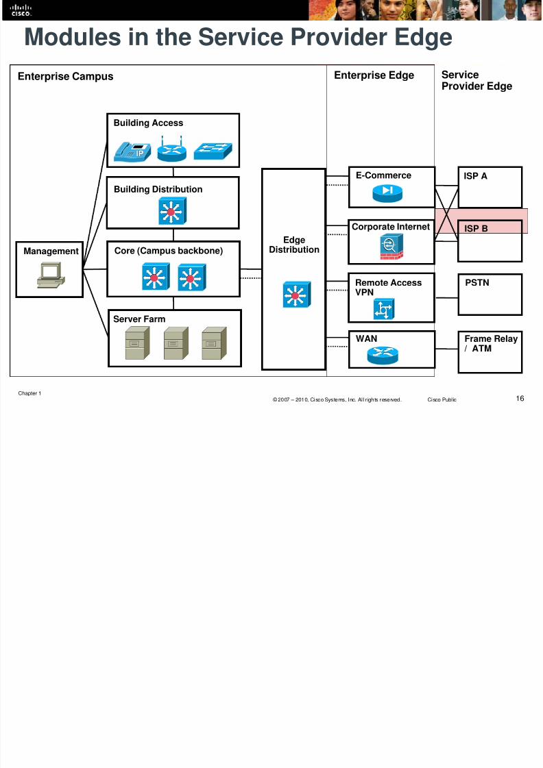
Modules in the Service Provider Edge
Building Access
Building Distribution
Core (Campus backbone)
Server Farm
Management
EdgeDistribution
E-Commerce ISP A
Corporate Internet
Remote AccessVPN
WAN Frame Relay/ ATM
PSTN
ISP B
Enterprise Campus Enterprise Edge ServiceProvider Edge

8/6/2019 CCNPv6 Route 1 Introduction
http://slidepdf.com/reader/full/ccnpv6-route-1-introduction 17/49
Chapter 117 © 2007 – 2010, Cisco Systems, Inc. All r ights reserved. Cisco Public
Cisco Lifecycle Services (PPDIOO) Model
The Cisco Lifecycle Services approach defines six phases in the networklifecycle and is referred to as the PPDIOO model:
Prepare OptimizePlan Design Implement Operate

8/6/2019 CCNPv6 Route 1 Introduction
http://slidepdf.com/reader/full/ccnpv6-route-1-introduction 18/49
Chapter 118 © 2007 – 2010, Cisco Systems, Inc. All r ights reserved. Cisco Public
Implementation Task List (sample)
Step No. Task
1. Connect to the router
2. Verify the current installation and create backup file
3. Change IOS version (on all routers)
4. Update IP address configuration (on distribution routers)
5. Configure EIGRP routing protocol
6. Verify configuration and record the results

8/6/2019 CCNPv6 Route 1 Introduction
http://slidepdf.com/reader/full/ccnpv6-route-1-introduction 19/49
Chapter 119 © 2007 – 2010, Cisco Systems, Inc. All r ights reserved. Cisco Public
IP RoutingOverview

8/6/2019 CCNPv6 Route 1 Introduction
http://slidepdf.com/reader/full/ccnpv6-route-1-introduction 20/49
Chapter 120 © 2007 – 2010, Cisco Systems, Inc. All r ights reserved. Cisco Public
Routing
This section addresses the ways in which routers learnabout networks and how routers can incorporate static anddynamic routes.
A router can be made aware of remote networks in twoways:
• An administrator can manually configure the information (static
routing)• The router can learn from other routers (dynamic routing).
A routing table can contain both static and dynamically
recognized routes.

8/6/2019 CCNPv6 Route 1 Introduction
http://slidepdf.com/reader/full/ccnpv6-route-1-introduction 21/49
Chapter 121 © 2007 – 2010, Cisco Systems, Inc. All r ights reserved. Cisco Public
Static Routes
A static route can be used in the following circumstances:
• To have absolute control of routes used by the router.
• When a backup to a dynamically recognized route is necessary.
• When it is undesirable to have dynamic routing updates forwardedacross slow bandwidth links.
• To reach a stub network.

8/6/2019 CCNPv6 Route 1 Introduction
http://slidepdf.com/reader/full/ccnpv6-route-1-introduction 22/49
Chapter 122 © 2007 – 2010, Cisco Systems, Inc. All r ights reserved. Cisco Public
Static Routing
Configure a static route with the ip route command.
Router(config)#
ip route prefix mask address interface dhcp distance name
next-hop-name permanent track number tag tag
Parameter Description
prefix mask The IP network and subnet mask for the remote network to be entered into the IP routing table.
address The IP address of the next hop that can be used to reach the destination network.
interface The local router outbound interface to be used to reach the destination network.
dhcp(Optional) Enables a Dynamic Host Configuration Protocol (DHCP) server to assign a static route toa default gateway (option 3).
distance (Optional) The administrative distance to be assigned to this route.
name next-hop-name
(Optional) Applies a name to the specified route.
permanent(Optional) Specifies that the route will not be removed from the routing table even if the interfaceassociated with the route goes down.
track number (Optional) Associates a track object with this route. Valid values for the number argument range
from 1 to 500.tag tag (Optional) A value that can be used as a match value in route maps.

8/6/2019 CCNPv6 Route 1 Introduction
http://slidepdf.com/reader/full/ccnpv6-route-1-introduction 23/49
Chapter 123 © 2007 – 2010, Cisco Systems, Inc. All r ights reserved. Cisco Public
Configuring a Default Static Route
R2 is configured with a static route to the R1 LAN and a default staticroute to the Internet.
R1 is configured with a default static route.
R1(config)# ip route 0.0.0.0 0.0.0.0 10.1.1.1
R1(config)# exit
R1# show ip route<output omitted>
Gateway of last resort is not set
C 172.16.1.0 is directly connected, FastEthernet0/0
C 10.1.1.0 is directly connected, Serial0/0/0
S* 0.0.0.0/0 [1/0] via 10.1.1.1
R1#
R2(config)# ip route 172.16.1.0 255.255.255.0 S0/0/0
R2(config)# ip route 0.0.0.0 0.0.0.0 192.168.1.1
Internet
S0/0/0S0/0/0
Fa0/0Fa0/0
10.1.1.210.1.1.1
192.168.1.2 192.168.1.1
S0/0/1
R1 R2
172.16.1.0 /24 10.2.0.0 /16

8/6/2019 CCNPv6 Route 1 Introduction
http://slidepdf.com/reader/full/ccnpv6-route-1-introduction 24/49
Chapter 124 © 2007 – 2010, Cisco Systems, Inc. All r ights reserved. Cisco Public
Dynamic Routing
Dynamic routing (RIPv1, RIPv2, EIGRP, OSPF, and IS-IS) allows thenetwork to adjust to changes in the topology automatically,without administrator involvement.
The information exchanged by routers includes the metricor cost to each destination (this value is sometimes calledthe distance).
• Different routing protocols base their metric on differentmeasurements, including hop count, interface speed, or more-complex metrics.

8/6/2019 CCNPv6 Route 1 Introduction
http://slidepdf.com/reader/full/ccnpv6-route-1-introduction 25/49
Chapter 125 © 2007 – 2010, Cisco Systems, Inc. All r ights reserved. Cisco Public
On-Demand Routing
Static routes must be manually configured and updatedwhen the network topology changes.
Dynamic routing protocols use network bandwidth and
router resources.
• Resource usage of dynamic routing can be considerable.
A third option is to use the Cisco On-Demand Routing
(ODR) feature.• ODR uses minimal overhead compared to a dynamic routing protocol
and requires less manual configuration than static routes.

8/6/2019 CCNPv6 Route 1 Introduction
http://slidepdf.com/reader/full/ccnpv6-route-1-introduction 26/49
Chapter 126 © 2007 – 2010, Cisco Systems, Inc. All r ights reserved. Cisco Public
ODR
ODR is applicable in a hub-and-spoke topology only.
ODR works with the Cisco Discovery Protocol (CDP) tocarry network information between spokes and hub router.
The hub router sends a default route to the spokes thatpoints back to itself and installs the stub networks reportedby ODR in its routing table.
• The hub router can then be configured to redistribute the ODRlearned routes into a dynamic routing protocol.

8/6/2019 CCNPv6 Route 1 Introduction
http://slidepdf.com/reader/full/ccnpv6-route-1-introduction 27/49
Chapter 127 © 2007 – 2010, Cisco Systems, Inc. All r ights reserved. Cisco Public
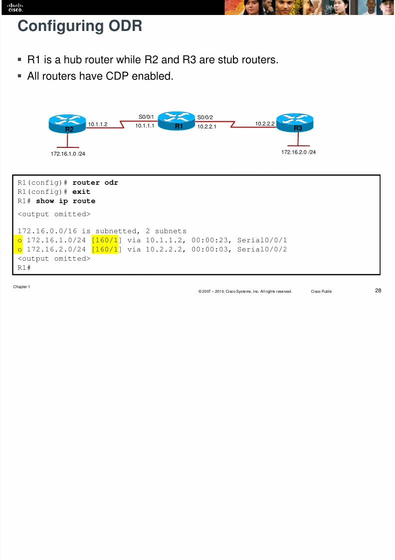
Configuring ODR
ODR is configured:
• On all routers, CDP must be enabled.
• On the hub router using the router odr global config command.
• On the stub routers, no IP routing protocol can be configured.
ODR learned routes appear in the hub router routing tablewith an entry of “o” and an administrative distance of 160.
• On each spoke router, the routing table contains only its connectednetworks and a static default route injected by ODR from the hub.
8/6/2019 CCNPv6 Route 1 Introduction
http://slidepdf.com/reader/full/ccnpv6-route-1-introduction 28/49
Chapter 128 © 2007 – 2010, Cisco Systems, Inc. All r ights reserved. Cisco Public
Configuring ODR
R1 is a hub router while R2 and R3 are stub routers.
All routers have CDP enabled.
R1(config)# router odr
R1(config)# exit
R1# show ip route
<output omitted>
172.16.0.0/16 is subnetted, 2 subnets
o 172.16.1.0/24 [160/1] via 10.1.1.2, 00:00:23, Serial0/0/1
o 172.16.2.0/24 [160/1] via 10.2.2.2, 00:00:03, Serial0/0/2
<output omitted>
R1#
S0/0/1
10.1.1.2
S0/0/2
R2 R1
172.16.1.0 /24
R3
172.16.2.0 /24
10.2.2.210.2.2.110.1.1.1
O

8/6/2019 CCNPv6 Route 1 Introduction
http://slidepdf.com/reader/full/ccnpv6-route-1-introduction 29/49
Chapter 129 © 2007 – 2010, Cisco Systems, Inc. All r ights reserved. Cisco Public
Additional ODR commands.
ODR can also be tuned with optional commands, including:
• a distribute list to filter routing updates
• timers basic router configuration command to adjust ODR timers
• cdp timer global configuration command to adjust the timers andimprove convergence time (default is every 60 seconds).
Di V V Li k S

8/6/2019 CCNPv6 Route 1 Introduction
http://slidepdf.com/reader/full/ccnpv6-route-1-introduction 30/49
Chapter 130 © 2007 – 2010, Cisco Systems, Inc. All r ights reserved. Cisco Public
Distance Vector Versus Link-State
Distance vector:
• All the routers periodically send their routing tables (or a portion oftheir tables) to only their neighboring routers.
• Routers use the received information to determine whether anychanges need to be made to their own routing table.
Link-state routing protocol:
• Each router sends the state of its own interfaces (links) to all otherrouters in an area only when there is a change.
• Each router uses the received information to recalculate the best pathto each network and then saves this information in its routing table.
Cl f l V Cl l R ti
8/6/2019 CCNPv6 Route 1 Introduction
http://slidepdf.com/reader/full/ccnpv6-route-1-introduction 31/49
Chapter 131 © 2007 – 2010, Cisco Systems, Inc. All r ights reserved. Cisco Public
Classful Versus Classless Routing
Classful Routing Protocol:
• Does not support VLSM.
• Routing updates sent do not include the subnet mask.
• Subnets are not advertised to a different major network.
• Discontiguous subnets are not visible to each other.
• RIP Version 1 (RIPv1) is a classful routing protocol.
Classless Routing Protocol:• Supports VLSM.
• Routing updates sent include the subnet mask.
• Subnets are advertised to a different major network.
• Discontiguous subnets are visible to each other.
• RIPv2, EIGRP, OSPF, IS-IS, and BGP are classless routing protocols.
Di ti S b t Cl f l R ti
8/6/2019 CCNPv6 Route 1 Introduction
http://slidepdf.com/reader/full/ccnpv6-route-1-introduction 32/49
Chapter 132 © 2007 – 2010, Cisco Systems, Inc. All r ights reserved. Cisco Public
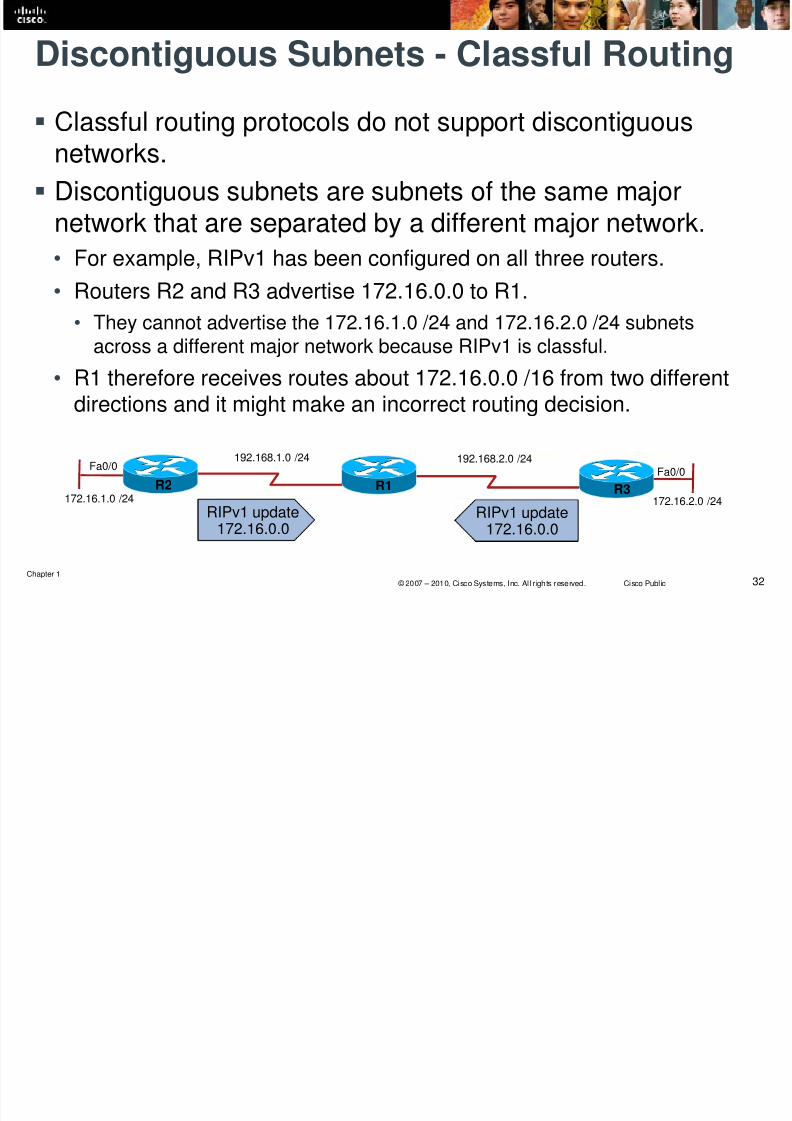
Discontiguous Subnets - Classful Routing
Classful routing protocols do not support discontiguousnetworks.
Discontiguous subnets are subnets of the same major
network that are separated by a different major network.• For example, RIPv1 has been configured on all three routers.
• Routers R2 and R3 advertise 172.16.0.0 to R1.
• They cannot advertise the 172.16.1.0 /24 and 172.16.2.0 /24 subnetsacross a different major network because RIPv1 is classful.
• R1 therefore receives routes about 172.16.0.0 /16 from two differentdirections and it might make an incorrect routing decision.
Fa0/0
R2 R1172.16.1.0 /24
R3
Fa0/0
172.16.2.0 /24
192.168.2.0 /24192.168.1.0 /24
RIPv1 update
172.16.0.0
RIPv1 update
172.16.0.0
Di ti S b t Cl l R ti

8/6/2019 CCNPv6 Route 1 Introduction
http://slidepdf.com/reader/full/ccnpv6-route-1-introduction 33/49
Chapter 133 © 2007 – 2010, Cisco Systems, Inc. All r ights reserved. Cisco Public
Discontiguous Subnets - Classless Routing
Classless routing protocols support discontiguous networks.
• For example, RIPv2 has been configured on all three routers.
• Because of RIPv2, routers R2 and R3 can now advertise the
172.16.1.0 /24 and 172.16.2.0 /24 subnets across a different majornetwork.
• R1 therefore receives routes with valid subnet information and cannow make a correct routing decision.
Fa0/0
R2 R1172.16.1.0 /24
R3
Fa0/0
172.16.2.0 /24
192.168.2.0 /24192.168.1.0 /24
RIPv2 update
172.16.1.0/24
RIPv2 update
172.16.2.0/24
R1 Routing Table:
172.16.1.0/24
172.16.2.0/24
ip classless Command

8/6/2019 CCNPv6 Route 1 Introduction
http://slidepdf.com/reader/full/ccnpv6-route-1-introduction 34/49
Chapter 134 © 2007 – 2010, Cisco Systems, Inc. All r ights reserved. Cisco Public
ip classless Command
The behavior of a classful routing protocol changes whenthe ip classless global config command is used.
Classful protocols assume that if the router knows some of
the subnets of a classful network (e.g. 10.0.0.0), then itmust know all that network’s existing subnets.
• If a packet arrives for an unknown destination on the 10.0.0.0 subnet
and:• ip classless is not enabled, the packet is dropped.
• ip classless is enabled, then the router will follow the best supernet
route or the default route.
Since IOS release 12.0, ip classless is enabled by default and
should not be disabled.
Automatic Route Summarization
8/6/2019 CCNPv6 Route 1 Introduction
http://slidepdf.com/reader/full/ccnpv6-route-1-introduction 35/49
Chapter 135 © 2007 – 2010, Cisco Systems, Inc. All r ights reserved. Cisco Public
Automatic Route Summarization
Classful routing automatically summarize to the classfulnetwork boundary at major network boundaries.
Classless routing protocols either do not automatically
summarize or automatically summarize but this feature canbe disabled.
• OSPF or IS-IS do not support automatic network summarization.
• RIPv2 and EIGRP perform automatic network summarization tomaintain backward compatibility with RIPv1 and IGRP.
• However, automatic summarization can be disabled in RIPv2 andEIGRP by using the no auto-summary router config command.
Characteristics of Routing Protocols

8/6/2019 CCNPv6 Route 1 Introduction
http://slidepdf.com/reader/full/ccnpv6-route-1-introduction 36/49
Chapter 136 © 2007 – 2010, Cisco Systems, Inc. All r ights reserved. Cisco Public
Characteristics of Routing Protocols
Characteristics RIPv1 RIPv2 EIGRP IS-IS OSPF BGP
Distance vector Link-state
Classless VLSM support
Automatic routesummarization
(can be disabledusing no auto-
summary)
(can be disabled
using no auto-summary)
Manual routesummarization
Hierarchicaltopology required
Size of network Small Small Large Large Large Very large
Metric Hops HopsComposite
metricMetric Cost Path attributes
Convergence time Slow Slow Very fast Fast Fast Slow
Routing Table Criteria
8/6/2019 CCNPv6 Route 1 Introduction
http://slidepdf.com/reader/full/ccnpv6-route-1-introduction 37/49
Chapter 137 © 2007 – 2010, Cisco Systems, Inc. All r ights reserved. Cisco Public
Routing Table Criteria
The best route selected from various routing protocols for aspecific destination is chosen by considering the followingfour criteria:
• Valid next-hop IP address.
• Administrative distance
• Metric
• Prefix
Administrative Distance

8/6/2019 CCNPv6 Route 1 Introduction
http://slidepdf.com/reader/full/ccnpv6-route-1-introduction 38/49
Chapter 138 © 2007 – 2010, Cisco Systems, Inc. All r ights reserved. Cisco Public
Administrative Distance
Cisco routers use a value called administrative distance toselect the best path when they learn of two or more routesto the same destination with the same prefix from different
routing protocols. Administrative distance rates a routing protocol’sbelievability .
Cisco has assigned a default administrative distance valueto each routing protocol supported on its routers.
• Each routing protocol is prioritized in the order of most to least
believable.
Administrative Distances

8/6/2019 CCNPv6 Route 1 Introduction
http://slidepdf.com/reader/full/ccnpv6-route-1-introduction 39/49
Chapter 139 © 2007 – 2010, Cisco Systems, Inc. All r ights reserved. Cisco Public
Administrative Distances
Route Source Default Distance Routing Table Entry
Connected interface 0 C
Static route out an interface 0 S
Static route to a next-hop address 1 S
EIGRP summary route 5 D
External BGP 20 B
Internal EIGRP 90 D
IGRP 100 IOSPF 110 O
IS-IS 115 i
RIPv1, RIPv2 120 R
Exterior Gateway Protocol (EGP) 140 E
ODR 160 O
External EIGRP 170 D EX
Internal BGP 200 B
Unknown 255
Floating Static Route

8/6/2019 CCNPv6 Route 1 Introduction
http://slidepdf.com/reader/full/ccnpv6-route-1-introduction 40/49
Chapter 140 © 2007 – 2010, Cisco Systems, Inc. All r ights reserved. Cisco Public
Floating Static Route
Routers believe static routes over any dynamically learnedroute.
To change this default behavior and make a static route
appear in the routing table only when the primary routegoes away, create a floating static route.
• The administrative distance of the static route is configured to be
higher than the administrative distance of the primary route and it“floats” above the primary route, until the primary route fails.
To configure a static route use the ip route command
with the distance parameter.
Configuring a Floating Static Route

8/6/2019 CCNPv6 Route 1 Introduction
http://slidepdf.com/reader/full/ccnpv6-route-1-introduction 41/49
Chapter 141 © 2007 – 2010, Cisco Systems, Inc. All r ights reserved. Cisco Public
Configuring a Floating Static Route
Create floating static routes on R1 and R2 that floats above the EIGRPlearned routes.
R1(config)# ip route 10.0.0.0 255.0.0.0 172.16.1.2 100
R1(config)# router eigrp 1
R1(config-router)# network 172.17.0.0R1(config-router)# network 192.168.1.0
Internet
Fa0/0Fa0/0
192.168.1.0 /24
Backup link
R1 R2
172.17.0.0 /16 10.0.0.0 /8
EIGRP 1Primary link
172.16.1.1 172.16.1.2
R2(config)# ip route 172.17.0.0 255.255.0.0 172.16.1.1 100
R2(config)# router eigrp 1
R2(config-router)# network 10.0.0.0
R2(config-router)# network 192.168.1.0
Routing Within the ECNM

8/6/2019 CCNPv6 Route 1 Introduction
http://slidepdf.com/reader/full/ccnpv6-route-1-introduction 42/49
Chapter 142 © 2007 – 2010, Cisco Systems, Inc. All r ights reserved. Cisco Public
Routing Within the ECNM
Routing protocols are an integral part of any network.• When designing a network routing protocol, selection and planning
are among the design decisions to be made.
Although the best practice is to use one IP routing protocolthroughout the enterprise if possible, in some cases multiplerouting protocols might be required.
Suggested Routing Protocols Used

8/6/2019 CCNPv6 Route 1 Introduction
http://slidepdf.com/reader/full/ccnpv6-route-1-introduction 43/49
Chapter 143 © 2007 – 2010, Cisco Systems, Inc. All r ights reserved. Cisco Public
Suggested Routing Protocols Used
Building Access
Building Distribution
Core (Campus backbone)
Server Farm
EdgeDistribution
RIPv2, OSPF, EIGRP, Static routes
OSPF, EIGRP, IS-IS and BGP
Between Building Access andBuilding Distribution:
Between Building Distribution
and Core:
Routing Within the ECNM

8/6/2019 CCNPv6 Route 1 Introduction
http://slidepdf.com/reader/full/ccnpv6-route-1-introduction 44/49
Chapter 144 © 2007 – 2010, Cisco Systems, Inc. All r ights reserved. Cisco Public
Routing Within the ECNM
The Enterprise Composite Network Model can assist indetermining where each routing protocol is implemented,where the boundaries between protocols are, and how
traffic flows between them will be managed.
Chapter 1 Summary

8/6/2019 CCNPv6 Route 1 Introduction
http://slidepdf.com/reader/full/ccnpv6-route-1-introduction 45/49
Chapter 145 © 2007 – 2010, Cisco Systems, Inc. All r ights reserved. Cisco Public
Chapter 1 Summary
Traffic in converged networks includes voice and video, voice applications,mission-critical, transactional, routing protocol, and network management.
The three phases of the Cisco IIN: integrated transport, integrated services, andintegrated applications.
The three layers of the Cisco SONA architectural framework: networkedinfrastructure, interactive services, application.
The components of the Cisco Enterprise Architecture for integration of the entire
network: campus, data center, branches, teleworkers, and WAN.
The traditional hierarchical network model with its three layers: core, distribution,and access.
The Cisco Enterprise Composite Network Model with its three functional areasand their associated modules:
• Enterprise Campus: Building, Building Distribution, Core, Edge Distribution, Server Farm,Management
• Enterprise Edge: E-commerce, Corporate Internet, VPN and Remote Access, WAN
• Service Provider Edge: ISP, PSTN, Frame Relay/ATM.
Chapter 1 Summary (continued)

8/6/2019 CCNPv6 Route 1 Introduction
http://slidepdf.com/reader/full/ccnpv6-route-1-introduction 46/49
Chapter 146 © 2007 – 2010, Cisco Systems, Inc. All r ights reserved. Cisco Public
Chapter 1 Summary (continued)
The two approaches to implementing changes to a network: using anad-hoc approach or using a structured approach.
Four models used in IT services lifecycles: Cisco Lifecycle Services(PPDIOO), ITIL, FCAPS, and TMN.
Creating an implementation plan, as part of the network Design phase,that includes:
• Network information
• Tools required• Resources required
• Implementation plan tasks
• Verification tasks
• Performance measurement and results}
Chapter 1 Summary (continued)

8/6/2019 CCNPv6 Route 1 Introduction
http://slidepdf.com/reader/full/ccnpv6-route-1-introduction 47/49
Chapter 147 © 2007 – 2010, Cisco Systems, Inc. All r ights reserved. Cisco Public
p y ( )
Static routing characteristics and configuration. Characteristics and configuration of ODR, which uses CDP to carry network information between spoke
(stub) routers and the hub router.
Dynamic routing protocol characteristics, including:
• The metric, a value (such as path length) that routing protocols use to measure paths to a destination.
• Configuration, using the router protocol global configuration command.
• Distance vector routing, in which all the routers periodically send their routing tables (or a portion of their tables) toonly their neighboring routers.
• Link-state routing, in which each of the routers sends the state of its own interfaces (its links) to all other routers (or toall routers in a part of the network, known as an area) only when there is a change.
• Hybrid routing, in which routers send only changed information when there is a change (similar to link-state protocols)but only to neighboring routers (similar to distance vector protocols).
• Classful routing protocol updates, which do not include the subnet mask. Classful protocols do not support VLSM ordiscontiguous subnets and must automatically summarize across the network boundary to the classful address.
• Classless routing protocol updates, which do include the subnet mask. Classless protocols do support VLSM and
discontiguous subnets, and do not have to summarize automatically across network boundaries. The process that Cisco routers use to populate their routing tables includes a valid next-hop IP
address, Administrative distance, metric, and prefix.
Chapter 1 Labs

8/6/2019 CCNPv6 Route 1 Introduction
http://slidepdf.com/reader/full/ccnpv6-route-1-introduction 48/49
Chapter 148 © 2007 – 2010, Cisco Systems, Inc. All r ights reserved. Cisco Public
Lab 1-1 Tcl Script Reference and Demonstration
p

8/6/2019 CCNPv6 Route 1 Introduction
http://slidepdf.com/reader/full/ccnpv6-route-1-introduction 49/49
Chapter 149 © 2007 – 2010, Cisco Systems, Inc. All r ights reserved. Cisco Public


