Embed Size (px)
Citation preview
800 East 96th StreetIndianapolis, IN 46240 USA
Cisco Press
CCNP BCMSN Portable Command Guide
Scott Empson
ii
CCNP BCMSN Portable Command GuideScott Empson
Copyright © 2007 Cisco Systems, Inc.
Published by:Cisco Press800 East 96th Street Indianapolis, IN 46240 USA
All rights reserved. No part of this book may be reproduced or transmitted in any form or by any means, electronic or mechanical, including photocopying, recording, or by any information storage and retrieval system, without written permission from the publisher, except for the inclusion of brief quotations in a review.
ISBN-10: 1-58720-188-7
ISBN-13: 978-1-58720-188-2
Printed in the United States of America 1 2 3 4 5 6 7 8 9 0
First Printing June 2007
Library of Congress Cataloging-in-Publication Data
Empson, Scott.
CCNP BCMSN portable command guide / Scott Empson.
p. cm.
ISBN 978-1-58720-188-2 (pbk.)
1. Computer networks--Problems, exercises, etc. 2. Computer networks--Examinations--Study guides. 3. Packet switching (Data transmission)--Examinations--Study guides. I. Title.
TK5105.8.C57E57 2007
004.6'6--dc22
2007019367
Warning and DisclaimerThis book is designed to provide information about the Certified Cisco Networking Professional (CCNP) 642-812 Building Cisco Multilayer Switched Networks (BCMSN) exam and the commands needed at this level of network administration. Every effort has been made to make this book as complete and as accurate as possible, but no warranty or fitness is implied.
The information is provided on an “as is” basis. The author, Cisco Press, and Cisco Systems, Inc. shall have neither liability nor responsibility to any person or entity with respect to any loss or damages arising from the information contained in this book or from the use of the discs or programs that may accompany it.
The opinions expressed in this book belong to the author and are not necessarily those of Cisco Systems, Inc.

iii
Trademark AcknowledgmentsAll terms mentioned in this book that are known to be trademarks or service marks have been appropriately capitalized. Cisco Press or Cisco Systems, Inc. cannot attest to the accuracy of this information. Use of a term in this book should not be regarded as affecting the validity of any trademark or service mark.
Feedback InformationAt Cisco Press, our goal is to create in-depth technical books of the highest quality and value. Each book is crafted with care and precision, undergoing rigorous development that involves the unique expertise of members from the professional technical community.
Readers’ feedback is a natural continuation of this process. If you have any comments regarding how we could improve the quality of this book, or otherwise alter it to better suit your needs, you can contact us through email at [email protected]. Please make sure to include the book title and ISBN in your message.
We greatly appreciate your assistance.
Corporate and Government SalesCisco Press offers excellent discounts on this book when ordered in quantity for bulk purchases or special sales.
For more information please contact: U.S. Corporate and Government Sales 1-800-382-3419 [email protected]
For sales outside the U.S. please contact: International Sales [email protected]
Publisher: Paul Boger
Associate Publisher: David Dusthimer
Executive Editor: Mary Beth Ray
Cisco Representative: Anthony Wolfenden
Cisco Press Program Manager: Jeff Brady
Managing Editor: Patrick Kanouse
Senior Development Editor: Christopher Cleveland
Project Editor: Seth Kerney
Copy Editor: Keith Cline
Proofreader: Water Crest Publishing, Inc.
Technical Editors: Tami Day-Orsatti and David Kotfila
Team Coordinator: Vanessa Evans
Book Designer: Louisa Adair
Composition: Mark Shirar
iv
About the AuthorScott Empson is currently the assistant program chair of the bachelor of applied information systems technology degree program at the Northern Alberta Institute of Technology in Edmonton, Alberta, Canada, where he teaches Cisco routing, switching, and network design courses in a variety of different programs—certificate, diploma, and applied degree—at the post-secondary level. Scott is also the program coordinator of the Cisco Networking Academy Program at NAIT, a Regional Academy covering central and northern Alberta. He has earned three undergraduate degrees: a bachelor of arts, with a major in English; a bachelor of education, again with a major in English/language arts; and a bachelor of applied information systems technology, with a major in network management. He currently holds several industry certifications, including CCNP, CCDA, CCAI, and Network+. Before instructing at NAIT, he was a junior/senior high school English/language arts/computer science teacher at different schools throughout northern Alberta. Scott lives in Edmonton, Alberta, with his wife, Trina, and two children, Zachariah and Shaelyn, where he enjoys reading, performing music on the weekend with his classic rock band “Miss Understood,” and studying the martial art of Taekwon-Do.
About the Technical ReviewersTami Day-Orsatti (CCSI, CCDP, CCNP, CISSP, MCT, MCSE 2000/2003: Security) is an IT networking and security instructor for T2 IT Training. She is responsible for the delivery of authorized Cisco, (ISC)2, and Microsoft classes. She has more than 23 years in the IT industry working with many different types of organizations (private business, city and federal government, and the Department of Defense), providing project management and senior-level network and security technical skills in the design and implementation of complex computing environments.
David Kotfila (CCNP, CCAI) is the director of the Cisco Academy at Rensselaer Polytechnic Institute (RPI), Troy, New York. Under his direction, more than 125 students have received their CCNP, and 6 students have obtained their CCIE. David is a consultant for Cisco, working as a member of the CCNP assessment group. His team at RPI is authoring the four new CCNP lab books for the Academy program. David has served on the National Advisory Council for the Academy program for four years. Previously, he was the senior training manager at PSINet, a Tier 1 global Internet service provider. When David is not staring at his beautiful wife, Kate, or talking with his two wonderful children, Chris and Charis, he likes to kayak and lift weights.

v
DedicationsThis book is dedicated to Trina, Zach, and Shae, without whom I couldn’t have made it through those long nights of editing.
AcknowledgmentsAnyone who has ever has anything to do with the publishing industry knows that it takes many, many people to create a book. It may be my name on the cover, but there is no way that I can take credit for all that occurred to get this book from idea to publication. Therefore, I must thank a number of people.
The team at Cisco Press—once again, you amaze me with your professionalism and the ability to make me look good. Mary Beth, Chris, Patrick, and Seth—thank you for your continued support and belief in my little engineering journal.
To my technical reviewers, Tami and David—thanks for keeping me on track and making sure that what I wrote was correct and relevant.
To the staff of the Cisco office here in Edmonton—thanks for putting up with me and my continued requests to borrow equipment for development and validation of the concepts in this book.
To Rick Graziani—thank you for showing me how to present this material to my students in a fun and entertaining way, and in an educational manner.
Finally, big thanks go out to Hans Roth. There are not enough superlatives in the dictionary to describe Hans and his dedication to not only education, but also to the world of networking in general. While I was working on this series of books, Hans decided that he needed to leave the Ivory Tower of Education and get his hands dirty again in industry. So what better way to get back into the swing of things than to go to Africa and design and help install a new converged infrastructure for an entire country? He also had enough time to listen to my ideas, make suggestions, and build most of the diagrams that are in this book. His input has always been invaluable, and for that, I thank you.
vii
Contents at a Glance
Introduction xiii
Chapter 1 Network Design Requirements 1
Chapter 2 VLANs 3
Chapter 3 STP and EtherChannel 17
Chapter 4 Inter-VLAN Routing 43
Chapter 5 High Availability 59
Chapter 6 Wireless Client Access 75
Chapter 7 Minimizing Service Loss and Data Theft 101
Chapter 8 Voice Support in Campus Switches 121
Appendix Create Your Own Journal Here 125
viii
ContentsIntroduction xiii
Chapter 1 Network Design Requirements 1Cisco Service-Oriented Network Architecture 1Cisco Enterprise Composite Network Model 2
Chapter 2 VLANs 3Creating Static VLANs 3
Using VLAN-Configuration Mode 3Using VLAN Database Mode 4
Assigning Ports to VLANs 5Using the range Command 5Dynamic Trunking Protocol 5Setting the Encapsulation Type 6Verifying VLAN Information 7Saving VLAN Configurations 7Erasing VLAN Configurations 8Verifying VLAN Trunking 9VLAN Trunking Protocol 9
Using Global Configuration Mode 9Using VLAN Database Mode 10
Verifying VTP 12Configuration Example: VLANs 13
3560 Switch 132960 Switch 15
Chapter 3 STP and EtherChannel 17Spanning Tree Protocol 18
Enabling Spanning Tree Protocol 18Configuring the Root Switch 18Configuring a Secondary Root Switch 19Configuring Port Priority 19Configuring the Path Cost 20Configuring the Switch Priority of a VLAN 20Configuring STP Timers 21Verifying STP 21Optional STP Configurations 22
PortFast 22BPDU Guard 22BPDU Filtering 23UplinkFast 24
ix
BackboneFast 24Root Guard 24Loop Guard 25Unidirectional Link Detection 25
Changing the Spanning-Tree Mode 26Extended System ID 27Enabling Rapid Spanning Tree 27Enabling Multiple Spanning Tree 28Verifying MST 29Troubleshooting Spanning Tree 29Configuration Example: STP 30Core Switch (3560) 30Distribution 1 Switch (3560) 31Distribution 2 Switch (3560) 32Access 1 Switch (2960) 33Access 2 Switch (2960) 34
EtherChannel 34Interface Modes in EtherChannel 35Guidelines for Configuring EtherChannel 35Configuring L2 EtherChannel 36Configuring L3 EtherChannel 36Verifying EtherChannel 37Configuration Example: EtherChannel 38DLSwitch (3560) 39ALSwitch1 (2960) 40ALSwitch2 (2960) 41
Chapter 4 Inter-VLAN Routing 43Configuring Cisco Express Forwarding 43Verifying CEF 44Troubleshooting CEF 44Inter-VLAN Communication Using an External Router:
Router-on-a-Stick 45Inter-VLAN Communication Tips 46Inter-VLAN Communication on a Multilayer Switch Through a
Switch Virtual Interface 46Removing L2 Switchport Capability of a Switch Port 46Configuring Inter-VLAN Communication 47
Configuration Example: Inter-VLAN Communication 48ISP Router 49CORP Router 50L2Switch2 (Catalyst 2960) 52
x
L3Switch1 (Catalyst 3560) 54L2Switch1 (Catalyst 2960) 56
Chapter 5 High Availability 59Hot Standby Routing Protocol 59
Configuring HSRP 59Verifying HSRP 60HSRP Optimization Options 60
Preempt 60HSRP Message Timers 61Interface Tracking 62
Debugging HSRP 62Virtual Router Redundancy Protocol 62
Configuring VRRP 63Verifying VRRP 64Debugging VRRP 64
Gateway Load Balancing Protocol 65Configuring GLBP 65Verifying GLBP 68Debugging GLBP 68
Configuration Example: HSRP 69Router 1 69Router 2 70
Configuration Example: GLBP 71Router 1 72Router 2 73
Chapter 6 Wireless Client Access 75Configuration Example: 4402 WLAN Controller Using the
Configuration Wizard 75Configuration Example: 4402 WLAN Controller Using the
Web Interface 84Configuration Example: Configuring a 3560 Switch to Support
WLANs and APs 94Configuration Example: Configuring a Wireless Client 96
Chapter 7 Minimizing Service Loss and Data Theft 101Configuring Static MAC Addresses 101Switch Port Security 102Verifying Switch Port Security 103Sticky MAC Addresses 104Mitigating VLAN Hopping: Best Practices 105
xi
Configuring Private VLANs 105Verifying PVLANs 106Configuring Protected Ports 107VLAN Access Maps 107Verifying VLAN Access Maps 109Configuration Example: VLAN Access Maps 109DHCP Snooping 111Verifying DHCP Snooping 113Dynamic ARP Inspection 113Verifying DAI 114802.1x Port-Based Authentication 114Cisco Discovery Protocol Security Issues 116Configuring the Secure Shell Protocol 117vty ACLs 117Restricting Web Interface Sessions with ACLs 118Disabling Unneeded Services 118Securing End-Device Access Ports 119
Chapter 8 Voice Support in Campus Switches 121Attaching a Cisco IP Phone 121Verifying Configuration After Attaching a Cisco IP Phone 123Configuring AutoQoS: 2960/3560 123Verifying AutoQoS Information: 2960/3560 124Configuring AutoQoS: 6500 124Verifying AutoQoS Information: 6500 124
Appendix Create Your Own Journal Here 125
xii
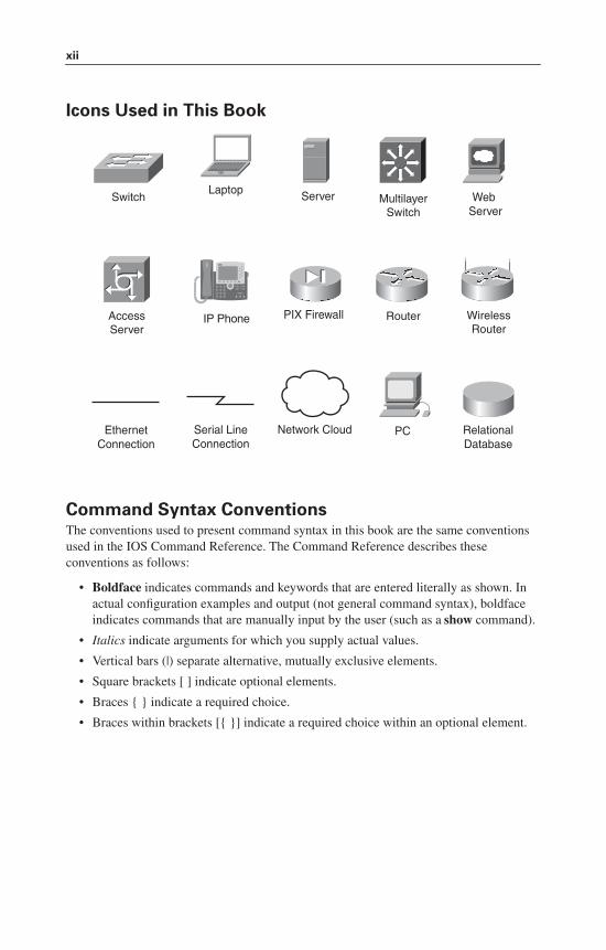
Icons Used in This Book
Command Syntax ConventionsThe conventions used to present command syntax in this book are the same conventions used in the IOS Command Reference. The Command Reference describes these conventions as follows:
• Boldface indicates commands and keywords that are entered literally as shown. In actual configuration examples and output (not general command syntax), boldface indicates commands that are manually input by the user (such as a show command).
• Italics indicate arguments for which you supply actual values.
• Vertical bars (|) separate alternative, mutually exclusive elements.
• Square brackets [ ] indicate optional elements.
• Braces { } indicate a required choice.
• Braces within brackets [{ }] indicate a required choice within an optional element.
Router
MultilayerSwitch
ServerSwitch
PCNetwork Cloud
Laptop
IP PhoneAccessServer
PIX Firewall
RelationalDatabase
WirelessRouter
WebServer
Serial LineConnection
EthernetConnection
xiii
IntroductionWelcome to BCMSN! In 2006, Cisco Press came to me and told me, albeit very quietly, that there was going to be a major revision of the CCNP certification exams. They then asked whether I would be interested in working on a command guide in the same fashion as my previous books for Cisco Press: the Cisco Networking Academy Program CCNA Command Quick Reference and the CCNA Portable Command Guide. The original idea was to create a single-volume command summary for all four of the new CCNP exams. However, early on in my research, I quickly discovered that there was far too much information in the four exams to create a single volume—that would have resulted in a book that was neither portable nor quick as a reference. So, I jokingly suggested that they let me author four books—one for each exam. Well, I guess you have to be careful what you wish for, because Cisco Press readily agreed. They were so excited about the idea that they offered to cut the proposed writing time by a few months to get these books to market faster. How nice of them, don’t you think?
This book is the second in a four-volume set that attempts to summarize the commands and concepts that you need to pass one of the CCNP certification exams—in this case, the Building Cisco Multilayer Switched Networks exam. It follows the format of my previous books, which are in fact a cleaned-up version of my own personal engineering journal. I have long been a fan of what I call the “Engineering Journal”—a small notebook that can be carried around and that contains little nuggets of information—commands that you forget, the IP addressing scheme of some remote part of the network, little reminders about how to do something you only have to do once or twice a year, but is vital to the integrity and maintenance of your network. This journal has been a constant companion by my side for the past eight years; I only teach some of these concepts every second or third year, so I constantly need to refresh commands and concepts, and learn new commands and ideas as they are released by Cisco. With the creation of two brand-new CCNP exams, the amount of new information out there is growing on an almost daily basis. There is always a new white paper to read, a new Webinar to view, another slideshow from a Networkers session that I didn’t get to. My journals are the best way for me to review because they are written in my own words, words that I can understand. At least, I better understand them, because if I didn’t, I have only myself to blame.
To make this guide a more realistic one for you to use, the folks at Cisco Press have decided to continue with my request for an appendix of blank pages—pages that are for you to put your own personal touches—your own configurations, commands that are not in this book but are needed in your world, and so on. That way this book will look less like my journal and more like your own.
I hope that you learn as much from reading this guide as I did when I wrote it.
xiv
Networking Devices Used in the Preparation of This BookTo verify the commands in this book, I had to try them out on a few different devices. The following is a list of the equipment I used in the writing of this book:
• C2620 router running Cisco IOS Software Release 12.3(7)T, with a fixed Fast Ethernet interface, a WIC-2A/S serial interface card, and a NM-1E Ethernet interface
• C2811 ISR bundle with PVDM2, CMME, a WIC-2T, FXS and FXO VICs, running 12.4(3g) IOS
• WS-C3560-24-EMI Catalyst switch, running 12.2(25)SE IOS
• WS-C3550-24-EMI Catalyst switch, running 12.1(9)EA1c IOS
• WS-C2960-24TT-L Catalyst switch, running 12.2(25)SE IOS
• WS-C2950-12 Catalyst switch, running Version C2950-C3.0(5.3)WC(1) Enterprise Edition software
• AIR-WLC4402 Wireless LAN Controller
These devices were not running the latest and greatest versions of Cisco IOS Software. Some of it is quite old.
Those of you familiar with Cisco devices will recognize that a majority of these commands work across the entire range of the Cisco product line. These commands are not limited to the platforms and Cisco IOS versions listed. In fact, in most cases, these devices are adequate for someone to continue his or her studies beyond the CCNP level, too.
Who Should Read This BookThis book is for those people preparing for the CCNP BCMSN exam, whether through self-study, on-the-job training and practice, study within the Cisco Academy Program, or study through the use of a Cisco Training Partner. There are also some handy hints and tips along the way to make life a bit easier for you in this endeavor. It is small enough that you will find it easy to carry around with you. Big, heavy textbooks might look impressive on your bookshelf in your office, but can you really carry them all around with you when you are working in some server room or equipment closet somewhere?
Organization of This BookThis book follows the list of objectives for the CCNP BCMSN exam:
• Chapter 1, “Network Design Requirements”—Provides an overview of the two different design models from Cisco—the Service-Oriented Network Architecture and the Enterprise Composite Network Model.
• Chapter 2, “VLANs”—Describes how to configure, verify, and troubleshoot VLANs, including topics such as Dynamic Trunking Protocol (DTP) and VLAN Trunking Protocol (VTP).
xv
• Chapter 3, “STP and EtherChanel”—Describes how to configure, verify, and troubleshoot Spanning Tree Protocol (STP), including topics such as configuring the root switch; port priorities; timers; PortFast; BPDU Guard; UplinkFast and BackboneFast; Configuring L2 and L3 EtherChannel; load balancing; and verifying EtherChannel.
• Chapter 4, “Inter-VLAN Routing”—Describes how to configure, verify, and troubleshoot inter-VLAN routing, including topics such as router-on-a-stick; switch virtual interfaces; Cisco Express Forwarding (CEF); and creating a routed port on a switch.
• Chapter 5, “High Availability”—Covers topics such as Hot Standby Router Protocol (HSRP), Virtual Router Redundancy Protocol (VRRP), and Gateway Load Balancing Protocol (GLBP).
• Chapter 6, “Wireless Client Access”—Describes how to configure and verify the configuration of a wireless LAN controller using both the Command-Line Wizard and the GUI Wizard.
• Chapter 7, “Minimizing Service Loss and Data Theft”—Covers topics such as port security, sticky MAC addresses, private VLANs, VLAN access maps, DHCP snooping, dynamic ARP inspection, 802.1x authentication, Cisco Discovery Protocol (CDP) issues, Secure Shell (SSH), vty access control lists (ACL), disabling unneeded services, and securing end device access ports.
• Chapter 8, “Voice Support in Campus Switches”—Covers topics such as attaching a Cisco IP Phone, configuring AutoQos on a 2960/3560 switch, configuring AutoQos on a 6500, and verifying AutoQoS information.
Did I Miss Anything?I am always interested to hear how my students, and now readers of my books, do on both vendor exams and future studies. If you would like to contact me and let me know how this book helped you in your certification goals, please do so. Did I miss anything? Let me know. I can’t guarantee I’ll answer your e-mail message, but I can guarantee that I will read all of them. My e-mail address is [email protected].

This page intentionally left blank
CHAPTER 1
Network DesignRequirements
This chapter provides information concerning the following topics:
• Cisco Service-Oriented Network Architecture
• Cisco Enterprise Composite Network Model
No commands are associated with this module of the CCNP BCMSN course objectives.
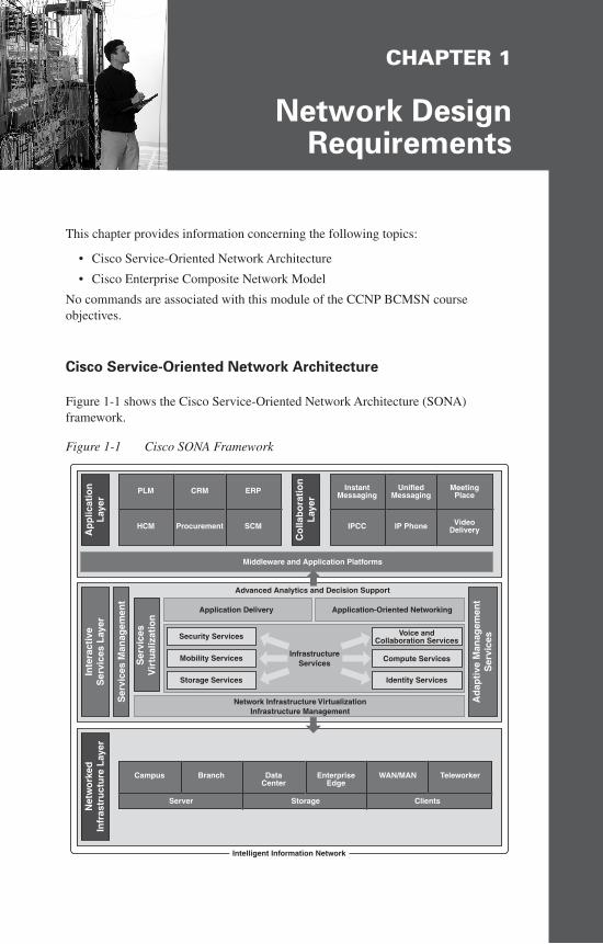
Cisco Service-Oriented Network Architecture
Figure 1-1 shows the Cisco Service-Oriented Network Architecture (SONA) framework.
Figure 1-1 Cisco SONA Framework
Net
wo
rked
Infr
astr
uct
ure
Lay
erIn
tera
ctiv
eS
ervi
ces
Lay
er
Ad
apti
ve M
anag
emen
tS
ervi
ces
Ser
vice
s M
anag
emen
t
Ser
vice
sV
irtu
aliz
atio
n
InfrastructureServices
Network Infrastructure VirtualizationInfrastructure Management
Middleware and Application Platforms
Intelligent Information Network
Advanced Analytics and Decision Support
Application Delivery Application-Oriented Networking
Voice andCollaboration Services
Compute Services
Identity Services
Security Services
Mobility Services
Storage Services
Campus Branch DataCenter
EnterpriseEdge
WAN/MAN Teleworker
Server Storage Clients
Ap
plic
atio
nL
ayer
Co
llab
ora
tio
nL
ayer
PLM CRM ERP
HCM Procurement SCM
InstantMessaging
UnifiedMessaging
MeetingPlace
IPCC IP Phone VideoDelivery
2 Cisco Enterprise Composite Network Model
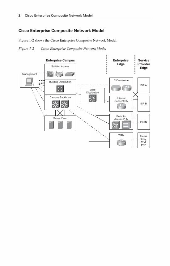
Cisco Enterprise Composite Network Model
Figure 1-2 shows the Cisco Enterprise Composite Network Model.
Figure 1-2 Cisco Enterprise Composite Network Model
Enterprise Campus EnterpriseEdge
ServiceProvider
Edge
ISP A
E-Commerce
ISP B
InternetConnectivity
EdgeDistribution
PSTN
Remote-Access VPN
FrameRelay, ATM,PPP
WAN
Management
Building Distribution
Campus Backbone
Server Farm
Building Access
CHAPTER 2
VLANs
This chapter provides information and commands concerning the following topics:
• Creating static VLANs
— Using VLAN-configuration mode
— Using VLAN Database mode
• Assigning ports to VLANs
• Using the range command
• Dynamic Trunking Protocol (DTP)
• Setting the encapsulation type
• Verifying VLAN information
• Saving VLAN configurations
• Erasing VLAN configurations
• Verifying VLAN trunking
• VLAN Trunking Protocol (VTP)
— Using VLAN Database mode
— Using global configuration mode
• Verifying VTP
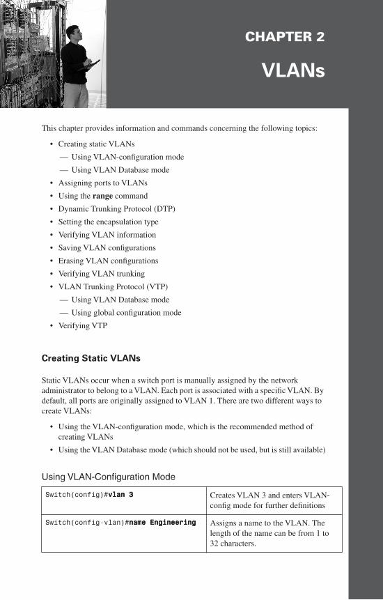
Creating Static VLANs
Static VLANs occur when a switch port is manually assigned by the network administrator to belong to a VLAN. Each port is associated with a specific VLAN. By default, all ports are originally assigned to VLAN 1. There are two different ways to create VLANs:
• Using the VLAN-configuration mode, which is the recommended method of creating VLANs
• Using the VLAN Database mode (which should not be used, but is still available)
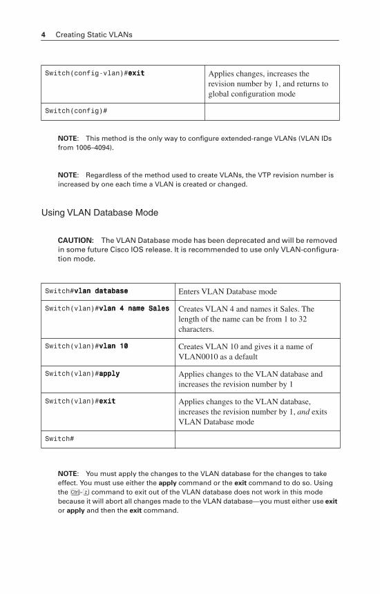
Using VLAN-Configuration Mode
Switch(config)#vvvvllllaaaannnn 3333 Creates VLAN 3 and enters VLAN-config mode for further definitions
Switch(config-vlan)#nnnnaaaammmmeeee EEEEnnnnggggiiiinnnneeeeeeeerrrriiiinnnngggg Assigns a name to the VLAN. The length of the name can be from 1 to 32 characters.
4 Creating Static VLANs
NOTE: This method is the only way to configure extended-range VLANs (VLAN IDs from 1006–4094).
NOTE: Regardless of the method used to create VLANs, the VTP revision number is increased by one each time a VLAN is created or changed.
Using VLAN Database Mode
CAUTION: The VLAN Database mode has been deprecated and will be removed in some future Cisco IOS release. It is recommended to use only VLAN-configura-tion mode.
NOTE: You must apply the changes to the VLAN database for the changes to take effect. You must use either the apply command or the exit command to do so. Using theÇ-z command to exit out of the VLAN database does not work in this mode because it will abort all changes made to the VLAN database—you must either use exit
or apply and then the exit command.
Switch(config-vlan)#eeeexxxxiiiitttt Applies changes, increases the revision number by 1, and returns to global configuration mode
Switch(config)#
Switch#vvvvllllaaaannnn ddddaaaattttaaaabbbbaaaasssseeee Enters VLAN Database mode
Switch(vlan)#vvvvllllaaaannnn 4444 nnnnaaaammmmeeee SSSSaaaalllleeeessss Creates VLAN 4 and names it Sales. The length of the name can be from 1 to 32 characters.
Switch(vlan)#vvvvllllaaaannnn 11110000 Creates VLAN 10 and gives it a name of VLAN0010 as a default
Switch(vlan)#aaaappppppppllllyyyy Applies changes to the VLAN database and increases the revision number by 1
Switch(vlan)#eeeexxxxiiiitttt Applies changes to the VLAN database, increases the revision number by 1, and exits VLAN Database mode
Switch#
Dynamic Trunking Protocol 5
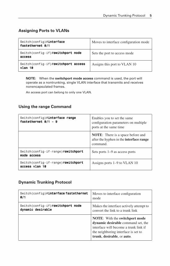
Assigning Ports to VLANs
NOTE: When the switchport mode access command is used, the port will operate as a nontrunking, single VLAN interface that transmits and receives nonencapsulated frames.
An access port can belong to only one VLAN.
Using the range Command
Dynamic Trunking Protocol
Switch(config)#iiiinnnntttteeeerrrrffffaaaacccceeee ffffaaaasssstttteeeetttthhhheeeerrrrnnnneeeetttt 0000////1111
Moves to interface configuration mode
Switch(config-if)#sssswwwwiiiittttcccchhhhppppoooorrrrtttt mmmmooooddddeeee aaaacccccccceeeessssssss
Sets the port to access mode
Switch(config-if)#sssswwwwiiiittttcccchhhhppppoooorrrrtttt aaaacccccccceeeessssssss vvvvllllaaaannnn 11110000
Assigns this port to VLAN 10
Switch(config)#iiiinnnntttteeeerrrrffffaaaacccceeee rrrraaaannnnggggeeee ffffaaaasssstttteeeetttthhhheeeerrrrnnnneeeetttt 0000////1111 –––– 9999
Enables you to set the same configuration parameters on multiple ports at the same time
NOTE: There is a space before and after the hyphen in the interface rangecommand.
Switch(config-if-range)#sssswwwwiiiittttcccchhhhppppoooorrrrtttt mmmmooooddddeeee aaaacccccccceeeessssssss
Sets ports 1–9 as access ports
Switch(config-if-range)#sssswwwwiiiittttcccchhhhppppoooorrrrtttt aaaacccccccceeeessssssss vvvvllllaaaannnn 11110000
Assigns ports 1–9 to VLAN 10
Switch(config)#iiiinnnntttteeeerrrrffffaaaacccceeee ffffaaaasssstttteeeetttthhhheeeerrrrnnnneeeetttt 0000////1111
Moves to interface configuration mode
Switch(config-if)#sssswwwwiiiittttcccchhhhppppoooorrrrtttt mmmmooooddddeeee ddddyyyynnnnaaaammmmiiiicccc ddddeeeessssiiiirrrraaaabbbblllleeee
Makes the interface actively attempt to convert the link to a trunk link
NOTE: With the switchport mode dynamic desirable command set, the interface will become a trunk link if the neighboring interface is set to trunk, desirable, or auto.
6 Setting the Encapsulation Type
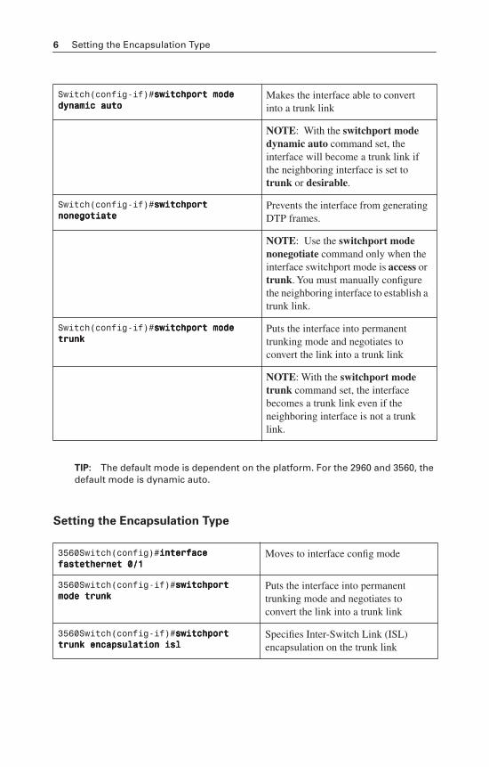
TIP: The default mode is dependent on the platform. For the 2960 and 3560, the default mode is dynamic auto.
Setting the Encapsulation Type
Switch(config-if)#sssswwwwiiiittttcccchhhhppppoooorrrrtttt mmmmooooddddeeee ddddyyyynnnnaaaammmmiiiicccc aaaauuuuttttoooo
Makes the interface able to convert into a trunk link
NOTE: With the switchport mode dynamic auto command set, the interface will become a trunk link if the neighboring interface is set to trunk or desirable.
Switch(config-if)#sssswwwwiiiittttcccchhhhppppoooorrrrtttt nnnnoooonnnneeeeggggoooottttiiiiaaaatttteeee
Prevents the interface from generating DTP frames.
NOTE: Use the switchport mode nonegotiate command only when the interface switchport mode is access ortrunk. You must manually configure the neighboring interface to establish a trunk link.
Switch(config-if)#sssswwwwiiiittttcccchhhhppppoooorrrrtttt mmmmooooddddeeee ttttrrrruuuunnnnkkkk
Puts the interface into permanent trunking mode and negotiates to convert the link into a trunk link
NOTE: With the switchport mode trunk command set, the interface becomes a trunk link even if the neighboring interface is not a trunk link.
3560Switch(config)#iiiinnnntttteeeerrrrffffaaaacccceeee ffffaaaasssstttteeeetttthhhheeeerrrrnnnneeeetttt 0000////1111
Moves to interface config mode
3560Switch(config-if)#sssswwwwiiiittttcccchhhhppppoooorrrrtttt mmmmooooddddeeee ttttrrrruuuunnnnkkkk
Puts the interface into permanent trunking mode and negotiates to convert the link into a trunk link
3560Switch(config-if)#sssswwwwiiiittttcccchhhhppppoooorrrrtttt ttttrrrruuuunnnnkkkk eeeennnnccccaaaappppssssuuuullllaaaattttiiiioooonnnn iiiissssllll
Specifies Inter-Switch Link (ISL) encapsulation on the trunk link
Saving VLAN Configurations 7
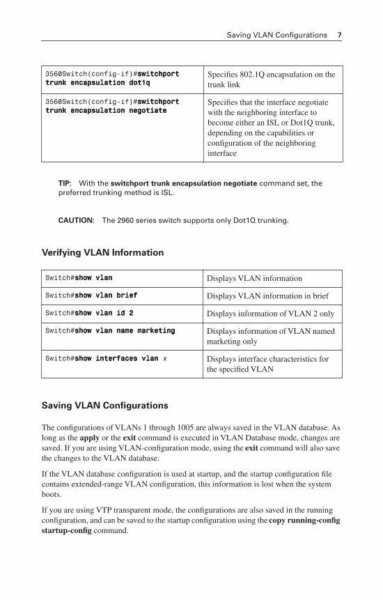
TIP: With the switchport trunk encapsulation negotiate command set, the preferred trunking method is ISL.
CAUTION: The 2960 series switch supports only Dot1Q trunking.
Verifying VLAN Information
Saving VLAN Configurations
The configurations of VLANs 1 through 1005 are always saved in the VLAN database. As long as the apply or the exit command is executed in VLAN Database mode, changes are saved. If you are using VLAN-configuration mode, using the exit command will also save the changes to the VLAN database.
If the VLAN database configuration is used at startup, and the startup configuration file contains extended-range VLAN configuration, this information is lost when the system boots.
If you are using VTP transparent mode, the configurations are also saved in the running configuration, and can be saved to the startup configuration using the copy running-config startup-config command.
3560Switch(config-if)#sssswwwwiiiittttcccchhhhppppoooorrrrtttt ttttrrrruuuunnnnkkkk eeeennnnccccaaaappppssssuuuullllaaaattttiiiioooonnnn ddddooootttt1111qqqq
Specifies 802.1Q encapsulation on the trunk link
3560Switch(config-if)#sssswwwwiiiittttcccchhhhppppoooorrrrtttt ttttrrrruuuunnnnkkkk eeeennnnccccaaaappppssssuuuullllaaaattttiiiioooonnnn nnnneeeeggggoooottttiiiiaaaatttteeee
Specifies that the interface negotiate with the neighboring interface to become either an ISL or Dot1Q trunk, depending on the capabilities or configuration of the neighboring interface
Switch#sssshhhhoooowwww vvvvllllaaaannnn Displays VLAN information
Switch#sssshhhhoooowwww vvvvllllaaaannnn bbbbrrrriiiieeeeffff Displays VLAN information in brief
Switch#sssshhhhoooowwww vvvvllllaaaannnn iiiidddd 2222 Displays information of VLAN 2 only
Switch#sssshhhhoooowwww vvvvllllaaaannnn nnnnaaaammmmeeee mmmmaaaarrrrkkkkeeeettttiiiinnnngggg Displays information of VLAN named marketing only
Switch#sssshhhhoooowwww iiiinnnntttteeeerrrrffffaaaacccceeeessss vvvvllllaaaannnn x Displays interface characteristics for the specified VLAN
8 Erasing VLAN Configurations
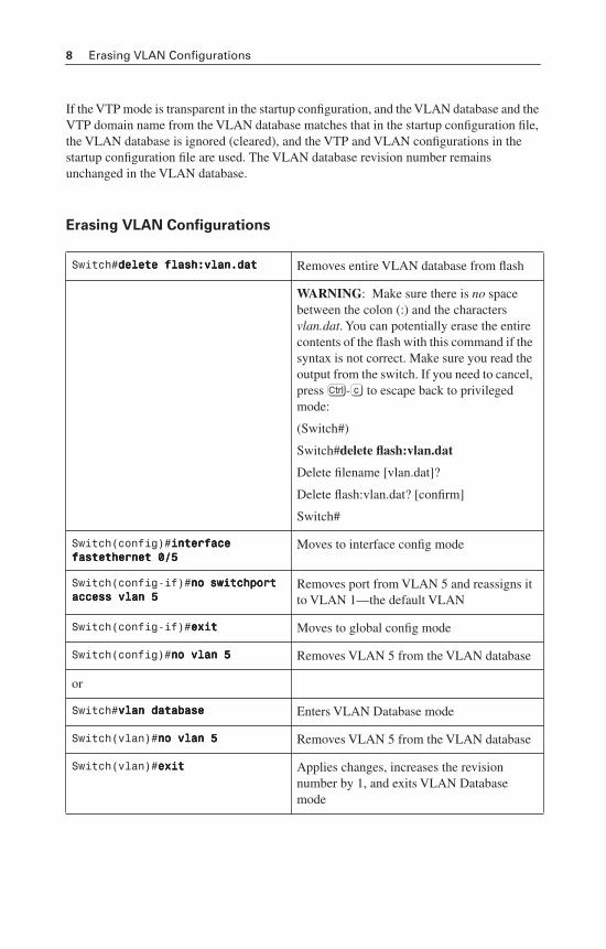
If the VTP mode is transparent in the startup configuration, and the VLAN database and the VTP domain name from the VLAN database matches that in the startup configuration file, the VLAN database is ignored (cleared), and the VTP and VLAN configurations in the startup configuration file are used. The VLAN database revision number remains unchanged in the VLAN database.
Erasing VLAN Configurations
Switch#ddddeeeelllleeeetttteeee ffffllllaaaasssshhhh::::vvvvllllaaaannnn....ddddaaaatttt Removes entire VLAN database from flash
WARNING: Make sure there is no space between the colon (:) and the characters vlan.dat. You can potentially erase the entire contents of the flash with this command if the syntax is not correct. Make sure you read the output from the switch. If you need to cancel, pressÇ-c to escape back to privileged mode:
(Switch#)
Switch#delete flash:vlan.dat
Delete filename [vlan.dat]?
Delete flash:vlan.dat? [confirm]
Switch#
Switch(config)#iiiinnnntttteeeerrrrffffaaaacccceeee ffffaaaasssstttteeeetttthhhheeeerrrrnnnneeeetttt 0000////5555
Moves to interface config mode
Switch(config-if)#nnnnoooo sssswwwwiiiittttcccchhhhppppoooorrrrtttt aaaacccccccceeeessssssss vvvvllllaaaannnn 5555
Removes port from VLAN 5 and reassigns it to VLAN 1—the default VLAN
Switch(config-if)#eeeexxxxiiiitttt Moves to global config mode
Switch(config)#nnnnoooo vvvvllllaaaannnn 5555 Removes VLAN 5 from the VLAN database
or
Switch#vvvvllllaaaannnn ddddaaaattttaaaabbbbaaaasssseeee Enters VLAN Database mode
Switch(vlan)#nnnnoooo vvvvllllaaaannnn 5555 Removes VLAN 5 from the VLAN database
Switch(vlan)#eeeexxxxiiiitttt Applies changes, increases the revision number by 1, and exits VLAN Database mode
VLAN Trunking Protocol 9
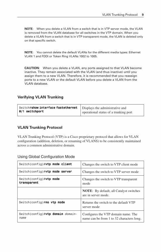
NOTE: When you delete a VLAN from a switch that is in VTP server mode, the VLAN is removed from the VLAN database for all switches in the VTP domain. When you delete a VLAN from a switch that is in VTP transparent mode, the VLAN is deleted only on that specific switch.
NOTE: You cannot delete the default VLANs for the different media types: Ethernet VLAN 1 and FDDI or Token Ring VLANs 1002 to 1005.
CAUTION: When you delete a VLAN, any ports assigned to that VLAN become inactive. They remain associated with the VLAN (and thus inactive) until you assign them to a new VLAN. Therefore, it is recommended that you reassign ports to a new VLAN or the default VLAN before you delete a VLAN from the VLAN database.
Verifying VLAN Trunking
VLAN Trunking Protocol
VLAN Trunking Protocol (VTP) is a Cisco proprietary protocol that allows for VLAN configuration (addition, deletion, or renaming of VLANS) to be consistently maintained across a common administrative domain.
Using Global Configuration Mode
Switch#sssshhhhoooowwww iiiinnnntttteeeerrrrffffaaaacccceeee ffffaaaasssstttteeeetttthhhheeeerrrrnnnneeeetttt 0000////1111 sssswwwwiiiittttcccchhhhppppoooorrrrtttt
Displays the administrative and operational status of a trunking port
Switch(config)#vvvvttttpppp mmmmooooddddeeee cccclllliiiieeeennnntttt Changes the switch to VTP client mode
Switch(config)#vvvvttttpppp mmmmooooddddeeee sssseeeerrrrvvvveeeerrrr Changes the switch to VTP server mode
Switch(config)#vvvvttttpppp mmmmooooddddeeee ttttrrrraaaannnnssssppppaaaarrrreeeennnntttt
Changes the switch to VTP transparent mode
NOTE: By default, all Catalyst switches are in server mode.
Switch(config)#nnnnoooo vvvvttttpppp mmmmooooddddeeee Returns the switch to the default VTP server mode
Switch(config)#vvvvttttpppp ddddoooommmmaaaaiiiinnnn domain-name
Configures the VTP domain name. The name can be from 1 to 32 characters long.
10 VLAN Trunking Protocol
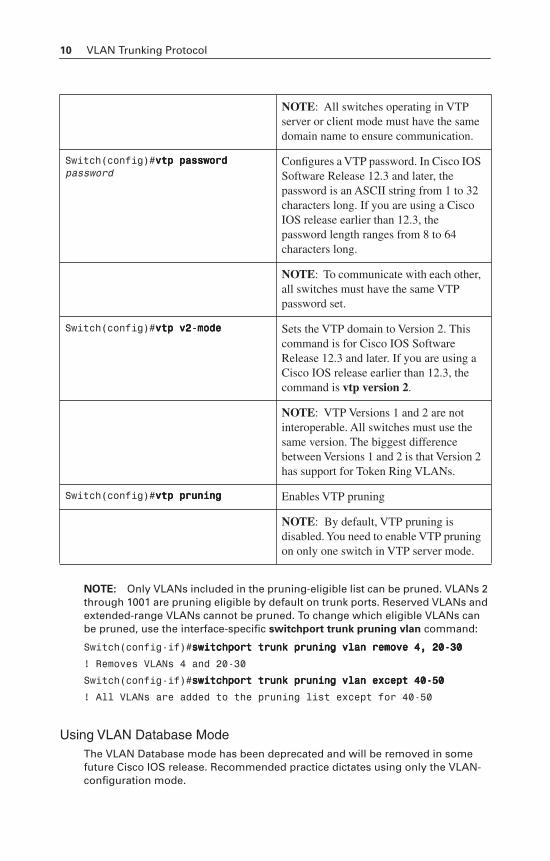
NOTE: Only VLANs included in the pruning-eligible list can be pruned. VLANs 2 through 1001 are pruning eligible by default on trunk ports. Reserved VLANs and extended-range VLANs cannot be pruned. To change which eligible VLANs can be pruned, use the interface-specific switchport trunk pruning vlan command:
Switch(config-if)#sssswwwwiiiittttcccchhhhppppoooorrrrtttt ttttrrrruuuunnnnkkkk pppprrrruuuunnnniiiinnnngggg vvvvllllaaaannnn rrrreeeemmmmoooovvvveeee 4444,,,, 22220000----33330000
! Removes VLANs 4 and 20-30
Switch(config-if)#sssswwwwiiiittttcccchhhhppppoooorrrrtttt ttttrrrruuuunnnnkkkk pppprrrruuuunnnniiiinnnngggg vvvvllllaaaannnn eeeexxxxcccceeeepppptttt 44440000----55550000
! All VLANs are added to the pruning list except for 40-50
Using VLAN Database ModeThe VLAN Database mode has been deprecated and will be removed in some future Cisco IOS release. Recommended practice dictates using only the VLAN-configuration mode.
NOTE: All switches operating in VTP server or client mode must have the same domain name to ensure communication.
Switch(config)#vvvvttttpppp ppppaaaasssssssswwwwoooorrrrdddd password
Configures a VTP password. In Cisco IOS Software Release 12.3 and later, the password is an ASCII string from 1 to 32 characters long. If you are using a Cisco IOS release earlier than 12.3, the password length ranges from 8 to 64 characters long.
NOTE: To communicate with each other, all switches must have the same VTP password set.
Switch(config)#vvvvttttpppp vvvv2222----mmmmooooddddeeee Sets the VTP domain to Version 2. This command is for Cisco IOS Software Release 12.3 and later. If you are using a Cisco IOS release earlier than 12.3, the command is vtp version 2.
NOTE: VTP Versions 1 and 2 are not interoperable. All switches must use the same version. The biggest difference between Versions 1 and 2 is that Version 2 has support for Token Ring VLANs.
Switch(config)#vvvvttttpppp pppprrrruuuunnnniiiinnnngggg Enables VTP pruning
NOTE: By default, VTP pruning is disabled. You need to enable VTP pruning on only one switch in VTP server mode.
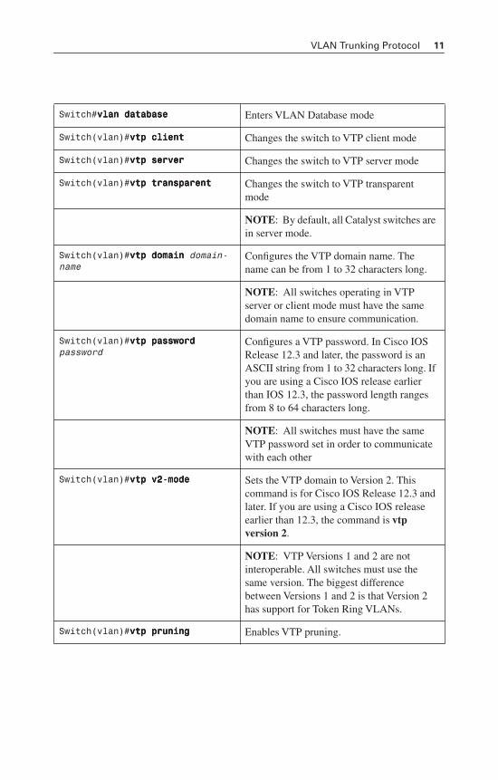
VLAN Trunking Protocol 11
Switch#vvvvllllaaaannnn ddddaaaattttaaaabbbbaaaasssseeee Enters VLAN Database mode
Switch(vlan)#vvvvttttpppp cccclllliiiieeeennnntttt Changes the switch to VTP client mode
Switch(vlan)#vvvvttttpppp sssseeeerrrrvvvveeeerrrr Changes the switch to VTP server mode
Switch(vlan)#vvvvttttpppp ttttrrrraaaannnnssssppppaaaarrrreeeennnntttt Changes the switch to VTP transparent mode
NOTE: By default, all Catalyst switches are in server mode.
Switch(vlan)#vvvvttttpppp ddddoooommmmaaaaiiiinnnn domain-name
Configures the VTP domain name. The name can be from 1 to 32 characters long.
NOTE: All switches operating in VTP server or client mode must have the same domain name to ensure communication.
Switch(vlan)#vvvvttttpppp ppppaaaasssssssswwwwoooorrrrdddd password
Configures a VTP password. In Cisco IOS Release 12.3 and later, the password is an ASCII string from 1 to 32 characters long. If you are using a Cisco IOS release earlier than IOS 12.3, the password length ranges from 8 to 64 characters long.
NOTE: All switches must have the same VTP password set in order to communicate with each other
Switch(vlan)#vvvvttttpppp vvvv2222----mmmmooooddddeeee Sets the VTP domain to Version 2. This command is for Cisco IOS Release 12.3 and later. If you are using a Cisco IOS release earlier than 12.3, the command is vtpversion 2.
NOTE: VTP Versions 1 and 2 are not interoperable. All switches must use the same version. The biggest difference between Versions 1 and 2 is that Version 2 has support for Token Ring VLANs.
Switch(vlan)#vvvvttttpppp pppprrrruuuunnnniiiinnnngggg Enables VTP pruning.
12 Verifying VTP
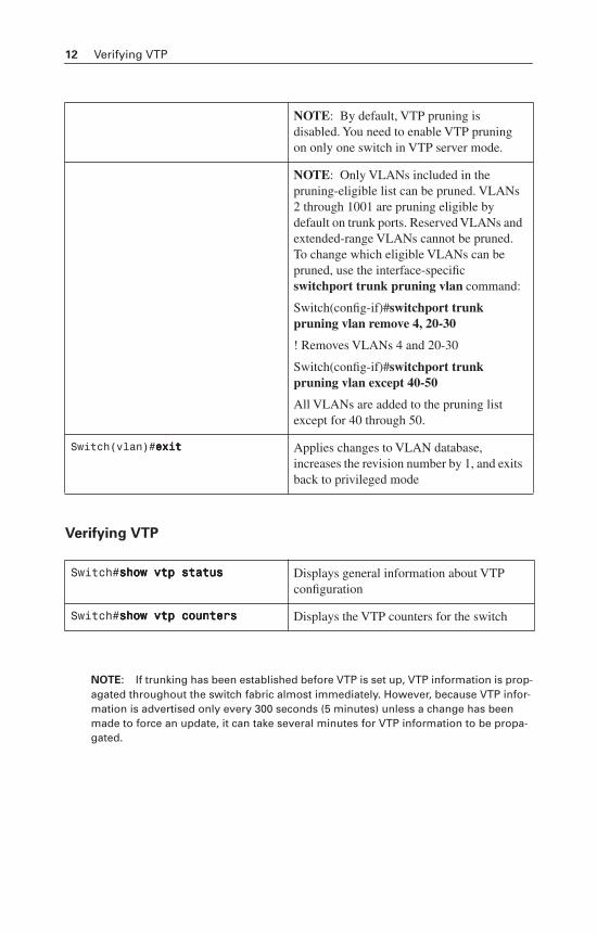
Verifying VTP
NOTE: If trunking has been established before VTP is set up, VTP information is prop-agated throughout the switch fabric almost immediately. However, because VTP infor-mation is advertised only every 300 seconds (5 minutes) unless a change has been made to force an update, it can take several minutes for VTP information to be propa-gated.
NOTE: By default, VTP pruning is disabled. You need to enable VTP pruning on only one switch in VTP server mode.
NOTE: Only VLANs included in the pruning-eligible list can be pruned. VLANs 2 through 1001 are pruning eligible by default on trunk ports. Reserved VLANs and extended-range VLANs cannot be pruned. To change which eligible VLANs can be pruned, use the interface-specific switchport trunk pruning vlan command:
Switch(config-if)#switchport trunk pruning vlan remove 4, 20-30
! Removes VLANs 4 and 20-30
Switch(config-if)#switchport trunk pruning vlan except 40-50
All VLANs are added to the pruning list except for 40 through 50.
Switch(vlan)#eeeexxxxiiiitttt Applies changes to VLAN database, increases the revision number by 1, and exits back to privileged mode
Switch#sssshhhhoooowwww vvvvttttpppp ssssttttaaaattttuuuussss Displays general information about VTP configuration
Switch#sssshhhhoooowwww vvvvttttpppp ccccoooouuuunnnntttteeeerrrrssss Displays the VTP counters for the switch
Configuration Example: VLANs 13
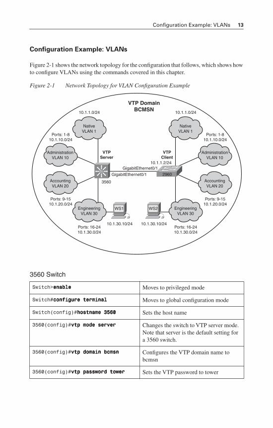
Configuration Example: VLANs
Figure 2-1 shows the network topology for the configuration that follows, which shows how to configure VLANs using the commands covered in this chapter.
Figure 2-1 Network Topology for VLAN Configuration Example
3560 Switch
Switch>eeeennnnaaaabbbblllleeee Moves to privileged mode
Switch#ccccoooonnnnffffiiiigggguuuurrrreeee tttteeeerrrrmmmmiiiinnnnaaaallll Moves to global configuration mode
Switch(config)#hhhhoooossssttttnnnnaaaammmmeeee 3333555566660000 Sets the host name
3560(config)#vvvvttttpppp mmmmooooddddeeee sssseeeerrrrvvvveeeerrrr Changes the switch to VTP server mode. Note that server is the default setting for a 3560 switch.
3560(config)#vvvvttttpppp ddddoooommmmaaaaiiiinnnn bbbbccccmmmmssssnnnn Configures the VTP domain name to bcmsn
3560(config)#vvvvttttpppp ppppaaaasssssssswwwwoooorrrrdddd ttttoooowwwweeeerrrr Sets the VTP password to tower
VTP DomainBCMSN
2960
EngineeringVLAN 30
NativeVLAN 1
AdministrationVLAN 10
AccountingVLAN 20
10.1.30.10/24
10.1.1.2/24
Ports: 16-2410.1.30.0/24
GigabitEthernet0/1
GigabitEthernet0/1
Ports: 9-1510.1.20.0/24
Ports: 1-810.1.10.0/24
10.1.1.0/24
EngineeringVLAN 30
NativeVLAN 1
AdministrationVLAN 10
AccountingVLAN 20
Ports: 16-2410.1.30.0/24
Ports: 9-1510.1.20.0/24
Ports: 1-810.1.10.0/24
10.1.1.0/24
WS1
10.1.30.10/24
WS2
VTPServer
3560
VTPClient
Si
14 Configuration Example: VLANs
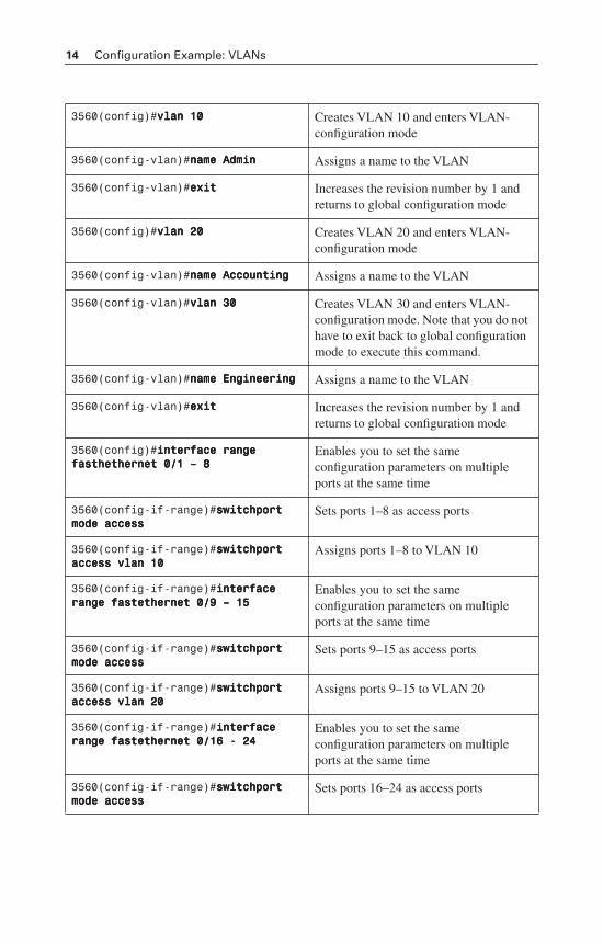
3560(config)#vvvvllllaaaannnn 11110000 Creates VLAN 10 and enters VLAN-configuration mode
3560(config-vlan)#nnnnaaaammmmeeee AAAAddddmmmmiiiinnnn Assigns a name to the VLAN
3560(config-vlan)#eeeexxxxiiiitttt Increases the revision number by 1 and returns to global configuration mode
3560(config)#vvvvllllaaaannnn 22220000 Creates VLAN 20 and enters VLAN-configuration mode
3560(config-vlan)#nnnnaaaammmmeeee AAAAccccccccoooouuuunnnnttttiiiinnnngggg Assigns a name to the VLAN
3560(config-vlan)#vvvvllllaaaannnn 33330000 Creates VLAN 30 and enters VLAN-configuration mode. Note that you do not have to exit back to global configuration mode to execute this command.
3560(config-vlan)#nnnnaaaammmmeeee EEEEnnnnggggiiiinnnneeeeeeeerrrriiiinnnngggg Assigns a name to the VLAN
3560(config-vlan)#eeeexxxxiiiitttt Increases the revision number by 1 and returns to global configuration mode
3560(config)#iiiinnnntttteeeerrrrffffaaaacccceeee rrrraaaannnnggggeeee ffffaaaasssstttthhhheeeetttthhhheeeerrrrnnnneeeetttt 0000////1111 –––– 8888
Enables you to set the same configuration parameters on multiple ports at the same time
3560(config-if-range)#sssswwwwiiiittttcccchhhhppppoooorrrrtttt mmmmooooddddeeee aaaacccccccceeeessssssss
Sets ports 1–8 as access ports
3560(config-if-range)#sssswwwwiiiittttcccchhhhppppoooorrrrtttt aaaacccccccceeeessssssss vvvvllllaaaannnn 11110000
Assigns ports 1–8 to VLAN 10
3560(config-if-range)#iiiinnnntttteeeerrrrffffaaaacccceeee rrrraaaannnnggggeeee ffffaaaasssstttteeeetttthhhheeeerrrrnnnneeeetttt 0000////9999 –––– 11115555
Enables you to set the same configuration parameters on multiple ports at the same time
3560(config-if-range)#sssswwwwiiiittttcccchhhhppppoooorrrrtttt mmmmooooddddeeee aaaacccccccceeeessssssss
Sets ports 9–15 as access ports
3560(config-if-range)#sssswwwwiiiittttcccchhhhppppoooorrrrtttt aaaacccccccceeeessssssss vvvvllllaaaannnn 22220000
Assigns ports 9–15 to VLAN 20
3560(config-if-range)#iiiinnnntttteeeerrrrffffaaaacccceeee rrrraaaannnnggggeeee ffffaaaasssstttteeeetttthhhheeeerrrrnnnneeeetttt 0000////11116666 ---- 22224444
Enables you to set the same configuration parameters on multiple ports at the same time
3560(config-if-range)#sssswwwwiiiittttcccchhhhppppoooorrrrtttt mmmmooooddddeeee aaaacccccccceeeessssssss
Sets ports 16–24 as access ports
Configuration Example: VLANs 15
2960 Switch
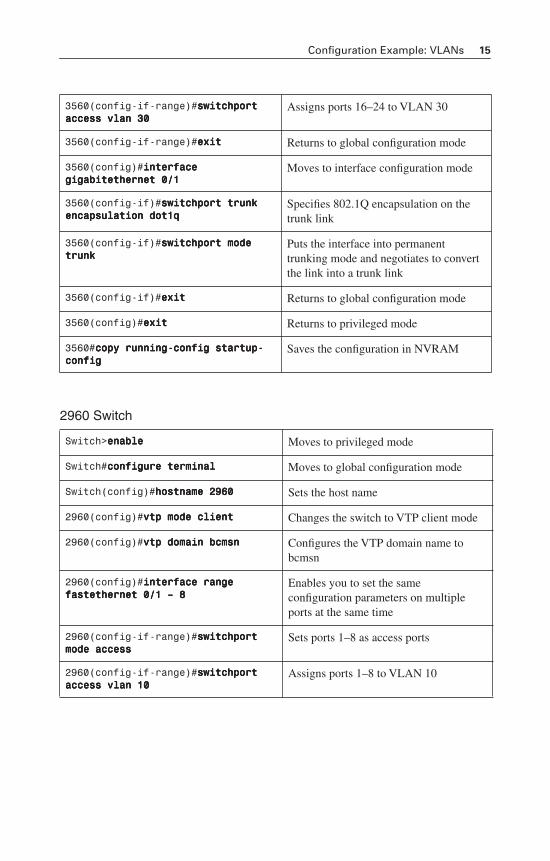
3560(config-if-range)#sssswwwwiiiittttcccchhhhppppoooorrrrtttt aaaacccccccceeeessssssss vvvvllllaaaannnn 33330000
Assigns ports 16–24 to VLAN 30
3560(config-if-range)#eeeexxxxiiiitttt Returns to global configuration mode
3560(config)#iiiinnnntttteeeerrrrffffaaaacccceeee ggggiiiiggggaaaabbbbiiiitttteeeetttthhhheeeerrrrnnnneeeetttt 0000////1111
Moves to interface configuration mode
3560(config-if)#sssswwwwiiiittttcccchhhhppppoooorrrrtttt ttttrrrruuuunnnnkkkk eeeennnnccccaaaappppssssuuuullllaaaattttiiiioooonnnn ddddooootttt1111qqqq
Specifies 802.1Q encapsulation on the trunk link
3560(config-if)#sssswwwwiiiittttcccchhhhppppoooorrrrtttt mmmmooooddddeeee ttttrrrruuuunnnnkkkk
Puts the interface into permanent trunking mode and negotiates to convert the link into a trunk link
3560(config-if)#eeeexxxxiiiitttt Returns to global configuration mode
3560(config)#eeeexxxxiiiitttt Returns to privileged mode
3560#ccccooooppppyyyy rrrruuuunnnnnnnniiiinnnngggg----ccccoooonnnnffffiiiigggg ssssttttaaaarrrrttttuuuupppp----ccccoooonnnnffffiiiigggg
Saves the configuration in NVRAM
Switch>eeeennnnaaaabbbblllleeee Moves to privileged mode
Switch#ccccoooonnnnffffiiiigggguuuurrrreeee tttteeeerrrrmmmmiiiinnnnaaaallll Moves to global configuration mode
Switch(config)#hhhhoooossssttttnnnnaaaammmmeeee 2222999966660000 Sets the host name
2960(config)#vvvvttttpppp mmmmooooddddeeee cccclllliiiieeeennnntttt Changes the switch to VTP client mode
2960(config)#vvvvttttpppp ddddoooommmmaaaaiiiinnnn bbbbccccmmmmssssnnnn Configures the VTP domain name to bcmsn
2960(config)#iiiinnnntttteeeerrrrffffaaaacccceeee rrrraaaannnnggggeeee ffffaaaasssstttteeeetttthhhheeeerrrrnnnneeeetttt 0000////1111 –––– 8888
Enables you to set the same configuration parameters on multiple ports at the same time
2960(config-if-range)#sssswwwwiiiittttcccchhhhppppoooorrrrtttt mmmmooooddddeeee aaaacccccccceeeessssssss
Sets ports 1–8 as access ports
2960(config-if-range)#sssswwwwiiiittttcccchhhhppppoooorrrrtttt aaaacccccccceeeessssssss vvvvllllaaaannnn 11110000
Assigns ports 1–8 to VLAN 10
16 Configuration Example: VLANs
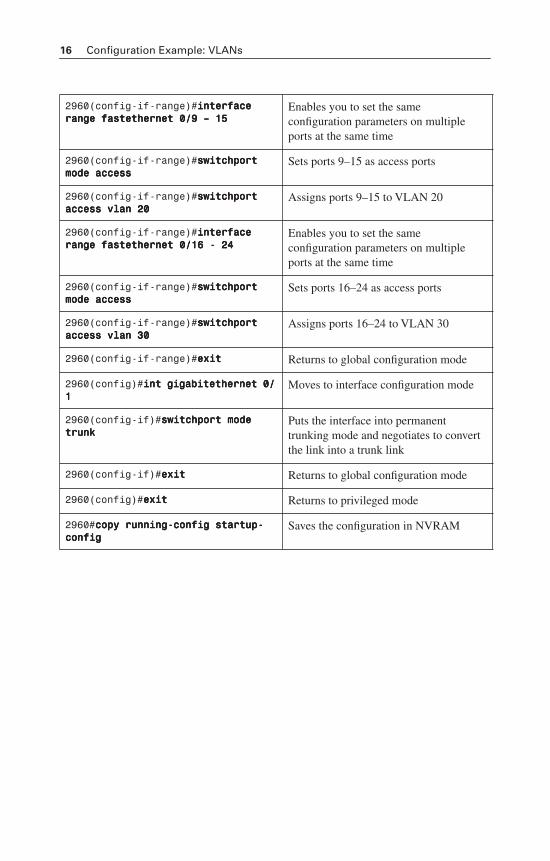
2960(config-if-range)#iiiinnnntttteeeerrrrffffaaaacccceeee rrrraaaannnnggggeeee ffffaaaasssstttteeeetttthhhheeeerrrrnnnneeeetttt 0000////9999 –––– 11115555
Enables you to set the same configuration parameters on multiple ports at the same time
2960(config-if-range)#sssswwwwiiiittttcccchhhhppppoooorrrrtttt mmmmooooddddeeee aaaacccccccceeeessssssss
Sets ports 9–15 as access ports
2960(config-if-range)#sssswwwwiiiittttcccchhhhppppoooorrrrtttt aaaacccccccceeeessssssss vvvvllllaaaannnn 22220000
Assigns ports 9–15 to VLAN 20
2960(config-if-range)#iiiinnnntttteeeerrrrffffaaaacccceeee rrrraaaannnnggggeeee ffffaaaasssstttteeeetttthhhheeeerrrrnnnneeeetttt 0000////11116666 ---- 22224444
Enables you to set the same configuration parameters on multiple ports at the same time
2960(config-if-range)#sssswwwwiiiittttcccchhhhppppoooorrrrtttt mmmmooooddddeeee aaaacccccccceeeessssssss
Sets ports 16–24 as access ports
2960(config-if-range)#sssswwwwiiiittttcccchhhhppppoooorrrrtttt aaaacccccccceeeessssssss vvvvllllaaaannnn 33330000
Assigns ports 16–24 to VLAN 30
2960(config-if-range)#eeeexxxxiiiitttt Returns to global configuration mode
2960(config)#iiiinnnntttt ggggiiiiggggaaaabbbbiiiitttteeeetttthhhheeeerrrrnnnneeeetttt 0000////1111
Moves to interface configuration mode
2960(config-if)#sssswwwwiiiittttcccchhhhppppoooorrrrtttt mmmmooooddddeeee ttttrrrruuuunnnnkkkk
Puts the interface into permanent trunking mode and negotiates to convert the link into a trunk link
2960(config-if)#eeeexxxxiiiitttt Returns to global configuration mode
2960(config)#eeeexxxxiiiitttt Returns to privileged mode
2960#ccccooooppppyyyy rrrruuuunnnnnnnniiiinnnngggg----ccccoooonnnnffffiiiigggg ssssttttaaaarrrrttttuuuupppp----ccccoooonnnnffffiiiigggg
Saves the configuration in NVRAM
CHAPTER 3
STP and EtherChannel
This chapter provides information and commands concerning the following topics:
Spanning Tree Protocol
• Enabling Spanning Tree Protocol (STP)
• Configuring the root switch
• Configuring a secondary root switch
• Configuring port priority
• Configuring the path cost
• Configuring the switch priority of a VLAN
• Configuring STP timers
• Verifying STP
• Optional STP configurations
— PortFast
— BPDU Guard
— BPDU Filtering
— UplinkFast
— BackboneFast
— Root Guard
— Loop Guard
— Unidirectional Link Detection (UDLD)
• Changing the spanning-tree mode
• Extended System ID
• Enabling Rapid Spanning Tree
• Enabling Multiple Spanning Tree
• Verifying MST
• Troubleshooting STP
EtherChannel
• Interface modes in EtherChannel
— Without Port aggregation protocol (PAgP) or Link Aggregation Control Protocol (LACP)
— With PagP
— With LACP
• Guidelines for configuring EtherChannel
• Configuring L2 EtherChannel
18 Spanning Tree Protocol
• Configuring L3 EtherChannel
• Verifying EtherChannel
• Configuring EtherChannel load balancing
• Types of EtherChannel load balancing
• Verifying EtherChannel load balancing
Spanning Tree Protocol
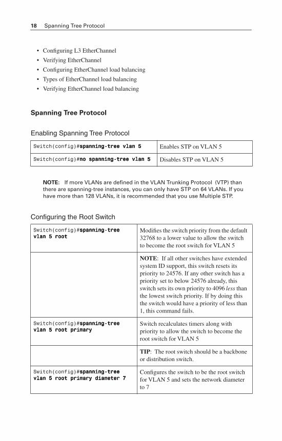
Enabling Spanning Tree Protocol
NOTE: If more VLANs are defined in the VLAN Trunking Protocol (VTP) than there are spanning-tree instances, you can only have STP on 64 VLANs. If you have more than 128 VLANs, it is recommended that you use Multiple STP.
Configuring the Root Switch
Switch(config)#ssssppppaaaannnnnnnniiiinnnngggg----ttttrrrreeeeeeee vvvvllllaaaannnn 5555 Enables STP on VLAN 5
Switch(config)#nnnnoooo ssssppppaaaannnnnnnniiiinnnngggg----ttttrrrreeeeeeee vvvvllllaaaannnn 5555 Disables STP on VLAN 5
Switch(config)#ssssppppaaaannnnnnnniiiinnnngggg----ttttrrrreeeeeeee vvvvllllaaaannnn 5555 rrrrooooooootttt
Modifies the switch priority from the default 32768 to a lower value to allow the switch to become the root switch for VLAN 5
NOTE: If all other switches have extended system ID support, this switch resets its priority to 24576. If any other switch has a priority set to below 24576 already, this switch sets its own priority to 4096 less thanthe lowest switch priority. If by doing this the switch would have a priority of less than 1, this command fails.
Switch(config)#ssssppppaaaannnnnnnniiiinnnngggg----ttttrrrreeeeeeee vvvvllllaaaannnn 5555 rrrrooooooootttt pppprrrriiiimmmmaaaarrrryyyy
Switch recalculates timers along with priority to allow the switch to become the root switch for VLAN 5
TIP: The root switch should be a backbone or distribution switch.
Switch(config)#ssssppppaaaannnnnnnniiiinnnngggg----ttttrrrreeeeeeee vvvvllllaaaannnn 5555 rrrrooooooootttt pppprrrriiiimmmmaaaarrrryyyy ddddiiiiaaaammmmeeeetttteeeerrrr 7777
Configures the switch to be the root switch for VLAN 5 and sets the network diameter to 7
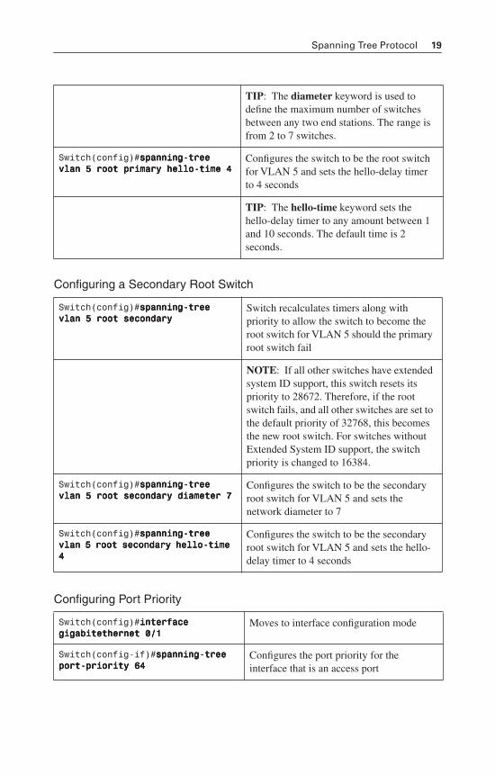
Spanning Tree Protocol 19
Configuring a Secondary Root Switch
Configuring Port Priority
TIP: The diameter keyword is used to define the maximum number of switches between any two end stations. The range is from 2 to 7 switches.
Switch(config)#ssssppppaaaannnnnnnniiiinnnngggg----ttttrrrreeeeeeee vvvvllllaaaannnn 5555 rrrrooooooootttt pppprrrriiiimmmmaaaarrrryyyy hhhheeeelllllllloooo----ttttiiiimmmmeeee 4444
Configures the switch to be the root switch for VLAN 5 and sets the hello-delay timer to 4 seconds
TIP: The hello-time keyword sets the hello-delay timer to any amount between 1 and 10 seconds. The default time is 2 seconds.
Switch(config)#ssssppppaaaannnnnnnniiiinnnngggg----ttttrrrreeeeeeee vvvvllllaaaannnn 5555 rrrrooooooootttt sssseeeeccccoooonnnnddddaaaarrrryyyy
Switch recalculates timers along with priority to allow the switch to become the root switch for VLAN 5 should the primary root switch fail
NOTE: If all other switches have extended system ID support, this switch resets its priority to 28672. Therefore, if the root switch fails, and all other switches are set to the default priority of 32768, this becomes the new root switch. For switches without Extended System ID support, the switch priority is changed to 16384.
Switch(config)#ssssppppaaaannnnnnnniiiinnnngggg----ttttrrrreeeeeeee vvvvllllaaaannnn 5555 rrrrooooooootttt sssseeeeccccoooonnnnddddaaaarrrryyyy ddddiiiiaaaammmmeeeetttteeeerrrr 7777
Configures the switch to be the secondary root switch for VLAN 5 and sets the network diameter to 7
Switch(config)#ssssppppaaaannnnnnnniiiinnnngggg----ttttrrrreeeeeeee vvvvllllaaaannnn 5555 rrrrooooooootttt sssseeeeccccoooonnnnddddaaaarrrryyyy hhhheeeelllllllloooo----ttttiiiimmmmeeee 4444
Configures the switch to be the secondary root switch for VLAN 5 and sets the hello-delay timer to 4 seconds
Switch(config)#iiiinnnntttteeeerrrrffffaaaacccceeee ggggiiiiggggaaaabbbbiiiitttteeeetttthhhheeeerrrrnnnneeeetttt 0000////1111
Moves to interface configuration mode
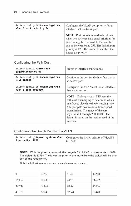
Switch(config-if)#ssssppppaaaannnnnnnniiiinnnngggg----ttttrrrreeeeeeee ppppoooorrrrtttt----pppprrrriiiioooorrrriiiittttyyyy 66664444
Configures the port priority for the interface that is an access port
20 Spanning Tree Protocol
Configuring the Path Cost
Configuring the Switch Priority of a VLAN
NOTE: With the priority keyword, the range is 0 to 61440 in increments of 4096. The default is 32768. The lower the priority, the more likely the switch will be cho-sen as the root switch.
Only the following numbers can be used as a priority value:
Switch(config-if)#ssssppppaaaannnnnnnniiiinnnngggg----ttttrrrreeeeeeee vvvvllllaaaannnn 5555 ppppoooorrrrtttt----pppprrrriiiioooorrrriiiittttyyyy 66664444
Configures the VLAN port priority for an interface that is a trunk port
NOTE: Port priority is used to break a tie when two switches have equal priorities for determining the root switch. The number can be between 0 and 255. The default port priority is 128. The lower the number, the higher the priority.
Switch(config)#iiiinnnntttteeeerrrrffffaaaacccceeee ggggiiiiggggaaaabbbbiiiitttteeeetttthhhheeeerrrrnnnneeeetttt 0000////1111
Moves to interface config mode
Switch(config-if)#ssssppppaaaannnnnnnniiiinnnngggg----ttttrrrreeeeeeee ccccoooosssstttt 111100000000000000000000
Configures the cost for the interface that is an access port
Switch(config-if)#ssssppppaaaannnnnnnniiiinnnngggg----ttttrrrreeeeeeee vvvvllllaaaannnn 5555 ccccoooosssstttt 1111000000000000000000000000
Configures the VLAN cost for an interface that is a trunk port
NOTE: If a loop occurs, STP uses the path cost when trying to determine which interface to place into the forwarding state. A higher path cost means a lower speed transmission. The range of the costkeyword is 1 through 200000000. The default is based on the media speed of the interface.
Switch(config)#ssssppppaaaannnnnnnniiiinnnngggg----ttttrrrreeeeeeee vvvvllllaaaannnn 5555 pppprrrriiiioooorrrriiiittttyyyy 11112222222288888888
Configures the switch priority of VLAN 5 to 12288
0 4096 8192 12288
16384 20480 24576 28672
32768 36864 40960 45056
49152 53248 57344 61440
Spanning Tree Protocol 21
CAUTION: Cisco recommends caution when using this command. Cisco further recommends that the spanning-tree vlan x root primary or the spanning-tree
vlan x root secondary command be used instead to modify the switch priority.
Configuring STP Timers
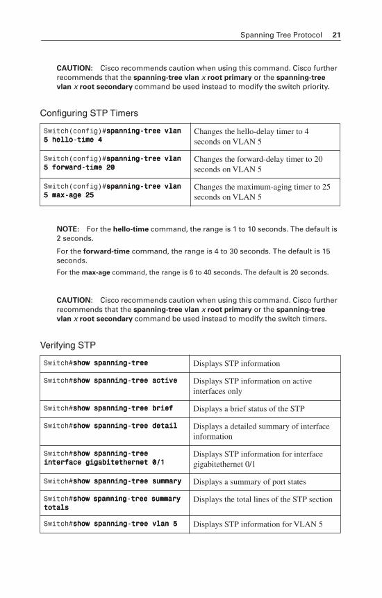
NOTE: For the hello-time command, the range is 1 to 10 seconds. The default is 2 seconds.
For the forward-time command, the range is 4 to 30 seconds. The default is 15 seconds.
For the max-age command, the range is 6 to 40 seconds. The default is 20 seconds.
CAUTION: Cisco recommends caution when using this command. Cisco further recommends that the spanning-tree vlan x root primary or the spanning-tree
vlan x root secondary command be used instead to modify the switch timers.
Verifying STP
Switch(config)#ssssppppaaaannnnnnnniiiinnnngggg----ttttrrrreeeeeeee vvvvllllaaaannnn 5555 hhhheeeelllllllloooo----ttttiiiimmmmeeee 4444
Changes the hello-delay timer to 4 seconds on VLAN 5
Switch(config)#ssssppppaaaannnnnnnniiiinnnngggg----ttttrrrreeeeeeee vvvvllllaaaannnn 5555 ffffoooorrrrwwwwaaaarrrrdddd----ttttiiiimmmmeeee 22220000
Changes the forward-delay timer to 20 seconds on VLAN 5
Switch(config)#ssssppppaaaannnnnnnniiiinnnngggg----ttttrrrreeeeeeee vvvvllllaaaannnn 5555 mmmmaaaaxxxx----aaaaggggeeee 22225555
Changes the maximum-aging timer to 25 seconds on VLAN 5
Switch#sssshhhhoooowwww ssssppppaaaannnnnnnniiiinnnngggg----ttttrrrreeeeeeee Displays STP information
Switch#sssshhhhoooowwww ssssppppaaaannnnnnnniiiinnnngggg----ttttrrrreeeeeeee aaaaccccttttiiiivvvveeee Displays STP information on active interfaces only
Switch#sssshhhhoooowwww ssssppppaaaannnnnnnniiiinnnngggg----ttttrrrreeeeeeee bbbbrrrriiiieeeeffff Displays a brief status of the STP
Switch#sssshhhhoooowwww ssssppppaaaannnnnnnniiiinnnngggg----ttttrrrreeeeeeee ddddeeeettttaaaaiiiillll Displays a detailed summary of interface information
Switch#sssshhhhoooowwww ssssppppaaaannnnnnnniiiinnnngggg----ttttrrrreeeeeeee iiiinnnntttteeeerrrrffffaaaacccceeee ggggiiiiggggaaaabbbbiiiitttteeeetttthhhheeeerrrrnnnneeeetttt 0000////1111
Displays STP information for interface gigabitethernet 0/1
Switch#sssshhhhoooowwww ssssppppaaaannnnnnnniiiinnnngggg----ttttrrrreeeeeeee ssssuuuummmmmmmmaaaarrrryyyy Displays a summary of port states
Switch#sssshhhhoooowwww ssssppppaaaannnnnnnniiiinnnngggg----ttttrrrreeeeeeee ssssuuuummmmmmmmaaaarrrryyyy ttttoooottttaaaallllssss
Displays the total lines of the STP section
Switch#sssshhhhoooowwww ssssppppaaaannnnnnnniiiinnnngggg----ttttrrrreeeeeeee vvvvllllaaaannnn 5555 Displays STP information for VLAN 5
22 Spanning Tree Protocol
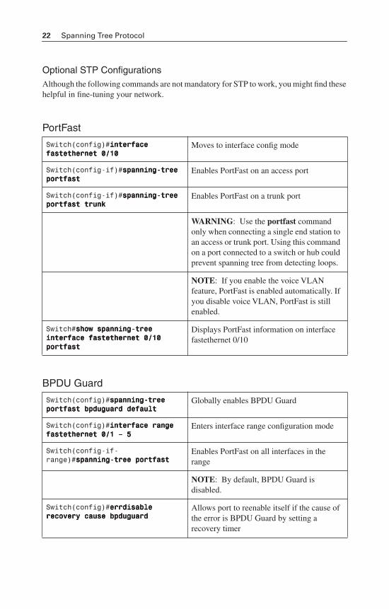
Optional STP ConfigurationsAlthough the following commands are not mandatory for STP to work, you might find these helpful in fine-tuning your network.
PortFast
BPDU Guard
Switch(config)#iiiinnnntttteeeerrrrffffaaaacccceeee ffffaaaasssstttteeeetttthhhheeeerrrrnnnneeeetttt 0000////11110000
Moves to interface config mode
Switch(config-if)#ssssppppaaaannnnnnnniiiinnnngggg----ttttrrrreeeeeeee ppppoooorrrrttttffffaaaasssstttt
Enables PortFast on an access port
Switch(config-if)#ssssppppaaaannnnnnnniiiinnnngggg----ttttrrrreeeeeeee ppppoooorrrrttttffffaaaasssstttt ttttrrrruuuunnnnkkkk
Enables PortFast on a trunk port
WARNING: Use the portfast command only when connecting a single end station to an access or trunk port. Using this command on a port connected to a switch or hub could prevent spanning tree from detecting loops.
NOTE: If you enable the voice VLAN feature, PortFast is enabled automatically. If you disable voice VLAN, PortFast is still enabled.
Switch#sssshhhhoooowwww ssssppppaaaannnnnnnniiiinnnngggg----ttttrrrreeeeeeee iiiinnnntttteeeerrrrffffaaaacccceeee ffffaaaasssstttteeeetttthhhheeeerrrrnnnneeeetttt 0000////11110000 ppppoooorrrrttttffffaaaasssstttt
Displays PortFast information on interface fastethernet 0/10
Switch(config)#ssssppppaaaannnnnnnniiiinnnngggg----ttttrrrreeeeeeee ppppoooorrrrttttffffaaaasssstttt bbbbppppdddduuuugggguuuuaaaarrrrdddd ddddeeeeffffaaaauuuulllltttt
Globally enables BPDU Guard
Switch(config)#iiiinnnntttteeeerrrrffffaaaacccceeee rrrraaaannnnggggeeee ffffaaaasssstttteeeetttthhhheeeerrrrnnnneeeetttt 0000////1111 –––– 5555
Enters interface range configuration mode
Switch(config-if-range)#ssssppppaaaannnnnnnniiiinnnngggg----ttttrrrreeeeeeee ppppoooorrrrttttffffaaaasssstttt
Enables PortFast on all interfaces in the range
NOTE: By default, BPDU Guard is disabled.
Switch(config)#eeeerrrrrrrrddddiiiissssaaaabbbblllleeee rrrreeeeccccoooovvvveeeerrrryyyy ccccaaaauuuusssseeee bbbbppppdddduuuugggguuuuaaaarrrrdddd
Allows port to reenable itself if the cause of the error is BPDU Guard by setting a recovery timer
Spanning Tree Protocol 23
BPDU Filtering
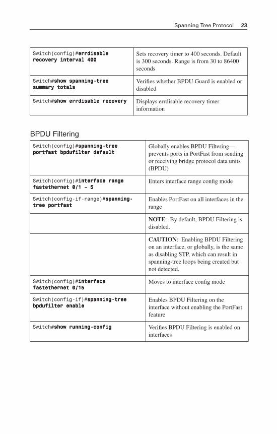
Switch(config)#eeeerrrrrrrrddddiiiissssaaaabbbblllleeee rrrreeeeccccoooovvvveeeerrrryyyy iiiinnnntttteeeerrrrvvvvaaaallll 444400000000
Sets recovery timer to 400 seconds. Default is 300 seconds. Range is from 30 to 86400 seconds
Switch#sssshhhhoooowwww ssssppppaaaannnnnnnniiiinnnngggg----ttttrrrreeeeeeee ssssuuuummmmmmmmaaaarrrryyyy ttttoooottttaaaallllssss
Verifies whether BPDU Guard is enabled or disabled
Switch#sssshhhhoooowwww eeeerrrrrrrrddddiiiissssaaaabbbblllleeee rrrreeeeccccoooovvvveeeerrrryyyy Displays errdisable recovery timer information
Switch(config)#ssssppppaaaannnnnnnniiiinnnngggg----ttttrrrreeeeeeee ppppoooorrrrttttffffaaaasssstttt bbbbppppdddduuuuffffiiiilllltttteeeerrrr ddddeeeeffffaaaauuuulllltttt
Globally enables BPDU Filtering—prevents ports in PortFast from sending or receiving bridge protocol data units (BPDU)
Switch(config)#iiiinnnntttteeeerrrrffffaaaacccceeee rrrraaaannnnggggeeee ffffaaaasssstttteeeetttthhhheeeerrrrnnnneeeetttt 0000////1111 –––– 5555
Enters interface range config mode
Switch(config-if-range)#ssssppppaaaannnnnnnniiiinnnngggg----ttttrrrreeeeeeee ppppoooorrrrttttffffaaaasssstttt
Enables PortFast on all interfaces in the range
NOTE: By default, BPDU Filtering is disabled.
CAUTION: Enabling BPDU Filtering on an interface, or globally, is the same as disabling STP, which can result in spanning-tree loops being created but not detected.
Switch(config)#iiiinnnntttteeeerrrrffffaaaacccceeee ffffaaaasssstttteeeetttthhhheeeerrrrnnnneeeetttt 0000////11115555
Moves to interface config mode
Switch(config-if)#ssssppppaaaannnnnnnniiiinnnngggg----ttttrrrreeeeeeee bbbbppppdddduuuuffffiiiilllltttteeeerrrr eeeennnnaaaabbbblllleeee
Enables BPDU Filtering on the interface without enabling the PortFast feature
Switch#sssshhhhoooowwww rrrruuuunnnnnnnniiiinnnngggg----ccccoooonnnnffffiiiigggg Verifies BPDU Filtering is enabled on interfaces
24 Spanning Tree Protocol
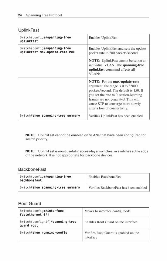
UplinkFast
NOTE: UplinkFast cannot be enabled on VLANs that have been configured for switch priority.
NOTE: UplinkFast is most useful in access-layer switches, or switches at the edge of the network. It is not appropriate for backbone devices.
BackboneFast
Root Guard
Switch(config)#ssssppppaaaannnnnnnniiiinnnngggg----ttttrrrreeeeeeee uuuupppplllliiiinnnnkkkkffffaaaasssstttt
Enables UplinkFast
Switch(config)#ssssppppaaaannnnnnnniiiinnnngggg----ttttrrrreeeeeeee uuuupppplllliiiinnnnkkkkffffaaaasssstttt mmmmaaaaxxxx----uuuuppppddddaaaatttteeee----rrrraaaatttteeee 222200000000
Enables UplinkFast and sets the update packet rate to 200 packets/second
NOTE: UplinkFast cannot be set on an individual VLAN. The spanning-tree uplinkfast command affects all VLANs.
NOTE: For the max-update-rateargument, the range is 0 to 32000 packets/second. The default is 150. If you set the rate to 0, station-learning frames are not generated. This will cause STP to converge more slowly after a loss of connectivity.
Switch#sssshhhhoooowwww ssssppppaaaannnnnnnniiiinnnngggg----ttttrrrreeeeeeee ssssuuuummmmmmmmaaaarrrryyyy Verifies UplinkFast has been enabled
Switch(config)#ssssppppaaaannnnnnnniiiinnnngggg----ttttrrrreeeeeeee bbbbaaaacccckkkkbbbboooonnnneeeeffffaaaasssstttt
Enables BackboneFast
Switch#sssshhhhoooowwww ssssppppaaaannnnnnnniiiinnnngggg----ttttrrrreeeeeeee ssssuuuummmmmmmmaaaarrrryyyy Verifies BackboneFast has been enabled
Switch(config)#iiiinnnntttteeeerrrrffffaaaacccceeee ffffaaaasssstttteeeetttthhhheeeerrrrnnnneeeetttt 0000////1111
Moves to interface config mode
Switch(config-if)#ssssppppaaaannnnnnnniiiinnnngggg----ttttrrrreeeeeeee gggguuuuaaaarrrrdddd rrrrooooooootttt
Enables Root Guard on the interface
Switch#sssshhhhoooowwww rrrruuuunnnnnnnniiiinnnngggg----ccccoooonnnnffffiiiigggg Verifies Root Guard is enabled on the interface
Spanning Tree Protocol 25
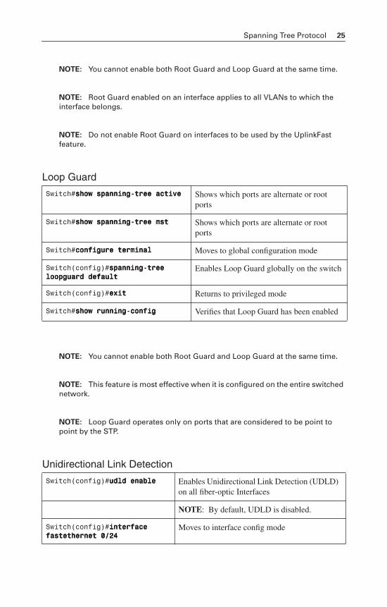
NOTE: You cannot enable both Root Guard and Loop Guard at the same time.
NOTE: Root Guard enabled on an interface applies to all VLANs to which the interface belongs.
NOTE: Do not enable Root Guard on interfaces to be used by the UplinkFast feature.
Loop Guard
NOTE: You cannot enable both Root Guard and Loop Guard at the same time.
NOTE: This feature is most effective when it is configured on the entire switched network.
NOTE: Loop Guard operates only on ports that are considered to be point to point by the STP.
Unidirectional Link Detection
Switch#sssshhhhoooowwww ssssppppaaaannnnnnnniiiinnnngggg----ttttrrrreeeeeeee aaaaccccttttiiiivvvveeee Shows which ports are alternate or root ports
Switch#sssshhhhoooowwww ssssppppaaaannnnnnnniiiinnnngggg----ttttrrrreeeeeeee mmmmsssstttt Shows which ports are alternate or root ports
Switch#ccccoooonnnnffffiiiigggguuuurrrreeee tttteeeerrrrmmmmiiiinnnnaaaallll Moves to global configuration mode
Switch(config)#ssssppppaaaannnnnnnniiiinnnngggg----ttttrrrreeeeeeee llllooooooooppppgggguuuuaaaarrrrdddd ddddeeeeffffaaaauuuulllltttt
Enables Loop Guard globally on the switch
Switch(config)#eeeexxxxiiiitttt Returns to privileged mode
Switch#sssshhhhoooowwww rrrruuuunnnnnnnniiiinnnngggg----ccccoooonnnnffffiiiigggg Verifies that Loop Guard has been enabled
Switch(config)#uuuuddddlllldddd eeeennnnaaaabbbblllleeee Enables Unidirectional Link Detection (UDLD) on all fiber-optic Interfaces
NOTE: By default, UDLD is disabled.
Switch(config)#iiiinnnntttteeeerrrrffffaaaacccceeee ffffaaaasssstttteeeetttthhhheeeerrrrnnnneeeetttt 0000////22224444
Moves to interface config mode
26 Spanning Tree Protocol
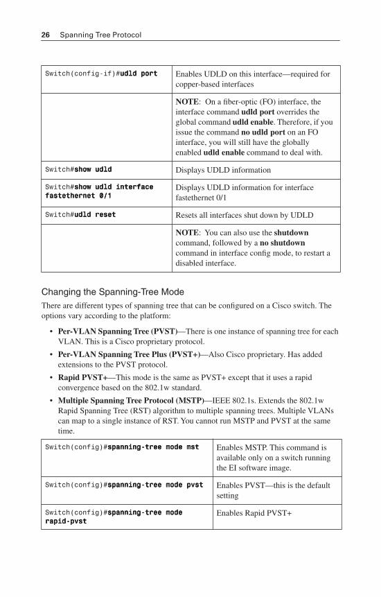
Changing the Spanning-Tree ModeThere are different types of spanning tree that can be configured on a Cisco switch. The options vary according to the platform:
• Per-VLAN Spanning Tree (PVST)—There is one instance of spanning tree for each VLAN. This is a Cisco proprietary protocol.
• Per-VLAN Spanning Tree Plus (PVST+)—Also Cisco proprietary. Has added extensions to the PVST protocol.
• Rapid PVST+—This mode is the same as PVST+ except that it uses a rapid convergence based on the 802.1w standard.
• Multiple Spanning Tree Protocol (MSTP)—IEEE 802.1s. Extends the 802.1w Rapid Spanning Tree (RST) algorithm to multiple spanning trees. Multiple VLANs can map to a single instance of RST. You cannot run MSTP and PVST at the same time.
Switch(config-if)#uuuuddddlllldddd ppppoooorrrrtttt Enables UDLD on this interface—required for copper-based interfaces
NOTE: On a fiber-optic (FO) interface, the interface command udld port overrides the global command udld enable. Therefore, if you issue the command no udld port on an FO interface, you will still have the globally enabled udld enable command to deal with.
Switch#sssshhhhoooowwww uuuuddddlllldddd Displays UDLD information
Switch#sssshhhhoooowwww uuuuddddlllldddd iiiinnnntttteeeerrrrffffaaaacccceeee ffffaaaasssstttteeeetttthhhheeeerrrrnnnneeeetttt 0000////1111
Displays UDLD information for interface fastethernet 0/1
Switch#uuuuddddlllldddd rrrreeeesssseeeetttt Resets all interfaces shut down by UDLD
NOTE: You can also use the shutdowncommand, followed by a no shutdown command in interface config mode, to restart a disabled interface.
Switch(config)#ssssppppaaaannnnnnnniiiinnnngggg----ttttrrrreeeeeeee mmmmooooddddeeee mmmmsssstttt Enables MSTP. This command is available only on a switch running the EI software image.
Switch(config)#ssssppppaaaannnnnnnniiiinnnngggg----ttttrrrreeeeeeee mmmmooooddddeeee ppppvvvvsssstttt Enables PVST—this is the default setting
Switch(config)#ssssppppaaaannnnnnnniiiinnnngggg----ttttrrrreeeeeeee mmmmooooddddeeee rrrraaaappppiiiidddd----ppppvvvvsssstttt
Enables Rapid PVST+
Spanning Tree Protocol 27
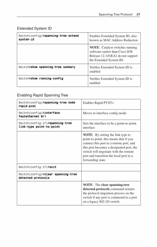
Extended System ID
Enabling Rapid Spanning Tree
Switch(config)#ssssppppaaaannnnnnnniiiinnnngggg----ttttrrrreeeeeeee eeeexxxxtttteeeennnndddd ssssyyyysssstttteeeemmmm----iiiidddd
Enables Extended System ID, also known as MAC Address Reduction
NOTE: Catalyst switches running software earlier than Cisco IOS Release 12.1(8)EA1 do not support the Extended System ID.
Switch#sssshhhhoooowwww ssssppppaaaannnnnnnniiiinnnngggg----ttttrrrreeeeeeee ssssuuuummmmmmmmaaaarrrryyyy Verifies Extended System ID is enabled
Switch#sssshhhhoooowwww rrrruuuunnnnnnnniiiinnnngggg----ccccoooonnnnffffiiiigggg Verifies Extended System ID is enabled
Switch(config)#ssssppppaaaannnnnnnniiiinnnngggg----ttttrrrreeeeeeee mmmmooooddddeeee rrrraaaappppiiiidddd----ppppvvvvsssstttt
Enables Rapid PVST+
Switch(config)#iiiinnnntttteeeerrrrffffaaaacccceeee ffffaaaasssstttteeeetttthhhheeeerrrrnnnneeeetttt 0000////1111
Moves to interface config mode
Switch(config-if)#ssssppppaaaannnnnnnniiiinnnngggg----ttttrrrreeeeeeee lllliiiinnnnkkkk----ttttyyyyppppeeee ppppooooiiiinnnntttt----ttttoooo----ppppooooiiiinnnntttt
Sets the interface to be a point-to-point interface
NOTE: By setting the link type to point-to-point, this means that if you connect this port to a remote port, and this port becomes a designated port, the switch will negotiate with the remote port and transition the local port to a forwarding state.
Switch(config-if)#eeeexxxxiiiitttt
Switch(config)#cccclllleeeeaaaarrrr ssssppppaaaannnnnnnniiiinnnngggg----ttttrrrreeeeeeee ddddeeeetttteeeecccctttteeeedddd----pppprrrroooottttooooccccoooollllssss
NOTE: The clear spanning-tree detected-protocols command restarts the protocol migration process on the switch if any port is connected to a port on a legacy 802.1D switch.
28 Spanning Tree Protocol
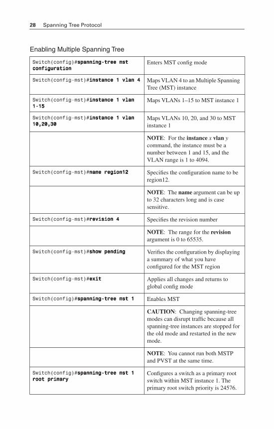
Enabling Multiple Spanning Tree
Switch(config)#ssssppppaaaannnnnnnniiiinnnngggg----ttttrrrreeeeeeee mmmmsssstttt ccccoooonnnnffffiiiigggguuuurrrraaaattttiiiioooonnnn
Enters MST config mode
Switch(config-mst)#iiiinnnnssssttttaaaannnncccceeee 1111 vvvvllllaaaannnn 4444 Maps VLAN 4 to an Multiple Spanning Tree (MST) instance
Switch(config-mst)#iiiinnnnssssttttaaaannnncccceeee 1111 vvvvllllaaaannnn 1111----11115555
Maps VLANs 1–15 to MST instance 1
Switch(config-mst)#iiiinnnnssssttttaaaannnncccceeee 1111 vvvvllllaaaannnn 11110000,,,,22220000,,,,33330000
Maps VLANs 10, 20, and 30 to MST instance 1
NOTE: For the instance x vlan ycommand, the instance must be a number between 1 and 15, and the VLAN range is 1 to 4094.
Switch(config-mst)#nnnnaaaammmmeeee rrrreeeeggggiiiioooonnnn11112222 Specifies the configuration name to be region12.
NOTE: The name argument can be up to 32 characters long and is case sensitive.
Switch(config-mst)#rrrreeeevvvviiiissssiiiioooonnnn 4444 Specifies the revision number
NOTE: The range for the revisionargument is 0 to 65535.
Switch(config-mst)#sssshhhhoooowwww ppppeeeennnnddddiiiinnnngggg Verifies the configuration by displaying a summary of what you have configured for the MST region
Switch(config-mst)#eeeexxxxiiiitttt Applies all changes and returns to global config mode
Switch(config)#ssssppppaaaannnnnnnniiiinnnngggg----ttttrrrreeeeeeee mmmmsssstttt 1111 Enables MST
CAUTION: Changing spanning-tree modes can disrupt traffic because all spanning-tree instances are stopped for the old mode and restarted in the new mode.
NOTE: You cannot run both MSTP and PVST at the same time.
Switch(config)#ssssppppaaaannnnnnnniiiinnnngggg----ttttrrrreeeeeeee mmmmsssstttt 1111 rrrrooooooootttt pppprrrriiiimmmmaaaarrrryyyy
Configures a switch as a primary root switch within MST instance 1. The primary root switch priority is 24576.
Spanning Tree Protocol 29
Verifying MST
Troubleshooting Spanning Tree
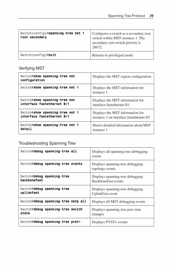
Switch(config)#ssssppppaaaannnnnnnniiiinnnngggg----ttttrrrreeeeeeee mmmmsssstttt 1111 rrrrooooooootttt sssseeeeccccoooonnnnddddaaaarrrryyyy
Configures a switch as a secondary root switch within MST instance 1. The secondary root switch priority is 28672.
Switch(config)#eeeexxxxiiiitttt Returns to privileged mode
Switch#sssshhhhoooowwww ssssppppaaaannnnnnnniiiinnnngggg----ttttrrrreeeeeeee mmmmsssstttt ccccoooonnnnffffiiiigggguuuurrrraaaattttiiiioooonnnn
Displays the MST region configuration
Switch#sssshhhhoooowwww ssssppppaaaannnnnnnniiiinnnngggg----ttttrrrreeeeeeee mmmmsssstttt 1111 Displays the MST information for instance 1
Switch#sssshhhhoooowwww ssssppppaaaannnnnnnniiiinnnngggg----ttttrrrreeeeeeee mmmmsssstttt iiiinnnntttteeeerrrrffffaaaacccceeee ffffaaaasssstttteeeetttthhhheeeerrrrnnnneeeetttt 0000////1111
Displays the MST information for interface fastethernet 0/1
Switch#sssshhhhoooowwww ssssppppaaaannnnnnnniiiinnnngggg----ttttrrrreeeeeeee mmmmsssstttt 1111 iiiinnnntttteeeerrrrffffaaaacccceeee ffffaaaasssstttteeeetttthhhheeeerrrrnnnneeeetttt 0000////1111
Displays the MST information for instance 1 on interface fastethernet 0/1
Switch#sssshhhhoooowwww ssssppppaaaannnnnnnniiiinnnngggg----ttttrrrreeeeeeee mmmmsssstttt 1111 ddddeeeettttaaaaiiiillll
Shows detailed information about MST instance 1
Switch#ddddeeeebbbbuuuugggg ssssppppaaaannnnnnnniiiinnnngggg----ttttrrrreeeeeeee aaaallllllll Displays all spanning-tree debugging events
Switch#ddddeeeebbbbuuuugggg ssssppppaaaannnnnnnniiiinnnngggg----ttttrrrreeeeeeee eeeevvvveeeennnnttttssss Displays spanning-tree debugging topology events
Switch#ddddeeeebbbbuuuugggg ssssppppaaaannnnnnnniiiinnnngggg----ttttrrrreeeeeeee bbbbaaaacccckkkkbbbboooonnnneeeeffffaaaasssstttt
Displays spanning-tree debugging BackboneFast events
Switch#ddddeeeebbbbuuuugggg ssssppppaaaannnnnnnniiiinnnngggg----ttttrrrreeeeeeee uuuupppplllliiiinnnnkkkkffffaaaasssstttt
Displays spanning-tree debugging UplinkFast event
Switch#ddddeeeebbbbuuuugggg ssssppppaaaannnnnnnniiiinnnngggg----ttttrrrreeeeeeee mmmmssssttttpppp aaaallllllll Displays all MST debugging events
Switch#ddddeeeebbbbuuuugggg ssssppppaaaannnnnnnniiiinnnngggg----ttttrrrreeeeeeee sssswwwwiiiittttcccchhhh ssssttttaaaatttteeee
Displays spanning-tree port state changes
Switch#ddddeeeebbbbuuuugggg ssssppppaaaannnnnnnniiiinnnngggg----ttttrrrreeeeeeee ppppvvvvsssstttt++++ Displays PVST+ events
30 Spanning Tree Protocol
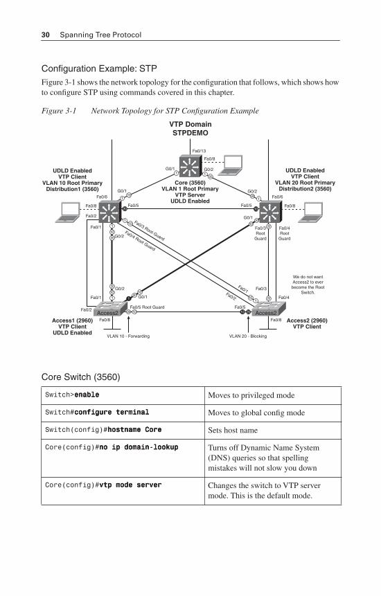
Configuration Example: STPFigure 3-1 shows the network topology for the configuration that follows, which shows how to configure STP using commands covered in this chapter.
Figure 3-1 Network Topology for STP Configuration Example
Core Switch (3560)
Switch>eeeennnnaaaabbbblllleeee Moves to privileged mode
Switch#ccccoooonnnnffffiiiigggguuuurrrreeee tttteeeerrrrmmmmiiiinnnnaaaallll Moves to global config mode
Switch(config)#hhhhoooossssttttnnnnaaaammmmeeee CCCCoooorrrreeee Sets host name
Core(config)#nnnnoooo iiiipppp ddddoooommmmaaaaiiiinnnn----llllooooooookkkkuuuupppp Turns off Dynamic Name System (DNS) queries so that spelling mistakes will not slow you down
Core(config)#vvvvttttpppp mmmmooooddddeeee sssseeeerrrrvvvveeeerrrr Changes the switch to VTP server mode. This is the default mode.
VTP DomainSTPDEMO
Access2 Access2
Fa0/13
Fa0/6
Fa0/8
Fa0/6
Fa0/5
Fa0/3 Root Guard
Fa0/2
Fa0/1
Fa0/4 Root Guard
G0/1
G0/1 G0/2
G0/2
G0/1
Fa0/5
Fa0/5 Root Guard Fa0/5
Fa0/8
Fa0/2
Fa0/2
Fa0/8 Fa0/8
Fa0/1
Fa0/1
G0/2
G0/2
G0/1
Fa0/3
Fa0/4
Fa0/3Root
Guard
Fa0/4Root
Guard
We do not wantAccess2 to everbecome the Root
Switch.
VLAN 20 - Blocking
Core (3560)VLAN 1 Root Primary
VTP ServerUDLD Enabled
Access1 (2960)VTP Client
UDLD Enabled
UDLD EnabledVTP Client
VLAN 10 Root PrimaryDistribution1 (3560)
Access2 (2960)VTP Client
UDLD EnabledVTP Client
VLAN 20 Root PrimaryDistribution2 (3560)
Fa0/8
1
10 20
20 10
1
1
1
1
1
11
1
10
10
10
10
10
10
10 20
20
20
20
20
1020
20
20
20
VLAN 10 - Forwarding
Spanning Tree Protocol 31
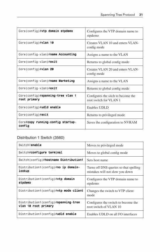
Distribution 1 Switch (3560)
Core(config)#vvvvttttpppp ddddoooommmmaaaaiiiinnnn ssssttttppppddddeeeemmmmoooo Configures the VTP domain name to stpdemo
Core(config)#vvvvllllaaaannnn 11110000 Creates VLAN 10 and enters VLAN-config mode
Core(config-vlan)#nnnnaaaammmmeeee AAAAccccccccoooouuuunnnnttttiiiinnnngggg Assigns a name to the VLAN
Core(config-vlan)#eeeexxxxiiiitttt Returns to global config mode
Core(config)#vvvvllllaaaannnn 22220000 Creates VLAN 20 and enters VLAN-config mode
Core(config-vlan)#nnnnaaaammmmeeee MMMMaaaarrrrkkkkeeeettttiiiinnnngggg Assigns a name to the VLAN
Core(config-vlan)#eeeexxxxiiiitttt Returns to global config mode
Core(config)#ssssppppaaaannnnnnnniiiinnnngggg----ttttrrrreeeeeeee vvvvllllaaaannnn 1111 rrrrooooooootttt pppprrrriiiimmmmaaaarrrryyyy
Configures the sitch to become the root switch for VLAN 1
Core(config)#uuuuddddlllldddd eeeennnnaaaabbbblllleeee Enables UDLD
Core(config)#eeeexxxxiiiitttt Returns to privileged mode
Core#ccccooooppppyyyy rrrruuuunnnnnnnniiiinnnngggg----ccccoooonnnnffffiiiigggg ssssttttaaaarrrrttttuuuupppp----ccccoooonnnnffffiiiigggg
Saves the configuration to NVRAM
Switch>eeeennnnaaaabbbblllleeee Moves to privileged mode
Switch#ccccoooonnnnffffiiiigggguuuurrrreeee tttteeeerrrrmmmmiiiinnnnaaaallll Moves to global config mode
Switch(config)#hhhhoooossssttttnnnnaaaammmmeeee DDDDiiiissssttttrrrriiiibbbbuuuuttttiiiioooonnnn1111 Sets host name
Distribution1(config)#nnnnoooo iiiipppp ddddoooommmmaaaaiiiinnnn----llllooooooookkkkuuuupppp
Turns off DNS queries so that spelling mistakes will not slow you down
Distribution1(config)#vvvvttttpppp ddddoooommmmaaaaiiiinnnn ssssttttppppddddeeeemmmmoooo
Configures the VTP domain name to stpdemo
Distribution1(config)#vvvvttttpppp mmmmooooddddeeee cccclllliiiieeeennnntttt Changes the switch to VTP client mode
Distribution1(config)#ssssppppaaaannnnnnnniiiinnnngggg----ttttrrrreeeeeeee vvvvllllaaaannnn 11110000 rrrrooooooootttt pppprrrriiiimmmmaaaarrrryyyy
Configures the switch to become the root switch of VLAN 10
Distribution1(config)#uuuuddddlllldddd eeeennnnaaaabbbblllleeee Enables UDLD on all FO interfaces
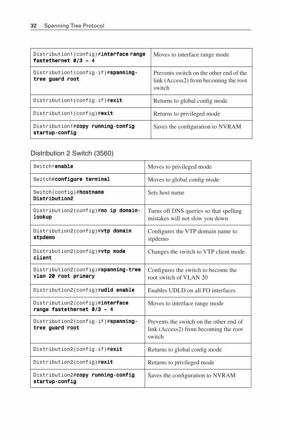
32 Spanning Tree Protocol
Distribution 2 Switch (3560)
Distribution1(config)#iiiinnnntttteeeerrrrffffaaaacccceeee rrrraaaannnnggggeeee ffffaaaasssstttteeeetttthhhheeeerrrrnnnneeeetttt 0000////3333 –––– 4444
Moves to interface range mode
Distribution1(config-if)#ssssppppaaaannnnnnnniiiinnnngggg----ttttrrrreeeeeeee gggguuuuaaaarrrrdddd rrrrooooooootttt
Prevents switch on the other end of the link (Access2) from becoming the root switch
Distribution1(config-if)#eeeexxxxiiiitttt Returns to global config mode
Distribution1(config)#eeeexxxxiiiitttt Returns to privileged mode
Distribution1#ccccooooppppyyyy rrrruuuunnnnnnnniiiinnnngggg----ccccoooonnnnffffiiiigggg ssssttttaaaarrrrttttuuuupppp----ccccoooonnnnffffiiiigggg
Saves the configuration to NVRAM
Switch>eeeennnnaaaabbbblllleeee Moves to privileged mode
Switch#ccccoooonnnnffffiiiigggguuuurrrreeee tttteeeerrrrmmmmiiiinnnnaaaallll Moves to global config mode
Switch(config)#hhhhoooossssttttnnnnaaaammmmeeee DDDDiiiissssttttrrrriiiibbbbuuuuttttiiiioooonnnn2222
Sets host name
Distribution2(config)#nnnnoooo iiiipppp ddddoooommmmaaaaiiiinnnn----llllooooooookkkkuuuupppp
Turns off DNS queries so that spelling mistakes will not slow you down
Distribution2(config)#vvvvttttpppp ddddoooommmmaaaaiiiinnnn ssssttttppppddddeeeemmmmoooo
Configures the VTP domain name to stpdemo
Distribution2(config)#vvvvttttpppp mmmmooooddddeeee cccclllliiiieeeennnntttt
Changes the switch to VTP client mode
Distribution2(config)#ssssppppaaaannnnnnnniiiinnnngggg----ttttrrrreeeeeeee vvvvllllaaaannnn 22220000 rrrrooooooootttt pppprrrriiiimmmmaaaarrrryyyy
Configures the switch to become the root switch of VLAN 20
Distribution2(config)#uuuuddddlllldddd eeeennnnaaaabbbblllleeee Enables UDLD on all FO interfaces
Distribution2(config)#iiiinnnntttteeeerrrrffffaaaacccceeee rrrraaaannnnggggeeee ffffaaaasssstttteeeetttthhhheeeerrrrnnnneeeetttt 0000////3333 –––– 4444
Moves to interface range mode
Distribution2(config-if)#ssssppppaaaannnnnnnniiiinnnngggg----ttttrrrreeeeeeee gggguuuuaaaarrrrdddd rrrrooooooootttt
Prevents the switch on the other end of link (Access2) from becoming the root switch
Distribution2(config-if)#eeeexxxxiiiitttt Returns to global config mode
Distribution2(config)#eeeexxxxiiiitttt Returns to privileged mode
Distribution2#ccccooooppppyyyy rrrruuuunnnnnnnniiiinnnngggg----ccccoooonnnnffffiiiigggg ssssttttaaaarrrrttttuuuupppp----ccccoooonnnnffffiiiigggg
Saves the configuration to NVRAM
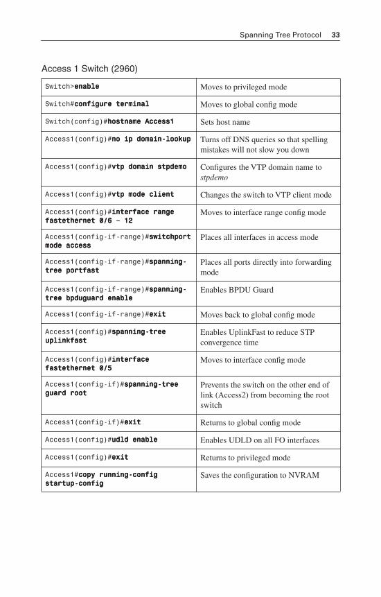
Spanning Tree Protocol 33
Access 1 Switch (2960)
Switch>eeeennnnaaaabbbblllleeee Moves to privileged mode
Switch#ccccoooonnnnffffiiiigggguuuurrrreeee tttteeeerrrrmmmmiiiinnnnaaaallll Moves to global config mode
Switch(config)#hhhhoooossssttttnnnnaaaammmmeeee AAAAcccccccceeeessssssss1111 Sets host name
Access1(config)#nnnnoooo iiiipppp ddddoooommmmaaaaiiiinnnn----llllooooooookkkkuuuupppp Turns off DNS queries so that spelling mistakes will not slow you down
Access1(config)#vvvvttttpppp ddddoooommmmaaaaiiiinnnn ssssttttppppddddeeeemmmmoooo Configures the VTP domain name to stpdemo
Access1(config)#vvvvttttpppp mmmmooooddddeeee cccclllliiiieeeennnntttt Changes the switch to VTP client mode
Access1(config)#iiiinnnntttteeeerrrrffffaaaacccceeee rrrraaaannnnggggeeee ffffaaaasssstttteeeetttthhhheeeerrrrnnnneeeetttt 0000////6666 –––– 11112222
Moves to interface range config mode
Access1(config-if-range)#sssswwwwiiiittttcccchhhhppppoooorrrrtttt mmmmooooddddeeee aaaacccccccceeeessssssss
Places all interfaces in access mode
Access1(config-if-range)#ssssppppaaaannnnnnnniiiinnnngggg----ttttrrrreeeeeeee ppppoooorrrrttttffffaaaasssstttt
Places all ports directly into forwarding mode
Access1(config-if-range)#ssssppppaaaannnnnnnniiiinnnngggg----ttttrrrreeeeeeee bbbbppppdddduuuugggguuuuaaaarrrrdddd eeeennnnaaaabbbblllleeee
Enables BPDU Guard
Access1(config-if-range)#eeeexxxxiiiitttt Moves back to global config mode
Access1(config)#ssssppppaaaannnnnnnniiiinnnngggg----ttttrrrreeeeeeee uuuupppplllliiiinnnnkkkkffffaaaasssstttt
Enables UplinkFast to reduce STP convergence time
Access1(config)#iiiinnnntttteeeerrrrffffaaaacccceeee ffffaaaasssstttteeeetttthhhheeeerrrrnnnneeeetttt 0000////5555
Moves to interface config mode
Access1(config-if)#ssssppppaaaannnnnnnniiiinnnngggg----ttttrrrreeeeeeee gggguuuuaaaarrrrdddd rrrrooooooootttt
Prevents the switch on the other end of link (Access2) from becoming the root switch
Access1(config-if)#eeeexxxxiiiitttt Returns to global config mode
Access1(config)#uuuuddddlllldddd eeeennnnaaaabbbblllleeee Enables UDLD on all FO interfaces
Access1(config)#eeeexxxxiiiitttt Returns to privileged mode
Access1#ccccooooppppyyyy rrrruuuunnnnnnnniiiinnnngggg----ccccoooonnnnffffiiiigggg ssssttttaaaarrrrttttuuuupppp----ccccoooonnnnffffiiiigggg
Saves the configuration to NVRAM
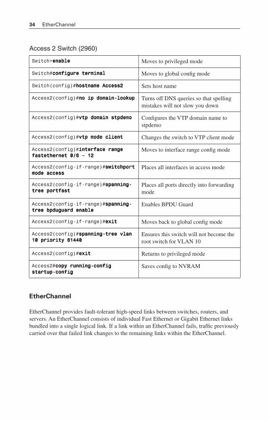
34 EtherChannel
Access 2 Switch (2960)
EtherChannel
EtherChannel provides fault-tolerant high-speed links between switches, routers, and servers. An EtherChannel consists of individual Fast Ethernet or Gigabit Ethernet links bundled into a single logical link. If a link within an EtherChannel fails, traffic previously carried over that failed link changes to the remaining links within the EtherChannel.
Switch>eeeennnnaaaabbbblllleeee Moves to privileged mode
Switch#ccccoooonnnnffffiiiigggguuuurrrreeee tttteeeerrrrmmmmiiiinnnnaaaallll Moves to global config mode
Switch(config)#hhhhoooossssttttnnnnaaaammmmeeee AAAAcccccccceeeessssssss2222 Sets host name
Access2(config)#nnnnoooo iiiipppp ddddoooommmmaaaaiiiinnnn----llllooooooookkkkuuuupppp Turns off DNS queries so that spelling mistakes will not slow you down
Access2(config)#vvvvttttpppp ddddoooommmmaaaaiiiinnnn ssssttttppppddddeeeemmmmoooo Configures the VTP domain name to stpdemo
Access2(config)#vvvvttttpppp mmmmooooddddeeee cccclllliiiieeeennnntttt Changes the switch to VTP client mode
Access2(config)#iiiinnnntttteeeerrrrffffaaaacccceeee rrrraaaannnnggggeeee ffffaaaasssstttteeeetttthhhheeeerrrrnnnneeeetttt 0000////6666 –––– 11112222
Moves to interface range config mode
Access2(config-if-range)#sssswwwwiiiittttcccchhhhppppoooorrrrtttt mmmmooooddddeeee aaaacccccccceeeessssssss
Places all interfaces in access mode
Access2(config-if-range)#ssssppppaaaannnnnnnniiiinnnngggg----ttttrrrreeeeeeee ppppoooorrrrttttffffaaaasssstttt
Places all ports directly into forwarding mode
Access2(config-if-range)#ssssppppaaaannnnnnnniiiinnnngggg----ttttrrrreeeeeeee bbbbppppdddduuuugggguuuuaaaarrrrdddd eeeennnnaaaabbbblllleeee
Enables BPDU Guard
Access2(config-if-range)#eeeexxxxiiiitttt Moves back to global config mode
Access2(config)#ssssppppaaaannnnnnnniiiinnnngggg----ttttrrrreeeeeeee vvvvllllaaaannnn 11110000 pppprrrriiiioooorrrriiiittttyyyy 66661111444444440000
Ensures this switch will not become the root switch for VLAN 10
Access2(config)#eeeexxxxiiiitttt Returns to privileged mode
Access2#ccccooooppppyyyy rrrruuuunnnnnnnniiiinnnngggg----ccccoooonnnnffffiiiigggg ssssttttaaaarrrrttttuuuupppp----ccccoooonnnnffffiiiigggg
Saves config to NVRAM
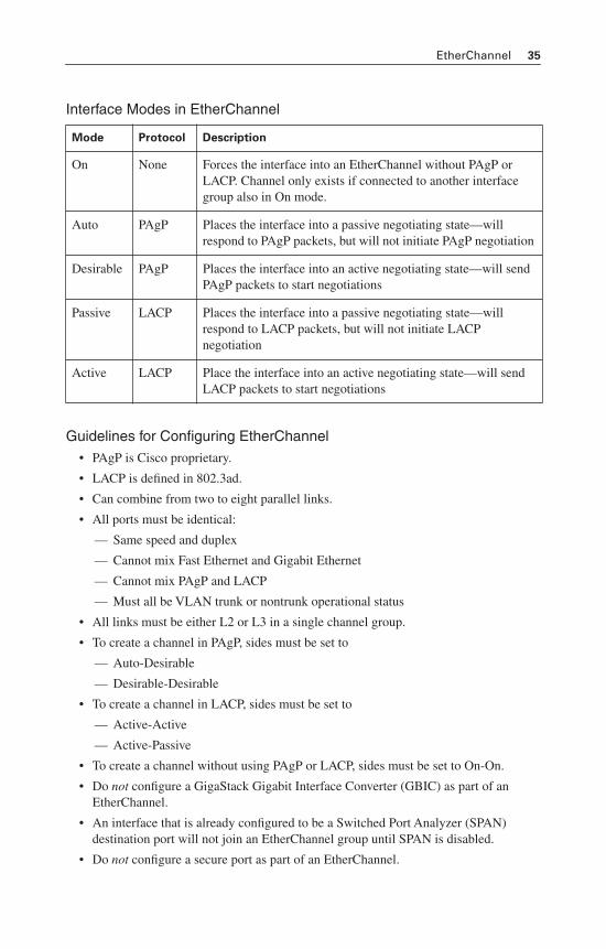
EtherChannel 35
Interface Modes in EtherChannel
Guidelines for Configuring EtherChannel• PAgP is Cisco proprietary.
• LACP is defined in 802.3ad.
• Can combine from two to eight parallel links.
• All ports must be identical:
— Same speed and duplex
— Cannot mix Fast Ethernet and Gigabit Ethernet
— Cannot mix PAgP and LACP
— Must all be VLAN trunk or nontrunk operational status
• All links must be either L2 or L3 in a single channel group.
• To create a channel in PAgP, sides must be set to
— Auto-Desirable
— Desirable-Desirable
• To create a channel in LACP, sides must be set to
— Active-Active
— Active-Passive
• To create a channel without using PAgP or LACP, sides must be set to On-On.
• Do not configure a GigaStack Gigabit Interface Converter (GBIC) as part of an EtherChannel.
• An interface that is already configured to be a Switched Port Analyzer (SPAN) destination port will not join an EtherChannel group until SPAN is disabled.
• Do not configure a secure port as part of an EtherChannel.
Mode Protocol Description
On None Forces the interface into an EtherChannel without PAgP or LACP. Channel only exists if connected to another interface group also in On mode.
Auto PAgP Places the interface into a passive negotiating state—will respond to PAgP packets, but will not initiate PAgP negotiation
Desirable PAgP Places the interface into an active negotiating state—will send PAgP packets to start negotiations
Passive LACP Places the interface into a passive negotiating state—will respond to LACP packets, but will not initiate LACP negotiation
Active LACP Place the interface into an active negotiating state—will send LACP packets to start negotiations
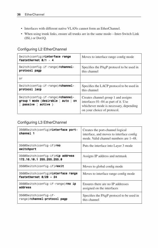
36 EtherChannel
• Interfaces with different native VLANs cannot form an EtherChannel.
• When using trunk links, ensure all trunks are in the same mode—Inter-Switch Link (ISL) or Dot1Q.
Configuring L2 EtherChannel
Configuring L3 EtherChannel
Switch(config)#iiiinnnntttteeeerrrrffffaaaacccceeee rrrraaaannnnggggeeee ffffaaaasssstttteeeetttthhhheeeerrrrnnnneeeetttt 0000////1111 ---- 4444
Moves to interface range config mode
Switch(config-if-range)#cccchhhhaaaannnnnnnneeeellll----pppprrrroooottttooooccccoooollll ppppaaaaggggpppp
Specifies the PAgP protocol to be used in this channel
or
Switch(config-if-range)#cccchhhhaaaannnnnnnneeeellll----pppprrrroooottttooooccccoooollll llllaaaaccccpppp
Specifies the LACP protocol to be used in this channel
Switch(config-if-range)#cccchhhhaaaannnnnnnneeeellll----ggggrrrroooouuuupppp 1111 mmmmooooddddeeee {ddddeeeessssiiiirrrraaaabbbblllleeee | aaaauuuuttttoooo | oooonnnn | ppppaaaassssssssiiiivvvveeee | aaaaccccttttiiiivvvveeee }
Creates channel group 1 and assigns interfaces 01–04 as part of it. Use whichever mode is necessary, depending on your choice of protocol.
3560Switch(config)#iiiinnnntttteeeerrrrffffaaaacccceeee ppppoooorrrrtttt----cccchhhhaaaannnnnnnneeeellll 1111
Creates the port-channel logical interface, and moves to interface config mode. Valid channel numbers are 1–48.
3560Switch(config-if)#nnnnoooo sssswwwwiiiittttcccchhhhppppoooorrrrtttt
Puts the interface into Layer 3 mode
3560Switch(config-if)#iiiipppp aaaaddddddddrrrreeeessssssss 111177772222....11116666....11110000....1111 222255555555....222255555555....222255555555....0000
Assigns IP address and netmask
3560Switch(config-if)#eeeexxxxiiiitttt Moves to global config mode
3560Switch(config)#iiiinnnntttteeeerrrrffffaaaacccceeee rrrraaaannnnggggeeee ffffaaaasssstttteeeetttthhhheeeerrrrnnnneeeetttt 0000////22220000 –––– 22224444
Moves to interface range config mode
3560Switch(config-if-range)#nnnnoooo iiiipppp aaaaddddddddrrrreeeessssssss
Ensures there are no IP addresses assigned on the interfaces
3560Switch(config-if-range)#cccchhhhaaaannnnnnnneeeellll----pppprrrroooottttooooccccoooollll ppppaaaaggggpppp
Specifies the PAgP protocol to be used in this channel
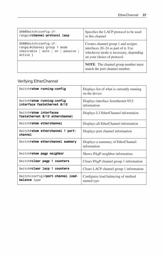
EtherChannel 37
Verifying EtherChannel
3560Switch(config-if-range)#cccchhhhaaaannnnnnnneeeellll----pppprrrroooottttooooccccoooollll llllaaaaccccpppp
Specifies the LACP protocol to be used in this channel
3560Switch(config-if-range)#channel-group 1 mode {desirable | auto | on | passive | active }
Creates channel group 1 and assigns interfaces 20–24 as part of it. Use whichever mode is necessary, depending on your choice of protocol.
NOTE: The channel group number must match the port channel number.
Switch#sssshhhhoooowwww rrrruuuunnnnnnnniiiinnnngggg----ccccoooonnnnffffiiiigggg Displays list of what is currently running on the device
Switch#sssshhhhoooowwww rrrruuuunnnnnnnniiiinnnngggg----ccccoooonnnnffffiiiigggg iiiinnnntttteeeerrrrffffaaaacccceeee ffffaaaasssstttteeeetttthhhheeeerrrrnnnneeeetttt 0000////11112222
Displays interface fastethernet 0/12 information
Switch#sssshhhhoooowwww iiiinnnntttteeeerrrrffffaaaacccceeeessss ffffaaaasssstttteeeetttthhhheeeerrrrnnnneeeetttt 0000////11112222 eeeetttthhhheeeerrrrcccchhhhaaaannnnnnnneeeellll
Displays L3 EtherChannel information
Switch#sssshhhhoooowwww eeeetttthhhheeeerrrrcccchhhhaaaannnnnnnneeeellll Displays all EtherChannel information
Switch#sssshhhhoooowwww eeeetttthhhheeeerrrrcccchhhhaaaannnnnnnneeeellll 1111 ppppoooorrrrtttt----cccchhhhaaaannnnnnnneeeellll
Displays port channel information
Switch#sssshhhhoooowwww eeeetttthhhheeeerrrrcccchhhhaaaannnnnnnneeeellll ssssuuuummmmmmmmaaaarrrryyyy Displays a summary of EtherChannel information
Switch#sssshhhhoooowwww ppppaaaaggggpppp nnnneeeeiiiigggghhhhbbbboooorrrr Shows PAgP neighbor information
Switch#cccclllleeeeaaaarrrr ppppaaaaggggpppp 1111 ccccoooouuuunnnntttteeeerrrrssss Clears PAgP channel group 1 information
Switch#cccclllleeeeaaaarrrr llllaaaaccccpppp 1111 ccccoooouuuunnnntttteeeerrrrssss Clears LACP channel group 1 information
Switch(config)#ppppoooorrrrtttt----cccchhhhaaaannnnnnnneeeellll llllooooaaaadddd----bbbbaaaallllaaaannnncccceeee type
Configures load balancing of method named type
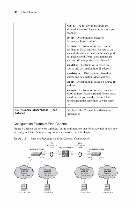
38 EtherChannel
Configuration Example: EtherChannelFigure 3-2 shows the network topology for the configuration that follows, which shows how to configure EtherChannel using commands covered in this chapter.
Figure 3-2 Network Topology for EtherChannel Configuration
NOTE: The following methods are allowed when load balancing across a port channel:
dst-ip Distribution is based on destination host IP address.
dst-mac Distribution is based on the destination MAC address. Packets to the same destination are sent on the same port, but packets to different destinations are sent on different ports in the channel.
src-dst-ip Distribution is based on source and destination host IP address.
src-dst-mac Distribution is based on source and destination MAC address.
src-ip Distribution is based on source IP address.
src-mac Distribution is based on source MAC address. Packets from different hosts use different ports in the channel, but packets from the same host use the same port.
Switch#sssshhhhoooowwww eeeetttthhhheeeerrrrcccchhhhaaaannnnnnnneeeellll llllooooaaaadddd----bbbbaaaallllaaaannnncccceeee
Displays EtherChannel load-balancing information
AccountingVLAN 10Fa 0/5-8
172.16.10.0/24
FECIEEE 802.1q
Trunk
Fa0/1
Fa0/2
Fa0/1
Fa0/2
Fa0/3
Fa0/4
Fa0/1
Fa0/12Fa0/6Fa0/12Fa0/6
Fa0/2
FECIEEE 802.1q
Trunk
172.16.10.2/24
WS1
MarketingVLAN 20Fa 0/9-12
172.16.20.0/24
172.16.20.2/24
WS2
AccountingVLAN 10Fa 0/5-8
172.16.10.0/24
172.16.10.3/24
WS3
MarketingVLAN 20Fa 0/9-12
172.16.20.0/24
172.16.20.3/24
WS4
DLSwitch (3560)ALSwitch1 (2960) ALSwitch2 (2960)
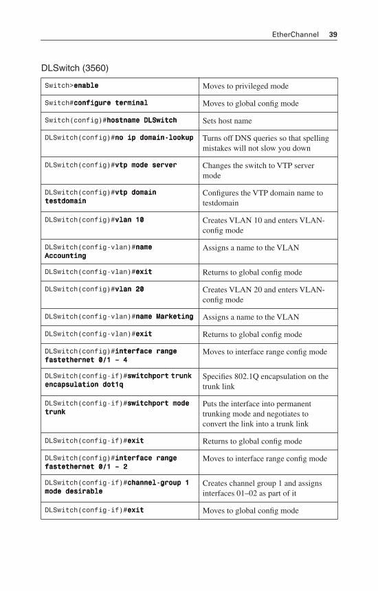
EtherChannel 39
DLSwitch (3560)
Switch>eeeennnnaaaabbbblllleeee Moves to privileged mode
Switch#ccccoooonnnnffffiiiigggguuuurrrreeee tttteeeerrrrmmmmiiiinnnnaaaallll Moves to global config mode
Switch(config)#hhhhoooossssttttnnnnaaaammmmeeee DDDDLLLLSSSSwwwwiiiittttcccchhhh Sets host name
DLSwitch(config)#nnnnoooo iiiipppp ddddoooommmmaaaaiiiinnnn----llllooooooookkkkuuuupppp Turns off DNS queries so that spelling mistakes will not slow you down
DLSwitch(config)#vvvvttttpppp mmmmooooddddeeee sssseeeerrrrvvvveeeerrrr Changes the switch to VTP server mode
DLSwitch(config)#vvvvttttpppp ddddoooommmmaaaaiiiinnnn tttteeeessssttttddddoooommmmaaaaiiiinnnn
Configures the VTP domain name to testdomain
DLSwitch(config)#vvvvllllaaaannnn 11110000 Creates VLAN 10 and enters VLAN-config mode
DLSwitch(config-vlan)#nnnnaaaammmmeeee AAAAccccccccoooouuuunnnnttttiiiinnnngggg
Assigns a name to the VLAN
DLSwitch(config-vlan)#eeeexxxxiiiitttt Returns to global config mode
DLSwitch(config)#vvvvllllaaaannnn 22220000 Creates VLAN 20 and enters VLAN-config mode
DLSwitch(config-vlan)#nnnnaaaammmmeeee MMMMaaaarrrrkkkkeeeettttiiiinnnngggg Assigns a name to the VLAN
DLSwitch(config-vlan)#eeeexxxxiiiitttt Returns to global config mode
DLSwitch(config)#iiiinnnntttteeeerrrrffffaaaacccceeee rrrraaaannnnggggeeee ffffaaaasssstttteeeetttthhhheeeerrrrnnnneeeetttt 0000////1111 –––– 4444
Moves to interface range config mode
DLSwitch(config-if)#sssswwwwiiiittttcccchhhhppppoooorrrrtttt ttttrrrruuuunnnnkkkk eeeennnnccccaaaappppssssuuuullllaaaattttiiiioooonnnn ddddooootttt1111qqqq
Specifies 802.1Q encapsulation on the trunk link
DLSwitch(config-if)#sssswwwwiiiittttcccchhhhppppoooorrrrtttt mmmmooooddddeeee ttttrrrruuuunnnnkkkk
Puts the interface into permanent trunking mode and negotiates to convert the link into a trunk link
DLSwitch(config-if)#eeeexxxxiiiitttt Returns to global config mode
DLSwitch(config)#iiiinnnntttteeeerrrrffffaaaacccceeee rrrraaaannnnggggeeee ffffaaaasssstttteeeetttthhhheeeerrrrnnnneeeetttt 0000////1111 –––– 2222
Moves to interface range config mode
DLSwitch(config-if)#cccchhhhaaaannnnnnnneeeellll----ggggrrrroooouuuupppp 1111 mmmmooooddddeeee ddddeeeessssiiiirrrraaaabbbblllleeee
Creates channel group 1 and assigns interfaces 01–02 as part of it
DLSwitch(config-if)#eeeexxxxiiiitttt Moves to global config mode
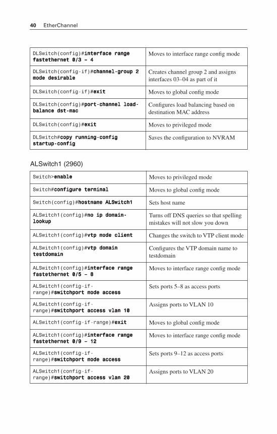
40 EtherChannel
ALSwitch1 (2960)
DLSwitch(config)#iiiinnnntttteeeerrrrffffaaaacccceeee rrrraaaannnnggggeeee ffffaaaasssstttteeeetttthhhheeeerrrrnnnneeeetttt 0000////3333 –––– 4444
Moves to interface range config mode
DLSwitch(config-if)#cccchhhhaaaannnnnnnneeeellll----ggggrrrroooouuuupppp 2222 mmmmooooddddeeee ddddeeeessssiiiirrrraaaabbbblllleeee
Creates channel group 2 and assigns interfaces 03–04 as part of it
DLSwitch(config-if)#eeeexxxxiiiitttt Moves to global config mode
DLSwitch(config)#ppppoooorrrrtttt----cccchhhhaaaannnnnnnneeeellll llllooooaaaadddd----bbbbaaaallllaaaannnncccceeee ddddsssstttt----mmmmaaaacccc
Configures load balancing based on destination MAC address
DLSwitch(config)#eeeexxxxiiiitttt Moves to privileged mode
DLSwitch#ccccooooppppyyyy rrrruuuunnnnnnnniiiinnnngggg----ccccoooonnnnffffiiiigggg ssssttttaaaarrrrttttuuuupppp----ccccoooonnnnffffiiiigggg
Saves the configuration to NVRAM
Switch>eeeennnnaaaabbbblllleeee Moves to privileged mode
Switch#ccccoooonnnnffffiiiigggguuuurrrreeee tttteeeerrrrmmmmiiiinnnnaaaallll Moves to global config mode
Switch(config)#hhhhoooossssttttnnnnaaaammmmeeee AAAALLLLSSSSwwwwiiiittttcccchhhh1111 Sets host name
ALSwitch1(config)#nnnnoooo iiiipppp ddddoooommmmaaaaiiiinnnn----llllooooooookkkkuuuupppp
Turns off DNS queries so that spelling mistakes will not slow you down
ALSwitch1(config)#vvvvttttpppp mmmmooooddddeeee cccclllliiiieeeennnntttt Changes the switch to VTP client mode
ALSwitch1(config)#vvvvttttpppp ddddoooommmmaaaaiiiinnnn tttteeeessssttttddddoooommmmaaaaiiiinnnn
Configures the VTP domain name to testdomain
ALSwitch1(config)#iiiinnnntttteeeerrrrffffaaaacccceeee rrrraaaannnnggggeeee ffffaaaasssstttteeeetttthhhheeeerrrrnnnneeeetttt 0000////5555 –––– 8888
Moves to interface range config mode
ALSwitch1(config-if-range)#sssswwwwiiiittttcccchhhhppppoooorrrrtttt mmmmooooddddeeee aaaacccccccceeeessssssss
Sets ports 5–8 as access ports
ALSwitch1(config-if-range)#sssswwwwiiiittttcccchhhhppppoooorrrrtttt aaaacccccccceeeessssssss vvvvllllaaaannnn 11110000
Assigns ports to VLAN 10
ALSwitch1(config-if-range)#eeeexxxxiiiitttt Moves to global config mode
ALSwitch1(config)#iiiinnnntttteeeerrrrffffaaaacccceeee rrrraaaannnnggggeeee ffffaaaasssstttteeeetttthhhheeeerrrrnnnneeeetttt 0000////9999 –––– 11112222
Moves to interface range config mode
ALSwitch1(config-if-range)#sssswwwwiiiittttcccchhhhppppoooorrrrtttt mmmmooooddddeeee aaaacccccccceeeessssssss
Sets ports 9–12 as access ports
ALSwitch1(config-if-range)#sssswwwwiiiittttcccchhhhppppoooorrrrtttt aaaacccccccceeeessssssss vvvvllllaaaannnn 22220000
Assigns ports to VLAN 20
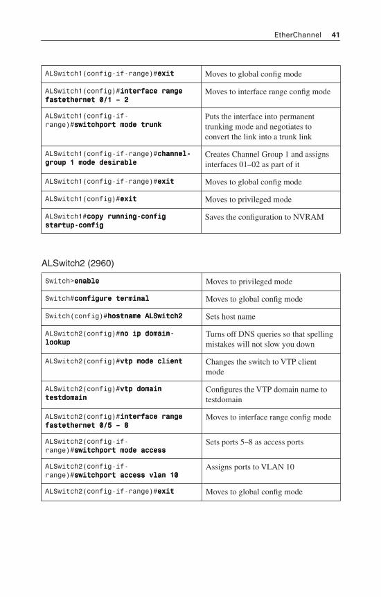
EtherChannel 41
ALSwitch2 (2960)
ALSwitch1(config-if-range)#eeeexxxxiiiitttt Moves to global config mode
ALSwitch1(config)#iiiinnnntttteeeerrrrffffaaaacccceeee rrrraaaannnnggggeeee ffffaaaasssstttteeeetttthhhheeeerrrrnnnneeeetttt 0000////1111 –––– 2222
Moves to interface range config mode
ALSwitch1(config-if-range)#sssswwwwiiiittttcccchhhhppppoooorrrrtttt mmmmooooddddeeee ttttrrrruuuunnnnkkkk
Puts the interface into permanent trunking mode and negotiates to convert the link into a trunk link
ALSwitch1(config-if-range)#cccchhhhaaaannnnnnnneeeellll----ggggrrrroooouuuupppp 1111 mmmmooooddddeeee ddddeeeessssiiiirrrraaaabbbblllleeee
Creates Channel Group 1 and assigns interfaces 01–02 as part of it
ALSwitch1(config-if-range)#eeeexxxxiiiitttt Moves to global config mode
ALSwitch1(config)#eeeexxxxiiiitttt Moves to privileged mode
ALSwitch1#ccccooooppppyyyy rrrruuuunnnnnnnniiiinnnngggg----ccccoooonnnnffffiiiigggg ssssttttaaaarrrrttttuuuupppp----ccccoooonnnnffffiiiigggg
Saves the configuration to NVRAM
Switch>eeeennnnaaaabbbblllleeee Moves to privileged mode
Switch#ccccoooonnnnffffiiiigggguuuurrrreeee tttteeeerrrrmmmmiiiinnnnaaaallll Moves to global config mode
Switch(config)#hhhhoooossssttttnnnnaaaammmmeeee AAAALLLLSSSSwwwwiiiittttcccchhhh2222 Sets host name
ALSwitch2(config)#nnnnoooo iiiipppp ddddoooommmmaaaaiiiinnnn----llllooooooookkkkuuuupppp
Turns off DNS queries so that spelling mistakes will not slow you down
ALSwitch2(config)#vvvvttttpppp mmmmooooddddeeee cccclllliiiieeeennnntttt Changes the switch to VTP client mode
ALSwitch2(config)#vvvvttttpppp ddddoooommmmaaaaiiiinnnn tttteeeessssttttddddoooommmmaaaaiiiinnnn
Configures the VTP domain name to testdomain
ALSwitch2(config)#iiiinnnntttteeeerrrrffffaaaacccceeee rrrraaaannnnggggeeee ffffaaaasssstttteeeetttthhhheeeerrrrnnnneeeetttt 0000////5555 –––– 8888
Moves to interface range config mode
ALSwitch2(config-if-range)#sssswwwwiiiittttcccchhhhppppoooorrrrtttt mmmmooooddddeeee aaaacccccccceeeessssssss
Sets ports 5–8 as access ports
ALSwitch2(config-if-range)#sssswwwwiiiittttcccchhhhppppoooorrrrtttt aaaacccccccceeeessssssss vvvvllllaaaannnn 11110000
Assigns ports to VLAN 10
ALSwitch2(config-if-range)#eeeexxxxiiiitttt Moves to global config mode
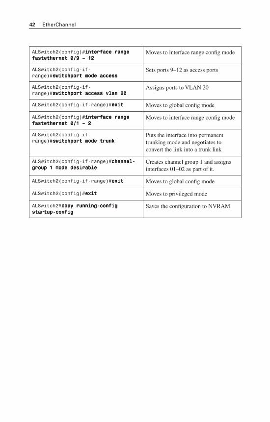
42 EtherChannel
ALSwitch2(config)#iiiinnnntttteeeerrrrffffaaaacccceeee rrrraaaannnnggggeeee ffffaaaasssstttteeeetttthhhheeeerrrrnnnneeeetttt 0000////9999 –––– 11112222
Moves to interface range config mode
ALSwitch2(config-if-range)#sssswwwwiiiittttcccchhhhppppoooorrrrtttt mmmmooooddddeeee aaaacccccccceeeessssssss
Sets ports 9–12 as access ports
ALSwitch2(config-if-range)#sssswwwwiiiittttcccchhhhppppoooorrrrtttt aaaacccccccceeeessssssss vvvvllllaaaannnn 22220000
Assigns ports to VLAN 20
ALSwitch2(config-if-range)#eeeexxxxiiiitttt Moves to global config mode
ALSwitch2(config)#iiiinnnntttteeeerrrrffffaaaacccceeee rrrraaaannnnggggeeee ffffaaaasssstttteeeetttthhhheeeerrrrnnnneeeetttt 0000////1111 –––– 2222
Moves to interface range config mode
ALSwitch2(config-if-range)#sssswwwwiiiittttcccchhhhppppoooorrrrtttt mmmmooooddddeeee ttttrrrruuuunnnnkkkk
Puts the interface into permanent trunking mode and negotiates to convert the link into a trunk link
ALSwitch2(config-if-range)#cccchhhhaaaannnnnnnneeeellll----ggggrrrroooouuuupppp 1111 mmmmooooddddeeee ddddeeeessssiiiirrrraaaabbbblllleeee
Creates channel group 1 and assigns interfaces 01–02 as part of it.
ALSwitch2(config-if-range)#eeeexxxxiiiitttt Moves to global config mode
ALSwitch2(config)#eeeexxxxiiiitttt Moves to privileged mode
ALSwitch2#ccccooooppppyyyy rrrruuuunnnnnnnniiiinnnngggg----ccccoooonnnnffffiiiigggg ssssttttaaaarrrrttttuuuupppp----ccccoooonnnnffffiiiigggg
Saves the configuration to NVRAM
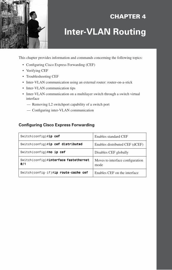
CHAPTER 4
Inter-VLAN Routing
This chapter provides information and commands concerning the following topics:
• Configuring Cisco Express Forwarding (CEF)
• Verifying CEF
• Troubleshooting CEF
• Inter-VLAN communication using an external router: router-on-a-stick
• Inter-VLAN communication tips
• Inter-VLAN communication on a multilayer switch through a switch virtual interface
— Removing L2 switchport capability of a switch port
— Configuring inter-VLAN communication
Configuring Cisco Express Forwarding
Switch(config)#iiiipppp cccceeeeffff Enables standard CEF
Switch(config)#iiiipppp cccceeeeffff ddddiiiissssttttrrrriiiibbbbuuuutttteeeedddd Enables distributed CEF (dCEF)
Switch(config)#nnnnoooo iiiipppp cccceeeeffff Disables CEF globally
Switch(config)#iiiinnnntttteeeerrrrffffaaaacccceeee ffffaaaasssstttteeeetttthhhheeeerrrrnnnneeeetttt 0000////1111
Moves to interface configuration mode
Switch(config-if)#iiiipppp rrrroooouuuutttteeee----ccccaaaacccchhhheeee cccceeeeffff Enables CEF on the interface
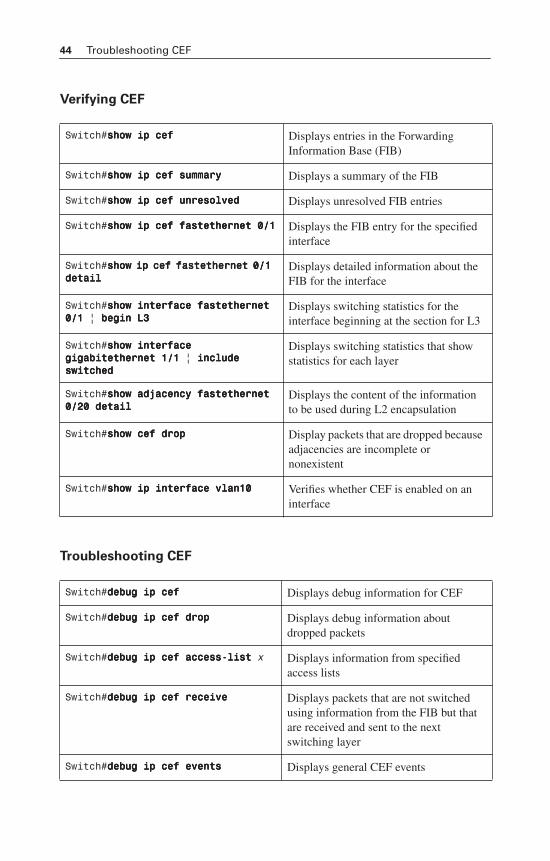
44 Troubleshooting CEF
Verifying CEF
Troubleshooting CEF
Switch#sssshhhhoooowwww iiiipppp cccceeeeffff Displays entries in the Forwarding Information Base (FIB)
Switch#sssshhhhoooowwww iiiipppp cccceeeeffff ssssuuuummmmmmmmaaaarrrryyyy Displays a summary of the FIB
Switch#sssshhhhoooowwww iiiipppp cccceeeeffff uuuunnnnrrrreeeessssoooollllvvvveeeedddd Displays unresolved FIB entries
Switch#sssshhhhoooowwww iiiipppp cccceeeeffff ffffaaaasssstttteeeetttthhhheeeerrrrnnnneeeetttt 0000////1111 Displays the FIB entry for the specified interface
Switch#sssshhhhoooowwww iiiipppp cccceeeeffff ffffaaaasssstttteeeetttthhhheeeerrrrnnnneeeetttt 0000////1111 ddddeeeettttaaaaiiiillll
Displays detailed information about the FIB for the interface
Switch#sssshhhhoooowwww iiiinnnntttteeeerrrrffffaaaacccceeee ffffaaaasssstttteeeetttthhhheeeerrrrnnnneeeetttt 0000////1111 | bbbbeeeeggggiiiinnnn LLLL3333
Displays switching statistics for the interface beginning at the section for L3
Switch#sssshhhhoooowwww iiiinnnntttteeeerrrrffffaaaacccceeee ggggiiiiggggaaaabbbbiiiitttteeeetttthhhheeeerrrrnnnneeeetttt 1111////1111 | iiiinnnncccclllluuuuddddeeee sssswwwwiiiittttcccchhhheeeedddd
Displays switching statistics that show statistics for each layer
Switch#sssshhhhoooowwww aaaaddddjjjjaaaacccceeeennnnccccyyyy ffffaaaasssstttteeeetttthhhheeeerrrrnnnneeeetttt 0000////22220000 ddddeeeettttaaaaiiiillll
Displays the content of the information to be used during L2 encapsulation
Switch#sssshhhhoooowwww cccceeeeffff ddddrrrroooopppp Display packets that are dropped because adjacencies are incomplete or nonexistent
Switch#sssshhhhoooowwww iiiipppp iiiinnnntttteeeerrrrffffaaaacccceeee vvvvllllaaaannnn11110000 Verifies whether CEF is enabled on an interface
Switch#ddddeeeebbbbuuuugggg iiiipppp cccceeeeffff Displays debug information for CEF
Switch#ddddeeeebbbbuuuugggg iiiipppp cccceeeeffff ddddrrrroooopppp Displays debug information about dropped packets
Switch#ddddeeeebbbbuuuugggg iiiipppp cccceeeeffff aaaacccccccceeeessssssss----lllliiiisssstttt x Displays information from specified access lists
Switch#ddddeeeebbbbuuuugggg iiiipppp cccceeeeffff rrrreeeecccceeeeiiiivvvveeee Displays packets that are not switched using information from the FIB but that are received and sent to the next switching layer
Switch#ddddeeeebbbbuuuugggg iiiipppp cccceeeeffff eeeevvvveeeennnnttttssss Displays general CEF events
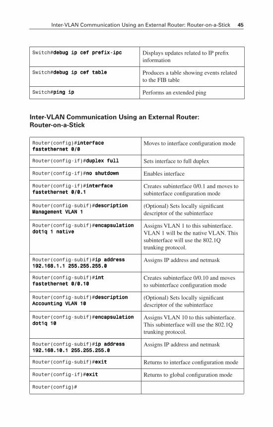
Inter-VLAN Communication Using an External Router: Router-on-a-Stick 45
Inter-VLAN Communication Using an External Router:
Router-on-a-Stick
Switch#ddddeeeebbbbuuuugggg iiiipppp cccceeeeffff pppprrrreeeeffffiiiixxxx----iiiippppcccc Displays updates related to IP prefix information
Switch#ddddeeeebbbbuuuugggg iiiipppp cccceeeeffff ttttaaaabbbblllleeee Produces a table showing events related to the FIB table
Switch#ppppiiiinnnngggg iiiipppp Performs an extended ping
Router(config)#iiiinnnntttteeeerrrrffffaaaacccceeee ffffaaaasssstttteeeetttthhhheeeerrrrnnnneeeetttt 0000////0000
Moves to interface configuration mode
Router(config-if)#dddduuuupppplllleeeexxxx ffffuuuullllllll Sets interface to full duplex
Router(config-if)#nnnnoooo sssshhhhuuuuttttddddoooowwwwnnnn Enables interface
Router(config-if)#iiiinnnntttteeeerrrrffffaaaacccceeee ffffaaaasssstttteeeetttthhhheeeerrrrnnnneeeetttt 0000////0000....1111
Creates subinterface 0/0.1 and moves to subinterface configuration mode
Router(config-subif)#ddddeeeessssccccrrrriiiippppttttiiiioooonnnn MMMMaaaannnnaaaaggggeeeemmmmeeeennnntttt VVVVLLLLAAAANNNN 1111
(Optional) Sets locally significant descriptor of the subinterface
Router(config-subif)#eeeennnnccccaaaappppssssuuuullllaaaattttiiiioooonnnn ddddooootttt1111qqqq 1111 nnnnaaaattttiiiivvvveeee
Assigns VLAN 1 to this subinterface. VLAN 1 will be the native VLAN. This subinterface will use the 802.1Q trunking protocol.
Router(config-subif)#iiiipppp aaaaddddddddrrrreeeessssssss 111199992222....111166668888....1111....1111 222255555555....222255555555....222255555555....0000
Assigns IP address and netmask
Router(config-subif)#iiiinnnntttt ffffaaaasssstttteeeetttthhhheeeerrrrnnnneeeetttt 0000////0000....11110000
Creates subinterface 0/0.10 and moves to subinterface configuration mode
Router(config-subif)#ddddeeeessssccccrrrriiiippppttttiiiioooonnnn AAAAccccccccoooouuuunnnnttttiiiinnnngggg VVVVLLLLAAAANNNN 11110000
(Optional) Sets locally significant descriptor of the subinterface
Router(config-subif)#eeeennnnccccaaaappppssssuuuullllaaaattttiiiioooonnnn ddddooootttt1111qqqq 11110000
Assigns VLAN 10 to this subinterface. This subinterface will use the 802.1Q trunking protocol.
Router(config-subif)#iiiipppp aaaaddddddddrrrreeeessssssss 111199992222....111166668888....11110000....1111 222255555555....222255555555....222255555555....0000
Assigns IP address and netmask
Router(config-subif)#eeeexxxxiiiitttt Returns to interface configuration mode
Router(config-if)#eeeexxxxiiiitttt Returns to global configuration mode
Router(config)#
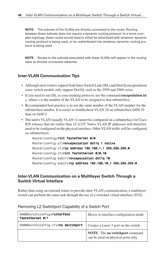
46 Inter-VLAN Communication on a Multilayer Switch Through a Switch Virtual…
NOTE: The subnets of the VLANs are directly connected to the router. Routing between these subnets does not require a dynamic routing protocol. In a more com-plex topology, these routes would need to either be advertised with whatever dynamic routing protocol is being used, or be redistributed into whatever dynamic routing pro-tocol is being used.
NOTE: Routes to the subnets associated with these VLANs will appear in the routing table as directly connected networks.
Inter-VLAN Communication Tips
• Although most routers support both Inter-Switch Link (ISL) and Dot1Q encapsulation some switch models only support Dot1Q, such as the 2950 and 2960 series.
• If you need to use ISL as your trunking protocol, use the command encapsulation isl x, where x is the number of the VLAN to be assigned to that subinterface.
• Recommended best practice is to use the same number of the VLAN number for the subinterface number. It is easier to troubleshoot VLAN 10 on subinterface fa0/0.10 than on fa0/0.2
• The native VLAN (usually VLAN 1) cannot be configured on a subinterface for Cisco IOS releases that are earlier than 12.1(3)T. Native VLAN IP addresses will therefore need to be configured on the physical interface. Other VLAN traffic will be configured on subinterfaces:
Router(config)#iiiinnnntttt ffffaaaasssstttteeeetttthhhheeeerrrrnnnneeeetttt 0000////0000
Router(config-if)#eeeennnnccccaaaappppssssuuuullllaaaattttiiiioooonnnn ddddooootttt1111qqqq 1111 nnnnaaaattttiiiivvvveeee
Router(config-if)#iiiipppp aaaaddddddddrrrreeeessssssss 111199992222....111166668888....1111....1111 222255555555....222255555555....222255555555....0000
Router(config-if)#iiiinnnntttt ffffaaaasssstttteeeetttthhhheeeerrrrnnnneeeetttt 0000////0000....11110000
Router(config-subif)#eeeennnnccccaaaappppssssuuuullllaaaattttiiiioooonnnn ddddooootttt1111qqqq 11110000
Router(config-subif)#iiiipppp aaaaddddddddrrrreeeessssssss 111199992222....111166668888....11110000....1111 222255555555....222255555555....222255555555....0000
Inter-VLAN Communication on a Multilayer Switch Through a
Switch Virtual Interface
Rather than using an external router to provide inter-VLAN communication, a multilayer switch can perform the same task through the use of a switched virtual interface (SVI).
Removing L2 Switchport Capability of a Switch Port
3560Switch(config)#iiiinnnntttteeeerrrrffffaaaacccceeee ffffaaaasssstttteeeetttthhhheeeerrrrnnnneeeetttt 0000////1111
Moves to interface configuration mode
3560Switch(config-if)#nnnnoooo sssswwwwiiiittttcccchhhhppppoooorrrrtttt Creates a Layer 3 port on the switch
NOTE: The no switchport commandcan be used on physical ports only.
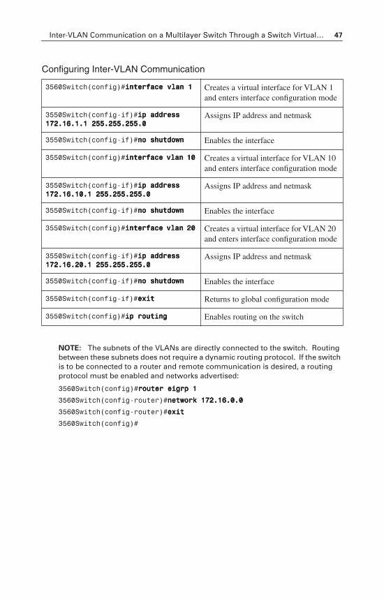
Inter-VLAN Communication on a Multilayer Switch Through a Switch Virtual… 47
Configuring Inter-VLAN Communication
NOTE: The subnets of the VLANs are directly connected to the switch. Routing between these subnets does not require a dynamic routing protocol. If the switch is to be connected to a router and remote communication is desired, a routing protocol must be enabled and networks advertised:
3560Switch(config)#rrrroooouuuutttteeeerrrr eeeeiiiiggggrrrrpppp 1111
3560Switch(config-router)#nnnneeeettttwwwwoooorrrrkkkk 111177772222....11116666....0000....0000
3560Switch(config-router)#eeeexxxxiiiitttt
3560Switch(config)#
3560Switch(config)#iiiinnnntttteeeerrrrffffaaaacccceeee vvvvllllaaaannnn 1111 Creates a virtual interface for VLAN 1 and enters interface configuration mode
3550Switch(config-if)#iiiipppp aaaaddddddddrrrreeeessssssss 111177772222....11116666....1111....1111 222255555555....222255555555....222255555555....0000
Assigns IP address and netmask
3550Switch(config-if)#nnnnoooo sssshhhhuuuuttttddddoooowwwwnnnn Enables the interface
3550Switch(config)#iiiinnnntttteeeerrrrffffaaaacccceeee vvvvllllaaaannnn 11110000 Creates a virtual interface for VLAN 10 and enters interface configuration mode
3550Switch(config-if)#iiiipppp aaaaddddddddrrrreeeessssssss 111177772222....11116666....11110000....1111 222255555555....222255555555....222255555555....0000
Assigns IP address and netmask
3550Switch(config-if)#nnnnoooo sssshhhhuuuuttttddddoooowwwwnnnn Enables the interface
3550Switch(config)#iiiinnnntttteeeerrrrffffaaaacccceeee vvvvllllaaaannnn 22220000 Creates a virtual interface for VLAN 20 and enters interface configuration mode
3550Switch(config-if)#iiiipppp aaaaddddddddrrrreeeessssssss 111177772222....11116666....22220000....1111 222255555555....222255555555....222255555555....0000
Assigns IP address and netmask
3550Switch(config-if)#nnnnoooo sssshhhhuuuuttttddddoooowwwwnnnn Enables the interface
3550Switch(config-if)#eeeexxxxiiiitttt Returns to global configuration mode
3550Switch(config)#iiiipppp rrrroooouuuuttttiiiinnnngggg Enables routing on the switch
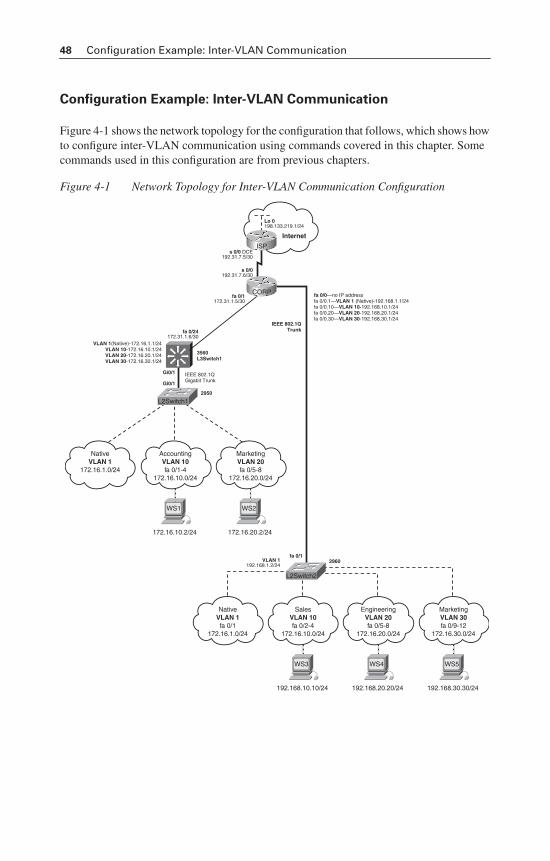
48 Configuration Example: Inter-VLAN Communication
Configuration Example: Inter-VLAN Communication
Figure 4-1 shows the network topology for the configuration that follows, which shows how to configure inter-VLAN communication using commands covered in this chapter. Some commands used in this configuration are from previous chapters.
Figure 4-1 Network Topology for Inter-VLAN Communication Configuration
192.168.30.30/24
WS5
Internet
IEEE 802.1QTrunk
3560L3Switch1
IEEE 802.1QGigabit Trunk
MarketingVLAN 30fa 0/9-12
172.16.30.0/24
192.168.20.20/24
WS4
EngineeringVLAN 20fa 0/5-8
172.16.20.0/24
192.168.10.10/24
WS3
SalesVLAN 10fa 0/2-4
172.16.10.0/24
NativeVLAN 1fa 0/1
172.16.1.0/24
172.16.20.2/24
WS2
MarketingVLAN 20fa 0/5-8
172.16.20.0/24
172.16.10.2/24
WS1
AccountingVLAN 10fa 0/1-4
172.16.10.0/24
NativeVLAN 1
172.16.1.0/24
CORP
ISP
Lo 0198.133.219.1/24
fa 0/0—no IP addressfa 0/0.1—VLAN 1 (Native)-192.168.1.1/24fa 0/0.10—VLAN 10-192.168.10.1/24fa 0/0.20—VLAN 20-192.168.20.1/24fa 0/0.30—VLAN 30-192.168.30.1/24
VLAN 1(Native)-172.16.1.1/24VLAN 10-172.16.10.1/24VLAN 20-172.16.20.1/24VLAN 30-172.16.30.1/24
fa 0/12960
2950
s 0/0 DCE192.31.7.5/30
s 0/0192.31.7.6/30
fa 0/1172.31.1.5/30
VLAN 1192.168.1.2/24
fa 0/24172.31.1.6/30
Gi0/1
Gi0/1
L2Switch2
L2Switch1
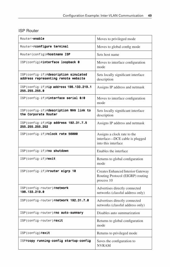
Configuration Example: Inter-VLAN Communication 49
ISP Router
Router>eeeennnnaaaabbbblllleeee Moves to privileged mode
Router>#ccccoooonnnnffffiiiigggguuuurrrreeee tttteeeerrrrmmmmiiiinnnnaaaallll Moves to global config mode
Router(config)#hhhhoooossssttttnnnnaaaammmmeeee IIIISSSSPPPP Sets host name
ISP(config)#iiiinnnntttteeeerrrrffffaaaacccceeee llllooooooooppppbbbbaaaacccckkkk 0000 Moves to interface configuration mode
ISP(config-if)#ddddeeeessssccccrrrriiiippppttttiiiioooonnnn ssssiiiimmmmuuuullllaaaatttteeeedddd aaaaddddddddrrrreeeessssssss rrrreeeepppprrrreeeesssseeeennnnttttiiiinnnngggg rrrreeeemmmmooootttteeee wwwweeeebbbbssssiiiitttteeee
Sets locally significant interface description
ISP(config-if)#iiiipppp aaaaddddddddrrrreeeessssssss 111199998888....111133333333....222211119999....1111 222255555555....222255555555....222255555555....0000
Assigns IP address and netmask
ISP(config-if)#iiiinnnntttteeeerrrrffffaaaacccceeee sssseeeerrrriiiiaaaallll 0000////0000 Moves to interface configuration mode
ISP(config-if)#ddddeeeessssccccrrrriiiippppttttiiiioooonnnn WWWWAAAANNNN lllliiiinnnnkkkk ttttoooo tttthhhheeee CCCCoooorrrrppppoooorrrraaaatttteeee RRRRoooouuuutttteeeerrrr
Sets locally significant interface description
ISP(config-if)#iiiipppp aaaaddddddddrrrreeeessssssss 111199992222....33331111....7777....5555 222255555555....222255555555....222255555555....222255552222
Assigns IP address and netmask
ISP(config-if)#cccclllloooocccckkkk rrrraaaatttteeee 55556666000000000000 Assigns a clock rate to the interface—DCE cable is plugged into this interface
ISP(config-if)#nnnnoooo sssshhhhuuuuttttddddoooowwwwnnnn Enables the interface
ISP(config-if)#eeeexxxxiiiitttt Returns to global configuration mode
ISP(config-if)#rrrroooouuuutttteeeerrrr eeeeiiiiggggrrrrpppp 11110000 Creates Enhanced Interior Gateway Routing Protocol (EIGRP) routing process 10
ISP(config-router)#nnnneeeettttwwwwoooorrrrkkkk 111199998888....111133333333....222211119999....0000
Advertises directly connected networks (classful address only)
ISP(config-router)#nnnneeeettttwwwwoooorrrrkkkk 111199992222....33331111....7777....0000 Advertises directly connected networks (classful address only)
ISP(config-router)#nnnnoooo aaaauuuuttttoooo----ssssuuuummmmmmmmaaaarrrryyyy Disables auto summarization
ISP(config-router)#eeeexxxxiiiitttt Returns to global configuration mode
ISP(config)#eeeexxxxiiiitttt Returns to privileged mode
ISP#ccccooooppppyyyy rrrruuuunnnnnnnniiiinnnngggg----ccccoooonnnnffffiiiigggg ssssttttaaaarrrrttttuuuupppp----ccccoooonnnnffffiiiigggg Saves the configuration to NVRAM
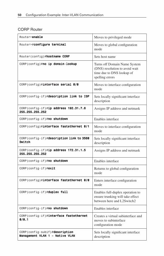
50 Configuration Example: Inter-VLAN Communication
CORP Router
Router>eeeennnnaaaabbbblllleeee Moves to privileged mode
Router>#ccccoooonnnnffffiiiigggguuuurrrreeee tttteeeerrrrmmmmiiiinnnnaaaallll Moves to global configuration mode
Router(config)#hhhhoooossssttttnnnnaaaammmmeeee CCCCOOOORRRRPPPP Sets host name
CORP(config)#nnnnoooo iiiipppp ddddoooommmmaaaaiiiinnnn----llllooooooookkkkuuuupppp Turns off Domain Name System (DNS) resolution to avoid wait time due to DNS lookup of spelling errors
CORP(config)#iiiinnnntttteeeerrrrffffaaaacccceeee sssseeeerrrriiiiaaaallll 0000////0000 Moves to interface configuration mode
CORP(config-if)#ddddeeeessssccccrrrriiiippppttttiiiioooonnnn lllliiiinnnnkkkk ttttoooo IIIISSSSPPPP Sets locally significant interface description
CORP(config-if)#iiiipppp aaaaddddddddrrrreeeessssssss 111199992222....33331111....7777....6666 222255555555....222255555555....222255555555....222255552222
Assigns IP address and netmask
CORP(config-if)#nnnnoooo sssshhhhuuuuttttddddoooowwwwnnnn Enables interface
CORP(config)#iiiinnnntttteeeerrrrffffaaaacccceeee ffffaaaasssstttteeeetttthhhheeeerrrrnnnneeeetttt 0000////1111 Moves to interface configuration mode
CORP(config-if)#ddddeeeessssccccrrrriiiippppttttiiiioooonnnn lllliiiinnnnkkkk ttttoooo 3333555566660000 SSSSwwwwiiiittttcccchhhh
Sets locally significant interface description
CORP(config-if)#iiiipppp aaaaddddddddrrrreeeessssssss 111177772222....33331111....1111....5555 222255555555....222255555555....222255555555....222255552222
Assigns IP address and netmask
CORP(config-if)#nnnnoooo sssshhhhuuuuttttddddoooowwwwnnnn Enables interface
CORP(config-if)#eeeexxxxiiiitttt Returns to global configuration mode
CORP(config)#iiiinnnntttteeeerrrrffffaaaacccceeee ffffaaaasssstttteeeetttthhhheeeerrrrnnnneeeetttt 0000////0000 Enters interface configuration mode
CORP(config-if)#dddduuuupppplllleeeexxxx ffffuuuullllllll Enables full-duplex operation to ensure trunking will take effect between here and L2Switch2
CORP(config-if)#nnnnoooo sssshhhhuuuuttttddddoooowwwwnnnn Enables interface
CORP(config-if)#iiiinnnntttteeeerrrrffffaaaacccceeee ffffaaaasssstttteeeetttthhhheeeerrrrnnnneeeetttt 0000////0000....1111
Creates a virtual subinterface and moves to subinterface configuration mode
CORP(config-subif)#ddddeeeessssccccrrrriiiippppttttiiiioooonnnn MMMMaaaannnnaaaaggggeeeemmmmeeeennnntttt VVVVLLLLAAAANNNN 1111 –––– NNNNaaaattttiiiivvvveeee VVVVLLLLAAAANNNN
Sets locally significant interface description
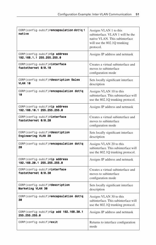
Configuration Example: Inter-VLAN Communication 51
CORP(config-subif)#eeeennnnccccaaaappppssssuuuullllaaaattttiiiioooonnnn ddddooootttt1111qqqq 1111 nnnnaaaattttiiiivvvveeee
Assigns VLAN 1 to this subinterface. VLAN 1 will be the native VLAN. This subinterface will use the 802.1Q trunking protocol.
CORP(config-subif)#iiiipppp aaaaddddddddrrrreeeessssssss 111199992222....111166668888....1111....1111 222255555555....222255555555....222255555555....0000
Assigns IP address and netmask
CORP(config-subif)#iiiinnnntttteeeerrrrffffaaaacccceeee ffffaaaasssstttteeeetttthhhheeeerrrrnnnneeeetttt 0000////0000....11110000
Creates a virtual subinterface and moves to subinterface configuration mode
CORP(config-subif)#ddddeeeessssccccrrrriiiippppttttiiiioooonnnn SSSSaaaalllleeeessss VVVVLLLLAAAANNNN 11110000
Sets locally significant interface description
CORP(config-subif)#eeeennnnccccaaaappppssssuuuullllaaaattttiiiioooonnnn ddddooootttt1111qqqq 11110000
Assigns VLAN 10 to this subinterface. This subinterface will use the 802.1Q trunking protocol.
CORP(config-subif)#iiiipppp aaaaddddddddrrrreeeessssssss 111199992222....111166668888....11110000....1111 222255555555....222255555555....222255555555....0000
Assigns IP address and netmask
CORP(config-subif)#iiiinnnntttteeeerrrrffffaaaacccceeee ffffaaaasssstttteeeetttthhhheeeerrrrnnnneeeetttt 0000////0000....22220000
Creates a virtual subinterface and moves to subinterface configuration mode
CORP(config-subif)#ddddeeeessssccccrrrriiiippppttttiiiioooonnnn EEEEnnnnggggiiiinnnneeeeeeeerrrriiiinnnngggg VVVVLLLLAAAANNNN 22220000
Sets locally significant interface description
CORP(config-subif)#eeeennnnccccaaaappppssssuuuullllaaaattttiiiioooonnnn ddddooootttt1111qqqq 22220000
Assigns VLAN 20 to this subinterface. This subinterface will use the 802.1Q trunking protocol.
CORP(config-subif)#iiiipppp aaaaddddddddrrrreeeessssssss 111199992222....111166668888....22220000....1111 222255555555....222255555555....222255555555....0000
Assigns IP address and netmask
CORP(config-subif)#iiiinnnntttteeeerrrrffffaaaacccceeee ffffaaaasssstttteeeetttthhhheeeerrrrnnnneeeetttt 0000////0000....33330000
Creates a virtual subinterface and moves to subinterface configuration mode
CORP(config-subif)#ddddeeeessssccccrrrriiiippppttttiiiioooonnnn MMMMaaaarrrrkkkkeeeettttiiiinnnngggg VVVVLLLLAAAANNNN 33330000
Sets locally significant interface description
CORP(config-subif)#eeeennnnccccaaaappppssssuuuullllaaaattttiiiioooonnnn ddddooootttt1111qqqq 33330000
Assigns VLAN 30 to this subinterface. This subinterface will use the 802.1Q trunking protocol.
CORP(config-subif)#iiiipppp aaaadddddddd 111199992222....111166668888....33330000....1111 222255555555....222255555555....222255555555....0000
Assigns IP address and netmask
CORP(config-subif)#eeeexxxxiiiitttt Returns to interface configuration mode
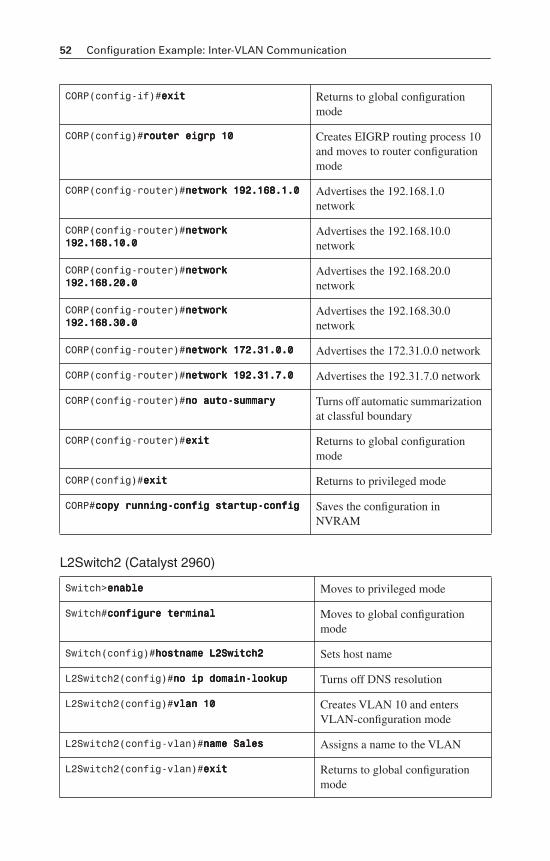
52 Configuration Example: Inter-VLAN Communication
L2Switch2 (Catalyst 2960)
CORP(config-if)#eeeexxxxiiiitttt Returns to global configuration mode
CORP(config)#rrrroooouuuutttteeeerrrr eeeeiiiiggggrrrrpppp 11110000 Creates EIGRP routing process 10 and moves to router configuration mode
CORP(config-router)#nnnneeeettttwwwwoooorrrrkkkk 111199992222....111166668888....1111....0000 Advertises the 192.168.1.0 network
CORP(config-router)#nnnneeeettttwwwwoooorrrrkkkk 111199992222....111166668888....11110000....0000
Advertises the 192.168.10.0 network
CORP(config-router)#nnnneeeettttwwwwoooorrrrkkkk 111199992222....111166668888....22220000....0000
Advertises the 192.168.20.0 network
CORP(config-router)#nnnneeeettttwwwwoooorrrrkkkk 111199992222....111166668888....33330000....0000
Advertises the 192.168.30.0 network
CORP(config-router)#nnnneeeettttwwwwoooorrrrkkkk 111177772222....33331111....0000....0000 Advertises the 172.31.0.0 network
CORP(config-router)#nnnneeeettttwwwwoooorrrrkkkk 111199992222....33331111....7777....0000 Advertises the 192.31.7.0 network
CORP(config-router)#nnnnoooo aaaauuuuttttoooo----ssssuuuummmmmmmmaaaarrrryyyy Turns off automatic summarization at classful boundary
CORP(config-router)#eeeexxxxiiiitttt Returns to global configuration mode
CORP(config)#eeeexxxxiiiitttt Returns to privileged mode
CORP#ccccooooppppyyyy rrrruuuunnnnnnnniiiinnnngggg----ccccoooonnnnffffiiiigggg ssssttttaaaarrrrttttuuuupppp----ccccoooonnnnffffiiiigggg Saves the configuration in NVRAM
Switch>eeeennnnaaaabbbblllleeee Moves to privileged mode
Switch#ccccoooonnnnffffiiiigggguuuurrrreeee tttteeeerrrrmmmmiiiinnnnaaaallll Moves to global configuration mode
Switch(config)#hhhhoooossssttttnnnnaaaammmmeeee LLLL2222SSSSwwwwiiiittttcccchhhh2222 Sets host name
L2Switch2(config)#nnnnoooo iiiipppp ddddoooommmmaaaaiiiinnnn----llllooooooookkkkuuuupppp Turns off DNS resolution
L2Switch2(config)#vvvvllllaaaannnn 11110000 Creates VLAN 10 and enters VLAN-configuration mode
L2Switch2(config-vlan)#nnnnaaaammmmeeee SSSSaaaalllleeeessss Assigns a name to the VLAN
L2Switch2(config-vlan)#eeeexxxxiiiitttt Returns to global configuration mode
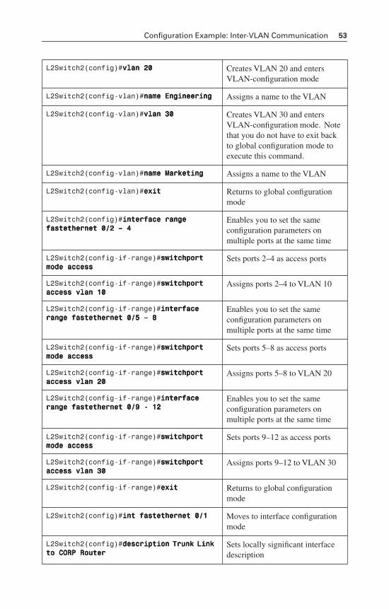
Configuration Example: Inter-VLAN Communication 53
L2Switch2(config)#vvvvllllaaaannnn 22220000 Creates VLAN 20 and enters VLAN-configuration mode
L2Switch2(config-vlan)#nnnnaaaammmmeeee EEEEnnnnggggiiiinnnneeeeeeeerrrriiiinnnngggg Assigns a name to the VLAN
L2Switch2(config-vlan)#vvvvllllaaaannnn 33330000 Creates VLAN 30 and enters VLAN-configuration mode. Note that you do not have to exit back to global configuration mode to execute this command.
L2Switch2(config-vlan)#nnnnaaaammmmeeee MMMMaaaarrrrkkkkeeeettttiiiinnnngggg Assigns a name to the VLAN
L2Switch2(config-vlan)#eeeexxxxiiiitttt Returns to global configuration mode
L2Switch2(config)#iiiinnnntttteeeerrrrffffaaaacccceeee rrrraaaannnnggggeeee ffffaaaasssstttteeeetttthhhheeeerrrrnnnneeeetttt 0000////2222 –––– 4444
Enables you to set the same configuration parameters on multiple ports at the same time
L2Switch2(config-if-range)#sssswwwwiiiittttcccchhhhppppoooorrrrtttt mmmmooooddddeeee aaaacccccccceeeessssssss
Sets ports 2–4 as access ports
L2Switch2(config-if-range)#sssswwwwiiiittttcccchhhhppppoooorrrrtttt aaaacccccccceeeessssssss vvvvllllaaaannnn 11110000
Assigns ports 2–4 to VLAN 10
L2Switch2(config-if-range)#iiiinnnntttteeeerrrrffffaaaacccceeee rrrraaaannnnggggeeee ffffaaaasssstttteeeetttthhhheeeerrrrnnnneeeetttt 0000////5555 –––– 8888
Enables you to set the same configuration parameters on multiple ports at the same time
L2Switch2(config-if-range)#sssswwwwiiiittttcccchhhhppppoooorrrrtttt mmmmooooddddeeee aaaacccccccceeeessssssss
Sets ports 5–8 as access ports
L2Switch2(config-if-range)#sssswwwwiiiittttcccchhhhppppoooorrrrtttt aaaacccccccceeeessssssss vvvvllllaaaannnn 22220000
Assigns ports 5–8 to VLAN 20
L2Switch2(config-if-range)#iiiinnnntttteeeerrrrffffaaaacccceeee rrrraaaannnnggggeeee ffffaaaasssstttteeeetttthhhheeeerrrrnnnneeeetttt 0000////9999 ---- 11112222
Enables you to set the same configuration parameters on multiple ports at the same time
L2Switch2(config-if-range)#sssswwwwiiiittttcccchhhhppppoooorrrrtttt mmmmooooddddeeee aaaacccccccceeeessssssss
Sets ports 9–12 as access ports
L2Switch2(config-if-range)#sssswwwwiiiittttcccchhhhppppoooorrrrtttt aaaacccccccceeeessssssss vvvvllllaaaannnn 33330000
Assigns ports 9–12 to VLAN 30
L2Switch2(config-if-range)#eeeexxxxiiiitttt Returns to global configuration mode
L2Switch2(config)#iiiinnnntttt ffffaaaasssstttteeeetttthhhheeeerrrrnnnneeeetttt 0000////1111 Moves to interface configuration mode
L2Switch2(config)#ddddeeeessssccccrrrriiiippppttttiiiioooonnnn TTTTrrrruuuunnnnkkkk LLLLiiiinnnnkkkk ttttoooo CCCCOOOORRRRPPPP RRRRoooouuuutttteeeerrrr
Sets locally significant interface description
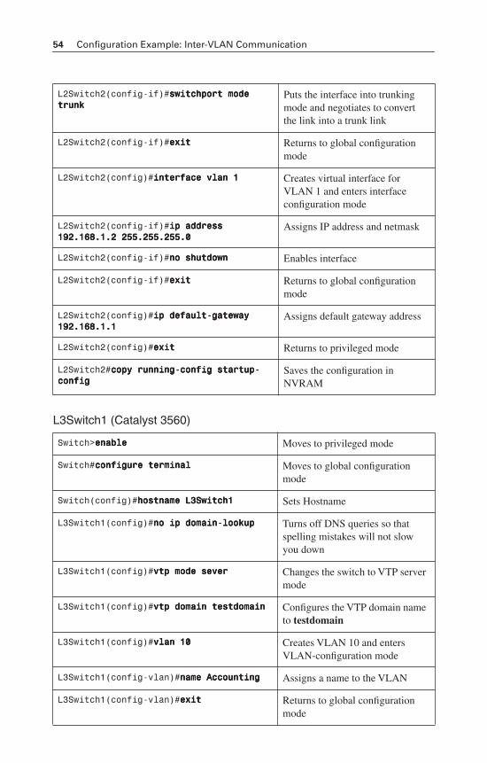
54 Configuration Example: Inter-VLAN Communication
L3Switch1 (Catalyst 3560)
L2Switch2(config-if)#sssswwwwiiiittttcccchhhhppppoooorrrrtttt mmmmooooddddeeee ttttrrrruuuunnnnkkkk
Puts the interface into trunking mode and negotiates to convert the link into a trunk link
L2Switch2(config-if)#eeeexxxxiiiitttt Returns to global configuration mode
L2Switch2(config)#iiiinnnntttteeeerrrrffffaaaacccceeee vvvvllllaaaannnn 1111 Creates virtual interface for VLAN 1 and enters interface configuration mode
L2Switch2(config-if)#iiiipppp aaaaddddddddrrrreeeessssssss 111199992222....111166668888....1111....2222 222255555555....222255555555....222255555555....0000
Assigns IP address and netmask
L2Switch2(config-if)#nnnnoooo sssshhhhuuuuttttddddoooowwwwnnnn Enables interface
L2Switch2(config-if)#eeeexxxxiiiitttt Returns to global configuration mode
L2Switch2(config)#iiiipppp ddddeeeeffffaaaauuuulllltttt----ggggaaaatttteeeewwwwaaaayyyy 111199992222....111166668888....1111....1111
Assigns default gateway address
L2Switch2(config)#eeeexxxxiiiitttt Returns to privileged mode
L2Switch2#ccccooooppppyyyy rrrruuuunnnnnnnniiiinnnngggg----ccccoooonnnnffffiiiigggg ssssttttaaaarrrrttttuuuupppp----ccccoooonnnnffffiiiigggg
Saves the configuration in NVRAM
Switch>eeeennnnaaaabbbblllleeee Moves to privileged mode
Switch#ccccoooonnnnffffiiiigggguuuurrrreeee tttteeeerrrrmmmmiiiinnnnaaaallll Moves to global configuration mode
Switch(config)#hhhhoooossssttttnnnnaaaammmmeeee LLLL3333SSSSwwwwiiiittttcccchhhh1111 Sets Hostname
L3Switch1(config)#nnnnoooo iiiipppp ddddoooommmmaaaaiiiinnnn----llllooooooookkkkuuuupppp Turns off DNS queries so that spelling mistakes will not slow you down
L3Switch1(config)#vvvvttttpppp mmmmooooddddeeee sssseeeevvvveeeerrrr Changes the switch to VTP server mode
L3Switch1(config)#vvvvttttpppp ddddoooommmmaaaaiiiinnnn tttteeeessssttttddddoooommmmaaaaiiiinnnn Configures the VTP domain name to testdomain
L3Switch1(config)#vvvvllllaaaannnn 11110000 Creates VLAN 10 and enters VLAN-configuration mode
L3Switch1(config-vlan)#nnnnaaaammmmeeee AAAAccccccccoooouuuunnnnttttiiiinnnngggg Assigns a name to the VLAN
L3Switch1(config-vlan)#eeeexxxxiiiitttt Returns to global configuration mode
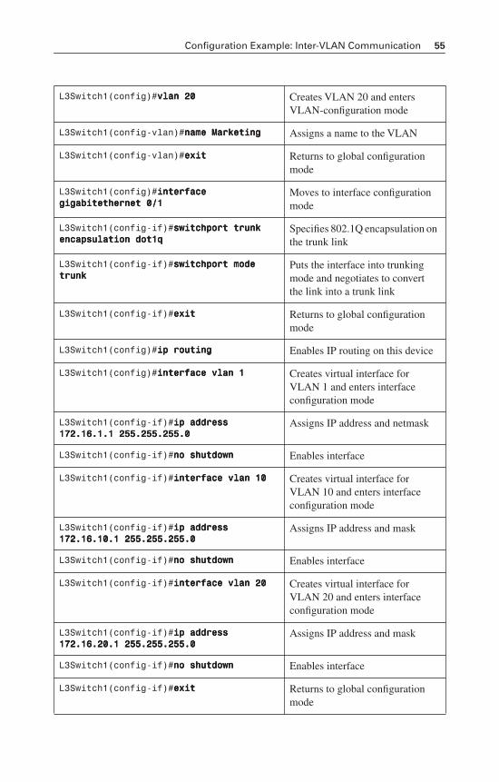
Configuration Example: Inter-VLAN Communication 55
L3Switch1(config)#vvvvllllaaaannnn 22220000 Creates VLAN 20 and enters VLAN-configuration mode
L3Switch1(config-vlan)#nnnnaaaammmmeeee MMMMaaaarrrrkkkkeeeettttiiiinnnngggg Assigns a name to the VLAN
L3Switch1(config-vlan)#eeeexxxxiiiitttt Returns to global configuration mode
L3Switch1(config)#iiiinnnntttteeeerrrrffffaaaacccceeee ggggiiiiggggaaaabbbbiiiitttteeeetttthhhheeeerrrrnnnneeeetttt 0000////1111
Moves to interface configuration mode
L3Switch1(config-if)#sssswwwwiiiittttcccchhhhppppoooorrrrtttt ttttrrrruuuunnnnkkkk eeeennnnccccaaaappppssssuuuullllaaaattttiiiioooonnnn ddddooootttt1111qqqq
Specifies 802.1Q encapsulation on the trunk link
L3Switch1(config-if)#sssswwwwiiiittttcccchhhhppppoooorrrrtttt mmmmooooddddeeee ttttrrrruuuunnnnkkkk
Puts the interface into trunking mode and negotiates to convert the link into a trunk link
L3Switch1(config-if)#eeeexxxxiiiitttt Returns to global configuration mode
L3Switch1(config)#iiiipppp rrrroooouuuuttttiiiinnnngggg Enables IP routing on this device
L3Switch1(config)#iiiinnnntttteeeerrrrffffaaaacccceeee vvvvllllaaaannnn 1111 Creates virtual interface for VLAN 1 and enters interface configuration mode
L3Switch1(config-if)#iiiipppp aaaaddddddddrrrreeeessssssss 111177772222....11116666....1111....1111 222255555555....222255555555....222255555555....0000
Assigns IP address and netmask
L3Switch1(config-if)#nnnnoooo sssshhhhuuuuttttddddoooowwwwnnnn Enables interface
L3Switch1(config-if)#iiiinnnntttteeeerrrrffffaaaacccceeee vvvvllllaaaannnn 11110000 Creates virtual interface for VLAN 10 and enters interface configuration mode
L3Switch1(config-if)#iiiipppp aaaaddddddddrrrreeeessssssss 111177772222....11116666....11110000....1111 222255555555....222255555555....222255555555....0000
Assigns IP address and mask
L3Switch1(config-if)#nnnnoooo sssshhhhuuuuttttddddoooowwwwnnnn Enables interface
L3Switch1(config-if)#iiiinnnntttteeeerrrrffffaaaacccceeee vvvvllllaaaannnn 22220000 Creates virtual interface for VLAN 20 and enters interface configuration mode
L3Switch1(config-if)#iiiipppp aaaaddddddddrrrreeeessssssss 111177772222....11116666....22220000....1111 222255555555....222255555555....222255555555....0000
Assigns IP address and mask
L3Switch1(config-if)#nnnnoooo sssshhhhuuuuttttddddoooowwwwnnnn Enables interface
L3Switch1(config-if)#eeeexxxxiiiitttt Returns to global configuration mode
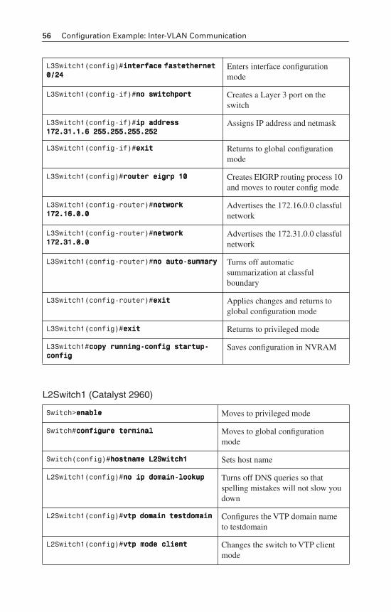
56 Configuration Example: Inter-VLAN Communication
L2Switch1 (Catalyst 2960)
L3Switch1(config)#iiiinnnntttteeeerrrrffffaaaacccceeee ffffaaaasssstttteeeetttthhhheeeerrrrnnnneeeetttt 0000////22224444
Enters interface configuration mode
L3Switch1(config-if)#nnnnoooo sssswwwwiiiittttcccchhhhppppoooorrrrtttt Creates a Layer 3 port on the switch
L3Switch1(config-if)#iiiipppp aaaaddddddddrrrreeeessssssss 111177772222....33331111....1111....6666 222255555555....222255555555....222255555555....222255552222
Assigns IP address and netmask
L3Switch1(config-if)#eeeexxxxiiiitttt Returns to global configuration mode
L3Switch1(config)#rrrroooouuuutttteeeerrrr eeeeiiiiggggrrrrpppp 11110000 Creates EIGRP routing process 10 and moves to router config mode
L3Switch1(config-router)#nnnneeeettttwwwwoooorrrrkkkk 111177772222....11116666....0000....0000
Advertises the 172.16.0.0 classful network
L3Switch1(config-router)#nnnneeeettttwwwwoooorrrrkkkk 111177772222....33331111....0000....0000
Advertises the 172.31.0.0 classful network
L3Switch1(config-router)#nnnnoooo aaaauuuuttttoooo----ssssuuuummmmmmmmaaaarrrryyyy Turns off automatic summarization at classful boundary
L3Switch1(config-router)#eeeexxxxiiiitttt Applies changes and returns to global configuration mode
L3Switch1(config)#eeeexxxxiiiitttt Returns to privileged mode
L3Switch1#ccccooooppppyyyy rrrruuuunnnnnnnniiiinnnngggg----ccccoooonnnnffffiiiigggg ssssttttaaaarrrrttttuuuupppp----ccccoooonnnnffffiiiigggg
Saves configuration in NVRAM
Switch>eeeennnnaaaabbbblllleeee Moves to privileged mode
Switch#ccccoooonnnnffffiiiigggguuuurrrreeee tttteeeerrrrmmmmiiiinnnnaaaallll Moves to global configuration mode
Switch(config)#hhhhoooossssttttnnnnaaaammmmeeee LLLL2222SSSSwwwwiiiittttcccchhhh1111 Sets host name
L2Switch1(config)#nnnnoooo iiiipppp ddddoooommmmaaaaiiiinnnn----llllooooooookkkkuuuupppp Turns off DNS queries so that spelling mistakes will not slow you down
L2Switch1(config)#vvvvttttpppp ddddoooommmmaaaaiiiinnnn tttteeeessssttttddddoooommmmaaaaiiiinnnn Configures the VTP domain name to testdomain
L2Switch1(config)#vvvvttttpppp mmmmooooddddeeee cccclllliiiieeeennnntttt Changes the switch to VTP client mode
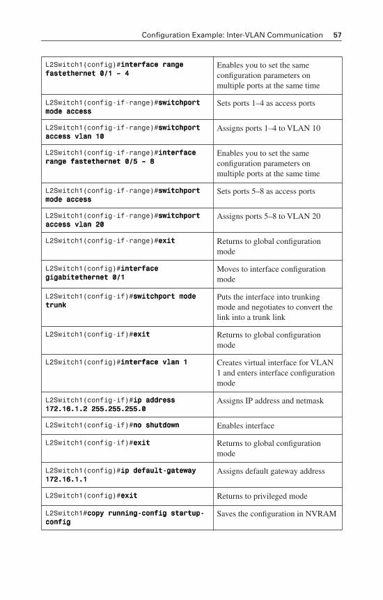
Configuration Example: Inter-VLAN Communication 57
L2Switch1(config)#iiiinnnntttteeeerrrrffffaaaacccceeee rrrraaaannnnggggeeee ffffaaaasssstttteeeetttthhhheeeerrrrnnnneeeetttt 0000////1111 –––– 4444
Enables you to set the same configuration parameters on multiple ports at the same time
L2Switch1(config-if-range)#sssswwwwiiiittttcccchhhhppppoooorrrrtttt mmmmooooddddeeee aaaacccccccceeeessssssss
Sets ports 1–4 as access ports
L2Switch1(config-if-range)#sssswwwwiiiittttcccchhhhppppoooorrrrtttt aaaacccccccceeeessssssss vvvvllllaaaannnn 11110000
Assigns ports 1–4 to VLAN 10
L2Switch1(config-if-range)#iiiinnnntttteeeerrrrffffaaaacccceeee rrrraaaannnnggggeeee ffffaaaasssstttteeeetttthhhheeeerrrrnnnneeeetttt 0000////5555 –––– 8888
Enables you to set the same configuration parameters on multiple ports at the same time
L2Switch1(config-if-range)#sssswwwwiiiittttcccchhhhppppoooorrrrtttt mmmmooooddddeeee aaaacccccccceeeessssssss
Sets ports 5–8 as access ports
L2Switch1(config-if-range)#sssswwwwiiiittttcccchhhhppppoooorrrrtttt aaaacccccccceeeessssssss vvvvllllaaaannnn 22220000
Assigns ports 5–8 to VLAN 20
L2Switch1(config-if-range)#eeeexxxxiiiitttt Returns to global configuration mode
L2Switch1(config)#iiiinnnntttteeeerrrrffffaaaacccceeee ggggiiiiggggaaaabbbbiiiitttteeeetttthhhheeeerrrrnnnneeeetttt 0000////1111
Moves to interface configuration mode
L2Switch1(config-if)#sssswwwwiiiittttcccchhhhppppoooorrrrtttt mmmmooooddddeeee ttttrrrruuuunnnnkkkk
Puts the interface into trunking mode and negotiates to convert the link into a trunk link
L2Switch1(config-if)#eeeexxxxiiiitttt Returns to global configuration mode
L2Switch1(config)#iiiinnnntttteeeerrrrffffaaaacccceeee vvvvllllaaaannnn 1111 Creates virtual interface for VLAN 1 and enters interface configuration mode
L2Switch1(config-if)#iiiipppp aaaaddddddddrrrreeeessssssss 111177772222....11116666....1111....2222 222255555555....222255555555....222255555555....0000
Assigns IP address and netmask
L2Switch1(config-if)#nnnnoooo sssshhhhuuuuttttddddoooowwwwnnnn Enables interface
L2Switch1(config-if)#eeeexxxxiiiitttt Returns to global configuration mode
L2Switch1(config)#iiiipppp ddddeeeeffffaaaauuuulllltttt----ggggaaaatttteeeewwwwaaaayyyy 111177772222....11116666....1111....1111
Assigns default gateway address
L2Switch1(config)#eeeexxxxiiiitttt Returns to privileged mode
L2Switch1#ccccooooppppyyyy rrrruuuunnnnnnnniiiinnnngggg----ccccoooonnnnffffiiiigggg ssssttttaaaarrrrttttuuuupppp----ccccoooonnnnffffiiiigggg
Saves the configuration in NVRAM

This page intentionally left blank
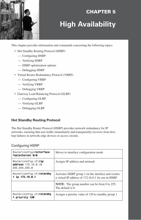
CHAPTER 5
High Availability
This chapter provides information and commands concerning the following topics:
• Hot Standby Routing Protocol (HSRP)
— Configuring HSRP
— Verifying HSRP
— HSRP optimization options
— Debugging HSRP
• Virtual Router Redundancy Protocol (VRRP)
— Configuring VRRP
— Verifying VRRP
— Debugging VRRP
• Gateway Load Balancing Protocol (GLBP)
— Configuring GLBP
— Verifying GLBP
— Debugging GLBP
Hot Standby Routing Protocol
The Hot Standby Router Protocol (HSRP) provides network redundancy for IP networks, ensuring that user traffic immediately and transparently recovers from first-hop failures in network edge devices or access circuits.
Configuring HSRP
Router(config)#iiiinnnntttteeeerrrrffffaaaacccceeee ffffaaaasssstttteeeetttthhhheeeerrrrnnnneeeetttt 0000////0000
Moves to interface configuration mode
Router(config-if)#iiiipppp aaaaddddddddrrrreeeessssssss 172.16.0.10 255.255.255.0
Assigns IP address and netmask
Router(config-if)#ssssttttaaaannnnddddbbbbyyyy 1111 iiiipppp 111177772222....11116666....0000....1111
Activates HSRP group 1 on the interface and creates a virtual IP address of 172.16.0.1 for use in HSRP
NOTE: The group number can be from 0 to 255. The default is 0.
Router(config-if)#ssssttttaaaannnnddddbbbbyyyy 1111 pppprrrriiiioooorrrriiiittttyyyy 111122220000
Assigns a priority value of 120 to standby group 1
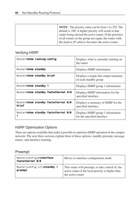
60 Hot Standby Routing Protocol
Verifying HSRP
HSRP Optimization OptionsThere are options available that make it possible to optimize HSRP operation in the campus network. The next three sections explain three of these options: standby preempt, message timers, and interface tracking.
Preempt
NOTE: The priority value can be from 1 to 255. The default is 100. A higher priority will result in that router being elected the active router. If the priorities of all routers in the group are equal, the router with the highest IP address becomes the active router.
Router#sssshhhhoooowwww rrrruuuunnnnnnnniiiinnnngggg----ccccoooonnnnffffiiiigggg Displays what is currently running on the router
Router#sssshhhhoooowwww ssssttttaaaannnnddddbbbbyyyy Displays HSRP information
Router#sssshhhhoooowwww ssssttttaaaannnnddddbbbbyyyy bbbbrrrriiiieeeeffff Displays a single-line output summary of each standby group
Router#sssshhhhoooowwww ssssttttaaaannnnddddbbbbyyyy 1111 Displays HSRP group 1 information
Router#sssshhhhoooowwww ssssttttaaaannnnddddbbbbyyyy ffffaaaasssstttteeeetttthhhheeeerrrrnnnneeeetttt 0000////0000 Displays HSRP information for the specified interface
Router#sssshhhhoooowwww ssssttttaaaannnnddddbbbbyyyy ffffaaaasssstttteeeetttthhhheeeerrrrnnnneeeetttt 0000////0000 bbbbrrrriiiieeeeffff
Displays a summary of HSRP for the specified interface
Router#sssshhhhoooowwww ssssttttaaaannnnddddbbbbyyyy ffffaaaasssstttteeeetttthhhheeeerrrrnnnneeeetttt 0000////0000 1111
Displays HSRP group 1 information for the specified interface
Router(config)#iiiinnnntttteeeerrrrffffaaaacccceeee ffffaaaasssstttteeeetttthhhheeeerrrrnnnneeeetttt 0000////0000
Moves to interface configuration mode
Router(config-if)#ssssttttaaaannnnddddbbbbyyyy 1111 pppprrrreeeeeeeemmmmpppptttt
This router will preempt, or take control of, the active router if the local priority is higher than the active router
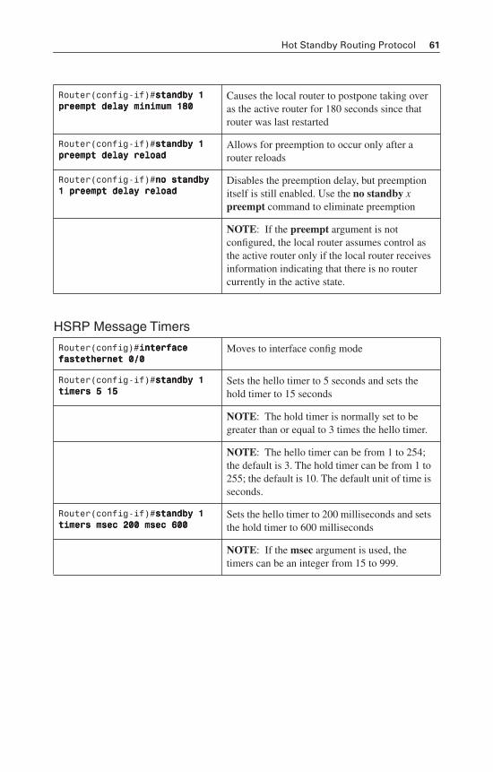
Hot Standby Routing Protocol 61
HSRP Message Timers
Router(config-if)#ssssttttaaaannnnddddbbbbyyyy 1111 pppprrrreeeeeeeemmmmpppptttt ddddeeeellllaaaayyyy mmmmiiiinnnniiiimmmmuuuummmm 111188880000
Causes the local router to postpone taking over as the active router for 180 seconds since that router was last restarted
Router(config-if)#ssssttttaaaannnnddddbbbbyyyy 1111 pppprrrreeeeeeeemmmmpppptttt ddddeeeellllaaaayyyy rrrreeeellllooooaaaadddd
Allows for preemption to occur only after a router reloads
Router(config-if)#nnnnoooo ssssttttaaaannnnddddbbbbyyyy 1111 pppprrrreeeeeeeemmmmpppptttt ddddeeeellllaaaayyyy rrrreeeellllooooaaaadddd
Disables the preemption delay, but preemption itself is still enabled. Use the no standby xpreempt command to eliminate preemption
NOTE: If the preempt argument is not configured, the local router assumes control as the active router only if the local router receives information indicating that there is no router currently in the active state.
Router(config)#iiiinnnntttteeeerrrrffffaaaacccceeee ffffaaaasssstttteeeetttthhhheeeerrrrnnnneeeetttt 0000////0000
Moves to interface config mode
Router(config-if)#ssssttttaaaannnnddddbbbbyyyy 1111 ttttiiiimmmmeeeerrrrssss 5555 11115555
Sets the hello timer to 5 seconds and sets the hold timer to 15 seconds
NOTE: The hold timer is normally set to be greater than or equal to 3 times the hello timer.
NOTE: The hello timer can be from 1 to 254; the default is 3. The hold timer can be from 1 to 255; the default is 10. The default unit of time is seconds.
Router(config-if)#ssssttttaaaannnnddddbbbbyyyy 1111 ttttiiiimmmmeeeerrrrssss mmmmsssseeeecccc 222200000000 mmmmsssseeeecccc 666600000000
Sets the hello timer to 200 milliseconds and sets the hold timer to 600 milliseconds
NOTE: If the msec argument is used, the timers can be an integer from 15 to 999.
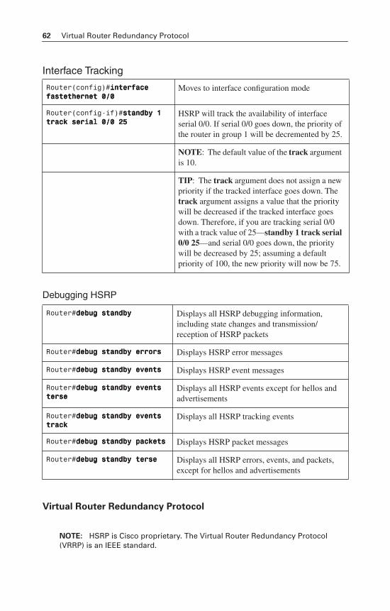
62 Virtual Router Redundancy Protocol
Interface Tracking
Debugging HSRP
Virtual Router Redundancy Protocol
NOTE: HSRP is Cisco proprietary. The Virtual Router Redundancy Protocol (VRRP) is an IEEE standard.
Router(config)#iiiinnnntttteeeerrrrffffaaaacccceeee ffffaaaasssstttteeeetttthhhheeeerrrrnnnneeeetttt 0000////0000
Moves to interface configuration mode
Router(config-if)#ssssttttaaaannnnddddbbbbyyyy 1111 ttttrrrraaaacccckkkk sssseeeerrrriiiiaaaallll 0000////0000 22225555
HSRP will track the availability of interface serial 0/0. If serial 0/0 goes down, the priority of the router in group 1 will be decremented by 25.
NOTE: The default value of the track argument is 10.
TIP: The track argument does not assign a new priority if the tracked interface goes down. The track argument assigns a value that the priority will be decreased if the tracked interface goes down. Therefore, if you are tracking serial 0/0 with a track value of 25—standby 1 track serial 0/0 25—and serial 0/0 goes down, the priority will be decreased by 25; assuming a default priority of 100, the new priority will now be 75.
Router#ddddeeeebbbbuuuugggg ssssttttaaaannnnddddbbbbyyyy Displays all HSRP debugging information, including state changes and transmission/reception of HSRP packets
Router#ddddeeeebbbbuuuugggg ssssttttaaaannnnddddbbbbyyyy eeeerrrrrrrroooorrrrssss Displays HSRP error messages
Router#ddddeeeebbbbuuuugggg ssssttttaaaannnnddddbbbbyyyy eeeevvvveeeennnnttttssss Displays HSRP event messages
Router#ddddeeeebbbbuuuugggg ssssttttaaaannnnddddbbbbyyyy eeeevvvveeeennnnttttssss tttteeeerrrrsssseeee
Displays all HSRP events except for hellos and advertisements
Router#ddddeeeebbbbuuuugggg ssssttttaaaannnnddddbbbbyyyy eeeevvvveeeennnnttttssss ttttrrrraaaacccckkkk
Displays all HSRP tracking events
Router#ddddeeeebbbbuuuugggg ssssttttaaaannnnddddbbbbyyyy ppppaaaacccckkkkeeeettttssss Displays HSRP packet messages
Router#ddddeeeebbbbuuuugggg ssssttttaaaannnnddddbbbbyyyy tttteeeerrrrsssseeee Displays all HSRP errors, events, and packets, except for hellos and advertisements
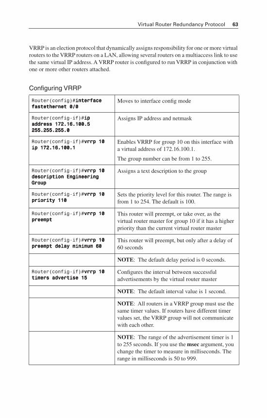
Virtual Router Redundancy Protocol 63
VRRP is an election protocol that dynamically assigns responsibility for one or more virtual routers to the VRRP routers on a LAN, allowing several routers on a multiaccess link to use the same virtual IP address. A VRRP router is configured to run VRRP in conjunction with one or more other routers attached.
Configuring VRRP
Router(config)#iiiinnnntttteeeerrrrffffaaaacccceeee ffffaaaasssstttteeeetttthhhheeeerrrrnnnneeeetttt 0000////0000
Moves to interface config mode
Router(config-if)#iiiipppp aaaaddddddddrrrreeeessssssss 111177772222....11116666....111100000000....5555 222255555555....222255555555....222255555555....0000
Assigns IP address and netmask
Router(config-if)#vvvvrrrrrrrrpppp 11110000 iiiipppp 111177772222....11116666....111100000000....1111
Enables VRRP for group 10 on this interface with a virtual address of 172.16.100.1.
The group number can be from 1 to 255.
Router(config-if)#vvvvrrrrrrrrpppp 11110000 ddddeeeessssccccrrrriiiippppttttiiiioooonnnn EEEEnnnnggggiiiinnnneeeeeeeerrrriiiinnnngggg GGGGrrrroooouuuupppp
Assigns a text description to the group
Router(config-if)#vvvvrrrrrrrrpppp 11110000 pppprrrriiiioooorrrriiiittttyyyy 111111110000
Sets the priority level for this router. The range is from 1 to 254. The default is 100.
Router(config-if)#vvvvrrrrrrrrpppp 11110000 pppprrrreeeeeeeemmmmpppptttt
This router will preempt, or take over, as the virtual router master for group 10 if it has a higher priority than the current virtual router master
Router(config-if)#vvvvrrrrrrrrpppp 11110000 pppprrrreeeeeeeemmmmpppptttt ddddeeeellllaaaayyyy mmmmiiiinnnniiiimmmmuuuummmm 66660000
This router will preempt, but only after a delay of 60 seconds
NOTE: The default delay period is 0 seconds.
Router(config-if)#vvvvrrrrrrrrpppp 11110000 ttttiiiimmmmeeeerrrrssss aaaaddddvvvveeeerrrrttttiiiisssseeee 11115555
Configures the interval between successful advertisements by the virtual router master
NOTE: The default interval value is 1 second.
NOTE: All routers in a VRRP group must use the same timer values. If routers have different timer values set, the VRRP group will not communicate with each other.
NOTE: The range of the advertisement timer is 1 to 255 seconds. If you use the msec argument, you change the timer to measure in milliseconds. The range in milliseconds is 50 to 999.
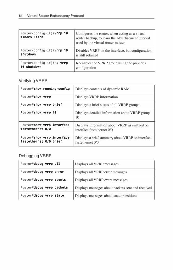
64 Virtual Router Redundancy Protocol
Verifying VRRP
Debugging VRRP
Router(config-if)#vvvvrrrrrrrrpppp 11110000 ttttiiiimmmmeeeerrrrssss lllleeeeaaaarrrrnnnn
Configures the router, when acting as a virtual router backup, to learn the advertisement interval used by the virtual router master
Router(config-if)#vvvvrrrrrrrrpppp 11110000 sssshhhhuuuuttttddddoooowwwwnnnn
Disables VRRP on the interface, but configuration is still retained
Router(config-if)#nnnnoooo vvvvrrrrrrrrpppp 11110000 sssshhhhuuuuttttddddoooowwwwnnnn
Reenables the VRRP group using the previous configuration
Router#sssshhhhoooowwww rrrruuuunnnnnnnniiiinnnngggg----ccccoooonnnnffffiiiigggg Displays contents of dynamic RAM
Router#sssshhhhoooowwww vvvvrrrrrrrrpppp Displays VRRP information
Router#sssshhhhoooowwww vvvvrrrrrrrrpppp bbbbrrrriiiieeeeffff Displays a brief status of all VRRP groups
Router#sssshhhhoooowwww vvvvrrrrrrrrpppp 11110000 Displays detailed information about VRRP group 10
Router#sssshhhhoooowwww vvvvrrrrrrrrpppp iiiinnnntttteeeerrrrffffaaaacccceeee ffffaaaasssstttteeeetttthhhheeeerrrrnnnneeeetttt 0000////0000
Displays information about VRRP as enabled on interface fastethernet 0/0
Router#sssshhhhoooowwww vvvvrrrrrrrrpppp iiiinnnntttteeeerrrrffffaaaacccceeee ffffaaaasssstttteeeetttthhhheeeerrrrnnnneeeetttt 0000////0000 bbbbrrrriiiieeeeffff
Displays a brief summary about VRRP on interface fastethernet 0/0
Router#ddddeeeebbbbuuuugggg vvvvrrrrrrrrpppp aaaallllllll Displays all VRRP messages
Router#ddddeeeebbbbuuuugggg vvvvrrrrrrrrpppp eeeerrrrrrrroooorrrr Displays all VRRP error messages
Router#ddddeeeebbbbuuuugggg vvvvrrrrrrrrpppp eeeevvvveeeennnnttttssss Displays all VRRP event messages
Router#ddddeeeebbbbuuuugggg vvvvrrrrrrrrpppp ppppaaaacccckkkkeeeettttssss Displays messages about packets sent and received
Router#ddddeeeebbbbuuuugggg vvvvrrrrrrrrpppp ssssttttaaaatttteeee Displays messages about state transitions
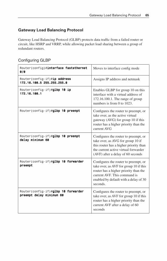
Gateway Load Balancing Protocol 65
Gateway Load Balancing Protocol
Gateway Load Balancing Protocol (GLBP) protects data traffic from a failed router or circuit, like HSRP and VRRP, while allowing packet load sharing between a group of redundant routers.
Configuring GLBP
Router(config)#iiiinnnntttteeeerrrrffffaaaacccceeee ffffaaaasssstttteeeetttthhhheeeerrrrnnnneeeetttt 0000////0000
Moves to interface config mode
Router(config-if)#iiiipppp aaaaddddddddrrrreeeessssssss 111177772222....11116666....111100000000....5555 222255555555....222255555555....222255555555....0000
Assigns IP address and netmask
Router(config-if)#ggggllllbbbbpppp 11110000 iiiipppp 111177772222....11116666....111100000000....1111
Enables GLBP for group 10 on this interface with a virtual address of 172.16.100.1. The range of group numbers is from 0 to 1023.
Router(config-if)#ggggllllbbbbpppp 11110000 pppprrrreeeeeeeemmmmpppptttt Configures the router to preempt, or take over, as the active virtual gateway (AVG) for group 10 if this router has a higher priority than the current AVG
Router(config-if)#ggggllllbbbbpppp 11110000 pppprrrreeeeeeeemmmmpppptttt ddddeeeellllaaaayyyy mmmmiiiinnnniiiimmmmuuuummmm 66660000
Configures the router to preempt, or take over, as AVG for group 10 if this router has a higher priority than the current active virtual forwarder (AVF) after a delay of 60 seconds
Router(config-if)#ggggllllbbbbpppp 11110000 ffffoooorrrrwwwwaaaarrrrddddeeeerrrr pppprrrreeeeeeeemmmmpppptttt
Configures the router to preempt, or take over, as AVF for group 10 if this router has a higher priority than the current AVF. This command is enabled by default with a delay of 30 seconds.
Router(config-if)#ggggllllbbbbpppp 11110000 ffffoooorrrrwwwwaaaarrrrddddeeeerrrr pppprrrreeeeeeeemmmmpppptttt ddddeeeellllaaaayyyy mmmmiiiinnnniiiimmmmuuuummmm 66660000
Configures the router to preempt, or take over, as AVF for group 10 if this router has a higher priority than the current AVF after a delay of 60 seconds
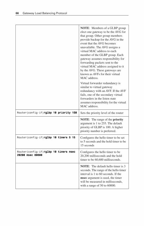
66 Gateway Load Balancing Protocol
NOTE: Members of a GLBP group elect one gateway to be the AVG for that group. Other group members provide backup for the AVG in the event that the AVG becomes unavailable. The AVG assigns a virtual MAC address to each member of the GLBP group. Each gateway assumes responsibility for forwarding packets sent to the virtual MAC address assigned to it by the AVG. These gateways are known as AVFs for their virtual MAC address.
Virtual forwarder redundancy is similar to virtual gateway redundancy with an AVF. If the AVF fails, one of the secondary virtual forwarders in the listen state assumes responsibility for the virtual MAC address.
Router(config-if)#ggggllllbbbbpppp 11110000 pppprrrriiiioooorrrriiiittttyyyy 111155550000 Sets the priority level of the router
NOTE: The range of the priorityargument is 1 to 255. The default priority of GLBP is 100. A higher priority number is preferred.
Router(config-if)#ggggllllbbbbpppp 11110000 ttttiiiimmmmeeeerrrrssss 5555 11115555 Configures the hello timer to be set to 5 seconds and the hold timer to be 15 seconds
Router(config-if)#ggggllllbbbbpppp 11110000 ttttiiiimmmmeeeerrrrssss mmmmsssseeeecccc 22220000222200000000 mmmmsssseeeecccc 66660000666600000000
Configures the hello timer to be 20,200 milliseconds and the hold timer to be 60,600 milliseconds.
NOTE: The default hello timer is 3 seconds. The range of the hello timer interval is 1 to 60 seconds. If the msec argument is used, the timer will be measured in milliseconds, with a range of 50 to 60000.
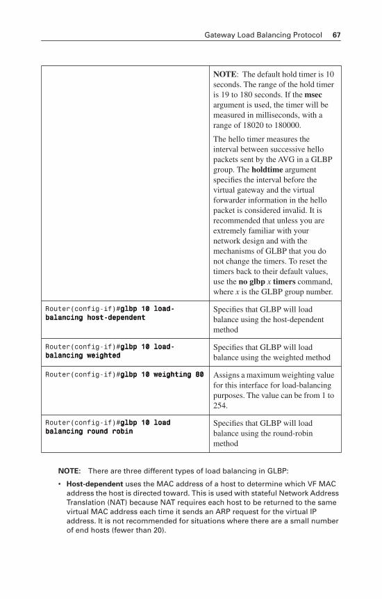
Gateway Load Balancing Protocol 67
NOTE: There are three different types of load balancing in GLBP:
• Host-dependent uses the MAC address of a host to determine which VF MAC address the host is directed toward. This is used with stateful Network Address Translation (NAT) because NAT requires each host to be returned to the same virtual MAC address each time it sends an ARP request for the virtual IP address. It is not recommended for situations where there are a small number of end hosts (fewer than 20).
NOTE: The default hold timer is 10 seconds. The range of the hold timer is 19 to 180 seconds. If the msecargument is used, the timer will be measured in milliseconds, with a range of 18020 to 180000.
The hello timer measures the interval between successive hello packets sent by the AVG in a GLBP group. The holdtime argument specifies the interval before the virtual gateway and the virtual forwarder information in the hello packet is considered invalid. It is recommended that unless you are extremely familiar with your network design and with the mechanisms of GLBP that you do not change the timers. To reset the timers back to their default values, use the no glbp x timers command,where x is the GLBP group number.
Router(config-if)#ggggllllbbbbpppp 11110000 llllooooaaaadddd----bbbbaaaallllaaaannnncccciiiinnnngggg hhhhoooosssstttt----ddddeeeeppppeeeennnnddddeeeennnntttt
Specifies that GLBP will load balance using the host-dependent method
Router(config-if)#ggggllllbbbbpppp 11110000 llllooooaaaadddd----bbbbaaaallllaaaannnncccciiiinnnngggg wwwweeeeiiiigggghhhhtttteeeedddd
Specifies that GLBP will load balance using the weighted method
Router(config-if)#ggggllllbbbbpppp 11110000 wwwweeeeiiiigggghhhhttttiiiinnnngggg 88880000 Assigns a maximum weighting value for this interface for load-balancing purposes. The value can be from 1 to 254.
Router(config-if)#ggggllllbbbbpppp 11110000 llllooooaaaadddd bbbbaaaallllaaaannnncccciiiinnnngggg rrrroooouuuunnnndddd rrrroooobbbbiiiinnnn
Specifies that GLBP will load balance using the round-robin method
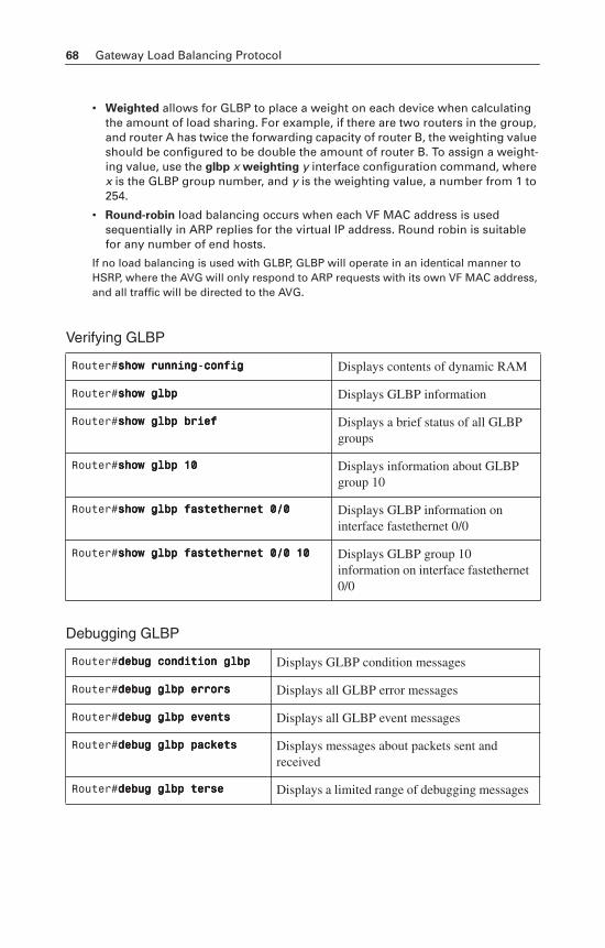
68 Gateway Load Balancing Protocol
• Weighted allows for GLBP to place a weight on each device when calculating the amount of load sharing. For example, if there are two routers in the group, and router A has twice the forwarding capacity of router B, the weighting value should be configured to be double the amount of router B. To assign a weight-ing value, use the glbp x weighting y interface configuration command, where x is the GLBP group number, and y is the weighting value, a number from 1 to 254.
• Round-robin load balancing occurs when each VF MAC address is used sequentially in ARP replies for the virtual IP address. Round robin is suitable for any number of end hosts.
If no load balancing is used with GLBP, GLBP will operate in an identical manner to HSRP, where the AVG will only respond to ARP requests with its own VF MAC address, and all traffic will be directed to the AVG.
Verifying GLBP
Debugging GLBP
Router#sssshhhhoooowwww rrrruuuunnnnnnnniiiinnnngggg----ccccoooonnnnffffiiiigggg Displays contents of dynamic RAM
Router#sssshhhhoooowwww ggggllllbbbbpppp Displays GLBP information
Router#sssshhhhoooowwww ggggllllbbbbpppp bbbbrrrriiiieeeeffff Displays a brief status of all GLBP groups
Router#sssshhhhoooowwww ggggllllbbbbpppp 11110000 Displays information about GLBP group 10
Router#sssshhhhoooowwww ggggllllbbbbpppp ffffaaaasssstttteeeetttthhhheeeerrrrnnnneeeetttt 0000////0000 Displays GLBP information on interface fastethernet 0/0
Router#sssshhhhoooowwww ggggllllbbbbpppp ffffaaaasssstttteeeetttthhhheeeerrrrnnnneeeetttt 0000////0000 11110000 Displays GLBP group 10 information on interface fastethernet 0/0
Router#ddddeeeebbbbuuuugggg ccccoooonnnnddddiiiittttiiiioooonnnn ggggllllbbbbpppp Displays GLBP condition messages
Router#ddddeeeebbbbuuuugggg ggggllllbbbbpppp eeeerrrrrrrroooorrrrssss Displays all GLBP error messages
Router#ddddeeeebbbbuuuugggg ggggllllbbbbpppp eeeevvvveeeennnnttttssss Displays all GLBP event messages
Router#ddddeeeebbbbuuuugggg ggggllllbbbbpppp ppppaaaacccckkkkeeeettttssss Displays messages about packets sent and received
Router#ddddeeeebbbbuuuugggg ggggllllbbbbpppp tttteeeerrrrsssseeee Displays a limited range of debugging messages
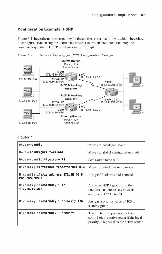
Configuration Example: HSRP 69
Configuration Example: HSRP
Figure 5-1 shows the network topology for the configuration that follows, which shows how to configure HSRP using the commands covered in this chapter. Note that only the commands specific to HSRP are shown in this example.
Figure 5-1 Network Topology for HSRP Configuration Example
Router 1
Router>eeeennnnaaaabbbblllleeee Moves to privileged mode
Router#ccccoooonnnnffffiiiigggguuuurrrreeee tttteeeerrrrmmmmiiiinnnnaaaallll Moves to global configuration mode
Router(config)#hhhhoooossssttttnnnnaaaammmmeeee RRRR1111 Sets router name to R1
R1(config)#iiiinnnntttteeeerrrrffffaaaacccceeee ffffaaaasssstttteeeetttthhhheeeerrrrnnnneeeetttt 0000////0000 Moves to interface config mode
R1(config-if)#iiiipppp aaaaddddddddrrrreeeessssssss 111177772222....11116666....11116666....5555 222255555555....222255555555....222255555555....0000
Assigns IP address and netmask
R1(config-if)#ssssttttaaaannnnddddbbbbyyyy 1111 iiiipppp 111177772222....11116666....11116666....222255554444
Activates HSRP group 1 on the interface and creates a virtual IP address of 172.16.6.254
R1(config-if)#ssssttttaaaannnnddddbbbbyyyy 1111 pppprrrriiiioooorrrriiiittttyyyy 111100005555 Assigns a priority value of 105 to standby group 1
R1(config-if)#ssssttttaaaannnnddddbbbbyyyy 1111 pppprrrreeeeeeeemmmmpppptttt This router will preempt, or take control of, the active router if the local priority is higher than the active router
s 0/0 DCE198.133.219.2/30
s 0/0198.133.219.1/30
fa 0/0172.16.16.5/24
Virtual IP172.16.16.254/24
fa 0/0172.16.16.6/24
Virtual IP172.16.16.254/24
s 0/0198.133.219.5/30
s 0/0 DCE198.133.219.6/30
S1
S2
172.16.16.1/24
WS1
172.16.16.2/24
WS2
172.16.16.3/24
WS3
R3Fa0/0 is trackingserial 0/1
Fa0/0 is trackingserial 0/0
Standby RouterPriority 100
Preempt is on
R2
Active RouterPriority 105
Preempt is on
R1
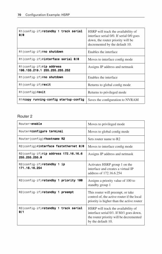
70 Configuration Example: HSRP
Router 2
R1(config-if)#ssssttttaaaannnnddddbbbbyyyy 1111 ttttrrrraaaacccckkkk sssseeeerrrriiiiaaaallll 0000////0000
HSRP will track the availability of interface serial 0/0. If serial 0/0 goes down, the router priority will be decremented by the default 10.
R1(config-if)#nnnnoooo sssshhhhuuuuttttddddoooowwwwnnnn Enables the interface
R1(config-if)#iiiinnnntttteeeerrrrffffaaaacccceeee sssseeeerrrriiiiaaaallll 0000////0000 Moves to interface config mode
R1(config-if)#iiiipppp aaaaddddddddrrrreeeessssssss 111199998888....111133333333....222211119999....1111 222255555555....222255555555....222255555555....222255552222
Assigns IP address and netmask
R1(config-if)#nnnnoooo sssshhhhuuuuttttddddoooowwwwnnnn Enables the interface
R1(config-if)#eeeexxxxiiiitttt Returns to global config mode
R1(config)#eeeexxxxiiiitttt Returns to privileged mode
R1#ccccooooppppyyyy rrrruuuunnnnnnnniiiinnnngggg----ccccoooonnnnffffiiiigggg ssssttttaaaarrrrttttuuuupppp----ccccoooonnnnffffiiiigggg Saves the configuration to NVRAM
Router>eeeennnnaaaabbbblllleeee Moves to privileged mode
Router#ccccoooonnnnffffiiiigggguuuurrrreeee tttteeeerrrrmmmmiiiinnnnaaaallll Moves to global config mode
Router(config)#hhhhoooossssttttnnnnaaaammmmeeee RRRR2222 Sets router name to R2
R2(config)#iiiinnnntttteeeerrrrffffaaaacccceeee ffffaaaasssstttteeeetttthhhheeeerrrrnnnneeeetttt 0000////0000 Moves to interface config mode
R2(config-if)#iiiipppp aaaaddddddddrrrreeeessssssss 111177772222....11116666....11116666....6666 222255555555....222255555555....222255555555....0000
Assigns IP address and netmask
R2(config-if)#ssssttttaaaannnnddddbbbbyyyy 1111 iiiipppp 111177771111....11116666....11116666....222255554444
Activates HSRP group 1 on the interface and creates a virtual IP address of 172.16.6.254
R2(config-if)#ssssttttaaaannnnddddbbbbyyyy 1111 pppprrrriiiioooorrrriiiittttyyyy 111100000000 Assigns a priority value of 100 to standby group 1
R2(config-if)#ssssttttaaaannnnddddbbbbyyyy 1111 pppprrrreeeeeeeemmmmpppptttt This router will preempt, or take control of, the active router if the local priority is higher than the active router
R2(config-if)#ssssttttaaaannnnddddbbbbyyyy 1111 ttttrrrraaaacccckkkk sssseeeerrrriiiiaaaallll 0000////1111
HSRP will track the availability of interface serial 0/1. If S0/1 goes down, the router priority will be decremented by the default 10.
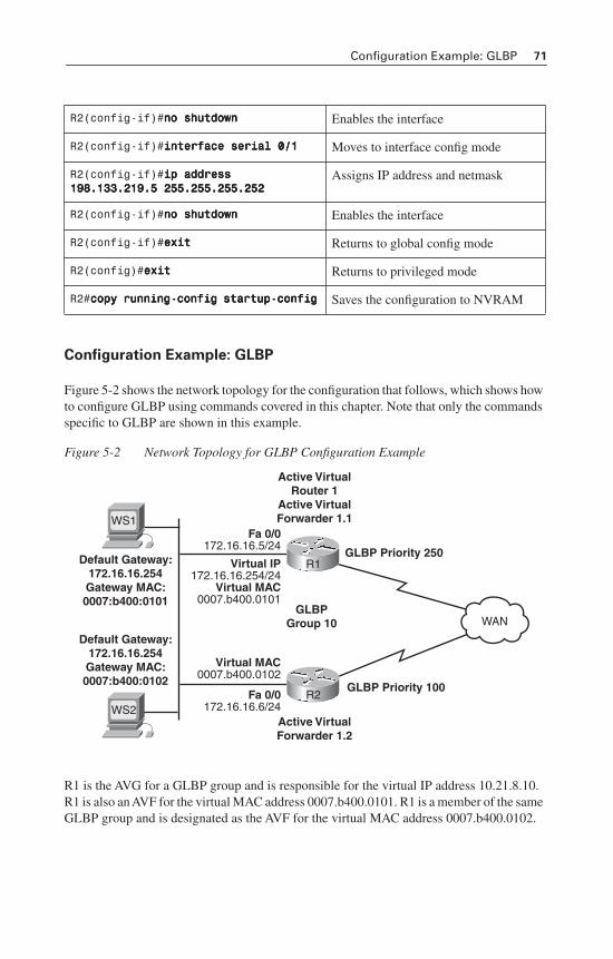
Configuration Example: GLBP 71
Configuration Example: GLBP
Figure 5-2 shows the network topology for the configuration that follows, which shows how to configure GLBP using commands covered in this chapter. Note that only the commands specific to GLBP are shown in this example.
Figure 5-2 Network Topology for GLBP Configuration Example
R1 is the AVG for a GLBP group and is responsible for the virtual IP address 10.21.8.10. R1 is also an AVF for the virtual MAC address 0007.b400.0101. R1 is a member of the same GLBP group and is designated as the AVF for the virtual MAC address 0007.b400.0102.
R2(config-if)#nnnnoooo sssshhhhuuuuttttddddoooowwwwnnnn Enables the interface
R2(config-if)#iiiinnnntttteeeerrrrffffaaaacccceeee sssseeeerrrriiiiaaaallll 0000////1111 Moves to interface config mode
R2(config-if)#iiiipppp aaaaddddddddrrrreeeessssssss 111199998888....111133333333....222211119999....5555 222255555555....222255555555....222255555555....222255552222
Assigns IP address and netmask
R2(config-if)#nnnnoooo sssshhhhuuuuttttddddoooowwwwnnnn Enables the interface
R2(config-if)#eeeexxxxiiiitttt Returns to global config mode
R2(config)#eeeexxxxiiiitttt Returns to privileged mode
R2#ccccooooppppyyyy rrrruuuunnnnnnnniiiinnnngggg----ccccoooonnnnffffiiiigggg ssssttttaaaarrrrttttuuuupppp----ccccoooonnnnffffiiiigggg Saves the configuration to NVRAM
GLBP Priority 250
Fa 0/0172.16.16.5/24
Virtual MAC0007.b400.0102
Fa 0/0172.16.16.6/24
Virtual IP172.16.16.254/24
Virtual MAC0007.b400.0101
GLBP Priority 100
Default Gateway:172.16.16.254Gateway MAC:0007:b400:0101
WS1
Default Gateway:172.16.16.254Gateway MAC:0007:b400:0102
WS2
GLBPGroup 10
Active VirtualForwarder 1.2
R2
Active VirtualRouter 1
Active VirtualForwarder 1.1
R1
WAN
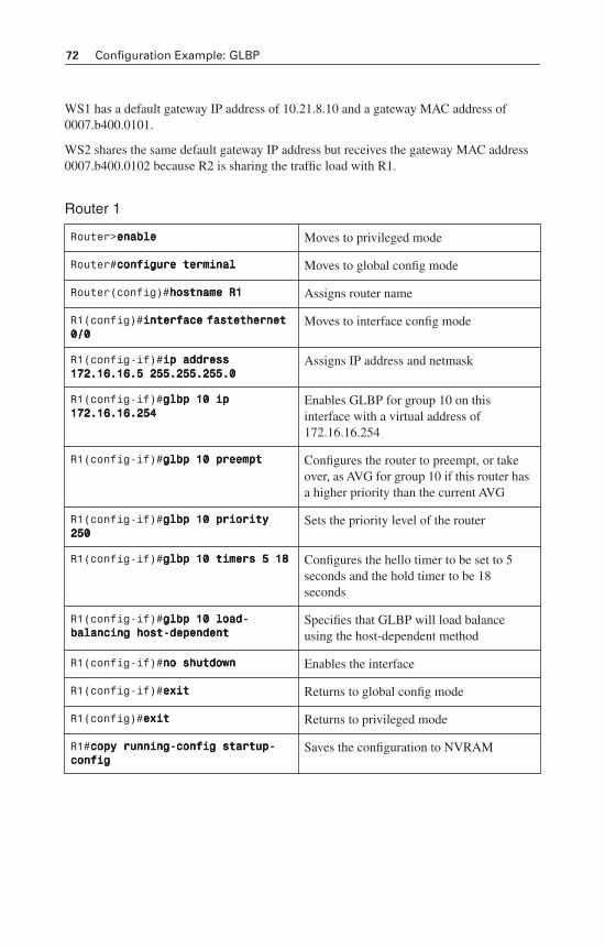
72 Configuration Example: GLBP
WS1 has a default gateway IP address of 10.21.8.10 and a gateway MAC address of 0007.b400.0101.
WS2 shares the same default gateway IP address but receives the gateway MAC address 0007.b400.0102 because R2 is sharing the traffic load with R1.
Router 1
Router>eeeennnnaaaabbbblllleeee Moves to privileged mode
Router#ccccoooonnnnffffiiiigggguuuurrrreeee tttteeeerrrrmmmmiiiinnnnaaaallll Moves to global config mode
Router(config)#hhhhoooossssttttnnnnaaaammmmeeee RRRR1111 Assigns router name
R1(config)#iiiinnnntttteeeerrrrffffaaaacccceeee ffffaaaasssstttteeeetttthhhheeeerrrrnnnneeeetttt 0000////0000
Moves to interface config mode
R1(config-if)#iiiipppp aaaaddddddddrrrreeeessssssss 111177772222....11116666....11116666....5555 222255555555....222255555555....222255555555....0000
Assigns IP address and netmask
R1(config-if)#ggggllllbbbbpppp 11110000 iiiipppp 111177772222....11116666....11116666....222255554444
Enables GLBP for group 10 on this interface with a virtual address of 172.16.16.254
R1(config-if)#ggggllllbbbbpppp 11110000 pppprrrreeeeeeeemmmmpppptttt Configures the router to preempt, or take over, as AVG for group 10 if this router has a higher priority than the current AVG
R1(config-if)#ggggllllbbbbpppp 11110000 pppprrrriiiioooorrrriiiittttyyyy 222255550000
Sets the priority level of the router
R1(config-if)#ggggllllbbbbpppp 11110000 ttttiiiimmmmeeeerrrrssss 5555 11118888 Configures the hello timer to be set to 5 seconds and the hold timer to be 18 seconds
R1(config-if)#ggggllllbbbbpppp 11110000 llllooooaaaadddd----bbbbaaaallllaaaannnncccciiiinnnngggg hhhhoooosssstttt----ddddeeeeppppeeeennnnddddeeeennnntttt
Specifies that GLBP will load balance using the host-dependent method
R1(config-if)#nnnnoooo sssshhhhuuuuttttddddoooowwwwnnnn Enables the interface
R1(config-if)#eeeexxxxiiiitttt Returns to global config mode
R1(config)#eeeexxxxiiiitttt Returns to privileged mode
R1#ccccooooppppyyyy rrrruuuunnnnnnnniiiinnnngggg----ccccoooonnnnffffiiiigggg ssssttttaaaarrrrttttuuuupppp----ccccoooonnnnffffiiiigggg
Saves the configuration to NVRAM
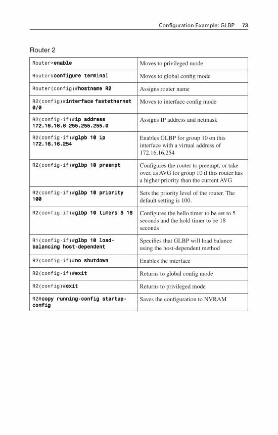
Configuration Example: GLBP 73
Router 2
Router>eeeennnnaaaabbbblllleeee Moves to privileged mode
Router#ccccoooonnnnffffiiiigggguuuurrrreeee tttteeeerrrrmmmmiiiinnnnaaaallll Moves to global config mode
Router(config)#hhhhoooossssttttnnnnaaaammmmeeee RRRR2222 Assigns router name
R2(config)#iiiinnnntttteeeerrrrffffaaaacccceeee ffffaaaasssstttteeeetttthhhheeeerrrrnnnneeeetttt 0000////0000
Moves to interface config mode
R2(config-if)#iiiipppp aaaaddddddddrrrreeeessssssss 111177772222....11116666....11116666....6666 222255555555....222255555555....222255555555....0000
Assigns IP address and netmask
R2(config-if)#ggggllllppppbbbb 11110000 iiiipppp 111177772222....11116666....11116666....222255554444
Enables GLBP for group 10 on this interface with a virtual address of 172.16.16.254
R2(config-if)#ggggllllbbbbpppp 11110000 pppprrrreeeeeeeemmmmpppptttt Configures the router to preempt, or take over, as AVG for group 10 if this router has a higher priority than the current AVG
R2(config-if)#ggggllllbbbbpppp 11110000 pppprrrriiiioooorrrriiiittttyyyy 111100000000
Sets the priority level of the router. The default setting is 100.
R2(config-if)#ggggllllbbbbpppp 11110000 ttttiiiimmmmeeeerrrrssss 5555 11118888 Configures the hello timer to be set to 5 seconds and the hold timer to be 18 seconds
R1(config-if)#ggggllllbbbbpppp 11110000 llllooooaaaadddd----bbbbaaaallllaaaannnncccciiiinnnngggg hhhhoooosssstttt----ddddeeeeppppeeeennnnddddeeeennnntttt
Specifies that GLBP will load balance using the host-dependent method
R2(config-if)#nnnnoooo sssshhhhuuuuttttddddoooowwwwnnnn Enables the interface
R2(config-if)#eeeexxxxiiiitttt Returns to global config mode
R2(config)#eeeexxxxiiiitttt Returns to privileged mode
R2#ccccooooppppyyyy rrrruuuunnnnnnnniiiinnnngggg----ccccoooonnnnffffiiiigggg ssssttttaaaarrrrttttuuuupppp----ccccoooonnnnffffiiiigggg
Saves the configuration to NVRAM

This page intentionally left blank
CHAPTER 6
Wireless Client Access
This chapter provides information and commands concerning the following topics:
• Configuration Example: 4402 WLAN Controller Using the Configuration Wizard—Covers the tasks and command-line interface (CLI) commands to
— Assign a host name to the wireless LAN controller (WLC)
— Enable Telnet access to the WLC
— Enable HTTP access to the WLC
— Set a timeout of the CLI
— Save a configuration
— Verify the configuration
• Configuration Example: 4402 WLAN Controller Using the Web Interface—Covers the same tasks as listed above in the CLI, but with the graphical user interface (GUI)
• Configuration Example: Configuring a 3560 Switch to Support WLANs and APs—Covers how to configure a 3560 switch to support wireless LANs (WLAN) and access points (AP)
• Configuration Example: Configuring a Wireless Client—Covers how to configure a Cisco Aironet wireless client adapter
Configuration Example: 4402 WLAN Controller Using the
Configuration Wizard
NOTE: In the Wireless LAN Controller (WLC) Configuration Wizard, all available options appear in brackets after each parameter. The default value appears in all uppercase letters.
Commands are case sensitive.
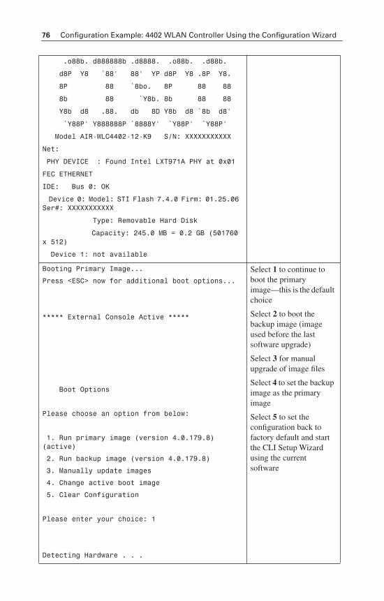
76 Configuration Example: 4402 WLAN Controller Using the Configuration Wizard
.o88b. d888888b .d8888. .o88b. .d88b.
d8P Y8 `88' 88' YP d8P Y8 .8P Y8.
8P 88 `8bo. 8P 88 88
8b 88 `Y8b. 8b 88 88
Y8b d8 .88. db 8D Y8b d8 `8b d8'
`Y88P' Y888888P `8888Y' `Y88P' `Y88P'
Model AIR-WLC4402-12-K9 S/N: XXXXXXXXXXX
Net:
PHY DEVICE : Found Intel LXT971A PHY at 0x01
FEC ETHERNET
IDE: Bus 0: OK
Device 0: Model: STI Flash 7.4.0 Firm: 01.25.06 Ser#: XXXXXXXXXXX
Type: Removable Hard Disk
Capacity: 245.0 MB = 0.2 GB (501760 x 512)
Device 1: not available
Booting Primary Image...
Press <ESC> now for additional boot options...
***** External Console Active *****
Boot Options
Please choose an option from below:
1. Run primary image (version 4.0.179.8) (active)
2. Run backup image (version 4.0.179.8)
3. Manually update images
4. Change active boot image
5. Clear Configuration
Please enter your choice: 1
Detecting Hardware . . .
Select 1 to continue to boot the primary image—this is the default choice
Select 2 to boot the backup image (image used before the last software upgrade)
Select 3 for manual upgrade of image files
Select 4 to set the backup image as the primary image
Select 5 to set the configuration back to factory default and start the CLI Setup Wizard using the current software
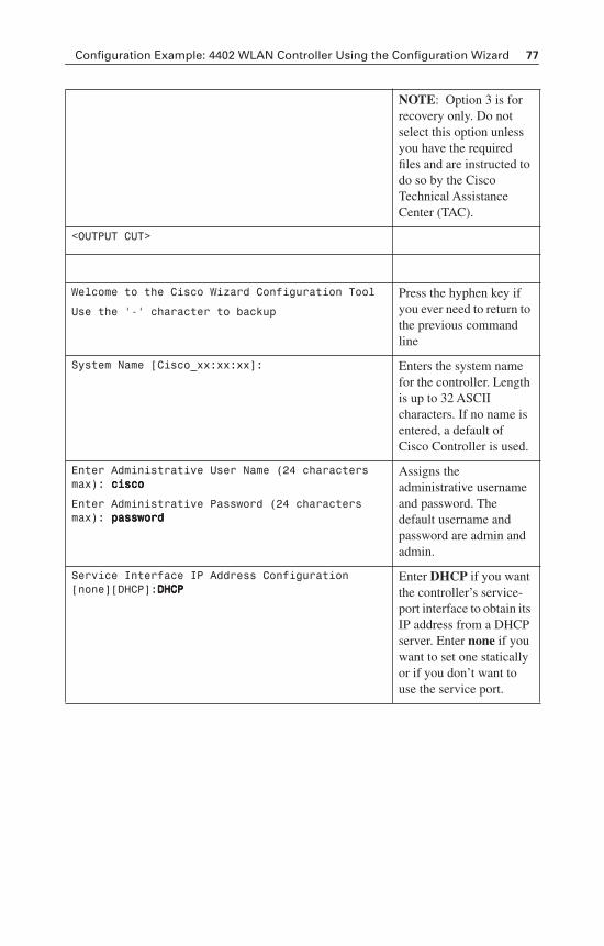
Configuration Example: 4402 WLAN Controller Using the Configuration Wizard 77
NOTE: Option 3 is for recovery only. Do not select this option unless you have the required files and are instructed to do so by the Cisco Technical Assistance Center (TAC).
<OUTPUT CUT>
Welcome to the Cisco Wizard Configuration Tool
Use the '-' character to backup
Press the hyphen key if you ever need to return to the previous command line
System Name [Cisco_xx:xx:xx]: Enters the system name for the controller. Length is up to 32 ASCII characters. If no name is entered, a default of Cisco Controller is used.
Enter Administrative User Name (24 characters max): cccciiiissssccccoooo
Enter Administrative Password (24 characters max): ppppaaaasssssssswwwwoooorrrrdddd
Assigns the administrative username and password. The default username and password are admin and admin.
Service Interface IP Address Configuration [none][DHCP]:DDDDHHHHCCCCPPPP
Enter DHCP if you want the controller’s service-port interface to obtain its IP address from a DHCP server. Enter none if you want to set one statically or if you don’t want to use the service port.
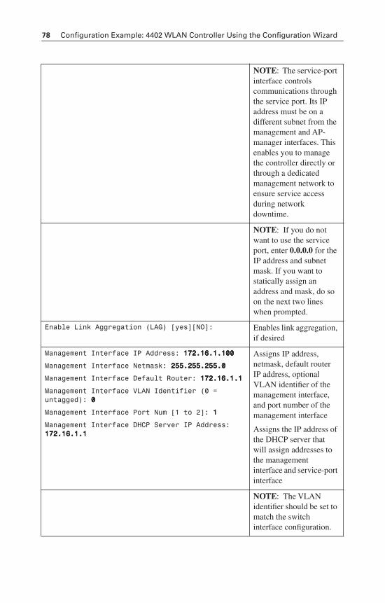
78 Configuration Example: 4402 WLAN Controller Using the Configuration Wizard
NOTE: The service-port interface controls communications through the service port. Its IP address must be on a different subnet from the management and AP-manager interfaces. This enables you to manage the controller directly or through a dedicated management network to ensure service access during network downtime.
NOTE: If you do not want to use the service port, enter 0.0.0.0 for the IP address and subnet mask. If you want to statically assign an address and mask, do so on the next two lines when prompted.
Enable Link Aggregation (LAG) [yes][NO]: Enables link aggregation, if desired
Management Interface IP Address: 111177772222....11116666....1111....111100000000
Management Interface Netmask: 222255555555....222255555555....222255555555....0000
Management Interface Default Router: 111177772222....11116666....1111....1111
Management Interface VLAN Identifier (0 = untagged): 0000
Management Interface Port Num [1 to 2]: 1111
Management Interface DHCP Server IP Address: 111177772222....11116666....1111....1111
Assigns IP address, netmask, default router IP address, optional VLAN identifier of the management interface, and port number of the management interface
Assigns the IP address of the DHCP server that will assign addresses to the management interface and service-port interface
NOTE: The VLAN identifier should be set to match the switch interface configuration.
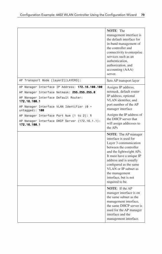
Configuration Example: 4402 WLAN Controller Using the Configuration Wizard 79
NOTE: The management interface is the default interface for in-band management of the controller and connectivity to enterprise services such as an authentication,authorization, and accounting (AAA) server.
AP Transport Mode [layer2][LAYER3]: Sets AP transport layer
AP Manager Interface IP Address: 111177772222....11116666....111100000000....111100000000
AP Manager Interface Netmask: 222255555555....222255555555....222255555555....0000
AP Manager Interface Default Router: 111177772222....11116666....111100000000....1111
AP Manager Interface VLAN Identifier (0 = untagged): 111100000000
AP Manager Interface Port Num [1 to 2]: 1111
AP Manager Interface DHCP Server (172.16.1.1): 111177772222....11116666....111100000000....1111
Assigns IP address, netmask, default router IP address, optional VLAN identifier, and port number of the AP manager interface
Assigns the IP address of the DHCP server that will assign addresses to the APs
NOTE: The AP manager interface is used for Layer 3 communication between the controller and the lightweight APs. It must have a unique IP address and is usually configured as the same VLAN or IP subnet as the management interface, but is not required to be.
NOTE: If the AP manager interface is on the same subnet as the management interface, the same DHCP server is used for the AP manager interface and the management interface.
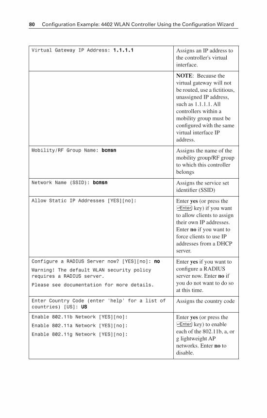
80 Configuration Example: 4402 WLAN Controller Using the Configuration Wizard
Virtual Gateway IP Address: 1111....1111....1111....1111 Assigns an IP address to the controller's virtual interface.
NOTE: Because the virtual gateway will not be routed, use a fictitious, unassigned IP address, such as 1.1.1.1. All controllers within a mobility group must be configured with the same virtual interface IP address.
Mobility/RF Group Name: bbbbccccmmmmssssnnnn Assigns the name of the mobility group/RF group to which this controller belongs
Network Name (SSID): bbbbccccmmmmssssnnnn Assigns the service set identifier (SSID)
Allow Static IP Addresses [YES][no]: Enter yes (or press the ® key) if you want to allow clients to assign their own IP addresses. Enter no if you want to force clients to use IP addresses from a DHCP server.
Configure a RADIUS Server now? [YES][no]: nnnnoooo
Warning! The default WLAN security policy requires a RADIUS server.
Please see documentation for more details.
Enter yes if you want to configure a RADIUS server now. Enter no if you do not want to do so at this time.
Enter Country Code (enter 'help' for a list of countries) [US]: UUUUSSSS
Assigns the country code
Enable 802.11b Network [YES][no]:
Enable 802.11a Network [YES][no]:
Enable 802.11g Network [YES][no]:
Enter yes (or press the ® key) to enable each of the 802.11b, a, or g lightweight AP networks. Enter no to disable.
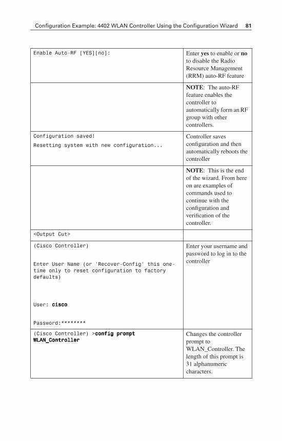
Configuration Example: 4402 WLAN Controller Using the Configuration Wizard 81
Enable Auto-RF [YES][no]: Enter yes to enable or noto disable the Radio Resource Management (RRM) auto-RF feature
NOTE: The auto-RF feature enables the controller to automatically form an RF group with other controllers.
Configuration saved!
Resetting system with new configuration...
Controller saves configuration and then automatically reboots the controller
NOTE: This is the end of the wizard. From here on are examples of commands used to continue with the configuration and verification of the controller.
<Output Cut>
(Cisco Controller)
Enter User Name (or 'Recover-Config' this one-time only to reset configuration to factory defaults)
User: cccciiiissssccccoooo
Password:********
Enter your username and password to log in to the controller
(Cisco Controller) >ccccoooonnnnffffiiiigggg pppprrrroooommmmpppptttt WWWWLLLLAAAANNNN____CCCCoooonnnnttttrrrroooolllllllleeeerrrr
Changes the controller prompt to WLAN_Controller. The length of this prompt is 31 alphanumeric characters.
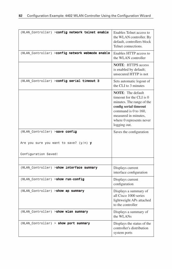
82 Configuration Example: 4402 WLAN Controller Using the Configuration Wizard
(WLAN_Controller) >ccccoooonnnnffffiiiigggg nnnneeeettttwwwwoooorrrrkkkk tttteeeellllnnnneeeetttt eeeennnnaaaabbbblllleeee Enables Telnet access to the WLAN controller. By default, controllers block Telnet connections.
(WLAN_Controller) >ccccoooonnnnffffiiiigggg nnnneeeettttwwwwoooorrrrkkkk wwwweeeebbbbmmmmooooddddeeee eeeennnnaaaabbbblllleeee Enables HTTP access to the WLAN controller
NOTE: HTTPS access is enabled by default; unsecured HTTP is not
(WLAN_Controller) >ccccoooonnnnffffiiiigggg sssseeeerrrriiiiaaaallll ttttiiiimmmmeeeeoooouuuutttt 3333 Sets automatic logout of the CLI to 3 minutes
NOTE: The default timeout for the CLI is 0 minutes. The range of the config serial timeoutcommand is 0 to 160, measured in minutes, where 0 represents never logging out.
(WLAN_Controller) >ssssaaaavvvveeee ccccoooonnnnffffiiiigggg
Are you sure you want to save? (y/n) yyyy
Configuration Saved!
Saves the configuration
(WLAN_Controller) >sssshhhhoooowwww iiiinnnntttteeeerrrrffffaaaacccceeee ssssuuuummmmmmmmaaaarrrryyyy Displays current interface configuration
(WLAN_Controller) >sssshhhhoooowwww rrrruuuunnnn----ccccoooonnnnffffiiiigggg Displays current configuration
(WLAN_Controller) >sssshhhhoooowwww aaaapppp ssssuuuummmmmmmmaaaarrrryyyy Displays a summary of all Cisco 1000 series lightweight APs attached to the controller
(WLAN_Controller) >sssshhhhoooowwww wwwwllllaaaannnn ssssuuuummmmmmmmaaaarrrryyyy Displays a summary of the WLANs
(WLAN_Controller) > sssshhhhoooowwww ppppoooorrrrtttt ssssuuuummmmmmmmaaaarrrryyyy Displays the status of the controller's distribution system ports
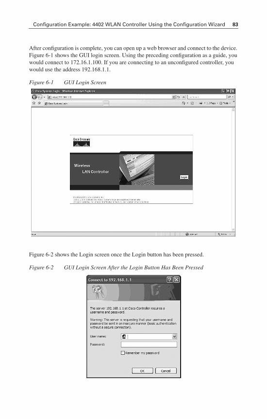
Configuration Example: 4402 WLAN Controller Using the Configuration Wizard 83
After configuration is complete, you can open up a web browser and connect to the device. Figure 6-1 shows the GUI login screen. Using the preceding configuration as a guide, you would connect to 172.16.1.100. If you are connecting to an unconfigured controller, you would use the address 192.168.1.1.
Figure 6-1 GUI Login Screen
Figure 6-2 shows the Login screen once the Login button has been pressed.
Figure 6-2 GUI Login Screen After the Login Button Has Been Pressed
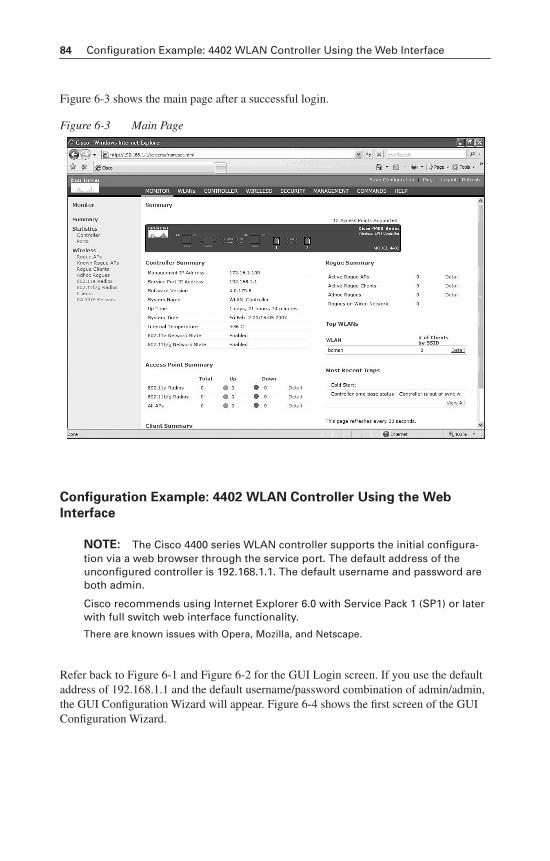
84 Configuration Example: 4402 WLAN Controller Using the Web Interface
Figure 6-3 shows the main page after a successful login.
Figure 6-3 Main Page
Configuration Example: 4402 WLAN Controller Using the Web
Interface
NOTE: The Cisco 4400 series WLAN controller supports the initial configura-tion via a web browser through the service port. The default address of the unconfigured controller is 192.168.1.1. The default username and password are both admin.
Cisco recommends using Internet Explorer 6.0 with Service Pack 1 (SP1) or later with full switch web interface functionality.
There are known issues with Opera, Mozilla, and Netscape.
Refer back to Figure 6-1 and Figure 6-2 for the GUI Login screen. If you use the default address of 192.168.1.1 and the default username/password combination of admin/admin, the GUI Configuration Wizard will appear. Figure 6-4 shows the first screen of the GUI Configuration Wizard.
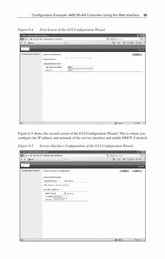
Configuration Example: 4402 WLAN Controller Using the Web Interface 85
Figure 6-4 First Screen of the GUI Configuration Wizard
Figure 6-5 shows the second screen of the GUI Configuration Wizard. This is where you configure the IP address and netmask of the service interface and enable DHCP, if desired.
Figure 6-5 Service Interface Configuration of the GUI Configuration Wizard
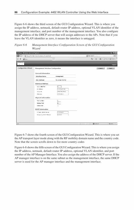
86 Configuration Example: 4402 WLAN Controller Using the Web Interface
Figure 6-6 shows the third screen of the GUI Configuration Wizard. This is where you assign the IP address, netmask, default router IP address, optional VLAN identifier of the management interface, and port number of the management interface. You also configure the IP address of the DHCP server that will assign addresses to the APs. Note that if you leave the VLAN identifier as zero, it means the interface is untagged.
Figure 6-6 Management Interface Configuration Screen of the GUI Configuration Wizard
Figure 6-7 shows the fourth screen of the GUI Configuration Wizard. This is where you set the AP transport layer mode along with the RF mobility domain name and the country code. Note that the screen scrolls down to list more country codes
Figure 6-8 shows the fifth screen of the GUI Configuration Wizard. This is where you assign the IP address, netmask, default router IP address, optional VLAN identifier, and port number of the AP Manager Interface. You also assign the address of the DHCP server. If the AP manager interface is on the same subnet as the management interface, the same DHCP server is used for the AP manager interface and the management interface.
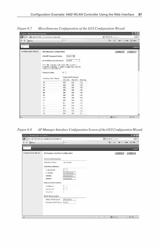
Configuration Example: 4402 WLAN Controller Using the Web Interface 87
Figure 6-7 Miscellaneous Configuration of the GUI Configuration Wizard
Figure 6-8 AP Manager Interface Configuration Screen of the GUI Configuration Wizard
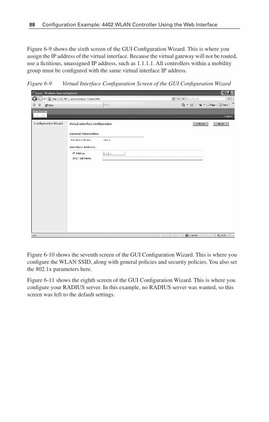
88 Configuration Example: 4402 WLAN Controller Using the Web Interface
Figure 6-9 shows the sixth screen of the GUI Configuration Wizard. This is where you assign the IP address of the virtual interface. Because the virtual gateway will not be routed, use a fictitious, unassigned IP address, such as 1.1.1.1. All controllers within a mobility group must be configured with the same virtual interface IP address.
Figure 6-9 Virtual Interface Configuration Screen of the GUI Configuration Wizard
Figure 6-10 shows the seventh screen of the GUI Configuration Wizard. This is where you configure the WLAN SSID, along with general policies and security policies. You also set the 802.1x parameters here.
Figure 6-11 shows the eighth screen of the GUI Configuration Wizard. This is where you configure your RADIUS server. In this example, no RADIUS server was wanted, so this screen was left to the default settings.
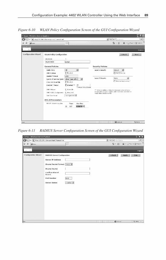
Configuration Example: 4402 WLAN Controller Using the Web Interface 89
Figure 6-10 WLAN Policy Configuration Screen of the GUI Configuration Wizard
Figure 6-11 RADIUS Server Configuration Screen of the GUI Configuration Wizard
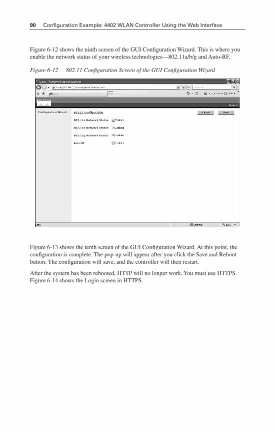
90 Configuration Example: 4402 WLAN Controller Using the Web Interface
Figure 6-12 shows the ninth screen of the GUI Configuration Wizard. This is where you enable the network status of your wireless technologies—802.11a/b/g and Auto-RF.
Figure 6-12 802.11 Configuration Screen of the GUI Configuration Wizard
Figure 6-13 shows the tenth screen of the GUI Configuration Wizard. At this point, the configuration is complete. The pop-up will appear after you click the Save and Reboot button. The configuration will save, and the controller will then restart.
After the system has been rebooted, HTTP will no longer work. You must use HTTPS. Figure 6-14 shows the Login screen in HTTPS.
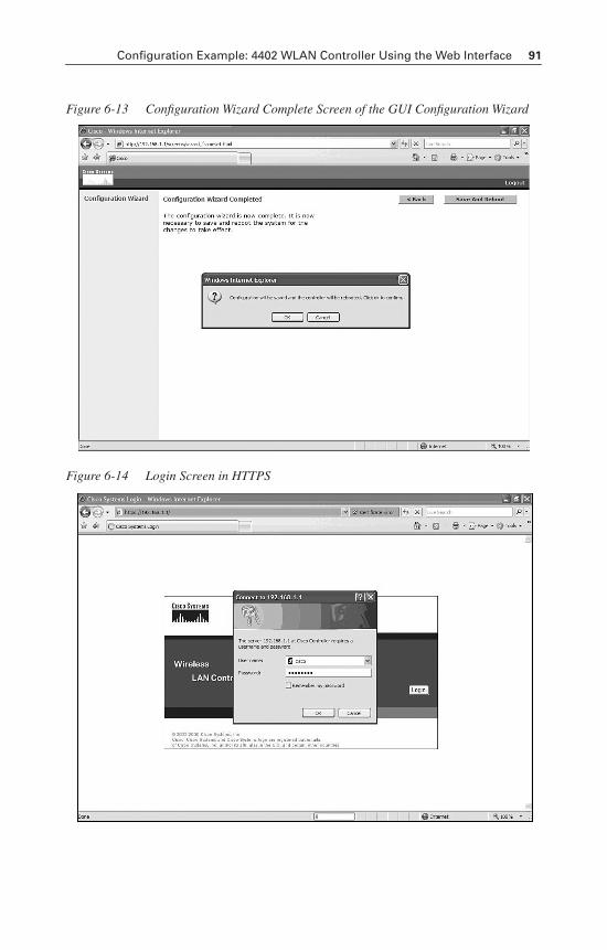
Configuration Example: 4402 WLAN Controller Using the Web Interface 91
Figure 6-13 Configuration Wizard Complete Screen of the GUI Configuration Wizard
Figure 6-14 Login Screen in HTTPS
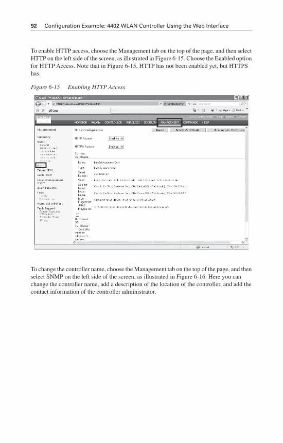
92 Configuration Example: 4402 WLAN Controller Using the Web Interface
To enable HTTP access, choose the Management tab on the top of the page, and then select HTTP on the left side of the screen, as illustrated in Figure 6-15. Choose the Enabled option for HTTP Access. Note that in Figure 6-15, HTTP has not been enabled yet, but HTTPS has.
Figure 6-15 Enabling HTTP Access
To change the controller name, choose the Management tab on the top of the page, and then select SNMP on the left side of the screen, as illustrated in Figure 6-16. Here you can change the controller name, add a description of the location of the controller, and add the contact information of the controller administrator.
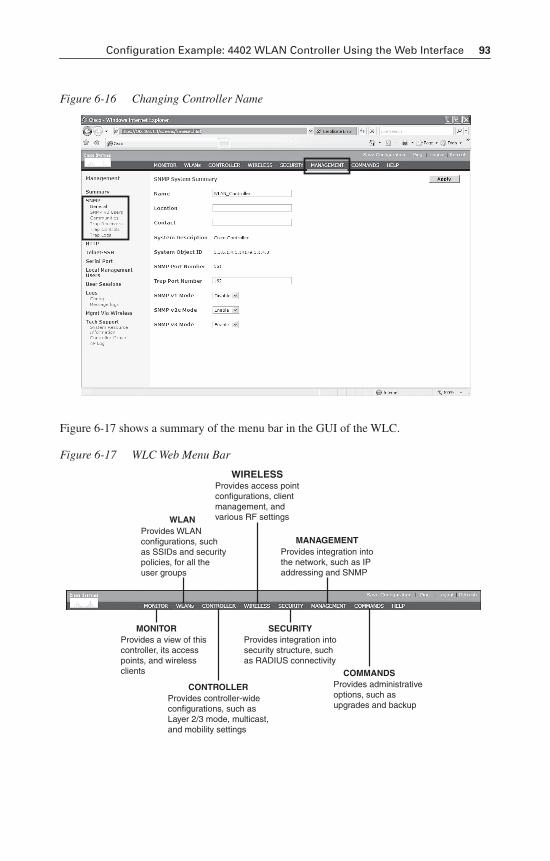
Configuration Example: 4402 WLAN Controller Using the Web Interface 93
Figure 6-16 Changing Controller Name
Figure 6-17 shows a summary of the menu bar in the GUI of the WLC.
Figure 6-17 WLC Web Menu Bar
WLANProvides WLANconfigurations, suchas SSIDs and securitypolicies, for all theuser groups
MONITORProvides a view of thiscontroller, its accesspoints, and wirelessclients
MANAGEMENTProvides integration intothe network, such as IPaddressing and SNMP
WIRELESSProvides access pointconfigurations, clientmanagement, andvarious RF settings
CONTROLLERProvides controller-wideconfigurations, such asLayer 2/3 mode, multicast,and mobility settings
SECURITYProvides integration intosecurity structure, suchas RADIUS connectivity
COMMANDSProvides administrativeoptions, such asupgrades and backup
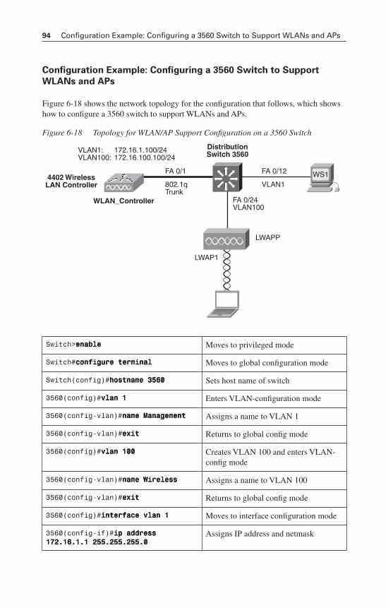
94 Configuration Example: Configuring a 3560 Switch to Support WLANs and APs
Configuration Example: Configuring a 3560 Switch to Support
WLANs and APs
Figure 6-18 shows the network topology for the configuration that follows, which shows how to configure a 3560 switch to support WLANs and APs.
Figure 6-18 Topology for WLAN/AP Support Configuration on a 3560 Switch
Switch>eeeennnnaaaabbbblllleeee Moves to privileged mode
Switch#ccccoooonnnnffffiiiigggguuuurrrreeee tttteeeerrrrmmmmiiiinnnnaaaallll Moves to global configuration mode
Switch(config)#hhhhoooossssttttnnnnaaaammmmeeee 3333555566660000 Sets host name of switch
3560(config)#vvvvllllaaaannnn 1111 Enters VLAN-configuration mode
3560(config-vlan)#nnnnaaaammmmeeee MMMMaaaannnnaaaaggggeeeemmmmeeeennnntttt Assigns a name to VLAN 1
3560(config-vlan)#eeeexxxxiiiitttt Returns to global config mode
3560(config)#vvvvllllaaaannnn 111100000000 Creates VLAN 100 and enters VLAN-config mode
3560(config-vlan)#nnnnaaaammmmeeee WWWWiiiirrrreeeelllleeeessssssss Assigns a name to VLAN 100
3560(config-vlan)#eeeexxxxiiiitttt Returns to global config mode
3560(config)#iiiinnnntttteeeerrrrffffaaaacccceeee vvvvllllaaaannnn 1111 Moves to interface configuration mode
3560(config-if)#iiiipppp aaaaddddddddrrrreeeessssssss 111177772222....11116666....1111....1111 222255555555....222255555555....222255555555....0000
Assigns IP address and netmask
FA 0/24VLAN100
DistributionSwitch 3560
4402 WirelessLAN Controller
FA 0/12FA 0/1
172.16.1.100/24172.16.100.100/24
VLAN1:VLAN100:
VLAN1802.1qTrunk
WS1
WLAN_Controller
LWAP1
LWAPP
Configuration Example: Configuring a 3560 Switch to Support WLANs and APs 95
3560(config-if)#nnnnoooo sssshhhhuuuuttttddddoooowwwwnnnn Enables the interface
3560(config-if)#iiiinnnntttteeeerrrrffffaaaacccceeee vvvvllllaaaannnn 111100000000 Moves to interface config mode
3560(config-if)#iiiipppp aaaaddddddddrrrreeeessssssss 111177772222....11116666....111100000000....1111 222255555555....222255555555....222255555555....0000
Assigns IP address and netmask
3560(config-if)#nnnnoooo sssshhhhuuuuttttddddoooowwwwnnnn Enables the interface
3560(config-if)#eeeexxxxiiiitttt Returns to global config mode
3560(config)#iiiipppp ddddhhhhccccpppp ppppoooooooollll wwwwiiiirrrreeeelllleeeessssssss Creates a DHCP pool called wireless and enters DHCP configuration mode
3560(config-dhcp)#nnnneeeettttwwwwoooorrrrkkkk 111177772222....11116666....111100000000....0000 222255555555....222255555555....222255555555....0000
Defines the range of addresses to be leased
3560(config-dhcp)#ddddeeeeffffaaaauuuulllltttt rrrroooouuuutttteeeerrrr 111177772222....11116666....111100000000....1111
Defines the address of the default router for the client
3560(config-dhcp)#eeeexxxxiiiitttt Returns to global config mode
3560(config)#iiiinnnntttteeeerrrrffffaaaacccceeee ffffaaaasssstttteeeetttthhhheeeerrrrnnnneeeetttt 0000////1111
Moves to interface config mode
3560(config-if)#ddddeeeessssccccrrrriiiippppttttiiiioooonnnn lllliiiinnnnkkkk ttttoooo WWWWLLLLAAAANNNN____CCCCoooonnnnttttrrrroooolllllllleeeerrrr
Creates locally significant description
3560(config-if)#sssswwwwiiiittttcccchhhhppppoooorrrrtttt mmmmooooddddeeee ttttrrrruuuunnnnkkkk
Makes this interface a trunk port
3560(config-if)#iiiinnnntttteeeerrrrffffaaaacccceeee ffffaaaasssstttteeeetttthhhheeeerrrrnnnneeeetttt 0000////22224444
Moves to interface config mode for interface fastethernet 0/24
3560(config-if)#ddddeeeessssccccrrrriiiippppttttiiiioooonnnn lllliiiinnnnkkkk ttttoooo AAAAcccccccceeeessssssss PPPPooooiiiinnnntttt
Creates locally significant description
3560(config-if)#sssswwwwiiiittttcccchhhhppppoooorrrrtttt mmmmooooddddeeee aaaacccccccceeeessssssss
Makes this interface an access port
3560(config-if)#sssswwwwiiiittttcccchhhhppppoooorrrrtttt aaaacccccccceeeessssssss vvvvllllaaaannnn 111100000000
Assigns this interface to VLAN 100
3560(config-if)#ssssppppaaaannnnnnnniiiinnnngggg----ttttrrrreeeeeeee ppppoooorrrrttttffffaaaasssstttt
Enables PortFast on this interface
3560(config-if)#eeeexxxxiiiitttt Returns to global config mode
3560(config)#eeeexxxxiiiitttt Returns to privileged mode
3560#ccccooooppppyyyy rrrruuuunnnnnnnniiiinnnngggg----ccccoooonnnnffffiiiigggg ssssttttaaaarrrrttttuuuupppp----ccccoooonnnnffffiiiigggg
Saves the configuration to NVRAM
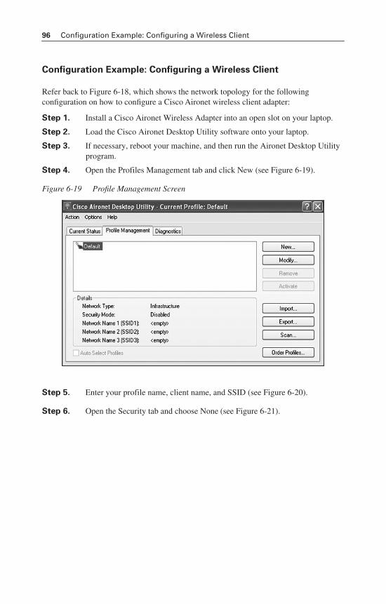
96 Configuration Example: Configuring a Wireless Client
Configuration Example: Configuring a Wireless Client
Refer back to Figure 6-18, which shows the network topology for the following configuration on how to configure a Cisco Aironet wireless client adapter:
Step 1. Install a Cisco Aironet Wireless Adapter into an open slot on your laptop.
Step 2. Load the Cisco Aironet Desktop Utility software onto your laptop.
Step 3. If necessary, reboot your machine, and then run the Aironet Desktop Utility program.
Step 4. Open the Profiles Management tab and click New (see Figure 6-19).
Figure 6-19 Profile Management Screen
Step 5. Enter your profile name, client name, and SSID (see Figure 6-20).
Step 6. Open the Security tab and choose None (see Figure 6-21).
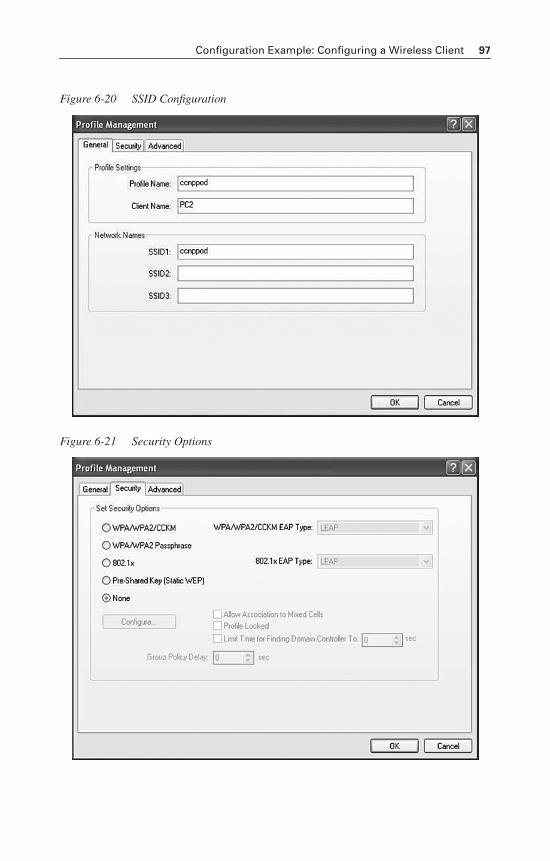
Configuration Example: Configuring a Wireless Client 97
Figure 6-20 SSID Configuration
Figure 6-21 Security Options
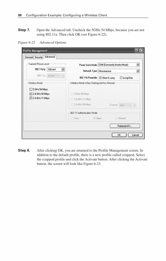
98 Configuration Example: Configuring a Wireless Client
Step 7. Open the Advanced tab. Uncheck the 5GHz 54 Mbps, because you are not using 802.11a. Then click OK (see Figure 6-22).
Figure 6-22 Advanced Options
Step 8. After clicking OK, you are returned to the Profile Management screen. In addition to the default profile, there is a new profile called ccnppod. Select the ccnppod profile and click the Activate button. After clicking the Activatebutton, the screen will look like Figure 6-23.
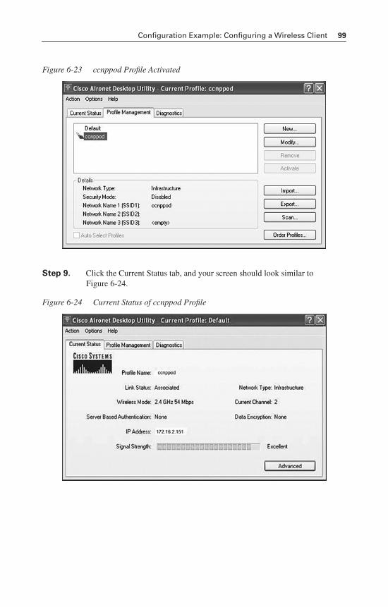
Configuration Example: Configuring a Wireless Client 99
Figure 6-23 ccnppod Profile Activated
Step 9. Click the Current Status tab, and your screen should look similar to Figure 6-24.
Figure 6-24 Current Status of ccnppod Profile

This page intentionally left blank
CHAPTER 7
Minimizing ServiceLoss and Data Theft
This chapter provides information and commands concerning the following topics:
• Configuring static MAC addresses
• Switch port security
• Verifying switch port security
• Sticky MAC addresses
• Mitigating VLAN hopping: best practices
• Configuring private VLANs (PVLAN)
• Verifying PVLANs
• Configuring protected ports
• VLAN access maps
• Verifying VLAN access maps
• DHCP snooping
• Verifying DHCP snooping
• Dynamic ARP Inspection (DAI)
• Verifying DAI
• 802.1x port-based authentication
• Cisco Discovery Protocol (CDP) security issues
• Configuring the Secure Shell (SSH) protocol
• vty access control lists (ACL)
• Restricting web interface sessions with ACLs
• Disabling unneeded services
• Securing end-device access ports
Configuring Static MAC Addresses
You can define the forwarding behavior of a switch port by adding a static MAC address to your configuration. This MAC address can be either a unicast or a multicast address, and the entry does not age and is retained when the switch restarts.
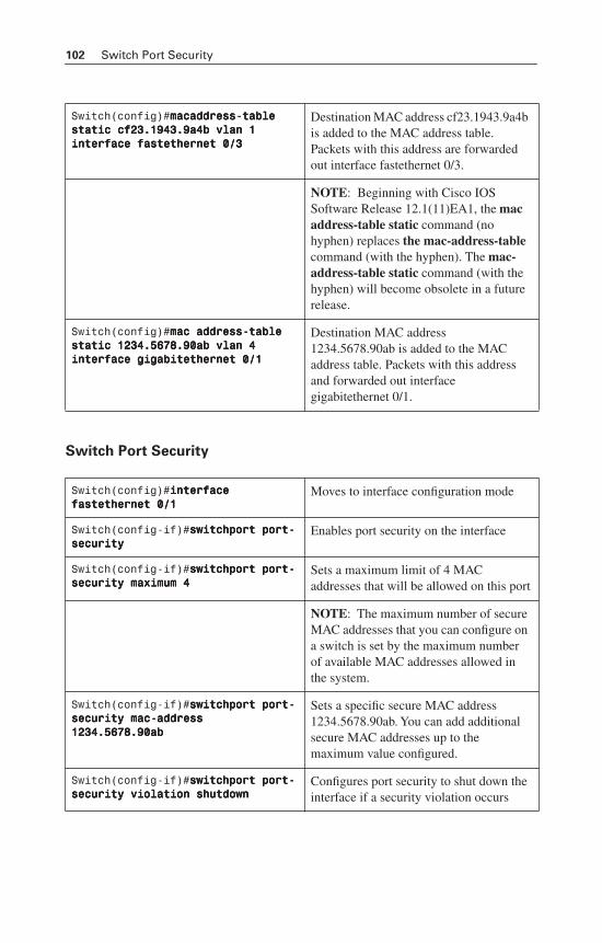
102 Switch Port Security
Switch Port Security
Switch(config)#mmmmaaaaccccaaaaddddddddrrrreeeessssssss----ttttaaaabbbblllleeee ssssttttaaaattttiiiicccc ccccffff22223333....1111999944443333....9999aaaa4444bbbb vvvvllllaaaannnn 1111 iiiinnnntttteeeerrrrffffaaaacccceeee ffffaaaasssstttteeeetttthhhheeeerrrrnnnneeeetttt 0000////3333
Destination MAC address cf23.1943.9a4b is added to the MAC address table. Packets with this address are forwarded out interface fastethernet 0/3.
NOTE: Beginning with Cisco IOS Software Release 12.1(11)EA1, the macaddress-table static command (no hyphen) replaces the mac-address-tablecommand (with the hyphen). The mac-address-table static command (with the hyphen) will become obsolete in a future release.
Switch(config)#mmmmaaaacccc aaaaddddddddrrrreeeessssssss----ttttaaaabbbblllleeee ssssttttaaaattttiiiicccc 1111222233334444....5555666677778888....99990000aaaabbbb vvvvllllaaaannnn 4444 iiiinnnntttteeeerrrrffffaaaacccceeee ggggiiiiggggaaaabbbbiiiitttteeeetttthhhheeeerrrrnnnneeeetttt 0000////1111
Destination MAC address 1234.5678.90ab is added to the MAC address table. Packets with this address and forwarded out interface gigabitethernet 0/1.
Switch(config)#iiiinnnntttteeeerrrrffffaaaacccceeee ffffaaaasssstttteeeetttthhhheeeerrrrnnnneeeetttt 0000////1111
Moves to interface configuration mode
Switch(config-if)#sssswwwwiiiittttcccchhhhppppoooorrrrtttt ppppoooorrrrtttt----sssseeeeccccuuuurrrriiiittttyyyy
Enables port security on the interface
Switch(config-if)#sssswwwwiiiittttcccchhhhppppoooorrrrtttt ppppoooorrrrtttt----sssseeeeccccuuuurrrriiiittttyyyy mmmmaaaaxxxxiiiimmmmuuuummmm 4444
Sets a maximum limit of 4 MAC addresses that will be allowed on this port
NOTE: The maximum number of secure MAC addresses that you can configure on a switch is set by the maximum number of available MAC addresses allowed in the system.
Switch(config-if)#sssswwwwiiiittttcccchhhhppppoooorrrrtttt ppppoooorrrrtttt----sssseeeeccccuuuurrrriiiittttyyyy mmmmaaaacccc----aaaaddddddddrrrreeeessssssss 1111222233334444....5555666677778888....99990000aaaabbbb
Sets a specific secure MAC address 1234.5678.90ab. You can add additional secure MAC addresses up to the maximum value configured.
Switch(config-if)#sssswwwwiiiittttcccchhhhppppoooorrrrtttt ppppoooorrrrtttt----sssseeeeccccuuuurrrriiiittttyyyy vvvviiiioooollllaaaattttiiiioooonnnn sssshhhhuuuuttttddddoooowwwwnnnn
Configures port security to shut down the interface if a security violation occurs
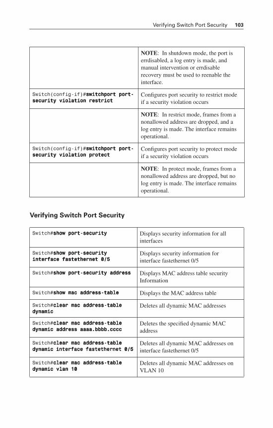
Verifying Switch Port Security 103
Verifying Switch Port Security
NOTE: In shutdown mode, the port is errdisabled, a log entry is made, and manual intervention or errdisable recovery must be used to reenable the interface.
Switch(config-if)#sssswwwwiiiittttcccchhhhppppoooorrrrtttt ppppoooorrrrtttt----sssseeeeccccuuuurrrriiiittttyyyy vvvviiiioooollllaaaattttiiiioooonnnn rrrreeeessssttttrrrriiiicccctttt
Configures port security to restrict mode if a security violation occurs
NOTE: In restrict mode, frames from a nonallowed address are dropped, and a log entry is made. The interface remains operational.
Switch(config-if)#sssswwwwiiiittttcccchhhhppppoooorrrrtttt ppppoooorrrrtttt----sssseeeeccccuuuurrrriiiittttyyyy vvvviiiioooollllaaaattttiiiioooonnnn pppprrrrooootttteeeecccctttt
Configures port security to protect mode if a security violation occurs
NOTE: In protect mode, frames from a nonallowed address are dropped, but no log entry is made. The interface remains operational.
Switch#sssshhhhoooowwww ppppoooorrrrtttt----sssseeeeccccuuuurrrriiiittttyyyy Displays security information for all interfaces
Switch#sssshhhhoooowwww ppppoooorrrrtttt----sssseeeeccccuuuurrrriiiittttyyyy iiiinnnntttteeeerrrrffffaaaacccceeee ffffaaaasssstttteeeetttthhhheeeerrrrnnnneeeetttt 0000////5555
Displays security information for interface fastethernet 0/5
Switch#sssshhhhoooowwww ppppoooorrrrtttt----sssseeeeccccuuuurrrriiiittttyyyy aaaaddddddddrrrreeeessssssss Displays MAC address table security Information
Switch#sssshhhhoooowwww mmmmaaaacccc aaaaddddddddrrrreeeessssssss----ttttaaaabbbblllleeee Displays the MAC address table
Switch#cccclllleeeeaaaarrrr mmmmaaaacccc aaaaddddddddrrrreeeessssssss----ttttaaaabbbblllleeee ddddyyyynnnnaaaammmmiiiicccc
Deletes all dynamic MAC addresses
Switch#cccclllleeeeaaaarrrr mmmmaaaacccc aaaaddddddddrrrreeeessssssss----ttttaaaabbbblllleeee ddddyyyynnnnaaaammmmiiiicccc aaaaddddddddrrrreeeessssssss aaaaaaaaaaaaaaaa....bbbbbbbbbbbbbbbb....cccccccccccccccc
Deletes the specified dynamic MAC address
Switch#cccclllleeeeaaaarrrr mmmmaaaacccc aaaaddddddddrrrreeeessssssss----ttttaaaabbbblllleeee ddddyyyynnnnaaaammmmiiiicccc iiiinnnntttteeeerrrrffffaaaacccceeee ffffaaaasssstttteeeetttthhhheeeerrrrnnnneeeetttt 0000////5555
Deletes all dynamic MAC addresses on interface fastethernet 0/5
Switch#cccclllleeeeaaaarrrr mmmmaaaacccc aaaaddddddddrrrreeeessssssss----ttttaaaabbbblllleeee ddddyyyynnnnaaaammmmiiiicccc vvvvllllaaaannnn 11110000
Deletes all dynamic MAC addresses on VLAN 10
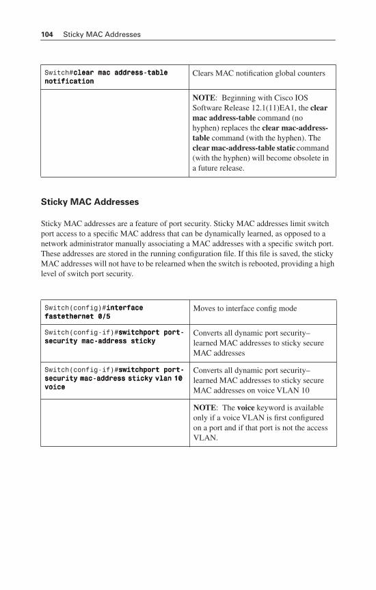
104 Sticky MAC Addresses
Sticky MAC Addresses
Sticky MAC addresses are a feature of port security. Sticky MAC addresses limit switch port access to a specific MAC address that can be dynamically learned, as opposed to a network administrator manually associating a MAC addresses with a specific switch port. These addresses are stored in the running configuration file. If this file is saved, the sticky MAC addresses will not have to be relearned when the switch is rebooted, providing a high level of switch port security.
Switch#cccclllleeeeaaaarrrr mmmmaaaacccc aaaaddddddddrrrreeeessssssss----ttttaaaabbbblllleeee nnnnoooottttiiiiffffiiiiccccaaaattttiiiioooonnnn
Clears MAC notification global counters
NOTE: Beginning with Cisco IOS Software Release 12.1(11)EA1, the clearmac address-table command (no hyphen) replaces the clear mac-address-table command (with the hyphen). The clear mac-address-table static command(with the hyphen) will become obsolete in a future release.
Switch(config)#iiiinnnntttteeeerrrrffffaaaacccceeee ffffaaaasssstttteeeetttthhhheeeerrrrnnnneeeetttt 0000////5555
Moves to interface config mode
Switch(config-if)#sssswwwwiiiittttcccchhhhppppoooorrrrtttt ppppoooorrrrtttt----sssseeeeccccuuuurrrriiiittttyyyy mmmmaaaacccc----aaaaddddddddrrrreeeessssssss ssssttttiiiicccckkkkyyyy
Converts all dynamic port security–learned MAC addresses to sticky secure MAC addresses
Switch(config-if)#sssswwwwiiiittttcccchhhhppppoooorrrrtttt ppppoooorrrrtttt----sssseeeeccccuuuurrrriiiittttyyyy mmmmaaaacccc----aaaaddddddddrrrreeeessssssss ssssttttiiiicccckkkkyyyy vvvvllllaaaannnn 11110000 vvvvooooiiiicccceeee
Converts all dynamic port security–learned MAC addresses to sticky secure MAC addresses on voice VLAN 10
NOTE: The voice keyword is available only if a voice VLAN is first configured on a port and if that port is not the access VLAN.
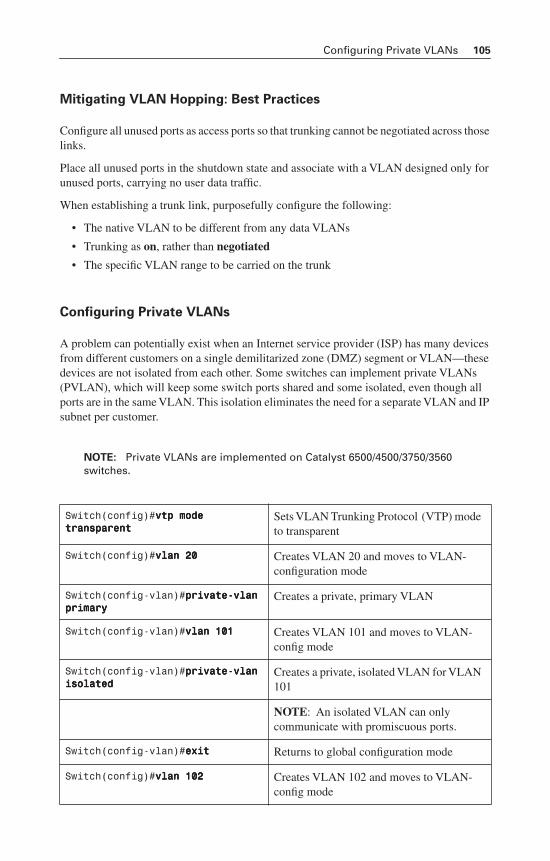
Configuring Private VLANs 105
Mitigating VLAN Hopping: Best Practices
Configure all unused ports as access ports so that trunking cannot be negotiated across those links.
Place all unused ports in the shutdown state and associate with a VLAN designed only for unused ports, carrying no user data traffic.
When establishing a trunk link, purposefully configure the following:
• The native VLAN to be different from any data VLANs
• Trunking as on, rather than negotiated
• The specific VLAN range to be carried on the trunk
Configuring Private VLANs
A problem can potentially exist when an Internet service provider (ISP) has many devices from different customers on a single demilitarized zone (DMZ) segment or VLAN—these devices are not isolated from each other. Some switches can implement private VLANs (PVLAN), which will keep some switch ports shared and some isolated, even though all ports are in the same VLAN. This isolation eliminates the need for a separate VLAN and IP subnet per customer.
NOTE: Private VLANs are implemented on Catalyst 6500/4500/3750/3560 switches.
Switch(config)#vvvvttttpppp mmmmooooddddeeee ttttrrrraaaannnnssssppppaaaarrrreeeennnntttt
Sets VLAN Trunking Protocol (VTP) mode to transparent
Switch(config)#vvvvllllaaaannnn 22220000 Creates VLAN 20 and moves to VLAN-configuration mode
Switch(config-vlan)#pppprrrriiiivvvvaaaatttteeee----vvvvllllaaaannnn pppprrrriiiimmmmaaaarrrryyyy
Creates a private, primary VLAN
Switch(config-vlan)#vvvvllllaaaannnn 111100001111 Creates VLAN 101 and moves to VLAN-config mode
Switch(config-vlan)#pppprrrriiiivvvvaaaatttteeee----vvvvllllaaaannnn iiiissssoooollllaaaatttteeeedddd
Creates a private, isolated VLAN for VLAN 101
NOTE: An isolated VLAN can only communicate with promiscuous ports.
Switch(config-vlan)#eeeexxxxiiiitttt Returns to global configuration mode
Switch(config)#vvvvllllaaaannnn 111100002222 Creates VLAN 102 and moves to VLAN-config mode
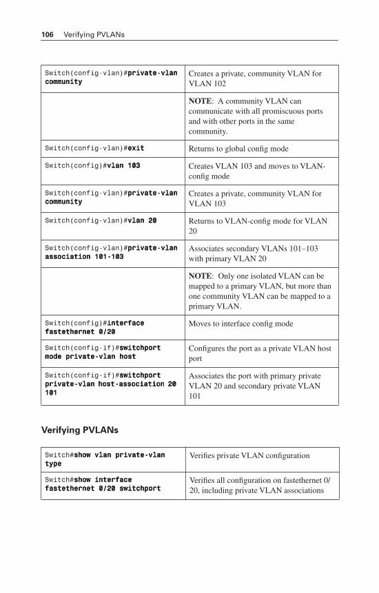
106 Verifying PVLANs
Verifying PVLANs
Switch(config-vlan)#pppprrrriiiivvvvaaaatttteeee----vvvvllllaaaannnn ccccoooommmmmmmmuuuunnnniiiittttyyyy
Creates a private, community VLAN for VLAN 102
NOTE: A community VLAN can communicate with all promiscuous ports and with other ports in the same community.
Switch(config-vlan)#eeeexxxxiiiitttt Returns to global config mode
Switch(config)#vvvvllllaaaannnn 111100003333 Creates VLAN 103 and moves to VLAN-config mode
Switch(config-vlan)#pppprrrriiiivvvvaaaatttteeee----vvvvllllaaaannnn ccccoooommmmmmmmuuuunnnniiiittttyyyy
Creates a private, community VLAN for VLAN 103
Switch(config-vlan)#vvvvllllaaaannnn 22220000 Returns to VLAN-config mode for VLAN 20
Switch(config-vlan)#pppprrrriiiivvvvaaaatttteeee----vvvvllllaaaannnn aaaassssssssoooocccciiiiaaaattttiiiioooonnnn 111100001111----111100003333
Associates secondary VLANs 101–103 with primary VLAN 20
NOTE: Only one isolated VLAN can be mapped to a primary VLAN, but more than one community VLAN can be mapped to a primary VLAN.
Switch(config)#iiiinnnntttteeeerrrrffffaaaacccceeee ffffaaaasssstttteeeetttthhhheeeerrrrnnnneeeetttt 0000////22220000
Moves to interface config mode
Switch(config-if)#sssswwwwiiiittttcccchhhhppppoooorrrrtttt mmmmooooddddeeee pppprrrriiiivvvvaaaatttteeee----vvvvllllaaaannnn hhhhoooosssstttt
Configures the port as a private VLAN host port
Switch(config-if)#sssswwwwiiiittttcccchhhhppppoooorrrrtttt pppprrrriiiivvvvaaaatttteeee----vvvvllllaaaannnn hhhhoooosssstttt----aaaassssssssoooocccciiiiaaaattttiiiioooonnnn 22220000 111100001111
Associates the port with primary private VLAN 20 and secondary private VLAN 101
Switch#sssshhhhoooowwww vvvvllllaaaannnn pppprrrriiiivvvvaaaatttteeee----vvvvllllaaaannnn ttttyyyyppppeeee
Verifies private VLAN configuration
Switch#sssshhhhoooowwww iiiinnnntttteeeerrrrffffaaaacccceeee ffffaaaasssstttteeeetttthhhheeeerrrrnnnneeeetttt 0000////22220000 sssswwwwiiiittttcccchhhhppppoooorrrrtttt
Verifies all configuration on fastethernet 0/20, including private VLAN associations
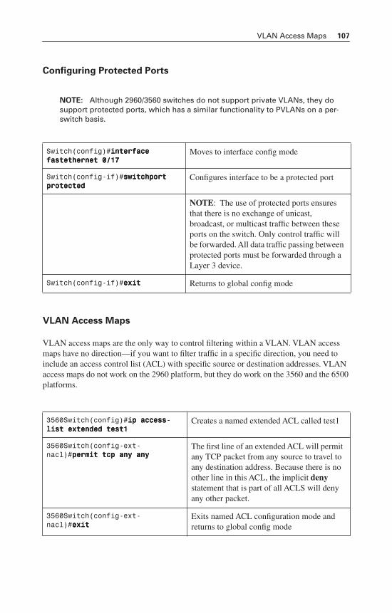
VLAN Access Maps 107
Configuring Protected Ports
NOTE: Although 2960/3560 switches do not support private VLANs, they do support protected ports, which has a similar functionality to PVLANs on a per-switch basis.
VLAN Access Maps
VLAN access maps are the only way to control filtering within a VLAN. VLAN access maps have no direction—if you want to filter traffic in a specific direction, you need to include an access control list (ACL) with specific source or destination addresses. VLAN access maps do not work on the 2960 platform, but they do work on the 3560 and the 6500 platforms.
Switch(config)#iiiinnnntttteeeerrrrffffaaaacccceeee ffffaaaasssstttteeeetttthhhheeeerrrrnnnneeeetttt 0000////11117777
Moves to interface config mode
Switch(config-if)#sssswwwwiiiittttcccchhhhppppoooorrrrtttt pppprrrrooootttteeeecccctttteeeedddd
Configures interface to be a protected port
NOTE: The use of protected ports ensures that there is no exchange of unicast, broadcast, or multicast traffic between these ports on the switch. Only control traffic will be forwarded. All data traffic passing between protected ports must be forwarded through a Layer 3 device.
Switch(config-if)#eeeexxxxiiiitttt Returns to global config mode
3560Switch(config)#iiiipppp aaaacccccccceeeessssssss----lllliiiisssstttt eeeexxxxtttteeeennnnddddeeeedddd tttteeeesssstttt1111
Creates a named extended ACL called test1
3560Switch(config-ext-nacl)#ppppeeeerrrrmmmmiiiitttt ttttccccpppp aaaannnnyyyy aaaannnnyyyy
The first line of an extended ACL will permit any TCP packet from any source to travel to any destination address. Because there is no other line in this ACL, the implicit denystatement that is part of all ACLS will deny any other packet.
3560Switch(config-ext-nacl)#eeeexxxxiiiitttt
Exits named ACL configuration mode and returns to global config mode
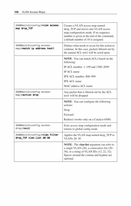
108 VLAN Access Maps
3560Switch(config)#vvvvllllaaaannnn aaaacccccccceeeessssssss----mmmmaaaapppp ddddrrrroooopppp____TTTTCCCCPPPP
Creates a VLAN access map named drop_TCP and moves into VLAN access map configuration mode. If no sequence number is given at the end of the command, a default number of 10 is assigned.
3560Switch(config-access-map)#mmmmaaaattttcccchhhh iiiipppp aaaaddddddddrrrreeeessssssss tttteeeesssstttt1111
Defines what needs to occur for this action to continue. In this case, packets filtered out by the named ACL test1 will be acted upon.
NOTE: You can match ACLs based on the following:
IP ACL number: 1–199 and 1300–2699
IP ACL name
IPX ACL number: 800–999
IPX ACL name
MAC address ACL name
3560Switch(config-access-map)#aaaaccccttttiiiioooonnnn ddddrrrroooopppp
Any packet that is filtered out by the ACL test1 will be dropped
NOTE: You can configure the following actions:
Drop
Forward
Redirect (works only on a Catalyst 6500)
3560Switch(config-access-drop)#eeeexxxxiiiitttt
Exits access map configuration mode and returns to global config mode
3560Switch(config)#vvvvllllaaaannnn ffffiiiilllltttteeeerrrr ddddrrrroooopppp____TTTTCCCCPPPP vvvvllllaaaannnn----lllliiiisssstttt 22220000----33330000
Applies the VLAN map named drop_TCP to VLANs 20–30
NOTE: The vlan-list argument can refer to a single VLAN (26), a consecutive list (20–30), or a string of VLAN IDs (12, 22, 32). Spaces around the comma and hyphen are optional.
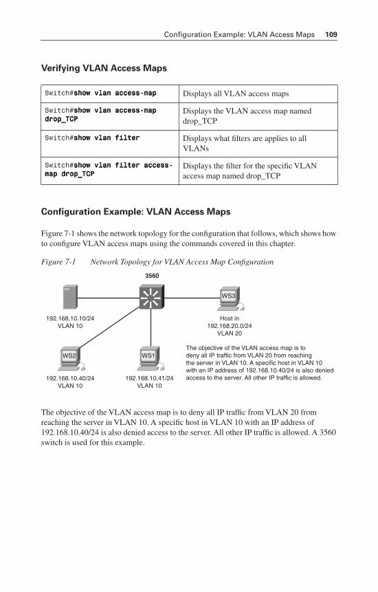
Configuration Example: VLAN Access Maps 109
Verifying VLAN Access Maps
Configuration Example: VLAN Access Maps
Figure 7-1 shows the network topology for the configuration that follows, which shows how to configure VLAN access maps using the commands covered in this chapter.
Figure 7-1 Network Topology for VLAN Access Map Configuration
The objective of the VLAN access map is to deny all IP traffic from VLAN 20 from reaching the server in VLAN 10. A specific host in VLAN 10 with an IP address of 192.168.10.40/24 is also denied access to the server. All other IP traffic is allowed. A 3560 switch is used for this example.
Switch#sssshhhhoooowwww vvvvllllaaaannnn aaaacccccccceeeessssssss----mmmmaaaapppp Displays all VLAN access maps
Switch#sssshhhhoooowwww vvvvllllaaaannnn aaaacccccccceeeessssssss----mmmmaaaapppp ddddrrrroooopppp____TTTTCCCCPPPP
Displays the VLAN access map named drop_TCP
Switch#sssshhhhoooowwww vvvvllllaaaannnn ffffiiiilllltttteeeerrrr Displays what filters are applies to all VLANs
Switch#sssshhhhoooowwww vvvvllllaaaannnn ffffiiiilllltttteeeerrrr aaaacccccccceeeessssssss----mmmmaaaapppp ddddrrrroooopppp____TTTTCCCCPPPP
Displays the filter for the specific VLAN access map named drop_TCP
192.168.10.10/24VLAN 10
Host in192.168.20.0/24
VLAN 20
WS3
3560
192.168.10.41/24VLAN 10
The objective of the VLAN access map is todeny all IP traffic from VLAN 20 from reachingthe server in VLAN 10. A specific host in VLAN 10with an IP address of 192.168.10.40/24 is also deniedaccess to the server. All other IP traffic is allowed.
WS1
192.168.10.40/24VLAN 10
WS2
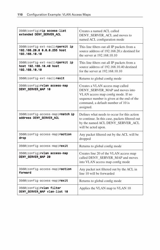
110 Configuration Example: VLAN Access Maps
3560(config)#iiiipppp aaaacccccccceeeessssssss----lllliiiisssstttt eeeexxxxtttteeeennnnddddeeeedddd DDDDEEEENNNNYYYY____SSSSEEEERRRRVVVVEEEERRRR____AAAACCCCLLLL
Creates a named ACL called DENY_SERVER_ACL and moves to named ACL configuration mode
3560(config-ext-nacl)#ppppeeeerrrrmmmmiiiitttt iiiipppp 111199992222....111166668888....22220000....0000 0000....0000....0000....222255555555 hhhhoooosssstttt 111199992222....111166668888....11110000....11110000
This line filters out all IP packets from a source address of 192.168.20.x destined for the server at 192.168.10.10
3560(config-ext-nacl)#ppppeeeerrrrmmmmiiiitttt iiiipppp hhhhoooosssstttt 111199992222....111166668888....11110000....44440000 hhhhoooosssstttt 111199992222....111166668888....11110000....11110000
This line filters out all IP packets from a source address of 192.168.10.40 destined for the server at 192.168.10.10
3560(config-ext-nacl)#eeeexxxxiiiitttt Returns to global config mode
3560(config)#vvvvllllaaaannnn aaaacccccccceeeessssssss----mmmmaaaapppp DDDDEEEENNNNYYYY____SSSSEEEERRRRVVVVEEEERRRR____MMMMAAAAPPPP 11110000
Creates a VLAN access map called DENY_SERVER_MAP and moves into VLAN access map config mode. If no sequence number is given at the end of the command, a default number of 10 is assigned.
3560(config-access-map)#mmmmaaaattttcccchhhh iiiipppp aaaaddddddddrrrreeeessssssss DDDDEEEENNNNYYYY____SSSSEEEERRRRVVVVEEEERRRR____AAAACCCCLLLL
Defines what needs to occur for this action to continue. In this case, packets filtered out by the named ACL DENY_SERVER_ACLwill be acted upon.
3560(config-access-map)#aaaaccccttttiiiioooonnnn ddddrrrroooopppp
Any packet filtered out by the ACL will be dropped
3560(config-access-map)#eeeexxxxiiiitttt Returns to global config mode
3560(config)#vvvvllllaaaannnn aaaacccccccceeeessssssss----mmmmaaaapppp DDDDEEEENNNNYYYY____SSSSEEEERRRRVVVVEEEERRRR____MMMMAAAAPPPP 22220000
Creates line 20 of the VLAN access map called DENY_SERVER_MAP and moves into VLAN access map config mode
3560(config-access-map)#aaaaccccttttiiiioooonnnn ffffoooorrrrwwwwaaaarrrrdddd
Any packet not filtered out by the ACL in line 10 will be forwarded
3560(config-access-map)#eeeexxxxiiiitttt Returns to global config mode
3560(config)#vvvvllllaaaannnn ffffiiiilllltttteeeerrrr DDDDEEEENNNNYYYY____SSSSEEEERRRRVVVVEEEERRRR____MMMMAAAAPPPP vvvvllllaaaannnn----lllliiiisssstttt 11110000
Applies the VLAN map to VLAN 10
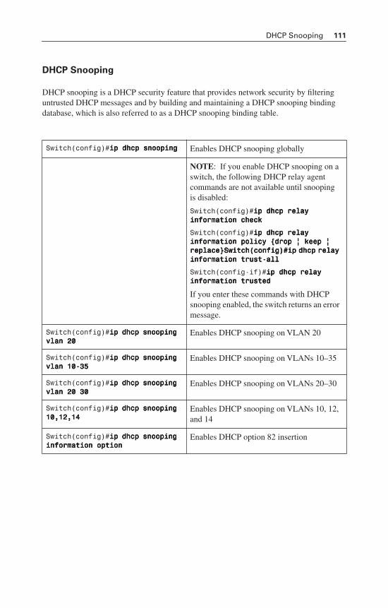
DHCP Snooping 111
DHCP Snooping
DHCP snooping is a DHCP security feature that provides network security by filtering untrusted DHCP messages and by building and maintaining a DHCP snooping binding database, which is also referred to as a DHCP snooping binding table.
Switch(config)#iiiipppp ddddhhhhccccpppp ssssnnnnooooooooppppiiiinnnngggg Enables DHCP snooping globally
NOTE: If you enable DHCP snooping on a switch, the following DHCP relay agent commands are not available until snooping is disabled:
Switch(config)#iiiipppp ddddhhhhccccpppp rrrreeeellllaaaayyyy iiiinnnnffffoooorrrrmmmmaaaattttiiiioooonnnn cccchhhheeeecccckkkk
Switch(config)#iiiipppp ddddhhhhccccpppp rrrreeeellllaaaayyyy iiiinnnnffffoooorrrrmmmmaaaattttiiiioooonnnn ppppoooolllliiiiccccyyyy {{{{ddddrrrroooopppp |||| kkkkeeeeeeeepppp |||| rrrreeeeppppllllaaaacccceeee}}}}SSSSwwwwiiiittttcccchhhh((((ccccoooonnnnffffiiiigggg))))####iiiipppp ddddhhhhccccpppp rrrreeeellllaaaayyyy iiiinnnnffffoooorrrrmmmmaaaattttiiiioooonnnn ttttrrrruuuusssstttt----aaaallllllll
Switch(config-if)#iiiipppp ddddhhhhccccpppp rrrreeeellllaaaayyyy iiiinnnnffffoooorrrrmmmmaaaattttiiiioooonnnn ttttrrrruuuusssstttteeeedddd
If you enter these commands with DHCP snooping enabled, the switch returns an error message.
Switch(config)#iiiipppp ddddhhhhccccpppp ssssnnnnooooooooppppiiiinnnngggg vvvvllllaaaannnn 22220000
Enables DHCP snooping on VLAN 20
Switch(config)#iiiipppp ddddhhhhccccpppp ssssnnnnooooooooppppiiiinnnngggg vvvvllllaaaannnn 11110000----33335555
Enables DHCP snooping on VLANs 10–35
Switch(config)#iiiipppp ddddhhhhccccpppp ssssnnnnooooooooppppiiiinnnngggg vvvvllllaaaannnn 22220000 33330000
Enables DHCP snooping on VLANs 20–30
Switch(config)#iiiipppp ddddhhhhccccpppp ssssnnnnooooooooppppiiiinnnngggg 11110000,,,,11112222,,,,11114444
Enables DHCP snooping on VLANs 10, 12, and 14
Switch(config)#iiiipppp ddddhhhhccccpppp ssssnnnnooooooooppppiiiinnnngggg iiiinnnnffffoooorrrrmmmmaaaattttiiiioooonnnn ooooppppttttiiiioooonnnn
Enables DHCP option 82 insertion
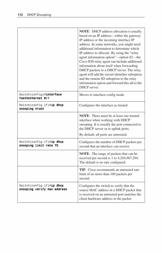
112 DHCP Snooping
NOTE: DHCP address allocation is usually based on an IP address—either the gateway IP address or the incoming interface IP address. In some networks, you might need additional information to determine which IP address to allocate. By using the “relay agent information option”—option 82—the Cisco IOS relay agent can include additional information about itself when forwarding DHCP packets to a DHCP server. The relay agent will add the circuit identifier suboption and the remote ID suboption to the relay information option and forward this all to the DHCP server.
Switch(config)#iiiinnnntttteeeerrrrffffaaaacccceeee ffffaaaasssstttthhhheeeetttthhhheeeerrrrnnnneeeetttt 0000////1111
Moves to interface config mode
Switch(config-if)#iiiipppp ddddhhhhccccpppp ssssnnnnooooooooppppiiiinnnngggg ttttrrrruuuusssstttt
Configures the interface as trusted
NOTE: There must be at least one trusted interface when working with DHCP snooping. It is usually the port connected to the DHCP server or to uplink ports.
By default, all ports are untrusted.
Switch(config-if)#iiiipppp ddddhhhhccccpppp ssssnnnnooooooooppppiiiinnnngggg lllliiiimmmmiiiitttt rrrraaaatttteeee 77775555
Configures the number of DHCP packets per second that an interface can receive
NOTE: The range of packets that can be received per second is 1 to 4,294,967,294. The default is no rate configured.
TIP: Cisco recommends an untrusted rate limit of no more than 100 packets per second.
Switch(config-if)#iiiipppp ddddhhhhccccpppp ssssnnnnooooooooppppiiiinnnngggg vvvveeeerrrriiiiffffyyyy mmmmaaaacccc----aaaaddddddddrrrreeeessssssss
Configures the switch to verify that the source MAC address in a DHCP packet that is received on an untrusted port matches the client hardware address in the packet
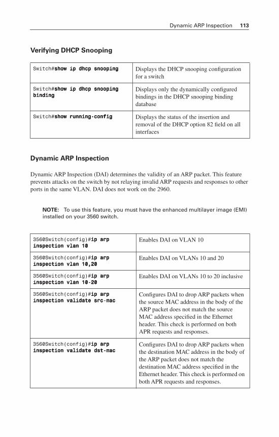
Dynamic ARP Inspection 113
Verifying DHCP Snooping
Dynamic ARP Inspection
Dynamic ARP Inspection (DAI) determines the validity of an ARP packet. This feature prevents attacks on the switch by not relaying invalid ARP requests and responses to other ports in the same VLAN. DAI does not work on the 2960.
NOTE: To use this feature, you must have the enhanced multilayer image (EMI) installed on your 3560 switch.
Switch#sssshhhhoooowwww iiiipppp ddddhhhhccccpppp ssssnnnnooooooooppppiiiinnnngggg Displays the DHCP snooping configuration for a switch
Switch#sssshhhhoooowwww iiiipppp ddddhhhhccccpppp ssssnnnnooooooooppppiiiinnnngggg bbbbiiiinnnnddddiiiinnnngggg
Displays only the dynamically configured bindings in the DHCP snooping binding database
Switch#sssshhhhoooowwww rrrruuuunnnnnnnniiiinnnngggg----ccccoooonnnnffffiiiigggg Displays the status of the insertion and removal of the DHCP option 82 field on all interfaces
3560Switch(config)#iiiipppp aaaarrrrpppp iiiinnnnssssppppeeeeccccttttiiiioooonnnn vvvvllllaaaannnn 11110000
Enables DAI on VLAN 10
3560Switch(config)#iiiipppp aaaarrrrpppp iiiinnnnssssppppeeeeccccttttiiiioooonnnn vvvvllllaaaannnn 11110000,,,,22220000
Enables DAI on VLANs 10 and 20
3560Switch(config)#iiiipppp aaaarrrrpppp iiiinnnnssssppppeeeeccccttttiiiioooonnnn vvvvllllaaaannnn 11110000----22220000
Enables DAI on VLANs 10 to 20 inclusive
3560Switch(config)#iiiipppp aaaarrrrpppp iiiinnnnssssppppeeeeccccttttiiiioooonnnn vvvvaaaalllliiiiddddaaaatttteeee ssssrrrrcccc----mmmmaaaacccc
Configures DAI to drop ARP packets when the source MAC address in the body of the ARP packet does not match the source MAC address specified in the Ethernet header. This check is performed on both APR requests and responses.
3560Switch(config)#iiiipppp aaaarrrrpppp iiiinnnnssssppppeeeeccccttttiiiioooonnnn vvvvaaaalllliiiiddddaaaatttteeee ddddsssstttt----mmmmaaaacccc
Configures DAI to drop ARP packets when the destination MAC address in the body of the ARP packet does not match the destination MAC address specified in the Ethernet header. This check is performed on both APR requests and responses.
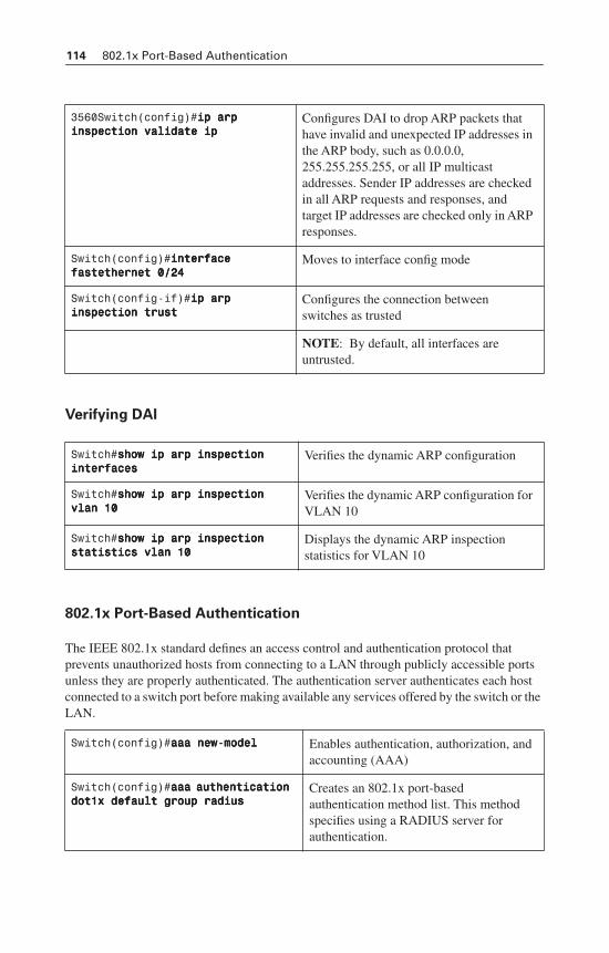
114 802.1x Port-Based Authentication
Verifying DAI
802.1x Port-Based Authentication
The IEEE 802.1x standard defines an access control and authentication protocol that prevents unauthorized hosts from connecting to a LAN through publicly accessible ports unless they are properly authenticated. The authentication server authenticates each host connected to a switch port before making available any services offered by the switch or the LAN.
3560Switch(config)#iiiipppp aaaarrrrpppp iiiinnnnssssppppeeeeccccttttiiiioooonnnn vvvvaaaalllliiiiddddaaaatttteeee iiiipppp
Configures DAI to drop ARP packets that have invalid and unexpected IP addresses in the ARP body, such as 0.0.0.0, 255.255.255.255, or all IP multicast addresses. Sender IP addresses are checked in all ARP requests and responses, and target IP addresses are checked only in ARP responses.
Switch(config)#iiiinnnntttteeeerrrrffffaaaacccceeee ffffaaaasssstttteeeetttthhhheeeerrrrnnnneeeetttt 0000////22224444
Moves to interface config mode
Switch(config-if)#iiiipppp aaaarrrrpppp iiiinnnnssssppppeeeeccccttttiiiioooonnnn ttttrrrruuuusssstttt
Configures the connection between switches as trusted
NOTE: By default, all interfaces are untrusted.
Switch#sssshhhhoooowwww iiiipppp aaaarrrrpppp iiiinnnnssssppppeeeeccccttttiiiioooonnnn iiiinnnntttteeeerrrrffffaaaacccceeeessss
Verifies the dynamic ARP configuration
Switch#sssshhhhoooowwww iiiipppp aaaarrrrpppp iiiinnnnssssppppeeeeccccttttiiiioooonnnn vvvvllllaaaannnn 11110000
Verifies the dynamic ARP configuration for VLAN 10
Switch#sssshhhhoooowwww iiiipppp aaaarrrrpppp iiiinnnnssssppppeeeeccccttttiiiioooonnnn ssssttttaaaattttiiiissssttttiiiiccccssss vvvvllllaaaannnn 11110000
Displays the dynamic ARP inspection statistics for VLAN 10
Switch(config)#aaaaaaaaaaaa nnnneeeewwww----mmmmooooddddeeeellll Enables authentication, authorization, and accounting (AAA)
Switch(config)#aaaaaaaaaaaa aaaauuuutttthhhheeeennnnttttiiiiccccaaaattttiiiioooonnnn ddddooootttt1111xxxx ddddeeeeffffaaaauuuulllltttt ggggrrrroooouuuupppp rrrraaaaddddiiiiuuuussss
Creates an 802.1x port-based authentication method list. This method specifies using a RADIUS server for authentication.
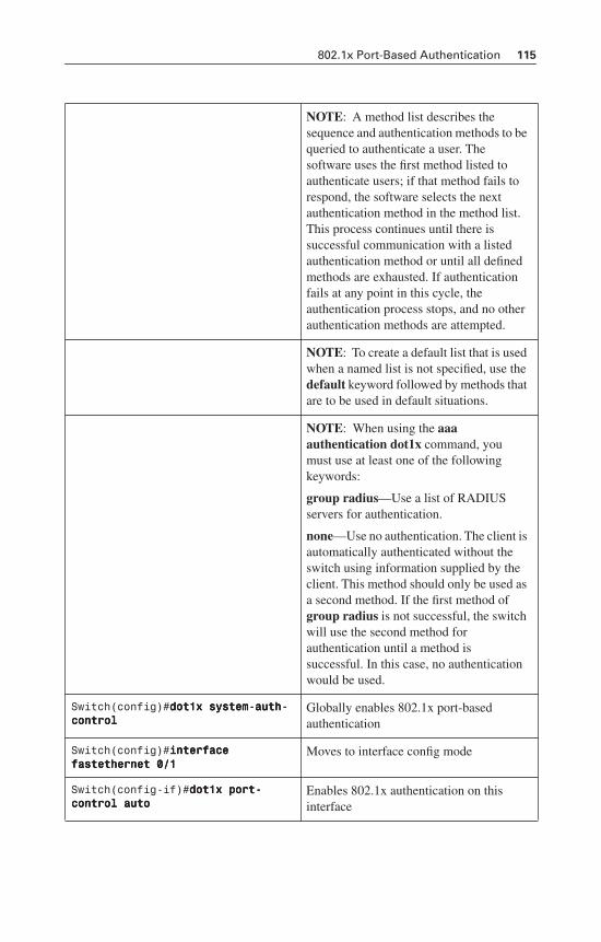
802.1x Port-Based Authentication 115
NOTE: A method list describes the sequence and authentication methods to be queried to authenticate a user. The software uses the first method listed to authenticate users; if that method fails to respond, the software selects the next authentication method in the method list. This process continues until there is successful communication with a listed authentication method or until all defined methods are exhausted. If authentication fails at any point in this cycle, the authentication process stops, and no other authentication methods are attempted.
NOTE: To create a default list that is used when a named list is not specified, use the default keyword followed by methods that are to be used in default situations.
NOTE: When using the aaaauthentication dot1x command, you must use at least one of the following keywords:
group radius—Use a list of RADIUS servers for authentication.
none—Use no authentication. The client is automatically authenticated without the switch using information supplied by the client. This method should only be used as a second method. If the first method of group radius is not successful, the switch will use the second method for authentication until a method is successful. In this case, no authentication would be used.
Switch(config)#ddddooootttt1111xxxx ssssyyyysssstttteeeemmmm----aaaauuuutttthhhh----ccccoooonnnnttttrrrroooollll
Globally enables 802.1x port-based authentication
Switch(config)#iiiinnnntttteeeerrrrffffaaaacccceeee ffffaaaasssstttteeeetttthhhheeeerrrrnnnneeeetttt 0000////1111
Moves to interface config mode
Switch(config-if)#ddddooootttt1111xxxx ppppoooorrrrtttt----ccccoooonnnnttttrrrroooollll aaaauuuuttttoooo
Enables 802.1x authentication on this interface
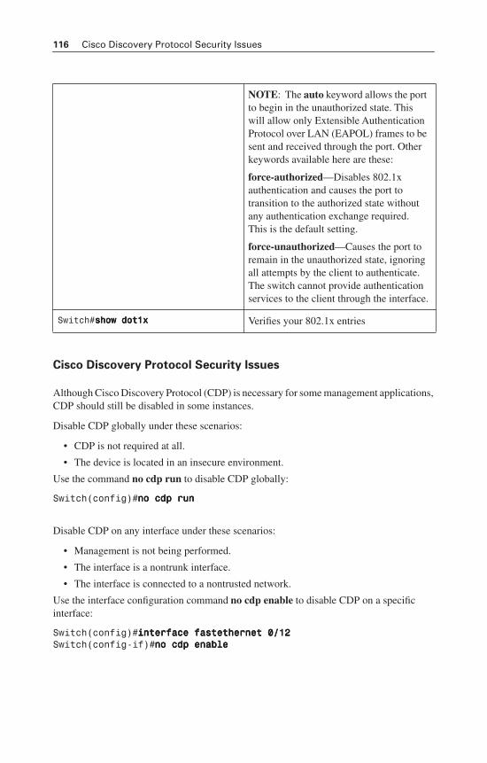
116 Cisco Discovery Protocol Security Issues
Cisco Discovery Protocol Security Issues
Although Cisco Discovery Protocol (CDP) is necessary for some management applications, CDP should still be disabled in some instances.
Disable CDP globally under these scenarios:
• CDP is not required at all.
• The device is located in an insecure environment.
Use the command no cdp run to disable CDP globally:
Switch(config)#nnnnoooo ccccddddpppp rrrruuuunnnn
Disable CDP on any interface under these scenarios:
• Management is not being performed.
• The interface is a nontrunk interface.
• The interface is connected to a nontrusted network.
Use the interface configuration command no cdp enable to disable CDP on a specific interface:
Switch(config)#iiiinnnntttteeeerrrrffffaaaacccceeee ffffaaaasssstttteeeetttthhhheeeerrrrnnnneeeetttt 0000////11112222Switch(config-if)#nnnnoooo ccccddddpppp eeeennnnaaaabbbblllleeee
NOTE: The auto keyword allows the port to begin in the unauthorized state. This will allow only Extensible Authentication Protocol over LAN (EAPOL) frames to be sent and received through the port. Other keywords available here are these:
force-authorized—Disables 802.1x authentication and causes the port to transition to the authorized state without any authentication exchange required. This is the default setting.
force-unauthorized—Causes the port to remain in the unauthorized state, ignoring all attempts by the client to authenticate. The switch cannot provide authentication services to the client through the interface.
Switch#sssshhhhoooowwww ddddooootttt1111xxxx Verifies your 802.1x entries
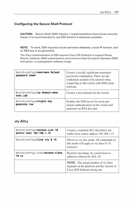
vty ACLs 117
Configuring the Secure Shell Protocol
CAUTION: Secure Shell (SSH) Version 1 implementations have known security issues. It is recommended to use SSH Version 2 whenever possible.
NOTE: To work, SSH requires a local username database, a local IP domain, and an RSA key to be generated.
The Cisco implementation of SSH requires Cisco IOS Software to support Rivest, Shamit, Adleman (RSA) authentication and minimum Data Encryption Standard (DES) encryption—a cryptographic software image.
vty ACLs
Switch(config)#uuuusssseeeerrrrnnnnaaaammmmeeee RRRRoooollllaaaannnndddd ppppaaaasssssssswwwwoooorrrrdddd ttttoooowwwweeeerrrr
Creates a locally significant username/password combination. These are the credentials needed to be entered when connecting to the switch with SSH client software.
Switch(config)#iiiipppp ddddoooommmmaaaaiiiinnnn----nnnnaaaammmmeeee tttteeeesssstttt....llllaaaabbbb
Creates a host domain for the switch
Switch(config)#ccccrrrryyyyppppttttoooo kkkkeeeeyyyy ggggeeeennnneeeerrrraaaatttteeee rrrrssssaaaa
Enables the SSH server for local and remote authentication on the switch and generates an RSA key pair
Switch(config)#aaaacccccccceeeessssssss----lllliiiisssstttt 11110000 ppppeeeerrrrmmmmiiiitttt hhhhoooosssstttt 111199992222....111166668888....1111....11115555
Creates a standard ACL that filters out traffic from source address 192.168.1.15
Switch(config)#lllliiiinnnneeee vvvvttttyyyy 0000 11115555 Moves to vty line mode. All commands in this mode will apply to vty lines 0–15 inclusive.
Switch(config-line)#aaaacccccccceeeessssssss----ccccllllaaaassssssss 11110000 iiiinnnn
Restricts incoming vty connections to addresses filtered by ACL 10
NOTE: The actual number of vty lines depends on the platform and the version of Cisco IOS Software being run.
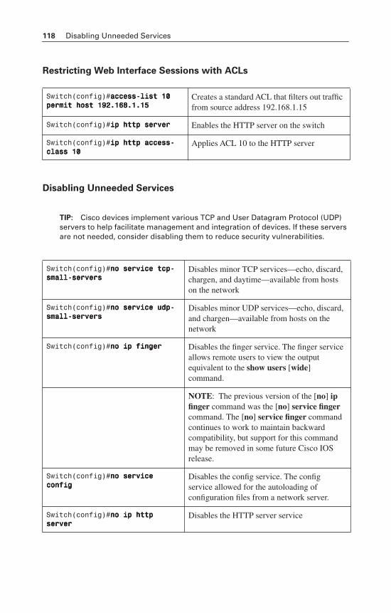
118 Disabling Unneeded Services
Restricting Web Interface Sessions with ACLs
Disabling Unneeded Services
TIP: Cisco devices implement various TCP and User Datagram Protocol (UDP) servers to help facilitate management and integration of devices. If these servers are not needed, consider disabling them to reduce security vulnerabilities.
Switch(config)#aaaacccccccceeeessssssss----lllliiiisssstttt 11110000 ppppeeeerrrrmmmmiiiitttt hhhhoooosssstttt 111199992222....111166668888....1111....11115555
Creates a standard ACL that filters out traffic from source address 192.168.1.15
Switch(config)#iiiipppp hhhhttttttttpppp sssseeeerrrrvvvveeeerrrr Enables the HTTP server on the switch
Switch(config)#iiiipppp hhhhttttttttpppp aaaacccccccceeeessssssss----ccccllllaaaassssssss 11110000
Applies ACL 10 to the HTTP server
Switch(config)#nnnnoooo sssseeeerrrrvvvviiiicccceeee ttttccccpppp----ssssmmmmaaaallllllll----sssseeeerrrrvvvveeeerrrrssss
Disables minor TCP services—echo, discard, chargen, and daytime—available from hosts on the network
Switch(config)#nnnnoooo sssseeeerrrrvvvviiiicccceeee uuuuddddpppp----ssssmmmmaaaallllllll----sssseeeerrrrvvvveeeerrrrssss
Disables minor UDP services—echo, discard, and chargen—available from hosts on the network
Switch(config)#nnnnoooo iiiipppp ffffiiiinnnnggggeeeerrrr Disables the finger service. The finger service allows remote users to view the output equivalent to the show users [wide]command.
NOTE: The previous version of the [no] ip finger command was the [no] service fingercommand. The [no] service finger command continues to work to maintain backward compatibility, but support for this command may be removed in some future Cisco IOS release.
Switch(config)#nnnnoooo sssseeeerrrrvvvviiiicccceeee ccccoooonnnnffffiiiigggg
Disables the config service. The config service allowed for the autoloading of configuration files from a network server.
Switch(config)#nnnnoooo iiiipppp hhhhttttttttpppp sssseeeerrrrvvvveeeerrrr
Disables the HTTP server service
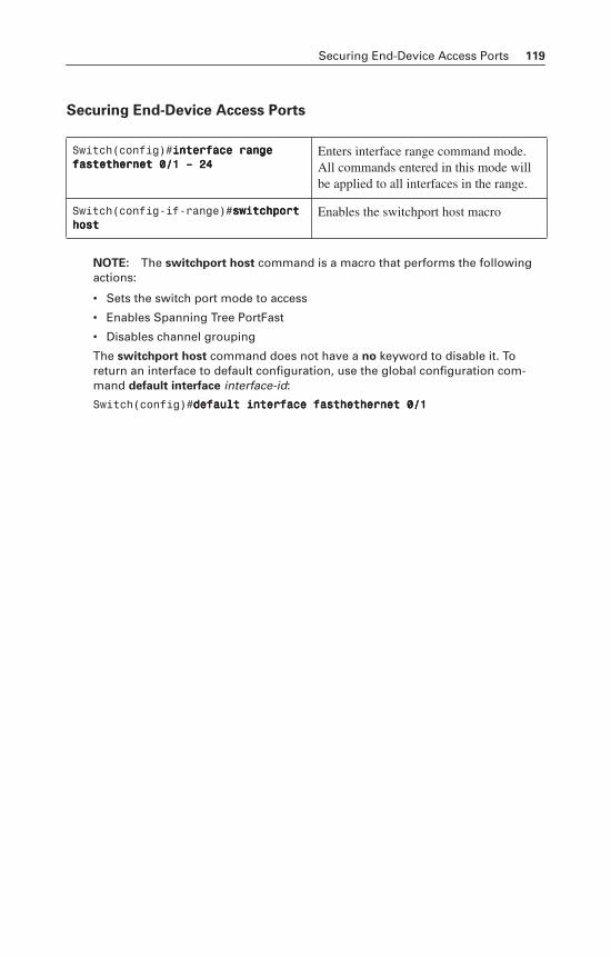
Securing End-Device Access Ports 119
Securing End-Device Access Ports
NOTE: The switchport host command is a macro that performs the following actions:
• Sets the switch port mode to access
• Enables Spanning Tree PortFast
• Disables channel grouping
The switchport host command does not have a no keyword to disable it. To return an interface to default configuration, use the global configuration com-mand default interface interface-id:
Switch(config)#ddddeeeeffffaaaauuuulllltttt iiiinnnntttteeeerrrrffffaaaacccceeee ffffaaaasssstttthhhheeeetttthhhheeeerrrrnnnneeeetttt 0000////1111
Switch(config)#iiiinnnntttteeeerrrrffffaaaacccceeee rrrraaaannnnggggeeee ffffaaaasssstttteeeetttthhhheeeerrrrnnnneeeetttt 0000////1111 –––– 22224444
Enters interface range command mode. All commands entered in this mode will be applied to all interfaces in the range.
Switch(config-if-range)#sssswwwwiiiittttcccchhhhppppoooorrrrtttt hhhhoooosssstttt
Enables the switchport host macro

This page intentionally left blank
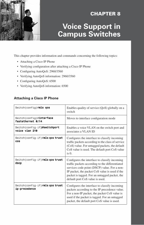
CHAPTER 8
Voice Support inCampus Switches
This chapter provides information and commands concerning the following topics:
• Attaching a Cisco IP Phone
• Verifying configuration after attaching a Cisco IP Phone
• Configuring AutoQoS: 2960/3560
• Verifying AutoQoS information: 2960/3560
• Configuring AutoQoS: 6500
• Verifying AutoQoS information: 6500
Attaching a Cisco IP Phone
Switch(config)#mmmmllllssss qqqqoooossss Enables quality of service (QoS) globally on a switch
Switch(config)#iiiinnnntttteeeerrrrffffaaaacccceeee ffffaaaasssstttteeeetttthhhheeeerrrrnnnneeeetttt 0000////11114444
Moves to interface configuration mode
Switch(config-if))))####sssswwwwiiiittttcccchhhhppppoooorrrrtttt vvvvooooiiiicccceeee vvvvllllaaaannnn 222211110000
Enables a voice VLAN on the switch port and associates a VLAN ID
Switch(config-if)#mmmmllllssss qqqqoooossss ttttrrrruuuusssstttt ccccoooossss
Configures the interface to classify incoming traffic packets according to the class of service (CoS) value. For untagged packets, the default CoS value is used. The default port CoS value is 0.
Switch(config-if)#mmmmllllssss qqqqoooossss ttttrrrruuuusssstttt ddddssssccccpppp
Configures the interface to classify incoming traffic packets according to the differentiated services code point (DSCP) value. For a non-IP packet, the packet CoS value is used if the packet is tagged. For an untagged packet, the default port CoS value is used.
Switch(config-if)#mmmmllllssss qqqqoooossss ttttrrrruuuusssstttt iiiipppp----pppprrrreeeecccceeeeddddeeeennnncccceeee
Configures the interface to classify incoming packets according to the IP precedence value. For a non-IP packet, the packet CoS value is used if the packet is tagged. For an untagged packet, the default port CoS value is used.
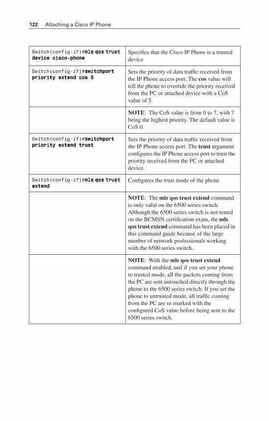
122 Attaching a Cisco IP Phone
Switch(config-if)#mmmmllllssss qqqqoooossss ttttrrrruuuusssstttt ddddeeeevvvviiiicccceeee cccciiiissssccccoooo----pppphhhhoooonnnneeee
Specifies that the Cisco IP Phone is a trusted device
Switch(config-if)#sssswwwwiiiittttcccchhhhppppoooorrrrtttt pppprrrriiiioooorrrriiiittttyyyy eeeexxxxtttteeeennnndddd ccccoooossss 5555
Sets the priority of data traffic received from the IP Phone access port. The cos value will tell the phone to override the priority received from the PC or attached device with a CoS value of 5.
NOTE: The CoS value is from 0 to 7, with 7 being the highest priority. The default value is CoS 0.
Switch(config-if)#sssswwwwiiiittttcccchhhhppppoooorrrrtttt pppprrrriiiioooorrrriiiittttyyyy eeeexxxxtttteeeennnndddd ttttrrrruuuusssstttt
Sets the priority of data traffic received from the IP Phone access port. The trust argument configures the IP Phone access port to trust the priority received from the PC or attached device.
Switch(config-if)#mmmmllllssss qqqqoooossss ttttrrrruuuusssstttt eeeexxxxtttteeeennnndddd
Configures the trust mode of the phone
NOTE: The mls qos trust extend command is only valid on the 6500 series switch. Although the 6500 series switch is not tested on the BCMSN certification exam, the mlsqos trust extend command has been placed in this command guide because of the large number of network professionals working with the 6500 series switch.
NOTE: With the mls qos trust extendcommand enabled, and if you set your phone to trusted mode, all the packets coming from the PC are sent untouched directly through the phone to the 6500 series switch. If you set the phone to untrusted mode, all traffic coming from the PC are re-marked with the configured CoS value before being sent to the 6500 series switch.
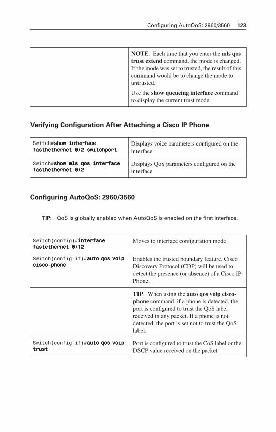
Configuring AutoQoS: 2960/3560 123
Verifying Configuration After Attaching a Cisco IP Phone
Configuring AutoQoS: 2960/3560
TIP: QoS is globally enabled when AutoQoS is enabled on the first interface.
NOTE: Each time that you enter the mls qos trust extend command, the mode is changed. If the mode was set to trusted, the result of this command would be to change the mode to untrusted.
Use the show queueing interface commandto display the current trust mode.
Switch#sssshhhhoooowwww iiiinnnntttteeeerrrrffffaaaacccceeee ffffaaaasssstttthhhheeeetttthhhheeeerrrrnnnneeeetttt 0000////2222 sssswwwwiiiittttcccchhhhppppoooorrrrtttt
Displays voice parameters configured on the interface
Switch#sssshhhhoooowwww mmmmllllssss qqqqoooossss iiiinnnntttteeeerrrrffffaaaacccceeee ffffaaaasssstttthhhheeeetttthhhheeeerrrrnnnneeeetttt 0000////2222
Displays QoS parameters configured on the interface
Switch(config)#iiiinnnntttteeeerrrrffffaaaacccceeee ffffaaaasssstttteeeetttthhhheeeerrrrnnnneeeetttt 0000////11112222
Moves to interface configuration mode
Switch(config-if)#aaaauuuuttttoooo qqqqoooossss vvvvooooiiiipppp cccciiiissssccccoooo----pppphhhhoooonnnneeee
Enables the trusted boundary feature. Cisco Discovery Protocol (CDP) will be used to detect the presence (or absence) of a Cisco IP Phone.
TIP: When using the auto qos voip cisco-phone command, if a phone is detected, the port is configured to trust the QoS label received in any packet. If a phone is not detected, the port is set not to trust the QoS label.
Switch(config-if)#aaaauuuuttttoooo qqqqoooossss vvvvooooiiiipppp ttttrrrruuuusssstttt
Port is configured to trust the CoS label or the DSCP value received on the packet
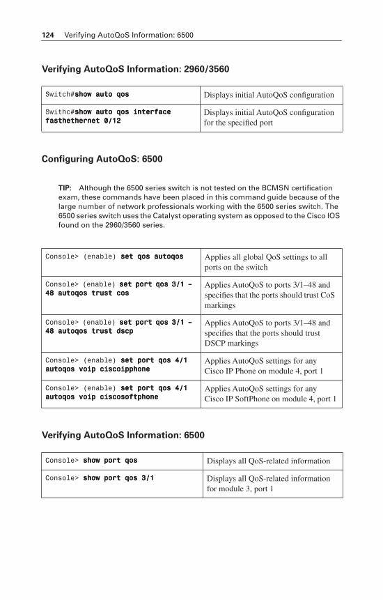
124 Verifying AutoQoS Information: 6500
Verifying AutoQoS Information: 2960/3560
Configuring AutoQoS: 6500
TIP: Although the 6500 series switch is not tested on the BCMSN certification exam, these commands have been placed in this command guide because of the large number of network professionals working with the 6500 series switch. The 6500 series switch uses the Catalyst operating system as opposed to the Cisco IOS found on the 2960/3560 series.
Verifying AutoQoS Information: 6500
Switch#sssshhhhoooowwww aaaauuuuttttoooo qqqqoooossss Displays initial AutoQoS configuration
Swithc#sssshhhhoooowwww aaaauuuuttttoooo qqqqoooossss iiiinnnntttteeeerrrrffffaaaacccceeee ffffaaaasssstttthhhheeeetttthhhheeeerrrrnnnneeeetttt 0000////11112222
Displays initial AutoQoS configuration for the specified port
Console> (enable) sssseeeetttt qqqqoooossss aaaauuuuttttooooqqqqoooossss Applies all global QoS settings to all ports on the switch
Console> (enable) sssseeeetttt ppppoooorrrrtttt qqqqoooossss 3333////1111 –––– 44448888 aaaauuuuttttooooqqqqoooossss ttttrrrruuuusssstttt ccccoooossss
Applies AutoQoS to ports 3/1–48 and specifies that the ports should trust CoS markings
Console> (enable) sssseeeetttt ppppoooorrrrtttt qqqqoooossss 3333////1111 –––– 44448888 aaaauuuuttttooooqqqqoooossss ttttrrrruuuusssstttt ddddssssccccpppp
Applies AutoQoS to ports 3/1–48 and specifies that the ports should trust DSCP markings
Console> (enable) sssseeeetttt ppppoooorrrrtttt qqqqoooossss 4444////1111 aaaauuuuttttooooqqqqoooossss vvvvooooiiiipppp cccciiiissssccccooooiiiipppppppphhhhoooonnnneeee
Applies AutoQoS settings for any Cisco IP Phone on module 4, port 1
Console> (enable) sssseeeetttt ppppoooorrrrtttt qqqqoooossss 4444////1111 aaaauuuuttttooooqqqqoooossss vvvvooooiiiipppp cccciiiissssccccoooossssooooffffttttpppphhhhoooonnnneeee
Applies AutoQoS settings for any Cisco IP SoftPhone on module 4, port 1
Console> sssshhhhoooowwww ppppoooorrrrtttt qqqqoooossss Displays all QoS-related information
Console> sssshhhhoooowwww ppppoooorrrrtttt qqqqoooossss 3333////1111 Displays all QoS-related information for module 3, port 1

APPENDIX
Create YourOwn Journal Here
Even though I have tried to be as complete as possible in this reference guide, invariably I will have left something out that you need in your specific day-to-day activities. That is why this section is here. Use these blank lines to enter in your own notes, making this reference guide your own personalized journal.

126 Appendix: Create Your Own Journal Here

Appendix: Create Your Own Journal Here 127

128 Appendix: Create Your Own Journal Here

Appendix: Create Your Own Journal Here 129

130 Appendix: Create Your Own Journal Here

Appendix: Create Your Own Journal Here 131

132 Appendix: Create Your Own Journal Here

Appendix: Create Your Own Journal Here 133

134 Appendix: Create Your Own Journal Here

Appendix: Create Your Own Journal Here 135

136 Appendix: Create Your Own Journal Here

Appendix: Create Your Own Journal Here 137

138 Appendix: Create Your Own Journal Here

Appendix: Create Your Own Journal Here 139

140 Appendix: Create Your Own Journal Here

Appendix: Create Your Own Journal Here 141

142 Appendix: Create Your Own Journal Here

Appendix: Create Your Own Journal Here 143

144 Appendix: Create Your Own Journal Here

Appendix: Create Your Own Journal Here 145

146 Appendix: Create Your Own Journal Here

Appendix: Create Your Own Journal Here 147

148 Appendix: Create Your Own Journal Here

Appendix: Create Your Own Journal Here 149

150 Appendix: Create Your Own Journal Here

Appendix: Create Your Own Journal Here 151

Visit the Cisco® CCNP® Prep Center for tools that will help with your CCNP certification studies. Site features include:
CCNP Prep CenterCCNP Preparation Support from Cisco
Visit the CCNP Prep Center at http://www.cisco.com/go/prep-ccnpand get started on your CCNP today!
• CCNP TV broadcasts, withexperts discussing CCNP topicsand answering your questions
• Study tips
• Practice questions
• Quizzes
• Discussion forums
• Job market information
• Quick learning modules
The site is free to anyone with a Cisco.com login.


![Applied Cisco Networking (CCNP BCMSN) - Napierbill/ccnp_bsmsn.pdf · 1 4 Feb Intro [A] Unit 1:Switch Basics [Lab A] Chapter 2: Designing Switched Networks ... Applied Cisco Networking](https://img.dokumen.tips/doc/110x75/5b90c29b09d3f2e6728cb21b/applied-cisco-networking-ccnp-bcmsn-billccnpbsmsnpdf-1-4-feb-intro-a.jpg)
![CCNP BCMSN Quick Reference Sheets - Lagout Quick Reference... · CCNP BCMSN Quick Reference Sheets Exam 642-812 ... [ 4 ] CCNP BCMSN Quick Reference Sheets. ... switch would be used](https://img.dokumen.tips/doc/110x75/5a7a6ec87f8b9a05538dccf5/ccnp-bcmsn-quick-reference-sheets-lagout-quick-referenceccnp-bcmsn-quick-reference.jpg)

![CCNP BCMSN Quick Reference Sheets - ipmanager.iripmanager.ir/r/Ebook/Cisco.Press.CCNP.BCMSN.Quick.Reference.Sheets...[ 4 ] CCNP BCMSN Quick Reference Sheets. ... — Clients attach](https://img.dokumen.tips/doc/110x75/5ad05c807f8b9a6c6c8e29ce/ccnp-bcmsn-quick-reference-sheets-4-ccnp-bcmsn-quick-reference-sheets-.jpg)


![Applied Cisco Networking (CCNP BCMSN) - …networksims.com/ccnp_bsmsn.pdf1 4 Feb Intro [A] Unit 1:Switch Basics [Lab A] Chapter 2: Designing Switched Networks ... Applied Cisco Networking](https://img.dokumen.tips/doc/110x75/5ad05c807f8b9a6c6c8e29b3/applied-cisco-networking-ccnp-bcmsn-4-feb-intro-a-unit-1switch-basics.jpg)


![Cisco® CCNP BCMSN Portable Command Guide [Chapter 5 - High Availability]](https://img.dokumen.tips/doc/110x75/55cf8fb9550346703b9f2e66/cisco-ccnp-bcmsn-portable-command-guide-chapter-5-high-availability.jpg)


![Ccnp Iscw Portable Command Guide Self Study Guide[1].9781587201868.31512](https://img.dokumen.tips/doc/110x75/5531e0d155034641568b4bc9/ccnp-iscw-portable-command-guide-self-study-guide1978158720186831512.jpg)

