Embed Size (px)
Citation preview

CCNA Security
Lab - Configuring an Intrusion Prevention System (IPS) Using the CLI and CCP
Topology
Note: ISR G2 devices use GigabitEthernet interfaces instead of FastEthernet Interfaces.
© 2015 Cisco and/or its affiliates. All rights reserved. This document is Cisco Public. Page 1 of 37

Lab – Configuring an Intrusion Prevention System (IPS) Using the CLI and CCP
IP Addressing Table
Device Interface IP Address Subnet Mask Default Gateway Switch Port
R1 Fa0/1 192.168.1.1 255.255.255.0 N/A S1 Fa0/5
S0/0/0 (DCE) 10.1.1.1 255.255.255.252 N/A N/A
R2 S0/0/0 10.1.1.2 255.255.255.252 N/A N/A
S0/0/1 (DCE) 10.2.2.2 255.255.255.252 N/A N/A
R3 Fa0/1 192.168.3.1 255.255.255.0 N/A S3 Fa0/5
S0/0/1 10.2.2.1 255.255.255.252 N/A N/A
PC-A NIC 192.168.1.3 255.255.255.0 192.168.1.1 S1 Fa0/6
PC-C NIC 192.168.3.3 255.255.255.0 192.168.3.1 S3 Fa0/18
Objectives Part 1: Configure Basic Router Settings
• Configure hostname, interface IP addresses, and access passwords.
• Configure the static routing.
Part 2: Use CLI to Configure an IOS IPS
• Configure IOS Intrusion Prevention System (IPS) using CLI.
• Modify IPS Signatures.
• Examine the resulting IPS configuration.
• Verify IPS functionality.
• Log IPS messages to a syslog server.
Part 3: Configure an IPS Using CCP
• Configure IPS using CCP.
• Modify IPS signatures.
• Examine the resulting IPS configuration.
• Use a scanning tool to simulate an attack.
• Use the CCP Monitor to verify IPS functionality.
Background / Scenario In this lab, you will configure the Cisco IOS Intrusion Prevention System (IPS), which is part of the Cisco IOS Firewall feature set. IPS examines certain attack patterns and alerts or mitigates when those patterns occur. IPS alone is not enough to make a router into a secure Internet firewall, but in addition to other security features, it can be a powerful defense.
You will configure IPS using the Cisco IOS CLI on one router and CCP on another router, and then test IPS functionality on both routers. You will load the IPS Signature package from a TFTP server and configure the public crypto key using the Cisco IOS CLI and CCP.
Note: The router commands and output in this lab are from a Cisco 1841 router with Cisco IOS Release 15.1(4)M8 (Advanced IP Services image). Other routers and Cisco IOS versions can be used. See the Router
© 2015 Cisco and/or its affiliates. All rights reserved. This document is Cisco Public. Page 2 of 37

Lab – Configuring an Intrusion Prevention System (IPS) Using the CLI and CCP
Interface Summary Table at the end of the lab to determine which interface identifiers to use based on the equipment in the lab. Depending on the router model and Cisco IOS version, the commands available and output produced might vary from what is shown in this lab.
Note: Ensure that the routers and switches have been erased and have no startup configurations.
Required Resources • 3 Routers (Cisco 1841 with Cisco IOS Release 15.1(4)M8 Advanced IP Services image or comparable)
• 2 Switches (Cisco 2960 or comparable)
• 2 PCs (Windows Vista or Windows 7 with CCP 2.5, Tftpd32 server, Nmap/Zenmap, latest version of Java, Internet Explorer, and Flash Player)
• Serial and Ethernet cables as shown in the topology
• Console cables to configure Cisco networking devices
• IPS Signature package and public crypto key files on PC-A and PC-C (provided by instructor) CCP Notes:
• If the PC on which CCP is installed is running Windows Vista or Windows 7, it may be necessary to right-click the CCP icon, and select Run as administrator.
• To run CCP, it may be necessary to temporarily disable antivirus programs and O/S firewalls. Ensure that all pop-up blockers are turned off in the browser.
Part 1: Configure Basic Router Settings In Part 1, you will set up the network topology and configure basic settings, such as hostnames, interface IP addresses, static routing, device access, and passwords.
Note: Perform steps listed in Part 1 on all three routers, only R1 is shown below.
Step 1: Cable the network as shown in the topology. Attach the devices, as shown in the topology diagram, and cable as necessary.
Step 2: Configure the basic settings for each router. a. Configure the hostnames, as shown in the topology.
b. Configure the interface IP addresses, as shown in the IP Addressing table.
c. Configure a clock rate for serial router interfaces with a DCE serial cable attached. R1(config)# interface S0/0/0 R1(config-if)# clock rate 64000
d. To prevent the router from attempting to translate incorrectly entered commands, disable DNS lookup. R1(config)# no ip domain-lookup
Step 3: Configure static routing on the routers. a. Configure a static default route from R1 to R2 and from R3 to R2.
b. Configure a static route from R2 to the R1 LAN and from R2 to the R3 LAN.
© 2015 Cisco and/or its affiliates. All rights reserved. This document is Cisco Public. Page 3 of 37

Lab – Configuring an Intrusion Prevention System (IPS) Using the CLI and CCP
Step 4: Configure PC host IP settings. Configure a static IP address, subnet mask, and default gateway for PC-A and PC-C, as shown in the IP Addressing table.
Step 5: Verify basic network connectivity. a. Ping from R1 to R3.
If the pings are unsuccessful, troubleshoot the basic device configurations before continuing.
b. Ping from PC-A on the R1 LAN to PC-C on the R3 LAN.
If the pings are unsuccessful, troubleshoot the basic device configurations before continuing.
Note: If you can ping from PC-A to PC-C, you have demonstrated that the static routing protocol is configured and functioning correctly. If you cannot ping, but the device interfaces are up and IP addresses are correct, use the show run and show ip route commands to identify routing protocol-related problems.
Step 6: Configure and encrypt passwords. Note: Passwords in this task are set to a minimum of 10 characters, but are relatively simple for the benefit of performing the lab. More complex passwords are recommended in a production network.
a. Configure a minimum password length using the security passwords command to set a minimum password length of 10 characters. R1(config)# security passwords min-length 10
b. Configure a console password and enable login for router R1. For additional security, the exec-timeout command causes the line to log out after 5 minutes of inactivity. The logging synchronous command prevents console messages from interrupting command entry.
Note: To avoid repetitive logins during this lab, the exec-timeout command can be set to 0 0, which prevents it from expiring; however, this is not considered to be a good security practice. R1(config)# line console 0 R1(config-line)# password ciscoconpass R1(config-line)# exec-timeout 5 0 R1(config-line)# login R1(config-line)# logging synchronous
c. Configure a password for the aux port for router R1. R1(config)# line aux 0 R1(config-line)# password ciscoauxpass R1(config-line)# exec-timeout 5 0 R1(config-line)# login
d. Configure the password on the vty lines for router R1. R1(config)# line vty 0 4 R1(config-line)# password ciscovtypass R1(config-line)# exec-timeout 5 0 R1(config-line)# login
e. Encrypt the console, aux, and vty clear text passwords. R1(config)# service password-encryption
Issue the show run command. Can you read the console, aux, and vty passwords? Explain.
____________________________________________________________________________________
© 2015 Cisco and/or its affiliates. All rights reserved. This document is Cisco Public. Page 4 of 37

Lab – Configuring an Intrusion Prevention System (IPS) Using the CLI and CCP
Step 7: Save the basic configurations for all three routers. Save the running configuration to the startup configuration from the privileged EXEC mode prompt.
R1# copy running-config startup-config
Part 2: Configuring IPS Using the Cisco IOS CLI In Part 2 of this lab, you will configure IPS on R1 using the Cisco IOS CLI. You then review and test the resulting configuration.
Task 1: Verify Access to the R1 LAN from R2 In this task, you will verify that without IPS configured, the external router R2 can ping the R1 S0/0/0 interface and PC-A on the R1 internal LAN.
Step 1: Ping from R2 to R1. From R2, ping R1 interface S0/0/0 at IP address 10.1.1.1.
R2# ping 10.1.1.1
If the pings are unsuccessful, troubleshoot the basic device configurations before continuing.
Step 2: Ping from R2 to PC-A on the R1 LAN. From R2, ping PC-A on the R1 LAN at IP address 192.168.1.3.
R2# ping 192.168.1.3
If the pings are unsuccessful, troubleshoot the basic device configurations before continuing.
Step 3: Display the R1 running configuration prior to configuring IPS. Issue the show run command to review the current basic configuration on R1.
Are there any security commands related to IPS?
_______________________________________________________________________________________
_______________________________________________________________________________________
_______________________________________________________________________________________
Task 2: Prepare the Router and TFTP Server
Step 1: Verify the availability of Cisco IOS IPS files. To configure Cisco IOS IPS 5.x, the IOS IPS Signature package file and public crypto key file must be available on PC-A. Check with your instructor if these files are not on the PC. These files can be downloaded from www.cisco.com with a valid user account that has proper authorization.
a. Verify that the IOS-Sxxx-CLI.pkg file is in a TFTP folder. This is the signature package. The xxx is the version number and varies depending on which file was downloaded.
b. Verify that the realm-cisco.pub.key.txt file is available and note its location on PC-A. This is the public crypto key used by IOS IPS.
Step 2: Verify or create the IPS directory in router flash on R1. a. In this step, you will verify the existence of, or create a directory in, the router flash memory where the
required signature files and configurations will be stored.
© 2015 Cisco and/or its affiliates. All rights reserved. This document is Cisco Public. Page 5 of 37
Lab – Configuring an Intrusion Prevention System (IPS) Using the CLI and CCP
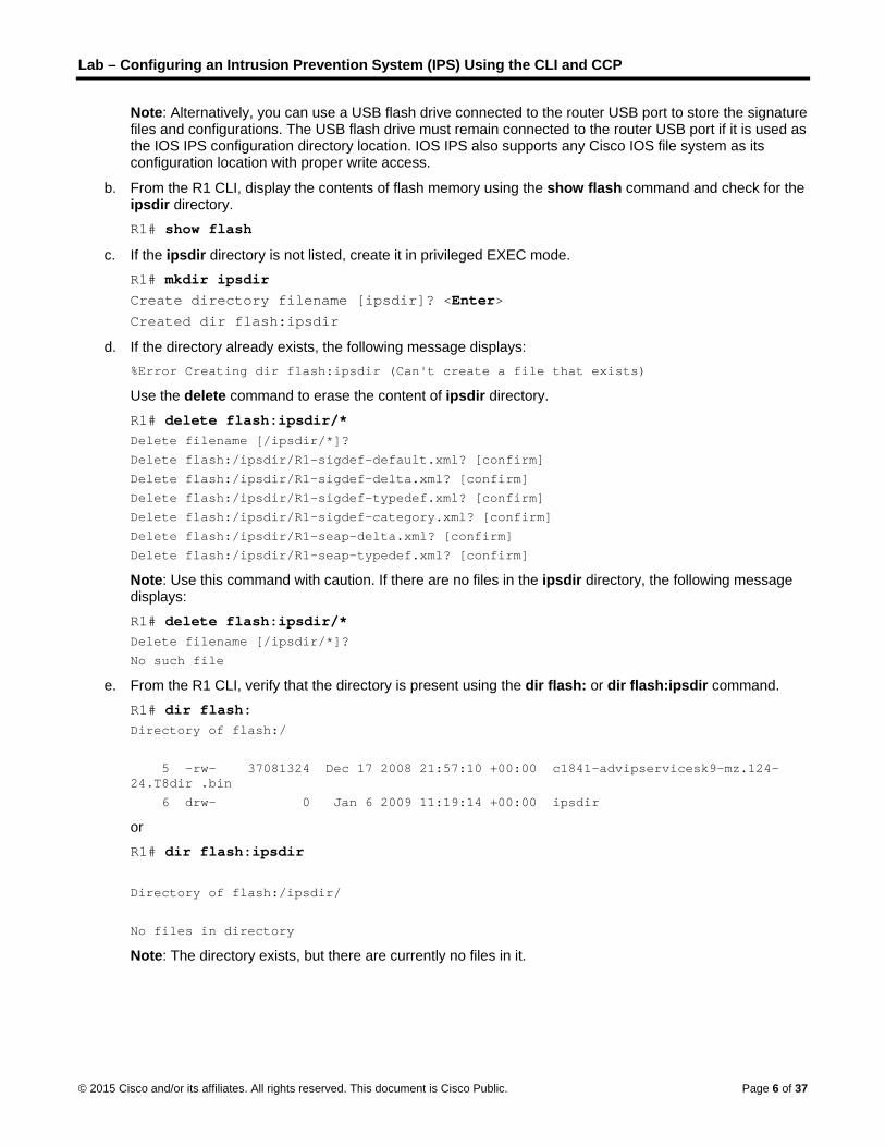
Note: Alternatively, you can use a USB flash drive connected to the router USB port to store the signature files and configurations. The USB flash drive must remain connected to the router USB port if it is used as the IOS IPS configuration directory location. IOS IPS also supports any Cisco IOS file system as its configuration location with proper write access.
b. From the R1 CLI, display the contents of flash memory using the show flash command and check for the ipsdir directory. R1# show flash
c. If the ipsdir directory is not listed, create it in privileged EXEC mode. R1# mkdir ipsdir Create directory filename [ipsdir]? <Enter> Created dir flash:ipsdir
d. If the directory already exists, the following message displays: %Error Creating dir flash:ipsdir (Can't create a file that exists)
Use the delete command to erase the content of ipsdir directory. R1# delete flash:ipsdir/* Delete filename [/ipsdir/*]?
Delete flash:/ipsdir/R1-sigdef-default.xml? [confirm]
Delete flash:/ipsdir/R1-sigdef-delta.xml? [confirm]
Delete flash:/ipsdir/R1-sigdef-typedef.xml? [confirm]
Delete flash:/ipsdir/R1-sigdef-category.xml? [confirm]
Delete flash:/ipsdir/R1-seap-delta.xml? [confirm]
Delete flash:/ipsdir/R1-seap-typedef.xml? [confirm]
Note: Use this command with caution. If there are no files in the ipsdir directory, the following message displays: R1# delete flash:ipsdir/* Delete filename [/ipsdir/*]?
No such file
e. From the R1 CLI, verify that the directory is present using the dir flash: or dir flash:ipsdir command. R1# dir flash: Directory of flash:/
5 -rw- 37081324 Dec 17 2008 21:57:10 +00:00 c1841-advipservicesk9-mz.124-24.T8dir .bin
6 drw- 0 Jan 6 2009 11:19:14 +00:00 ipsdir
or R1# dir flash:ipsdir Directory of flash:/ipsdir/
No files in directory
Note: The directory exists, but there are currently no files in it.
© 2015 Cisco and/or its affiliates. All rights reserved. This document is Cisco Public. Page 6 of 37
Lab – Configuring an Intrusion Prevention System (IPS) Using the CLI and CCP
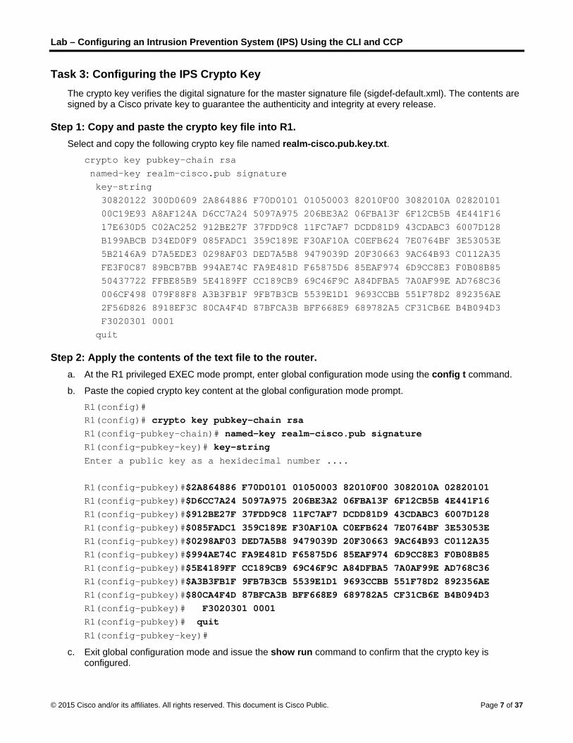
Task 3: Configuring the IPS Crypto Key The crypto key verifies the digital signature for the master signature file (sigdef-default.xml). The contents are signed by a Cisco private key to guarantee the authenticity and integrity at every release.
Step 1: Copy and paste the crypto key file into R1. Select and copy the following crypto key file named realm-cisco.pub.key.txt.
crypto key pubkey-chain rsa
named-key realm-cisco.pub signature
key-string
30820122 300D0609 2A864886 F70D0101 01050003 82010F00 3082010A 02820101 00C19E93 A8AF124A D6CC7A24 5097A975 206BE3A2 06FBA13F 6F12CB5B 4E441F16
17E630D5 C02AC252 912BE27F 37FDD9C8 11FC7AF7 DCDD81D9 43CDABC3 6007D128
B199ABCB D34ED0F9 085FADC1 359C189E F30AF10A C0EFB624 7E0764BF 3E53053E
5B2146A9 D7A5EDE3 0298AF03 DED7A5B8 9479039D 20F30663 9AC64B93 C0112A35
FE3F0C87 89BCB7BB 994AE74C FA9E481D F65875D6 85EAF974 6D9CC8E3 F0B08B85 50437722 FFBE85B9 5E4189FF CC189CB9 69C46F9C A84DFBA5 7A0AF99E AD768C36
006CF498 079F88F8 A3B3FB1F 9FB7B3CB 5539E1D1 9693CCBB 551F78D2 892356AE
2F56D826 8918EF3C 80CA4F4D 87BFCA3B BFF668E9 689782A5 CF31CB6E B4B094D3
F3020301 0001
quit
Step 2: Apply the contents of the text file to the router. a. At the R1 privileged EXEC mode prompt, enter global configuration mode using the config t command.
b. Paste the copied crypto key content at the global configuration mode prompt.
R1(config)# R1(config)# crypto key pubkey-chain rsa R1(config-pubkey-chain)# named-key realm-cisco.pub signature R1(config-pubkey-key)# key-string Enter a public key as a hexidecimal number ....
R1(config-pubkey)#$2A864886 F70D0101 01050003 82010F00 3082010A 02820101 R1(config-pubkey)#$D6CC7A24 5097A975 206BE3A2 06FBA13F 6F12CB5B 4E441F16 R1(config-pubkey)#$912BE27F 37FDD9C8 11FC7AF7 DCDD81D9 43CDABC3 6007D128 R1(config-pubkey)#$085FADC1 359C189E F30AF10A C0EFB624 7E0764BF 3E53053E R1(config-pubkey)#$0298AF03 DED7A5B8 9479039D 20F30663 9AC64B93 C0112A35 R1(config-pubkey)#$994AE74C FA9E481D F65875D6 85EAF974 6D9CC8E3 F0B08B85 R1(config-pubkey)#$5E4189FF CC189CB9 69C46F9C A84DFBA5 7A0AF99E AD768C36 R1(config-pubkey)#$A3B3FB1F 9FB7B3CB 5539E1D1 9693CCBB 551F78D2 892356AE R1(config-pubkey)#$80CA4F4D 87BFCA3B BFF668E9 689782A5 CF31CB6E B4B094D3 R1(config-pubkey)# F3020301 0001 R1(config-pubkey)# quit R1(config-pubkey-key)#
c. Exit global configuration mode and issue the show run command to confirm that the crypto key is configured.
© 2015 Cisco and/or its affiliates. All rights reserved. This document is Cisco Public. Page 7 of 37

Lab – Configuring an Intrusion Prevention System (IPS) Using the CLI and CCP
Task 4: Configure IPS
Step 1: Create an IPS rule. a. On R1, create an IPS rule name using the ip ips name name command in global configuration mode.
Name the IPS rule iosips. This will be used later on an interface to enable IPS. R1(config)# ip ips name iosips
b. You can specify an optional extended or standard access control list (ACL) to filter the traffic that will be scanned by this rule name. All traffic permitted by the ACL is subject to inspection by the IPS. Traffic that is denied by the ACL is not inspected by the IPS.
c. To see the options available for specifying an ACL with the rule name, use the ip ips name command and the CLI help function (?).
R1(config)# ip ips name ips list ? <1-199> Numbered access list
WORD Named access list
Step 2: Configure the IPS Signature storage location in router flash memory. The IPS files will be stored in the ipsdir directory that was created in Task 2, Step 2. Configure the location using the ip ips config location command.
R1(config)# ip ips config location flash:ipsdir
Step 3: Enable IPS SDEE event notification. The Cisco Security Device Event Exchange (SDEE) server is a Simple Object Access Protocol (SOAP) based, intrusion detection system (IDS) alert format and transport protocol specification. SDEE replaces Cisco RDEP.
To use SDEE, the HTTP server must be enabled with the ip http server command. If the HTTP server is not enabled, the router cannot respond to the SDEE clients, because it cannot see the requests. SDEE notification is disabled, by default, and must be explicitly enabled.
R1(config)# ip http server
Note: CCP Monitor uses HTTP and SDEE to capture IPS events.
To enable SDEE, use the following command: R1(config)# ip ips notify sdee
Step 4: Enable IPS syslog support. IOS IPS also supports the use of syslog to send event notifications. SDEE and syslog can be used independently or enabled at the same time to send IOS IPS event notification. Syslog notification is enabled by default.
a. If console logging is enabled, IPS syslog messages display. Enable syslog if it is not enabled. R1(config)# ip ips notify log
b. Use the show clock command to verify the current time and date for the router. Use the clock set command in privileged EXEC mode to reset the clock if necessary. The following example shows how to set the clock. R1# clock set 01:20:00 6 january 2009
c. Verify that the timestamp service for logging is enabled on the router using the show run command. Enable the timestamp service if it is not enabled.
© 2015 Cisco and/or its affiliates. All rights reserved. This document is Cisco Public. Page 8 of 37

Lab – Configuring an Intrusion Prevention System (IPS) Using the CLI and CCP
R1(config)# service timestamps log datetime msec
d. To send log messages to the syslog server on PC-A, use the following command: R1(config)# logging 192.168.1.3
e. To see the type and level of logging enabled on R1, use the show logging command. R1# show logging
Note: Verify that you have connectivity between R1 and PC-A by pinging from PC-A to the R1 Fa0/1 interface IP address 192.168.1.1. If it is not successful, troubleshoot as necessary before continuing.
The next step describes how to download one of the freeware syslog servers if one is unavailable on PC-A.
Step 5: (Optional) Download and start the syslog server. If a syslog server is not currently available on PC-A, you can download the Tftpd32 from http://tftpd32.jounin.net/. If the syslog server is available on the PC, go to Step 6.
Start the syslog server software on PC-A to send log messages to it.
Step 6: Configure IOS IPS to use one of the pre-defined signature categories. IOS IPS with Cisco 5.x format signatures operates with signature categories, just like Cisco IPS appliances do. All signatures are pre-grouped into categories, and the categories are hierarchical. This helps classify signatures for easy grouping and tuning.
Warning: The “all” signature category contains all signatures in a signature release. Because IOS IPS cannot compile and use all the signatures contained in a signature release at one time, do not unretire the “all” category. Otherwise, the router will run out of memory.
Note: When configuring IOS IPS, it is required to first retire all the signatures in the “all” category and then unretire selected signature categories.
In the following example, all signatures in the all category are retired, and then the ios_ips basic category is unretired.
R1(config)# ip ips signature-category R1(config-ips-category)# category all R1(config-ips-category-action)# retired true R1(config-ips-category-action)# exit R1(config-ips-category)# category ios_ips basic R1(config-ips-category-action)# retired false R1(config-ips-category-action)# exit R1(config-ips-category)# exit Do you want to accept these changes? [confirm] <Enter>
Jan 6 01:32:37.983: Applying Category configuration to signatures ...
Step 7: Apply the IPS rule to an interface. a. Apply the IPS rule to an interface with the ip ips name direction command in interface configuration
mode. Apply the rule you just created inbound on the S0/0/0 interface. After you enable IPS, some log messages will be sent to the console line indicating that the IPS engines are being initialized.
Note: The direction in means that IPS inspects only traffic going into the interface. Similarly, out means only traffic going out the interface. To enable IPS to inspect both in and out traffic, enter the IPS rule name for in and out separately on the same interface. R1(config)# interface serial0/0/0
© 2015 Cisco and/or its affiliates. All rights reserved. This document is Cisco Public. Page 9 of 37

Lab – Configuring an Intrusion Prevention System (IPS) Using the CLI and CCP
R1(config-if)# ip ips iosips in Jan 6 03:03:30.495: %IPS-6-ENGINE_BUILDS_STARTED: 03:03:30 UTC Jan 6 2008
Jan 6 03:03:30.495: %IPS-6-ENGINE_BUILDING: atomic-ip - 3 signatures - 1 of 13 engines
Jan 6 03:03:30.511: %IPS-6-ENGINE_READY: atomic-ip - build time 16 ms – packets for this engine will be scanned
Jan 6 03:03:30.511: %IPS-6-ALL_ENGINE_BUILDS_COMPLETE: elapsed time 16 ms
The message also displays on the syslog server if it is enabled. The Tftpd32 syslog server is shown here.
Note: The following message may display if the router does not have built-in IOS signature file. *******************************************************************
The signature package is missing or was saved by a previous version
IPS Please load a new signature package
*******************************************************************
Jan 6 01:22:17.383: %IPS-3-SIG_UPDATE_REQUIRED: IOS IPS requires a signature update package to be loaded
b. Although the R1 Fa0/1 interface is an internal interface, configure it with IPS to respond to internal attacks. Apply the IPS rule to the R1 Fa0/1 interface in the inbound direction. R1(config)# interface fa0/1 R1(config-if)# ip ips iosips in
Step 8: Save the running configuration. Enter privileged EXEC mode using the enable command and provide the enable password cisco12345.
R1# copy run start
Task 5: Load the IOS IPS Signature Package to the Router The most common way to load the signature package to the router is to use TFTP. Refer to Step 4 for alternative methods for loading the IOS IPS signature package. The alternative methods include the use of FTP and a USB flash drive.
© 2015 Cisco and/or its affiliates. All rights reserved. This document is Cisco Public. Page 10 of 37

Lab – Configuring an Intrusion Prevention System (IPS) Using the CLI and CCP
Step 1: (Optional) Download the TFTP server. The Tftpd32 freeware TFTP server is used in this task. Many other free TFTP servers are also available. If a TFTP server is currently unavailable on PC-A, you can download the latest version of Tftpd32 from http://tftpd32.jounin.net/. If it is already installed, go to Step 2.
Note: This lab uses the Tftpd32 TFTP server. This software also includes a syslog server, which runs simultaneously with the TFTP server.
Step 2: Start the TFTP server on PC-A and verify the IPS file directory. a. Verify connectivity between R1 and PC-A, the TFTP server, using the ping command.
b. Verify that the PC has the IPS Signature package file in a directory on the TFTP server. This file is typically named IOS-Sxxx-CLI.pkg, where xxx is the signature file version.
Note: If this file is not present, contact your instructor before continuing.
c. Start Tftpd32 or another TFTP server and set the default directory to the one with the IPS Signature package in it. The Tftpd32 screen is shown here with the C:\Program Files\Tftpd32\IPS directory contents displayed. Take note of the filename for use in the next step.
Note: It is recommended to use the latest signature file available in a production environment. However, if the amount of router flash memory is an issue in a lab environment, you may use an older version 5.x signature, which requires less memory. The S364 file is used with this lab for demonstration purposes, although newer versions are available. Consult CCO to determine the latest version.
Step 3: Copy the signature package from the TFTP server to the router. If you do not have a TFTP server available, and you are using a router with a USB port, go to Step 5 and use the procedure described there.
a. Use the copy tftp command to retrieve the signature file and load it into the Intrusion Detection Configuration. Use the idconf keyword at the end of the copy command.
Note: Immediately after the signature package is loaded to the router, signature compiling begins. You can see the messages on the router with logging level 6 or above enabled. R1# copy tftp://192.168.1.3/IOS-S364-CLI.pkg idconf
© 2015 Cisco and/or its affiliates. All rights reserved. This document is Cisco Public. Page 11 of 37

Lab – Configuring an Intrusion Prevention System (IPS) Using the CLI and CCP
Loading IOS-S364-CLI.pkg from 192.168.1.3 (via FastEthernet0/1): !!!!!!!!!!!!!!!!!!!!!!!!!!
[OK - 6654646 bytes]
Jan 6 03:18:36.799: %IPS-6-ENGINE_BUILDS_STARTED: 03:18:36 UTC Jan 6 2008
Jan 6 03:18:36.799: %IPS-6-ENGINE_BUILDING: multi-string - 8 signatures - 1 of 13 engines
Jan 6 03:18:36.811: %IPS-6-ENGINE_READY: multi-string - build time 12 ms - packets for this engine will be scanned
Jan 6 03:18:36.831: %IPS-6-ENGINE_BUILDING: service-http - 629 signatures - 2 of 13 engines
Jan 6 03:18:46.755: %IPS-6-ENGINE_READY: service-http - build time 9924 ms - packets for this engine will be scanned
<Output omitted>
b. Use the dir flash command to see the contents of the ipsdir directory created earlier. There should be six files, as shown here. R1# dir flash:ipsdir Directory of flash:/ipsdir/
16 -rw- 230621 Jan 6 2008 03:19:42 +00:00 R1-sigdef-default.xml
15 -rw- 255 Jan 6 2008 01:35:26 +00:00 R1-sigdef-delta.xml
14 -rw- 6632 Jan 6 2008 03:17:48 +00:00 R1-sigdef-typedef.xml
13 -rw- 28282 Jan 6 2008 03:17:52 +00:00 R1-sigdef-category.xml
10 -rw- 304 Jan 6 2008 01:35:28 +00:00 R1-seap-delta.xml
18 -rw- 491 Jan 6 2008 01:35:28 +00:00 R1-seap-typedef.xml
Step 4: Verify that the signature package is properly compiled. a. Use the show ip ips signature count command to see the counts for the signature package compiled.
R1# show ip ips signature count
Cisco SDF release version S364.0
Trend SDF release version V0.0
Signature Micro-Engine: multi-string: Total Signatures 11
multi-string enabled signatures: 9
multi-string retired signatures: 11
Signature Micro-Engine: service-http: Total Signatures 662
service-http enabled signatures: 163
service-http retired signatures: 565
service-http compiled signatures: 97
service-http obsoleted signatures: 1
Signature Micro-Engine: string-tcp: Total Signatures 1148
string-tcp enabled signatures: 622
string-tcp retired signatures: 1031
string-tcp compiled signatures: 117
string-tcp obsoleted signatures: 21
© 2015 Cisco and/or its affiliates. All rights reserved. This document is Cisco Public. Page 12 of 37

Lab – Configuring an Intrusion Prevention System (IPS) Using the CLI and CCP
<Output Omitted>
Total Signatures: 2435
Total Enabled Signatures: 1063
Total Retired Signatures: 2097
Total Compiled Signatures: 338
Total Obsoleted Signatures: 25
Note: If you see an error message during signature compilation, such as “%IPS-3-INVALID_DIGITAL_SIGNATURE: Invalid Digital Signature found (key not found),” it means the public crypto key is invalid. Refer to Task 3, Configure the IPS Crypto Key, to reconfigure the public crypto key.
b. Use the show ip ips all command to view the IPS configuration status summary. To which interfaces and in which direction is the iosips rule applied?
____________________________________________________________________________________
____________________________________________________________________________________ R1# show ip ips all
IPS Signature File Configuration Status
Configured Config Locations: flash:ipsdir/
Last signature default load time: 18:47:52 UTC Jan 6 2009
Last signature delta load time: 20:11:35 UTC Jan 6 2009
Last event action (SEAP) load time: -none-
General SEAP Config:
Global Deny Timeout: 3600 seconds
Global Overrides Status: Enabled
Global Filters Status: Enabled
IPS Auto Update is not currently configured
IPS Syslog and SDEE Notification Status
Event notification through syslog is enabled
Event notification through SDEE is enabled
IPS Signature Status
Total Active Signatures: 339
Total Inactive Signatures: 2096
IPS Packet Scanning and Interface Status
IPS Rule Configuration
IPS name iosips
IPS fail closed is disabled
IPS deny-action ips-interface is false
Interface Configuration
Interface Serial0/0/0
Inbound IPS rule is iosips
Outgoing IPS rule is not set
Interface FastEthernet0/1
Inbound IPS rule is iosips
© 2015 Cisco and/or its affiliates. All rights reserved. This document is Cisco Public. Page 13 of 37

Lab – Configuring an Intrusion Prevention System (IPS) Using the CLI and CCP
Outgoing IPS rule is not set
IPS Category CLI Configuration:
Category all:
Retire: True
Category ios_ips basic:
Retire: False
Step 5: (Optional) Alternative methods of copying the signature package to the router. If you used TFTP to copy the file and will not use one of these alternative methods, read through the procedures described here to become familiar with them. If you use one of these methods instead of TFTP, return to Step 4 to verify that the signature package loaded properly.
FTP method: Although the TFTP method is generally adequate, the signature file is rather large and FTP can provide another method of copying the file. You can use an FTP server to copy the signature file to the router with this command:
copy ftp://<ftp_user:password@Server_IP_address>/<signature_package> idconf
In the following example, the user admin must be defined on the FTP server with a password of cisco. R1# copy ftp://admin:[email protected]/IOS-S364-CLI.pkg idconf Loading IOS-S364-CLI.pkg !!!!!!!!!!!!!!!!!!!!!!!!!!!!!!
[OK - 7608873/4096 bytes]
USB method: If there is no access to a FTP or TFTP server, you can use a USB flash drive to load the signature package to the router.
a. Copy the signature package onto the USB drive.
b. Connect the USB drive to one of the USB ports on the router.
c. Use the show file systems command to see the name of the USB drive. In the following output, a 4 GB USB drive is connected to the USB port on the router as file system usbflash0: R1# show file systems File Systems:
Size(b) Free(b) Type Flags Prefixes
- - opaque rw archive:
- - opaque rw system:
- - opaque rw tmpsys:
- - opaque rw null: - - network rw tftp:
196600 185972 nvram rw nvram:
* 64012288 14811136 disk rw flash:#
- - opaque wo syslog:
- - opaque rw xmodem: - - opaque rw ymodem:
- - network rw rcp:
- - network rw pram:
- - network rw http:
- - network rw ftp: - - network rw scp:
© 2015 Cisco and/or its affiliates. All rights reserved. This document is Cisco Public. Page 14 of 37

Lab – Configuring an Intrusion Prevention System (IPS) Using the CLI and CCP
- - opaque ro tar:
- - network rw https:
- - opaque ro cns: 4001378304 3807461376 usbflash rw usbflash0:
d. Verify the contents of the flash drive using the dir command. R1# dir usbflash0: Directory of usbflash0:/ 90 -rw- 6654646 Jan 5 2009 14:49:34 +00:00 IOS-S364-CLI.pkg
91 -rw- 805 Jan 5 2009 14:49:34 +00:00 realm-cisco.pub.key.txt
e. Use the copy command with the idconf keyword to copy the signature package to the router. R1# copy usbflash0:IOS-S364-CLI.pkg idconf
The USB copy process can take 60 seconds or more, and no progress indicator displays. When the copy process is complete, numerous engine building messages display. These must finish before the command prompt returns.
Task 6: Test the IPS Rule and Modify a Signature You can work with signatures in many ways. They can be retired and unretired, enabled and disabled, and their characteristics and actions can be changed. In this task, you first test the default behavior of IOS IPS by pinging it from the outside.
Step 1: Ping from R2 to the R1 serial 0/0/0 interface. From the CLI on R2, ping R1 S0/0/0 at IP address 10.1.1.1. The pings are successful because the ICMP Echo Request signature 2004:0 is retired.
Step 2: Ping from R2 to PC-A. From the CLI on R2, ping PC-A at IP address 192.168.1.3. These pings are also successful because of the retired signature. This is the default behavior of the IPS signatures.
R2# ping 192.168.1.3 Type escape sequence to abort.
Sending 5, 100-byte ICMP Echos to 192.168.1.3, timeout is 2 seconds:
!!!!!
Success rate is 100 percent (5/5), round-trip min/avg/max = 1/1/4 ms
Step 3: Modify the signature. You can use the Cisco IOS CLI to change signature status and actions for one signature or a group of signatures based on signature categories.
The following example shows how to unretire the echo request signature, enable it, change the signature action to alert, and drop and reset for signature 2004 with a subsig ID of 0.
R1(config)# ip ips signature-definition R1(config-sigdef)# signature 2004 0 R1(config-sigdef-sig)#status R1(config-sigdef-sig-status)# retired false R1(config-sigdef-sig-status)# enabled true R1(config-sigdef-sig-status)# engine
© 2015 Cisco and/or its affiliates. All rights reserved. This document is Cisco Public. Page 15 of 37

Lab – Configuring an Intrusion Prevention System (IPS) Using the CLI and CCP
R1(config-sigdef-sig-engine)# event-action produce-alert R1(config-sigdef-sig-engine)# event-action deny-packet-inline R1(config-sigdef-sig-engine)# event-action reset-tcp-connection R1(config-sigdef-sig-engine)# exit R1(config-sigdef-sig)# exit R1(config-sigdef)# exit Do you want to accept these changes? [confirm] <Enter> *Jan 6 19:36:56.459: %IPS-6-ENGINE_BUILDS_STARTED: 19:36:56 UTC Jan 6 2009
*Jan 6 19:36:56.891: %IPS-6-ENGINE_BUILDING: atomic-ip - 306 signatures - 1 of 13 engines
*Jan 6 19:36:57.599: %IPS-6-ENGINE_READY: atomic-ip - build time 704 ms - packets for this engine will be scanned *Jan 6 19:36:57.979: %IPS-6-ALL_ENGINE_BUILDS_COMPLETE: elapsed time 1520 ms
Step 4: Ping from R2 to R1 serial 0/0/0 interface. a. Start the syslog server.
b. From the CLI on R2, ping R1 S0/0/0 at IP address 10.1.1.1. Where the pings successful? Explain.
____________________________________________________________________________________
____________________________________________________________________________________
Step 5: Ping from R2 to PC-A. a. From the CLI on R2, ping PC-A at IP address 192.168.1.3. Were the pings successful? Explain.
____________________________________________________________________________________
____________________________________________________________________________________
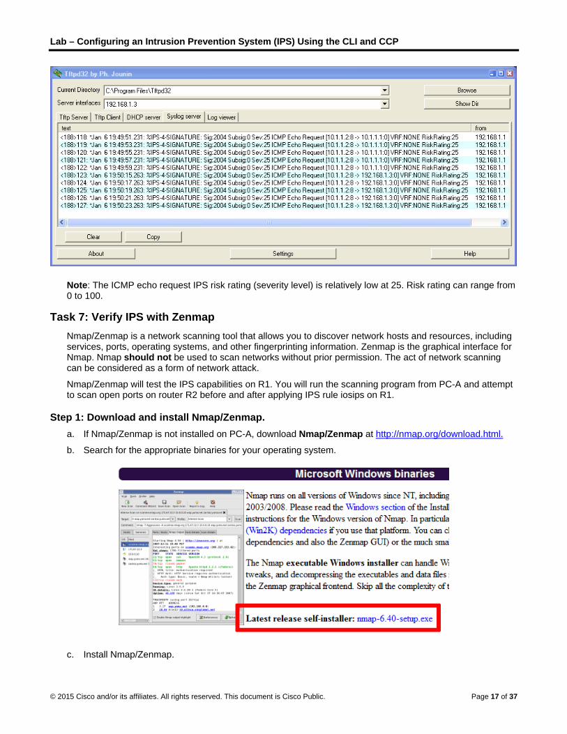
b. Notice the IPS messages from R1 on the syslog server screen below. How many messages were generated from the R2 pings to R1 and PC-A?
____________________________________________________________________________________
____________________________________________________________________________________
© 2015 Cisco and/or its affiliates. All rights reserved. This document is Cisco Public. Page 16 of 37
Lab – Configuring an Intrusion Prevention System (IPS) Using the CLI and CCP
Note: The ICMP echo request IPS risk rating (severity level) is relatively low at 25. Risk rating can range from 0 to 100.
Task 7: Verify IPS with Zenmap Nmap/Zenmap is a network scanning tool that allows you to discover network hosts and resources, including services, ports, operating systems, and other fingerprinting information. Zenmap is the graphical interface for Nmap. Nmap should not be used to scan networks without prior permission. The act of network scanning can be considered as a form of network attack.
Nmap/Zenmap will test the IPS capabilities on R1. You will run the scanning program from PC-A and attempt to scan open ports on router R2 before and after applying IPS rule iosips on R1.
Step 1: Download and install Nmap/Zenmap. a. If Nmap/Zenmap is not installed on PC-A, download Nmap/Zenmap at http://nmap.org/download.html.
b. Search for the appropriate binaries for your operating system.
c. Install Nmap/Zenmap.
© 2015 Cisco and/or its affiliates. All rights reserved. This document is Cisco Public. Page 17 of 37

Lab – Configuring an Intrusion Prevention System (IPS) Using the CLI and CCP
Step 2: Run Nmap/Zenmap and set scanning options. a. Start Zenmap on PC-A.
b. Enter IP address 10.1.1.2 as the Target and verify that Intense scan is selected as the Profile. Click Scan to begin the scan.
c. After the scan is complete, review the results displayed in the Nmap Output tab.
d. Click the Ports/Hosts tab. How many open ports did Nmap find on R2? What are the associated port numbers and services?
____________________________________________________________________________________
____________________________________________________________________________________
e. Exit Zenmap.
Task 8: Observe the syslog messages on R1. You should see syslog entries on the R1 console and on the syslog server if it is enabled. The descriptions should include phrases, such as TCP NULL Packet and TCP SYN/FIN Packet.
R1# .Jan 6 01:51:13.050: %IPS-4-SIGNATURE: Sig:2004 Subsig:0 Sev:25 ICMP Echo Request [192.168.1.3:8 -> 10.1.1.2:0] VRF:NONE RiskRating:25
.Jan 6 01:51:13.082: %IPS-4-SIGNATURE: Sig:3040 Subsig:0 Sev:100 TCP NULL Packet [192.168.1.3:33455 -> 10.1.1.2:23] VRF:NONE RiskRating:100
.Jan 6 01:51:13.114: %IPS-4-SIGNATURE: Sig:3041 Subsig:0 Sev:100 TCP SYN/FIN Packet [192.168.1.3:33456 -> 10.1.1.2:23] VRF:NONE RiskRating:100
a. What is the IPS risk rating or severity level (Sev:) of the TCP NULL Packet, signature 3040?
____________________________________________________________________________________
b. What is the IPS risk rating or severity level (Sev:) of the TCP SYN/FIN packet, signature 3041?
© 2015 Cisco and/or its affiliates. All rights reserved. This document is Cisco Public. Page 18 of 37

Lab – Configuring an Intrusion Prevention System (IPS) Using the CLI and CCP
____________________________________________________________________________________
Part 3: Configuring an IPS using CCP In Part 3 of this lab, you will configure IOS IPS on R3 using CCP.
Task 1: Configure Java Settings on PC-C The next-generation Java Plug-in must be enabled, and the Security setting must be set to Medium for the CCP configuration of IPS. To support the CCP configuration of IPS, PC-C should be running Java JRE version 6 or newer to set the Java heap to 256 MB. This is done using the–Xmx256m runtime parameter. The latest JRE for Windows can be downloaded from Oracle Corporation at http://www.oracle.com/.
Step 1: Enable the next-generation Java plug-in. a. Open the Control Panel, select Java to access the Java Control Panel.
b. In the Java Control Panel, select the Advanced tab.
c. Locate the Java Plug-in heading. Click the Enable the next-generation Plug-in check box, which requires browser restart.
d. Click Apply.
e. Click Yes to allow the changes, and then click OK to acknowledge the changes.
Step 2: Change the Java security settings. a. Select the Security tab.
b. Change the Security Level to Medium by moving the slider.
c. Click Apply.
Step 3: Change the Java Applet Runtime settings. a. Select the Java tab and click View to enter or change the Java Applet Runtime Settings.
b. Double-click the empty box below the Java Runtime Parameters heading. In the box, type –Xmx256m.
c. Click OK twice to exit the Java Control Panel.
© 2015 Cisco and/or its affiliates. All rights reserved. This document is Cisco Public. Page 19 of 37

Lab – Configuring an Intrusion Prevention System (IPS) Using the CLI and CCP
Step 4: Restart all web browsers, including CCP if opened, for the changes to take effect.
Task 2: Verify Access to the R3 LAN from R2 In this task, you will verify that, without IPS configured, external router R2 can access the R3 S0/0/1 interface and PC-C on the R3 internal LAN.
Step 1: Ping from R2 to R3. From R2, ping the R3 interface S0/0/1 at IP address 10.2.2.1.
R2# ping 10.2.2.1
If the pings are not successful, troubleshoot the basic device configurations before continuing.
Step 2: Ping from R2 to PC-C on the R3 LAN. From R2, ping PC-C on the R3 LAN at IP address 192.168.3.3.
R2# ping 192.168.3.3
If the pings are unsuccessful, troubleshoot the basic device configurations before continuing.
Step 3: Display the R3 running configuration prior to starting CCP. a. Issue the show run command to review the current basic configuration on R3.
b. Verify the R3 basic configuration as performed in Part 1 of this lab. Are there any security commands related to IPS?
____________________________________________________________________________________
____________________________________________________________________________________
____________________________________________________________________________________
Task 3: Prepare the Router for CCP and IPS
Step 1: Configure the enable secret password and secure HTTP router access prior to starting CCP.
a. From the CLI, configure the enable secret password for use with CCP on R3. R3(config)# enable secret cisco12345
b. Enable the secure HTTP server on R3. R3(config)# ip http secure-server
c. Add admin user to the local database. R3(config)# username admin privilege 15 secret cisco12345
d. Configure CCP to use the local database to authenticate web sessions. R3(config)# ip http authentication local
Step 2: Verify or create the IPS directory in router flash. a. From the R3 CLI, display the content of flash memory using the show flash command and check for the
ipsdir directory. R3# show flash
If this directory is not listed, create it by entering the mkdir ipsdir command in privileged EXEC mode.
© 2015 Cisco and/or its affiliates. All rights reserved. This document is Cisco Public. Page 20 of 37

Lab – Configuring an Intrusion Prevention System (IPS) Using the CLI and CCP
R3# mkdir ipsdir Create directory filename [ipsdir]?
Created dir flash:ipsdir
b. If the directory already exists, the following message displays: %Error Creating dir flash:ipsdir (Can't create a file that exists)
Use the delete command to erase the content of the ipsdir directory. R1# delete flash:ipsdir/* Delete filename [/ipsdir/*]?
Delete flash:/ipsdir/R1-sigdef-default.xml? [confirm]
Delete flash:/ipsdir/R1-sigdef-delta.xml? [confirm]
Delete flash:/ipsdir/R1-sigdef-typedef.xml? [confirm]
Delete flash:/ipsdir/R1-sigdef-category.xml? [confirm]
Delete flash:/ipsdir/R1-seap-delta.xml? [confirm]
Delete flash:/ipsdir/R1-seap-typedef.xml? [confirm]
Note: Use this command with caution. If there are no files in the ipsdir directory, the following message displays: R1# delete flash:ipsdir/* Delete filename [/ipsdir/*]?
No such file
c. From the R3 CLI, verify that the directory is present using the dir flash:ipsdir command. R3# dir flash:ipsdir Directory of flash:/ipsdir/
No files in directory
Note: The directory exists, but there are currently no files in it.
Task 4: Prepare the TFTP Server In this task, you will start the TFTP server on PC-C and verify the IPS file directory.
a. Download the Tftpd32 server from http://tftpd32.jounin.net/, if not installed on PC-C.
b. Verify connectivity between R3 and PC-C, the TFTP server, using the ping command.
c. Verify that the PC has the IPS Signature package file in a directory on the TFTP server. This file is typically named IOS-Sxxx-CLI.pkg, where xxx is the signature file version.
Note: If this file is not present, contact your instructor before continuing.
d. Start Tftpd32 or another TFTP server for IPS configuration in the next step.
e. Set the default directory to the one with the IPS Signature package. The Tftpd32 screen is shown here with the C:\Program Files\Tftpd32\IPS directory contents displayed. Take note of the filename for use in the next step.
What is the name of the signature file?
____________________________________________________________________________________
____________________________________________________________________________________
© 2015 Cisco and/or its affiliates. All rights reserved. This document is Cisco Public. Page 21 of 37

Lab – Configuring an Intrusion Prevention System (IPS) Using the CLI and CCP
Task 5: Use CCP to Configure IPS
Step 1: Access CCP and discover R3. a. Start CCP on PC-C. In the Manage Devices window, add R3 IP address 192.168.3.1 in the first IP
address field. In the Username field, enter admin, in the Password field, enter cisco12345, and select Connect Securely.
b. At the CCP Dashboard, click Discover to discover and connect to R3.
c. Click Yes to accept the Security Certificate Alert window displays.
d. If discovery fails, click Discovery Details to determine the problem.
Note: If you are using Java version 1.6 or later, the Java console may display, by default, when CCP is run. If the Java console displays, you can close it. You can also start the Java plug-in application and select Advanced > Java Console > Do not start console. The Java console does not appear again unless you change the setting.
Step 2: Use the CCP IPS Wizard to configure Cisco IOS IPS. a. On the CCP menu bar, click Configure, and then select Security > Intrusion Prevention > Create IPS.
© 2015 Cisco and/or its affiliates. All rights reserved. This document is Cisco Public. Page 22 of 37

Lab – Configuring an Intrusion Prevention System (IPS) Using the CLI and CCP
b. Click Launch IPS Rule Wizard to open the Welcome to the IPS Policies Wizard window.
c. Read the information on the IPS Policies Wizard screen to become familiar with what the wizard does, and click Next.
© 2015 Cisco and/or its affiliates. All rights reserved. This document is Cisco Public. Page 23 of 37

Lab – Configuring an Intrusion Prevention System (IPS) Using the CLI and CCP
Note: SDEE dialog boxes might appear. Read the information and click OK for each dialog box.
d. In the Select Interfaces window, click the Inbound check box for Fast Ethernet0/1 and Serial0/0/1, and click Next.
Note: Selecting inbound on both interfaces allows IPS to monitor attacks on the router from the internal and external network.
© 2015 Cisco and/or its affiliates. All rights reserved. This document is Cisco Public. Page 24 of 37

Lab – Configuring an Intrusion Prevention System (IPS) Using the CLI and CCP
e. In the Signature File and Public Key window, click the ellipsis (…) button next to Specify the Signature File You Want to Use with IOS IPS to open the Specify Signature File window. Confirm that the Specify signature file using URL option is selected.
f. For Protocol, from the drop-down list, select tftp. Enter the IP address of the PC-C TFTP server and the filename. For example, 192.168.3.3/IOS-S364-CLI.pkg.
g. What other options can be specified as a source for the Signature File?
____________________________________________________________________________________
____________________________________________________________________________________
h. Click OK to return to the Signature File and Public Key window. In the Configure Public Key section in the Signature File and Public Key window, enter realm-cisco.pub in the Name field.
Each change to the signature configuration is saved in a delta file. This file must be digitally signed with a public key. You can obtain a key from Cisco.com and paste the information in the Name and Key fields. In this lab, you will copy and paste the key from a text file on PC-C.
i. Open the realm-cisco-pub-key.txt file located on the PC-C desktop. The following is an example from the realm-cisco-pub-key.txt file.
© 2015 Cisco and/or its affiliates. All rights reserved. This document is Cisco Public. Page 25 of 37

Lab – Configuring an Intrusion Prevention System (IPS) Using the CLI and CCP
j. Copy the text between the phrase key-string and the word quit from the realm-cisco_pub_key.txt file into the Key field in the Configure Public Key section. The Signature File and Public Key window should look similar to the following when the entries are complete.
© 2015 Cisco and/or its affiliates. All rights reserved. This document is Cisco Public. Page 26 of 37

Lab – Configuring an Intrusion Prevention System (IPS) Using the CLI and CCP
k. Click Next to display the Config Location and Category window, whichspecifies where to store the signature information. This file is used by the Cisco IOS IPS for detecting attacks from coming into the Fast Ethernet0/1 or Serial0/0/1 interfaces.
l. In the Config Location and Category window > Config Location section, click the ellipsis (...) button next to Config Location to add the location.
m. Verify that the Specify the config location on this router option is selected. Click the ellipsis (...) button. Click the plus sign (+) next to flash. Select the ipsdir folder, and then click OK.
n. Because router memory and resource constraints might prevent using all the available signatures, there are two categories of signatures: basic and advanced. In the Config Location and Category window > Choose Category field, select basic. The Config Location and Category window should look similar to the following screen excerpt when the entries are complete.
© 2015 Cisco and/or its affiliates. All rights reserved. This document is Cisco Public. Page 27 of 37

Lab – Configuring an Intrusion Prevention System (IPS) Using the CLI and CCP
o. In the Cisco CCP IPS Policies Wizard window, click Next. The Summary window displays. Examine the IPS configuration information shown.
© 2015 Cisco and/or its affiliates. All rights reserved. This document is Cisco Public. Page 28 of 37

Lab – Configuring an Intrusion Prevention System (IPS) Using the CLI and CCP
p. In the IPS Policies Wizard window, click Finish, and review the commands that will be delivered to the router.
q. Click Deliver. How many commands were delivered to the router?
____________________________________________________________________________________
r. When the Commands Deliver Status window is ready, click OK. The IOS IPS Configuration Status window opens stating that it can take several minutes for the signatures to be configured.
s. When the signature configuration process is complete, you are returned to the IPS window with the Edit IPS tab selected. Your screen should look similar to the following:
© 2015 Cisco and/or its affiliates. All rights reserved. This document is Cisco Public. Page 29 of 37

Lab – Configuring an Intrusion Prevention System (IPS) Using the CLI and CCP
t. Select interface Serial0/0/1 from the list. What information is displayed at the bottom of the screen?
____________________________________________________________________________________
____________________________________________________________________________________
Task 6: Modify Signature Settings
Step 1: Verify connectivity. From PC-C, ping R3. The pings should be successful.
Step 2: Configure the IPS application to drop ping (echo request) traffic. a. On the CCP menu bar, click Configure and select Security > Intrusion Prevention > Edit IPS >
Signatures. How many total signatures are there?
____________________________________________________________________________________
Are all of them enabled? _______________________________
b. In the View By drop-down list, choose Sig ID.
c. In the Sig ID field, enter 2004, and then click Go. What is Sig ID 2004?
© 2015 Cisco and/or its affiliates. All rights reserved. This document is Cisco Public. Page 30 of 37

Lab – Configuring an Intrusion Prevention System (IPS) Using the CLI and CCP
____________________________________________________________________________________
d. Do you know why the pings from PC-C in Step 1 were successful?
____________________________________________________________________________________
e. Select signature 2004, click Unretire, and then click Enable.
f. Right-click the signature and select Actions.
g. Select Deny Packet Inline and leave the Produce Alert check box checked. Click OK.
h. Click Apply Changes. It may take some time for the changes to take effect.
i. CCP 2.5 will list all the signatures again. In the View By drop-down list, select Sig ID, in the Sig ID field, enter 2004, and then click Go. Your screen should look similar to the following:
Return to PC-C and ping R3 again. Were the pings successful this time?
____________________________________________________________________________________
____________________________________________________________________________________
© 2015 Cisco and/or its affiliates. All rights reserved. This document is Cisco Public. Page 31 of 37

Lab – Configuring an Intrusion Prevention System (IPS) Using the CLI and CCP
Task 7: Configure IPS Global Settings Using CCP In this task, you will enable the syslog and SDEE global settings using the Cisco CCP GUI.
a. On the CCP menu bar, click Configure and select Security > Intrusion Prevention > Edit IPS > Global Settings.
b. Verify that the syslog and SDEE options are enabled.
Note: Even if the syslog and SDEE options are already enabled, click Edit and explore the options available in the Edit Global Settings dialog box. Examine the options to learn whether Cisco IOS IPS has set the default to fail opened or to fail closed.
Task 8: Verify IPS Functionality with CCP Monitor and Ping In this task, you will demonstrate how the Cisco IOS IPS protects against an external attacker using ping.
a. From the R2 CLI, ping the R3 Fa0/1 interface at 192.168.3.1. Were the pings successful? Explain.
____________________________________________________________________________________
____________________________________________________________________________________
b. On the CCP menu bar, click Monitor and select Security > IPS Status. The IPS Signature Statistics tab is selected by default. Wait for the screen to populate.
c. Scroll down to locate the signature ID 2004 ICMP echo request. You should see an entry similar to the one below indicating that IPS identified the ping attempt from R2. Notice that there are five hits and five drops for signature ID 2004, detected on Fa0/1 IP address 192.168.3.1.
d. On the CCP menu bar, click Configure and select Router > Logging. In the Additional Tasks window, click Edit to ensure that syslog is running on R3. The window should be similar to the following:
© 2015 Cisco and/or its affiliates. All rights reserved. This document is Cisco Public. Page 32 of 37

Lab – Configuring an Intrusion Prevention System (IPS) Using the CLI and CCP
e. Click OK.
f. On the CCP menu bar, click Monitor and select Router > Logging.
g. A number of syslog messages display. Click Clear to clear the log.
h. From the R2 CLI, ping the R3 Fa0/1 interface at 192.168.3.1 again.
i. Click Update. You will see that the Cisco IOS IPS logged the ping attempts from R2.
© 2015 Cisco and/or its affiliates. All rights reserved. This document is Cisco Public. Page 33 of 37

Lab – Configuring an Intrusion Prevention System (IPS) Using the CLI and CCP
Task 9: Verify IPS Functionality with CCP Monitor and Zenmap In this task, you will demonstrate how the Cisco IOS IPS protects against an internal attacker that is using Nmap/Zenmap. Zenmap will test the IPS capabilities on R3. You will run the scanning program from PC-C and attempt to scan open ports on router R2. The IPS rule iosips, which is set on R3 Fa0/1 inbound, should intercept the scanning attempts and send messages to the R3 console and CCP syslog.
Step 1: Run Nmap/Zenmap and set scanning options. a. Start Zenmap on PC-C.
b. Enter IP address 10.2.2.2 as the Target and verify the Intense scan is selected as the Profile, and then click Scan to begin the scan.
c. After the scan is complete, review the results displayed in the Nmap Output tab.
Step 2: Check the results with CCP logging. a. On the Cisco CCP menu bar, select Monitor > Router > Logging.
b. Click Update. You will see that the Cisco IOS IPS has been logging the port scans generated by Zenmap.
c. You should see syslog messages on R3 and entries in the CCP Monitor Log with descriptions that include one of these phrases: TCP SYN/FIN Packet or TCP NULL Packet.
© 2015 Cisco and/or its affiliates. All rights reserved. This document is Cisco Public. Page 34 of 37

Lab – Configuring an Intrusion Prevention System (IPS) Using the CLI and CCP
d. Close the Nmap window.
Task 10: Compare the Results for Different IPS Configuration Methods a. On R1, display the running configuration after IPS was configured with IOS CLI commands. Note the
commands related to IPS.
b. On R3, on the menu bar, click Utilities > View > Show Running Config to display the running configuration after IPS was configured with the CCP GUI. Note the commands related to IPS.
What differences are there between the CLI-based running configuration and the CCP-based running configuration?
____________________________________________________________________________________
____________________________________________________________________________________
____________________________________________________________________________________
____________________________________________________________________________________
____________________________________________________________________________________
____________________________________________________________________________________
© 2015 Cisco and/or its affiliates. All rights reserved. This document is Cisco Public. Page 35 of 37

Lab – Configuring an Intrusion Prevention System (IPS) Using the CLI and CCP
Reflection 1. What are some advantages and disadvantages to using CLI or CCP to configure IPS?
_______________________________________________________________________________________
_______________________________________________________________________________________
_______________________________________________________________________________________
_______________________________________________________________________________________
_______________________________________________________________________________________
_______________________________________________________________________________________
_______________________________________________________________________________________
_______________________________________________________________________________________
2. With version 5.x signature files, if changes are made to a signature, are they visible in the router running configuration?
_______________________________________________________________________________________
_______________________________________________________________________________________
_______________________________________________________________________________________
_______________________________________________________________________________________
_______________________________________________________________________________________
_______________________________________________________________________________________
_______________________________________________________________________________________
_______________________________________________________________________________________
© 2015 Cisco and/or its affiliates. All rights reserved. This document is Cisco Public. Page 36 of 37

Lab – Configuring an Intrusion Prevention System (IPS) Using the CLI and CCP
Router Interface Summary Table
Router Interface Summary
Router Model Ethernet Interface #1 Ethernet Interface #2 Serial Interface #1 Serial Interface #2
1800 Fast Ethernet 0/0 (Fa0/0)
Fast Ethernet 0/1 (Fa0/1)
Serial 0/0/0 (S0/0/0) Serial 0/0/1 (S0/0/1)
1900 Gigabit Ethernet 0/0 (G0/0)
Gigabit Ethernet 0/1 (G0/1)
Serial 0/0/0 (S0/0/0) Serial 0/0/1 (S0/0/1)
2801 Fast Ethernet 0/0 (Fa0/0)
Fast Ethernet 0/1 (Fa0/1)
Serial 0/1/0 (S0/1/0) Serial 0/1/1 (S0/1/1)
2811 Fast Ethernet 0/0 (Fa0/0)
Fast Ethernet 0/1 (Fa0/1)
Serial 0/0/0 (S0/0/0) Serial 0/0/1 (S0/0/1)
2900 Gigabit Ethernet 0/0 (G0/0)
Gigabit Ethernet 0/1 (G0/1)
Serial 0/0/0 (S0/0/0) Serial 0/0/1 (S0/0/1)
Note: To find out how the router is configured, look at the interfaces to identify the type of router and how many interfaces the router has. There is no way to effectively list all the combinations of configurations for each router class. This table includes identifiers for the possible combinations of Ethernet and Serial interfaces in the device. The table does not include any other type of interface, even though a specific router may contain one. An example of this might be an ISDN BRI interface. The string in parenthesis is the legal abbreviation that can be used in Cisco IOS commands to represent the interface.
© 2015 Cisco and/or its affiliates. All rights reserved. This document is Cisco Public. Page 37 of 37


![CCNA Dis2 - Chapter 5 – Configuring Network Devices_ppt [Compatibility Mode]](https://img.dokumen.tips/doc/110x75/577d21ff1a28ab4e1e9660dc/ccna-dis2-chapter-5-configuring-network-devicesppt-compatibility-mode.jpg)